KSN 765/770 Integrated Communication Navigation … · Pilot’s Guide. KSN 765/770 Integrated...
467
Highlights Page 1 of 2 November 2014 Honeywell International Inc. Do not copy without express permission of Honeywell. BendixKing By Honeywell 9201--B San Mateo Blvd. NE Albuquerque, NM 87113 U.S.A. CAGE: 6PC31 Telephone: 1--602--365--7027 Telephone: 1--855--250--7027 (Toll Free in U.S.A.) TO: HOLDERS OF THE KSN 765/770 INTEGRATED COMMUNICATION NAVIGATION DISPLAY PILOT’S GUIDE, HONEYWELL PUB. NO. D200802000009 REVISION NO. 3 DATE NOVEMBER 2014 HIGHLIGHTS This revision is a full replacement. This guide has been revised to reflect changes and added information. Pages that have been revised are outlined below. The List of Effective Pages (LEP) identifies the current revision to each page in this guide. Page No. Description of Change T--1 Updated to reflect Revision 3. RR--1 Updated to reflect Revision 3. LEP--1 thru LEP--8 Updated to reflect Revision 3. 1--3 Added the BendixKing website 3--12 Updated text in last Note. 6--16, 6--17 Updated Tabel 6--6 Navigation Descrition for first 4 items in the table. 15--1 thru 15--4 Added paragraph under Introductin header and text shifted pages. 15--82 Updated Fly Course description 15--85 Updated current segment autopilot GPS steering description. Abbrev--1 thru Abbrev--6 Updated to reflect Revision 3. Index--3 thru Index--5 Updated to reflect Revision 3.
Transcript of KSN 765/770 Integrated Communication Navigation … · Pilot’s Guide. KSN 765/770 Integrated...
HighlightsPage 1 of 2
November 2014Honeywell International Inc. Do not copy without express permission of Honeywell.
BendixKing By Honeywell9201--B San Mateo Blvd. NEAlbuquerque, NM 87113U.S.A.CAGE: 6PC31Telephone: 1--602--365--7027Telephone: 1--855--250--7027 (Toll Free in U.S.A.)
TO: HOLDERS OF THE KSN 765/770 INTEGRATEDCOMMUNICATIONNAVIGATIONDISPLAYPILOT’SGUIDE,HONEYWELL PUB. NO. D200802000009
REVISION NO. 3 DATE NOVEMBER 2014
HIGHLIGHTS
This revision is a full replacement. This guide has been revised toreflect changes and added information. Pages that have been revisedare outlined below. The List of Effective Pages (LEP) identifies thecurrent revision to each page in this guide.
Page No. Description of Change
T--1 Updated to reflect Revision 3.
RR--1 Updated to reflect Revision 3.
LEP--1 thruLEP--8
Updated to reflect Revision 3.
1--3 Added the BendixKing website
3--12 Updated text in last Note.
6--16, 6--17 Updated Tabel 6--6 Navigation Descrition for first4 items in the table.
15--1 thru 15--4 Added paragraph under Introductin header andtext shifted pages.
15--82 Updated Fly Course description
15--85 Updated current segment autopilot GPS steeringdescription.
Abbrev--1 thruAbbrev--6
Updated to reflect Revision 3.
Index--3 thruIndex--5
Updated to reflect Revision 3.

HighlightsPage 2 of 2
November 2014Honeywell International Inc. Do not copy without express permission of Honeywell.
Blank Page


This document contains technical data and is subject to U.S. exportregulations. These commodities, technology, or software were exportedfrom the United States in accordance with the export administration
regulations. Diversion contrary to U.S. law is prohibited.ECCN: 7E994, NLR Eligible
Printed in U.S.A. Pub. No. D200802000009--003 June 2013Revised November 2014
Page T--1Honeywell International Inc. Do not copy without express permission of Honeywell.
BendixKing By Honeywell9201--B San Mateo Blvd. NEAlbuquerque, NM 87113U.S.A.CAGE: 6PC31
Telephone: 1--602--365--7027Telephone: 1--855--250--7027 (Toll Free in U.S.A.)Web site: http://www.bendixking.com
KSN 765/770 IntegratedCommunication Navigation
Display
Pilot’s Guide

KSN 765/770 Integrated Communication Navigation Display
D200802000009REV 2 Jun 2014Page T--2
Honeywell International Inc. Do not copy without express permission of Honeywell.
Copyright -- Notice
Copyright 2013, 2014, Honeywell International Inc. All rights reserved.
Honeywell is a registered trademark of Honeywell International Inc.All other marks are owned by their respective companies.
KSN 765/770 Integrated Communication Navigation Display
D200802000009REV 3 Nov 2014 RR--1
Record of Revisions
Honeywell International Inc. Do not copy without express permission of Honeywell.
Record of Revisions
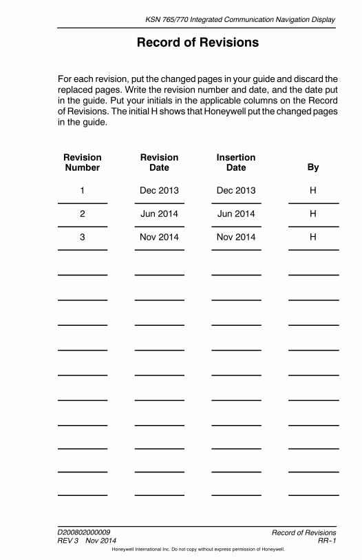
For each revision, put the changed pages in your guide and discard thereplaced pages. Write the revision number and date, and the date putin the guide. Put your initials in the applicable columns on the Recordof Revisions. The initial H shows that Honeywell put the changedpagesin the guide.
RevisionNumber
RevisionDate
InsertionDate By
1 Dec 2013 Dec 2013 H
2 Jun 2014 Jun 2014 H
3 Nov 2014 Nov 2014 H

KSN 765/770 Integrated Communication Navigation Display
D200802000009REV 2 Jun 2014
Record of RevisionsRR--2
Honeywell International Inc. Do not copy without express permission of Honeywell.
Blank Page
KSN 765/770 Integrated Communication Navigation Display
D200802000009REV 3 Nov 2014 LEP--1
List of Effective Pages
Honeywell International Inc. Do not copy without express permission of Honeywell.
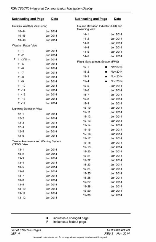
List of Effective Pages
Subheading and Page Date Subheading and Page Date
Title
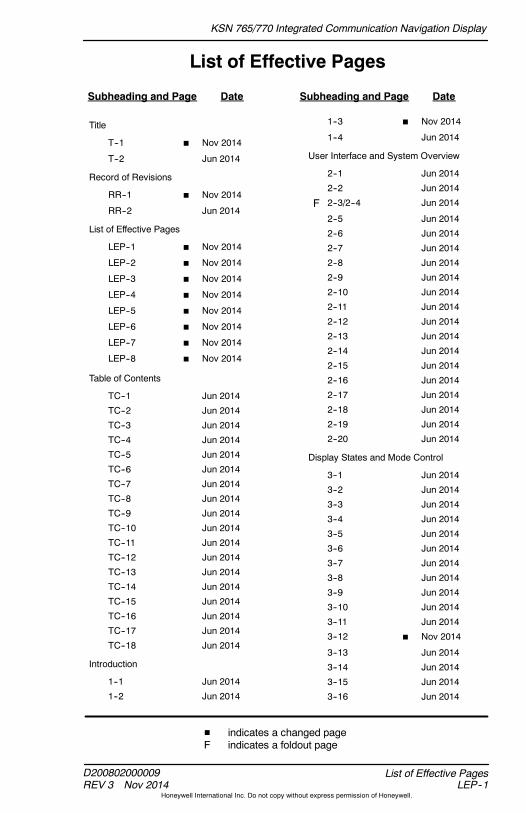
T--1 H Nov 2014
T--2 Jun 2014
Record of Revisions
RR--1 H Nov 2014
RR--2 Jun 2014
List of Effective Pages
LEP--1 H Nov 2014
LEP--2 H Nov 2014
LEP--3 H Nov 2014
LEP--4 H Nov 2014
LEP--5 H Nov 2014
LEP--6 H Nov 2014
LEP--7 H Nov 2014
LEP--8 H Nov 2014
Table of Contents
TC--1 Jun 2014
TC--2 Jun 2014
TC--3 Jun 2014
TC--4 Jun 2014
TC--5 Jun 2014
TC--6 Jun 2014
TC--7 Jun 2014
TC--8 Jun 2014
TC--9 Jun 2014
TC--10 Jun 2014
TC--11 Jun 2014
TC--12 Jun 2014
TC--13 Jun 2014
TC--14 Jun 2014
TC--15 Jun 2014
TC--16 Jun 2014
TC--17 Jun 2014
TC--18 Jun 2014
Introduction
1--1 Jun 2014
1--2 Jun 2014
1--3 H Nov 2014
1--4 Jun 2014
User Interface and System Overview
2--1 Jun 2014
2--2 Jun 2014
F 2--3/2--4 Jun 2014
2--5 Jun 2014
2--6 Jun 2014
2--7 Jun 2014
2--8 Jun 2014
2--9 Jun 2014
2--10 Jun 2014
2--11 Jun 2014
2--12 Jun 2014
2--13 Jun 2014
2--14 Jun 2014
2--15 Jun 2014
2--16 Jun 2014
2--17 Jun 2014
2--18 Jun 2014
2--19 Jun 2014
2--20 Jun 2014
Display States and Mode Control
3--1 Jun 2014
3--2 Jun 2014
3--3 Jun 2014
3--4 Jun 2014
3--5 Jun 2014
3--6 Jun 2014
3--7 Jun 2014
3--8 Jun 2014
3--9 Jun 2014
3--10 Jun 2014
3--11 Jun 2014
3--12 H Nov 2014
3--13 Jun 2014
3--14 Jun 2014
3--15 Jun 2014
3--16 Jun 2014
H indicates a changed pageF indicates a foldout page
KSN 765/770 Integrated Communication Navigation Display
D200802000009REV 3 Nov 2014
List of Effective PagesLEP--2
Honeywell International Inc. Do not copy without express permission of Honeywell.
Subheading and Page Date Subheading and Page Date
Menu
4--1 Jun 2014
4--2 Jun 2014
4--3 Jun 2014
4--4 Jun 2014
4--5 Jun 2014
4--6 Jun 2014
4--7 Jun 2014
4--8 Jun 2014
4--9 Jun 2014
4--10 Jun 2014
KSN 770 Radio
5--1 Jun 2014
5--2 Jun 2014
5--3 Jun 2014
5--4 Jun 2014
5--5 Jun 2014
5--6 Jun 2014
5--7 Jun 2014
5--8 Jun 2014
5--9 Jun 2014
5--10 Jun 2014
5--11 Jun 2014
5--12 Jun 2014
5--13 Jun 2014
5--14 Jun 2014
5--15 Jun 2014
5--16 Jun 2014
Navigation Map View
6--1 Jun 2014
6--2 Jun 2014
6--3 Jun 2014
6--4 Jun 2014
6--5 Jun 2014
6--6 Jun 2014
6--7 Jun 2014
6--8 Jun 2014
6--9 Jun 2014
6--10 Jun 2014
6--11 Jun 2014
6--12 Jun 2014
6--13 Jun 2014
6--14 Jun 2014
6--15 Jun 2014
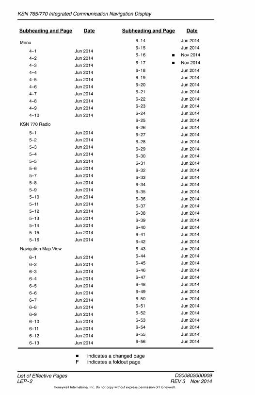
6--16 H Nov 2014
6--17 H Nov 2014
6--18 Jun 2014
6--19 Jun 2014
6--20 Jun 2014
6--21 Jun 2014
6--22 Jun 2014
6--23 Jun 2014
6--24 Jun 2014
6--25 Jun 2014
6--26 Jun 2014
6--27 Jun 2014
6--28 Jun 2014
6--29 Jun 2014
6--30 Jun 2014
6--31 Jun 2014
6--32 Jun 2014
6--33 Jun 2014
6--34 Jun 2014
6--35 Jun 2014
6--36 Jun 2014
6--37 Jun 2014
6--38 Jun 2014
6--39 Jun 2014
6--40 Jun 2014
6--41 Jun 2014
6--42 Jun 2014
6--43 Jun 2014
6--44 Jun 2014
6--45 Jun 2014
6--46 Jun 2014
6--47 Jun 2014
6--48 Jun 2014
6--49 Jun 2014
6--50 Jun 2014
6--51 Jun 2014
6--52 Jun 2014
6--53 Jun 2014
6--54 Jun 2014
6--55 Jun 2014
6--56 Jun 2014
H indicates a changed pageF indicates a foldout page

KSN 765/770 Integrated Communication Navigation Display
D200802000009REV 3 Nov 2014 LEP--3
List of Effective Pages
Honeywell International Inc. Do not copy without express permission of Honeywell.
Subheading and Page Date Subheading and Page Date
Charts View
7--1 Jun 2014
7--2 Jun 2014
7--3 Jun 2014
7--4 Jun 2014
7--5 Jun 2014
7--6 Jun 2014
7--7 Jun 2014
7--8 Jun 2014
7--9 Jun 2014
7--10 Jun 2014
7--11 Jun 2014
7--12 Jun 2014
7--13 Jun 2014
7--14 Jun 2014
7--15 Jun 2014
7--16 Jun 2014
7--17 Jun 2014
7--18 Jun 2014
Terrain View
8--1 Jun 2014
8--2 Jun 2014
8--3 Jun 2014
8--4 Jun 2014
8--5 Jun 2014
8--6 Jun 2014
8--7 Jun 2014
8--8 Jun 2014
8--9 Jun 2014
8--10 Jun 2014
Traffic View
9--1 Jun 2014
9--2 Jun 2014
9--3 Jun 2014
9--4 Jun 2014
9--5 Jun 2014
9--6 Jun 2014
9--7 Jun 2014
9--8 Jun 2014
Datalink Weather View
10--1 Jun 2014
10--2 Jun 2014
10--3 Jun 2014
10--4 Jun 2014
10--5 Jun 2014
10--6 Jun 2014
10--7 Jun 2014
10--8 Jun 2014
10--9 Jun 2014
10--10 Jun 2014
10--11 Jun 2014
10--12 Jun 2014
10--13 Jun 2014
10--14 Jun 2014
10--15 Jun 2014
10--16 Jun 2014
10--17 Jun 2014
10--18 Jun 2014
10--19 Jun 2014
10--20 Jun 2014
10--21 Jun 2014
10--22 Jun 2014
10--23 Jun 2014
10--24 Jun 2014
10--25 Jun 2014
10--26 Jun 2014
10--27 Jun 2014
10--28 Jun 2014
10--29 Jun 2014
10--30 Jun 2014
10--31 Jun 2014
10--32 Jun 2014
10--33 Jun 2014
10--34 Jun 2014
10--35 Jun 2014
10--36 Jun 2014
10--37 Jun 2014
10--38 Jun 2014
10--39 Jun 2014
10--40 Jun 2014
10--41 Jun 2014
10--42 Jun 2014
10--43 Jun 2014
H indicates a changed pageF indicates a foldout page
KSN 765/770 Integrated Communication Navigation Display
D200802000009REV 3 Nov 2014
List of Effective PagesLEP--4
Honeywell International Inc. Do not copy without express permission of Honeywell.
Subheading and Page Date Subheading and Page Date
Datalink Weather View (cont)
10--44 Jun 2014
10--45 Jun 2014
10--46 Jun 2014
Weather Radar View
11--1 Jun 2014
11--2 Jun 2014
F 11--3/11--4 Jun 2014
11--5 Jun 2014
11--6 Jun 2014
11--7 Jun 2014
11--8 Jun 2014
11--9 Jun 2014
11--10 Jun 2014
11--11 Jun 2014
11--12 Jun 2014
11--13 Jun 2014
11--14 Jun 2014
Lightning Detection View
12--1 Jun 2014
12--2 Jun 2014
12--3 Jun 2014
12--4 Jun 2014
12--5 Jun 2014
12--6 Jun 2014
Terrain Awareness and Warning System(TAWS) View
13--1 Jun 2014
13--2 Jun 2014
13--3 Jun 2014
13--4 Jun 2014
13--5 Jun 2014
13--6 Jun 2014
13--7 Jun 2014
13--8 Jun 2014
13--9 Jun 2014
13--10 Jun 2014
13--11 Jun 2014
13--12 Jun 2014
Course Deviation Indicator (CDI) andSwitching View
14--1 Jun 2014
14--2 Jun 2014
14--3 Jun 2014
14--4 Jun 2014
14--5 Jun 2014
14--6 Jun 2014
Flight Management System (FMS)
15--1 H Nov 2014
15--2 H Nov 2014
15--3 H Nov 2014
15--4 H Nov 2014
15--5 Jun 2014
15--6 Jun 2014
15--7 Jun 2014
15--8 Jun 2014
15--9 Jun 2014
15--10 Jun 2014
15--11 Jun 2014
15--12 Jun 2014
15--13 Jun 2014
15--14 Jun 2014
15--15 Jun 2014
15--16 Jun 2014
15--17 Jun 2014
15--18 Jun 2014
15--19 Jun 2014
15--20 Jun 2014
15--21 Jun 2014
15--22 Jun 2014
15--23 Jun 2014
15--24 Jun 2014
15--25 Jun 2014
15--26 Jun 2014
15--27 Jun 2014
15--28 Jun 2014
15--29 Jun 2014
15--30 Jun 2014
H indicates a changed pageF indicates a foldout page
KSN 765/770 Integrated Communication Navigation Display
D200802000009REV 3 Nov 2014 LEP--5
List of Effective Pages
Honeywell International Inc. Do not copy without express permission of Honeywell.
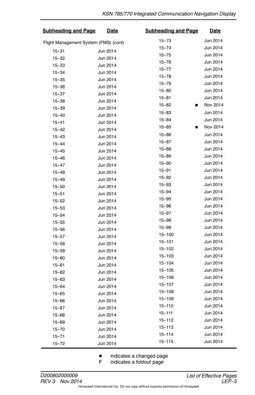
Subheading and Page Date Subheading and Page Date
Flight Management System (FMS) (cont)
15--31 Jun 2014
15--32 Jun 2014
15--33 Jun 2014
15--34 Jun 2014
15--35 Jun 2014
15--36 Jun 2014
15--37 Jun 2014
15--38 Jun 2014
15--39 Jun 2014
15--40 Jun 2014
15--41 Jun 2014
15--42 Jun 2014
15--43 Jun 2014
15--44 Jun 2014
15--45 Jun 2014
15--46 Jun 2014
15--47 Jun 2014
15--48 Jun 2014
15--49 Jun 2014
15--50 Jun 2014
15--51 Jun 2014
15--52 Jun 2014
15--53 Jun 2014
15--54 Jun 2014
15--55 Jun 2014
15--56 Jun 2014
15--57 Jun 2014
15--58 Jun 2014
15--59 Jun 2014
15--60 Jun 2014
15--61 Jun 2014
15--62 Jun 2014
15--63 Jun 2014
15--64 Jun 2014
15--65 Jun 2014
15--66 Jun 2014
15--67 Jun 2014
15--68 Jun 2014
15--69 Jun 2014
15--70 Jun 2014
15--71 Jun 2014
15--72 Jun 2014
15--73 Jun 2014
15--74 Jun 2014
15--75 Jun 2014
15--76 Jun 2014
15--77 Jun 2014
15--78 Jun 2014
15--79 Jun 2014
15--80 Jun 2014
15--81 Jun 2014
15--82 H Nov 2014
15--83 Jun 2014
15--84 Jun 2014
15--85 H Nov 2014
15--86 Jun 2014
15--87 Jun 2014
15--88 Jun 2014
15--89 Jun 2014
15--90 Jun 2014
15--91 Jun 2014
15--92 Jun 2014
15--93 Jun 2014
15--94 Jun 2014
15--95 Jun 2014
15--96 Jun 2014
15--97 Jun 2014
15--98 Jun 2014
15--99 Jun 2014
15--100 Jun 2014
15--101 Jun 2014
15--102 Jun 2014
15--103 Jun 2014
15--104 Jun 2014
15--105 Jun 2014
15--106 Jun 2014
15--107 Jun 2014
15--108 Jun 2014
15--109 Jun 2014
15--110 Jun 2014
15--111 Jun 2014
15--112 Jun 2014
15--113 Jun 2014
15--114 Jun 2014
15--115 Jun 2014
H indicates a changed pageF indicates a foldout page
KSN 765/770 Integrated Communication Navigation Display
D200802000009REV 3 Nov 2014
List of Effective PagesLEP--6
Honeywell International Inc. Do not copy without express permission of Honeywell.
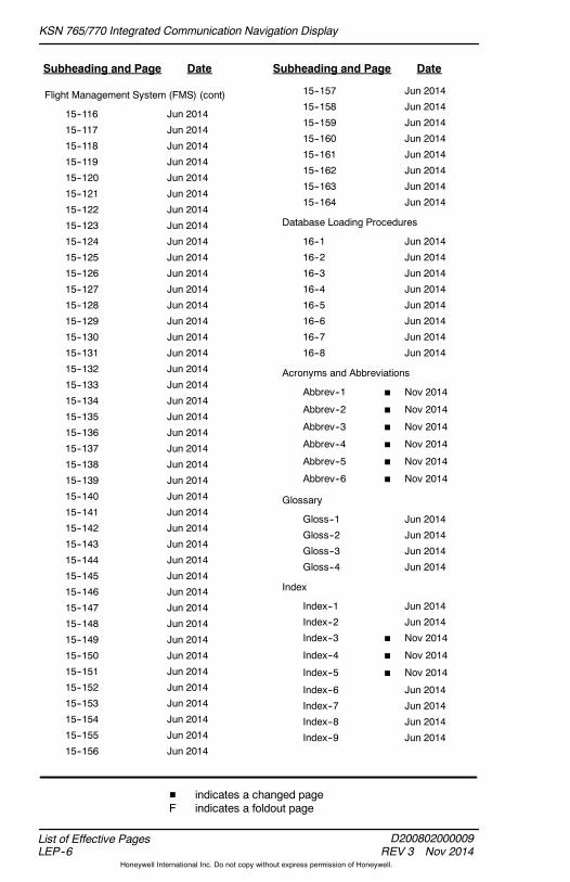
Subheading and Page Date Subheading and Page Date
Flight Management System (FMS) (cont)
15--116 Jun 2014
15--117 Jun 2014
15--118 Jun 2014
15--119 Jun 2014
15--120 Jun 2014
15--121 Jun 2014
15--122 Jun 2014
15--123 Jun 2014
15--124 Jun 2014
15--125 Jun 2014
15--126 Jun 2014
15--127 Jun 2014
15--128 Jun 2014
15--129 Jun 2014
15--130 Jun 2014
15--131 Jun 2014
15--132 Jun 2014
15--133 Jun 2014
15--134 Jun 2014
15--135 Jun 2014
15--136 Jun 2014
15--137 Jun 2014
15--138 Jun 2014
15--139 Jun 2014
15--140 Jun 2014
15--141 Jun 2014
15--142 Jun 2014
15--143 Jun 2014
15--144 Jun 2014
15--145 Jun 2014
15--146 Jun 2014
15--147 Jun 2014
15--148 Jun 2014
15--149 Jun 2014
15--150 Jun 2014
15--151 Jun 2014
15--152 Jun 2014
15--153 Jun 2014
15--154 Jun 2014
15--155 Jun 2014
15--156 Jun 2014
15--157 Jun 2014
15--158 Jun 2014
15--159 Jun 2014
15--160 Jun 2014
15--161 Jun 2014
15--162 Jun 2014
15--163 Jun 2014
15--164 Jun 2014
Database Loading Procedures
16--1 Jun 2014
16--2 Jun 2014
16--3 Jun 2014
16--4 Jun 2014
16--5 Jun 2014
16--6 Jun 2014
16--7 Jun 2014
16--8 Jun 2014
Acronyms and Abbreviations
Abbrev--1 H Nov 2014
Abbrev--2 H Nov 2014
Abbrev--3 H Nov 2014
Abbrev--4 H Nov 2014
Abbrev--5 H Nov 2014
Abbrev--6 H Nov 2014
Glossary
Gloss--1 Jun 2014
Gloss--2 Jun 2014
Gloss--3 Jun 2014
Gloss--4 Jun 2014
Index
Index--1 Jun 2014
Index--2 Jun 2014
Index--3 H Nov 2014
Index--4 H Nov 2014
Index--5 H Nov 2014
Index--6 Jun 2014
Index--7 Jun 2014
Index--8 Jun 2014
Index--9 Jun 2014
H indicates a changed pageF indicates a foldout page

KSN 765/770 Integrated Communication Navigation Display
D200802000009REV 3 Nov 2014 LEP--7
List of Effective Pages
Honeywell International Inc. Do not copy without express permission of Honeywell.
Subheading and Page Date Subheading and Page Date
Index (cont)
Index--10 Jun 2014
Index--11 Jun 2014
Index--12 Jun 2014
H indicates a changed pageF indicates a foldout page

KSN 765/770 Integrated Communication Navigation Display
D200802000009REV 2 Jun 2014
List of Effective PagesLEP--8
Honeywell International Inc. Do not copy without express permission of Honeywell.
Blank Page

KSN 765/770 Integrated Communication Navigation Display
D200802000009REV 2 Jun 2014 TC--1
Table of Contents
Honeywell International Inc. Do not copy without express permission of Honeywell.
Table of Contents
Section Page
1. INTRODUCTION 1-1. . . . . . . . . . . . . . . . . . . . . . . . . . . . .
Structure of This Guide 1-1. . . . . . . . . . . . . . . . . . . . . . .Customer Support 1-3. . . . . . . . . . . . . . . . . . . . . . . . . . . .BendixKing Technical Publications 1-3. . . . . . . . . . . . . .
2. USER INTERFACE AND SYSTEM OVERVIEW 2-1.
Introduction 2-1. . . . . . . . . . . . . . . . . . . . . . . . . . . . . . . . .Terminology and Descriptions 2-1. . . . . . . . . . . . . . . . . .User Controls 2-7. . . . . . . . . . . . . . . . . . . . . . . . . . . . . . . .
Volume Knob (KSN 770 Only) 2-8. . . . . . . . . . . . . . .Radio Control Knob 2-8. . . . . . . . . . . . . . . . . . . . . . . .Joystick Knob 2-8. . . . . . . . . . . . . . . . . . . . . . . . . . . . .Dedicated Bezel Keys 2-9. . . . . . . . . . . . . . . . . . . . . .Bezel Softkeys 2-10. . . . . . . . . . . . . . . . . . . . . . . . . . . .Interactive Touchscreen Interface 2-10. . . . . . . . . . . .Keypads 2-11. . . . . . . . . . . . . . . . . . . . . . . . . . . . . . . . .Scroll Bars 2-12. . . . . . . . . . . . . . . . . . . . . . . . . . . . . . .
Color Convention 2-12. . . . . . . . . . . . . . . . . . . . . . . . . . . . .Pop--Up Alerts 2-14. . . . . . . . . . . . . . . . . . . . . . . . . . . . . . .Text Data Bar 2-16. . . . . . . . . . . . . . . . . . . . . . . . . . . . . . . .
Invalid States 2-18. . . . . . . . . . . . . . . . . . . . . . . . . . . . .Aircraft Symbol (Ownship) 2-18. . . . . . . . . . . . . . . . . . . . .True North Orientation Indicator Symbol 2-18. . . . . . . . .Acknowledgement Confirmation Page 2-19. . . . . . . . . . .
3. DISPLAY STATES AND MODE CONTROL 3-1. . . . .
Introduction 3-1. . . . . . . . . . . . . . . . . . . . . . . . . . . . . . . . .Page Layout 3-1. . . . . . . . . . . . . . . . . . . . . . . . . . . . . . . . .
MFD Layouts 3-1. . . . . . . . . . . . . . . . . . . . . . . . . . . . .FMS Layouts 3-5. . . . . . . . . . . . . . . . . . . . . . . . . . . . .
View Control Mode 3-6. . . . . . . . . . . . . . . . . . . . . . . . . . .Focus Selection 3-6. . . . . . . . . . . . . . . . . . . . . . . . . . .View Selection 3-7. . . . . . . . . . . . . . . . . . . . . . . . . . . .
Left and Right Bezel Softkeys 3-9. . . . . . . . . . . . . . . . . .Bezel Softkey Labels 3-9. . . . . . . . . . . . . . . . . . . . . .Active/Inactive Bezel Softkey Labels 3-10. . . . . . . . .Touchscreen Buttons 3-11. . . . . . . . . . . . . . . . . . . . . .
Panning 3-11. . . . . . . . . . . . . . . . . . . . . . . . . . . . . . . . . . . . .Panning View Control Mode 3-12. . . . . . . . . . . . . . . .
Failure/Status Annunciations 3-13. . . . . . . . . . . . . . . . . . .GPS Failure Annunciation 3-14. . . . . . . . . . . . . . . . . .

KSN 765/770 Integrated Communication Navigation Display
D200802000009REV 2 Jun 2014
Table of ContentsTC--2
Honeywell International Inc. Do not copy without express permission of Honeywell.
Table of Contents (cont)
Section Page
3. DISPLAY STATES AND MODE CONTROL (CONT)
Failure/Status Annunciations (cont)GPS Acquisition Status Annunciation 3-14. . . . . . . .GPS Loss of Integrity Status Annunciation 3-14. . . .FMS Failure Annunciation 3-14. . . . . . . . . . . . . . . . . .Fan Failure Annunciation 3-14. . . . . . . . . . . . . . . . . . .Over Temp Status Annunciation 3-15. . . . . . . . . . . . .Altitude Failure Annunciation 3-15. . . . . . . . . . . . . . . .Heading Failure Annunciation 3-15. . . . . . . . . . . . . . .True Air Speed (TAS) Failure Annunciation 3-15. . .Receiver Autonomous Integrity Monitoring(RAIM) Failure Annunciation 3-15. . . . . . . . . . . . . . .
Navigation Database (NAV DB) FailureAnnunciation 3-16. . . . . . . . . . . . . . . . . . . . . . . . . . . .
4. MENU 4-1. . . . . . . . . . . . . . . . . . . . . . . . . . . . . . . . . . . . . .
Introduction 4-1. . . . . . . . . . . . . . . . . . . . . . . . . . . . . . . . .Menu Control Overview 4-1. . . . . . . . . . . . . . . . . . . . . . .
General Menu Operation 4-2. . . . . . . . . . . . . . . . . . .Edit Mode Operation 4-4. . . . . . . . . . . . . . . . . . . . . . .Menu Controls 4-4. . . . . . . . . . . . . . . . . . . . . . . . . . . .
5. KSN 770 RADIO 5-1. . . . . . . . . . . . . . . . . . . . . . . . . . . . .
Introduction 5-1. . . . . . . . . . . . . . . . . . . . . . . . . . . . . . . . .Volume Control 5-1. . . . . . . . . . . . . . . . . . . . . . . . . . . . . .COM Squelch and NAV Identifier Control 5-3. . . . . . . .Radio Tuning and Display 5-5. . . . . . . . . . . . . . . . . . . . .
Switching Radio Sources 5-6. . . . . . . . . . . . . . . . . . .NAV Radio Autotune 5-6. . . . . . . . . . . . . . . . . . . . . . .Touchscreen Tuning 5-7. . . . . . . . . . . . . . . . . . . . . . .Stored Frequency List 5-8. . . . . . . . . . . . . . . . . . . . . .Nearest Airport Frequency Control 5-11. . . . . . . . . . .Nearest ARTCC Frequency Control 5-13. . . . . . . . . .Nearest FSS Frequency Control 5-14. . . . . . . . . . . . .Nearest NAV Frequency Control 5-15. . . . . . . . . . . . .Abnormal Radio Annunciations 5-16. . . . . . . . . . . . . .
6. NAVIGATION MAP VIEW 6-1. . . . . . . . . . . . . . . . . . . . .
Introduction 6-1. . . . . . . . . . . . . . . . . . . . . . . . . . . . . . . . .Navigation Map Overview 6-1. . . . . . . . . . . . . . . . . . . . .
Navigation Map Orientation Annunciators 6-4. . . . .Heading and Track Display 6-8. . . . . . . . . . . . . . . . .
KSN 765/770 Integrated Communication Navigation Display
D200802000009REV 2 Jun 2014 TC--3
Table of Contents
Honeywell International Inc. Do not copy without express permission of Honeywell.
Table of Contents (cont)
Section Page
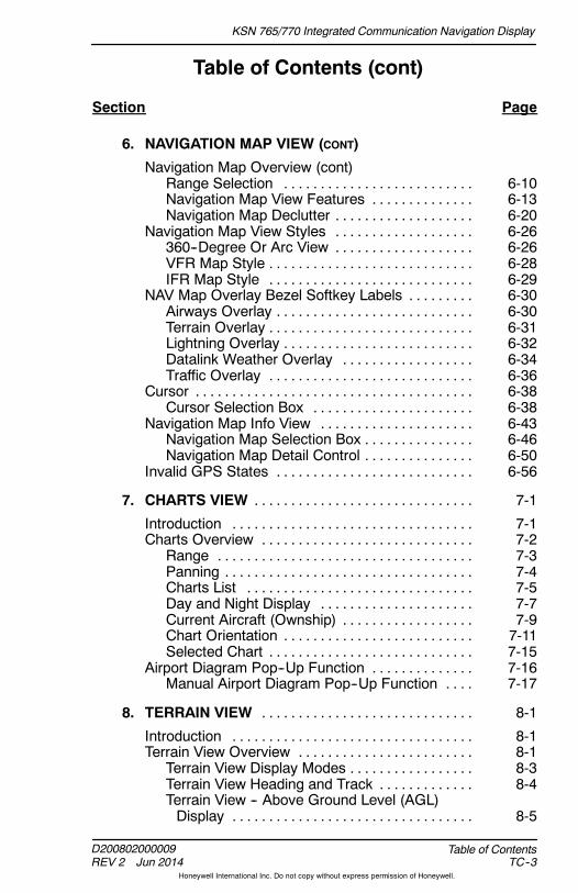
6. NAVIGATION MAP VIEW (CONT)
Navigation Map Overview (cont)Range Selection 6-10. . . . . . . . . . . . . . . . . . . . . . . . . .Navigation Map View Features 6-13. . . . . . . . . . . . . .Navigation Map Declutter 6-20. . . . . . . . . . . . . . . . . . .
Navigation Map View Styles 6-26. . . . . . . . . . . . . . . . . . .360--Degree Or Arc View 6-26. . . . . . . . . . . . . . . . . . .VFR Map Style 6-28. . . . . . . . . . . . . . . . . . . . . . . . . . . .IFR Map Style 6-29. . . . . . . . . . . . . . . . . . . . . . . . . . . .
NAV Map Overlay Bezel Softkey Labels 6-30. . . . . . . . .Airways Overlay 6-30. . . . . . . . . . . . . . . . . . . . . . . . . . .Terrain Overlay 6-31. . . . . . . . . . . . . . . . . . . . . . . . . . . .Lightning Overlay 6-32. . . . . . . . . . . . . . . . . . . . . . . . . .Datalink Weather Overlay 6-34. . . . . . . . . . . . . . . . . .Traffic Overlay 6-36. . . . . . . . . . . . . . . . . . . . . . . . . . . .
Cursor 6-38. . . . . . . . . . . . . . . . . . . . . . . . . . . . . . . . . . . . . .Cursor Selection Box 6-38. . . . . . . . . . . . . . . . . . . . . .
Navigation Map Info View 6-43. . . . . . . . . . . . . . . . . . . . .Navigation Map Selection Box 6-46. . . . . . . . . . . . . . .Navigation Map Detail Control 6-50. . . . . . . . . . . . . . .
Invalid GPS States 6-56. . . . . . . . . . . . . . . . . . . . . . . . . . .
7. CHARTS VIEW 7-1. . . . . . . . . . . . . . . . . . . . . . . . . . . . . .
Introduction 7-1. . . . . . . . . . . . . . . . . . . . . . . . . . . . . . . . .Charts Overview 7-2. . . . . . . . . . . . . . . . . . . . . . . . . . . . .
Range 7-3. . . . . . . . . . . . . . . . . . . . . . . . . . . . . . . . . . .Panning 7-4. . . . . . . . . . . . . . . . . . . . . . . . . . . . . . . . . .Charts List 7-5. . . . . . . . . . . . . . . . . . . . . . . . . . . . . . .Day and Night Display 7-7. . . . . . . . . . . . . . . . . . . . .Current Aircraft (Ownship) 7-9. . . . . . . . . . . . . . . . . .Chart Orientation 7-11. . . . . . . . . . . . . . . . . . . . . . . . . .Selected Chart 7-15. . . . . . . . . . . . . . . . . . . . . . . . . . . .
Airport Diagram Pop--Up Function 7-16. . . . . . . . . . . . . .Manual Airport Diagram Pop--Up Function 7-17. . . .
8. TERRAIN VIEW 8-1. . . . . . . . . . . . . . . . . . . . . . . . . . . . .
Introduction 8-1. . . . . . . . . . . . . . . . . . . . . . . . . . . . . . . . .Terrain View Overview 8-1. . . . . . . . . . . . . . . . . . . . . . . .
Terrain View Display Modes 8-3. . . . . . . . . . . . . . . . .Terrain View Heading and Track 8-4. . . . . . . . . . . . .Terrain View -- Above Ground Level (AGL)Display 8-5. . . . . . . . . . . . . . . . . . . . . . . . . . . . . . . . .

KSN 765/770 Integrated Communication Navigation Display
D200802000009REV 2 Jun 2014
Table of ContentsTC--4
Honeywell International Inc. Do not copy without express permission of Honeywell.
Table of Contents (cont)
Section Page
8. TERRAIN VIEW (CONT)
Terrain View Overview (cont)Terrain Legend 8-6. . . . . . . . . . . . . . . . . . . . . . . . . . . .
Obstruction and Terrain Coloring 8-6. . . . . . . . . . . . . . .Obstruction Coloring 8-7. . . . . . . . . . . . . . . . . . . . . . .Terrain Coloring 8-8. . . . . . . . . . . . . . . . . . . . . . . . . . .Terrain View Failures 8-10. . . . . . . . . . . . . . . . . . . . . . .
9. TRAFFIC VIEW 9-1. . . . . . . . . . . . . . . . . . . . . . . . . . . . . .
Introduction 9-1. . . . . . . . . . . . . . . . . . . . . . . . . . . . . . . . .Traffic Display 9-2. . . . . . . . . . . . . . . . . . . . . . . . . . . . . . .
Traffic Features 9-4. . . . . . . . . . . . . . . . . . . . . . . . . . .Traffic Altitude Filter 9-5. . . . . . . . . . . . . . . . . . . . . . .No Bearing Advisories 9-5. . . . . . . . . . . . . . . . . . . . .Off Scale and Symbol Overlap 9-5. . . . . . . . . . . . . .Traffic Pop--Up Mode 9-6. . . . . . . . . . . . . . . . . . . . . .Traffic Status Display 9-7. . . . . . . . . . . . . . . . . . . . . .
10. DATALINK WEATHER VIEW 10-1. . . . . . . . . . . . . . . . . .
Introduction 10-1. . . . . . . . . . . . . . . . . . . . . . . . . . . . . . . . .Weather View Overview 10-2. . . . . . . . . . . . . . . . . . . . . . .
Datalink Weather View Orientation 10-4. . . . . . . . . . .Datalink Weather View Range Selection 10-5. . . . . .XM Product Ages 10-5. . . . . . . . . . . . . . . . . . . . . . . . .
Datalink Weather Pages 10-8. . . . . . . . . . . . . . . . . . . . . .Convective Page 10-10. . . . . . . . . . . . . . . . . . . . . . . . . .METARS Page 10-18. . . . . . . . . . . . . . . . . . . . . . . . . . . .Echo Tops Page 10-24. . . . . . . . . . . . . . . . . . . . . . . . . . .Cloud Tops Page 10-26. . . . . . . . . . . . . . . . . . . . . . . . . .AIRMET/SIGMET Page 10-28. . . . . . . . . . . . . . . . . . . .Temporary Flight Restriction (TFR) Page 10-32. . . . .Winds Aloft Page 10-35. . . . . . . . . . . . . . . . . . . . . . . . . .XM Status Page 10-37. . . . . . . . . . . . . . . . . . . . . . . . . . .
11. WEATHER RADAR VIEW 11-1. . . . . . . . . . . . . . . . . . . .
Introduction 11-1. . . . . . . . . . . . . . . . . . . . . . . . . . . . . . . . .Weather Radar View Overview 11-2. . . . . . . . . . . . . . . . .
Operational Mode Control 11-5. . . . . . . . . . . . . . . . . .Weather Radar Range Selection 11-11. . . . . . . . . . . .Weather Radar Alert Mode 11-12. . . . . . . . . . . . . . . . .Weather Radar Faults 11-13. . . . . . . . . . . . . . . . . . . . . .
KSN 765/770 Integrated Communication Navigation Display
D200802000009REV 2 Jun 2014 TC--5
Table of Contents
Honeywell International Inc. Do not copy without express permission of Honeywell.
Table of Contents (cont)
Section Page
12. LIGHTNING DETECTION VIEW 12-1. . . . . . . . . . . . . . .
Introduction 12-1. . . . . . . . . . . . . . . . . . . . . . . . . . . . . . . . .Strikes Overview 12-2. . . . . . . . . . . . . . . . . . . . . . . . . . . . .
Strikes View Modes 12-2. . . . . . . . . . . . . . . . . . . . . . . .Strikes Display Modes 12-3. . . . . . . . . . . . . . . . . . . . .Strikes Sensor Status 12-4. . . . . . . . . . . . . . . . . . . . . .Error Annunciators 12-5. . . . . . . . . . . . . . . . . . . . . . . .
13. TERRAIN AWARENESS AND WARNING SYSTEM(TAWS) VIEW 13-1. . . . . . . . . . . . . . . . . . . . . . . . . . . . . .
Introduction 13-1. . . . . . . . . . . . . . . . . . . . . . . . . . . . . . . . .TAWS Overview 13-1. . . . . . . . . . . . . . . . . . . . . . . . . . . . .
TAWS Symbols 13-3. . . . . . . . . . . . . . . . . . . . . . . . . . .Display Orientation 13-4. . . . . . . . . . . . . . . . . . . . . . . .Failure Annunciations 13-5. . . . . . . . . . . . . . . . . . . . . .TAWS Terrain and Obstacle Data 13-7. . . . . . . . . . . .TAWS Range Selection 13-11. . . . . . . . . . . . . . . . . . . .TAWS Pop--Up Mode 13-12. . . . . . . . . . . . . . . . . . . . . .
14. COURSE DEVIATION INDICATOR (CDI) ANDSWITCHING VIEW 14-1. . . . . . . . . . . . . . . . . . . . . . . . .
Introduction 14-1. . . . . . . . . . . . . . . . . . . . . . . . . . . . . . . . .CDI Scaling 14-4. . . . . . . . . . . . . . . . . . . . . . . . . . . . . . .CDI Off Scale 14-5. . . . . . . . . . . . . . . . . . . . . . . . . . . . .GPS NAV Switching (KSN 770 Only) 14-6. . . . . . . . .
15. FLIGHT MANAGEMENT SYSTEM (FMS) 15-1. . . . . . .
Introduction 15-1. . . . . . . . . . . . . . . . . . . . . . . . . . . . . . . . .Legacy Autopilot System Interaction 15-1. . . . . . . . .
FMS Database Description 15-1. . . . . . . . . . . . . . . . . . . .Real Time Clock 15-4. . . . . . . . . . . . . . . . . . . . . . . . . . .Position Initialization 15-5. . . . . . . . . . . . . . . . . . . . . . .
Waypoint Sequencing and Suspending aFlight Plan 15-6. . . . . . . . . . . . . . . . . . . . . . . . . . . . . . . . .
FMS Function Display 15-7. . . . . . . . . . . . . . . . . . . . . . . .FMS Home Window 15-9. . . . . . . . . . . . . . . . . . . . . . .Waypoint List Window 15-10. . . . . . . . . . . . . . . . . . . . . .
Example Flight Plan 15-12. . . . . . . . . . . . . . . . . . . . . . . . . .Flight Plan Route Entry 15-12. . . . . . . . . . . . . . . . . . . . .Departure Procedures 15-18. . . . . . . . . . . . . . . . . . . . .En Route Waypoints 15-24. . . . . . . . . . . . . . . . . . . . . . .Arrival Procedures 15-29. . . . . . . . . . . . . . . . . . . . . . . . .
KSN 765/770 Integrated Communication Navigation Display
D200802000009REV 2 Jun 2014
Table of ContentsTC--6
Honeywell International Inc. Do not copy without express permission of Honeywell.
Table of Contents (cont)
Section Page
15. FLIGHT MANAGEMENT SYSTEM (FMS) (CONT)
Example Flight Plan (cont)Approach Procedures 15-33. . . . . . . . . . . . . . . . . . . . . .Missed Approach Procedures 15-45. . . . . . . . . . . . . . .Procedure Turns 15-48. . . . . . . . . . . . . . . . . . . . . . . . . .Graphical Edit 15-50. . . . . . . . . . . . . . . . . . . . . . . . . . . . .Changing or Deleting an Entered Procedure 15-56. .Reviewing FMS Flight Plan Waypoints 15-59. . . . . . .Changing the Destination 15-60. . . . . . . . . . . . . . . . . . .Changing Flight Plan Waypoints 15-62. . . . . . . . . . . . .Deleting Flight Plan Waypoints 15-65. . . . . . . . . . . . . .Clearing Flight Plans 15-67. . . . . . . . . . . . . . . . . . . . . . .Route Discontinuity 15-67. . . . . . . . . . . . . . . . . . . . . . . .Direct--To and Nearest Function 15-70. . . . . . . . . . . . .Changing the FROM Waypoint 15-76. . . . . . . . . . . . . .Multiple Database Waypoints With SameIdentifier 15-77. . . . . . . . . . . . . . . . . . . . . . . . . . . . . . . .
Temporary Waypoint 15-78. . . . . . . . . . . . . . . . . . . . . . .Flight Plan Data 15-79. . . . . . . . . . . . . . . . . . . . . . . . . . . . . .Waypoint List Symbols 15-80. . . . . . . . . . . . . . . . . . . . . . . .
Altitude Constraints 15-80. . . . . . . . . . . . . . . . . . . . . . . .Pattern Icons 15-81. . . . . . . . . . . . . . . . . . . . . . . . . . . . .
Special Waypoint Identifiers 15-81. . . . . . . . . . . . . . . . . . .Special Leg Type Waypoints 15-82. . . . . . . . . . . . . . . .Altitude Sequence Legs 15-84. . . . . . . . . . . . . . . . . . . .Flight Segments 15-85. . . . . . . . . . . . . . . . . . . . . . . . . . .Notifications 15-86. . . . . . . . . . . . . . . . . . . . . . . . . . . . . .
FMS Home Window Bezel Softkey Labels 15-86. . . . . . .Omni Bearing Selector (OBS) 15-87. . . . . . . . . . . . . . .Global Positioning System/VOR Localizer(GPS/VLOC) 15-90. . . . . . . . . . . . . . . . . . . . . . . . . . . .
Procedures (PROC) 15-92. . . . . . . . . . . . . . . . . . . . . . .Holding 15-92. . . . . . . . . . . . . . . . . . . . . . . . . . . . . . . . . .Offsets 15-107. . . . . . . . . . . . . . . . . . . . . . . . . . . . . . . . . . .Search (SRCH) 15-111. . . . . . . . . . . . . . . . . . . . . . . . . . .Off--Aircraft Created Flight Plan(Future Option) 15-114. . . . . . . . . . . . . . . . . . . . . . . . . .
Creating a User Waypoint 15-116. . . . . . . . . . . . . . . . . .Storing Flight Plans 15-126. . . . . . . . . . . . . . . . . . . . . . . .Copying Flight Plans 15-139. . . . . . . . . . . . . . . . . . . . . . .
FMS Flight Plan Map Data 15-141. . . . . . . . . . . . . . . . . . . .

KSN 765/770 Integrated Communication Navigation Display
D200802000009REV 2 Jun 2014 TC--7
Table of Contents
Honeywell International Inc. Do not copy without express permission of Honeywell.
Table of Contents (cont)
Section Page
15. FLIGHT MANAGEMENT SYSTEM (FMS) (CONT)
FMS Phase of Flight 15-144. . . . . . . . . . . . . . . . . . . . . . . . . .FMS Messages 15-145. . . . . . . . . . . . . . . . . . . . . . . . . . . . . .Waypoint Detail Page (2/3) 15-151. . . . . . . . . . . . . . . . . . . .Utility Page 15-153. . . . . . . . . . . . . . . . . . . . . . . . . . . . . . . . . .
Trip Planner 15-154. . . . . . . . . . . . . . . . . . . . . . . . . . . . . .RAIM Prediction 15-156. . . . . . . . . . . . . . . . . . . . . . . . . . .Flight Timers 15-158. . . . . . . . . . . . . . . . . . . . . . . . . . . . . .Fuel Calculator 15-160. . . . . . . . . . . . . . . . . . . . . . . . . . . .Lock Screen 15-163. . . . . . . . . . . . . . . . . . . . . . . . . . . . . .
16. DATABASE LOADING PROCEDURES 16-1. . . . . . . . .
Introduction 16-1. . . . . . . . . . . . . . . . . . . . . . . . . . . . . . . . .Database Loading Overview 16-1. . . . . . . . . . . . . . . . . . .
Dataloading Errors 16-5. . . . . . . . . . . . . . . . . . . . . . . .
ACRONYMS AND ABBREVIATIONS Abbrev--1. . . . . . . . . . . . . . .
GLOSSARY Gloss--1. . . . . . . . . . . . . . . . . . . . . . . . . . . . . . . . . . . . .
INDEX Index--1. . . . . . . . . . . . . . . . . . . . . . . . . . . . . . . . . . . . . . . . . .

KSN 765/770 Integrated Communication Navigation Display
D200802000009REV 2 Jun 2014
Table of ContentsTC--8
Honeywell International Inc. Do not copy without express permission of Honeywell.
Table of Contents (cont)
List of Figures
Figure Page
2--1 MFD Function Layouts 2-3. . . . . . . . . . . . . . . . . . . . . . . .2--2 FMS Function Layouts 2-3. . . . . . . . . . . . . . . . . . . . . . . .2--3 FOCUS 2-6. . . . . . . . . . . . . . . . . . . . . . . . . . . . . . . . . . . . .2--4 KSN 770 User Controls 2-7. . . . . . . . . . . . . . . . . . . . . . .2--5 QWERTY Keypad 2-11. . . . . . . . . . . . . . . . . . . . . . . . . . . .2--6 Scroll Bars 2-12. . . . . . . . . . . . . . . . . . . . . . . . . . . . . . . . . .2--7 Pop--Up Alert 2-14. . . . . . . . . . . . . . . . . . . . . . . . . . . . . . . .2--8 Text Data Bar 2-16. . . . . . . . . . . . . . . . . . . . . . . . . . . . . . . .2--9 FMS Message 2-17. . . . . . . . . . . . . . . . . . . . . . . . . . . . . . .2--10 SUSPEND Annunciation 2-18. . . . . . . . . . . . . . . . . . . . . .2--11 Acknowledgement Confirmation Page 2-19. . . . . . . . . . .2--12 Database Expired and Not Yet Valid 2-20. . . . . . . . . . . .
3--1 Full Screen Layout 3-2. . . . . . . . . . . . . . . . . . . . . . . . . . .3--2 Split Screen Layout 3-3. . . . . . . . . . . . . . . . . . . . . . . . . . .3--3 Thumbnail Screen Layout 3-4. . . . . . . . . . . . . . . . . . . . .3--4 Window Selection 3-6. . . . . . . . . . . . . . . . . . . . . . . . . . . .3--5 Inactive and Active View Control State 3-7. . . . . . . . . .3--6 View Selection Menu 3-8. . . . . . . . . . . . . . . . . . . . . . . . .3--7 Bezel Softkeys and Bezel Softkey Labels 3-9. . . . . . . .3--8 Bezel Softkey Labels 3-10. . . . . . . . . . . . . . . . . . . . . . . . .3--9 Panning Activated Navigation Map Display 3-12. . . . . .
4--1 Menu Overview 4-1. . . . . . . . . . . . . . . . . . . . . . . . . . . . . .4--2 Editable Menu Item 4-3. . . . . . . . . . . . . . . . . . . . . . . . . . .4--3 Status Item 4-3. . . . . . . . . . . . . . . . . . . . . . . . . . . . . . . . . .4--4 Non--Editable Field 4-3. . . . . . . . . . . . . . . . . . . . . . . . . . .4--5 Edit Mode Active 4-4. . . . . . . . . . . . . . . . . . . . . . . . . . . . .4--6 True Selected for NAV Map Orientation 4-10. . . . . . . . .
5--1 KSN 770 Radio Overview 5-1. . . . . . . . . . . . . . . . . . . . .5--2 COM Radio Control Pop--Up Window 5-2. . . . . . . . . . .5--3 NAV Radio Control Pop--Up Window 5-2. . . . . . . . . . . .5--4 Squelch On and Off 5-3. . . . . . . . . . . . . . . . . . . . . . . . . .5--5 NAV Ident On and Off 5-3. . . . . . . . . . . . . . . . . . . . . . . . .5--6 COM/NAV Pop--Up Window States 5-4. . . . . . . . . . . . .5--7 Standby and Active Frequencies 5-5. . . . . . . . . . . . . . .5--8 Tuned Standby Frequency 5-5. . . . . . . . . . . . . . . . . . . . .5--9 Radio Frequency Tuning Pop--Up Window 5-7. . . . . . .5--10 Stored Frequencies 5-8. . . . . . . . . . . . . . . . . . . . . . . . . . .5--11 Edit Frequency 5-9. . . . . . . . . . . . . . . . . . . . . . . . . . . . . .
KSN 765/770 Integrated Communication Navigation Display
D200802000009REV 2 Jun 2014 TC--9
Table of Contents
Honeywell International Inc. Do not copy without express permission of Honeywell.
Table of Contents (cont)
List of Figures (cont)
Figure Page
5--12 Delete Stored Frequency 5-10. . . . . . . . . . . . . . . . . . . . . .5--13 Nearest Airport Frequencies 5-11. . . . . . . . . . . . . . . . . . .5--14 Selected Airport COM Frequencies 5-12. . . . . . . . . . . . .5--15 Nearest ARTCC Frequencies 5-13. . . . . . . . . . . . . . . . . .5--16 Nearest FSS Frequencies 5-14. . . . . . . . . . . . . . . . . . . . .5--17 Nearest VOR Frequencies 5-15. . . . . . . . . . . . . . . . . . . . .5--18 NAV/COM Radio Failure 5-16. . . . . . . . . . . . . . . . . . . . . .5--19 XMIT FAIL 5-16. . . . . . . . . . . . . . . . . . . . . . . . . . . . . . . . . .5--20 STUCK MIC 5-16. . . . . . . . . . . . . . . . . . . . . . . . . . . . . . . . .
6--1 Navigation Map View 6-1. . . . . . . . . . . . . . . . . . . . . . . . .6--2 PAN MODE Active 6-6. . . . . . . . . . . . . . . . . . . . . . . . . . .6--3 Direction of Flight -- Numerical Value 6-8. . . . . . . . . . . .6--4 Track Line 6-9. . . . . . . . . . . . . . . . . . . . . . . . . . . . . . . . . . .6--5 Range Selection 6-10. . . . . . . . . . . . . . . . . . . . . . . . . . . . .6--6 Auto--Range Active 6-11. . . . . . . . . . . . . . . . . . . . . . . . . . .6--7 Obstruction Symbols 6-19. . . . . . . . . . . . . . . . . . . . . . . . .6--8 Declutter Icons 6-24. . . . . . . . . . . . . . . . . . . . . . . . . . . . . . .6--9 ARC Mode 6-26. . . . . . . . . . . . . . . . . . . . . . . . . . . . . . . . . .6--10 360--Degree Mode 6-27. . . . . . . . . . . . . . . . . . . . . . . . . . .6--11 VFR Map 6-28. . . . . . . . . . . . . . . . . . . . . . . . . . . . . . . . . . .6--12 IFR Map 6-29. . . . . . . . . . . . . . . . . . . . . . . . . . . . . . . . . . . .6--13 LOW Airways 6-30. . . . . . . . . . . . . . . . . . . . . . . . . . . . . . . .6--14 Terrain Overlay 6-31. . . . . . . . . . . . . . . . . . . . . . . . . . . . . .6--15 Lightning Overlay 6-32. . . . . . . . . . . . . . . . . . . . . . . . . . . .6--16 Datalink Weather Overlay 6-34. . . . . . . . . . . . . . . . . . . . .6--17 Traffic Overlay 6-36. . . . . . . . . . . . . . . . . . . . . . . . . . . . . . .6--18 Cursor 6-38. . . . . . . . . . . . . . . . . . . . . . . . . . . . . . . . . . . . . .6--19 Non--Object Cursor Box 6-39. . . . . . . . . . . . . . . . . . . . . . .6--20 Object Cursor Box 6-39. . . . . . . . . . . . . . . . . . . . . . . . . . . .6--21 Airspace Highlighted 6-41. . . . . . . . . . . . . . . . . . . . . . . . . .6--22 Airport Highlighted 6-42. . . . . . . . . . . . . . . . . . . . . . . . . . . .6--23 Navigation Map Info Key 6-43. . . . . . . . . . . . . . . . . . . . . .6--24 Select Navigation Map Info 6-44. . . . . . . . . . . . . . . . . . . .6--25 Navigation Map Selection Box 6-46. . . . . . . . . . . . . . . . .6--26 No Selectable Items Within View 6-47. . . . . . . . . . . . . . .6--27 Selection Box With Position Unavailable 6-49. . . . . . . . .6--28 Navigation Map Detail 6-50. . . . . . . . . . . . . . . . . . . . . . . .6--29 GPS Fail 6-56. . . . . . . . . . . . . . . . . . . . . . . . . . . . . . . . . . . .

KSN 765/770 Integrated Communication Navigation Display
D200802000009REV 2 Jun 2014
Table of ContentsTC--10
Honeywell International Inc. Do not copy without express permission of Honeywell.
Table of Contents (cont)
List of Figures (cont)
Figure Page
7--1 Chart Display 7-1. . . . . . . . . . . . . . . . . . . . . . . . . . . . . . . .7--2 Charts View Control Mode Active 7-2. . . . . . . . . . . . . . .7--3 Charts Zoom Range 7-3. . . . . . . . . . . . . . . . . . . . . . . . . .7--4 Charts List 7-5. . . . . . . . . . . . . . . . . . . . . . . . . . . . . . . . . .7--5 Chart Information Selection 7-5. . . . . . . . . . . . . . . . . . . .7--6 Night Chart Display 7-7. . . . . . . . . . . . . . . . . . . . . . . . . . .7--7 Day Chart Display 7-8. . . . . . . . . . . . . . . . . . . . . . . . . . . .7--8 Orientation Annunciator 7-12. . . . . . . . . . . . . . . . . . . . . . .7--9 Chart Title 7-15. . . . . . . . . . . . . . . . . . . . . . . . . . . . . . . . . . .7--10 Manual Airport Diagram Pop--Up 7-17. . . . . . . . . . . . . . .
8--1 Terrain View 8-2. . . . . . . . . . . . . . . . . . . . . . . . . . . . . . . . .8--2 Terrain View -- Arc 8-3. . . . . . . . . . . . . . . . . . . . . . . . . . . .8--3 Airplane Terrain and Obstacle Legend 8-6. . . . . . . . . . .8--4 Obstruction Height 8-7. . . . . . . . . . . . . . . . . . . . . . . . . . .8--5 Departure Mode 8-9. . . . . . . . . . . . . . . . . . . . . . . . . . . . . .
9--1 Traffic View 9-3. . . . . . . . . . . . . . . . . . . . . . . . . . . . . . . . . .9--2 Traffic Awareness Symbols 9-4. . . . . . . . . . . . . . . . . . . .9--3 TA When Not in Traffic View 9-6. . . . . . . . . . . . . . . . . . .
10--1 Datalink Weather View 10-2. . . . . . . . . . . . . . . . . . . . . . . .10--2 Weather View Page List 10-9. . . . . . . . . . . . . . . . . . . . . . .10--3 Convective Page 10-10. . . . . . . . . . . . . . . . . . . . . . . . . . . . .10--4 Datalink Lightning 10-12. . . . . . . . . . . . . . . . . . . . . . . . . . . .10--5 SIGMETs 10-13. . . . . . . . . . . . . . . . . . . . . . . . . . . . . . . . . . .10--6 Convective Info Bezel Softkey Label 10-14. . . . . . . . . . . .10--7 Convective Detail 10-15. . . . . . . . . . . . . . . . . . . . . . . . . . . .10--8 Convective Legend 10-16. . . . . . . . . . . . . . . . . . . . . . . . . . .10--9 No Radar Coverage 10-17. . . . . . . . . . . . . . . . . . . . . . . . . .10--10 Datalink Lightning Symbol 10-18. . . . . . . . . . . . . . . . . . . . .10--11 METARS Page 10-19. . . . . . . . . . . . . . . . . . . . . . . . . . . . . .10--12 METAR Legend 10-19. . . . . . . . . . . . . . . . . . . . . . . . . . . . . .10--13 METAR Flag and Identifier 10-20. . . . . . . . . . . . . . . . . . . . .10--14 METAR Text 10-21. . . . . . . . . . . . . . . . . . . . . . . . . . . . . . . . .10--15 DEP, DEST, and NRST 10-22. . . . . . . . . . . . . . . . . . . . . . .10--16 Echo Tops Page 10-24. . . . . . . . . . . . . . . . . . . . . . . . . . . . .10--17 Echo Tops Legend 10-25. . . . . . . . . . . . . . . . . . . . . . . . . . .10--18 Cloud Tops Page 10-26. . . . . . . . . . . . . . . . . . . . . . . . . . . . .10--19 Cloud Tops Legend 10-27. . . . . . . . . . . . . . . . . . . . . . . . . . .10--20 AIRMET/SIGMET Page 10-28. . . . . . . . . . . . . . . . . . . . . . .

KSN 765/770 Integrated Communication Navigation Display
D200802000009REV 2 Jun 2014 TC--11
Table of Contents
Honeywell International Inc. Do not copy without express permission of Honeywell.
Table of Contents (cont)
List of Figures (cont)
Figure Page
10--21 AIRMET/SIGMET Legend 10-29. . . . . . . . . . . . . . . . . . . . .10--22 AIRMET/SIGMET Info Bezel Softkey Label 10-30. . . . . .10--23 AIRMET/SIGMET Detail 10-31. . . . . . . . . . . . . . . . . . . . . .10--24 TFR Page 10-32. . . . . . . . . . . . . . . . . . . . . . . . . . . . . . . . . . .10--25 Selectable TFRs 10-33. . . . . . . . . . . . . . . . . . . . . . . . . . . . .10--26 TFR Selected 10-34. . . . . . . . . . . . . . . . . . . . . . . . . . . . . . . .10--27 Winds Aloft Page 10-35. . . . . . . . . . . . . . . . . . . . . . . . . . . . .10--28 Winds Aloft Legend 10-36. . . . . . . . . . . . . . . . . . . . . . . . . . .10--29 XM Receiver Status Page 10-37. . . . . . . . . . . . . . . . . . . . .10--30 XM Product Ages 10-44. . . . . . . . . . . . . . . . . . . . . . . . . . . .
11--1 Weather Radar (Horizontal Profile) 11-1. . . . . . . . . . . . .11--2 Weather Radar Test Pattern 11-6. . . . . . . . . . . . . . . . . . .11--3 Weather Radar (Vertical Profile) 11-7. . . . . . . . . . . . . . . .11--4 Target Alert 11-12. . . . . . . . . . . . . . . . . . . . . . . . . . . . . . . . . .
12--1 STRIKES View 12-2. . . . . . . . . . . . . . . . . . . . . . . . . . . . . .12--2 Strikes View -- Arc 12-3. . . . . . . . . . . . . . . . . . . . . . . . . . . .12--3 Strike Mode Rate Annunciator 12-4. . . . . . . . . . . . . . . . .12--4 Cell Mode Rate Annunciator 12-4. . . . . . . . . . . . . . . . . . .
13--1 TAWS Display With MSL Altitude 13-2. . . . . . . . . . . . . . .13--2 TAWS Display Without MSL Altitude 13-3. . . . . . . . . . . .13--3 No Heading Input Installations -- In Air 13-4. . . . . . . . . .13--4 No Heading Input Installations -- On Ground 13-5. . . . .13--5 No Data From TAWS 13-5. . . . . . . . . . . . . . . . . . . . . . . . .13--6 Terrain Inoperative 13-6. . . . . . . . . . . . . . . . . . . . . . . . . . .13--7 Terrain Legend 13-7. . . . . . . . . . . . . . . . . . . . . . . . . . . . . . .13--8 Terrain Display -- Lower Altitudes 13-8. . . . . . . . . . . . . . .13--9 Terrain Display -- Higher Altitudes 13-9. . . . . . . . . . . . . . .13--10 TAWS Alert When Not in TAWS View 13-12. . . . . . . . . . .
14--1 Course Deviation Indicator 14-1. . . . . . . . . . . . . . . . . . . .14--2 LOSS OF NAV and Invalid GPS Position 14-3. . . . . . . .14--3 CDI Off Scale 14-5. . . . . . . . . . . . . . . . . . . . . . . . . . . . . . . .
15--1 Navigation Database 15-3. . . . . . . . . . . . . . . . . . . . . . . . .15--2 Changing NAV DB Caution 15-4. . . . . . . . . . . . . . . . . . . .15--3 Suspend 15-6. . . . . . . . . . . . . . . . . . . . . . . . . . . . . . . . . . . .15--4 FMS Function Overview 15-7. . . . . . . . . . . . . . . . . . . . . . .15--5 Waypoint List Window 15-8. . . . . . . . . . . . . . . . . . . . . . . .
KSN 765/770 Integrated Communication Navigation Display
D200802000009REV 2 Jun 2014
Table of ContentsTC--12
Honeywell International Inc. Do not copy without express permission of Honeywell.
Table of Contents (cont)
List of Figures (cont)
Figure Page
15--6 Flight Plan Window 15-10. . . . . . . . . . . . . . . . . . . . . . . . . . .15--7 SELECT and INS Waypoint List 15-11. . . . . . . . . . . . . . . .15--8 Waypoint List Window 15-12. . . . . . . . . . . . . . . . . . . . . . . .15--9 Insert Prompt 15-13. . . . . . . . . . . . . . . . . . . . . . . . . . . . . . . .15--10 FMS Pop--Up Window 15-14. . . . . . . . . . . . . . . . . . . . . . . .15--11 Departure Airport Selected 15-15. . . . . . . . . . . . . . . . . . . .15--12 Insert New Waypoint Pop--Up Window 15-16. . . . . . . . . .15--13 QWERTY Pop--Up Window 15-17. . . . . . . . . . . . . . . . . . . .15--14 KSFO Entered on QWERTY Keypad 15-17. . . . . . . . . . .15--15 KSAN--KSFO Flight Plan 15-18. . . . . . . . . . . . . . . . . . . . . .15--16 Inserting Departure Procedure 15-18. . . . . . . . . . . . . . . . .15--17 Procedures 15-19. . . . . . . . . . . . . . . . . . . . . . . . . . . . . . . . . .15--18 Select DEPARTURE for Page 15-20. . . . . . . . . . . . . . . . . .15--19 Departure Procedure for Page 15-21. . . . . . . . . . . . . . . . .15--20 Departure Procedure Transition Page 15-22. . . . . . . . . . .15--21 SID Inserted Into the Flight Plan 15-23. . . . . . . . . . . . . . . .15--22 Inserting En Route Waypoints 15-24. . . . . . . . . . . . . . . . . .15--23 Insert VOR Waypoint 15-25. . . . . . . . . . . . . . . . . . . . . . . . .15--24 Insert VOR 15-26. . . . . . . . . . . . . . . . . . . . . . . . . . . . . . . . . .15--25 VOR Inserted Into Flight Plan 15-26. . . . . . . . . . . . . . . . . .15--26 Insert Airway 15-27. . . . . . . . . . . . . . . . . . . . . . . . . . . . . . . .15--27 Insert Waypoints Via Airway 15-27. . . . . . . . . . . . . . . . . . .15--28 Airway Inserted Into Flight Plan 15-28. . . . . . . . . . . . . . . .15--29 Entering Arrival Procedures 15-29. . . . . . . . . . . . . . . . . . . .15--30 Available Procedures 15-30. . . . . . . . . . . . . . . . . . . . . . . . .15--31 Select ARRIVAL for Page 15-31. . . . . . . . . . . . . . . . . . . . .15--32 STAR Inserted Into the Flight Plan 15-32. . . . . . . . . . . . . .15--33 Entering an Approach 15-38. . . . . . . . . . . . . . . . . . . . . . . . .15--34 Select APPROACH for Page 15-39. . . . . . . . . . . . . . . . . .15--35 Approach Transition Page 15-40. . . . . . . . . . . . . . . . . . . . .15--36 Approach Inserted Into the Flight Plan 15-41. . . . . . . . . .15--37 Channel ID on Approach Chart 15-42. . . . . . . . . . . . . . . . .15--38 Channel ID 15-43. . . . . . . . . . . . . . . . . . . . . . . . . . . . . . . . . .15--39 Select Approach Pop--Up Window 15-44. . . . . . . . . . . . . .15--40 Missed Approach Procedure 15-45. . . . . . . . . . . . . . . . . . .15--41 Missed Approach Pop--Up Window 15-46. . . . . . . . . . . . .15--42 Missed Approach Activation 15-47. . . . . . . . . . . . . . . . . . .15--43 Procedure Turns 15-48. . . . . . . . . . . . . . . . . . . . . . . . . . . . .15--44 Graphical Edit 15-50. . . . . . . . . . . . . . . . . . . . . . . . . . . . . . .15--45 Graphical Edit Data 15-51. . . . . . . . . . . . . . . . . . . . . . . . . . .15--46 Graphical Edit Insert 15-52. . . . . . . . . . . . . . . . . . . . . . . . . .

KSN 765/770 Integrated Communication Navigation Display
D200802000009REV 2 Jun 2014 TC--13
Table of Contents
Honeywell International Inc. Do not copy without express permission of Honeywell.
Table of Contents (cont)
List of Figures (cont)
Figure Page
15--47 Graphical Waypoint Inserted 15-53. . . . . . . . . . . . . . . . . . .15--48 Graphical Edit Between Two Waypoints 15-54. . . . . . . . .15--49 Graphically Inserted Waypoint 15-54. . . . . . . . . . . . . . . . .15--50 Change Waypoint Graphically 15-55. . . . . . . . . . . . . . . . . .15--51 Waypoint Changed 15-55. . . . . . . . . . . . . . . . . . . . . . . . . . .15--52 Changing a Procedure 15-56. . . . . . . . . . . . . . . . . . . . . . . .15--53 Delete Procedure 15-57. . . . . . . . . . . . . . . . . . . . . . . . . . . .15--54 Confirm Delete Procedure 15-58. . . . . . . . . . . . . . . . . . . . .15--55 Reviewing FMS Flight Plan 15-59. . . . . . . . . . . . . . . . . . . .15--56 Changing Destination Waypoint 15-60. . . . . . . . . . . . . . . .15--57 New Destination Inserted 15-61. . . . . . . . . . . . . . . . . . . . . .15--58 Changing Flight Plan Waypoints 15-62. . . . . . . . . . . . . . . .15--59 Change Current Waypoint 15-63. . . . . . . . . . . . . . . . . . . . .15--60 New Waypoint Inserted 15-64. . . . . . . . . . . . . . . . . . . . . . .15--61 Deleting Flight Plan Waypoints 15-65. . . . . . . . . . . . . . . . .15--62 CONFIRM DEL Prompt 15-66. . . . . . . . . . . . . . . . . . . . . . .15--63 Clearing Flight Plans 15-67. . . . . . . . . . . . . . . . . . . . . . . . . .15--64 Route Discontinuity 15-68. . . . . . . . . . . . . . . . . . . . . . . . . . .15--65 Confirm Connection 15-69. . . . . . . . . . . . . . . . . . . . . . . . . .15--66 Direct--To Pop--Up Window 15-70. . . . . . . . . . . . . . . . . . . .15--67 User Waypoints 15-71. . . . . . . . . . . . . . . . . . . . . . . . . . . . . .15--68 Direct--To Undo 15-72. . . . . . . . . . . . . . . . . . . . . . . . . . . . . .15--69 Direct--To a Waypoint Not in the Flight Plan 15-73. . . . . .15--70 ACTV Softkey Label 15-74. . . . . . . . . . . . . . . . . . . . . . . . . .15--71 CONFIRM ACTV 15-74. . . . . . . . . . . . . . . . . . . . . . . . . . . . .15--72 FROM Waypoint Activated 15-75. . . . . . . . . . . . . . . . . . . .15--73 Activate FROM Waypoint 15-76. . . . . . . . . . . . . . . . . . . . . .15--74 Select Waypoint Pop--Up Window 15-77. . . . . . . . . . . . . .15--75 TEMP WAYPOINT 15-78. . . . . . . . . . . . . . . . . . . . . . . . . . .15--76 FMS Data 15-79. . . . . . . . . . . . . . . . . . . . . . . . . . . . . . . . . . .15--77 Sequence Waypoint 15-84. . . . . . . . . . . . . . . . . . . . . . . . . .15--78 OBS Waypoint Window 15-87. . . . . . . . . . . . . . . . . . . . . . .15--79 OBS Bezel Softkey Label 15-88. . . . . . . . . . . . . . . . . . . . .15--80 Cancel OBS 15-89. . . . . . . . . . . . . . . . . . . . . . . . . . . . . . . . .15--81 GPS Navigation Source 15-90. . . . . . . . . . . . . . . . . . . . . . .15--82 VLOC Navigation Source 15-91. . . . . . . . . . . . . . . . . . . . . .15--83 PROC Bezel Softkey Label 15-92. . . . . . . . . . . . . . . . . . . .15--84 HOLD Bezel Softkey Label 15-93. . . . . . . . . . . . . . . . . . . .15--85 Add a Hold 15-94. . . . . . . . . . . . . . . . . . . . . . . . . . . . . . . . . .15--86 Modify Hold Parameters 15-94. . . . . . . . . . . . . . . . . . . . . . .15--87 Creating a Hold 15-96. . . . . . . . . . . . . . . . . . . . . . . . . . . . . .

KSN 765/770 Integrated Communication Navigation Display
D200802000009REV 2 Jun 2014
Table of ContentsTC--14
Honeywell International Inc. Do not copy without express permission of Honeywell.
Table of Contents (cont)
List of Figures (cont)
Figure Page
15--88 HOLD Bezel Softkey Label 15-97. . . . . . . . . . . . . . . . . . . .15--89 ADD Bezel Softkey Label 15-97. . . . . . . . . . . . . . . . . . . . . .15--90 Hold Settings Window 15-98. . . . . . . . . . . . . . . . . . . . . . . .15--91 Manually Changed Hold Settings 15-99. . . . . . . . . . . . . . .15--92 Hold on Map Display 15-100. . . . . . . . . . . . . . . . . . . . . . . . . .15--93 Delete or Modify a Hold 15-101. . . . . . . . . . . . . . . . . . . . . . .15--94 Hold Entry Displayed 15-102. . . . . . . . . . . . . . . . . . . . . . . . .15--95 Hold Entry Active 15-103. . . . . . . . . . . . . . . . . . . . . . . . . . . . .15--96 Established in Hold 15-104. . . . . . . . . . . . . . . . . . . . . . . . . . .15--97 MOD and EXIT Bezel Softkey Labels 15-104. . . . . . . . . . .15--98 Exiting A Hold 15-105. . . . . . . . . . . . . . . . . . . . . . . . . . . . . . .15--99 Offset Bezel Softkey Label 15-107. . . . . . . . . . . . . . . . . . . .15--100 Flight Plan Offset 15-107. . . . . . . . . . . . . . . . . . . . . . . . . . . . .15--101 Entering Offset Into Flight Plan 15-108. . . . . . . . . . . . . . . . .15--102 FP Offset 15-109. . . . . . . . . . . . . . . . . . . . . . . . . . . . . . . . . . .15--103 Removing an Offset 15-110. . . . . . . . . . . . . . . . . . . . . . . . . .15--104 Search Function 15-111. . . . . . . . . . . . . . . . . . . . . . . . . . . . .15--105 QWERTY Search 15-112. . . . . . . . . . . . . . . . . . . . . . . . . . . .15--106 Search Navigation Map View 15-112. . . . . . . . . . . . . . . . . .15--107 Search Detail 15-113. . . . . . . . . . . . . . . . . . . . . . . . . . . . . . . .15--108 LOAD Bezel Softkey Label 15-114. . . . . . . . . . . . . . . . . . . .15--109 Confirm Load FP 15-115. . . . . . . . . . . . . . . . . . . . . . . . . . . . .15--110 Flight Plan Loaded 15-115. . . . . . . . . . . . . . . . . . . . . . . . . . .15--111 USER Bezel Softkey Label 15-116. . . . . . . . . . . . . . . . . . . .15--112 USER WAYPOINTS Window 15-117. . . . . . . . . . . . . . . . . .15--113 USER WAYPOINT 15-118. . . . . . . . . . . . . . . . . . . . . . . . . . .15--114 Custom User Waypoint 15-119. . . . . . . . . . . . . . . . . . . . . . .15--115 New User Waypoint 15-120. . . . . . . . . . . . . . . . . . . . . . . . . .15--116 Bearing/Distance 15-121. . . . . . . . . . . . . . . . . . . . . . . . . . . . .15--117 FROM/BRG/DIST 15-121. . . . . . . . . . . . . . . . . . . . . . . . . . . .15--118 Bearing/Distance Waypoint 15-122. . . . . . . . . . . . . . . . . . . .15--119 Custom Bearing/Distance Entered 15-123. . . . . . . . . . . . . .15--120 Delete a User Waypoint 15-124. . . . . . . . . . . . . . . . . . . . . . .15--121 Deleting Custom Waypoint Database 15-125. . . . . . . . . . .15--122 Store a Flight Plan 15-126. . . . . . . . . . . . . . . . . . . . . . . . . . .15--123 Store Flight Plan Bezel Softkey Labels 15-127. . . . . . . . . .15--124 Overwrite Flight Plan 15-128. . . . . . . . . . . . . . . . . . . . . . . . .15--125 Stored Flight Plans 15-129. . . . . . . . . . . . . . . . . . . . . . . . . . .15--126 Select a Stored Flight Plan 15-130. . . . . . . . . . . . . . . . . . . .15--127 Activate a Stored Flight Plan 15-130. . . . . . . . . . . . . . . . . . .15--128 Stored Flight Plan Activated 15-131. . . . . . . . . . . . . . . . . . .
KSN 765/770 Integrated Communication Navigation Display
D200802000009REV 2 Jun 2014 TC--15
Table of Contents
Honeywell International Inc. Do not copy without express permission of Honeywell.
Table of Contents (cont)
List of Figures (cont)
Figure Page
15--129 LIST Bezel Softkey Label 15-132. . . . . . . . . . . . . . . . . . . . .15--130 Invert Flight Plan 15-133. . . . . . . . . . . . . . . . . . . . . . . . . . . . .15--131 INV Bezel Softkey Label 15-133. . . . . . . . . . . . . . . . . . . . . .15--132 Activate Prompt 15-134. . . . . . . . . . . . . . . . . . . . . . . . . . . . . .15--133 Invert Flight Plan Active 15-135. . . . . . . . . . . . . . . . . . . . . . .15--134 CLR Bezel Softkey Label 15-136. . . . . . . . . . . . . . . . . . . . . .15--135 Deleting Stored Flight Plan Database 15-136. . . . . . . . . . .15--136 Delete a Stored Flight Plan 15-137. . . . . . . . . . . . . . . . . . . .15--137 Confirm Deletion 15-138. . . . . . . . . . . . . . . . . . . . . . . . . . . . .15--138 Copy Flight Plan 15-139. . . . . . . . . . . . . . . . . . . . . . . . . . . . .15--139 New Flight Plan Edit 15-140. . . . . . . . . . . . . . . . . . . . . . . . . .15--140 FMS Phase of Flight 15-144. . . . . . . . . . . . . . . . . . . . . . . . . .15--141 FMS Message Field 15-145. . . . . . . . . . . . . . . . . . . . . . . . . .15--142 Waypoint Detail Page 2/3 15-151. . . . . . . . . . . . . . . . . . . . . .15--143 Waypoint Detail Page -- Home 15-152. . . . . . . . . . . . . . . . .15--144 UTILITY Page 15-153. . . . . . . . . . . . . . . . . . . . . . . . . . . . . . .15--145 Trip Planner Page 15-154. . . . . . . . . . . . . . . . . . . . . . . . . . . .15--146 RAIM Predict 15-156. . . . . . . . . . . . . . . . . . . . . . . . . . . . . . . .15--147 Flight Timers Page 15-158. . . . . . . . . . . . . . . . . . . . . . . . . . .15--148 Fuel Calculator Page 15-160. . . . . . . . . . . . . . . . . . . . . . . . .15--149 Flight Leg 15-161. . . . . . . . . . . . . . . . . . . . . . . . . . . . . . . . . . .15--150 Lock Screen Display 15-163. . . . . . . . . . . . . . . . . . . . . . . . . .
16--1 Database Loading Page 16-2. . . . . . . . . . . . . . . . . . . . . . .16--2 Data Loading in Progress 16-3. . . . . . . . . . . . . . . . . . . . .16--3 Database Loading Complete 16-4. . . . . . . . . . . . . . . . . . .

KSN 765/770 Integrated Communication Navigation Display
D200802000009REV 2 Jun 2014
Table of ContentsTC--16
Honeywell International Inc. Do not copy without express permission of Honeywell.
Table of Contents (cont)
List of Tables
Table Page
2--1 Color Convention 2-12. . . . . . . . . . . . . . . . . . . . . . . . . . . . .2--2 Pop--Up Alert Label Colors 2-15. . . . . . . . . . . . . . . . . . . .
4--1 Menu Control States 4-5. . . . . . . . . . . . . . . . . . . . . . . . . .
6--1 Navigation Map Orientation Annunciators(Panning Inactive) 6-4. . . . . . . . . . . . . . . . . . . . . . . . . .
6--2 Navigation Map Orientation (Panning Active) 6-7. . . . .6--3 Auto--Scale Range Scale -- Nautical Miles 6-12. . . . . . .6--4 Airport Symbols 6-14. . . . . . . . . . . . . . . . . . . . . . . . . . . . . .6--5 Airspace Symbols 6-15. . . . . . . . . . . . . . . . . . . . . . . . . . . .6--6 Navigation Symbols 6-16. . . . . . . . . . . . . . . . . . . . . . . . . .6--7 Transportation Symbols 6-18. . . . . . . . . . . . . . . . . . . . . . .6--8 Boundary Symbols 6-18. . . . . . . . . . . . . . . . . . . . . . . . . . .6--9 Auto Range Declutter 6-20. . . . . . . . . . . . . . . . . . . . . . . . .6--10 Declutter Levels 6-24. . . . . . . . . . . . . . . . . . . . . . . . . . . . . .6--11 Object Cursor Box Priority 6-40. . . . . . . . . . . . . . . . . . . . .6--12 Object Cursor Box Information 6-40. . . . . . . . . . . . . . . . .6--13 NAV Map Info Bezel Softkey Labels 6-45. . . . . . . . . . . .6--14 Selection Box Text 6-48. . . . . . . . . . . . . . . . . . . . . . . . . . .6--15 NAV Map Detail Control Bezel Softkey Labels 6-51. . . .6--16 Detailed Box Text 6-52. . . . . . . . . . . . . . . . . . . . . . . . . . . .6--17 COM Frequencies 6-55. . . . . . . . . . . . . . . . . . . . . . . . . . . .
7--1 Ownship Annunciators 7-10. . . . . . . . . . . . . . . . . . . . . . . .7--2 Orientation Annunciators -- Panning Inactive 7-12. . . . .7--3 Orientation Annunciators -- Panning Active 7-14. . . . . . .
8--1 Obstruction Thresholds 8-7. . . . . . . . . . . . . . . . . . . . . . .8--2 Ground and Landing Mode Coloring 8-8. . . . . . . . . . . .8--3 En Route and Approach Mode Coloring 8-10. . . . . . . . .
9--1 Traffic Awareness Annunciators -- Full Screen,Split Screen, or Thumbnail Right Window 9-7. . . . . .
9--2 Traffic Awareness Annunciators -- Top or BottomThumbnail Window or Traffic Overlay Active 9-8. . . .
10--1 Datalink Weather View Products 10-3. . . . . . . . . . . . . . .10--2 Weather View Orientation Annunciators 10-4. . . . . . . . .10--3 Product Age Annunciators 10-6. . . . . . . . . . . . . . . . . . . . .10--4 Weather Product Expiration Times 10-7. . . . . . . . . . . . . .

KSN 765/770 Integrated Communication Navigation Display
D200802000009REV 2 Jun 2014 TC--17
Table of Contents
Honeywell International Inc. Do not copy without express permission of Honeywell.
Table of Contents (cont)
List of Tables (cont)
Table Page
10--5 METARS Page Range Declutter 10-20. . . . . . . . . . . . . . . .10--6 Signal Quality Annunciators 10-38. . . . . . . . . . . . . . . . . . .10--7 Status Message Annunciators 10-39. . . . . . . . . . . . . . . . .10--8 Control State Annunciators 10-40. . . . . . . . . . . . . . . . . . . .10--9 Operational Descriptive Messages 10-42. . . . . . . . . . . . . .10--10 Error Descriptive Messages 10-43. . . . . . . . . . . . . . . . . . .
11--1 Weather Radar Modes, Operation, Views, andCharacteristics 11-3. . . . . . . . . . . . . . . . . . . . . . . . . . . . .
11--2 Operational Mode Annunciations 11-8. . . . . . . . . . . . . . .11--3 Weather Radar Ranges 11-11. . . . . . . . . . . . . . . . . . . . . . .11--4 Weather Radar Fault Indications and
Descriptions 11-13. . . . . . . . . . . . . . . . . . . . . . . . . . . . . . . .
12--1 Lightning Annunciators 12-5. . . . . . . . . . . . . . . . . . . . . . . .
13--1 Terrain Display Colors and Descriptions 13-10. . . . . . . . .13--2 TAWS Ranges 13-11. . . . . . . . . . . . . . . . . . . . . . . . . . . . . . .
14--1 Lateral Deviation Display Scaling 14-4. . . . . . . . . . . . . . .
15--1 Flight Data San Diego to San Francisco 15-12. . . . . . . . .15--2 Approach Mode Guidance 15-36. . . . . . . . . . . . . . . . . . . . .15--3 Lateral Deviation Display Scaling 15-144. . . . . . . . . . . . . . .15--4 FMS Messages 15-146. . . . . . . . . . . . . . . . . . . . . . . . . . . . . .
16--1 Dataloading Errors 16-5. . . . . . . . . . . . . . . . . . . . . . . . . . .

KSN 765/770 Integrated Communication Navigation Display
D200802000009REV 2 Jun 2014
Table of ContentsTC--18
Honeywell International Inc. Do not copy without express permission of Honeywell.
Blank Page
KSN 765/770 Integrated Communication Navigation Display
D200802000009REV 2 Jun 2014 1-1
Introduction
Honeywell International Inc. Do not copy without express permission of Honeywell.
1. Introduction
This guide describes the components, operation, typical flightapplications, and operating procedures of the KSN 765 and KSN 770integrated communication navigation display.
The KSN 765/770 features a 5.7--inch multifunction display (MFD) andflight management system (FMS). The KSN 765/770 incorporates amovingmap display with the relative location of the aircraft with respectto the surrounding area. The moving map gives a view of cartographicas well as topographic features and navigation data.
This publication is intended to be used as a guide and is written forsystem familiarization only. This guide does not supersede any FederalAviation Administration (FAA) or original equipment manufacturer(OEM)--approved procedures.
NOTE: Figures presented in this guide are intended for illustrationpurposes only. While the figures are representative of thedisplay definition, they are not necessarily representative ofreal flight conditions.
Important terms used in this guide to describe the KSN 765/770 arecontained in the glossary near the end of the guide and displayed asbold italicized cyan text.
NOTE: Only the first use of glossary terms in each section aredisplayed in bold italicized cyan text.
STRUCTURE OF THIS GUIDE
This guide is divided into the following sections:
D Section 1 -- Introduction -- This section describes the structure ofthis guide and gives the product support and publications orderinginformation.
D Section 2 -- User Interface and System Overview -- This sectiondescribes the terminology used in this guide to describe the KSN765/770. User controls, color conventions, pop- up alerts, and theacknowledgement page are also described in this section
D Section 3 -- Display States and Mode Control -- This sectiondescribes the display states and themodes to control the interactivedisplay of the KSN 765/770.

KSN 765/770 Integrated Communication Navigation Display
D200802000009REV 2 Jun 2014
Introduction1-2
Honeywell International Inc. Do not copy without express permission of Honeywell.
D Section 4 -- Menu -- This section describes the modes andoperation of the menu.
D Section 5 -- KSN 770 Radio -- This section describes the internalnavigation and communication radio function of the KSN 770.
D Section 6 -- Navigation Map View -- This section describes thevarious navigation functions featured in the KSN 765/770.
D Section 7 -- Charts View -- This section describes viewingNationalAeronautical Charting Office (NACO) terminal charts.
D Section 8 -- Terrain View -- This section describes the terrainawareness function which uses an internal terrain database toprovide terrain and obstacle awareness.
D Section 9 -- Traffic View -- This section describes the trafficawareness display of the KSN 765/770.
D Section 10 -- Datalink Weather View -- This section describes thegraphical and textual descriptions of weather--related informationreceived from XM WX Satellite weather.
D Section 11 -- Weather Radar View -- This section describes theairborne weather radar and the various external weather radarsensor that can be installed.
D Section 12 -- Lightning Detection View -- This section describesthe lightning detection display and control function which gives theability to control and display the WX--500 Stormscope Series IIweather mapping sensor.
D Section 13 -- Terrain Awareness and Warning System (TAWS)View -- This section describes theTAWS functionwhich displays theHoneywell enhanced ground proximity warning system (EGPWS).
D Section 14 -- Course Deviation Indicator (CDI) and SwitchingView -- This section describes the CDI page view which indicateslateral deviation from the centerline of a selected GPS course.
D Section 15 -- Flight Management System (FMS) -- This sectiondescribes the FMS functionality which provides flight planningcapability and navigation information to the flight crew.
D Section 16 -- Database Loading Procedures -- This sectiondescribes how toupdate the various databases installed on theKSN765/770.

KSN 765/770 Integrated Communication Navigation Display
D200802000009REV 3 Nov 2014 1-3
Introduction
Honeywell International Inc. Do not copy without express permission of Honeywell.
CUSTOMER SUPPORT
Contact BendixKing customer support at the follow numbers:
D 1--855--250--7027 (Toll Free U.S.A./Canada)
D 1--602--365--7027 (International Direct)
Website: www.bendixking.com/support
KSN 765/770 operation training is available online at the followingURL:
http://ksn.app.bendixking.com/training/
BENDIXKING TECHNICAL PUBLICATIONS
Updates to this pilot guide will be posted on the BendixKing website(www.bendixking.com).
Questions about this publication can be sent to

KSN 765/770 Integrated Communication Navigation Display
D200802000009REV 2 Jun 2014
Introduction1-4
Honeywell International Inc. Do not copy without express permission of Honeywell.
Blank Page

KSN 765/770 Integrated Communication Navigation Display
D200802000009REV 2 Jun 2014 2-1
User Interface and System Overview
Honeywell International Inc. Do not copy without express permission of Honeywell.
2. User Interface and SystemOverview
INTRODUCTION
The KSN 765/770 is a Multifunction Display with an internal GPSreceiver, NAV/Comm Radio, and a Flight Management System (FMS)that manages flight data from departure to arrival. This section providesa user interface and system overview of the KSN 765/770.
TERMINOLOGY AND DESCRIPTIONS
The KSN 765/770 has two functions; the MFD function and the FMSfunction. The MFD function displays a variety of navigation, weather,terrain, obstacle, and traffic information. The FMS function allows theflight crew to establish a specific routing for the aircraft from thedeparture airport to destination airport.
When the MFD function or FMS function is selected, a page isdisplayed. The MFD function and FMS function both contain threepages. Each page is segmented into windows. A window representsthe physical location on the screen within which a view is presented.
A physical arrangement of windows on a page is called the layout.Each layout is predefined and cannot be changed. However, thecontent of the view displayed within the windows can be customized.Figures 2--1 and 2--2 show the possible MFD and FMS layouts.

KSN 765/770 Integrated Communication Navigation Display
D200802000009REV 2 Jun 2014
User Interface and System Overview2-2
Honeywell International Inc. Do not copy without express permission of Honeywell.
Blank Page

KSN 765/770 Integrated Communication Navigation Display
D200802000009REV 2 Jun 2014
User Interface and System Overview2-3/2--4
Honeywell International Inc. Do not copy without express permission of Honeywell.
The MFD layout is shown in Figure 2--1.
Figure 2--1MFD Layouts
The FMS layout is shown in Figure 2--2.
Figure 2--2FMS Layouts
NOTE: The differences between the KSN 765 layouts and the KSN 770 layouts is the KSN 765 does not contain a COM/NAV field.

KSN 765/770 Integrated Communication Navigation Display
D200802000009REV 2 Jun 2014 2-5
User Interface and System Overview
Honeywell International Inc. Do not copy without express permission of Honeywell.
All windows contain a view. A view presents specific information withina window. The view name is displayed in the upper--left corner of thewindow. In the MFD function, multiple views can be selected within awindow. The MFD function can display the following views.
D Navigation Map View
D Terrain View
D Traffic View 1
D Datalink Weather View 1
D Lightning View 1
D Weather Radar View 1
D Terrain Awareness and Warning System (TAWS) View 1
D Charts View
D GPS Course Deviation Indicator View.
NOTE: 1 indicates an optional feature which requires an externalsensor or subscription
In the FMS function, the view within a window is predefined and cannotbe changed but the content within the view is still customizable.
NOTE: The FMS function is described in detail in Section 15, FlightManagement System (FMS).
KSN 765/770 Integrated Communication Navigation Display
D200802000009REV 2 Jun 2014
User Interface and System Overview2-6
Honeywell International Inc. Do not copy without express permission of Honeywell.
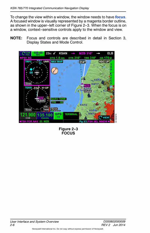
To change the view within a window, the window needs to have focus.A focused window is visually represented by a magenta border outline,as shown in the upper--left corner of Figure 2--3. When the focus is ona window, context--sensitive controls apply to the window and view.
NOTE: Focus and controls are described in detail in Section 3,Display States and Mode Control.
Figure 2--3FOCUS

KSN 765/770 Integrated Communication Navigation Display
D200802000009REV 2 Jun 2014 2-7
User Interface and System Overview
Honeywell International Inc. Do not copy without express permission of Honeywell.
USER CONTROLS
TheKSN765/770 is controlled througha combination of various knobs,dedicated bezel keys, bezel softkeys, touchscreen buttons, aninteractive touchscreen, and keypads. This section provides anintroduction to the controls of the KSN 765/770. The individualfunctionalities are described in detail later in the guide. The KSN 770is shown in Figure 2--4.
Figure 2--4KSN 770 User Controls
The KSN 770 features the following controls:
D Volume Knob
D Radio Control Knob
D Joystick Knob
D Dedicated Bezel Keys
— Zoom- In/+ Bezel Key— Zoom- Out/- Bezel Key

KSN 765/770 Integrated Communication Navigation Display
D200802000009REV 2 Jun 2014
User Interface and System Overview2-8
Honeywell International Inc. Do not copy without express permission of Honeywell.
— Frequency Swap Bezel Key— Direct- To Bezel Key— FMS Bezel Key— MFD Bezel Key— MENU Bezel Key— PAGE Bezel Key— VIEW Bezel Key
D Bezel Softkeys
D Touchscreen Buttons
D Volume Overlay Control
D Keypads.
NOTES: 1. The KSN 765 shares all of the previously mentionedcontrols of the KSN 770, with the exception of theVolume Knob and the Radio Control Knob.
2. The KSN 765/770 does not have a power button. Theunit powers--on with the aircraft avionics.
Volume Knob (KSN 770 Only)Clockwise rotation of the volume knob increases thevolume and counterclockwise rotation decreases thevolume of the selected radio. Pushing the knob turnsthe squelch/ID on or off. The ID function decodesNAVradio Morse code to display the identifier.
Radio Control KnobRotating the outer knob of the radio control knobtunes the selected radio standby megahertz (MHz)frequency (the digits to the left of the decimal point).Rotating the inner knob tunes the selected radiostandby kilohertz (kHz) frequency (the digits to theright of the decimal point). Pushing the knob togglesthe COM and NAV frequencies.
Joystick KnobThe joystick knob provides a rotationcontrol, push function, and a togglefunction. This control can be used forpanning, scrolling, data input, andselecting items.

KSN 765/770 Integrated Communication Navigation Display
D200802000009REV 2 Jun 2014 2-9
User Interface and System Overview
Honeywell International Inc. Do not copy without express permission of Honeywell.
Dedicated Bezel Keys
Dedicatedbezel keys have only one function. The followingparagraphsdescribe the dedicated bezel keys on the KSN 765/770.
ZOOM--IN/+ AND ZOOM--OUT/-- BEZEL KEY
When the view within a selected window contains anadjustable range, the range is increased by pushing thezoom--out/-- bezel key and decreased by pushing thezoom--in/+ bezel key. When the menu is displayed, thezoom--in/+ and zoom--out/-- bezel keys are used toincrease and decrease the screen brightness.
FREQUENCY SWAP BEZEL KEY
Pushing the frequency swap bezel key changes thestandby frequency to the active frequency and the activefrequency to the standby frequency. On the KSN 765, thebezel key exists but has no function.
DIRECT--TO BEZEL KEY
Pushing the Direct--To bezel key displays theDIRECT TO pop--up window where the pilot canenter direct routes to flight plan waypoints, airports,NAVAIDs, intersections, and user waypoints.
FMS BEZEL KEY
Pushing the FMS bezel key selects the FMS functionand returns theFMS function to page 1/3with focus onthe window titled HOME.
MFD BEZEL KEY
Pushing the MFD bezel key selects the MFD function.
MENU BEZEL KEY
Pushing the MENU bezel key activates the menu anddisplays a context--sensitive list of MFD functions andFMS function options.
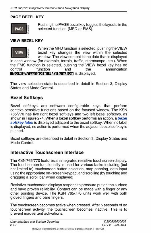
KSN 765/770 Integrated Communication Navigation Display
D200802000009REV 2 Jun 2014
User Interface and System Overview2-10
Honeywell International Inc. Do not copy without express permission of Honeywell.
PAGE BEZEL KEY
Pushing the PAGE bezel key toggles the layouts in theselected function (MFD or FMS).
VIEW BEZEL KEY
When theMFD function is selected, pushing theVIEWbezel key changes the view within the selectedwindow. The view content is the data that is displayed
in each window (for example, terrain, traffic, stormscope, etc.). Whenthe FMS function is selected, pushing the VIEW bezel key has nocontrol function and the annunciationNo VIEW control in FMS function is displayed.
The view selection state is described in detail in Section 3, DisplayStates and Mode Control.
Bezel Softkeys
Bezel softkeys are software configurable keys that performcontext--sensitive functions based on the focused window. The KSN765/770 has five right bezel softkeys and two left bezel softkeys, asshown in Figure 2--4. When a bezel softkey performs an action, a bezelsoftkey label is displayed adjacent to the bezel softkey.When no labelis displayed, no action is performed when the adjacent bezel softkey ispushed.
Bezel softkeys are described in detail in Section 3, Display States andMode Control.
Interactive Touchscreen Interface
TheKSN765/770 features an integrated resistive touchscreen display.The touchscreen functionality is used for various tasks including (butnot limited to) touchscreen button selection, map panning, data inputusing theappropriate on--screen keypad, and scrolling (by touchinganddragging a scroll bar when displayed).
Resistive touchscreen displays respond to pressure put on the surfaceand have proven reliability. Contact can be made with a finger or anyother pointing device. The KSN 765/770 units work well with bothgloved fingers and bare fingers.
The touchscreen becomes active when pressed. After 5 seconds of notouchscreen activity, the touchscreen becomes inactive. This is toprevent inadvertent activations.
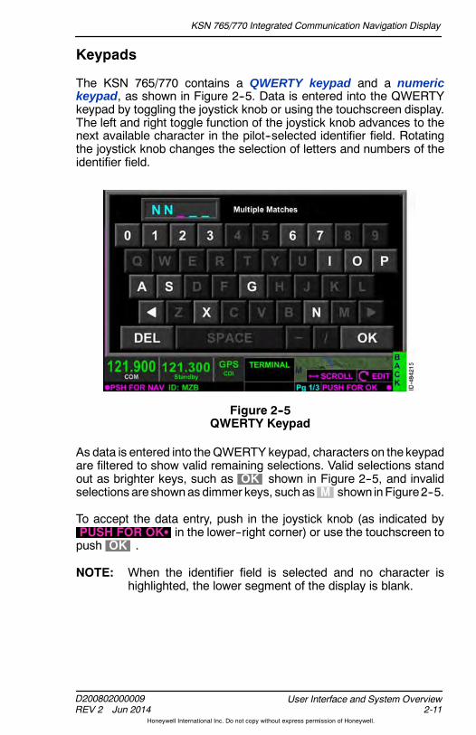
KSN 765/770 Integrated Communication Navigation Display
D200802000009REV 2 Jun 2014 2-11
User Interface and System Overview
Honeywell International Inc. Do not copy without express permission of Honeywell.
Keypads
The KSN 765/770 contains a QWERTY keypad and a numerickeypad, as shown in Figure 2--5. Data is entered into the QWERTYkeypad by toggling the joystick knob or using the touchscreen display.The left and right toggle function of the joystick knob advances to thenext available character in the pilot--selected identifier field. Rotatingthe joystick knob changes the selection of letters and numbers of theidentifier field.
Figure 2--5QWERTY Keypad
As data is entered into theQWERTY keypad, characters on the keypadare filtered to show valid remaining selections. Valid selections standout as brighter keys, such as OK shown in Figure 2--5, and invalidselections are shownas dimmer keys, suchas M shown inFigure2--5.
To accept the data entry, push in the joystick knob (as indicated byPUSH FOR OKS in the lower--right corner) or use the touchscreen topush OK .
NOTE: When the identifier field is selected and no character ishighlighted, the lower segment of the display is blank.

KSN 765/770 Integrated Communication Navigation Display
D200802000009REV 2 Jun 2014
User Interface and System Overview2-12
Honeywell International Inc. Do not copy without express permission of Honeywell.
Scroll Bars
When the amount of text displayed exceeds the displayable limits of thewindow, a scroll bar is displayed to the right of the list, as shown inFigure 2--6.
Figure 2--6Scroll Bars
When the scroll bar is displayed, the text can be scrolled by draggingthe scroll bar using the touchscreen display. The text can also bescrolled using the joystick.
COLOR CONVENTIONColor is used to highlight key information and to help aid the pilot indetermining editable and non--editable states of the KSN 765/770.Table 2--1 provides an overview of the KSN 765/770 color convention.
Table 2--1Color Convention
Color Purpose
RED
Used to indicate temporary flight restrictions (TFRs),weather areas, terrain, obstructions, and warningannunciations that require immediate pilotrecognition. Also used as the strike through color fordatalink weather age annunciations and WX--500rate annunciators when failures occur.
AMBER
Used to indicate weather, traffic, terrain,obstructions, caution annunciations and failureannunciations that require immediate pilotawareness.

KSN 765/770 Integrated Communication Navigation Display
D200802000009REV 2 Jun 2014 2-13
User Interface and System Overview
Honeywell International Inc. Do not copy without express permission of Honeywell.
Table 2--1 (cont)Color Convention
Color Purpose
MAGENTAUsed to identify the selected window, active controlfunctions, depicting navigation map features, theactiveGPSnavigation leg, weather, and terraindata.
CYANUsed to indicate inactive control functions and fordepicting the track line, terrain data, traffic data, andweather data.
GREEN
Used for navigation maps features, weather data,terrain and obstruction data, navigation informationand mode data related to or provided by thenavigation source (i.e., navigation deviations orequipment operating modes).
DARK BLUE Used with saturated green to show the status ofsoftkeys.
SATURATEDGREEN
Used with dark blue to show the status of softkeysand declutter level. Also used to show some primarynavigation information, NAV ID, and GPS modes(black background) and the active COM or NAVfrequency (gray background).
WHITE Used to indicate terrain data and general informationand menu items that are selectable for editing.
GRAY Used to showmenu items that are not selectable forediting.
BLUE Used to indicate weather data and navigation mapfeatures.
BROWN Used to indicate navigation map features.
The following paragraphs describe of Warnings, Cautions, and Notesused throughout the guide.

KSN 765/770 Integrated Communication Navigation Display
D200802000009REV 2 Jun 2014
User Interface and System Overview2-14
Honeywell International Inc. Do not copy without express permission of Honeywell.
WARNING
INDICATES A CRUCIAL OPERATING PROCEDURE THAT, IFNOT STRICTLYOBSERVED, COULDRESULT IN INJURYTO,ORDEATH OF, PERSONNEL OR LONG TERM HEALTH HAZARDS.INDICATES THE POSSIBLE NEED FOR IMMEDIATECORRECTIVE ACTION.
CAUTION
INDICATES AN ESSENTIAL OPERATING PROCEDURE THAT, IFNOT STRICTLY OBSERVED, COULD RESULT IN DAMAGE TO,OR DESTRUCTION OF, EQUIPMENT. INDICATES THEPOSSIBLE NEED FOR FUTURE CORRECTIVE ACTION.
Notes are used to highlight an important operating procedure,condition, or statement.
POP--UP ALERTS
Pop- up alerts are displayed to prompt the pilot for a decision and/oran acknowledgement. Pop--up alerts, shown in Figure 2--7, require aresponse before the system can continue to be used.
NOTE: All pop--up alerts continue to allow control of the CDI, radios(through dedicated knobs and bezel softkeys), volume, andmenu (for brightness).
Figure 2--7Pop--Up Alert

KSN 765/770 Integrated Communication Navigation Display
D200802000009REV 2 Jun 2014 2-15
User Interface and System Overview
Honeywell International Inc. Do not copy without express permission of Honeywell.
Pop--up alerts are prioritized in the following order:
D Traffic advisory
D Missed approach
D Airport diagram
D Manual sequence of altitude legs.
Table 2--2 lists the pop--up alert label colors.
Table 2--2Pop--Up Alert Label Colors
Color Definition
RED TEXT ON BLACKBACKGROUND
Key is active for selection andthe alert condition requiresimmediate pilot recognition.
AMBER TEXT ON BLACKBACKGROUND
Key is active for selection andthe alert condition requiresimmediate pilot awareness.
WHITE TEXT ON GRAYBACKGROUND
Key is active for selection.
Each pop--up alert is described in detail within its respective section.
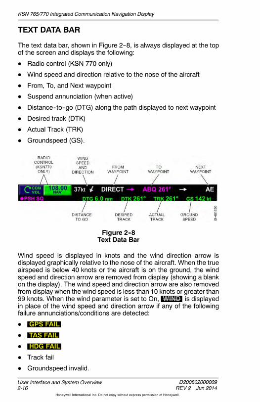
KSN 765/770 Integrated Communication Navigation Display
D200802000009REV 2 Jun 2014
User Interface and System Overview2-16
Honeywell International Inc. Do not copy without express permission of Honeywell.
TEXT DATA BAR
The text data bar, shown in Figure 2--8, is always displayed at the topof the screen and displays the following:
D Radio control (KSN 770 only)
D Wind speed and direction relative to the nose of the aircraft
D From, To, and Next waypoint
D Suspend annunciation (when active)
D Distance--to--go (DTG) along the path displayed to next waypoint
D Desired track (DTK)
D Actual Track (TRK)
D Groundspeed (GS).
Figure 2--8Text Data Bar
Wind speed is displayed in knots and the wind direction arrow isdisplayed graphically relative to the nose of the aircraft. When the trueairspeed is below 40 knots or the aircraft is on the ground, the windspeed and direction arrow are removed from display (showing a blankon the display). The wind speed and direction arrow are also removedfrom display when the wind speed is less than 10 knots or greater than99 knots. When the wind parameter is set to On, WIND is displayedin place of the wind speed and direction arrow if any of the followingfailure annunciations/conditions are detected:
D GPS FAIL
D TAS FAIL
D HDG FAIL
D Track fail
D Groundspeed invalid.
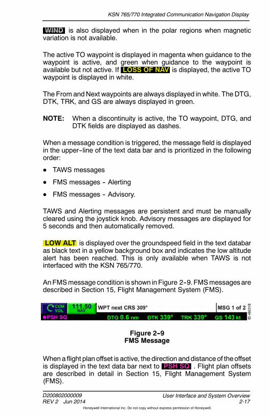
KSN 765/770 Integrated Communication Navigation Display
D200802000009REV 2 Jun 2014 2-17
User Interface and System Overview
Honeywell International Inc. Do not copy without express permission of Honeywell.
WIND is also displayed when in the polar regions when magneticvariation is not available.
The active TO waypoint is displayed in magenta when guidance to thewaypoint is active, and green when guidance to the waypoint isavailable but not active. If LOSS OF NAV is displayed, the active TOwaypoint is displayed in white.
The From andNext waypoints are always displayed in white. TheDTG,DTK, TRK, and GS are always displayed in green.
NOTE: When a discontinuity is active, the TO waypoint, DTG, andDTK fields are displayed as dashes.
When amessage condition is triggered, the message field is displayedin the upper--line of the text data bar and is prioritized in the followingorder:
D TAWS messages
D FMS messages -- Alerting
D FMS messages -- Advisory.
TAWS and Alerting messages are persistent and must be manuallycleared using the joystick knob. Advisory messages are displayed for5 seconds and then automatically removed.
LOW ALT is displayed over the groundspeed field in the text databaras black text in a yellow background box and indicates the low altitudealert has been reached. This is only available when TAWS is notinterfaced with the KSN 765/770.
AnFMSmessage condition is shown inFigure 2--9. FMSmessagesaredescribed in Section 15, Flight Management System (FMS).
Figure 2--9FMS Message
Whena flight planoffset is active, thedirection anddistanceof theoffsetis displayed in the text data bar next to PSH SQ . Flight plan offsetsare described in detail in Section 15, Flight Management System(FMS).

KSN 765/770 Integrated Communication Navigation Display
D200802000009REV 2 Jun 2014
User Interface and System Overview2-18
Honeywell International Inc. Do not copy without express permission of Honeywell.
The SUSPEND annunciation, shown in Figure 2--10, replaces thenext waypoint when in Suspend. Suspend is described in detail inSection 15, Flight Management System (FMS).
Figure 2--10SUSPEND Annunciation
Invalid States
When the active flight plan is not available, dashes are displayed inplace of the following:
D The FROM waypoint
D The TO waypoint
D The next waypoint.
When thedistance, desired track, track, or groundspeed is not availableor is invalid, the numerical value on the text data bar is displayed ingreen dashes ( ------ ).
Distance and actual track are dashed when in dead reckoning mode.
If a loss of navigation condition exists and the GPS position is invalid,the distance, actual track, and groundspeed are dashed.
AIRCRAFT SYMBOL (OWNSHIP)
The ownship symbol provides a visual representation ofthe present position in relation to geography and theactive flight plan.
NOTE: When heading is not available or invalid, and GPS groundtrack is available, the ownship is displayed using GPS trackdata. When both heading and GPS track are not available orinvalid, the ownship symbol is removed from display.
TRUE NORTH ORIENTATION INDICATOR SYMBOL
The truenorth orientation indicator symbol isdisplayedin the upper--left corner of the navigation map display,charts display, and datalink weather display. Theorientation indicator is turned on or off via the menu.
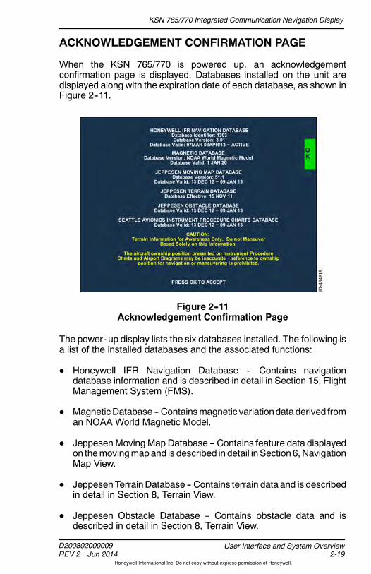
KSN 765/770 Integrated Communication Navigation Display
D200802000009REV 2 Jun 2014 2-19
User Interface and System Overview
Honeywell International Inc. Do not copy without express permission of Honeywell.
ACKNOWLEDGEMENT CONFIRMATION PAGE
When the KSN 765/770 is powered up, an acknowledgementconfirmation page is displayed. Databases installed on the unit aredisplayed along with the expiration date of each database, as shown inFigure 2--11.
Figure 2--11Acknowledgement Confirmation Page
The power--up display lists the six databases installed. The following isa list of the installed databases and the associated functions:
D Honeywell IFR Navigation Database -- Contains navigationdatabase information and is described in detail in Section 15, FlightManagement System (FMS).
D MagneticDatabase -- Containsmagnetic variationdata derived froman NOAA World Magnetic Model.
D JeppesenMoving Map Database -- Contains feature data displayedon themovingmapand is described in detail inSection 6, NavigationMap View.
D JeppesenTerrainDatabase -- Contains terrain data and is describedin detail in Section 8, Terrain View.
D Jeppesen Obstacle Database -- Contains obstacle data and isdescribed in detail in Section 8, Terrain View.

KSN 765/770 Integrated Communication Navigation Display
D200802000009REV 2 Jun 2014
User Interface and System Overview2-20
Honeywell International Inc. Do not copy without express permission of Honeywell.
D Seattle Avionics Instrument ProcedureChartsDatabase -- ContainsNational Aeronautical Charting Office (NACO) charts displayedusing the charts function and is described in detail in Section 7,Charts View.
Terrain and ownship caution messages are also displayed. The OKbezel softkey must be pushed to accept responsibility for all databasesinstalled as well as caution messages, before access to the functionsof the KSN unit is permitted.
NOTE: The KSN 765/770 may display Database Init or Loadingmomentarily after the OK bezel softkey is pushed. Thesystem is ready when the message is no longer displayed.
Expired databases are displayed in amber text with a black backgroundas Database Expired below the database version. Also,One or more Databases are expired is displayed at the bottom ofthe power--up displaywhen any of thedatabases are expired, as shownin Figure 2--12.
Figure 2--12Database Expired and Not Yet Valid
Databases that are not yet valid are displayed in amber text with ablackbackground as Database Not Yet Valid below the database version.
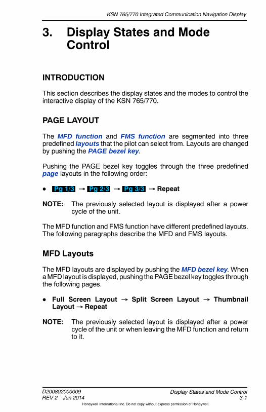
KSN 765/770 Integrated Communication Navigation Display
D200802000009REV 2 Jun 2014 3-1
Display States and Mode Control
Honeywell International Inc. Do not copy without express permission of Honeywell.
3. Display States and ModeControl
INTRODUCTION
This section describes the display states and the modes to control theinteractive display of the KSN 765/770.
PAGE LAYOUT
The MFD function and FMS function are segmented into threepredefined layouts that the pilot can select from. Layouts are changedby pushing the PAGE bezel key.
Pushing the PAGE bezel key toggles through the three predefinedpage layouts in the following order:
D Pg 1/3 Pg 2/3 Pg 3/3 Repeat
NOTE: The previously selected layout is displayed after a powercycle of the unit.
The MFD function and FMS function have different predefined layouts.The following paragraphs describe the MFD and FMS layouts.
MFD Layouts
The MFD layouts are displayed by pushing the MFD bezel key. WhenaMFD layout is displayed, pushing thePAGEbezel key toggles throughthe following pages.
D Full Screen Layout Split Screen Layout ThumbnailLayout Repeat
NOTE: The previously selected layout is displayed after a powercycle of the unit or when leaving the MFD function and returnto it.

KSN 765/770 Integrated Communication Navigation Display
D200802000009REV 2 Jun 2014
Display States and Mode Control3-2
Honeywell International Inc. Do not copy without express permission of Honeywell.
FULL SCREEN LAYOUT
The full screen layout uses the entire MFD to display the variousselectable views. Figure 3--1 shows an example of the full screenlayout in the navigation map view.
Figure 3--1Full Screen Layout
The full screen layout supports the following views in the followingorder:
D Navigation Map ( NAV MAP )
D Datalink Weather ( WX ) 1
D Terrain ( TERR )
D Traffic ( TRFC ) 1
D Stormscope ( STRIKES ) 1
D Charts ( CHARTS ) 1
D Weather Radar ( WX RADAR ) 1
D Terrain Awareness and Warning System ( TAWS ) 1
D GPS Course Deviation Indicator ( GPS CRS DEV ).
NOTE: 1 indicates additional equipment and/or subscription isrequired. When the additional equipment required for theview to function is not installed, or the view is disabled duringinstallation, the view is not displayed and the next availableview is displayed.
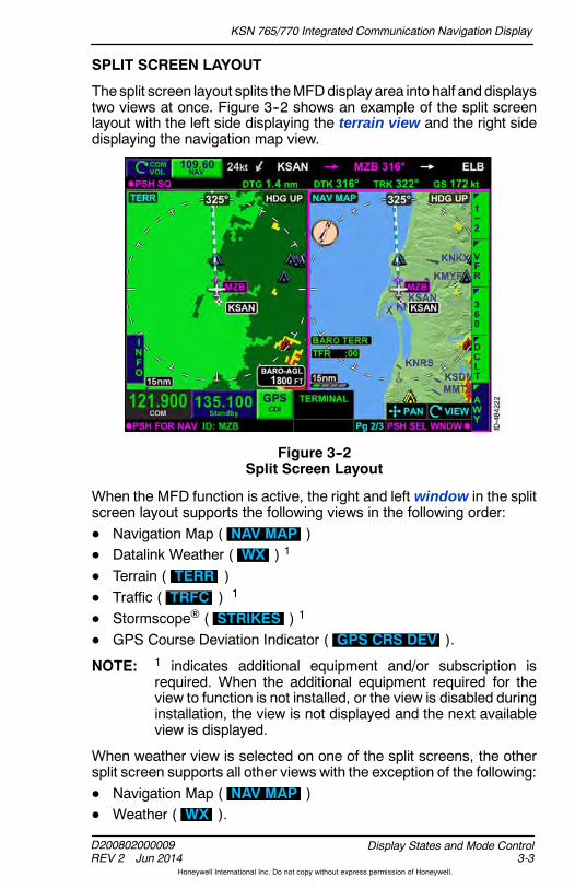
KSN 765/770 Integrated Communication Navigation Display
D200802000009REV 2 Jun 2014 3-3
Display States and Mode Control
Honeywell International Inc. Do not copy without express permission of Honeywell.
SPLIT SCREEN LAYOUT
Thesplit screen layout splits theMFDdisplay area into half anddisplaystwo views at once. Figure 3--2 shows an example of the split screenlayout with the left side displaying the terrain view and the right sidedisplaying the navigation map view.
Figure 3--2Split Screen Layout
When the MFD function is active, the right and left window in the splitscreen layout supports the following views in the following order:D Navigation Map ( NAV MAP )D Datalink Weather ( WX ) 1
D Terrain ( TERR )D Traffic ( TRFC ) 1
D Stormscope ( STRIKES ) 1
D GPS Course Deviation Indicator ( GPS CRS DEV ).
NOTE: 1 indicates additional equipment and/or subscription isrequired. When the additional equipment required for theview to function is not installed, or the view is disabled duringinstallation, the view is not displayed and the next availableview is displayed.
When weather view is selected on one of the split screens, the othersplit screen supports all other views with the exception of the following:D Navigation Map ( NAV MAP )D Weather ( WX ).

KSN 765/770 Integrated Communication Navigation Display
D200802000009REV 2 Jun 2014
Display States and Mode Control3-4
Honeywell International Inc. Do not copy without express permission of Honeywell.
When the navigation map view is selected on one of the split screens,the other split screen supports all other views with the exception of thefollowing:
D Navigation Map ( NAV MAP )
D Weather ( WX ).
THUMBNAIL LAYOUT
The thumbnail layout splits the MFD display area into three areas.Figure 3--3 shows an example of the thumbnail layout with the top--leftthumbnail displaying the traffic view, the lower--left thumbnaildisplaying the terrain view, and the right window displaying thenavigation map view.
Figure 3--3Thumbnail Screen Layout
The top--left window in the thumbnail layout supports the followingviews in the following order:
D Terrain ( TERR )
D Traffic ( TRFC ) 1
D Stormscope ( STRIKES ) 1
D GPS course deviation indicator ( GPS CRS DEV ).

KSN 765/770 Integrated Communication Navigation Display
D200802000009REV 2 Jun 2014 3-5
Display States and Mode Control
Honeywell International Inc. Do not copy without express permission of Honeywell.
The bottom--left window in the thumbnail layout supports the followingviews in the following order:
D Terrain ( TERR )
D Traffic ( TRFC ) 1
D Stormscope ( STRIKES ) 1
D GPS course deviation indicator ( GPS CRS DEV ).
The right window in the thumbnail layout supports the following viewsin the following order:
D Navigation map ( NAV MAP )
D Datalink Weather ( WX ) 1
D Terrain ( TERR )
D Traffic ( TRFC ) 1
D Stormscope ( STRIKES ) 1
D GPS Course Deviation Indicator ( GPS CRS DEV ).
NOTE: 1 indicates additional equipment and/or subscription isrequired. When the additional equipment required for theview to function is not installed, or the view is disabled duringinstallation, the view is not displayed and the next availableview is displayed.
FMS Layouts
The FMS layouts are displayed by pushing the FMS bezel key. WhenaFMS layout is displayed, pushing thePAGE bezel key toggles throughthe following pages.
D FMS Home Page Waypoint Detail Page Utility Page Repeat
Alternating views within the FMS function pages is not permitted. TheFMS function is described in detail in Section 15, Flight ManagementSystem (FMS).
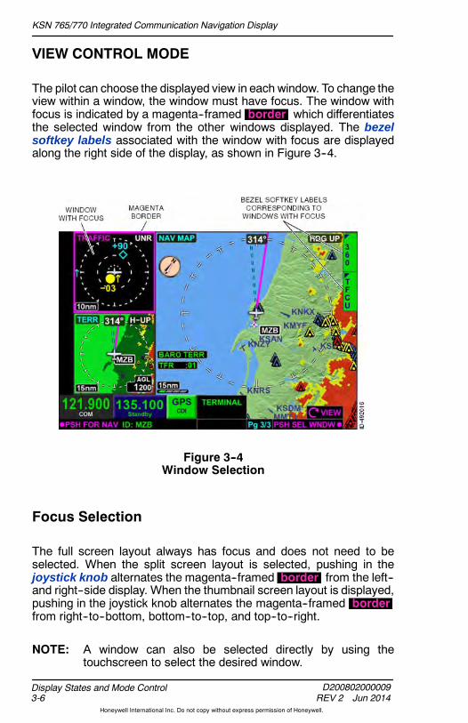
KSN 765/770 Integrated Communication Navigation Display
D200802000009REV 2 Jun 2014
Display States and Mode Control3-6
Honeywell International Inc. Do not copy without express permission of Honeywell.
VIEW CONTROL MODE
The pilot can choose the displayed view in each window. To change theview within a window, the window must have focus. The window withfocus is indicated by a magenta--framed border which differentiatesthe selected window from the other windows displayed. The bezelsoftkey labels associated with the window with focus are displayedalong the right side of the display, as shown in Figure 3--4.
Figure 3--4Window Selection
Focus Selection
The full screen layout always has focus and does not need to beselected. When the split screen layout is selected, pushing in thejoystick knob alternates the magenta--framed border from the left--and right--side display. When the thumbnail screen layout is displayed,pushing in the joystick knob alternates the magenta--framed borderfrom right--to--bottom, bottom--to--top, and top--to--right.
NOTE: A window can also be selected directly by using thetouchscreen to select the desired window.
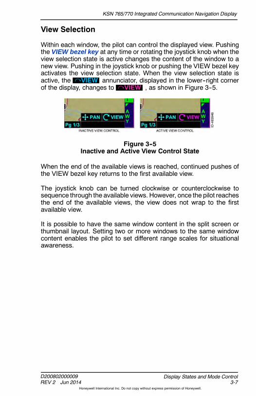
KSN 765/770 Integrated Communication Navigation Display
D200802000009REV 2 Jun 2014 3-7
Display States and Mode Control
Honeywell International Inc. Do not copy without express permission of Honeywell.
View Selection
Within each window, the pilot can control the displayed view. Pushingthe VIEW bezel key at any time or rotating the joystick knob when theview selection state is active changes the content of the window to anew view. Pushing in the joystick knob or pushing the VIEW bezel keyactivates the view selection state. When the view selection state isactive, the VIEW annunciator, displayed in the lower--right cornerof the display, changes to VIEW , as shown in Figure 3--5.
Figure 3--5Inactive and Active View Control State
When the end of the available views is reached, continued pushes ofthe VIEW bezel key returns to the first available view.
The joystick knob can be turned clockwise or counterclockwise tosequence through the available views. However, once the pilot reachesthe end of the available views, the view does not wrap to the firstavailable view.
It is possible to have the same window content in the split screen orthumbnail layout. Setting two or more windows to the same windowcontent enables the pilot to set different range scales for situationalawareness.
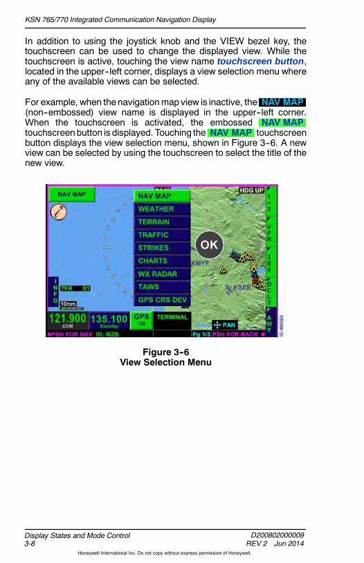
KSN 765/770 Integrated Communication Navigation Display
D200802000009REV 2 Jun 2014
Display States and Mode Control3-8
Honeywell International Inc. Do not copy without express permission of Honeywell.
In addition to using the joystick knob and the VIEW bezel key, thetouchscreen can be used to change the displayed view. While thetouchscreen is active, touching the view name touchscreen button,located in the upper--left corner, displays a view selection menu whereany of the available views can be selected.
For example, when thenavigationmapview is inactive, the NAV MAP(non--embossed) view name is displayed in the upper--left corner.When the touchscreen is activated, the embossed NAV MAPtouchscreenbutton is displayed. Touching the NAV MAP touchscreenbutton displays the view selection menu, shown in Figure 3--6. A newview can be selected by using the touchscreen to select the title of thenew view.
Figure 3--6View Selection Menu
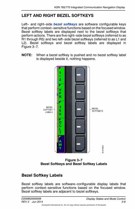
KSN 765/770 Integrated Communication Navigation Display
D200802000009REV 2 Jun 2014 3-9
Display States and Mode Control
Honeywell International Inc. Do not copy without express permission of Honeywell.
LEFT AND RIGHT BEZEL SOFTKEYS
Left-- and right--side bezel softkeys are software configurable keysthat perform context--sensitive functions based on the focusedwindow.Bezel softkey labels are displayed next to the bezel softkeys thatperform actions. There are five right--side bezel softkeys (referred to asR1 through R5) and two left--side bezel softkeys (referred to as L1 andL2). Bezel softkeys and bezel softkey labels are displayed inFigure 3--7.
NOTE: When a bezel softkey is pushed and no bezel softkey labelis displayed beside it, nothing happens.
Figure 3--7Bezel Softkeys and Bezel Softkey Labels
Bezel Softkey Labels
Bezel softkey labels are software--configurable display labels thatperform context--sensitive functions based on the focused window.Bezel softkey labels are adjacent to bezel softkeys.

KSN 765/770 Integrated Communication Navigation Display
D200802000009REV 2 Jun 2014
Display States and Mode Control3-10
Honeywell International Inc. Do not copy without express permission of Honeywell.
Active/Inactive Bezel Softkey Labels
When a bezel softkey label is displayed as blue text on a greenbackground, that key is active. Opposite that, when a bezel softkeylabel is displayed as green text on a blue background, that key isinactive. For example in Figure 3--8, the 360 view is active and thelegend is inactive, as indicated by the 360 and LGND bezel softkeylabels.
Figure 3--8Bezel Softkey Labels
Some bezel softkey labels contain a triangular tag in the upper--leftcorner, which indicates the label has other options that can be toggledthrough when the adjacent bezel softkey is pushed. For example,pushing the bezel softkey adjacent to the 360 bezel softkey labeltoggles to the ARC bezel softkey label.

KSN 765/770 Integrated Communication Navigation Display
D200802000009REV 2 Jun 2014 3-11
Display States and Mode Control
Honeywell International Inc. Do not copy without express permission of Honeywell.
Touchscreen Buttons
Touchscreen buttons are touchsensitive and can be activated bytapping with a finger, stylus, orother pointing device. When a
touchscreen button is available for selection, the touchscreen buttonhas a raised, embossed border. The standby frequency and CDInavigation source indicator shown here are examples of touchscreenbuttons.
The touchscreen is inactive until pressed. This is to prevent inadvertentactivations.When the touchscreen is active, some touchscreenbuttonsbecome embossed and available for selection, such as the view name.
After 5 seconds of not being touched, the view name or associateddropdown menu becomes inactive.
PANNING
The KSN 765/770 has the capability of panning the displayed view tothe left, right, up, or down for the following MFD function views:
D Navigation map view
D Weather view
D Charts view.

KSN 765/770 Integrated Communication Navigation Display
D200802000009REV 3 Nov 2014
Display States and Mode Control3-12
Honeywell International Inc. Do not copy without express permission of Honeywell.
Panning View Control Mode
When in navigation map view, weather view, or charts view, panning isactivated by momentarily pushing the joystick knob in any direction.Panningmode is indicated by amagenta PAN symbol displayed in thelower--right corner of the display and PAN MODE displayed in theupper--center of the navigation map display, as shown in Figure 3--9.
NOTE: PAN MODE is displayed in the upper--right corner for chartsview and weather view.
Figure 3--9Panning Activated Navigation Map Display
When panning is activated, the navigation map, weather, and chartsdisplay freeze in the last orientation and do not move to reflect changesin aircraft heading. The ownship symbol continues to orientate withaircraft heading or track. Caution should be used when panning andmaneuvering to avoid potential disorientation.
When the panning is activated, PSH FOR BACKS and Zoom aredisplayed in the lower--right corner to indicate zoom can be controlledby rotating the joystick knob. Also, LOCKED is displayed below thetrue north orientation indicator symbol, which reminds the pilot thatwhen in panning mode, the display freezes in the last orientation anddoes not move to reflect changes in aircraft heading.
NOTE: Whenpanning is activated, the truenorth orientation indicatoris displayed, even when selected off in the menu.
When panning is activated, the view is centered when the zoom- in/+or zoom- out/- bezel key is pushed or the joystick is rotated to zoomin and out on the location of the cursor.

KSN 765/770 Integrated Communication Navigation Display
D200802000009REV 2 Jun 2014 3-13
Display States and Mode Control
Honeywell International Inc. Do not copy without express permission of Honeywell.
When panning is active, any of the following actions disables panning:
D Pushing the PAGE bezel key
D Pushing the VIEW bezel key
D Pushing in the joystick knob.
When panning becomes inactive, the ownship symbol becomescenteredwithin thewindow.When inactive, VIEW is displayed in thelower--right corner of the display.
FAILURE/STATUS ANNUNCIATIONS
Failure/status annunciations areprovided in the lower--centerdisplay window (shown here asGPS FAIL ). When no failureannunciations are detected, a
black background box is in the lower window. When multiple failureannunciations are detected, the KSN765/770 will alternate between alldetected failure annunciations.
The following failure/status annunciations are provided in thelower--center display window of the KSN:
D GPS FAIL
D GPS ACQ (Acquisition)
D LOI (Loss of Integrity)
D FMS INOP
D INOP FAN
D OVER TEMP
D STUCK MIC
D XMIT FAIL
D ALT FAIL
D HDG FAIL
D TAS FAIL
D RAIM FAIL
D NAV DB FAIL .
NOTE: STUCK MIC and XMIT FAIL annunciations are described indetail in Section 5, KSN 770 Radio.

KSN 765/770 Integrated Communication Navigation Display
D200802000009REV 2 Jun 2014
Display States and Mode Control3-14
Honeywell International Inc. Do not copy without express permission of Honeywell.
GPS Failure Annunciation
Within 1 second of the internal GPS sensor failing, malfunctioning, orbecoming invalid, the amber failure annunciation GPS FAIL isdisplayed. If the failure persists, this condition must bechecked/repaired before next flight.
All system functions relying on GPS position will be unavailable,including:D FMS navigation, approach, and guidance capability (use an
alternate navigation system)D Terrain awarenessD Map, overlay, and sensor views based onGPS position and/or trackD Wind estimates.
GPS Acquisition Status Annunciation
When an insufficient number of GPS satellites for a valid solutioncannot be tracked by the receiver, the GPS ACQ annunciation isdisplayed. If the system is in the en route phase of flight when thisoccurs, the FMS will transition to dead reckoning operation. All othersystem functions of GPS datawill treat this the same as a GPS FAIL .
Ensure that theGPSantennahas a clear viewof the sky. If the conditionpersists, this condition must be checked/repaired before next flight.
GPS Loss of Integrity Status Annunciation
The loss of integrity ( LOI ) annunciation indicates that satellitecoverage is insufficient to pass built--in integrity monitoring testsapplicable to the phase of flight. Another approach or alternatenavigation system may have to be used. Monitor the GPS positionusing alternate sources.
FMS Failure Annunciation
An FMS INOP annunciation is displayed when the internal FMS fails,malfunctions, or becomes inoperative. The ownship symbol is removedand all flight plan legs are displayed in white (no active legs) when thiscondition exists. The KSN can no longer be used fornavigation/approach and may require servicing. The GPS function isstill available for other system functions.
Fan Failure Annunciation
An amber INOP FAN annunciation is displayed when one or both ofthe internal fans fails. No immediate action is required but it should berepaired before next flight.

KSN 765/770 Integrated Communication Navigation Display
D200802000009REV 2 Jun 2014 3-15
Display States and Mode Control
Honeywell International Inc. Do not copy without express permission of Honeywell.
Over Temp Status Annunciation
An amber OVER TEMP annunciation is displayed when the internaltemperature of the unit exceeds the predefined limit. No immediateaction is required but it is recommend to manually lower displaybrightness, and theuseof KSNshould be limited to 30minutes after thismessage is displayed and may require servicing.
Altitude Failure Annunciation
An amber ALT FAIL annunciation is displayed when configured toreceive baro--corrected altitude data and the altitude source is notdetected or the altitude data is invalid. The following modes andinformation will not be available when ALT FAIL is annunciated:D FMS legs with altitude terminated transitions must be manually
sequencedD Terrain awareness will annunciate use of GPS altitude.
If the condition persists, this conditionmust be checked/repairedbeforenext flight.
Heading Failure Annunciation
An amber HDG FAIL annunciation is displayed when configured toreceive heading data and the heading source is not detected or theheading data is invalid. When HDG FAIL is displayed, the followingmodes and information are not available:D Heading Up Map viewsD Flight Plan overlays on WX Radar view.
If the condition persists, this conditionmust be checked/repairedbeforenext flight.
True Air Speed (TAS) Failure Annunciation
When configured to receive TAS data and the TAS source is notdetected or the TAS data is invalid, the TAS FAIL annunciation isdisplayed. If TAS is not available, the estimatedWind Vector will not beshown.
If the condition persists, this conditionmust be checked/repairedbeforenext flight.
Receiver Autonomous Integrity Monitoring (RAIM)Failure Annunciation
When a RAIM ranging fault is detected, the RAIM FAIL annunciationis displayed.

KSN 765/770 Integrated Communication Navigation Display
D200802000009REV 2 Jun 2014
Display States and Mode Control3-16
Honeywell International Inc. Do not copy without express permission of Honeywell.
Navigation Database (NAV DB) Failure Annunciation
When a navigation database fail condition is detected, theNAV DB FAIL annunciation is displayed.
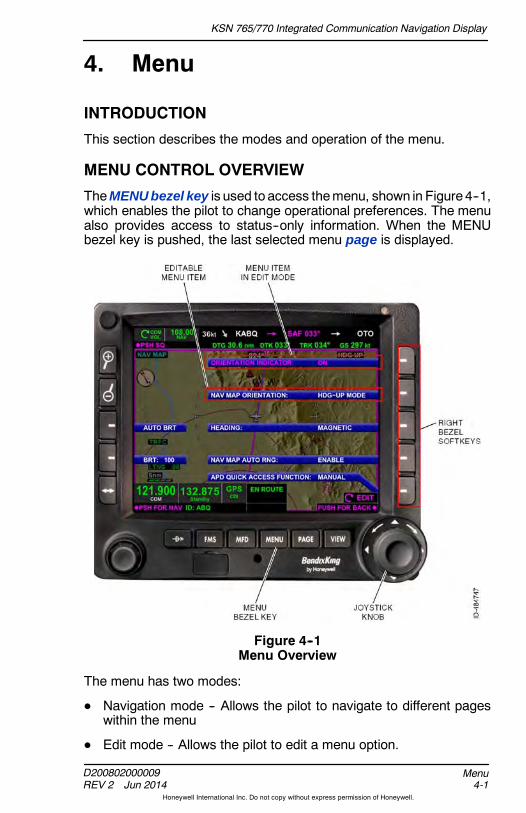
KSN 765/770 Integrated Communication Navigation Display
D200802000009REV 2 Jun 2014 4-1
Menu
Honeywell International Inc. Do not copy without express permission of Honeywell.
4. Menu
INTRODUCTION
This section describes the modes and operation of the menu.
MENU CONTROL OVERVIEW
TheMENU bezel key is used to access themenu, shown in Figure 4--1,which enables the pilot to change operational preferences. The menualso provides access to status--only information. When the MENUbezel key is pushed, the last selected menu page is displayed.
Figure 4--1Menu Overview
The menu has two modes:
D Navigation mode -- Allows the pilot to navigate to different pageswithin the menu
D Edit mode -- Allows the pilot to edit a menu option.
KSN 765/770 Integrated Communication Navigation Display
D200802000009REV 2 Jun 2014
Menu4-2
Honeywell International Inc. Do not copy without express permission of Honeywell.
Navigation mode is the default menu state. In navigation mode,navigation between the six menu pages is accomplishedby rotating thejoystick knob. Navigation mode is indicated by Menu Page #/6being displayed in the bottom--right corner.
NOTE: The menu cannot be operated or controlled using thetouchscreen.
A menu list item becomes active for editing when the correspondingbezel softkey is pushed. Only onemenu item can be active for editingat any time. Edit mode is indicated by EDIT , shown in FIgure 4--1,being displayed in the bottom--right corner in the place ofMenu Page #/6 .
In edit mode, adjusting the editable values is accomplished with thejoystick knob. Also when in edit mode, scrolling between menu pagesis not possible.
Pushing the MENU bezel key or pushing anywhere on the touchscreenremoves the menu overlay from the display.
General Menu Operation
When edit mode is inactive, Menu Page #/6 is displayed in thelower--right part of the display, where # is the menu page number and6 is the total number of menu pages available.
When edit mode is inactive, rotating the joystick knob navigatesbetween the menu pages. Rotating the joystick knob clockwiseadvances the next menu page and counterclockwise rotation returns tothe prior menu page.
On reaching the end of available menu pages, continued rotation of thejoystick knob does not result in the menu navigation wrapping to thebeginning or end of the menu page list.

KSN 765/770 Integrated Communication Navigation Display
D200802000009REV 2 Jun 2014 4-3
Menu
Honeywell International Inc. Do not copy without express permission of Honeywell.
Menu items editable but not active for editing are displayed as whitetext on a blue background, as shown in Figure 4--2.
Figure 4--2Editable Menu Item
Non--editable or status--only menu items are displayed as green texton a blue background, as shown in Figure 4--3.
Figure 4--3Status Item
Menu items which have been disabled from editing are removed ordisplay in gray text on a blue background, as shown in Figure 4--4.
Figure 4--4Non--Editable Field

KSN 765/770 Integrated Communication Navigation Display
D200802000009REV 2 Jun 2014
Menu4-4
Honeywell International Inc. Do not copy without express permission of Honeywell.
Edit Mode Operation
When edit mode is active, the editable value is displayed inmagentaand the magenta EDIT annunciator is displayed in the lower--rightcorner, as shown in Figure 4--5.
Figure 4--5Edit Mode Active
Rotating the joystick knobadjusts theeditablevalue. Continued rotationof the joystick knob wraps through the available editable menu options.
Pushing the bezel softkey adjacent to the editable value or pushing inthe joystick knob disables the field from editing and exits the edit mode.Pushing the bezel softkey adjacent to a different editable field enablesthat field for editing anddisables thepreviously selected field for editing.
Menu Controls
When theMENUbezel key is pushed, sixmenupages are viewable thatpermit control of various functions and display information that can beuseful to the pilot.
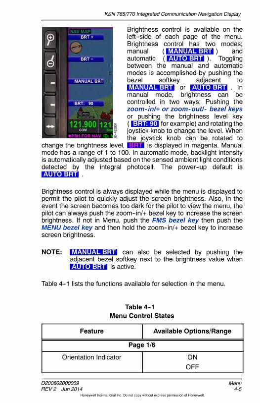
KSN 765/770 Integrated Communication Navigation Display
D200802000009REV 2 Jun 2014 4-5
Menu
Honeywell International Inc. Do not copy without express permission of Honeywell.
Brightness control is available on theleft--side of each page of the menu.Brightness control has two modes;manual ( MANUAL BRT ) andautomatic ( AUTO BRT ). Togglingbetween the manual and automaticmodes is accomplished by pushing thebezel softkey adjacent toMANUAL BRT or AUTO BRT . Inmanual mode, brightness can becontrolled in two ways; Pushing thezoom- in/+ or zoom- out/- bezel keysor pushing the brightness level key( BRT: 90 for example) and rotating thejoystick knob to change the level. Whenthe joystick knob can be rotated to
change the brightness level, BRT is displayed in magenta. Manualmode has a range of 1 to 100. In automatic mode, backlight intensityis automatically adjusted based on the sensed ambient light conditionsdetected by the integral photocell. The power--up default isAUTO BRT .
Brightness control is always displayed while the menu is displayed topermit the pilot to quickly adjust the screen brightness. Also, in theevent the screen becomes too dark for the pilot to view the menu, thepilot can always push the zoom--in/+ bezel key to increase the screenbrightness. If not in Menu, push the FMS bezel key then push theMENU bezel key and then hold the zoom--in/+ bezel key to increasescreen brightness.
NOTE: MANUAL BRT can also be selected by pushing theadjacent bezel softkey next to the brightness value whenAUTO BRT is active.
Table 4--1 lists the functions available for selection in the menu.
Table 4--1Menu Control States
Feature Available Options/Range
Page 1/6
Orientation Indicator ONOFF

KSN 765/770 Integrated Communication Navigation Display
D200802000009REV 2 Jun 2014
Menu4-6
Honeywell International Inc. Do not copy without express permission of Honeywell.
Table 4--1 (cont)Menu Control States
Feature Available Options/Range
Nav Map Orientation N--UP MODEHDG--UP MODETRK--UP MODE
Heading MAGNETICTRUE
When TRUE is selected (ormagnetic variation is invalid orunreliable), the TRUE values for
course, heading, and trackvalues are displayed with a T tothe right of the value, as shown
in Figure 4--6.When magnetic heading is notavailable or invalid, this option isdisplayed in gray and is set to
TRUE.
Nav Map Auto Range DISABLEENABLE
Airport Diagram (APD) QuickAccess Function
OFFAUTO
MANUALWhen charts is not enabled, thisfeature is displayed in gray and
is disabled.
Page 2/6
Nav Map Controlled Airspace(Class A, B,C, D, F, and G areincluded in this selection)
OFFAUTO
Nav Map Special Use Airspace(Prohibited and TFRs are not
included in this selection as theyare always ON regardless ordeclutter or range settings)
OFFAUTO
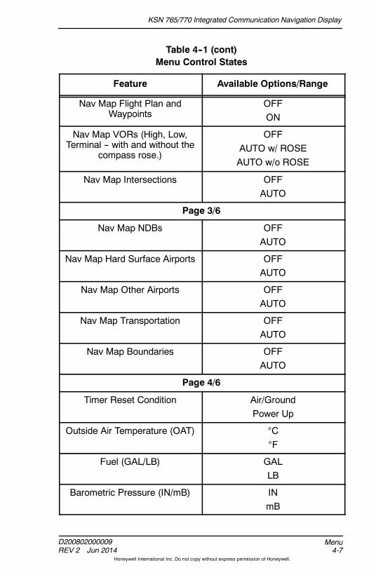
KSN 765/770 Integrated Communication Navigation Display
D200802000009REV 2 Jun 2014 4-7
Menu
Honeywell International Inc. Do not copy without express permission of Honeywell.
Table 4--1 (cont)Menu Control States
Feature Available Options/Range
Nav Map Flight Plan andWaypoints
OFFON
Nav Map VORs (High, Low,Terminal -- with and without the
compass rose.)
OFFAUTO w/ ROSEAUTO w/o ROSE
Nav Map Intersections OFFAUTO
Page 3/6
Nav Map NDBs OFFAUTO
Nav Map Hard Surface Airports OFFAUTO
Nav Map Other Airports OFFAUTO
Nav Map Transportation OFFAUTO
Nav Map Boundaries OFFAUTO
Page 4/6
Timer Reset Condition Air/GroundPower Up
Outside Air Temperature (OAT) CF
Fuel (GAL/LB) GALLB
Barometric Pressure (IN/mB) INmB
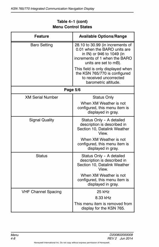
KSN 765/770 Integrated Communication Navigation Display
D200802000009REV 2 Jun 2014
Menu4-8
Honeywell International Inc. Do not copy without express permission of Honeywell.
Table 4--1 (cont)Menu Control States
Feature Available Options/Range
Baro Setting 28.10 to 30.99 (in increments of0.01 when the BARO units are
in IN) or 946 to 1049 (inincrements of 1 when the BARO
units are set to mB).This field is only displayed whenthe KSN 765/770 is configured
to received uncorrectedbarometric altitude.
Page 5/6
XM Serial Number Status OnlyWhen XM Weather is not
configured, this menu item isdisplayed in gray.
Signal Quality Status Only -- A detaileddescription is described in
Section 10, Datalink WeatherView.
When XM Weather is notconfigured, this menu item is
displayed in gray.
Status Status Only -- A detaileddescription is described in
Section 10, Datalink WeatherView.
When XM Weather is notconfigured, this menu item is
displayed in gray.
VHF Channel Spacing 25 kHz8.33 kHz
This menu item is removed fromdisplay for the KSN 765.

KSN 765/770 Integrated Communication Navigation Display
D200802000009REV 2 Jun 2014 4-9
Menu
Honeywell International Inc. Do not copy without express permission of Honeywell.
Table 4--1 (cont)Menu Control States
Feature Available Options/Range
Missed Approach Alert DISABLEENABLE
Only displayed when the unit isconfigured for this field to be
editable.
Page 6/6
Selected Navigation DatabaseStatus
Status Only
Push To Change NAV DB Cycle Provides Action
Hold For System Info Pushing and holding the bezelsoftkey displays a SYSTEM
INFO page. The SYSTEM INFOpage displays detailed systeminformation including the unitserial number and softwareversion with part numbers.
Information for the HoneywellIFR navigation database, chartsdatabase, and terrain database
are displayed also.
Hold For Discrete AnnunciatorTest
When pushed and held, theKSN 765/770 activates the
connected discreteannunciators.

KSN 765/770 Integrated Communication Navigation Display
D200802000009REV 2 Jun 2014
Menu4-10
Honeywell International Inc. Do not copy without express permission of Honeywell.
When TRUE is selected (or magnetic variation is invalid or unreliable),the TRUE values for course, heading, and track are displayed with a Tto the right of the value, as shown in Figure 4--6.
Figure 4--6True Selected for NAV Map Orientation
DISCRETE ANNUNCIATOR TEST
When the HOLD FOR DISCRETE ANNUNCIATOR TEST menuitem is held, the following remote annunciations will be lit if installedduring the annunciator test:
D LNAV Approach Activate
D LNAV/VNAV Approach Activate
D LPV Approach Activate
D LP Approach Activate
D Dead Reckoning
D CDI GPS
D LOI
D Message
D Suspend
D CDI VLOC
D Waypoint.

KSN 765/770 Integrated Communication Navigation Display
D200802000009REV 2 Jun 2014 5-1
KSN 770 Radio
Honeywell International Inc. Do not copy without express permission of Honeywell.
5. KSN 770 Radio
INTRODUCTIONThe bezel softkeys, knobs, and touchscreen are used to control andtune the internal navigation and communication radios.
NOTE: The radio control mode is not supported by the KSN 765.
VOLUME CONTROLThe pilot controls the communication and navigation volume with thevolume knob, shown in Figure 5--1. When COM frequencies aredisplayed in the radio tuning window, rotating the volume knob controlsthe COM volume. When NAV frequencies are displayed in the radiotuning window, rotating the volume knob controls the NAV volume.Clockwise rotation of the volume knob increases the volume of theselected radio. Counterclockwise rotation of the volume knobdecreases the volume of the selected radio.
Figure 5--1KSN 770 Radio Overview
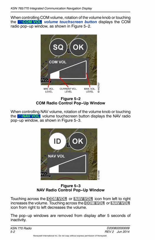
KSN 765/770 Integrated Communication Navigation Display
D200802000009REV 2 Jun 2014
KSN 770 Radio5-2
Honeywell International Inc. Do not copy without express permission of Honeywell.
When controlling COM volume, rotation of the volume knob or touchingthe COM VOL volume touchscreen button displays the COMradio pop--up window, as shown in Figure 5--2.
Figure 5--2COM Radio Control Pop--Up Window
When controlling NAV volume, rotation of the volume knob or touchingthe NAV VOL volume touchscreen button displays the NAV radiopop--up window, as shown in Figure 5--3.
Figure 5--3NAV Radio Control Pop--Up Window
Touching across the COM VOL or NAV VOL icon from left to rightincreases the volume. Touching across the COM VOL or NAV VOLicon from right to left decreases the volume.
The pop--up windows are removed from display after 5 seconds ofinactivity.

KSN 765/770 Integrated Communication Navigation Display
D200802000009REV 2 Jun 2014 5-3
KSN 770 Radio
Honeywell International Inc. Do not copy without express permission of Honeywell.
COM SQUELCH AND NAV IDENTIFIER CONTROL
When the communication radio is the selected source, SPSH SQ isdisplayed in the upper--left corner of the display. Pushing the volumeknob when SPSH SQ is displayed toggles the communication radioautomatic squelch state between inactive to active, as shown inFigure 5--4.
NOTE: The squelch can also be toggled betweenmute and un--mutewhen the COM radio control pop--up window is displayed,shown in Figure 5--2.
Figure 5--4Squelch On and Off
When automatic squelch is inactive, SQ is displayed in the activeCOM frequency window. When automatic squelch is active, SQ isremoved from display in the active COM frequency window.
When the communication system is receiving, a green R is displayedbelow the active frequency. When the system is transmitting, a greenT is displayed below the active frequency, as shown in Figure 5--4.
When the navigation radio is the selected source, SPSH ID isdisplayed in the upper--left corner of the display. Pushing the volumeknob when SPSH ID is displayed toggles the navigation identifierbetween off to on, as shown in Figure 5--5.
NOTE: The internal navigation identifier can alsobe toggledbetweenon and off when the NAV radio control pop--up window isdisplayed, shown in Figure 5--3.
Figure 5--5NAV Ident On and Off

KSN 765/770 Integrated Communication Navigation Display
D200802000009REV 2 Jun 2014
KSN 770 Radio5-4
Honeywell International Inc. Do not copy without express permission of Honeywell.
When the navigation identifier is OFF, the NAVAID is not automaticallytuned, as indicated by ID: off under the standby frequency.
When theNAVAID radio audio received from the tuned localizer or VORis sufficient and the navigation identifier isON, the identifier is displayedunder the standby frequency next to ID: , as shown in Figure 5--5.When theNAVAID radio audio received from the tuned localizer or VORis not sufficient, only ID: is displayed and the identifier field is blank.
The power--up default is NAV IDENT filter ON.
The COM/NAV radio control pop--up window displays the squelch andidentifier states, shown in Figure 5--6. The squelch and identifier statescan be controlled using the touchscreen.
Figure 5--6COM/NAV Pop--Up Window States
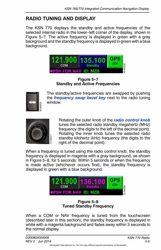
KSN 765/770 Integrated Communication Navigation Display
D200802000009REV 2 Jun 2014 5-5
KSN 770 Radio
Honeywell International Inc. Do not copy without express permission of Honeywell.
RADIO TUNING AND DISPLAY
The KSN 770 displays the standby and active frequencies of theselected internal radio in the lower--left corner of the display, shown inFigure 5--7. The active frequency is displayed in green with a graybackground and the standby frequency is displayed in greenwith abluebackground.
Figure 5--7Standby and Active Frequencies
The standby/active frequencies are swapped by pushingthe frequency swap bezel key next to the radio tuningwindow.
Rotating the outer knob of the radio control knobtunes the selected radio standby megahertz (MHz)frequency (the digits to the left of the decimal point).Rotating the inner knob tunes the selected radiostandby kilohertz (kHz) frequency (the digits to theright of the decimal point).
When a frequency is tuned using the radio control knob, the standbyfrequency is displayed in magenta with a gray background, as shownin Figure 5--8, for 5 seconds. Within 5 seconds or when the frequencyis made active (whichever occurs first), the standby frequency isdisplayed in green with a blue background.
Figure 5--8Tuned Standby Frequency
When a COM or NAV frequency is tuned from the touchscreen(described later in this section), the standby frequency is displayed inwhite with a magenta background and fades away within 3 seconds tothe normal display.
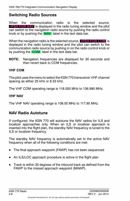
KSN 765/770 Integrated Communication Navigation Display
D200802000009REV 2 Jun 2014
KSN 770 Radio5-6
Honeywell International Inc. Do not copy without express permission of Honeywell.
Switching Radio Sources
When the communication radio is the selected source,SPSH FOR NAV is displayed in the radio tuning window and the pilotcan switch to the navigation radio source by pushing the radio controlknob or by pushing the NAV label in the text data bar.
When the navigation radio is the selected source, SPSH FOR COM isdisplayed in the radio tuning window and the pilot can switch to thecommunication radio source by pushing in on the radio control knob orby pushing the COM label in the text data bar.
NOTE: Navigation frequencies are displayed for 30 seconds andthen revert back to COM frequencies.
VHF COM
Thepilot uses themenu to select theKSN770 transceiver VHF channelspacing as either 25 kHz or 8.33 kHz.
The VHF COM operating range is 118.000 MHz to 136.990 MHz.
VHF NAV
The VHF NAV operating range is 108.00 MHz to 117.95 MHz.
NAV Radio Autotune
If configured, the KSN 770 will autotune the NAV radios for ILS andlocalizer approaches only. When an ILS or localizer approach isinserted into the flight plan, the standby NAV frequency is tuned to theILS or localizer frequency.
The standby NAV frequency is automatically set to the active NAVfrequency when all of the following conditions are met:
D The final approach waypoint (FAWP) has not been sequenced
D An ILS/LOC approach procedure is active in the flight plan
D Track is within 35 degrees of the inbound track as defined from theFAWP to the missed approach waypoint (MAWP).

KSN 765/770 Integrated Communication Navigation Display
D200802000009REV 2 Jun 2014 5-7
KSN 770 Radio
Honeywell International Inc. Do not copy without express permission of Honeywell.
The KSN 770 will automatically switch the CDI selected NAV sourcefrom GPS to VLOC when all of the following conditions are met:
D The FAWP has not been sequenced
D An ILS/LOC approach procedure is active in the flight plan
D Track is within 35 degrees of the inbound track as defined from theFAWP to the MAWP
D Track is within 10 degrees of the desired track.
Touchscreen Tuning
Pushing the on--screen standby COM frequency displays the radiotuning pop--up window shown in Figure 5--9.
NOTE: Pushing the on--screen standby NAV frequency displays thesame pop--up window without the CH bezel softkey label.
Figure 5--9Radio Frequency Tuning Pop--Up Window
The radio frequency is entered by pushing the touchscreen numbers onthe radio frequency pop--up window. As the frequency is selected, theremaining valid frequency values remain available for selection. Theremaining invalid frequency values are grayed--out andnot available forselection.
Pushing the left arrow touchscreen softkey deletes the last selectedfrequency value without removing the radio tuning pop--up window.

KSN 765/770 Integrated Communication Navigation Display
D200802000009REV 2 Jun 2014
KSN 770 Radio5-8
Honeywell International Inc. Do not copy without express permission of Honeywell.
The radio tuning pop--up window is removed by pushing OK on thetouchscreen, pushing the BACK bezel softkey, touching outside thepop--up window display area, or pushing the radio control knob.
Stored Frequency List
To view or edit a stored COM frequency, push the on--screen standbyCOM frequency field in the lower--left corner of the display, then pushthe CH bezel softkey. The stored frequency list, shown in Figure 5--10,is then displayed.
Figure 5--10Stored Frequencies
A stored frequency can be selected from the stored frequency list bypushing in the joystick knob (as indicated by PSH TO SELECTS inthe lower--right corner of the display) or by touching the selectedfrequency on the touchscreen. When this selection is made, thefrequency is placed into the standby frequency field. The storedfrequency window does not close when a stored frequency is entered.Pushing the BACK bezel softkey or touching the touchscreen outsidethe pop--up window display area closes the window.
The stored frequency list supports the selection of the storedcommunication frequencies in the range of 118.000 MHz to136.990 MHz when 8.33 kHz VHF channel spacing is selected (by themenu) and 118.000 MHZ to 136.975 MHz when 25 kHz VHF channelspacing is selected.
NOTE: The stored frequency lists for 8.33 kHz and 25 kHz channelspacingare independent of eachother.Changing thechannelspacing on the menu displays a different stored frequencylist.

KSN 765/770 Integrated Communication Navigation Display
D200802000009REV 2 Jun 2014 5-9
KSN 770 Radio
Honeywell International Inc. Do not copy without express permission of Honeywell.
The EMERGENCY channel has a stored frequency of 121.500, whichcannot be edited.
NOTE: When the EMERGENCY channel is highlighted, the EDITand DEL bezel softkey labels are not displayed.
When a stored frequency is highlighted (not including theEMERGENCY frequency), the EDIT and DEL bezel softkey labelsare displayed. The stored frequency can be edited by pushing theEDIT bezel softkey. Pushing the EDIT bezel softkey activates editmode and displays the EDIT and CNCL bezel softkey labels, asshown in Figure 5--11. The highlighted stored frequency can be editedusing the joystick knob.
Figure 5--11Edit Frequency
When the frequency is set as desired, pushing the EDIT bezel softkeycommits the frequency to memory and exits the edit mode.
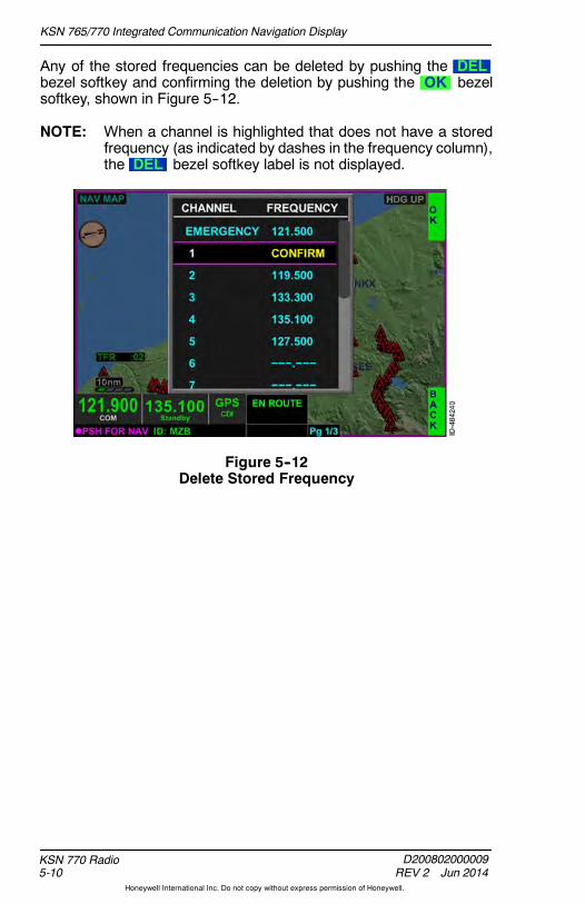
KSN 765/770 Integrated Communication Navigation Display
D200802000009REV 2 Jun 2014
KSN 770 Radio5-10
Honeywell International Inc. Do not copy without express permission of Honeywell.
Any of the stored frequencies can be deleted by pushing the DELbezel softkey and confirming the deletion by pushing the OK bezelsoftkey, shown in Figure 5--12.
NOTE: When a channel is highlighted that does not have a storedfrequency (as indicated by dashes in the frequency column),the DEL bezel softkey label is not displayed.
Figure 5--12Delete Stored Frequency

KSN 765/770 Integrated Communication Navigation Display
D200802000009REV 2 Jun 2014 5-11
KSN 770 Radio
Honeywell International Inc. Do not copy without express permission of Honeywell.
Nearest Airport Frequency Control
Pushing the NRST bezel softkey shown in Figure 5--9, displays theNEAREST FREQUENCIES windowshown inFigure 5--13.When theCOM radios are selected, the nearest airport frequencies are displayedby default.
NOTE: When the NAV radios are selected, the nearest VORs aredisplayed by default.
Figure 5--13Nearest Airport Frequencies
The 20 nearest airport frequencies are displayed within 100 NM(nauticalmiles) from thepresent position, with the closest listed first andthe farthest listed last. The bearing, distance, andETE to the airport aredisplayed next to each of the nearest airports.

KSN 765/770 Integrated Communication Navigation Display
D200802000009REV 2 Jun 2014
KSN 770 Radio5-12
Honeywell International Inc. Do not copy without express permission of Honeywell.
The desired airport is selected from the list of airports by rotating thejoystick knob or using the touchscreen. When the desired airport isselected, pushing in the joystick knob or pushing the touchscreen twicedisplays a list of frequencies for the selected airport, as shown inFigure 5--14.
Figure 5--14Selected Airport COM Frequencies
The frequencies are displayed in the following order: DEPARTURECOMMS, ARRIVAL COMMS, ALL COMMS.
The frequency list is scrolled by rotating the joystick knob or draggingthe scroll bar using the touchscreen. Frequencies are displayed ingreen text on a blue background, similar to the standby frequency in theradio tuning window. The frequency is tuned to the standby frequencyfield by using the touchscreen to select the desired frequency.
The nearest frequencies window does not close when a frequency isentered. Pushing the BACK bezel softkey twice closes the window.

KSN 765/770 Integrated Communication Navigation Display
D200802000009REV 2 Jun 2014 5-13
KSN 770 Radio
Honeywell International Inc. Do not copy without express permission of Honeywell.
Nearest ARTCC Frequency Control
When the NEAREST FREQUENCIES box is displayed, pushing theARTC bezel softkey displays a list of the ARTCC frequencies, asshown in Figure 5--15.
Figure 5--15Nearest ARTCC Frequencies
A frequency is selected by rotating the joystick knob and pushing theknob for selection or by pushing the desired frequency twice on thetouchscreen. When the selection is made, the frequency is entered inthe standby field.
The 20 nearest ARTCC frequencies within 100 NM from the presentposition can be displayed, with the closest listed first and the farthestlisted last.
The nearest frequencies window does not close when a frequency isentered. Pushing the BACK bezel softkey closes the window.
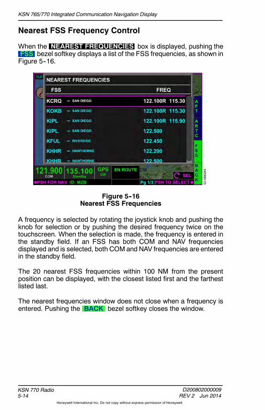
KSN 765/770 Integrated Communication Navigation Display
D200802000009REV 2 Jun 2014
KSN 770 Radio5-14
Honeywell International Inc. Do not copy without express permission of Honeywell.
Nearest FSS Frequency Control
When the NEAREST FREQUENCIES box is displayed, pushing theFSS bezel softkey displays a list of the FSS frequencies, as shown inFigure 5--16.
Figure 5--16Nearest FSS Frequencies
A frequency is selected by rotating the joystick knob and pushing theknob for selection or by pushing the desired frequency twice on thetouchscreen. When the selection is made, the frequency is entered inthe standby field. If an FSS has both COM and NAV frequenciesdisplayed and is selected, both COMand NAV frequencies are enteredin the standby field.
The 20 nearest FSS frequencies within 100 NM from the presentposition can be displayed, with the closest listed first and the farthestlisted last.
The nearest frequencies window does not close when a frequency isentered. Pushing the BACK bezel softkey closes the window.

KSN 765/770 Integrated Communication Navigation Display
D200802000009REV 2 Jun 2014 5-15
KSN 770 Radio
Honeywell International Inc. Do not copy without express permission of Honeywell.
Nearest NAV Frequency Control
Pushing the NRST bezel softkey when the NAV radios are selecteddisplays the NEAREST FREQUENCIES pop--up window, shown inFigure 5--17. Only the nearest VOR frequencies are displayed whenthe navigation radios are selected.
Figure 5--17Nearest VOR Frequencies
A frequency is selected by rotating the joystick knob and pushing theknob for selection or by pushing the desired frequency twice on thetouchscreen. When the selection is made, the frequency is entered inthe standby NAV field.
The 20 nearest VOR frequencies can be displayed within 100 NM fromthe present position, with the closest listed first and the farthest listedlast.
The nearest frequencies window does not close when a frequency isentered. Pushing the BACK softkey closes the window.
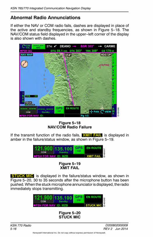
KSN 765/770 Integrated Communication Navigation Display
D200802000009REV 2 Jun 2014
KSN 770 Radio5-16
Honeywell International Inc. Do not copy without express permission of Honeywell.
Abnormal Radio Annunciations
If either the NAV or COM radio fails, dashes are displayed in place ofthe active and standby frequencies, as shown in Figure 5--18. TheNAV/COM status field displayed in the upper--left corner of the displayis also shown with dashes.
Figure 5--18NAV/COM Radio Failure
If the transmit function of the radio fails, XMIT FAIL is displayed inamber in the failure/status window, as shown in Figure 5--19.
Figure 5--19XMIT FAIL
STUCK MIC is displayed in the failure/status window, as shown inFigure 5--20, 30 to 35 seconds after the microphone button has beenpushed.When the stuckmicrophoneannunciator isdisplayed, the radioimmediately stops transmitting.
Figure 5--20STUCK MIC

KSN 765/770 Integrated Communication Navigation Display
D200802000009REV 2 Jun 2014 6-1
Navigation Map View
Honeywell International Inc. Do not copy without express permission of Honeywell.
6. Navigation Map View
INTRODUCTION
This section describes the many navigation functions featured in theKSN 765/770. The navigation map view is customizable to displaysymbols depicting the location of NAVAIDs, intersections, airways,airports, topographic information, boundaries, and FMS flight plans andwaypoints. The map can be displayed in VFR or IFR styles and variousoverlays can be selected using bezel softkeys. The overlays includetraffic, terrain, lightning, and datalink weather.
NOTE: The navigation database valid date range is viewed on theacknowledgement page and the menu, described inSection 4, Menu.
NAVIGATION MAP OVERVIEW
The navigation map view is selected by pushing the MFD bezel keythen pushing the VIEW bezel key or rotating the joystick knob untilthe NAV MAP view, shown in Figure 6--1, is displayed.
Figure 6--1Navigation Map View

KSN 765/770 Integrated Communication Navigation Display
D200802000009REV 2 Jun 2014
Navigation Map View6-2
Honeywell International Inc. Do not copy without express permission of Honeywell.
CAUTION
THE NAVIGATION DATABASES MUST BE UPDATED ON AREGULAR BASIS TO ENSURE THE BEST POSSIBLEACCURACY. DO NOT USE OUTDATED INFORMATION.
The navigation map view initializes the current position or last knownposition if the current position is unavailable following a power cycle.
The navigation map view can be configured todisplay anavigationmap in oneofmanystyles,with various information overlays that can beturned on and off with the bezel softkeys.
NOTE: Display and operation of the bezelsoftkey labels associated withlightning, NEXRAD, and trafficoverlays are optional and requireadditional equipment. When notinstalled, the associated bezelsoftkey labels are not displayed.
The navigation map view has the followingoptions, which are controlled using the bezelsoftkeys along the right--side of the display.
D VFR/IFR -- Configures the map as either avisual flight rules (VFR) or instrument flightrules (IFR) style map.
D 360/ARC -- Configures the map view aseither 360--degree mode (aircraft shown incenter of display) or arc mode (aircraftshown at bottom of display).
D DCLT (Declutter) -- Declutters the map display in a round--robinfashion from HighMedium/HighMedium/Low LowOffRepeat.
D AWY (Airway) -- Configures the airway overlay as either none, low,or high airways.
D TERR (Terrain) -- Toggles the terrain overlay on and off.
D LTNG (Lightning) -- Configures the lightningoverlay asoff, on, strike,and cell. (Optional and requires anexternalWX--500Stormscope.)
KSN 765/770 Integrated Communication Navigation Display
D200802000009REV 2 Jun 2014 6-3
Navigation Map View
Honeywell International Inc. Do not copy without express permission of Honeywell.
D NXRD (NEXRAD) -- Toggles the datalink weather overlay ofNEXRAD on and off. Optional and requires XM WX subscription.
D TRFC (Traffic) -- Configures the traffic overlay as off, normal,unrestricted, above, and below. Optional and requires an externaltraffic sensor.
Details of each of the overlay modes are described later in this section.
The menu can be used to further customize and configure the mapdisplay. The pilot can customize the navigation map to consist of thefollowing symbols:
D Navigational aids (NAVAIDs)
D Intersections
D Airports
D Topographic information
D Cultural data
D Boundaries
D FMS flight plan and waypoints.
Themap has three user--selected displaymodes that are chosen usingthe menu:
1. North--up -- True north up (N--UP MODE).
2. Heading--up -- Magnetic heading up (HDG--UP MODE) (ifconfigured).
3. Track--up -- Magnetic FMS ground track up (TRK--UP MODE).
NOTE: The selected map display mode is retained following a powercycle.

KSN 765/770 Integrated Communication Navigation Display
D200802000009REV 2 Jun 2014
Navigation Map View6-4
Honeywell International Inc. Do not copy without express permission of Honeywell.
Navigation Map Orientation Annunciators
The truenorth orientation indicator symbol is displayed in theupper--leftcorner of the navigation map view, as shown in Figure 6--1. Table 6--1lists the possible orientation annunciators when panning is inactive.
Table 6--1Navigation Map Orientation Annunciators (Panning Inactive)
North--UpOrientationAnnunciator
Track--UpOrientationAnnunciator
Heading--UpOrientationAnnunciator
Heading andGPS groundtrackavailable
NORTH UP TRK UP HDG UP
Heading isavailable andGPS groundtrack isinvalid (DEADRECKONING)
NORTH UP NORTH UP HDG UP
Heading isavailable andGPS groundtrack isinvalid (LOSSOF NAV/GPSFAIL)
NORTH UP NORTH UP NORTH UP
Heading isnot availableor invalid,and GPSground trackis available
NORTH UP(HDG FAIL)
TRK UP(HDG FAIL)
TRK UP(HDG FAIL)
Heading isnot availableand GPSground trackis invalid
NORTH UP(HDG FAIL)
NORTH UP(HDG FAIL)
NORTH UP(HDG FAIL)
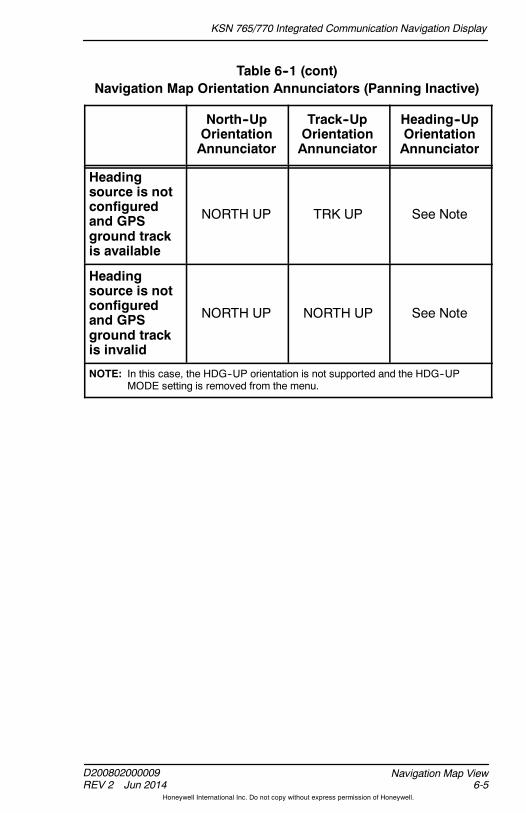
KSN 765/770 Integrated Communication Navigation Display
D200802000009REV 2 Jun 2014 6-5
Navigation Map View
Honeywell International Inc. Do not copy without express permission of Honeywell.
Table 6--1 (cont)Navigation Map Orientation Annunciators (Panning Inactive)
Heading--UpOrientationAnnunciator
Track--UpOrientationAnnunciator
North--UpOrientationAnnunciator
Headingsource is notconfiguredand GPSground trackis available
NORTH UP TRK UP See Note
Headingsource is notconfiguredand GPSground trackis invalid
NORTH UP NORTH UP See Note
NOTE: In this case, the HDG--UP orientation is not supported and the HDG--UPMODE setting is removed from the menu.

KSN 765/770 Integrated Communication Navigation Display
D200802000009REV 2 Jun 2014
Navigation Map View6-6
Honeywell International Inc. Do not copy without express permission of Honeywell.
When panning mode is active, PAN MODE is displayed in theupper--center of the navigation map view and LOCKED is displayedunder the true north orientation indicator symbol, as shown inFigure 6--2.
NOTE: When panning is active and the traffic overlay is selected, thetraffic is removed and the TRFC RMVD annunciation isdisplayed in the lower--left corner.
Figure 6--2PAN MODE Active

KSN 765/770 Integrated Communication Navigation Display
D200802000009REV 2 Jun 2014 6-7
Navigation Map View
Honeywell International Inc. Do not copy without express permission of Honeywell.
Table 6--2 lists the possible orientation displays of the navigation mapview with panning active.
Table 6--2Navigation Map Orientation (Panning Active)
North--UpOrientationDisplayed
Track--UpOrientationDisplayed
Heading--UpOrientationDisplayed
Heading andGPS groundtrackavailable
NORTH UP TRK UP HDG UP
Heading isnot availableor invalid,and GPSground trackis available
NORTH UP TRK UP TRK UP
Headingavailable andGPS groundtrack isunavailable orinvalid
NORTH UP NORTH UP HDG UP
Heading andGPS groundtrack isunavailable orinvalid
NORTH UP NORTH UP NORTH UP
Headingsource is notconfiguredand GPSground trackis available
NORTH UP TRK UP See Note

KSN 765/770 Integrated Communication Navigation Display
D200802000009REV 2 Jun 2014
Navigation Map View6-8
Honeywell International Inc. Do not copy without express permission of Honeywell.
Table 6--2 (cont)Navigation Map Orientation (Panning Active)
Heading--UpOrientationDisplayed
Track--UpOrientationDisplayed
North--UpOrientationDisplayed
Headingsource is notconfiguredand GPSground trackis invalid
NORTH UP North Up See Note
NOTE: In this case, the HDG--UP orientation is not supported and the HDG--UPMODE setting is removed from the menu.
If the internal GPS ground track is not available, the aircraft symbol isremoved from the navigation map view.
Heading and Track Display
In heading--up or track--up mode, the direction of flight value displaysthe heading/track with a resolution of 1 degree and a range of 1 to360 degrees, as shown in Figure 6--3.
NOTE: The direction of flight value is removed from the display whenpanning mode is active.
Figure 6--3Direction of Flight -- Numerical Value

KSN 765/770 Integrated Communication Navigation Display
D200802000009REV 2 Jun 2014 6-9
Navigation Map View
Honeywell International Inc. Do not copy without express permission of Honeywell.
When the track data is available, a cyan dashed line ( ------ ) isdisplayed from the current aircraft symbol to the range ring, as shownin Figure 6--4.
NOTE: The track data line is removed from thedisplay whenpanningmode is active.
Figure 6--4Track Line
If the track data is invalid or unavailable, the track line is not displayed.
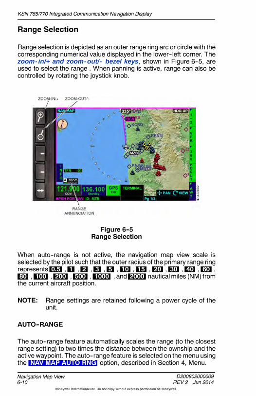
KSN 765/770 Integrated Communication Navigation Display
D200802000009REV 2 Jun 2014
Navigation Map View6-10
Honeywell International Inc. Do not copy without express permission of Honeywell.
Range Selection
Range selection is depicted as an outer range ring arc or circle with thecorresponding numerical value displayed in the lower--left corner. Thezoom- in/+ and zoom- out/- bezel keys, shown in Figure 6--5, areused to select the range . When panning is active, range can also becontrolled by rotating the joystick knob.
Figure 6--5Range Selection
When auto--range is not active, the navigation map view scale isselected by the pilot such that the outer radius of the primary range ringrepresents 0.5 , 1 , 2 , 3 , 5 , 10 , 15 , 20 , 30 , 40 , 60 ,80 , 100 , 200 , 500 , 1000 , and 2000 nauticalmiles (NM) fromthe current aircraft position.
NOTE: Range settings are retained following a power cycle of theunit.
AUTO--RANGE
The auto--range feature automatically scales the range (to the closestrange setting) to two times the distance between the ownship and theactive waypoint. The auto--range feature is selected on the menu usingthe NAV MAP AUTO RNG option, described in Section 4, Menu.
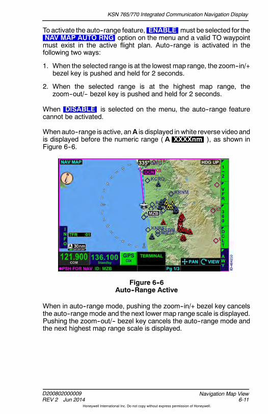
KSN 765/770 Integrated Communication Navigation Display
D200802000009REV 2 Jun 2014 6-11
Navigation Map View
Honeywell International Inc. Do not copy without express permission of Honeywell.
To activate the auto--range feature, ENABLE must be selected for theNAV MAP AUTO RNG option on the menu and a valid TO waypointmust exist in the active flight plan. Auto--range is activated in thefollowing two ways:
1. When the selected range is at the lowest map range, the zoom--in/+bezel key is pushed and held for 2 seconds.
2. When the selected range is at the highest map range, thezoom--out/-- bezel key is pushed and held for 2 seconds.
When DISABLE is selected on the menu, the auto--range featurecannot be activated.
Whenauto--range is active, anA is displayed in white reverse videoandis displayed before the numeric range ( A XXXXnm ), as shown inFigure 6--6.
Figure 6--6Auto--Range Active
When in auto--range mode, pushing the zoom--in/+ bezel key cancelsthe auto--rangemode and the next lower map range scale is displayed.Pushing the zoom--out/-- bezel key cancels the auto--range mode andthe next highest map range scale is displayed.
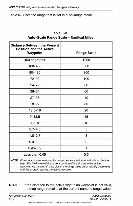
KSN 765/770 Integrated Communication Navigation Display
D200802000009REV 2 Jun 2014
Navigation Map View6-12
Honeywell International Inc. Do not copy without express permission of Honeywell.
Table 6--3 lists the range that is set in auto--range mode.
Table 6--3Auto--Scale Range Scale -- Nautical Miles
Distance Between the PresentPosition and the Active
Waypoint Range Scale
450 or greater 1000
180--450 500
90--180 200
72--90 100
54--72 80
36--54 60
27--36 40
18--27 30
13.5--18 20
9--13.5 15
4.5--9 10
2.7--4.5 5
1.8--2.7 3
0.9--1.8 2
0.45--0.9 1
Less than 0.45 0.5
NOTE: When in auto--range mode, the ranges are selected automatically to give thebest NAV MAP view of the current position of the aircraft to the activewaypoint. As the aircraft gets closer, the range value automatically decreasesuntil the aircraft reaches the active waypoint.
NOTE: If the distance to the active flight plan waypoint is not valid,the map range remains at the current numeric range value.

KSN 765/770 Integrated Communication Navigation Display
D200802000009REV 2 Jun 2014 6-13
Navigation Map View
Honeywell International Inc. Do not copy without express permission of Honeywell.
Navigation Map View Features
When the navigation map view is displayed, the map is capable of, butnot limited to, displaying the following information:
D Navigation aids
D Airports
D Water features
D Boundaries
D Controlled airspace
D Special use airspace
D Obstructions
D Relative terrain
D Miscellaneous annunciators.
The FMS flight plan overlays all other symbols on the navigation mapexcept for the ownship, GPS track, and traffic symbols. The mapdisplays active leg and waypoint in magenta when guidance to thewaypoint is active, greenwhenguidance to thewaypoint is available butnot active, and white if the GPS position fails. All other waypoints andlegs are displayed in white.
AIRPORT SYMBOLS
Airport symbols are positioned on the navigation map view display atthe location corresponding to theairports latitudeand longitude locationobtained from the navigation database.
If the internal SDcard is removed from the card slot, or communicationswith the card fail, the unit will continue to operate using the last data thatwas loaded into memory. As the aircraft position changes, the softwarewill attempt to access the data card to retrieve additional data for a newlocation. When this occurs, if the data card cannot be detected, anannunciation DATABASE FAILURE is displayed. The previouslyloaded data remains available, but new information (such as roads anddetailed terrain data not yet loaded into memory) will not be availableto add to the navigation map.
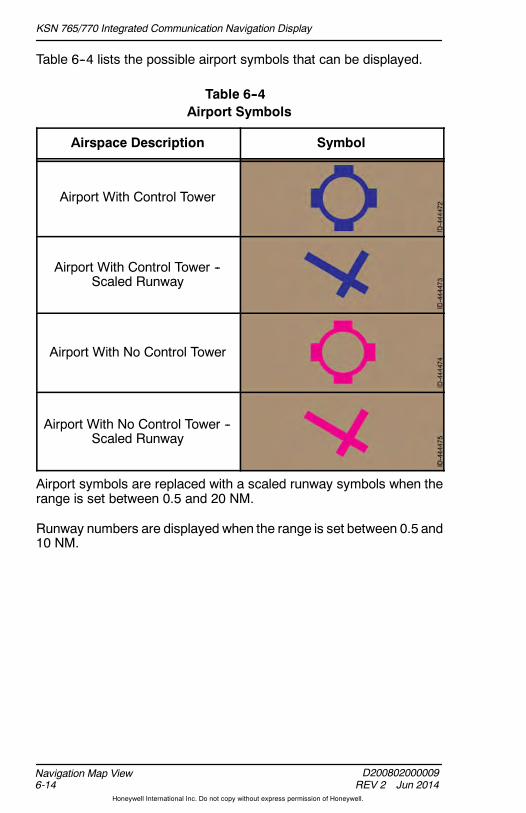
KSN 765/770 Integrated Communication Navigation Display
D200802000009REV 2 Jun 2014
Navigation Map View6-14
Honeywell International Inc. Do not copy without express permission of Honeywell.
Table 6--4 lists the possible airport symbols that can be displayed.
Table 6--4Airport Symbols
Airspace Description Symbol
Airport With Control Tower
Airport With Control Tower --Scaled Runway
Airport With No Control Tower
Airport With No Control Tower --Scaled Runway
Airport symbols are replaced with a scaled runway symbols when therange is set between 0.5 and 20 NM.
Runway numbers are displayed when the range is set between 0.5 and10 NM.
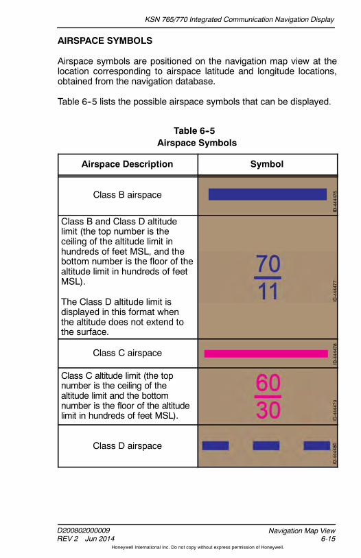
KSN 765/770 Integrated Communication Navigation Display
D200802000009REV 2 Jun 2014 6-15
Navigation Map View
Honeywell International Inc. Do not copy without express permission of Honeywell.
AIRSPACE SYMBOLS
Airspace symbols are positioned on the navigation map view at thelocation corresponding to airspace latitude and longitude locations,obtained from the navigation database.
Table 6--5 lists the possible airspace symbols that can be displayed.
Table 6--5Airspace Symbols
Airspace Description Symbol
Class B airspace
Class B and Class D altitudelimit (the top number is theceiling of the altitude limit inhundreds of feet MSL, and thebottom number is the floor of thealtitude limit in hundreds of feetMSL).
The Class D altitude limit isdisplayed in this format whenthe altitude does not extend tothe surface.
Class C airspace
Class C altitude limit (the topnumber is the ceiling of thealtitude limit and the bottomnumber is the floor of the altitudelimit in hundreds of feet MSL).
Class D airspace
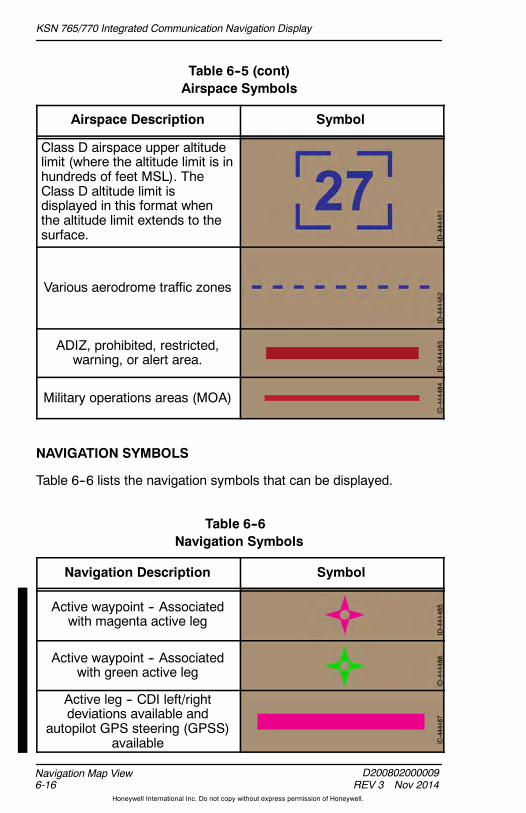
KSN 765/770 Integrated Communication Navigation Display
D200802000009REV 3 Nov 2014
Navigation Map View6-16
Honeywell International Inc. Do not copy without express permission of Honeywell.
Table 6--5 (cont)Airspace Symbols
Airspace Description Symbol
Class D airspace upper altitudelimit (where the altitude limit is inhundreds of feet MSL). TheClass D altitude limit isdisplayed in this format whenthe altitude limit extends to thesurface.
Various aerodrome traffic zones
ADIZ, prohibited, restricted,warning, or alert area.
Military operations areas (MOA)
NAVIGATION SYMBOLS
Table 6--6 lists the navigation symbols that can be displayed.
Table 6--6Navigation Symbols
Navigation Description Symbol
Active waypoint -- Associatedwith magenta active leg
Active waypoint -- Associatedwith green active leg
Active leg -- CDI left/rightdeviations available and
autopilot GPS steering (GPSS)available

KSN 765/770 Integrated Communication Navigation Display
D200802000009REV 3 Nov 2014 6-17
Navigation Map View
Honeywell International Inc. Do not copy without express permission of Honeywell.
Table 6--6 (cont)Navigation Symbols
Navigation Description Symbol
Active leg -- CDI left/rightdeviations available and
autopilot GPSS not available
Other waypoint
Other leg
VOR without a compass rose
VORTAC or VOR/DME withouta compass rose
DME or TACAN without acompass rose
Intersection (INT)
NDB
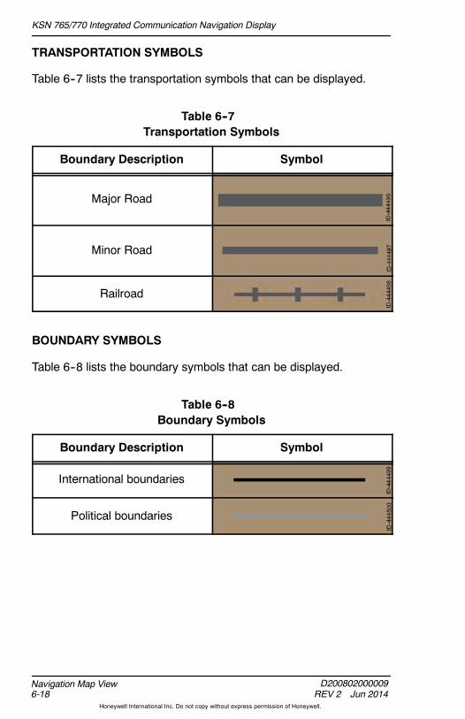
KSN 765/770 Integrated Communication Navigation Display
D200802000009REV 2 Jun 2014
Navigation Map View6-18
Honeywell International Inc. Do not copy without express permission of Honeywell.
TRANSPORTATION SYMBOLS
Table 6--7 lists the transportation symbols that can be displayed.
Table 6--7Transportation Symbols
Boundary Description Symbol
Major Road
Minor Road
Railroad
BOUNDARY SYMBOLS
Table 6--8 lists the boundary symbols that can be displayed.
Table 6--8Boundary Symbols
Boundary Description Symbol
International boundaries
Political boundaries

KSN 765/770 Integrated Communication Navigation Display
D200802000009REV 2 Jun 2014 6-19
Navigation Map View
Honeywell International Inc. Do not copy without express permission of Honeywell.
OBSTRUCTION SYMBOLS
Obstruction symbols are positioned on the navigation map view at thelocation corresponding to the obstructions latitude and longitudelocations, obtained from the navigation database. The possibleobstruction symbols that can be displayed are shown in Figure 6--7.
NOTE: Only reported obstacles are shown.
Figure 6--7Obstruction Symbols
NAV MAP TFR SYMBOLS
When configured to display datalink weather,TFRs are displayed on the NAVMAP view. TFRsare always active for display and cannot be
disabled by the pilot. A TFR status annunciation is displayed in thelower--left corner of the NAV MAP view. TFRs are described in detail inSection 10, Datalink Weather View.
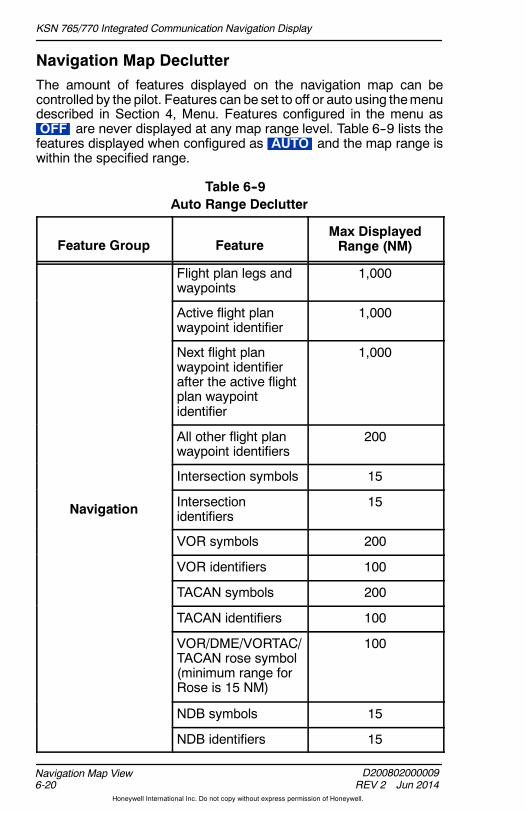
KSN 765/770 Integrated Communication Navigation Display
D200802000009REV 2 Jun 2014
Navigation Map View6-20
Honeywell International Inc. Do not copy without express permission of Honeywell.
Navigation Map DeclutterThe amount of features displayed on the navigation map can becontrolled by the pilot. Features can be set to off or auto using themenudescribed in Section 4, Menu. Features configured in the menu asOFF are never displayed at any map range level. Table 6--9 lists thefeatures displayed when configured as AUTO and the map range iswithin the specified range.
Table 6--9Auto Range Declutter
Feature Group FeatureMax DisplayedRange (NM)
Flight plan legs andwaypoints
1,000
Active flight planwaypoint identifier
1,000
Next flight planwaypoint identifierafter the active flightplan waypointidentifier
1,000
All other flight planwaypoint identifiers
200
Intersection symbols 15
Navigation Intersectionidentifiers
15
VOR symbols 200
VOR identifiers 100
TACAN symbols 200
TACAN identifiers 100
VOR/DME/VORTAC/TACAN rose symbol(minimum range forRose is 15 NM)
100
NDB symbols 15
NDB identifiers 15

KSN 765/770 Integrated Communication Navigation Display
D200802000009REV 2 Jun 2014 6-21
Navigation Map View
Honeywell International Inc. Do not copy without express permission of Honeywell.
Table 6--9 (cont)Auto Range Declutter
Feature GroupMax DisplayedRange (NM)Feature
Large airport symbol 1,000
Large airportidentifier
1,000
Medium/large airportsymbol
500
Medium/large airportidentifier
100
AirportsMedium airportsymbol
200
Medium airportidentifier
80
Medium/small airportsymbol
100
Medium small airportidentifier
60
Small airport symbol 60
Small airportidentifier
40
Water Oceans/seas 1 1,000
Rivers/lakes 1 1,000
Transportation Roads and railroads 20
Boundaries International 1,000
State or province 1,000

KSN 765/770 Integrated Communication Navigation Display
D200802000009REV 2 Jun 2014
Navigation Map View6-22
Honeywell International Inc. Do not copy without express permission of Honeywell.
Table 6--9 (cont)Auto Range Declutter
Feature GroupMax DisplayedRange (NM)Feature
Airways Low legs (Victor) 1 200
High legs (Jet) 1 200
(Airways selected fordisplay using a bezelsoftkey.)
Airway designatorandoutbound/inboundradials 1
200
Terrain(Relative terrain andobstructions are
Relative terrain 1, 2 Limited to 100, butdisplayed to 1,000.
obstructions areselected for displayusing a bezelsoftkey.)
Obstructions 1 Limited to 40, butdisplayed to 1,000.
Class A, B, and Cwithout sectors
200
Class A, B, C, D,and F with sectors
60
ControlledAirspace
Class G 60Airspace
Various aerodrometraffic zones
60
Class B, C, and Daltitude limits
40

KSN 765/770 Integrated Communication Navigation Display
D200802000009REV 2 Jun 2014 6-23
Navigation Map View
Honeywell International Inc. Do not copy without express permission of Honeywell.
Table 6--9 (cont)Auto Range Declutter
Feature GroupMax DisplayedRange (NM)Feature
Prohibited 200
Prohibited number 40
TFRs 1, 2, 3 1,000
Restricted, Warning,Training, and Danger
200
Restricted andWarning number
40
Special UseAi
MOA, Alert 200pAirspace
MOA and Alertnumber
40
Special flight rulesarea
200
Special flight rulesarea identifier
40
ADIZ 500
ADIZ identifiers 40
1 -- These map features are not configurable with the menu.2 -- Always on regardless of declutter settings.3 -- The TFR annunciation is always displayed directly above the
range setting.
NOTE: Display settings are retained following a power cycle of theunit.

KSN 765/770 Integrated Communication Navigation Display
D200802000009REV 2 Jun 2014
Navigation Map View6-24
Honeywell International Inc. Do not copy without express permission of Honeywell.
The navigation map can also be decluttered using the DCLT bezelsoftkey. Each push of the DCLT bezel softkey changes the declutterlevel in the following order:
High Medium/High Medium/Low Low Off Repeat
In general, the higher the declutter level, the more features displayedon the navigation map. The selected declutter level is displayed usinga declutter icon in the lower--left corner of the navigation map display.Figure 6--8 shows five declutter levels.
Figure 6--8Declutter Icons
Table 6--10 lists the features displayed on the navigation map for eachdeclutter level.
Table 6--10Declutter Levels
Feature HighMed/High
Med/Low Low Off
MFD Function FlightPlan Legs andWaypoints
x x x x

KSN 765/770 Integrated Communication Navigation Display
D200802000009REV 2 Jun 2014 6-25
Navigation Map View
Honeywell International Inc. Do not copy without express permission of Honeywell.
Table 6--10 (cont)Declutter Levels
Feature OffLowMed/Low
Med/HighHigh
FMS Function FlightPlan Legs andWaypoints (NotConfigurable WithThe Menu
x x x x x
Intersections x
VORs x
NDBs x
Hard SurfacedAirports
x x x x
Other ThanNon--Hard SurfacedAirports
x x x x
Oceans/Seas x x x x x
Rivers/Lakes x x x x x
Roads and Railroads x
InternationalBoundaries/ADIZ
x x
Province or StateBoundaries
x
Controlled Airspace x x x
TFR and ProhibitedAirspace
x x x x x
Special Use Airspace(Not Including TFRsand ProhibitedAirspace)
x x

KSN 765/770 Integrated Communication Navigation Display
D200802000009REV 2 Jun 2014
Navigation Map View6-26
Honeywell International Inc. Do not copy without express permission of Honeywell.
NAVIGATION MAP VIEW STYLES
The pilot can choose to display the navigation map in a 360--degree orarc view as well as a VFR or IFR map. The selected setting is retainedfollowing a power cycle of the unit.
360--Degree Or Arc View
The pilot can toggle between arc and 360 views by pushing the ARCand 360 bezel softkeys. When in arc view, the ARC bezel softkeylabel is displayed and the ownship symbol is located near the bottomof the view, as shown in Figure 6--9.
Figure 6--9ARC Mode

KSN 765/770 Integrated Communication Navigation Display
D200802000009REV 2 Jun 2014 6-27
Navigation Map View
Honeywell International Inc. Do not copy without express permission of Honeywell.
When in 360--degree view, the 360 bezel softkey label is displayedand the ownship symbol is located in the center of the view, as shownin Figure 6--10.
Figure 6--10360--Degree Mode
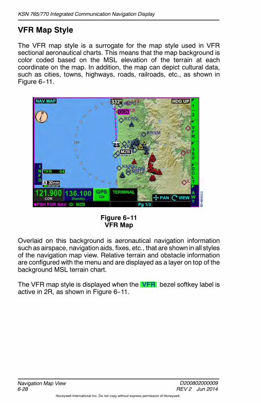
KSN 765/770 Integrated Communication Navigation Display
D200802000009REV 2 Jun 2014
Navigation Map View6-28
Honeywell International Inc. Do not copy without express permission of Honeywell.
VFR Map Style
The VFR map style is a surrogate for the map style used in VFRsectional aeronautical charts. This means that the map background iscolor coded based on the MSL elevation of the terrain at eachcoordinate on the map. In addition, the map can depict cultural data,such as cities, towns, highways, roads, railroads, etc., as shown inFigure 6--11.
Figure 6--11VFR Map
Overlaid on this background is aeronautical navigation informationsuchas airspace, navigation aids, fixes, etc., that are shown in all stylesof the navigation map view. Relative terrain and obstacle informationare configured with the menu and are displayed as a layer on top of thebackground MSL terrain chart.
The VFR map style is displayed when the VFR bezel softkey label isactive in 2R, as shown in Figure 6--11.
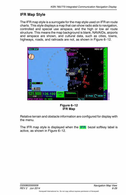
KSN 765/770 Integrated Communication Navigation Display
D200802000009REV 2 Jun 2014 6-29
Navigation Map View
Honeywell International Inc. Do not copy without express permission of Honeywell.
IFR Map Style
The IFRmap style is a surrogate for themap style used on IFR en routecharts. This style displays amap that can show radio aids to navigation,controlled and special use airspace, and the high or low air routestructure. This means the map background is blank, NAVAIDs, airportsand airspace are shown, and cultural data, such as cities, towns,highways, roads, and railroads are not, as shown in Figure 6--12.
Figure 6--12IFR Map
Relative terrain and obstacle information are configured for displaywiththe menu.
The IFR map style is displayed when the IFR bezel softkey label isactive, as shown in Figure 6--12.
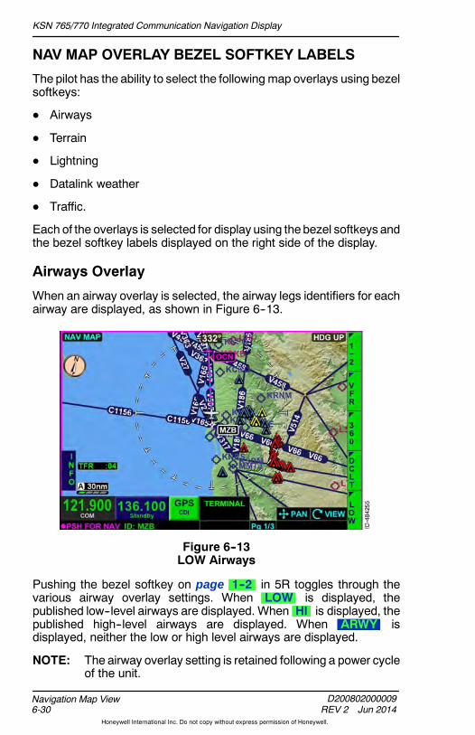
KSN 765/770 Integrated Communication Navigation Display
D200802000009REV 2 Jun 2014
Navigation Map View6-30
Honeywell International Inc. Do not copy without express permission of Honeywell.
NAV MAP OVERLAY BEZEL SOFTKEY LABELS
The pilot has the ability to select the following map overlays using bezelsoftkeys:
D Airways
D Terrain
D Lightning
D Datalink weather
D Traffic.
Each of the overlays is selected for display using thebezel softkeys andthe bezel softkey labels displayed on the right side of the display.
Airways Overlay
When an airway overlay is selected, the airway legs identifiers for eachairway are displayed, as shown in Figure 6--13.
Figure 6--13LOW Airways
Pushing the bezel softkey on page 1--2 in 5R toggles through thevarious airway overlay settings. When LOW is displayed, thepublished low--level airways are displayed. When HI is displayed, thepublished high--level airways are displayed. When ARWY isdisplayed, neither the low or high level airways are displayed.
NOTE: The airway overlay setting is retained following a power cycleof the unit.

KSN 765/770 Integrated Communication Navigation Display
D200802000009REV 2 Jun 2014 6-31
Navigation Map View
Honeywell International Inc. Do not copy without express permission of Honeywell.
Terrain Overlay
The terrain overlay permits terrain data to overlay on the navigationmap display. The terrain overlay is controlled using the TERR bezelsoftkey on page 2--2 displayed in 2R shown in Figure 6--14.
Figure 6--14Terrain Overlay
The terrain overlay is active when the TERR bezel softkey label isdisplayed and inactive when the TERR bezel softkey label isdisplayed.
NOTE: When the terrain overlay is inactive, only obstructions within500 feet are displayed.
The terrain overlay and NEXRAD overlay are mutually exclusive. Onlyone can be displayed at a time on the navigation map. The TERRbezel softkey label is inactive when the NXRD bezel softkey ispushed.
When corrected barometric altitude is configured and valid, theBARO TERR annunciation is displayed in the lower--left corner of thedisplay, as shown in Figure 6--14. When barometric altitude is notconfigured or invalid and geometric altitude is valid, GPS TERR isdisplayed in the lower--left corner of the display.
If the corrected barometric altitude,geometric altitude, aircraft position, orheading and GPS track are invalid, awhite TERR annunciator is displayed
with a red ( -- ) line through the annunciator and the obstructioncoloring is removed from the display.

KSN 765/770 Integrated Communication Navigation Display
D200802000009REV 2 Jun 2014
Navigation Map View6-32
Honeywell International Inc. Do not copy without express permission of Honeywell.
If terrain and obstruction data is invalid or unavailable, cyan is shownin place of the invalid or unavailable terrain.
NOTE: An expired database does not display the basemap featureas invalid.
Terrain color for the overlay view is described in detail in Section 8,Terrain View.
Lightning Overlay
The lightning overlay permits datalink satellite lightning information orWX--500 Stormscope data to overlay on the navigation map display.The lightning overlay is controlled using thebezel softkey on page 2--2displayed in 3R, shown in Figure 6--15.
Figure 6--15Lightning Overlay
The lightning overlay bezel softkey label is a four--position label thatcontrols the lightning overlay. The following is a description of the fourpossible positions of the bezel softkey label.
D LTNG -- Lightning overlay is off.
D LTNG -- Datalink weather lightning overlay is active.
D STRK -- WX--500 Stormscope strike mode symbols ( X )overlay is active.
D CELL -- WX--500 Stormscope cell mode symbols ( + ) overlayis active.
NOTE: The lightning overlay setting is retained after a power cycleof the unit.

KSN 765/770 Integrated Communication Navigation Display
D200802000009REV 2 Jun 2014 6-33
Navigation Map View
Honeywell International Inc. Do not copy without express permission of Honeywell.
WhenWX--500Stormscope overlay is active onthe navigation map view, the lightning, strike, orcell rate annunciator is displayed in the lower--left
of the display. The WX--500 Stormscope does not require a validheading to display on the NAVMAP overlay. A valid heading is requiredonly for the strikes view.
If the GPS position is invalid or unavailable, thelightning symbols are removed from the display,and a red horizontal line is displayed over therate annunciator.
Satellite lightning is described in Section 10, Datalink Weather View.Lightning is described in detail in Section 12, Lightning Detection View.
Lightning symbols are removed from thenavigation map and xRMVD or +RMVDreplaces the rate annunciator in the lower--right
corner when the range is less than 20 NM. Lightning data is notdisplayed if aircraft heading information is not available.

KSN 765/770 Integrated Communication Navigation Display
D200802000009REV 2 Jun 2014
Navigation Map View6-34
Honeywell International Inc. Do not copy without express permission of Honeywell.
Datalink Weather Overlay
The datalink weather overlay enables display of NEXRAD andprecipitation on the navigation map, as shown in Figure 6--16.Coverage is limited to the US, Puerto Rico, and Canada. The datalinkweather overlay is active when the NXRD bezel softkey label isdisplayed and inactive when the NXRD bezel softkey label isdisplayed. The datalink weather overlay default setting is inactive( NXRD ).
Figure 6--16Datalink Weather Overlay
The NEXRAD overlay and terrain overlay are mutually exclusive. Onlyone can be displayed at a time on the navigation map. The NXRDbezel softkey label becomes inactive when the TERR bezel softkeyis pushed.
The XM product ages box is displayed in thelower--left corner of the navigation map anddatalink weather pages. The XM product agesfor the selected weather products are displayed(inminutes) in greenwhen data is being receivedand updated.
If the generated data age is not available or afterstartup no valid data has been received from thereceiver, the XM data ages are displayed asdashes.
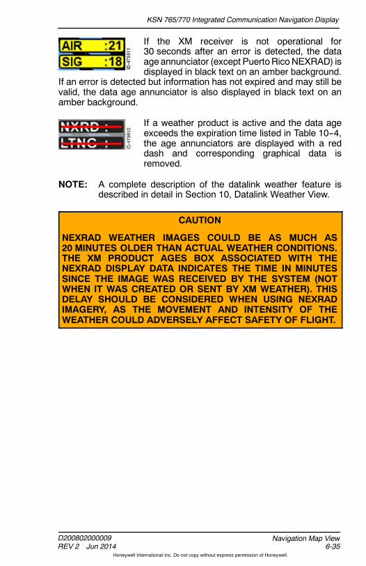
KSN 765/770 Integrated Communication Navigation Display
D200802000009REV 2 Jun 2014 6-35
Navigation Map View
Honeywell International Inc. Do not copy without express permission of Honeywell.
If the XM receiver is not operational for30 seconds after an error is detected, the dataageannunciator (except PuertoRicoNEXRAD) isdisplayed in black text on an amber background.
If an error is detected but information has not expired and may still bevalid, the data age annunciator is also displayed in black text on anamber background.
If a weather product is active and the data ageexceeds the expiration time listed in Table 10--4,the age annunciators are displayed with a reddash and corresponding graphical data isremoved.
NOTE: A complete description of the datalink weather feature isdescribed in detail in Section 10, Datalink Weather View.
CAUTION
NEXRAD WEATHER IMAGES COULD BE AS MUCH AS20 MINUTES OLDER THAN ACTUAL WEATHER CONDITIONS.THE XM PRODUCT AGES BOX ASSOCIATED WITH THENEXRAD DISPLAY DATA INDICATES THE TIME IN MINUTESSINCE THE IMAGE WAS RECEIVED BY THE SYSTEM (NOTWHEN IT WAS CREATED OR SENT BY XM WEATHER). THISDELAY SHOULD BE CONSIDERED WHEN USING NEXRADIMAGERY, AS THE MOVEMENT AND INTENSITY OF THEWEATHER COULD ADVERSELY AFFECT SAFETY OF FLIGHT.

KSN 765/770 Integrated Communication Navigation Display
D200802000009REV 2 Jun 2014
Navigation Map View6-36
Honeywell International Inc. Do not copy without express permission of Honeywell.
Traffic Overlay
The traffic overlay permits traffic information to overlay on thenavigation map display. The traffic overlay is controlled using the bezelsoftkey on page 2--2 displayed in 5R, shown in Figure 6--17.
Figure 6--17Traffic Overlay
The traffic overlay bezel softkey label in 5R is a five--position label thatcontrols the traffic overlay. The following is a description of the fivepossible positions of the label.
D TRFC -- The traffic overlay is off.
D TFCN -- Displays the traffic overlay in the normal traffic setting.Traffic is displayed within 2,700 feet above and below the currentaircraft.
D TFCU -- Displays the traffic overlay in the unrestricted trafficsetting. Traffic is displayed within 9,900 feet above and below thecurrent aircraft.
D TFCA -- Displays the traffic overlay in the above traffic setting.Traffic is displayed within 2,700 feet below the current aircraft, to9,900 feet above the current aircraft.
D TFCB -- Displays the traffic overlay in the below traffic setting.Traffic is displayed within 2,700 feet above the current aircraft, to9,900 feet below the current aircraft.

KSN 765/770 Integrated Communication Navigation Display
D200802000009REV 2 Jun 2014 6-37
Navigation Map View
Honeywell International Inc. Do not copy without express permission of Honeywell.
WARNING
THEPILOTMUSTNOTUSETHETRAFFICDISPLAYTO INITIATEEVASIVE MANEUVERING. ATC PROCEDURES AND VISUALACQUISITION OF THE INTRUDER PRIOR TO INITIATION OFEVASIVEMANEUVERSMUST CONTINUE TO BE THE PRIMARYMEANS OF ENSURING AIRCRAFT SEPARATION. THE SYSTEMLACKS THE RESOLUTION (THE ACCURACY) NECESSARYFOR EVASIVE MANEUVERING.
When a TAS TCAS sensor is installed and trafficinformation is in a failure status, the TRFCannunciation is displayed in white text with a redline through. When a TAS TCAS sensor isinstalled and valid traffic information is being
received, the TRFC annunciation is displayed. When a TIS TCASsensor is installed and traffic information is unavailable or out of range,the TRFC UNAV annunciation is displayed.
When panning is active, and the traffic overlay is on, the traffic overlayis removed from the display and the amber TRFC RMVD annunciatoris displayed. When panning is exited, the traffic overlay is againdisplayed.
When the traffic overlay is active with the navigation map view orientednorth--up (in split or thumbnail view), and a traffic view is selected inanotherwindow, the traffic overlay is removed from thenavigationmapto avoid confusion and the amber TRFC RMVD annunciator isdisplayed.
Traffic is described in detail in Section 9, Traffic View.
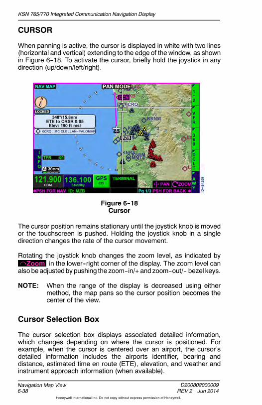
KSN 765/770 Integrated Communication Navigation Display
D200802000009REV 2 Jun 2014
Navigation Map View6-38
Honeywell International Inc. Do not copy without express permission of Honeywell.
CURSOR
When panning is active, the cursor is displayed in white with two lines(horizontal and vertical) extending to the edge of thewindow, as shownin Figure 6--18. To activate the cursor, briefly hold the joystick in anydirection (up/down/left/right).
Figure 6--18Cursor
The cursor position remains stationary until the joystick knob is movedor the touchscreen is pushed. Holding the joystick knob in a singledirection changes the rate of the cursor movement.
Rotating the joystick knob changes the zoom level, as indicated byZoom in the lower--right corner of the display. The zoom level canalsobeadjustedby pushing the zoom--in/+ and zoom--out/-- bezel keys.
NOTE: When the range of the display is decreased using eithermethod, the map pans so the cursor position becomes thecenter of the view.
Cursor Selection Box
The cursor selection box displays associated detailed information,which changes depending on where the cursor is positioned. Forexample, when the cursor is centered over an airport, the cursor’sdetailed information includes the airports identifier, bearing anddistance, estimated time en route (ETE), elevation, and weather andinstrument approach information (when available).

KSN 765/770 Integrated Communication Navigation Display
D200802000009REV 2 Jun 2014 6-39
Navigation Map View
Honeywell International Inc. Do not copy without express permission of Honeywell.
The cursor can also be positioned over non--object navigation mapfeatures such as terrain, rivers, and highways. When the cursor ismoved over a non--object, the non--object cursor box is displayed, asshown in Figure 6--19.
Figure 6--19Non--Object Cursor Box
The information displayed in the non--object cursor box is as follows:
D Bearing and distance from the current aircraft symbol to the cursor
D Estimated time en route from the current aircraft symbol to thecursor using current groundspeed
D Terrain elevation at the cursor.
When the pilot moves the cursor over an object, the object cursor boxis displayed directly below the non--object cursor box, as shown inFigure 6--20.
Figure 6--20Object Cursor Box
When either the right window of the thumbnail layout or the full screenlayout is in use, and the cursor is over multiple objects, no more thanfive object cursor boxes are displayed.
When the right or left window of the split screen layout is in use, and thecursor is over multiple objects, no more than three object cursor boxesare displayed.

KSN 765/770 Integrated Communication Navigation Display
D200802000009REV 2 Jun 2014
Navigation Map View6-40
Honeywell International Inc. Do not copy without express permission of Honeywell.
Table 6--11 lists the priority of the objects that are displayed in theobjectcursor box when the cursor is over multiple objects.
Table 6--11Object Cursor Box Priority
Object Priority
Obstacle 1
Airport 2
VOR 3
NDB 4
Intersection 5
Airspaces 6(See Note)
NOTE: Airspaces are prioritized by size (small to large). When the size of theairspace is identical, then the airspace is prioritized by class.
If the internal GPS is not available, the cursor selection box displaysdashes ( ------ ). When the estimated time en route (ETE) is greaterthan 9 hours, 59 minutes (9:59), the cursor selection box displaysdashes ( --:---- ).
Table 6--12 lists the information displayed in the object cursor boxes.
Table 6--12Object Cursor Box Information
Object Information
Obstacle Obstacle elevation at the cursor
Airport Symbol, identifier, and name
VOR Symbol, identifier, and name
NDB Symbol, identifier, and name
Intersection Symbol and name
Various aerodrome traffic zones Name of airspace
Class D Name of airspace followed byClass D

KSN 765/770 Integrated Communication Navigation Display
D200802000009REV 2 Jun 2014 6-41
Navigation Map View
Honeywell International Inc. Do not copy without express permission of Honeywell.
Table 6--12 (cont)Object Cursor Box Information
Object Information
Class C Name of airspace followed byClass C
Class B Name of airspace followed byClass B
Special use airspace Name of special use airspace,followed by type (i.e., TFRs,advisory, ADIZ, MOA, restricted,TSA, etc.)
When controlled airspace is under the cursor, the airspace border andaltitude limit for the controlled airspace is highlighted, as shown inFigure 6--21. When special use airspace is under the cursor, theairspace border and airspace name are highlighted.
Figure 6--21Airspace Highlighted
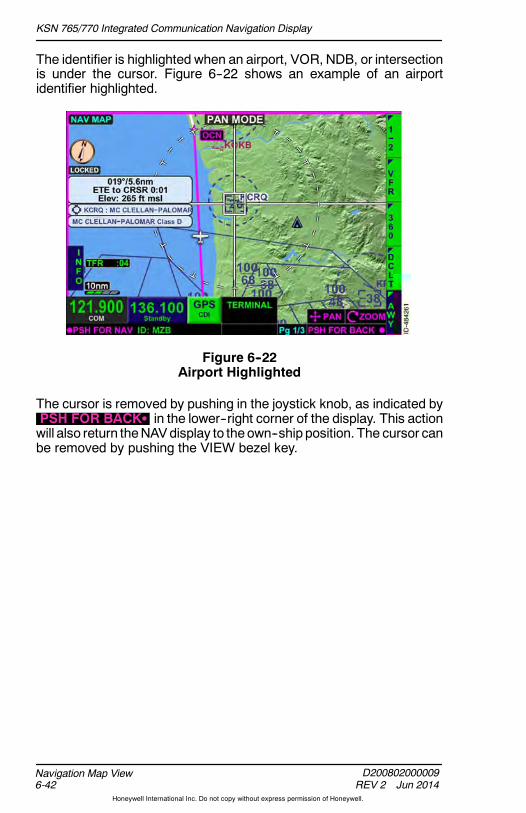
KSN 765/770 Integrated Communication Navigation Display
D200802000009REV 2 Jun 2014
Navigation Map View6-42
Honeywell International Inc. Do not copy without express permission of Honeywell.
The identifier is highlighted when an airport, VOR, NDB, or intersectionis under the cursor. Figure 6--22 shows an example of an airportidentifier highlighted.
Figure 6--22Airport Highlighted
The cursor is removed by pushing in the joystick knob, as indicated byPSH FOR BACKS in the lower--right corner of the display. This actionwill also return theNAVdisplay to theown--ship position. The cursor canbe removed by pushing the VIEW bezel key.

KSN 765/770 Integrated Communication Navigation Display
D200802000009REV 2 Jun 2014 6-43
Navigation Map View
Honeywell International Inc. Do not copy without express permission of Honeywell.
NAVIGATION MAP INFO VIEW
The navigation map can provide detailed information about airports,VORs, intersections, airspace, and TFRs shown on the display. Thenavigation map info view is activated by pushing the INFO bezelsoftkey, shown in Figure 6--23.
NOTE: The INFO bezel softkey label is also displayed in the FMSview when either the waypoint list or navigation map windowis selected.
Figure 6--23Navigation Map Info Key
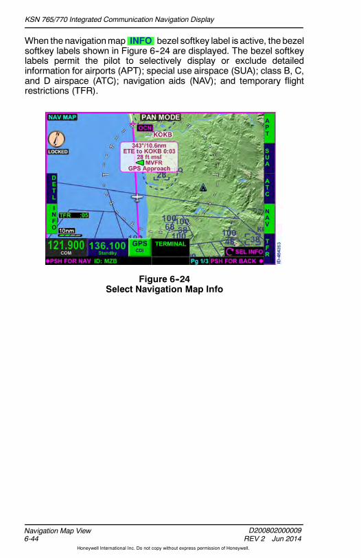
KSN 765/770 Integrated Communication Navigation Display
D200802000009REV 2 Jun 2014
Navigation Map View6-44
Honeywell International Inc. Do not copy without express permission of Honeywell.
When the navigationmap INFO bezel softkey label is active, thebezelsoftkey labels shown in Figure 6--24 are displayed. The bezel softkeylabels permit the pilot to selectively display or exclude detailedinformation for airports (APT); special use airspace (SUA); class B, C,and D airspace (ATC); navigation aids (NAV); and temporary flightrestrictions (TFR).
Figure 6--24Select Navigation Map Info

KSN 765/770 Integrated Communication Navigation Display
D200802000009REV 2 Jun 2014 6-45
Navigation Map View
Honeywell International Inc. Do not copy without express permission of Honeywell.
Once the bezel softkey label selections are made, rotating the joystickknob toggles through detailed information for the active bezel softkeylabels within the navigation map display area. A navigation map item isindicated as active with blue reverse text and inactive with greenreverse text. Table 6--13 lists theNAVmap info bezel softkey labels andthe associated graphical symbols.
Table 6--13NAV Map Info Bezel Softkey Labels
NAV Map Info Bezel SoftkeyLabels Graphical Symbols
APT Airport Symbols
SUA Prohibited AreasRestricted AreasAlert AreasWarning AreasMilitary Operations AreasADIZ
ATC Class B sectorsClass C sectorsClass D sectorsVarious Aerodrome TrafficZones
NAV VOR SymbolsNDB SymbolsIntersection Symbols
TFR Temporary Flight Restrictions
NOTE: The NAVmap info bezel softkey label selections are retainedfollowing a power cycle of the unit.
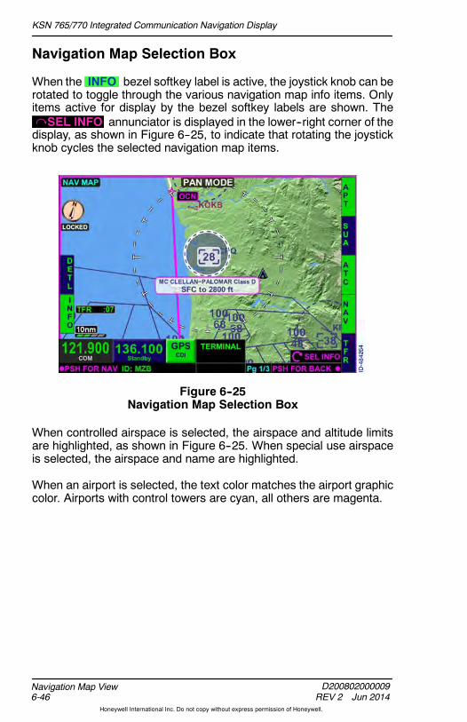
KSN 765/770 Integrated Communication Navigation Display
D200802000009REV 2 Jun 2014
Navigation Map View6-46
Honeywell International Inc. Do not copy without express permission of Honeywell.
Navigation Map Selection Box
When the INFO bezel softkey label is active, the joystick knob can berotated to toggle through the various navigation map info items. Onlyitems active for display by the bezel softkey labels are shown. TheSEL INFO annunciator is displayed in the lower--right corner of thedisplay, as shown in Figure 6--25, to indicate that rotating the joystickknob cycles the selected navigation map items.
Figure 6--25Navigation Map Selection Box
When controlled airspace is selected, the airspace and altitude limitsare highlighted, as shown in Figure 6--25. When special use airspaceis selected, the airspace and name are highlighted.
When an airport is selected, the text color matches the airport graphiccolor. Airports with control towers are cyan, all others are magenta.

KSN 765/770 Integrated Communication Navigation Display
D200802000009REV 2 Jun 2014 6-47
Navigation Map View
Honeywell International Inc. Do not copy without express permission of Honeywell.
When the range is set to a low setting, there may not be any itemsselectable to display. When there are no objects displayed within theselectable view, the message No selectable items within view isdisplayed, as shown in Figure 6--26. Changing the range to a largerscale usually displays objects into the view. Panning to an area that hasobjects using the same range may also display objects.
Figure 6--26No Selectable Items Within View
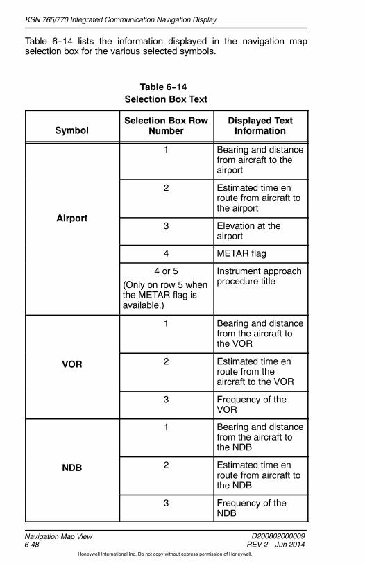
KSN 765/770 Integrated Communication Navigation Display
D200802000009REV 2 Jun 2014
Navigation Map View6-48
Honeywell International Inc. Do not copy without express permission of Honeywell.
Table 6--14 lists the information displayed in the navigation mapselection box for the various selected symbols.
Table 6--14Selection Box Text
SymbolSelection Box Row
NumberDisplayed TextInformation
1 Bearing and distancefrom aircraft to theairport
Airport
2 Estimated time enroute from aircraft tothe airport
Airport3 Elevation at the
airport
4 METAR flag
4 or 5(Only on row 5 whenthe METAR flag isavailable.)
Instrument approachprocedure title
1 Bearing and distancefrom the aircraft tothe VOR
VOR 2 Estimated time enroute from theaircraft to the VOR
3 Frequency of theVOR
1 Bearing and distancefrom the aircraft tothe NDB
NDB 2 Estimated time enroute from aircraft tothe NDB
3 Frequency of theNDB
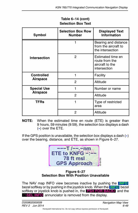
KSN 765/770 Integrated Communication Navigation Display
D200802000009REV 2 Jun 2014 6-49
Navigation Map View
Honeywell International Inc. Do not copy without express permission of Honeywell.
Table 6--14 (cont)Selection Box Text
SymbolDisplayed TextInformation
Selection Box RowNumber
1 Bearing and distancefrom the aircraft tothe intersection
Intersection 2 Estimated time enroute from theaircraft to theintersection
ControlledAirspace
1 FacilityAirspace
2 Altitude
Special UseAirspace
1 Number or nameAirspace
2 Altitude
TFRs 1 Type of restrictedarea
2 Altitude
NOTE: When the estimated time en route (ETE) is greater than9 hours, 59 minutes (9:59), the selection box displays a dash(--) over the ETE.
If the GPS position is unavailable, the selection box displays a dash (--)over the bearing, distance, and ETE, as shown in Figure 6--27.
Figure 6--27Selection Box With Position Unavailable
The NAV map INFO view becomes inactive by pushing the INFObezel softkey or by pushing in the joystick knob.When the INFO bezelsoftkey or joystick knob is pushed in, the PSH FOR BACKS and theSEL INFO annunciator is removed from the display.

KSN 765/770 Integrated Communication Navigation Display
D200802000009REV 2 Jun 2014
Navigation Map View6-50
Honeywell International Inc. Do not copy without express permission of Honeywell.
Navigation Map Detail Control
When the INFO bezel softkey label is active, the DETL bezel softkeylabel is displayed on the left--side of the display. Pushing the DETLbezel softkey displays a detail information box based on the itemselected on the navigation map display, as shown in Figure 6--28.
NOTE: The DETL bezel softkey label is not displayed whenselectable items are not within view.
Figure 6--28Navigation Map Detail
The detail bezel softkey labels displayed along the right side of thedisplay vary depending on the item selected on the navigation map.Figure 6--28 shows an example of a detail information box of KOKBandthe associated bezel softkey labels.

KSN 765/770 Integrated Communication Navigation Display
D200802000009REV 2 Jun 2014 6-51
Navigation Map View
Honeywell International Inc. Do not copy without express permission of Honeywell.
Table 6--15 lists the selectable navigationmap itemsand theassociatedNAV map detail bezel softkey labels displayed.
Table 6--15NAV Map Detail Control Bezel Softkey Labels
Graphical Symbol Bezel Softkey Labels
Airport
APTCOMRWYWX
(Displayed when XM WX isconfigured.)
CHRT(Displayed when the selectedairport has an associatedterminal procedure.)
VOR VOR
Intersection INT
NDB NDB
TFR TFR
Special Use Airspace SUA
Controlled Airspace ATC
NOTE: Only one NAV map detail control bezel softkey label can beactive at a time.
Pushing in the joystick knob or pushing the DETL bezel softkeydeactivates the NAV map detail control mode and returns to the NAVmap INFO view.

KSN 765/770 Integrated Communication Navigation Display
D200802000009REV 2 Jun 2014
Navigation Map View6-52
Honeywell International Inc. Do not copy without express permission of Honeywell.
Table 6--16 lists the information displayed in the detail information box.
Table 6--16Detailed Box Text
SymbolDetailed BezelSoftkey Label
Information Displayed (ifavailable)
Airport
APT
Airport identifierName of airportLocation (city, state, andcountry)Elevation of airportBearing TO and FROMairportDistance to airportEstimated time en route(ETE) to airportLatitude and longitude atairport
COM Frequencies and call signs
RWY Airport identifierName of airportRunwayRunway lengths and widthsRunway surface typeType of runway lightingRunway approach andfrequency; includes pushbutton (KSN 770 only) whichwill populate NAV standbyfrequency when pushed
WX METAR and TAF textinformation
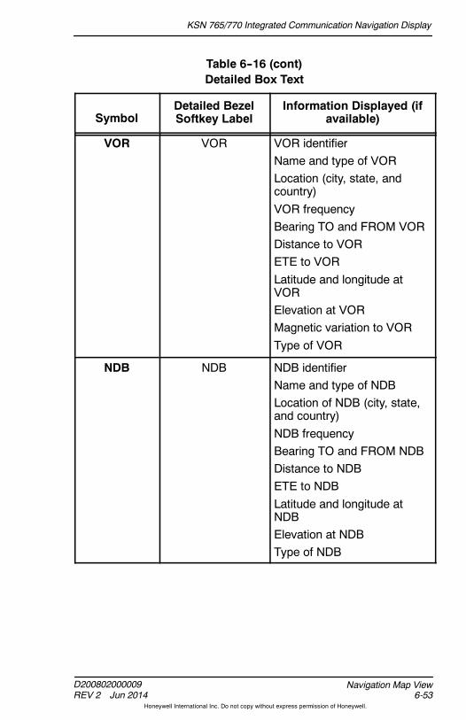
KSN 765/770 Integrated Communication Navigation Display
D200802000009REV 2 Jun 2014 6-53
Navigation Map View
Honeywell International Inc. Do not copy without express permission of Honeywell.
Table 6--16 (cont)Detailed Box Text
SymbolInformation Displayed (if
available)Detailed BezelSoftkey Label
VOR VOR VOR identifierName and type of VORLocation (city, state, andcountry)VOR frequencyBearing TO and FROM VORDistance to VORETE to VORLatitude and longitude atVORElevation at VORMagnetic variation to VORType of VOR
NDB NDB NDB identifierName and type of NDBLocation of NDB (city, state,and country)NDB frequencyBearing TO and FROM NDBDistance to NDBETE to NDBLatitude and longitude atNDBElevation at NDBType of NDB

KSN 765/770 Integrated Communication Navigation Display
D200802000009REV 2 Jun 2014
Navigation Map View6-54
Honeywell International Inc. Do not copy without express permission of Honeywell.
Table 6--16 (cont)Detailed Box Text
SymbolInformation Displayed (if
available)Detailed BezelSoftkey Label
Intersection INT Intersection identifierName of intersectionBearing TO and FROMintersectionDistance to intersectionETE to intersectionLatitude and longitude atintersectionType of reporting point(compulsory ornon--compulsory)
ControlledAirspace
ATC FacilityAltitudeLow/High separation altitudeApproach control and unicomfrequencies
Special UseAirspace
SUA Number or nameType of special use airspaceAltitudeLow/High separation altitudeControlling agencyContact facility
TFR TFR Type of restricted areaNameAffected altitudeData and time the TFR wascreated and modifiedData and time the TFR isactive and expires
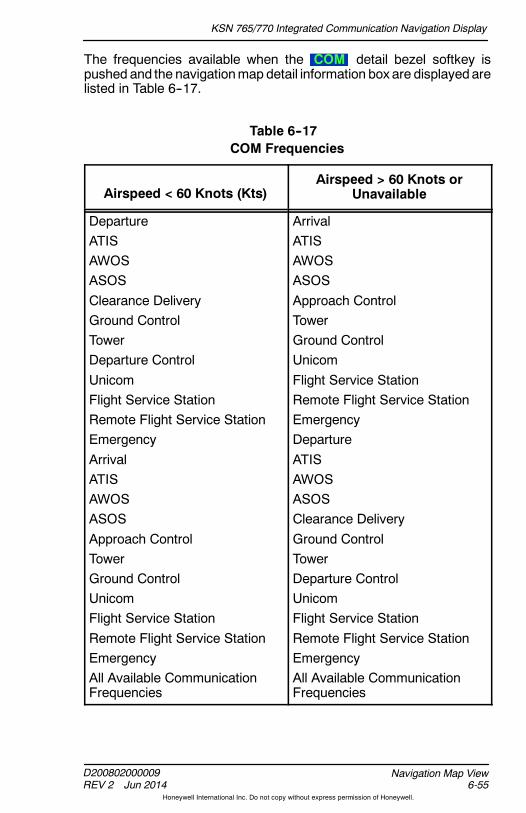
KSN 765/770 Integrated Communication Navigation Display
D200802000009REV 2 Jun 2014 6-55
Navigation Map View
Honeywell International Inc. Do not copy without express permission of Honeywell.
The frequencies available when the COM detail bezel softkey ispushed and the navigationmap detail information box are displayedarelisted in Table 6--17.
Table 6--17COM Frequencies
Airspeed < 60 Knots (Kts)Airspeed > 60 Knots or
Unavailable
DepartureATISAWOSASOSClearance DeliveryGround ControlTowerDeparture ControlUnicomFlight Service StationRemote Flight Service StationEmergencyArrivalATISAWOSASOSApproach ControlTowerGround ControlUnicomFlight Service StationRemote Flight Service StationEmergencyAll Available CommunicationFrequencies
ArrivalATISAWOSASOSApproach ControlTowerGround ControlUnicomFlight Service StationRemote Flight Service StationEmergencyDepartureATISAWOSASOSClearance DeliveryGround ControlTowerDeparture ControlUnicomFlight Service StationRemote Flight Service StationEmergencyAll Available CommunicationFrequencies
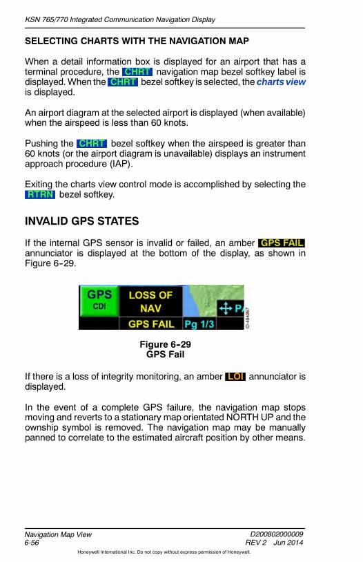
KSN 765/770 Integrated Communication Navigation Display
D200802000009REV 2 Jun 2014
Navigation Map View6-56
Honeywell International Inc. Do not copy without express permission of Honeywell.
SELECTING CHARTS WITH THE NAVIGATION MAP
When a detail information box is displayed for an airport that has aterminal procedure, the CHRT navigation map bezel softkey label isdisplayed.When the CHRT bezel softkey is selected, the charts viewis displayed.
An airport diagram at the selected airport is displayed (when available)when the airspeed is less than 60 knots.
Pushing the CHRT bezel softkey when the airspeed is greater than60 knots (or the airport diagram is unavailable) displays an instrumentapproach procedure (IAP).
Exiting the charts view control mode is accomplished by selecting theRTRN bezel softkey.
INVALID GPS STATES
If the internal GPS sensor is invalid or failed, an amber GPS FAILannunciator is displayed at the bottom of the display, as shown inFigure 6--29.
Figure 6--29GPS Fail
If there is a loss of integrity monitoring, an amber LOI annunciator isdisplayed.
In the event of a complete GPS failure, the navigation map stopsmoving and reverts to a stationary map orientated NORTHUP and theownship symbol is removed. The navigation map may be manuallypanned to correlate to the estimated aircraft position by other means.

KSN 765/770 Integrated Communication Navigation Display
D200802000009REV 2 Jun 2014 7-1
Charts View
Honeywell International Inc. Do not copy without express permission of Honeywell.
7. Charts View
INTRODUCTION
The primary purpose of the charts view is for viewing NationalAeronautical Charting Office (NACO) terminal charts on theKSN 765/770. An example of the charts view is shown in Figure 7--1.
NOTE: The Charts view can be enabled or disabled for viewingduring installation.
Figure 7--1Chart Display
The charts view can be configured by the pilot to display the followinglist of items:
D Instrument approach procedure (IAP) charts
D Departure procedure (DP) charts
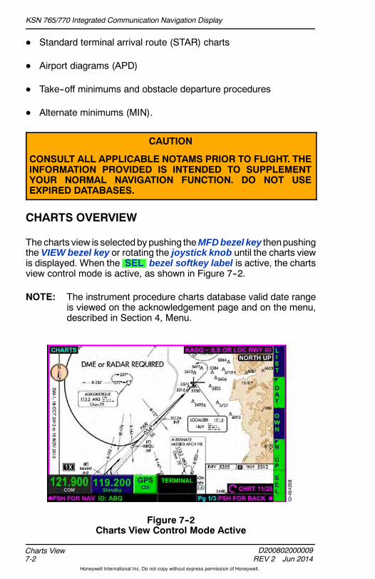
KSN 765/770 Integrated Communication Navigation Display
D200802000009REV 2 Jun 2014
Charts View7-2
Honeywell International Inc. Do not copy without express permission of Honeywell.
D Standard terminal arrival route (STAR) charts
D Airport diagrams (APD)
D Take--off minimums and obstacle departure procedures
D Alternate minimums (MIN).
CAUTION
CONSULT ALL APPLICABLE NOTAMS PRIOR TO FLIGHT. THEINFORMATION PROVIDED IS INTENDED TO SUPPLEMENTYOUR NORMAL NAVIGATION FUNCTION. DO NOT USEEXPIRED DATABASES.
CHARTS OVERVIEW
Thecharts view is selectedby pushing theMFD bezel key thenpushingthe VIEW bezel key or rotating the joystick knob until the charts viewis displayed. When the SEL bezel softkey label is active, the chartsview control mode is active, as shown in Figure 7--2.
NOTE: The instrument procedure charts database valid date rangeis viewed on the acknowledgement page and on the menu,described in Section 4, Menu.
Figure 7--2Charts View Control Mode Active
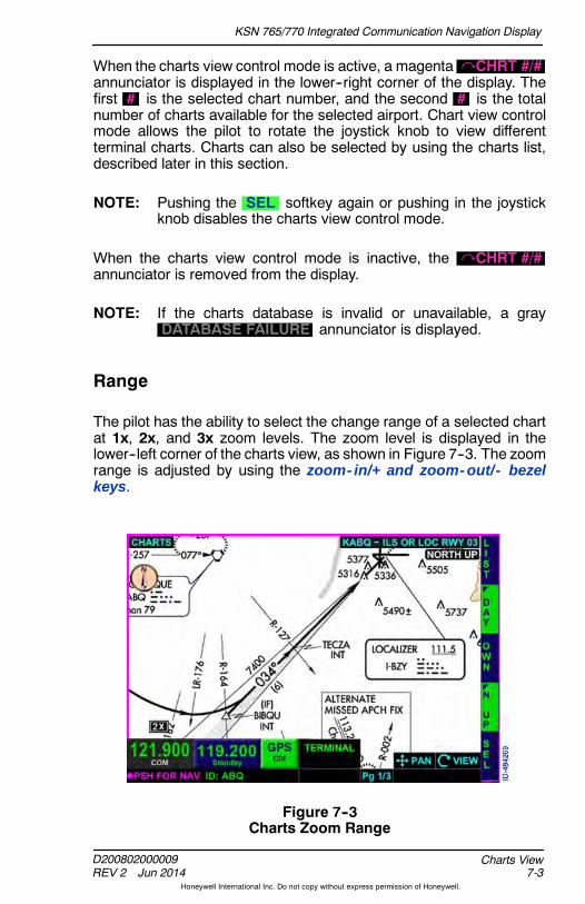
KSN 765/770 Integrated Communication Navigation Display
D200802000009REV 2 Jun 2014 7-3
Charts View
Honeywell International Inc. Do not copy without express permission of Honeywell.
When the charts view control mode is active, a magenta CHRT #/#annunciator is displayed in the lower--right corner of the display. Thefirst # is the selected chart number, and the second # is the totalnumber of charts available for the selected airport. Chart view controlmode allows the pilot to rotate the joystick knob to view differentterminal charts. Charts can also be selected by using the charts list,described later in this section.
NOTE: Pushing the SEL softkey again or pushing in the joystickknob disables the charts view control mode.
When the charts view control mode is inactive, the CHRT #/#annunciator is removed from the display.
NOTE: If the charts database is invalid or unavailable, a grayDATABASE FAILURE annunciator is displayed.
Range
The pilot has the ability to select the change range of a selected chartat 1x, 2x, and 3x zoom levels. The zoom level is displayed in thelower--left corner of the charts view, as shown in Figure 7--3. The zoomrange is adjusted by using the zoom- in/+ and zoom- out/- bezelkeys.
Figure 7--3Charts Zoom Range

KSN 765/770 Integrated Communication Navigation Display
D200802000009REV 2 Jun 2014
Charts View7-4
Honeywell International Inc. Do not copy without express permission of Honeywell.
Panning
Panning canbeactivatedon charts bymomentarily pushing the joystickknob in any direction. Unlike the navigation map display, the cursor isnot displayed on the charts view when panning is active.
NOTE: When panning becomes active, the touchscreen can beusedto control panning.
When panning becomes inactive and the current aircraft symbol is noton the chart, the selected chart centers within the window. Whenpanning becomes inactive and the current aircraft symbol is on thechart, the current aircraft symbol is centered within the window.

KSN 765/770 Integrated Communication Navigation Display
D200802000009REV 2 Jun 2014 7-5
Charts View
Honeywell International Inc. Do not copy without express permission of Honeywell.
Charts List
When the LIST bezel softkey label is active, available charts for aparticular airport are listed, as shown in Figure 7--4. The last selectedchart identifier is displayed at power--up.
NOTE: Only the charts applicable to the selected airport are listed.
Figure 7--4Charts List
When available, the following charts are displayed and listed in theorder shown in Figure 7--5.
Figure 7--5Chart Information Selection
KSN 765/770 Integrated Communication Navigation Display
D200802000009REV 2 Jun 2014
Charts View7-6
Honeywell International Inc. Do not copy without express permission of Honeywell.
To enter the procedures list for the displayed airport, toggle the joystickknob down to the procedures list and then rotate the joystick knob.Pushing in the joystick knob selects the highlighted chart.
A prefix is displayed before the chart heading to indicate the chart type(i.e., MIN for takeoff minimums, alternate minimums, and radarminimums, STAR and arrival procedures, IAP for instrumentapproach procedures, APD for the airport diagram, and DP fordeparture procedures).
To change the airport and the associated charts, rotate and toggle thejoystick knob to enter thedesirednewairport identifier. Alternatively, thetouchscreen can beused to change theairport identifier by touching theairport selection box at the top of the airport list and using theQWERTYkeypad to enter the new airport identifier.
DEP, DEST, AND NRST BEZEL SOFTKEY LABELS
When the LIST bezel softkey label is active, the second, third andfourth right bezel softkey labels display DEP , DEST , and NRSTrespectively.
D DEP -- Pushing the DEP bezel softkey automatically fills theidentifier of the airport (with an instrument approach procedure)closest to the startup latitude/longitude point. In addition, theSELECTING DEPARTURE message is displayed for 1 second.
D DEST -- Pushing the DEST bezel softkey automatically fills theidentifier of the airport (with an instrument approach procedure)closest to the destination latitude/longitude point or the airportclosest to the startup latitude/longitude point when a destination isnot entered in the flight plan. In addition, theSELECTING DESTINATION message is displayed for 1 second.
D NRST -- Pushing the NRST bezel softkey automatically fills theidentifier of the nearest airport (with an instrument approachprocedure) to the aircraft present position. At startup, this is thesame as the DEP bezel softkey. In addition, theSELECTING NEAREST message is displayed for 1 second.
NOTES: 1. The destination latitude/longitude is basedon the flightplan of the FMS.
2. The DEP , DEST , and NRST bezel softkey labelsare removed from display if the aircraft positionbecomes unavailable.

KSN 765/770 Integrated Communication Navigation Display
D200802000009REV 2 Jun 2014 7-7
Charts View
Honeywell International Inc. Do not copy without express permission of Honeywell.
Day and Night Display
The pilot has the ability to select two chart styles:
D Night chart display
D Day chart display.
When the NITE bezel softkey label is active, the chart is displayedwithwhite text on a black background, as shown in Figure 7--6. This displayis conducive to flying at night.
Figure 7--6Night Chart Display

KSN 765/770 Integrated Communication Navigation Display
D200802000009REV 2 Jun 2014
Charts View7-8
Honeywell International Inc. Do not copy without express permission of Honeywell.
When the DAY bezel softkey label is active, the chart is displayedwithblack text on a white background, as shown in Figure 7--7. This displayis conducive to flying during the day.
Figure 7--7Day Chart Display
The last pilot--selection is retained following a power cycle.

KSN 765/770 Integrated Communication Navigation Display
D200802000009REV 2 Jun 2014 7-9
Charts View
Honeywell International Inc. Do not copy without express permission of Honeywell.
Current Aircraft (Ownship)
The pilot can overlay the Ownship symbol on airportdiagrams and instrument approach procedures.When the OWN bezel softkey label is active, theOwnship symbol is displayed. When the aircraft islocated within the valid display area of the airport
diagram or a geo--referenced instrument approach procedure with theGPS track (greater than 30--knot groundspeed) or heading informationvalid, the Ownship symbol is displayed and oriented appropriately.
When theheading input is not installed or if a headingfailure occurs, and the GPS track is not valid or lessthan 30--knot groundspeed, the aircraft symbol isremoved from the display and only the cyan circleremains. The cyan circle displays approximate GPS
location, however heading orientation is not given. When GPS track isvalid and thegroundspeed is greater than30 knots, the ownship symbolis displayed regardless of not having a heading input or having aheading failure.
NOTE: The plan--view portion of geo--referenced instrumentapproach procedures can display the Ownship symbol. TheOwnship symbol display is limited to the to scale area ofterminal procedures. Most standard instrument departure(SIDs), STARS, DPs, and ODPs are not to scale andtherefore cannot display the Ownship symbol.
CAUTION
OWNSHIP OVERLAY ON INSTRUMENT APPROACHPROCEDURES IS INTENDED TO ENHANCE SITUATIONALAWARENESS ONLY AND IS NOT TO BE USED FORNAVIGATION.
Airport diagrams are specifically designed to assist in the movement ofground traffic at locations with complex runway/taxiway configurations.Airport diagrams are not intended to be used for approach and landingor departure operations.
In some instances the aircraft symbol is not available for display or isnot on the chart. When this occurs, there are two annunciators that aredisplayed in the chart view:
D OWNSHIP NOT AVAILABLE -- Indicates the ownship symbolcannot be displayed on the selected terminal procedure.
D OWNSHIP OFF CHART -- Indicates the ownship symbol is off thecurrently displayed terminal procedure.

KSN 765/770 Integrated Communication Navigation Display
D200802000009REV 2 Jun 2014
Charts View7-10
Honeywell International Inc. Do not copy without express permission of Honeywell.
Table 7--1 lists the possible scenarios in which one of the previouslymentioned annunciators is displayed.
Table 7--1Ownship Annunciators
SelectedChart
OWN BezelSoftkey Label
State
CurrentAircraftSymbol Annunciator
Non Geo--ReferencedAPD, DP,DPO, IAP, orSTAR
Active Not displayed OWNSHIPNOT
AVAILABLE
Non Geo--ReferencedAPD, DP,DPO, IAP, orSTAR
Inactive Not displayed No annunciator
Geo--ReferencedAPD, DP, IAP,DPO or STARand GPSposition isavailable
Active Not visible OWNSHIPOFF CHART
Geo--ReferencedAPD, DP, IAP,DPO or STARand GPSposition isavailable
Active Displayed No annunciator
Geo--ReferencedAPD, DP, IAP,DPO or STARand GPSposition is notavailable
Active Not visible OWNSHIPNOT
AVAILABLE

KSN 765/770 Integrated Communication Navigation Display
D200802000009REV 2 Jun 2014 7-11
Charts View
Honeywell International Inc. Do not copy without express permission of Honeywell.
Table 7--1 (cont)Ownship Annunciators
SelectedChart Annunciator
CurrentAircraftSymbol
OWN BezelSoftkey Label
State
Geo--ReferencedAPD, DP, IAP,DPO or STAR
Inactive Not displayed No annunciator
Other thanAPD, DP,DPO, IAP orSTAR
Not displayed Not displayed No annunciator
NOTE: If the GPS is invalid or has failed, an amber GPS FAILannunciator is displayed.
Chart Orientation
The charts view orientation is selected with the chart orientation bezelsoftkey label in 4R. The following is a list of bezel softkey labels that thepilot can toggle through:
D NORM -- Normal--up
NOTE: The normal--up orientation is the same as thepresentation providedby thenormal orientation of a paperchart.
D N UP -- True north--up
D HDG -- Heading--up
NOTE: The HDG bezel softkey label is only displayed when aheading source is configured and available. When aheading source is not configured or available, the HDGbezel softkey label is not displayed.
D TRK -- Track--up.
NOTE: The chart orientation bezel softkey labels at 4R are notdisplayed when panning mode is active.
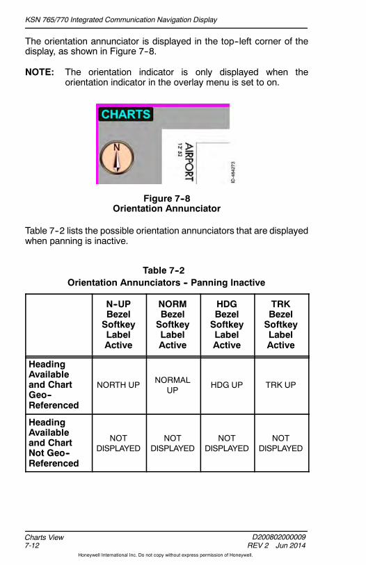
KSN 765/770 Integrated Communication Navigation Display
D200802000009REV 2 Jun 2014
Charts View7-12
Honeywell International Inc. Do not copy without express permission of Honeywell.
The orientation annunciator is displayed in the top--left corner of thedisplay, as shown in Figure 7--8.
NOTE: The orientation indicator is only displayed when theorientation indicator in the overlay menu is set to on.
Figure 7--8Orientation Annunciator
Table 7--2 lists the possible orientation annunciators that are displayedwhen panning is inactive.
Table 7--2Orientation Annunciators -- Panning Inactive
N--UPBezelSoftkeyLabelActive
NORMBezelSoftkeyLabelActive
HDGBezelSoftkeyLabelActive
TRKBezelSoftkeyLabelActive
HeadingAvailableand ChartGeo--Referenced
NORTH UP NORMALUP
HDG UP TRK UP
HeadingAvailableand ChartNot Geo--Referenced
NOTDISPLAYED
NOTDISPLAYED
NOTDISPLAYED
NOTDISPLAYED

KSN 765/770 Integrated Communication Navigation Display
D200802000009REV 2 Jun 2014 7-13
Charts View
Honeywell International Inc. Do not copy without express permission of Honeywell.
Table 7--2 (cont)Orientation Annunciators -- Panning Inactive
TRKBezelSoftkeyLabelActive
HDGBezelSoftkeyLabelActive
NORMBezelSoftkeyLabelActive
N--UPBezelSoftkeyLabelActive
Heading NotAvailable orInvalid, TrackAvailable,and ChartGeo--Referenced
NORTH UP(HDG FAIL)
NORMALUP (HDGFAIL)
NOTDISPLAYED
TRK UP(HDG FAIL)
Heading NotAvailable orInvalid, TrackAvailable,and ChartNot Geo--Referenced
NOTDISPLAYED
NOTDISPLAYED
NOTDISPLAYED
NOTDISPLAYED
Heading andTrack NotAvailable orInvalid
NORTH UP(HDG FAIL)
NORMALUP (HDGFAIL)
NOTDISPLAYED
NOTDISPLAYED
NOTES: 1. When the chart orientation is HDG UP when headingbecomes not available or invalid, TRK UP orientationis selected when the selected chart supports theNormalUp andNorth Uporientations or theNormalUpandNorth Up orientations are the same in the selectedchart.
2. When the chart orientation is TRK UP when headingor track status becomes not available or invalid,NORMAL UP orientation is selected when the NormalUp and North Up orientations are not the same in theselected chart.
3. When the chart orientation is TRK UP when headingor track status becomes not available or invalid,NORTH UP orientation is selected when the NormalUp and North Up orientations are the same in theselected chart.

KSN 765/770 Integrated Communication Navigation Display
D200802000009REV 2 Jun 2014
Charts View7-14
Honeywell International Inc. Do not copy without express permission of Honeywell.
Table 7--3 lists the possible orientation displays of the charts viewwhenpanning in active.
Table 7--3Orientation Annunciators -- Panning Active
N--UPBezelSoftkeyLabelActive
NORMBezelSoftkeyLabelActive
HDGBezelSoftkeyLabelActive
TRKBezelSoftkeyLabelActive
HeadingAvailableand ChartGeo--Referenced
NORTH UP-- PANMODE
NORMALUP -- PANMODE
PAN MODE PAN MODE
HeadingAvailableand ChartNot Geo--Referenced
NOTDISPLAYED
NOTDISPLAYED
NOTDISPLAYED
NOTDISPLAYED
Heading NotAvailable orInvalid, TrackAvailable,and ChartGeo--Referenced
NORTH UP-- PANMODE
(HDG FAIL)
NORMALUP -- PANMODE
(HDG FAIL)
NOTDISPLAYED
PAN MODE
(HDG FAIL)
Heading NotAvailable orInvalid andChart NotGeo--Referenced
NOTDISPLAYED
NOTDISPLAYED
NOTDISPLAYED
NOTDISPLAYED
Heading andTrack NotAvailable orInvalid
NORTH UP-- PANMODE
(HDG FAIL)
NORMALUP -- PANMODE
(HDG FAIL)
NOTDISPLAYED
NOTDISPLAYED
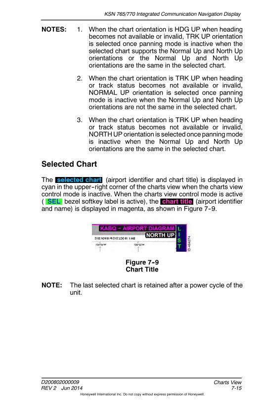
KSN 765/770 Integrated Communication Navigation Display
D200802000009REV 2 Jun 2014 7-15
Charts View
Honeywell International Inc. Do not copy without express permission of Honeywell.
NOTES: 1. When the chart orientation is HDG UP when headingbecomes not available or invalid, TRK UP orientationis selected once panning mode is inactive when theselected chart supports the Normal Up and North Uporientations or the Normal Up and North Uporientations are the same in the selected chart.
2. When the chart orientation is TRK UP when headingor track status becomes not available or invalid,NORMAL UP orientation is selected once panningmode is inactive when the Normal Up and North Uporientations are not the same in the selected chart.
3. When the chart orientation is TRK UP when headingor track status becomes not available or invalid,NORTHUPorientation is selectedoncepanningmodeis inactive when the Normal Up and North Uporientations are the same in the selected chart.
Selected Chart
The selected chart (airport identifier and chart title) is displayed incyan in the upper--right corner of the charts view when the charts viewcontrol mode is inactive. When the charts view control mode is active( SEL bezel softkey label is active), the chart title (airport identifierand name) is displayed in magenta, as shown in Figure 7--9.
Figure 7--9Chart Title
NOTE: The last selected chart is retained after a power cycle of theunit.

KSN 765/770 Integrated Communication Navigation Display
D200802000009REV 2 Jun 2014
Charts View7-16
Honeywell International Inc. Do not copy without express permission of Honeywell.
AIRPORT DIAGRAM POP--UP FUNCTION
The airport diagram pop--up feature setting is controlled using theAPD QUICK ACCESS FUNCTION menu item on the menu. TheAPD QUICK ACCESS FUNCTION has three settings: AUTO ,MANUAL , and OFF .
NOTE: The setting is retained after a power cycle of the unit.
When the AUTO airport diagram pop--up function is active, the airportdiagram is automatically displayed at startup or after landing. The afterlanding condition is met when the indicated airspeed and groundspeedtransition from greater than 30 knots to less than 30 knots. The airportclosest to the current latitude/longitude is automatically displayed(when available).
In the MANUAL setting, at startup or after landing, the airport diagramcan be selected by pushing the PUSH FOR AIRPORT DIAGRAMbezel softkey or touchscreen button.
NOTE: The AUTO and MANUAL settings perform no actionswhen there is no airport diagram for the current aircraftlocation.
When the airport diagram is displayed, the BACK touchscreen buttonis displayed in the left--side of the display. Pushing the BACK bezelsoftkey or touchscreen button returns to the previous active screendisplay.
In the OFF setting, the airport diagram must be manually selectedusing the normal selection procedures.

KSN 765/770 Integrated Communication Navigation Display
D200802000009REV 2 Jun 2014 7-17
Charts View
Honeywell International Inc. Do not copy without express permission of Honeywell.
Manual Airport Diagram Pop--Up Function
When the MANUAL airport diagram pop--up function is active, afterstartup or when the indicated airspeed or groundspeed transition fromgreater than 30 knots to less than 30 knots,APD LOAD Airport Diagram is displayed in the top--center of thescreen the PUSH FOR AIRPORT DIAGRAM touchscreen button isdisplayed in 1R, and the CLEAR touchscreen softkey is displayed in2R, as shown in Figure 7--10.
Figure 7--10Manual Airport Diagram Pop--Up
PUSH FOR AIRPORT DIAGRAM or CLEAR must be pushedbefore this screen can be exited.
Pushing the PUSH FOR AIRPORT DIAGRAM touchscreen softkeydisplays the airport diagram for the closest to the currentlatitude/longitude (when available).
Pushing the CLEAR touchscreen softkey clears the airport diagramfunction and allows the pilot to continue using the previously selecteddisplay.
The airport diagram is removed from display when the indicatedairspeed or groundspeed transitions from less than 30 knots to greaterthan 30 knots.

KSN 765/770 Integrated Communication Navigation Display
D200802000009REV 2 Jun 2014
Charts View7-18
Honeywell International Inc. Do not copy without express permission of Honeywell.
Blank Page
KSN 765/770 Integrated Communication Navigation Display
D200802000009REV 2 Jun 2014 8-1
Terrain View
Honeywell International Inc. Do not copy without express permission of Honeywell.
8. Terrain View
INTRODUCTION
The terrain view depiction is threat--based and highlights threateningterrain in various colors depending on the vertical proximity of theterrain to the current aircraft altitude. A terrain database is used toprovide terrain and obstacle awareness.
Terrain cells are basedon thedifferencebetween the terrain andaircraftcomputed baro--corrected or GPS (not pressure altitude) height inmean sea level (MSL). Accurate relative terrain presentation dependsentirely on an accurate barometric altimeter setting.
CAUTION
TERRAIN INFORMATION IS FOR AWARENESS ONLY. DO NOTMANEUVER BASED SOLELY ON THIS INFORMATION.
The terrain effectivity date is viewed on the power--up display and onthe menu, described in Section 4, Menu.
TERRAIN VIEW OVERVIEW
There are two ways in which terrain is displayed:
D Terrain overlay on the navigation map
D Terrain view in full screen, split screen, and thumbnail layouts.
The terrain overlay is described in Section 6, Navigation Map View.
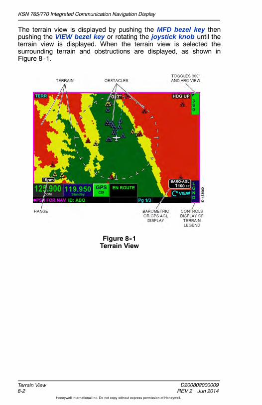
KSN 765/770 Integrated Communication Navigation Display
D200802000009REV 2 Jun 2014
Terrain View8-2
Honeywell International Inc. Do not copy without express permission of Honeywell.
The terrain view is displayed by pushing the MFD bezel key thenpushing the VIEW bezel key or rotating the joystick knob until theterrain view is displayed. When the terrain view is selected thesurrounding terrain and obstructions are displayed, as shown inFigure 8--1.
Figure 8--1Terrain View

KSN 765/770 Integrated Communication Navigation Display
D200802000009REV 2 Jun 2014 8-3
Terrain View
Honeywell International Inc. Do not copy without express permission of Honeywell.
Terrain View Display Modes
The pilot can select two terrain view modes by activating either of thefollowing bezel softkey labels.
D ARC -- Displays arc view mode
D 360 -- Displays 360 compass view mode.
The display mode is indicated by the active bezel softkey label in theupper--right corner of the terrain view. Figure 8--2 shows the arc viewmode as indicated by ARC displayed as theupper--right bezel softkeylabel.
Figure 8--2Terrain View -- Arc
In arc or 360 compass mode, the range scale is selected with thezoom- in/+ and zoom- out/- bezel keys, such that the outer radius ofthe primary range ring represents 5 , 10 , 15 , 20 , 30 , 40 ,60 , 80 , and 100 nautical miles (NM) from the current aircraftposition.
NOTE: The terrain view display range setting is retained following apower cycle.
A magnetic GPS ground track is displayed with a dashed cyan line( ------ ) from the current aircraft to the range ring, in either the arc or360 compass mode.

KSN 765/770 Integrated Communication Navigation Display
D200802000009REV 2 Jun 2014
Terrain View8-4
Honeywell International Inc. Do not copy without express permission of Honeywell.
Terrain View Heading and Track
When in the terrain view and theheading is available, HDG UP isdisplayed in the upper--right corner ofthe terrain view.
The terrain view uses the magneticheading from themagnetic ground trackof the internal global positioning system(GPS) if the heading of the aircraft isinvalid or unavailable and TRK UP(HDG FAIL) is displayed in theupper--right corner of the terrain view.
In heading--up or track--up mode, thedirection of flight value displays theheading/track with a resolution of1 degree and a range of 1 to360 degrees.

KSN 765/770 Integrated Communication Navigation Display
D200802000009REV 2 Jun 2014 8-5
Terrain View
Honeywell International Inc. Do not copy without express permission of Honeywell.
Terrain View -- Above Ground Level (AGL) Display
When configured to receive correctedbarometric altitude and correctedbarometric altitude is available andvalid, the current height AGL, ascomputed from baro--corrected altitudeand the terrain height directly below theaircraft, is shown in the BARO--AGLbox in the lower--right of the display.
NOTE: In thumbnail views, the annunciation is shown as AGL .
When corrected barometric altitude isnot available, not configured, or invalidand GPS altitude is available and valid,the current height AGL, as computedfrom the GPS altitude and the terrainheight directly below the aircraft, isshown in the GPS--AGL box in thelower--right of the display.
NOTE: In thumbnail views, the annunciation is shown as GSL .
The AGL values are displayed and rounded down to the nearesthundreds of feet (i.e., 899 feet is rounded to 800 feet).
NOTE: The AGL value is not displayed if the GPS positioninformation is not available.
CAUTION
CORRECT BAROMETRIC PRESSURE IS ESSENTIAL TOACCURATE TERRAIN DEPICTION.
The AGL value is dashed ( ---------- )when there is no terrain coverage forthe present position, or when the AGLvalue is above 51,000 feet or below500 feet.
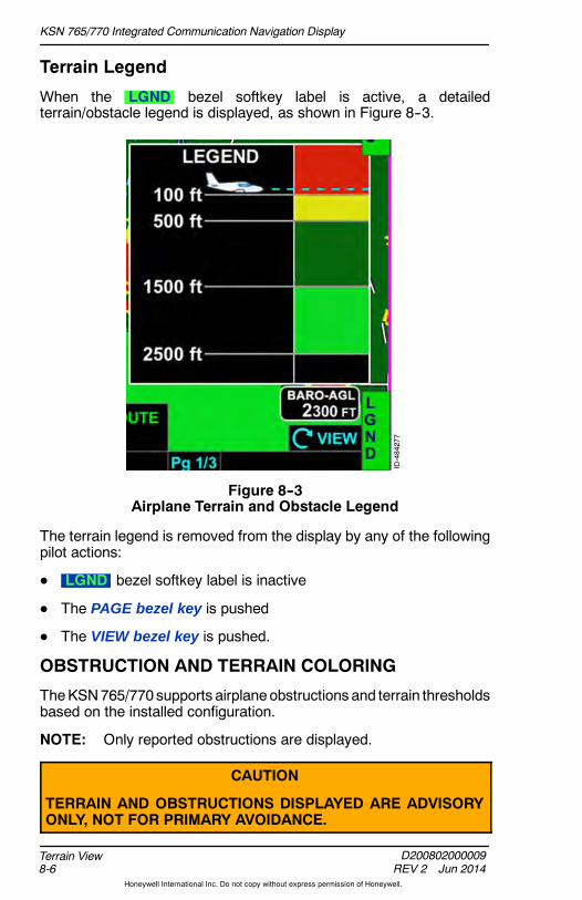
KSN 765/770 Integrated Communication Navigation Display
D200802000009REV 2 Jun 2014
Terrain View8-6
Honeywell International Inc. Do not copy without express permission of Honeywell.
Terrain Legend
When the LGND bezel softkey label is active, a detailedterrain/obstacle legend is displayed, as shown in Figure 8--3.
Figure 8--3Airplane Terrain and Obstacle Legend
The terrain legend is removed from the display by any of the followingpilot actions:
D LGND bezel softkey label is inactive
D The PAGE bezel key is pushed
D The VIEW bezel key is pushed.
OBSTRUCTION AND TERRAIN COLORING
TheKSN765/770 supports airplaneobstructions and terrain thresholdsbased on the installed configuration.
NOTE: Only reported obstructions are displayed.
CAUTION
TERRAIN AND OBSTRUCTIONS DISPLAYED ARE ADVISORYONLY, NOT FOR PRIMARY AVOIDANCE.

KSN 765/770 Integrated Communication Navigation Display
D200802000009REV 2 Jun 2014 8-7
Terrain View
Honeywell International Inc. Do not copy without express permission of Honeywell.
Obstruction Coloring
Obstructions are displayed on the terrain view within 40 NM of theownship, as an inverted colored V symbol, relative to the ownshipaltitude. Figure 8--4 shows the obstruction height symbology for smalltowers, tall towers, and group obstructions.
Figure 8--4Obstruction Height
Obstructions 200 feet AGL and higher are displayed on the navigationmap overly and terrain view. Table 8--1 lists obstruction thresholds forairplane installations.
Table 8--1Obstruction Thresholds
Obstruction Thresholds Color
Airplane
Obstruction is between 1,000 feetand 600 feet below the currentaircraft.
Blue
AirplaneObstruction is between 600 feet and200 feet below the current aircraft.
Yellow
Obstruction is above the currentaircraft or within 200 feet below thealtitude of the current aircraft.
Red
NOTE: Values include a safety threshold of 100 feet.
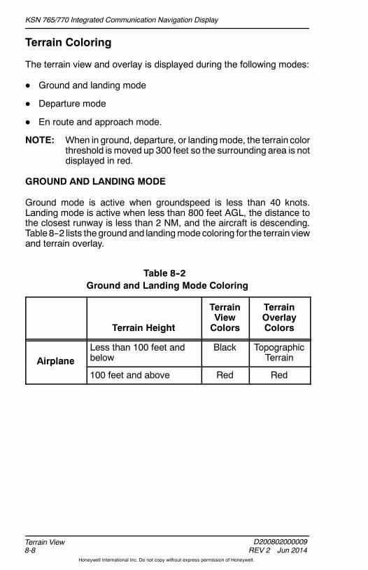
KSN 765/770 Integrated Communication Navigation Display
D200802000009REV 2 Jun 2014
Terrain View8-8
Honeywell International Inc. Do not copy without express permission of Honeywell.
Terrain Coloring
The terrain view and overlay is displayed during the following modes:
D Ground and landing mode
D Departure mode
D En route and approach mode.
NOTE: When in ground, departure, or landingmode, the terrain colorthreshold is moved up 300 feet so the surrounding area is notdisplayed in red.
GROUND AND LANDING MODE
Ground mode is active when groundspeed is less than 40 knots.Landing mode is active when less than 800 feet AGL, the distance tothe closest runway is less than 2 NM, and the aircraft is descending.Table 8--2 lists theground and landingmodecoloring for the terrain viewand terrain overlay.
Table 8--2Ground and Landing Mode Coloring
Terrain Height
TerrainViewColors
TerrainOverlayColors
AirplaneLess than 100 feet andbelow
Black TopographicTerrainAirplane
100 feet and above Red Red
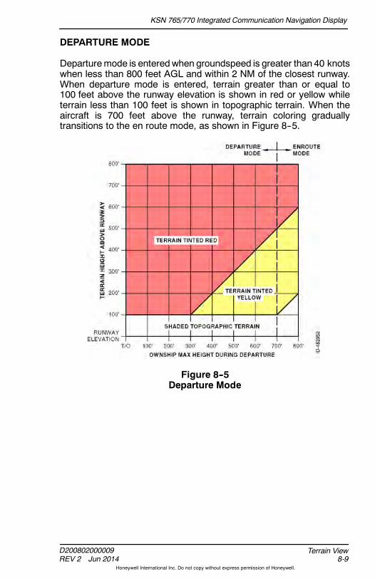
KSN 765/770 Integrated Communication Navigation Display
D200802000009REV 2 Jun 2014 8-9
Terrain View
Honeywell International Inc. Do not copy without express permission of Honeywell.
DEPARTURE MODE
Departuremode is enteredwhen groundspeed is greater than 40 knotswhen less than 800 feet AGL and within 2 NM of the closest runway.When departure mode is entered, terrain greater than or equal to100 feet above the runway elevation is shown in red or yellow whileterrain less than 100 feet is shown in topographic terrain. When theaircraft is 700 feet above the runway, terrain coloring graduallytransitions to the en route mode, as shown in Figure 8--5.
Figure 8--5Departure Mode
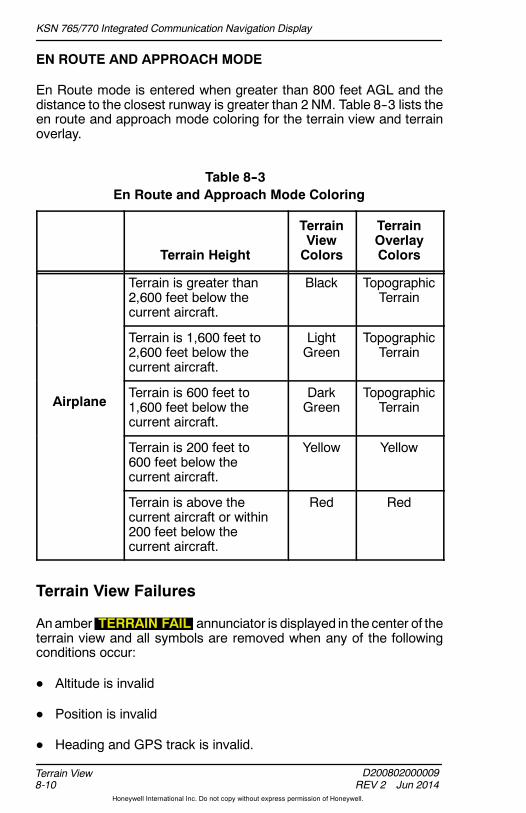
KSN 765/770 Integrated Communication Navigation Display
D200802000009REV 2 Jun 2014
Terrain View8-10
Honeywell International Inc. Do not copy without express permission of Honeywell.
EN ROUTE AND APPROACH MODE
En Route mode is entered when greater than 800 feet AGL and thedistance to the closest runway is greater than 2 NM. Table 8--3 lists theen route and approach mode coloring for the terrain view and terrainoverlay.
Table 8--3En Route and Approach Mode Coloring
Terrain Height
TerrainViewColors
TerrainOverlayColors
Terrain is greater than2,600 feet below thecurrent aircraft.
Black TopographicTerrain
Terrain is 1,600 feet to2,600 feet below thecurrent aircraft.
LightGreen
TopographicTerrain
AirplaneTerrain is 600 feet to1,600 feet below thecurrent aircraft.
DarkGreen
TopographicTerrain
Terrain is 200 feet to600 feet below thecurrent aircraft.
Yellow Yellow
Terrain is above thecurrent aircraft or within200 feet below thecurrent aircraft.
Red Red
Terrain View Failures
Anamber TERRAIN FAIL annunciator is displayed in the center of theterrain view and all symbols are removed when any of the followingconditions occur:
D Altitude is invalid
D Position is invalid
D Heading and GPS track is invalid.

KSN 765/770 Integrated Communication Navigation Display
D200802000009REV 2 Jun 2014 9-1
Traffic View
Honeywell International Inc. Do not copy without express permission of Honeywell.
9. Traffic View
INTRODUCTION
This section describes the traffic view. Traffic awareness is anoptionalfeature and requires an external traffic sensor. When the KSN 765/770is configured with one of the following traffic sensors, the unit candisplay traffic information:
D BendixKing TPU--66A
D BendixKing KTA--810/910
D BendixKing KMH 820/920
D BendixKing KTA 74
D Avidyne 9900BX
D Garmin GTX--330
D L--3 Skywatcht TRC--497 and HP TRC--899.
WARNING
TIS AND TAS CANNOT GIVE ALERTS FOR TRAFFICCONFLICTS FOR TARGET AIRCRAFT WITHOUT OPERATINGTRANSPONDERS.
Traffic Information System (TIS) coverage is limited to specific areaslisted in the Aeronautical Information Manual (AIM). TIS uses a groundsurveillance--based radar system that provides traffic advisories andproximity alerts to aircraft equipped with mode A, C, and Stransponders with an altitude encoder and a means to display theairborne traffic.
A traffic advisory or proximity alert is given to a TIS--equipped aircraftby a ground--based surveillance radar system. TIS provides relativebearing, relative range, relative altitude, heading, altitude trends, andtraffic status (threatening or proximity) of up to eight intruder aircraftwithin a specified TIS airspace volume.
NOTE: See the AIM for detailed information about TIS requirements,capabilities, and limitations.
Traffic Awareness System (TAS) is an active, self--contained systemthat detects other aircraft with mode 3A transponders. TAS providestraffic advisories and proximity alerts for any aircraft equipped with atransponder, anywhere it flies.
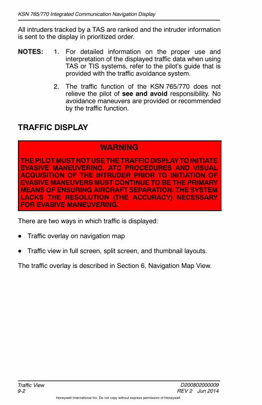
KSN 765/770 Integrated Communication Navigation Display
D200802000009REV 2 Jun 2014
Traffic View9-2
Honeywell International Inc. Do not copy without express permission of Honeywell.
All intruders tracked by a TAS are ranked and the intruder informationis sent to the display in prioritized order.
NOTES: 1. For detailed information on the proper use andinterpretation of the displayed traffic data when usingTAS or TIS systems, refer to the pilot’s guide that isprovided with the traffic avoidance system.
2. The traffic function of the KSN 765/770 does notrelieve the pilot of see and avoid responsibility. Noavoidance maneuvers are provided or recommendedby the traffic function.
TRAFFIC DISPLAY
WARNING
THEPILOTMUSTNOTUSETHETRAFFICDISPLAYTO INITIATEEVASIVE MANEUVERING. ATC PROCEDURES AND VISUALACQUISITION OF THE INTRUDER PRIOR TO INITIATION OFEVASIVEMANEUVERSMUST CONTINUE TO BE THE PRIMARYMEANS OF ENSURING AIRCRAFT SEPARATION. THE SYSTEMLACKS THE RESOLUTION (THE ACCURACY) NECESSARYFOR EVASIVE MANEUVERING.
There are two ways in which traffic is displayed:
D Traffic overlay on navigation map
D Traffic view in full screen, split screen, and thumbnail layouts.
The traffic overlay is described in Section 6, Navigation Map View.
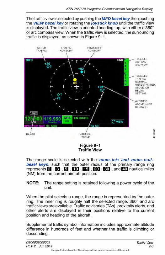
KSN 765/770 Integrated Communication Navigation Display
D200802000009REV 2 Jun 2014 9-3
Traffic View
Honeywell International Inc. Do not copy without express permission of Honeywell.
The traffic view is selected by pushing theMFD bezel key thenpushingthe VIEW bezel key or rotating the joystick knob until the traffic viewis displayed. The traffic view is oriented heading--up, with either a 360or arc compass view. When the traffic view is selected, the surroundingtraffic is displayed, as shown in Figure 9--1.
Figure 9--1Traffic View
The range scale is selected with the zoom- in/+ and zoom- out/-bezel keys, such that the outer radius of the primary range ringrepresents 2 , 3 , 5 , 10 , 15 , 20 , 30 , and 40 nauticalmiles(NM) from the current aircraft position.
NOTE: The range setting is retained following a power cycle of theunit.
When the pilot selects a range, the range is represented by the outerring. The inner ring is roughly half the selected range. 360 and arctraffic views are available. Traffic advisories (TAs), proximity alerts, andother alerts are displayed in their positions relative to the currentposition and heading of the aircraft.
Supplemental traffic symbol information includes approximate altitudedifference in hundreds of feet and whether the traffic is climbing ordescending.
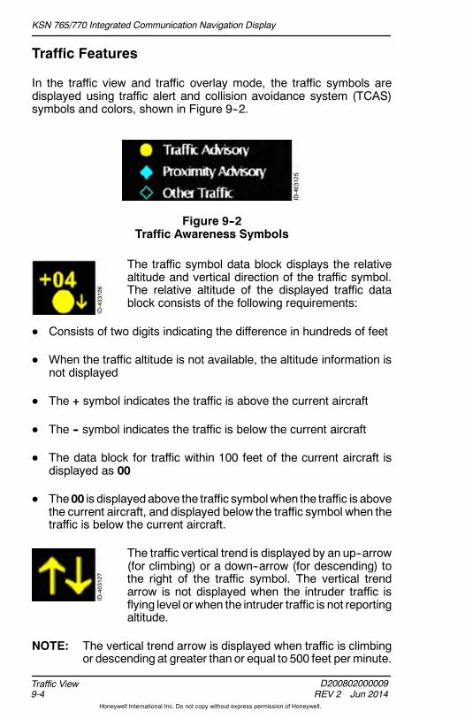
KSN 765/770 Integrated Communication Navigation Display
D200802000009REV 2 Jun 2014
Traffic View9-4
Honeywell International Inc. Do not copy without express permission of Honeywell.
Traffic Features
In the traffic view and traffic overlay mode, the traffic symbols aredisplayed using traffic alert and collision avoidance system (TCAS)symbols and colors, shown in Figure 9--2.
Figure 9--2Traffic Awareness Symbols
The traffic symbol data block displays the relativealtitude and vertical direction of the traffic symbol.The relative altitude of the displayed traffic datablock consists of the following requirements:
D Consists of two digits indicating the difference in hundreds of feet
D When the traffic altitude is not available, the altitude information isnot displayed
D The + symbol indicates the traffic is above the current aircraft
D The -- symbol indicates the traffic is below the current aircraft
D The data block for traffic within 100 feet of the current aircraft isdisplayed as 00
D The00 is displayedabove the traffic symbolwhen the traffic is abovethe current aircraft, and displayed below the traffic symbol when thetraffic is below the current aircraft.
The traffic vertical trend is displayed by an up--arrow(for climbing) or a down--arrow (for descending) tothe right of the traffic symbol. The vertical trendarrow is not displayed when the intruder traffic isflying level orwhen the intruder traffic is not reportingaltitude.
NOTE: The vertical trend arrow is displayed when traffic is climbingor descending at greater than or equal to 500 feet per minute.
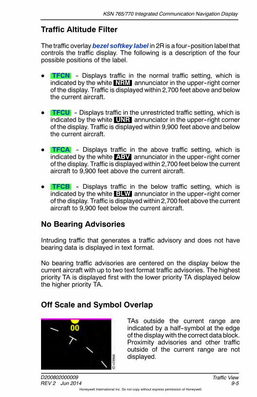
KSN 765/770 Integrated Communication Navigation Display
D200802000009REV 2 Jun 2014 9-5
Traffic View
Honeywell International Inc. Do not copy without express permission of Honeywell.
Traffic Altitude Filter
The traffic overlaybezel softkey label in 2R is a four--position label thatcontrols the traffic display. The following is a description of the fourpossible positions of the label.
D TFCN -- Displays traffic in the normal traffic setting, which isindicated by the white NRM annunciator in the upper--right cornerof the display. Traffic is displayed within 2,700 feet above and belowthe current aircraft.
D TFCU -- Displays traffic in the unrestricted traffic setting, which isindicated by the white UNR annunciator in the upper--right cornerof the display. Traffic is displayedwithin 9,900 feet above and belowthe current aircraft.
D TFCA -- Displays traffic in the above traffic setting, which isindicated by the white ABV annunciator in the upper--right cornerof the display. Traffic is displayedwithin 2,700 feet below the currentaircraft to 9,900 feet above the current aircraft.
D TFCB -- Displays traffic in the below traffic setting, which isindicated by the white BLW annunciator in the upper--right cornerof the display. Traffic is displayedwithin 2,700 feet above the currentaircraft to 9,900 feet below the current aircraft.
No Bearing Advisories
Intruding traffic that generates a traffic advisory and does not havebearing data is displayed in text format.
No bearing traffic advisories are centered on the display below thecurrent aircraft with up to two text format traffic advisories. The highestpriority TA is displayed first with the lower priority TA displayed belowthe higher priority TA.
Off Scale and Symbol Overlap
TAs outside the current range areindicated by a half--symbol at the edgeof thedisplaywith the correct data block.Proximity advisories and other trafficoutside of the current range are notdisplayed.
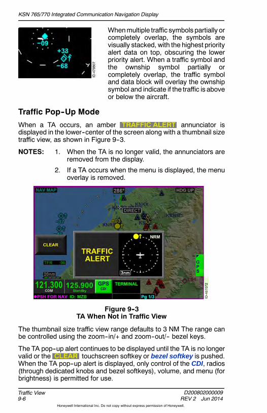
KSN 765/770 Integrated Communication Navigation Display
D200802000009REV 2 Jun 2014
Traffic View9-6
Honeywell International Inc. Do not copy without express permission of Honeywell.
Whenmultiple traffic symbols partially orcompletely overlap, the symbols arevisually stacked, with the highest priorityalert data on top, obscuring the lowerpriority alert. When a traffic symbol andthe ownship symbol partially orcompletely overlap, the traffic symboland data block will overlay the ownshipsymbol and indicate if the traffic is aboveor below the aircraft.
Traffic Pop--Up Mode
When a TA occurs, an amber TRAFFIC ALERT annunciator isdisplayed in the lower--center of the screen along with a thumbnail sizetraffic view, as shown in Figure 9--3.
NOTES: 1. When the TA is no longer valid, the annunciators areremoved from the display.
2. If a TA occurs when the menu is displayed, the menuoverlay is removed.
Figure 9--3TA When Not in Traffic View
The thumbnail size traffic view range defaults to 3 NM The range canbe controlled using the zoom--in/+ and zoom--out/-- bezel keys.
The TA pop--up alert continues to be displayed until the TA is no longervalid or the CLEAR touchscreen softkey or bezel softkey is pushed.When the TA pop--up alert is displayed, only control of the CDI, radios(through dedicated knobs and bezel softkeys), volume, and menu (forbrightness) is permitted for use.

KSN 765/770 Integrated Communication Navigation Display
D200802000009REV 2 Jun 2014 9-7
Traffic View
Honeywell International Inc. Do not copy without express permission of Honeywell.
When a TA occurs and the manual airport diagram pop--up function orback function is active (indicated airspeed and groundspeed less than30 knots), the manual airport diagram pop--up function and backfunction take precedence over the traffic pop--up function because theaircraft is on the ground.
Traffic Status Display
There are four possible states for the TAS traffic sensor status:
D Operational
D Standby
D Test
D Failure.
Traffic symbols are removed and a status annunciation is displayedwhen the traffic sensor is operating in any mode other than operational.
Table 9--1 lists the traffic awareness annunciators when the traffic viewis in full screen, split screen, or thumbnail layoutwith traffic in the rightwindow only.
Table 9--1Traffic Awareness Annunciators -- Full Screen, Split Screen,
or Thumbnail Right Window
Type of Sensor Status Annunciation
TAS Standby TRFC STBY
TAS Test TRFC TEST
TAS Failure TRFC FAIL
TIS Unavailable or out ofrange TRFC UNAVAILABLE
NOTE: The ownship symbol is removed for the above status conditions.

KSN 765/770 Integrated Communication Navigation Display
D200802000009REV 2 Jun 2014
Traffic View9-8
Honeywell International Inc. Do not copy without express permission of Honeywell.
Table 9--2 lists the traffic awareness annunciators when the traffic viewis in the thumbnail layout and the traffic view is selected in the top orbottom windows. Table 9--2 also list the traffic awareness annunciatorswhen the traffic overlay is active.
Table 9--2Traffic Awareness Annunciators -- Top or BottomThumbnail Window or Traffic Overlay Active
Type of Sensor Status Annunciation
TAS Standby
TAS Test TRFC TEST
TAS Failure
TIS Unavailable or out ofrange TRFC UNAV
NOTE: The ownship symbol is removed for the above status conditions.
TIS traffic is normally displayed in real time. When the traffic sensorinformation has not been refreshed for 6 seconds, the TRFC COASTannunciation and age indicator are displayed. After 12 seconds with noupdates, the age indicator continues to be displayed and aTRFC RMVD (traffic removed) annunciator is displayed.
If the GPS fails or heading is invalid or unavailable, the traffic statusbecomes failure.
KSN 765/770 Integrated Communication Navigation Display
D200802000009REV 2 Jun 2014 10-1
Datalink Weather View
Honeywell International Inc. Do not copy without express permission of Honeywell.
10. Datalink Weather View
INTRODUCTION
Datalink weather provides graphical and textual descriptions ofweather--related information received fromXMWXSatelliteweather forthe continental United States, Puerto Rico, and parts of Canada.
NOTE: A separate subscription and sensor is required for XM WXSatellite weather.
Each page within the datalink weather view can display one or moreweather products using bezel softkeys to select the products.
CAUTION
THE USE OF THE DATALINK WEATHER VIEW IS FORLONG--RANGE PLANNING PURPOSES ONLY, NOTSHORT--RANGE AVOIDANCE ADVICE. DO NOT USEINFORMATION PROVIDED TO PENETRATE WEATHER,THUNDERSTORMS, CELLS, OR LINES OF CELLS. THEAERONAUTICAL INFORMATION MANUAL RECOMMENDSAVOIDING THUNDERSTORMS IDENTIFIED AS SEVERE ORGIVING AN INTENSE RADAR ECHO BY AT LEAST 20 MILES.
There are two ways in which XM weather is displayed:
D NEXRAD and lightning overlay on navigation map
D Datalink weather view.
The weather overlay on the navigation map is described in Section 6,Navigation Map View.
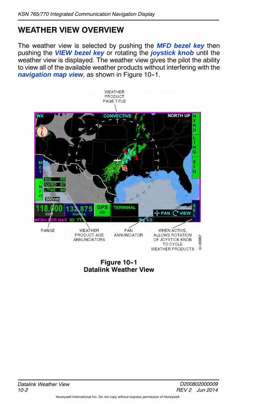
KSN 765/770 Integrated Communication Navigation Display
D200802000009REV 2 Jun 2014
Datalink Weather View10-2
Honeywell International Inc. Do not copy without express permission of Honeywell.
WEATHER VIEW OVERVIEW
The weather view is selected by pushing the MFD bezel key thenpushing the VIEW bezel key or rotating the joystick knob until theweather view is displayed. The weather view gives the pilot the abilityto view all of the available weather products without interfering with thenavigation map view, as shown in Figure 10--1.
Figure 10--1Datalink Weather View
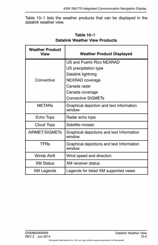
KSN 765/770 Integrated Communication Navigation Display
D200802000009REV 2 Jun 2014 10-3
Datalink Weather View
Honeywell International Inc. Do not copy without express permission of Honeywell.
Table 10--1 lists the weather products that can be displayed in thedatalink weather view.
Table 10--1Datalink Weather View Products
Weather ProductView Weather Product Displayed
Convective
US and Puerto Rico NEXRADUS precipitation typeDatalink lightningNEXRAD coverageCanada radarCanada coverageConvective SIGMETs
METARs Graphical depiction and text informationwindow
Echo Tops Radar echo tops
Cloud Tops Satellite mosaic
AIRMET/SIGMETs Graphical depictions and text Informationwindow
TFRs Graphical depictions and text Informationwindow
Winds Aloft Wind speed and direction
XM Status XM receiver status
XM Legends Legends for listed XM supported views

KSN 765/770 Integrated Communication Navigation Display
D200802000009REV 2 Jun 2014
Datalink Weather View10-4
Honeywell International Inc. Do not copy without express permission of Honeywell.
Datalink Weather View Orientation
The datalink weather view displays the ownship symbol and flight planoverlaid on a black background, oriented to north--up in a 360 rangering. Table 10--2 lists the possible orientation annunciators that aredisplayed in the upper right corner of the datalink weather view.
NOTE: When the panning view control mode is on in weather view,the cursor is removed from the display.
Table 10--2Weather View Orientation Annunciators
Panning Inactive Panning Active
Heading and GPSGround Track isAvailable
NORTH UP PAN MODE
Heading notAvailable or Invalidand GPS GroundTrack is Available
NORTH UP(HDG FAIL)
PAN MODE(HDG FAIL)
Heading Availableand GPS GroundTrack isUnavailable orInvalid
NORTH UP PAN MODE
Heading and GPSGround TrackUnavailable orInvalid
NORTH UP(HDG FAIL)
PAN MODE(HDG FAIL)
The datalink weather view uses the current heading or current trackfrom theGPS if heading is invalid or unavailable for the ownship symboldisplay.
Following a power cycle, the datalink weather view initializes usingeither current position or last known position if the current position is notavailable.
In order to provide situational awareness, each screen displaysinternational boundaries; state or province boundaries for the UnitedStates, Mexico, and Canada; and water features.
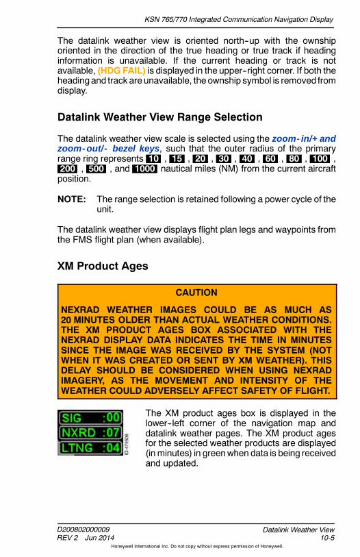
KSN 765/770 Integrated Communication Navigation Display
D200802000009REV 2 Jun 2014 10-5
Datalink Weather View
Honeywell International Inc. Do not copy without express permission of Honeywell.
The datalink weather view is oriented north--up with the ownshiporiented in the direction of the true heading or true track if headinginformation is unavailable. If the current heading or track is notavailable, (HDG FAIL) is displayed in the upper--right corner. If both theheadingand track are unavailable, theownship symbol is removed fromdisplay.
Datalink Weather View Range Selection
The datalink weather view scale is selected using the zoom- in/+ andzoom- out/- bezel keys, such that the outer radius of the primaryrange ring represents 10 , 15 , 20 , 30 , 40 , 60 , 80 , 100 ,200 , 500 , and 1000 nautical miles (NM) from the current aircraftposition.
NOTE: The range selection is retained following a power cycle of theunit.
The datalink weather view displays flight plan legs and waypoints fromthe FMS flight plan (when available).
XM Product Ages
CAUTION
NEXRAD WEATHER IMAGES COULD BE AS MUCH AS20 MINUTES OLDER THAN ACTUAL WEATHER CONDITIONS.THE XM PRODUCT AGES BOX ASSOCIATED WITH THENEXRAD DISPLAY DATA INDICATES THE TIME IN MINUTESSINCE THE IMAGE WAS RECEIVED BY THE SYSTEM (NOTWHEN IT WAS CREATED OR SENT BY XM WEATHER). THISDELAY SHOULD BE CONSIDERED WHEN USING NEXRADIMAGERY, AS THE MOVEMENT AND INTENSITY OF THEWEATHER COULD ADVERSELY AFFECT SAFETY OF FLIGHT.
The XM product ages box is displayed in thelower--left corner of the navigation map anddatalink weather pages. The XM product agesfor the selected weather products are displayed(inminutes) in greenwhen data is being receivedand updated.
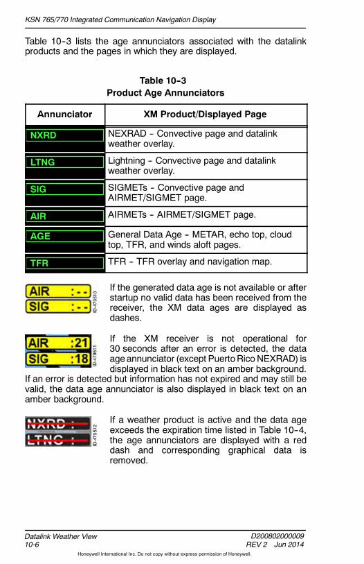
KSN 765/770 Integrated Communication Navigation Display
D200802000009REV 2 Jun 2014
Datalink Weather View10-6
Honeywell International Inc. Do not copy without express permission of Honeywell.
Table 10--3 lists the age annunciators associated with the datalinkproducts and the pages in which they are displayed.
Table 10--3Product Age Annunciators
Annunciator XM Product/Displayed Page
NXRD NEXRAD -- Convective page and datalinkweather overlay.
LTNG Lightning -- Convective page and datalinkweather overlay.
SIG SIGMETs -- Convective page andAIRMET/SIGMET page.
AIR AIRMETs -- AIRMET/SIGMET page.
AGE General Data Age -- METAR, echo top, cloudtop, TFR, and winds aloft pages.
TFR TFR -- TFR overlay and navigation map.
If the generated data age is not available or afterstartup no valid data has been received from thereceiver, the XM data ages are displayed asdashes.
If the XM receiver is not operational for30 seconds after an error is detected, the dataageannunciator (except PuertoRicoNEXRAD) isdisplayed in black text on an amber background.
If an error is detected but information has not expired and may still bevalid, the data age annunciator is also displayed in black text on anamber background.
If a weather product is active and the data ageexceeds the expiration time listed in Table 10--4,the age annunciators are displayed with a reddash and corresponding graphical data isremoved.
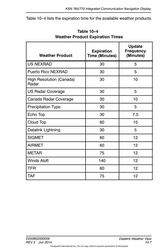
KSN 765/770 Integrated Communication Navigation Display
D200802000009REV 2 Jun 2014 10-7
Datalink Weather View
Honeywell International Inc. Do not copy without express permission of Honeywell.
Table 10--4 lists the expiration time for the available weather products.
Table 10--4Weather Product Expiration Times
Weather ProductExpiration
Time (Minutes)
UpdateFrequency(Minutes)
US NEXRAD 30 5
Puerto Rico NEXRAD 30 5
High Resolution (Canada)Radar
30 10
US Radar Coverage 30 5
Canada Radar Coverage 30 10
Precipitation Type 30 5
Echo Top 30 7.5
Cloud Top 60 15
Datalink Lightning 30 5
SIGMET 60 12
AIRMET 60 12
METAR 75 12
Winds Aloft 140 12
TFR 60 12
TAF 75 12

KSN 765/770 Integrated Communication Navigation Display
D200802000009REV 2 Jun 2014
Datalink Weather View10-8
Honeywell International Inc. Do not copy without express permission of Honeywell.
DATALINK WEATHER PAGES
Thepilot can select any of the followingweather pages from thedatalinkweather page by activating the SEL bezel softkey label and rotatingthe joystick knob:
D Convective page
D METARs page
D Echo tops page
D Cloud tops page
D AIRMET/SIGMETs page
D TFR page
D Winds aloft page
D XM status page.
When the SEL bezel softkey label is active, the weather productselection function is active. Wx X/8 is displayed in the lower--rightcorner of the display, where X indicates current weather productscreen. The selected weather product name is displayed as the headerof eachdatalinkweather page inmagentawhen the SEL bezel softkeylabel is active.
Rotating the joystick knob selects another weather product screen. Thedatalink weather display, bezel softkey labels, header, and Wx X/8label change as different weather product screens are selected.
When the SEL bezel softkey label is inactive, the weather productselection function is exited. Rotating the joystick knob when the SELbezel softkey label is displayed alternates the MFD views (navigationmap, terrain, etc.).

KSN 765/770 Integrated Communication Navigation Display
D200802000009REV 2 Jun 2014 10-9
Datalink Weather View
Honeywell International Inc. Do not copy without express permission of Honeywell.
When the touchscreen is inactive, the weather product page titles areflat and not selectable. When the touchscreen is active, the weatherproduct page title (shown in Figure 10--2 as METARS ) and view title(shown in Figure 10--2 as WEATHER ) become embossed andselectable. When the touchscreen is active and either of the embossedtouchscreen buttons are selected, the weather view page list isdisplayed, as shown in Figure 10--2. Theweather pages can be directlyselected by using the touchscreen to select a weather product from thelist.
Figure 10--2Weather View Page List
The currently displayed weather page is displayed with blue text on agreen background in the list. All other pages are displayed with greentext on a blue background. Any of the pages can be displayed by usingthe touchscreen to select the desired page title and then pushing OKon the touchscreen. The weather view page list is removed after5 seconds of inactivity.
NOTE: The page selection is retained following a power cycle of theunit.

KSN 765/770 Integrated Communication Navigation Display
D200802000009REV 2 Jun 2014
Datalink Weather View10-10
Honeywell International Inc. Do not copy without express permission of Honeywell.
Convective Page
The convective page, shown in Figure 10--3, can display the followingradar coverages:
D US and Puerto Rico NEXRAD
D US precipitation type
D Convective SIGMETs
D Datalink lightning
D Canada radar
D US NEXRAD coverage
D Canada coverage.
Figure 10--3Convective Page
NEXRAD (next--generation radar) detects precipitation andatmospheric movement. NEXRAD is a network of 159 high--resolutionDoppler radars operated by the National Weather Service (NWS), anagency of the National Oceanic and Atmospheric Administration(NOAA), to detect meteorological data for the United States. The datacan be processed and displayed in a mosaic map showing patterns ofprecipitation andmovement. EachNEXRAD radar site has amaximumrange of 250 NM.

KSN 765/770 Integrated Communication Navigation Display
D200802000009REV 2 Jun 2014 10-11
Datalink Weather View
Honeywell International Inc. Do not copy without express permission of Honeywell.
CAUTION
NEXRAD WEATHER IMAGES COULD BE AS MUCH AS20 MINUTES OLDER THAN ACTUAL WEATHER CONDITIONS.THE XM PRODUCT AGES BOX ASSOCIATED WITH THENEXRAD DISPLAY DATA INDICATES THE TIME IN MINUTESSINCE THE IMAGE WAS RECEIVED BY THE SYSTEM (NOTWHEN IT WAS CREATED OR SENT BY XM WEATHER). THISDELAY SHOULD BE CONSIDERED WHEN USING NEXRADIMAGERY, AS THE MOVEMENT AND INTENSITY OF THEWEATHER COULD ADVERSELY AFFECT SAFETY OF FLIGHT.
The NEXRAD radar also has the following limitations:
D Although reflectivity echoes are possible up to 248 NM, theinterpretation of the data does not work beyond 186NM. Afterwhichonly the general shape of the storms can be made out.
D NEXRAD is unable to differentiate between types of precipitation.
D The radar beam is oriented5degrees above thehorizon. As a result,the farther from the antenna, the higher the area scanned by thebeam. This translates to limited low storm detection farther from theindividual radar location. Conversely, there is limited high altitudestorm detection directly above the radar location.
D The image that is shown on the cockpit display is a collage of radarimages from multiple ground radar sites. When the NEXRADdisplay in the cockpit is updated, it may or may not contain newinformation from each ground site.
D Weather conditions depicted on the mosaic image will always beolder than the time indicated on the display. By the time radarimages are captured and processed by the ground radar sites andthen transmitted to the aircraft, the imageon the cockpit displaymayexceed the time monitor indication by as much as 20 minutes. Thisdelay in informationdissemination should be consideredwhenusingNEXRAD imagery for weather avoidance as the movement andintensity of the weather could affect the safety of the flight.
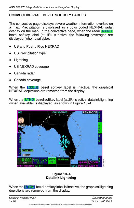
KSN 765/770 Integrated Communication Navigation Display
D200802000009REV 2 Jun 2014
Datalink Weather View10-12
Honeywell International Inc. Do not copy without express permission of Honeywell.
CONVECTIVE PAGE BEZEL SOFTKEY LABELS
The convective page displays severe weather information overlaid ona map. Precipitation is displayed as a color coded NEXRAD radaroverlay on the map. In the convective page, when the radar NXRDbezel softkey label (at 1R) is active, the following coverages aredisplayed (when available):
D US and Puerto Rico NEXRAD
D US Precipitation type
D Lightning
D US NEXRAD coverage
D Canada radar
D Canada coverage.
When the NXRD bezel softkey label is inactive, the graphicalNEXRAD depictions are removed from the display.
When the LTNG bezel softkey label (at 2R) is active, datalink lightning(when available) is displayed, as shown in Figure 10--4.
Figure 10--4Datalink Lightning
When the LTNG bezel softkey label is inactive, the graphical lightningdepictions are removed from the display.

KSN 765/770 Integrated Communication Navigation Display
D200802000009REV 2 Jun 2014 10-13
Datalink Weather View
Honeywell International Inc. Do not copy without express permission of Honeywell.
When the convective SIG bezel softkey label (at 3R) is active, theSIGMETgraphical depictions (whenavailable) are displayed, as shownin Figure 10--5.
Figure 10--5SIGMETs
When the SIG bezel softkey label is inactive, the SIGMET graphicaldepictions are removed from the display.

KSN 765/770 Integrated Communication Navigation Display
D200802000009REV 2 Jun 2014
Datalink Weather View10-14
Honeywell International Inc. Do not copy without express permission of Honeywell.
When the convective INFO bezel softkey label (at 4L) is active,convective graphical depictions are individually selectable andhighlighted, as shown in Figure 10--6. Rotating the joystick knobtoggles through the selectable items depicted on the convective page.The touchscreen display can also be used to select individualconvective displays.
Figure 10--6Convective Info Bezel Softkey Label
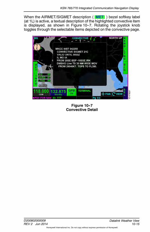
KSN 765/770 Integrated Communication Navigation Display
D200802000009REV 2 Jun 2014 10-15
Datalink Weather View
Honeywell International Inc. Do not copy without express permission of Honeywell.
When the AIRMET/SIGMET description ( MET ) bezel softkey label(at 1L) is active, a textual description of the highlighted convective itemis displayed, as shown in Figure 10--7. Rotating the joystick knobtoggles through the selectable items depicted on the convective page.
Figure 10--7Convective Detail

KSN 765/770 Integrated Communication Navigation Display
D200802000009REV 2 Jun 2014
Datalink Weather View10-16
Honeywell International Inc. Do not copy without express permission of Honeywell.
CONVECTIVE PAGE LEGEND DISPLAY
The convective page legend, shown in Figure 10--8, is displayed whenthe LGND bezel softkey label is inactive. The convective page legendassists the pilot in recognizing the different graphical weatherdepictions.
NOTE: The LGND bezel softkey label is displayedwhen the INFObezel softkey label is inactive. LGND is replacedwith METwhen INFO is active.
Figure 10--8Convective Legend
When the US precipitation type is not available but US NEXRAD radaris available, the graphical weather depiction is displayed as rain.
When the US precipitation type is available and US NEXRAD radar isnot available, the US NEXRAD data is not displayed.
When US coverage is not available or expired and US NEXRAD isavailable, the weather depiction is displayed as if all US radar sites arevalid.
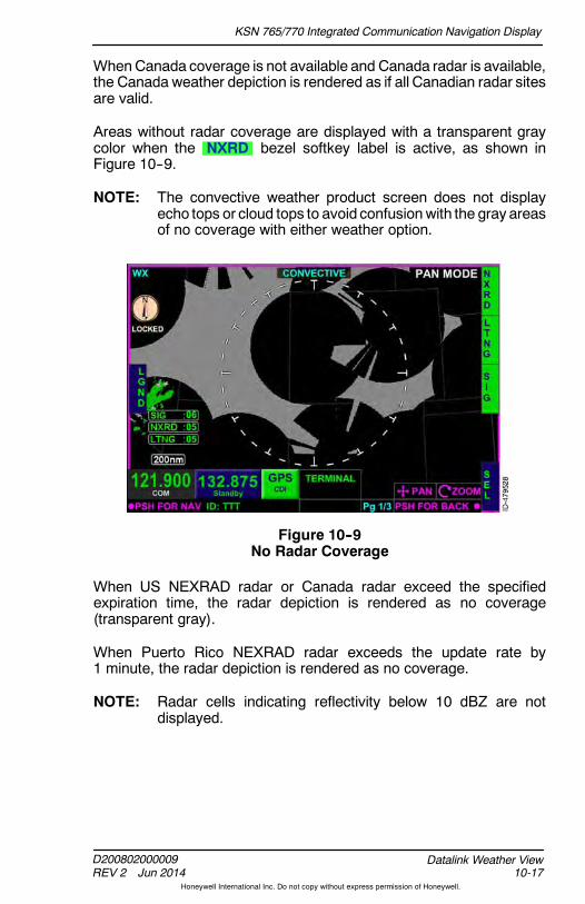
KSN 765/770 Integrated Communication Navigation Display
D200802000009REV 2 Jun 2014 10-17
Datalink Weather View
Honeywell International Inc. Do not copy without express permission of Honeywell.
WhenCanada coverage is not available and Canada radar is available,the Canada weather depiction is rendered as if all Canadian radar sitesare valid.
Areas without radar coverage are displayed with a transparent graycolor when the NXRD bezel softkey label is active, as shown inFigure 10--9.
NOTE: The convective weather product screen does not displayecho tops or cloud tops to avoid confusionwith the gray areasof no coverage with either weather option.
Figure 10--9No Radar Coverage
When US NEXRAD radar or Canada radar exceed the specifiedexpiration time, the radar depiction is rendered as no coverage(transparent gray).
When Puerto Rico NEXRAD radar exceeds the update rate by1 minute, the radar depiction is rendered as no coverage.
NOTE: Radar cells indicating reflectivity below 10 dBZ are notdisplayed.
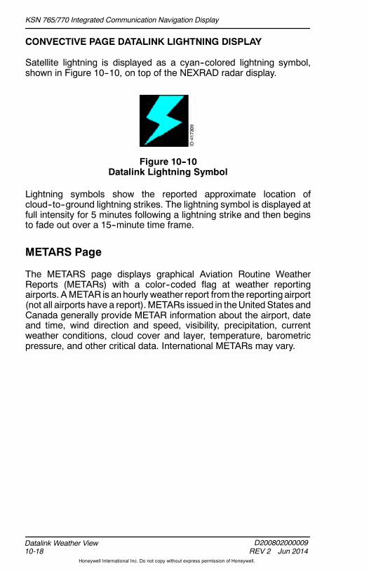
KSN 765/770 Integrated Communication Navigation Display
D200802000009REV 2 Jun 2014
Datalink Weather View10-18
Honeywell International Inc. Do not copy without express permission of Honeywell.
CONVECTIVE PAGE DATALINK LIGHTNING DISPLAY
Satellite lightning is displayed as a cyan--colored lightning symbol,shown in Figure 10--10, on top of the NEXRAD radar display.
Figure 10--10Datalink Lightning Symbol
Lightning symbols show the reported approximate location ofcloud--to--ground lightning strikes. The lightning symbol is displayed atfull intensity for 5 minutes following a lightning strike and then beginsto fade out over a 15--minute time frame.
METARS Page
The METARS page displays graphical Aviation Routine WeatherReports (METARs) with a color--coded flag at weather reportingairports. AMETAR is anhourly weather report from the reporting airport(not all airports have a report). METARs issued in theUnited States andCanada generally provide METAR information about the airport, dateand time, wind direction and speed, visibility, precipitation, currentweather conditions, cloud cover and layer, temperature, barometricpressure, and other critical data. International METARs may vary.

KSN 765/770 Integrated Communication Navigation Display
D200802000009REV 2 Jun 2014 10-19
Datalink Weather View
Honeywell International Inc. Do not copy without express permission of Honeywell.
The METARS page displays graphical METAR data as colored flags,as shown in Figure 10--11. The METARS page displays the flags atairport locations from which the METAR is reported, overlaid on amap.
Figure 10--11METARS Page
METARS DISPLAY
The METARS page legend, shown in Figure 10--12, assists the pilot inrecognizing the different flight conditions reported at the airport. Thegraphically displayed flags are color--coded to indicate the differentflight conditions. When the LGND bezel softkey label is active fordisplay, the METARS legend is displayed.
Figure 10--12METAR Legend
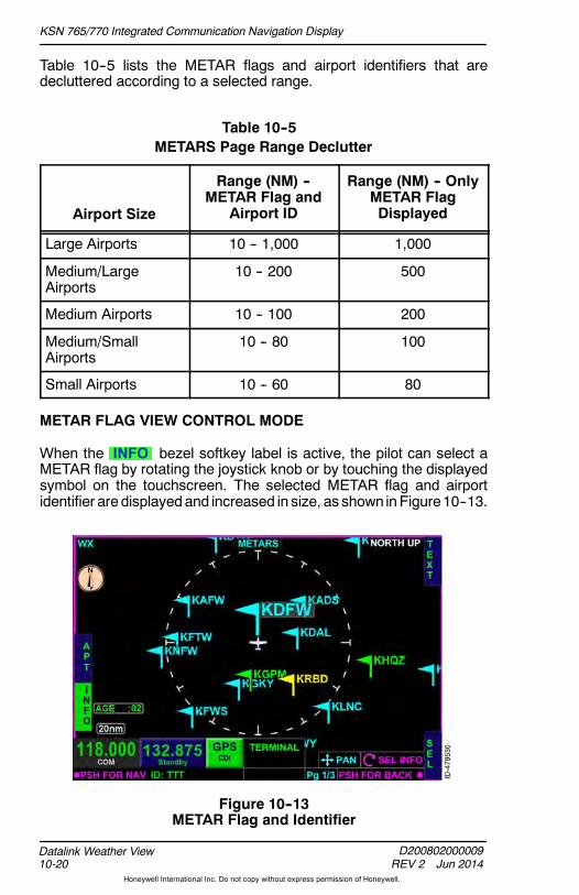
KSN 765/770 Integrated Communication Navigation Display
D200802000009REV 2 Jun 2014
Datalink Weather View10-20
Honeywell International Inc. Do not copy without express permission of Honeywell.
Table 10--5 lists the METAR flags and airport identifiers that aredecluttered according to a selected range.
Table 10--5METARS Page Range Declutter
Airport Size
Range (NM) --METAR Flag and
Airport ID
Range (NM) -- OnlyMETAR FlagDisplayed
Large Airports 10 -- 1,000 1,000
Medium/LargeAirports
10 -- 200 500
Medium Airports 10 -- 100 200
Medium/SmallAirports
10 -- 80 100
Small Airports 10 -- 60 80
METAR FLAG VIEW CONTROL MODE
When the INFO bezel softkey label is active, the pilot can select aMETAR flag by rotating the joystick knob or by touching the displayedsymbol on the touchscreen. The selected METAR flag and airportidentifier are displayedand increased in size, as shown inFigure10--13.
Figure 10--13METAR Flag and Identifier

KSN 765/770 Integrated Communication Navigation Display
D200802000009REV 2 Jun 2014 10-21
Datalink Weather View
Honeywell International Inc. Do not copy without express permission of Honeywell.
Clockwise rotation of the joystick knob selects theMETAR flags in a leftto right, top to bottom order. Counterclockwise rotation of the joystickknob cycles through the METAR flags from right to left, bottom to toporder.
When an airport identifier is selected and the METAR flag is within thevisible areaof the view, theMETAR flag for the selected airport identifieris selected when the select weather depiction view control mode isactive.
When an airport identifier is selected and the METAR flag is not withinthe visible area of the view, theMETAR flagwhich is South of theairportidentifier selected (within the visible area of the view) is selected.
METAR TEXT
When METAR APT bezel softkey label is active, the latest METARtext, previous METAR text, and latest terminal aerodrome forecast(TAF) text are displayed (when available), as shown in Figure 10--14.
Figure 10--14METAR Text

KSN 765/770 Integrated Communication Navigation Display
D200802000009REV 2 Jun 2014
Datalink Weather View10-22
Honeywell International Inc. Do not copy without express permission of Honeywell.
When available, Special Observation and Current Observationare displayed above the special and current observations in cyan.Previous Observation is displayed above the previous METAR text,and Terminal Forecast is displayed above the latest TAF text.
There are two options for viewing textual METARs:
1. Rotating the joystick knob through multiple airports METARs, or
2. Viewingan individual airportMETARbyentering the airport identifierusing the joystick knob to change the airport identifier or by tappingon the airport identifier and entering the desired identifier using theQWERTY keypad.
DEP, DEST, AND NRST BEZEL SOFTKEY LABELS
When the TEXT bezel softkey label is active, DEP , DEST , andNRST bezel softkey labels are displayed along the right side, asshown in Figure 10--15.
Figure 10--15DEP, DEST, and NRST
The following paragraphs describe the DEP, DEST, and NRST bezelsoftkey label functions:
D DEP -- Pushing the DEP bezel softkey automatically fills theidentifier of the airport (with METAR information) closest to thestartup latitude/longitude point. In addition, theSELECTING DEPARTURE message is displayed for 1 second.

KSN 765/770 Integrated Communication Navigation Display
D200802000009REV 2 Jun 2014 10-23
Datalink Weather View
Honeywell International Inc. Do not copy without express permission of Honeywell.
D DEST -- Pushing the DEST bezel softkey automatically fills theidentifier of the airport (with METAR information) closest to thedestination latitude/longitude point or the airport closest to thestartup latitude/longitude point when a destination is not entered inthe flight plan. In addition, the SELECTING DESTINATIONmessage is displayed for 1 second.
D NRST -- Pushing the NRST bezel softkey automatically fills theidentifier of the nearest airport (with METAR information) to theaircraft present position. At startup, this is the same as the DEPbezel softkey. In addition, the SELECTING NEAREST messageis displayed for 1 second.
NOTES: 1. The destination latitude/longitude is basedon the flightplan of the GPS receiver.
2. At start--up the DEP , DEST , and NRST bezelsoftkey labels associated with the METAR weatherview are only displayed when the aircraft positioninformation is available.
3. The DEP , DEST , and NRST bezel softkey labelare removed from display if the aircraft positionbecomes unavailable.
METARs and TAFs for airports other than the departure, destination,and nearest can be viewed by using joystick knob and the touchscreento change the airport identifier as desired, or by tapping on the airportidentifier andentering thedesired identifier using theQWERTYkeypad.

KSN 765/770 Integrated Communication Navigation Display
D200802000009REV 2 Jun 2014
Datalink Weather View10-24
Honeywell International Inc. Do not copy without express permission of Honeywell.
Echo Tops Page
Echo tops data indicates the highest altitude at which precipitation isfalling. The echo tops page is overlaid on a mosaic map display. Echotops indicate the location and altitude (above MSL) of the highest radarecho, as shown in Figure 10--16.
Figure 10--16Echo Tops Page
The echo tops display is similar to cloud tops. However in most casesthe top of the cloud will be somewhat higher than the top of theprecipitation echoes. Echo tops are useful when determining theintensity of a storm’s updraft. Generally the higher the echo tops, thestronger the updraft within a storm,whichmakes convective windgustsand large hail more likely.
The echo tops page displays graphical echo tops information at orabove the selected altitude filter. The pilot can select and increase thealtitude filter by pushing the FL+ bezel softkey.Decreasing thealtitudefilter is accomplished when the pilot pushes the FL-- bezel softkey.The current filter level is displayed in the lower--center of the display.
NOTE: The echo tops altitude filter value moves in increments of5,000 feet. Thealtitude filter canbeadjustedup to 70,000 feetto as lowas 5,000 feet and is retained followingapowercycle.

KSN 765/770 Integrated Communication Navigation Display
D200802000009REV 2 Jun 2014 10-25
Datalink Weather View
Honeywell International Inc. Do not copy without express permission of Honeywell.
Thegraphical echo tops is displayed in 15 shadesof gray,with darkgraydisplayedas the lowest altitude filter, andwhite displayedas thehighestaltitude filter. The echo tops legend, shown in Figure 10--17, isdisplayed when the LGND bezel softkey is pushed.
Figure 10--17Echo Tops Legend

KSN 765/770 Integrated Communication Navigation Display
D200802000009REV 2 Jun 2014
Datalink Weather View10-26
Honeywell International Inc. Do not copy without express permission of Honeywell.
Cloud Tops Page
The cloud tops page displays a cloud top graphical depiction. Cloudtops are the height of convective and upper--level clouds determinedfrom the satellite mosaic. When the datalink weather view cloud topspage is selected, cloud tops are overlaid on a mosaic map, as shownin Figure 10--18.
Figure 10--18Cloud Tops Page
The cloud tops page displays graphical cloud tops information at orabove the selected altitude filter. The pilot can select and increase thealtitude filter by pushing the FL+ bezel softkey.Decreasing thealtitudefilter is accomplished when the pilot pushes the FL-- bezel softkey.The current filter level is displayed in the lower--center of the display andis retained following a power cycle.
NOTE: The cloud tops altitude filter increments basedon thedatalinkdata.

KSN 765/770 Integrated Communication Navigation Display
D200802000009REV 2 Jun 2014 10-27
Datalink Weather View
Honeywell International Inc. Do not copy without express permission of Honeywell.
Thegraphical cloud tops page is displayed in 7 shades of gray, with darkgray displayed as the lowest altitude filter, and white displayed as thehighest altitude filter. The cloud tops legend, shown in Figure 10--19, isdisplayed when the LGND bezel softkey is pushed.
Figure 10--19Cloud Tops Legend

KSN 765/770 Integrated Communication Navigation Display
D200802000009REV 2 Jun 2014
Datalink Weather View10-28
Honeywell International Inc. Do not copy without express permission of Honeywell.
AIRMET/SIGMET Page
TheAIRMET/SIGMET page displays a graphical depiction of AIRMETs(Airmen’s Meteorological information) and SIGMETs (SignificantMeteorological information). AIRMETs and SIGMETs are weatheradvisories broadcast by the National Weather Service for the lower48 contiguous United States and adjacent coastal waters. TheAIRMET/SIGMET page displays advisories as graphical imagesoverlaid on a map, as shown in Figure 10--20.
Figure 10--20AIRMET/SIGMET Page
The following is a description of the bezel softkey labels displayed onthe AIRMET/SIGMET page:
D ICNG -- When the ICNG bezel softkey label is active, icingAIRMETs and SIGMETs (when available) are displayed. When theICNG bezel softkey label is inactive, icing AIRMETs andSIGMETsare removed from the display.
D TURB -- When the TURB bezel softkey label is active, turbulenceAIRMETs and SIGMETs, and surface wind AIRMETs (whenavailable) are displayed. When the TURB bezel softkey label isinactive, turbulence AIRMETs and SIGMETs, and surface windAIRMETs are removed from the display.
D IMC -- When the IMC bezel softkey label is active, IFR AIRMETs,mountain obstruction AIRMETs, dust storm SIGMETs, volcanic ashSIGMETs, and sandstorm SIGMETs (when available) aredisplayed. When the IMC bezel softkey label is inactive,Instrument Meteorological Conditions (IMC) graphical data isremoved from the display.

KSN 765/770 Integrated Communication Navigation Display
D200802000009REV 2 Jun 2014 10-29
Datalink Weather View
Honeywell International Inc. Do not copy without express permission of Honeywell.
D CONV -- When the CONV bezel softkey label is active convectiveSIGMETs (when available) are displayed. When the CONV bezelsoftkey label is inactive, convective SIGMETs are removed from thedisplay.
The AIRMET/SIGMET page legend, shown in Figure 10--21, isdisplayed to assist the pilot in recognizing the different AIRMETs andSIGMETs reported. The graphically displayed AIRMETs and SIGMETsindicate the different conditions. The legend is displayed when theLGND bezel softkey label is active.
Figure 10--21AIRMET/SIGMET Legend

KSN 765/770 Integrated Communication Navigation Display
D200802000009REV 2 Jun 2014
Datalink Weather View10-30
Honeywell International Inc. Do not copy without express permission of Honeywell.
When the INFO bezel softkey label (at 2L) is active, AIRMET andSIGMET graphical depictions are individually selectable andhighlighted, as shown in Figure 10--22. Rotating the joystick knobtoggles through the selectable items depictedon theAIRMET/SIGMETpage. The touchscreen can also be used to select individual AIRMETsand SIGMETs.
Figure 10--22AIRMET/SIGMET Info Bezel Softkey Label

KSN 765/770 Integrated Communication Navigation Display
D200802000009REV 2 Jun 2014 10-31
Datalink Weather View
Honeywell International Inc. Do not copy without express permission of Honeywell.
When the MET bezel softkey label (at 1L) is active, a textualdescription of the highlighted AIRMET or SIGMET is displayed, asshown in Figure 10--23. Rotating the joystick knob toggles through theselectable items depicted on the AIRMET/SIGMET page.
Figure 10--23AIRMET/SIGMET Detail

KSN 765/770 Integrated Communication Navigation Display
D200802000009REV 2 Jun 2014
Datalink Weather View10-32
Honeywell International Inc. Do not copy without express permission of Honeywell.
Temporary Flight Restriction (TFR) Page
The TFR page displays a graphical depiction of temporary flightrestrictions, outlined in redonamosaicmap, as shown inFigure 10--24.TFRs are usually issued in the United States and are typically shortterm. TFRs can include major sporting events, air shows, naturaldisaster areas, space launches, and Presidential movements.
Figure 10--24TFR Page
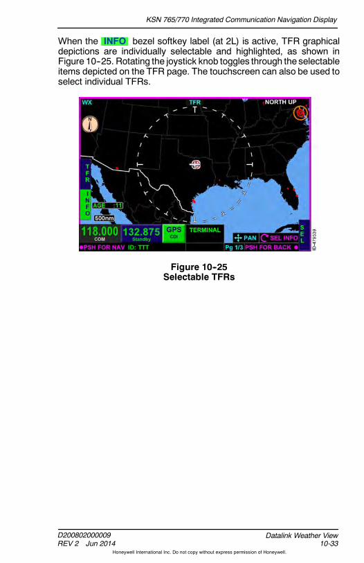
KSN 765/770 Integrated Communication Navigation Display
D200802000009REV 2 Jun 2014 10-33
Datalink Weather View
Honeywell International Inc. Do not copy without express permission of Honeywell.
When the INFO bezel softkey label (at 2L) is active, TFR graphicaldepictions are individually selectable and highlighted, as shown inFigure 10--25. Rotating the joystick knob toggles through the selectableitems depicted on the TFR page. The touchscreen can also be used toselect individual TFRs.
Figure 10--25Selectable TFRs

KSN 765/770 Integrated Communication Navigation Display
D200802000009REV 2 Jun 2014
Datalink Weather View10-34
Honeywell International Inc. Do not copy without express permission of Honeywell.
When the TFR bezel softkey label (at 1L) is active, a textualdescription of the highlighted TFR is displayed, as shown inFigure 10--26. Rotating the joystick knob toggles through the selectableitems depicted on the TFR page. The type of restricted area, the name,the altitudes affected, the date and time the TFR was created andmodified, and the date and time the TFR is active and expires (whenavailable) are displayed.
Figure 10--26TFR Selected
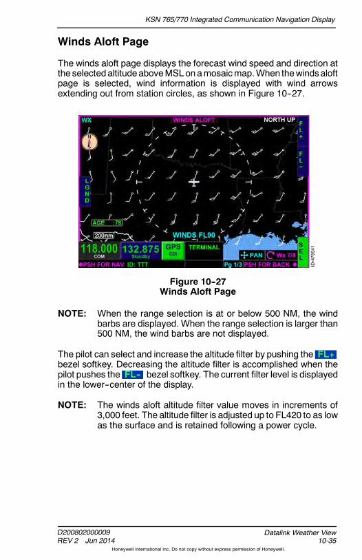
KSN 765/770 Integrated Communication Navigation Display
D200802000009REV 2 Jun 2014 10-35
Datalink Weather View
Honeywell International Inc. Do not copy without express permission of Honeywell.
Winds Aloft Page
The winds aloft page displays the forecast wind speed and direction atthe selectedaltitudeaboveMSLonamosaicmap.When thewindsaloftpage is selected, wind information is displayed with wind arrowsextending out from station circles, as shown in Figure 10--27.
Figure 10--27Winds Aloft Page
NOTE: When the range selection is at or below 500 NM, the windbarbs are displayed. When the range selection is larger than500 NM, the wind barbs are not displayed.
The pilot can select and increase the altitude filter by pushing the FL+bezel softkey. Decreasing the altitude filter is accomplished when thepilot pushes the FL-- bezel softkey. The current filter level is displayedin the lower--center of the display.
NOTE: The winds aloft altitude filter value moves in increments of3,000 feet. The altitude filter is adjusted up to FL420 to as lowas the surface and is retained following a power cycle.
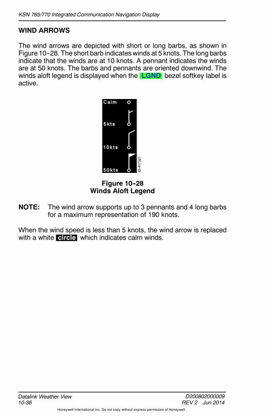
KSN 765/770 Integrated Communication Navigation Display
D200802000009REV 2 Jun 2014
Datalink Weather View10-36
Honeywell International Inc. Do not copy without express permission of Honeywell.
WIND ARROWS
The wind arrows are depicted with short or long barbs, as shown inFigure 10--28. The short barb indicateswinds at 5 knots. The longbarbsindicate that the winds are at 10 knots. A pennant indicates the windsare at 50 knots. The barbs and pennants are oriented downwind. Thewinds aloft legend is displayed when the LGND bezel softkey label isactive.
Figure 10--28Winds Aloft Legend
NOTE: The wind arrow supports up to 3 pennants and 4 long barbsfor a maximum representation of 190 knots.
When the wind speed is less than 5 knots, the wind arrow is replacedwith a white circle which indicates calm winds.

KSN 765/770 Integrated Communication Navigation Display
D200802000009REV 2 Jun 2014 10-37
Datalink Weather View
Honeywell International Inc. Do not copy without express permission of Honeywell.
XM Status Page
When the datalink weather XMstatus page is selected, the XM receiverstatus pop--up box is displayed, as shown in Figure 10--29.
Figure 10--29XM Receiver Status Page
The XM receiver status pop--up box displays the following information:
D XM serial number
NOTE: XM serial number is only displayed when the KSN isconfigured as theController. Consult an avionics installer.
D Signal quality
D Status message
D Control state
D Time
D Descriptive messages.
XM SERIAL NUMBER
The XM serial number is displayed as an 8--digit alphanumeric code.When the serial number is not available, the XM serial number is blank.

KSN 765/770 Integrated Communication Navigation Display
D200802000009REV 2 Jun 2014
Datalink Weather View10-38
Honeywell International Inc. Do not copy without express permission of Honeywell.
SIGNAL QUALITY
Table 10--6 lists the available signal quality annunciators that aredisplayed in the XM receiver status pop--up box.
Table 10--6Signal Quality Annunciators
Annunciator Description
No SignalNo satellite signal is received. This is areception problem, or a broken or missingantenna.
Weak XM receiver is receiving some signal, butthe quality is low, which can prevent the dataproducts from being received and displayed.
Marginal XM receiver is receiving some signal, butthe quality is marginal, which can preventsome of the data products from beingreceived and displayed.
Good The receiver is detecting a normal satellitesignal and data is reliable.
Unknown No signal information is available.

KSN 765/770 Integrated Communication Navigation Display
D200802000009REV 2 Jun 2014 10-39
Datalink Weather View
Honeywell International Inc. Do not copy without express permission of Honeywell.
STATUS MESSAGES
Table 10--7 lists the available status message annunciators that aredisplayed in the XM receiver status pop--up box.
Table 10--7Status Message Annunciators
Annunciator Description
Operational The XM receiver is initialized and ready toreceive data.
Powering Up The XM receiver is in the process ofinitializing. If the receiver does notcommunicate or fails to initialize, the KSN765/770 attempts to power--up again after15 seconds. Continued failure to power--upmeans there is an issue with the power tothe receiver, a bad connection between theKSN 765/770 and receiver, or a badconnection between the KSN 765/770 andthe XM receiver.
Tuning The XM receiver is attempting to locate thesatellite and tune to the correct channel toreceive the weather products. If this statepersists, then it means a broken ordisconnected antenna, or the satellite signalis obstructed.
Saving Config Periodically, the unit configuration is saved(such as subscription data) and reboots.This is done automatically and is synced byXM such that no weather data products arelost during the cycling.
Unknown Error An error is indicated, but the receiver doesnot specify what the error is.
No Service No service is available.
Data Unavailable The receiver is tuned to the satellite, butdata is not available (such as: off the air,weak signal condition, or service is blocked).
XM Error Indicated The XM receiver indicates that there is anerror, but did not specify the source of theerror.

KSN 765/770 Integrated Communication Navigation Display
D200802000009REV 2 Jun 2014
Datalink Weather View10-40
Honeywell International Inc. Do not copy without express permission of Honeywell.
Table 10--7 (cont)Status Message Annunciators
Annunciator Description
Activation Required The XM receiver is indicating that thereceiver is not activated. Follow theinstructions to activate the receiver.
Antenna Failure The XM receiver is reporting that no antennais connected.
No Communications The XM receiver is not communicating withthe KSN 765/770. Continued failure topower--up means there is an issue withpower to the receiver, a bad connectionbetween the KSN 765/770 and receiver, or abad connection between the KSN 765/770and the XM receiver.
No Signal The XM receiver is indicating that no signalis found.
CONTROL STATE
Table 10--8 lists the available control state annunciators that aredisplayed in the XM receiver status pop--up box.
Table 10--8Control State Annunciators
Annunciator Description
Retrying Doing a soft boot of the XM unit by sendinga power--down command and waiting15 seconds.
Powering Up Initializing communications with the XM unit.
Operational Normal operation mode, where any dataproducts received is displayed.

KSN 765/770 Integrated Communication Navigation Display
D200802000009REV 2 Jun 2014 10-41
Datalink Weather View
Honeywell International Inc. Do not copy without express permission of Honeywell.
Table 10--8 (cont)Control State Annunciators
Annunciator Description
Listening Only The KSN 765/770 is in listen--only mode.This means that a different KSN 765/770 iscontrolling the XM receiver, but this unit stilldisplays any weather product that isreceived. Initializing the XM unit andresponding to errors is the responsibility ofthe other KSN 765/770, and this unit is onlypassively listening.
Configuring The XM unit is configured to send certainperiodic messages (such as signal qualityand time).
Tuning Searching for the satellite signal and tuningto the correct frequency for the weatherproducts.
Validating -- x Validating the content channels for theweather products. There are 11 contentchannels that are used for the XM weatherproducts, so each one is individuallyvalidated.
Validating -- Done The validation of the content channels iscomplete.
Saving Config Periodically, the unit configuration is saved(such as subscription data) and reboots.This is done automatically and is synced byXM such that no weather data products arelost during the cycling.
DESCRIPTIVE MESSAGES
The following are two types of descriptive messages that are displayedin the XM receiver status pop--up box:
D Operational
D Error.
Only one descriptive message is displayed at a time, with errormessages taking precedence over operational messages.

KSN 765/770 Integrated Communication Navigation Display
D200802000009REV 2 Jun 2014
Datalink Weather View10-42
Honeywell International Inc. Do not copy without express permission of Honeywell.
Table 10--9 lists the available operational descriptivemessages that aredisplayed in the XM receiver status pop--up box.
Table 10--9Operational Descriptive Messages
Displayed DescriptiveMessage Description
PriorityOrder
The XM receiver is nowoperational, but maytake several minutesbefore data products aredisplayed
This message is displayedwhen the XM receiverbecomes operational afterbeing inoperative.
1
Geographic limitation:XM Weather is notavailable
This message is displayedwhen the XM data is notavailable from the currentlocation.
2
Winds Aloft dataremoved for ranges >500 NM
This message is displayedwhen in the datalinkweather view winds aloftpage and the rangeselection is above500 NM.
3

KSN 765/770 Integrated Communication Navigation Display
D200802000009REV 2 Jun 2014 10-43
Datalink Weather View
Honeywell International Inc. Do not copy without express permission of Honeywell.
Table 10--10 lists the available error descriptive messages that aredisplayed in the XM receiver status pop--up box.
Table 10--10Error Descriptive Messages
Displayed DescriptiveMessage Description
XM receiver is notcommunicating with this KSN7XX, check power andconnections
This message is displayed whenthe XM receiver is notcommunicating with the KSN765/770.
XM receiver is not activated,Call 800.985.9200, or go toxmweather.com to subscribeSignal Quality Good time:##.# minutesActivation requires12 minutes of continual GoodSignal Quality
This message is displayed whenthe XM receiver is not activated.The ##.# is a number in minutesthat represents how long thesignal has been good.
XM Receiver is not receivingsatellite data, Check antennaconnections
This message is displayed whenthe antenna status is notdetected.

KSN 765/770 Integrated Communication Navigation Display
D200802000009REV 2 Jun 2014
Datalink Weather View10-44
Honeywell International Inc. Do not copy without express permission of Honeywell.
XM PRODUCT AGES
The age of each product is displayed as a time annunciation on eachweather page. In addition, the pilot can view a list of each product’s agefrom the XMProduct Ages screen.When the AGE bezel softkey labelin 1R is active, the XM Product Ages (Generated/Received) aredisplayed, as shown in Figure 10--30.
Figure 10--30XM Product Ages
The XM Product Ages page displays the generated and receivedelapsed time of the following weather products in the following order:
D US NEXRAD Data
D US NEXRAD Coverage
D US Precipitation
D Canada RADAR Data
D Canada Coverage
D Puerto Rico NEXRAD
D DataLink Lightning
D METAR Data
D TAF Data
D Echo Tops Data
D Cloud Tops Data
D SIGMET Data

KSN 765/770 Integrated Communication Navigation Display
D200802000009REV 2 Jun 2014 10-45
Datalink Weather View
Honeywell International Inc. Do not copy without express permission of Honeywell.
D AIRMET Data
D TFR Data
D Surface Winds
D Winds Aloft (3K)
D Winds Aloft (6K)
D Winds Aloft (9K)
D Winds Aloft (12K)
D Winds Aloft (15K)
D Winds Aloft (18K)
D Winds Aloft (21K)
D Winds Aloft (24K)
D Winds Aloft (27K)
D Winds Aloft (30K)
D Winds Aloft (33K)
D Winds Aloft (36K)
D Winds Aloft (39K)
D Winds Aloft (42K).
When the AGE bezel softkey label is inactive, the XM Product Agesdisplay is closed.
Pushing the RST bezel softkey sends a reset command to the XMreceiver.

KSN 765/770 Integrated Communication Navigation Display
D200802000009REV 2 Jun 2014
Datalink Weather View10-46
Honeywell International Inc. Do not copy without express permission of Honeywell.
Blank Page

KSN 765/770 Integrated Communication Navigation Display
D200802000009REV 2 Jun 2014 11-1
Weather Radar View
Honeywell International Inc. Do not copy without express permission of Honeywell.
11. Weather Radar View
INTRODUCTION
Airborne weather radar gives a graphical depiction of the strength andtype of precipitation (e.g., rain, snow). An example of external weatherradar data in horizontal profile is shown in Figure 11--1.
Figure 11--1Weather Radar (Horizontal Profile)
The weather radar view is selected by pushing the MFD bezel keythen pushing the VIEW bezel key or rotating the joystick knob untilthe weather radar view is displayed.

KSN 765/770 Integrated Communication Navigation Display
D200802000009REV 2 Jun 2014
Weather Radar View11-2
Honeywell International Inc. Do not copy without express permission of Honeywell.
WEATHER RADAR VIEW OVERVIEW
Weather radar is an optional feature and requires an external radarsensor and optional interface circuit card. The KSN 765/770 supportsthe display and control of the following external weather radar sensors:
D BendixKing RDS 82/84/86
D BendixKing RDS 82VP/84VP/86VP
D BendixKing RDR 2000/2100.
NOTE: For a detailed description of the external weather radarsystem and how to interpret the radar returns, refer to theexternal weather radar user guide.
Table 11--1 lists the external weather radars that the KSN 765/770supports the display and control of the weather radar modes,operations, views, and characteristics that are enabled in the weatherradar configuration module.
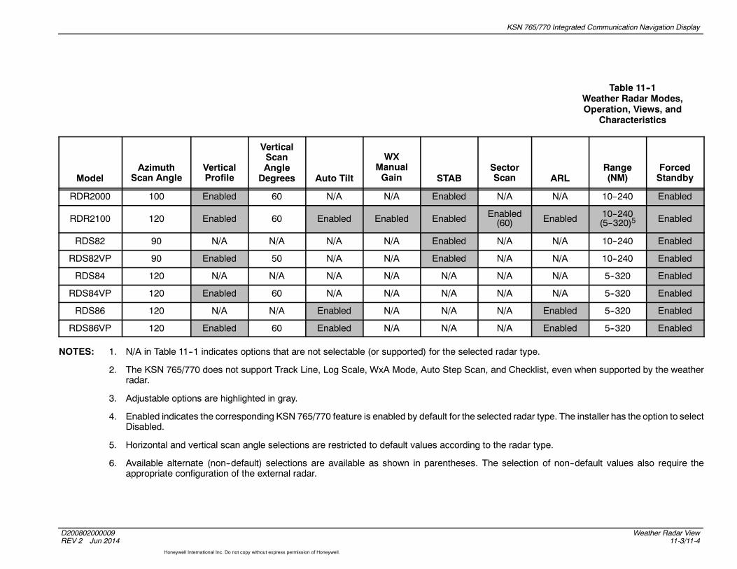
KSN 765/770 Integrated Communication Navigation Display
D200802000009REV 2 Jun 2014
Weather Radar View11-3/11-4
Honeywell International Inc. Do not copy without express permission of Honeywell.
Table 11--1Weather Radar Modes,Operation, Views, and
Characteristics
ModelAzimuth
Scan AngleVerticalProfile
VerticalScanAngleDegrees Auto Tilt
WXManualGain STAB
SectorScan ARL
Range(NM)
ForcedStandby
RDR2000 100 Enabled 60 N/A N/A Enabled N/A N/A 10--240 Enabled
RDR2100 120 Enabled 60 Enabled Enabled Enabled Enabled(60) Enabled 10--240
(5--320)5 Enabled
RDS82 90 N/A N/A N/A N/A Enabled N/A N/A 10--240 Enabled
RDS82VP 90 Enabled 50 N/A N/A Enabled N/A N/A 10--240 Enabled
RDS84 120 N/A N/A N/A N/A N/A N/A N/A 5--320 Enabled
RDS84VP 120 Enabled 60 N/A N/A N/A N/A N/A 5--320 Enabled
RDS86 120 N/A N/A Enabled N/A N/A N/A Enabled 5--320 Enabled
RDS86VP 120 Enabled 60 Enabled N/A N/A N/A Enabled 5--320 Enabled
NOTES: 1. N/A in Table 11--1 indicates options that are not selectable (or supported) for the selected radar type.
2. The KSN 765/770 does not support Track Line, Log Scale, WxA Mode, Auto Step Scan, and Checklist, even when supported by the weatherradar.
3. Adjustable options are highlighted in gray.
4. Enabled indicates the corresponding KSN 765/770 feature is enabled by default for the selected radar type. The installer has the option to selectDisabled.
5. Horizontal and vertical scan angle selections are restricted to default values according to the radar type.
6. Available alternate (non--default) selections are available as shown in parentheses. The selection of non--default values also require theappropriate configuration of the external radar.

KSN 765/770 Integrated Communication Navigation Display
D200802000009REV 2 Jun 2014 11-5
Weather Radar View
Honeywell International Inc. Do not copy without express permission of Honeywell.
Operational Mode Control
The following weather radar operational modes (as applicable to theconfigured installed external weather radar system) are available:
D 1L -- Flight Plan Overlay On/Off ( FPL / FPL ) -- The overlay ofthe flight plan on the weather radar view is permitted during thefollowing conditions:
— Heading is configured and valid— Horizontal profile ( HORZ ) mode is active— FMS/GPS position and track are valid— FMS flight plan is active and available for display— Weather radar view is in Weather, WX/ARL, or GMAP mode— Weather radar is not in forced standby mode.
When the FPL bezel softkey label is active, the flight plansymbols are overlaid on the weather radar view in magneticheading--up orientation. When FPL is inactive, the flight planoverlay function is invalid.
FPL RMVD is displayed in the lower--left corner of the display ifheading or GPS position becomes invalid or a weather radar faultoccurs when the FPL bezel softkey label is active.
D 2L -- Legend ( LGND / LGND ) -- Whenactive, theweather radarlegend is displayed in the upper--left corner of the display.
D 1R -- On/Off ( ON / OFF ) -- Toggles power control to theweatherradar unit on and off. When the ON bezel softkey label is active,the power to the radar unit is turned on and the weather radaroperational and viewmodes are active and selectable. The selectedweather operational mode is displayed in the upper--right corner ofthe display.
When the OFF bezel softkey label is active, the power to the radarunit is turned off and the weather radar operational and viewmodesare removed as well as radar images. OFF is displayed in theupper--right corner of the display when selected off.
The last selection is displayed at power--up. When the weather unitis powered and the ON bezel softkey label is active, the range isset to 80 NM.

KSN 765/770 Integrated Communication Navigation Display
D200802000009REV 2 Jun 2014
Weather Radar View11-6
Honeywell International Inc. Do not copy without express permission of Honeywell.
D 2R -- Operational Mode -- The radar operational mode bezelsoftkey label controls the following weather radar operationalmodes:
Weather Ground Map Standby Test Repeat
Weather ( WX ) -- Fully operation weather mode permitting forweather detection and themodes of operation and optional featuresapplicable to the configured installed external weather radarsystem. WEATHER is displayed in the top--right corner as theoperating mode.
Ground Map Mode ( GMAP ) -- Fully operating ground mappingor map mode to enhance returns from ground targets. In groundmap mode, the Gain is switched from Auto to Manual and can bemanually adjusted by the pilot. GROUND MAP is displayed in thetop--right corner as the operating mode.
Standby ( STBY ) -- When STBY is selected, the weather radarsensor is ready for operation with TX off. Weather radar images areremoved from display. STANDBY is displayed in the top--rightcorner as the operating mode.
Test ( TEST ) -- Activates a limited functional test of the externalweather radar sensor. TEST is displayed in the top--right corner asthe operating mode. The text pattern is shown in Figure 11--2.
Figure 11--2Weather Radar Test Pattern
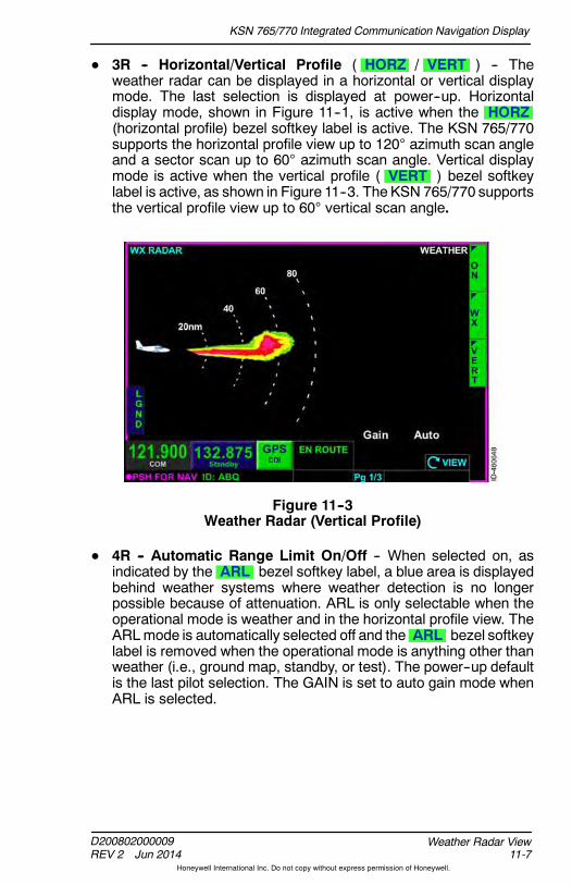
KSN 765/770 Integrated Communication Navigation Display
D200802000009REV 2 Jun 2014 11-7
Weather Radar View
Honeywell International Inc. Do not copy without express permission of Honeywell.
D 3R -- Horizontal/Vertical Profile ( HORZ / VERT ) -- Theweather radar can be displayed in a horizontal or vertical displaymode. The last selection is displayed at power--up. Horizontaldisplay mode, shown in Figure 11--1, is active when the HORZ(horizontal profile) bezel softkey label is active. The KSN 765/770supports the horizontal profile view up to 120 azimuth scan angleand a sector scan up to 60 azimuth scan angle. Vertical displaymode is active when the vertical profile ( VERT ) bezel softkeylabel is active, as shown in Figure 11--3. The KSN 765/770 supportsthe vertical profile view up to 60 vertical scan angle.
Figure 11--3Weather Radar (Vertical Profile)
D 4R -- Automatic Range Limit On/Off -- When selected on, asindicated by the ARL bezel softkey label, a blue area is displayedbehind weather systems where weather detection is no longerpossible because of attenuation. ARL is only selectable when theoperational mode is weather and in the horizontal profile view. TheARLmode is automatically selected off and the ARL bezel softkeylabel is removed when the operational mode is anything other thanweather (i.e., ground map, standby, or test). The power--up defaultis the last pilot selection. The GAIN is set to auto gain mode whenARL is selected.
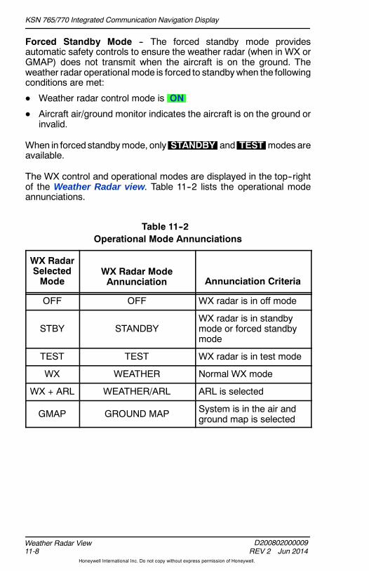
KSN 765/770 Integrated Communication Navigation Display
D200802000009REV 2 Jun 2014
Weather Radar View11-8
Honeywell International Inc. Do not copy without express permission of Honeywell.
Forced Standby Mode -- The forced standby mode providesautomatic safety controls to ensure the weather radar (when in WX orGMAP) does not transmit when the aircraft is on the ground. Theweather radar operational mode is forced to standbywhen the followingconditions are met:
D Weather radar control mode is ON
D Aircraft air/ground monitor indicates the aircraft is on the ground orinvalid.
When in forced standbymode, only STANDBY and TEST modes areavailable.
The WX control and operational modes are displayed in the top--rightof the Weather Radar view. Table 11--2 lists the operational modeannunciations.
Table 11--2Operational Mode Annunciations
WX RadarSelectedMode
WX Radar ModeAnnunciation Annunciation Criteria
OFF OFF WX radar is in off mode
STBY STANDBYWX radar is in standbymode or forced standbymode
TEST TEST WX radar is in test mode
WX WEATHER Normal WX mode
WX + ARL WEATHER/ARL ARL is selected
GMAP GROUND MAP System is in the air andground map is selected
KSN 765/770 Integrated Communication Navigation Display
D200802000009REV 2 Jun 2014 11-9
Weather Radar View
Honeywell International Inc. Do not copy without express permission of Honeywell.
The weather radar feature SET bezel softkey label is displayed in 5Rwhen the weather radar is powered ON , the operational mode is notSTANDBY , and the HORZ view is active. When the weather radarfeature SET bezel softkey label in 5R is active, the followingpilot--selectable weather settings are configurable:
D Stabilization ON/OFF -- When the weather radar is in weathermode (weather or ground map), the system uses pitch and roll tostabilize theantenna.When the STAB bezel softkey label isactive,STAB ON is displayed in the lower--left corner of the display.Whenthe STAB bezel softkey label is inactive, STAB OFF is displayedin the lower--left corner of the display. The power--up default is thelast pilot selection.
NOTE: When configured to use an RDS84/84VP/86/86VPweather radar, the KSN 765/770 does not support theStab On/Off control. However, the KSN 765/770 displaysthe receivedStab statusmessage from theweather radar.
If the commanded stabilization mode is not active while in weather,ground map, or weather/ARL mode, STAB FAULT is displayed inamber.
D Scan Sector ON/OFF -- When active in the horizontal profile view,the total scanned area is cut in half, which provides faster updatesto the remaining area. When the SECT bezel softkey label isactive, SECT 60 is displayed in the lower--left corner of thedisplay. When the SECT bezel softkey label is inactive,SECT 60 is removed from the display. Sector scan can be activein weather, ground map, or weather/ARL mode. The power--updefault is the last pilot selection.
NOTE: Sector scan is only functional in thehorizontal profile view.
If the commanded scan sector mode is not active while in weather,ground map, or weather/ARL mode, STAB FAULT is displayed.
The sector scan angle is limited to the full horizontal scan limitsminus half the sector scan angle applicable to the configuredinstalled external weather radar system. For example, a 120azimuth scan angle is displayed for RDR2100 installations whensector scan is not active (60 either side of center). When sectorscan is active, a 60 azimuth scan angle is displayed (30 either sideof center).
Sector scan control is removed when not applicable to theconfigured installed external weather radar system.

KSN 765/770 Integrated Communication Navigation Display
D200802000009REV 2 Jun 2014
Weather Radar View11-10
Honeywell International Inc. Do not copy without express permission of Honeywell.
D Tilt -- Controls the tilt auto/manual selection to the external weatherradar system. The power--up default is the last pilot selection. Tiltcontrol mode is active while in weather, ground map, test orweather/ARL mode.
Auto tilt mode is selectedwhen the AUTO bezelsoftkey label is active. The tiltannunciation field displaysTilt Auto . Auto tilt permitsthe antenna position to beautomatically adjusted tomaintain a common beamintercept point with the earth.For example, if the last 10%of the display is ground
returns, then during ascent or descent, the antenna automaticallychanges to maintain ground returns on 10% of the display.
Manual tilt is selected byactivating the MAN bezelsoftkey label. The default tiltvalue is the last commandedmanual tilt value and isdisplayed in the manual tiltfield. Manual tilt mode has arange of 15.0. --15.0represents the extremecounterclockwise rotationand +15.0 represents the
extreme clockwise rotation. The tilt display value can be adjustedin 0.25--degree increments using the joystick knob.
When the MAN bezel softkey label is active, the tilt annunciationfield displays TILT followed by the digital readout and Down fornegative values or Up for positive values.
D Gain -- Manual gain is supported in ground map mode and isoptionally supported in weather mode depending on weather radarinstallation.

KSN 765/770 Integrated Communication Navigation Display
D200802000009REV 2 Jun 2014 11-11
Weather Radar View
Honeywell International Inc. Do not copy without express permission of Honeywell.
Weather Radar Range Selection
The weather radar view has a minimum range marker, a maximumrange marker, and two other incremental range markers in both thehorizontal and vertical profile views. Figure 11--3 shows the rangemarkers as 20 , 40 , 60 , and 80 .
The KSN 765/770 supports a pilot--selectable range from 5 or10 NM to240 or 320 NM, as applicable to the configured installed externalweather radar system. The rangeof theweather radar view is controlledby the zoom- in/+ and zoom- out/- bezel keys.
Table 11--3 lists the ranges that are selectable for both horizontal andvertical profile views.
Table 11--3Weather Radar Ranges
Weather Radar Range (NM) Settings
RangeSetting
Min.RangeMarker
RangeMarker(R1)
RangerMarker(R2)
Max.RangeMarker
1* 1 2 3 5
2 2 5 7 10
3 5 10 15 20
4 10 20 30 40
5 20 40 60 80
6 40 80 120 160
7 60 120 180 240
8* 80 160 240 320
* Range settings only applicable when configured and supportedby external weather radar system.

KSN 765/770 Integrated Communication Navigation Display
D200802000009REV 2 Jun 2014
Weather Radar View11-12
Honeywell International Inc. Do not copy without express permission of Honeywell.
Weather Radar Alert Mode
When active by the WX configuration (during weather radarinstallation), the KSN 765/770 can provide a target alert annunciationduring horizontal scan when the weather mode is WX.
NOTES: 1. A target alert is not provided during vertical scan.
2. Target alert is only applicable for RDR 2000 andRDR 2100 installations.
Target alert is a feature that provides warning of potential severeweather in the flight path that is detected beyond the current rangedisplayed.
The criteria for a target alert is for the cell to be at least red intensity,within10_ of aircraft heading, a minimum size of 2 NM in range and2 degrees in azimuth, and within the range of 80 to 320 NM. When atarget alert is issued, two red arcs, separated by a black arc will bedisplayed at the top of the display centered on the aircraft heading.
Target Alert is applied to each scan independent of the other when theradar is alternating scans.
When an alert condition exists, two red arcs separated by a black arcare displayed at the top of the display centered on the aircraft heading,as shown in Figure 11--4.
Figure 11--4Target Alert
When GMAP mode is selected, the target alert function is inactive.
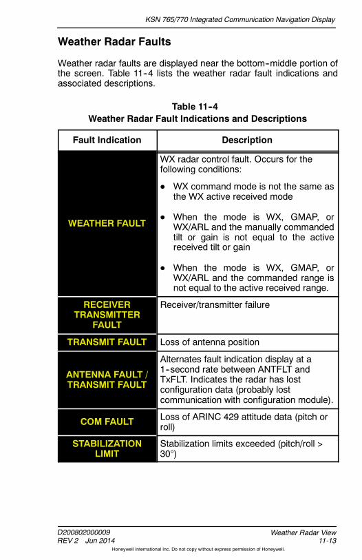
KSN 765/770 Integrated Communication Navigation Display
D200802000009REV 2 Jun 2014 11-13
Weather Radar View
Honeywell International Inc. Do not copy without express permission of Honeywell.
Weather Radar Faults
Weather radar faults are displayed near the bottom--middle portion ofthe screen. Table 11--4 lists the weather radar fault indications andassociated descriptions.
Table 11--4Weather Radar Fault Indications and Descriptions
Fault Indication Description
WEATHER FAULT
WX radar control fault. Occurs for thefollowing conditions:
D WX command mode is not the same asthe WX active received mode
D When the mode is WX, GMAP, orWX/ARL and the manually commandedtilt or gain is not equal to the activereceived tilt or gain
D When the mode is WX, GMAP, orWX/ARL and the commanded range isnot equal to the active received range.
RECEIVERTRANSMITTER
FAULT
Receiver/transmitter failure
TRANSMIT FAULT Loss of antenna position
ANTENNA FAULT /TRANSMIT FAULT
Alternates fault indication display at a1--second rate between ANTFLT andTxFLT. Indicates the radar has lostconfiguration data (probably lostcommunication with configuration module).
COM FAULT Loss of ARINC 429 attitude data (pitch orroll)
STABILIZATIONLIMIT
Stabilization limits exceeded (pitch/roll >30)

KSN 765/770 Integrated Communication Navigation Display
D200802000009REV 2 Jun 2014
Weather Radar View11-14
Honeywell International Inc. Do not copy without express permission of Honeywell.
If a weather radar fault occurs when a flight plan overlay is displayed,the flight plan overlay is removed and FPL RMVD is displayed in thelower--left corner of the display.
NO DATA RECEIVED FROM WEATHER RADAR is displayedwhenany weather radar mode except OFF is selected and the weatherradar picture bus is disconnected.
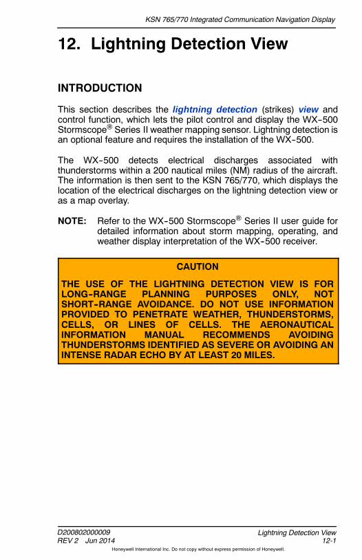
KSN 765/770 Integrated Communication Navigation Display
D200802000009REV 2 Jun 2014 12-1
Lightning Detection View
Honeywell International Inc. Do not copy without express permission of Honeywell.
12. Lightning Detection View
INTRODUCTION
This section describes the lightning detection (strikes) view andcontrol function, which lets the pilot control and display the WX--500Stormscope Series II weather mapping sensor. Lightning detection isan optional feature and requires the installation of the WX--500.
The WX--500 detects electrical discharges associated withthunderstorms within a 200 nautical miles (NM) radius of the aircraft.The information is then sent to the KSN 765/770, which displays thelocation of the electrical discharges on the lightning detection view oras a map overlay.
NOTE: Refer to the WX--500 Stormscope Series II user guide fordetailed information about storm mapping, operating, andweather display interpretation of the WX--500 receiver.
CAUTION
THE USE OF THE LIGHTNING DETECTION VIEW IS FORLONG--RANGE PLANNING PURPOSES ONLY, NOTSHORT--RANGE AVOIDANCE. DO NOT USE INFORMATIONPROVIDED TO PENETRATE WEATHER, THUNDERSTORMS,CELLS, OR LINES OF CELLS. THE AERONAUTICALINFORMATION MANUAL RECOMMENDS AVOIDINGTHUNDERSTORMS IDENTIFIED AS SEVERE OR AVOIDING ANINTENSE RADAR ECHO BY AT LEAST 20 MILES.

KSN 765/770 Integrated Communication Navigation Display
D200802000009REV 2 Jun 2014
Lightning Detection View12-2
Honeywell International Inc. Do not copy without express permission of Honeywell.
STRIKES OVERVIEW
The strikes view is selected by pushing the MFD bezel key thenpushing the VIEW bezel key or rotating the joystick knob until theSTRIKES view, shown in Figure 12--1, is displayed.
NOTE: When an active flight plan is available, the flight plan isoverlaid on the lightning detection view.
Figure 12--1STRIKES View
Strikes View Modes
The pilot can select between the 360 compass view mode and the arcview mode.
The 360 compass view mode is displayed when the 360 bezelsoftkey label is active. When the 360 compassmode is displayed, thecurrent aircraft symbol is located in the center of the strikes view, asshown in Figure 12--1.

KSN 765/770 Integrated Communication Navigation Display
D200802000009REV 2 Jun 2014 12-3
Lightning Detection View
Honeywell International Inc. Do not copy without express permission of Honeywell.
The arc view mode is displayed when the ARC bezel softkey label isactive. When the arc mode is displayed, the current aircraft symbol islocated in the bottom of the strikes view, as shown in Figure 12--2.
Figure 12--2Strikes View -- Arc
The strikes view scale is controlled using the zoom- in/+ andzoom- out/- bezel keys, such that the outer radius of the primaryrange ring represents 20 , 30 , 40 , 60 , 80 , 100 , and200 NM from the current aircraft position. The last setting selected isstored following the power cycle of the unit.
Strikes Display Modes
The pilot can select two strike display modes by enabling either of thefollowing bezel softkey labels in 2R:
D STRK -- Activates strike mode
D CELL -- Activates cell mode.
The display mode is indicated in the upper--right corner of the strikesview (i.e., CELL or STRIKE ), as shown in Figure 12--2.
NOTE: The display mode annunciation is removed from displaywhen the FAIL NO LINK annunciation is displayed.
When strike mode is active, the displayed symbols are actual strikes.When cell mode is active, the displayed symbols are cells, which area combination of strikes.

KSN 765/770 Integrated Communication Navigation Display
D200802000009REV 2 Jun 2014
Lightning Detection View12-4
Honeywell International Inc. Do not copy without express permission of Honeywell.
Strike mode symbols are displayed as an amber x and cell modesymbols are displayed as an amber + . Both symbols are removedfrom the display after 3 minutes, and recent strikes overlay olderstrikes.
Strikes Sensor Status
When the Stormscope is not in self--test mode, the rate annunciator( +RATE # or xRATE # ), located in the lower--right corner of theview, displays the mode symbol and current strike rate. Figure 12--3shows the strike mode rate annunciation. Figure 12--4 shows the cellmode rate annunciation.
NOTE: Pushing the CLR bezel softkey in 3R resets the rate to 0.
Figure 12--3Strike Mode Rate Annunciator
Figure 12--4Cell Mode Rate Annunciator
When theStormscope is in self--testmode, STKS TEST is displayedin place of the rate annunciation.
Lightning symbols are removed and xRMVD or+RMVD replaces the rate annunciator in thelower--right corner when the range is less than
20 NM. Lightning data is not displayed if aircraft heading information isnot available.

KSN 765/770 Integrated Communication Navigation Display
D200802000009REV 2 Jun 2014 12-5
Lightning Detection View
Honeywell International Inc. Do not copy without express permission of Honeywell.
Error Annunciators
Lightning symbols are removed from displayand a red horizontal line is displayed through thestrike or cell mode rate annunciator when any ofthe following conditions occur:
D The Stormscope receiver reports a fault or error
D The heading is invalid or unavailable
D Lightning data is not detected
D Position invalid (only removed from NAV MAP view).
Table 12--1 lists the possible annunciators and conditions that aredisplayed in themiddle of theSTRIKESviewwhenoneof the conditionsare met.
Table 12--1Lightning Annunciators
Annunciator Condition
TEST INIT Displayed when sensor is inself--test mode.
TEST INIT FAIL Displayed when a self--test reportis not received within 10 seconds.
FAIL The sensor status is an undefinedor fatal fault.
ERROR The sensor status is an undefinedrecoverable error.
ERROR ANT ERR The sensor status is a recoverableantenna error.
ERROR MIC INHIBIT STUCK The sensor status is a recoverableinhibit line stuck error.
ERROR ANT JMP CHG The sensor status is a recoverableantenna jumper changed error.
FAIL HDG INVALID Heading is invalid, not available,or not configured.
FAIL NO LINK When configured and data is notdetected.

KSN 765/770 Integrated Communication Navigation Display
D200802000009REV 2 Jun 2014
Lightning Detection View12-6
Honeywell International Inc. Do not copy without express permission of Honeywell.
Blank Page

KSN 765/770 Integrated Communication Navigation Display
D200802000009REV 2 Jun 2014 13-1
Terrain Awareness and Warning System (TAWS) View
Honeywell International Inc. Do not copy without express permission of Honeywell.
13. Terrain Awareness andWarning System (TAWS) View
INTRODUCTION
TheTAWS view displays enhanced ground proximity warning systems(EGPWS) displays. EGPWS gives terrain display, situationalawareness, terrain alerting and warning, and obstacle alerting andwarning to the pilot. It is intended to give advanced alerting andwarningto the pilot to help reduce the possibility of controlled flight into terrain(CFIT).
NOTE: This section does not supersede FAA--approved data, FAAflight manual supplements, or FAA required procedures. Inaddition, this guide is not intended to give all the details ofproper usage and interpretation of EGPWS information.Reference the pilot’s guide that is given with the EGPWSsensor for more information.
TAWS OVERVIEW
The TAWS view is different from the terrain view as the TAWS viewuses an external TAWS sensor and the terrain view uses an internalterrain database. TAWS is an optional feature and requires an externalTAWS sensor and optional interface circuit card. The KSN 765/770supports the display and control of the following external TAWSsensors:
D BendixKing KGP 560/860 General Aviation EGPWS
D BendixKing KMH 880/980 Multi--Hazard Awareness System
D Honeywell MK--VI/MK--VIII EGPWS.
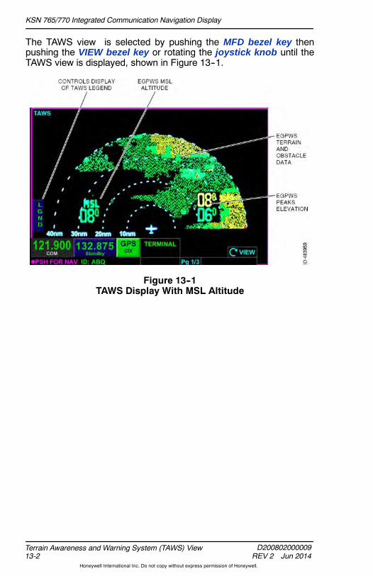
KSN 765/770 Integrated Communication Navigation Display
D200802000009REV 2 Jun 2014
Terrain Awareness and Warning System (TAWS) View13-2
Honeywell International Inc. Do not copy without express permission of Honeywell.
The TAWS view is selected by pushing the MFD bezel key thenpushing the VIEW bezel key or rotating the joystick knob until theTAWS view is displayed, shown in Figure 13--1.
Figure 13--1TAWS Display With MSL Altitude
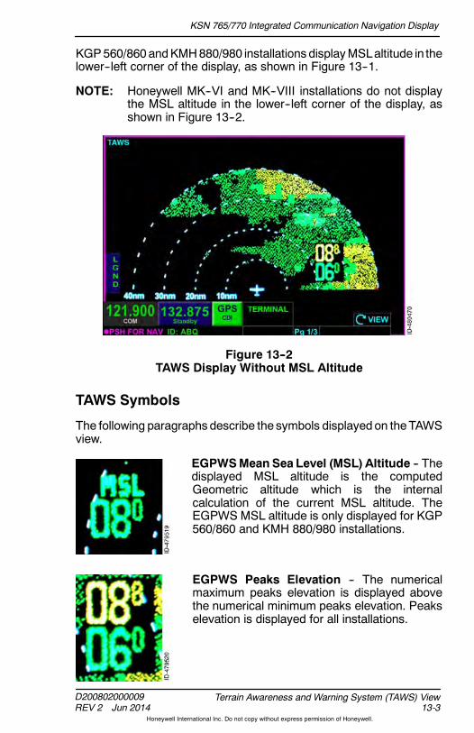
KSN 765/770 Integrated Communication Navigation Display
D200802000009REV 2 Jun 2014 13-3
Terrain Awareness and Warning System (TAWS) View
Honeywell International Inc. Do not copy without express permission of Honeywell.
KGP560/860andKMH880/980 installations displayMSLaltitude in thelower--left corner of the display, as shown in Figure 13--1.
NOTE: Honeywell MK--VI and MK--VIII installations do not displaythe MSL altitude in the lower--left corner of the display, asshown in Figure 13--2.
Figure 13--2TAWS Display Without MSL Altitude
TAWS Symbols
The following paragraphs describe the symbols displayedon theTAWSview.
EGPWSMean Sea Level (MSL) Altitude -- Thedisplayed MSL altitude is the computedGeometric altitude which is the internalcalculation of the current MSL altitude. TheEGPWS MSL altitude is only displayed for KGP560/860 and KMH 880/980 installations.
EGPWS Peaks Elevation -- The numericalmaximum peaks elevation is displayed abovethe numerical minimum peaks elevation. Peakselevation is displayed for all installations.

KSN 765/770 Integrated Communication Navigation Display
D200802000009REV 2 Jun 2014
Terrain Awareness and Warning System (TAWS) View13-4
Honeywell International Inc. Do not copy without express permission of Honeywell.
Display Orientation
HoneywellMK--VI andMK--VIII installations require aheading input anddisplay the TAWS view in heading--up mode.
KGP 560/860 and KMH 880/980 installations do not require a headinginput. When a heading input is available (as determined at the time ofinstallation), the TAWS view is displayed in heading--up mode.
When a heading input in not available for KGP 560/860 andKMH 880/980 installations while in the air, TAWS images are displayedwith an orientation indicator displayed on the top of the view. Theorientation indicator is displayed as MAGXXXTRK, as shown inFigure 13--3.
Figure 13--3No Heading Input Installations -- In Air

KSN 765/770 Integrated Communication Navigation Display
D200802000009REV 2 Jun 2014 13-5
Terrain Awareness and Warning System (TAWS) View
Honeywell International Inc. Do not copy without express permission of Honeywell.
When a heading input is not available for KGP 560/860 andKMH 880/980 installations while on the ground, the TAWS images aredisplayed along with NORTH at the top of the view, as shown inFigure 13--4.
Figure 13--4No Heading Input Installations -- On Ground
Failure Annunciations
If there is a loss of EGPWS data, an amber NO DATA RECEIVEDFROM TAWS annunciator is displayed, as shown in Figure 13--5.
Figure 13--5No Data From TAWS
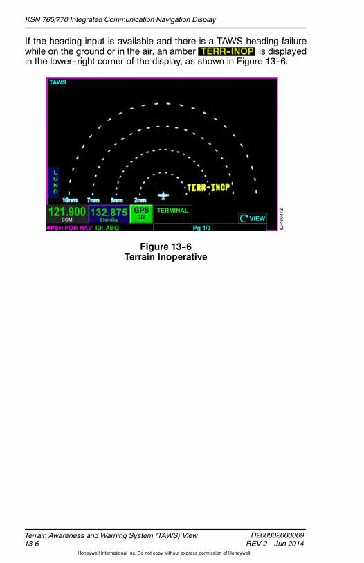
KSN 765/770 Integrated Communication Navigation Display
D200802000009REV 2 Jun 2014
Terrain Awareness and Warning System (TAWS) View13-6
Honeywell International Inc. Do not copy without express permission of Honeywell.
If the heading input is available and there is a TAWS heading failurewhile on the ground or in the air, an amber TERR--INOP is displayedin the lower--right corner of the display, as shown in Figure 13--6.
Figure 13--6Terrain Inoperative
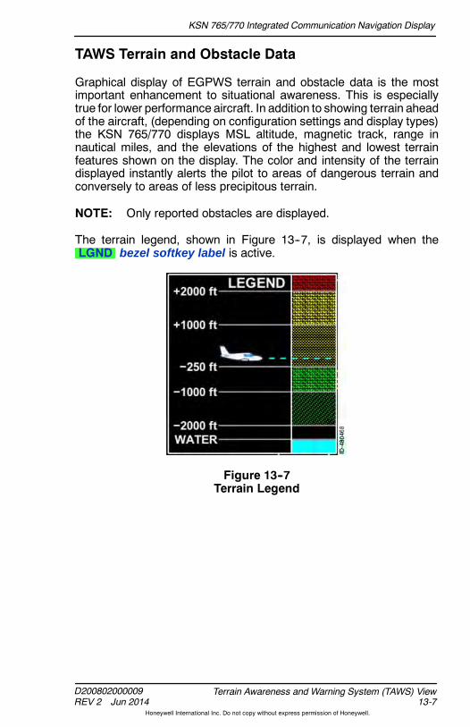
KSN 765/770 Integrated Communication Navigation Display
D200802000009REV 2 Jun 2014 13-7
Terrain Awareness and Warning System (TAWS) View
Honeywell International Inc. Do not copy without express permission of Honeywell.
TAWS Terrain and Obstacle Data
Graphical display of EGPWS terrain and obstacle data is the mostimportant enhancement to situational awareness. This is especiallytrue for lower performance aircraft. In addition to showing terrain aheadof the aircraft, (depending on configuration settings and display types)the KSN 765/770 displays MSL altitude, magnetic track, range innautical miles, and the elevations of the highest and lowest terrainfeatures shown on the display. The color and intensity of the terraindisplayed instantly alerts the pilot to areas of dangerous terrain andconversely to areas of less precipitous terrain.
NOTE: Only reported obstacles are displayed.
The terrain legend, shown in Figure 13--7, is displayed when theLGND bezel softkey label is active.
Figure 13--7Terrain Legend
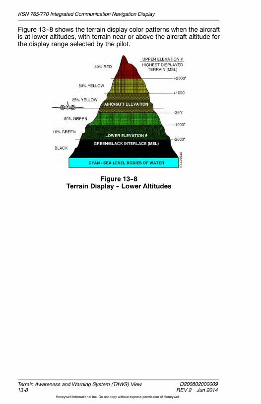
KSN 765/770 Integrated Communication Navigation Display
D200802000009REV 2 Jun 2014
Terrain Awareness and Warning System (TAWS) View13-8
Honeywell International Inc. Do not copy without express permission of Honeywell.
Figure 13--8 shows the terrain display color patterns when the aircraftis at lower altitudes, with terrain near or above the aircraft altitude forthe display range selected by the pilot.
Figure 13--8Terrain Display -- Lower Altitudes
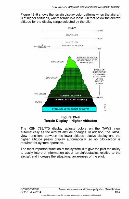
KSN 765/770 Integrated Communication Navigation Display
D200802000009REV 2 Jun 2014 13-9
Terrain Awareness and Warning System (TAWS) View
Honeywell International Inc. Do not copy without express permission of Honeywell.
Figure 13--9 shows the terrain display color patterns when the aircraftis at higher altitudes, where terrain is a least 250 feet below the aircraftaltitude for the display range selected by the pilot.
Figure 13--9Terrain Display -- Higher Altitudes
The KSN 765/770 display adjusts colors on the TAWS viewautomatically as the aircraft altitude changes. In addition, the TAWSview transitions between the lower altitude relative display and thehigher altitude peaks display automatically, so no pilot--action isrequired for system operation.
The most important function of the system is to give the pilot the abilityto easily interpret information about terrain/obstacles relative to theaircraft and increase the situational awareness of the pilot.

KSN 765/770 Integrated Communication Navigation Display
D200802000009REV 2 Jun 2014
Terrain Awareness and Warning System (TAWS) View13-10
Honeywell International Inc. Do not copy without express permission of Honeywell.
Table 13--1 lists the colors displayed on the terrain display withdescriptions.
Table 13--1Terrain Display Colors and Descriptions
Color Description
BLACK No significant terrain/obstacle.
CYAN Sea level bodies of water.
GREENTerrain/obstacles are below the aircraftaltitude. Safe terrain/obstacle clearance isindicated.
YELLOWTerrain is very near or above the aircraftaltitude. THE TERRAIN DOES NOTHAVE SAFE TERRAIN CLEARANCE.
RED
Terrain is at least 2,000 feet higher abovethe aircraft. THE AIRCRAFT DOES NOTHAVE SAFE TERRAIN CLEARANCE.THE AIRCRAFT MAY NOT BE ABLE TOAVOID THIS TERRAIN.
MAGENTA Unknown terrain. No terrain data in thedatabase for the magenta areas shown.
NOTE: Green colors indicating terrain/obstacles below the aircraftare not displayedwhen theaircraft is on theground, to reducedisplay clutter and to show only terrain that is significantlyhigher than the aircraft in the departure area. Green colorsare displayed when the aircraft climbs approximately 500 to800 feet above the elevation of the runway.
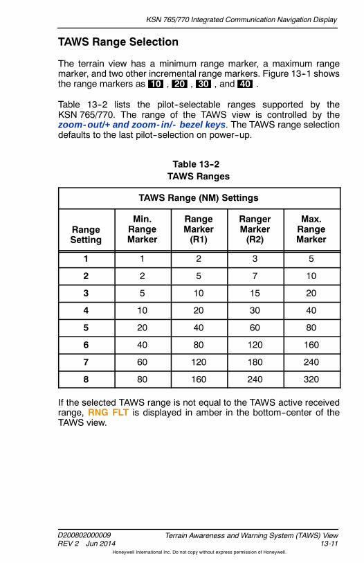
KSN 765/770 Integrated Communication Navigation Display
D200802000009REV 2 Jun 2014 13-11
Terrain Awareness and Warning System (TAWS) View
Honeywell International Inc. Do not copy without express permission of Honeywell.
TAWS Range Selection
The terrain view has a minimum range marker, a maximum rangemarker, and two other incremental range markers. Figure 13--1 showsthe range markers as 10 , 20 , 30 , and 40 .
Table 13--2 lists the pilot--selectable ranges supported by theKSN 765/770. The range of the TAWS view is controlled by thezoom- out/+ and zoom- in/- bezel keys. The TAWS range selectiondefaults to the last pilot--selection on power--up.
Table 13--2TAWS Ranges
TAWS Range (NM) Settings
RangeSetting
Min.RangeMarker
RangeMarker(R1)
RangerMarker(R2)
Max.RangeMarker
1 1 2 3 5
2 2 5 7 10
3 5 10 15 20
4 10 20 30 40
5 20 40 60 80
6 40 80 120 160
7 60 120 180 240
8 80 160 240 320
If the selected TAWS range is not equal to the TAWS active receivedrange, RNG FLT is displayed in amber in the bottom--center of theTAWS view.

KSN 765/770 Integrated Communication Navigation Display
D200802000009REV 2 Jun 2014
Terrain Awareness and Warning System (TAWS) View13-12
Honeywell International Inc. Do not copy without express permission of Honeywell.
TAWS Pop--Up Mode
When a TAWS warning occurs, a redWARNING TERRAIN, TERRAIN annunciator is displayed in the textdata bar and PUSH CLR MSGS is displayed in the lower--right corner,as shown in Figure 13--10.
NOTE: When the TAWS warning or caution is no longer valid, theannunciators are removed from the display.
Figure 13--10TAWS Alert When Not in TAWS View
When a TAWS caution occurs, an amberCAUTION TERRAIN, CAUTION TERRAIN annunciator is displayedin the text data bar and PUSH CLR MSGS is displayed in thelower--right corner.
The TAWS view can be displayed by normal procedures to change thedisplayed view. When the TAWS view is selected for display while orafter a TAWSwarning or caution is active, the range defaults to 10NM.
NOTE: If a TAWSalert occurs when themenu is displayed, themenuoverlay is removed.

KSN 765/770 Integrated Communication Navigation Display
D200802000009REV 2 Jun 2014 14-1
Course Deviation Indicator (CDI) and Switching View
Honeywell International Inc. Do not copy without express permission of Honeywell.
14. Course Deviation Indicator(CDI) and Switching View
INTRODUCTION
This section describes the GPS--based CDI and (for the KSN 770) thebuilt--in GPS NAV switching. The CDI indicates lateral deviation fromthe centerline of a selected GPS course. The CDI is composed of agreen course pointer, segmented needle, and a scale, as shown inFigure 14--1.
Figure 14--1Course Deviation Indicator
TheGPS course deviation indicator view is displayedby pushing theMFD bezel key then pushing the VIEW bezel key or rotating thejoystick knob until the GPS CRS DEV view is displayed.
The CDI touchscreen button (current navigation source) is displayednext to the radio tuning and display window at all times to provide anindication of the navigation source.
NOTE: For installations where the EFIS controls the CDI switchingor when theCDI is set toGPSonly during installation, theCDItouchscreen button is not displayed.
KSN 765/770 Integrated Communication Navigation Display
D200802000009REV 2 Jun 2014
Course Deviation Indicator (CDI) and Switching View14-2
Honeywell International Inc. Do not copy without express permission of Honeywell.
When GPS is the selected source, the navigation source is displayedas GPS CDI , alerting the pilot that the CDI is receiving informationfrom the GPS.
When VLOC is the selected source, the navigation source is displayedas VLOC CDI , alerting the pilot that the CDI is receiving informationfrom the VOR or localizer. In addition, the CDI is removed from view,and a DATA REMOVED VLOC SELECTED message is displayed inthe center of the view.
NOTE: In order to display a non--GPS navigation source on the pilotnavigation display horizontal situation indicator/coursedeviation indicator (HSI/CDI), VLOC CDI must be theselected navigation source.
When the CDI source is changed, CDI CHANGED TO GPS orCDI CHANGED TO VLOC is displayed, as applicable, for 3 secondsto notify the pilot the CDI source has been changed.
The green course pointer indicates course deviation bymoving laterallyon a scale consisting of four dots, two on the left and two on the rightof the center line.
Above the course point is a To/From indication. When To is displayed,an upward triangle is displayed on the centerline. When From isdisplayed, a downward triangle is displayed on the centerline.
Below the course pointer is the distance the aircraft is off course(crosstrack correction), in addition to the range of full--scale deflection( FSD ). The crosstrack correction has a resolution of 0.01NM for therange of 0.01 to 9.99 NM and a resolution of 0.1 NM for the range of 10to 99.9 NM and a resolution of 1 NM for the range of 100 to 9,999 NM.The FSD has a resolution of 0.1 NM and a range of 1.0 to 2.0 NM.
When the global navigation satellite system (GNSS) (GPS) is providingguidance for an approach, the CDI is removed from view and aDATA REMOVED GPS APPROACH SELECTED message isdisplayed instead.
When the GNSS (GPS) is providing guidance and a loss of integrity(LOI) condition exists while not in the approach phase, the lateraldeviation display is shown without the numeric portion of the display.

KSN 765/770 Integrated Communication Navigation Display
D200802000009REV 2 Jun 2014 14-3
Course Deviation Indicator (CDI) and Switching View
Honeywell International Inc. Do not copy without express permission of Honeywell.
When the GNSS (GPS) is providing guidance and a loss of navigationcondition exists with a valid or invalidGPS position, the lateral deviationindicator, the FSD information, the crosstrack correction distanceinformation, the To/From label, and the upward/downward triangle areall removed from display. The loss of navigation and invalid GPSposition condition is shown in Figure 14--2.
Figure 14--2LOSS OF NAV and Invalid GPS Position
When the GNSS (GPS) is providing guidance while in dead reckoning,the lateral deviation indicator, the FSD information, the crosstrackcorrection distance information, the To/From label, and theupward/downward triangle are all removed from display.
When the TO waypoint is a discontinuity, the lateral deviation indicator,the FSD information, the crosstrack correction distance information,the To/From label, and the upward/downward triangle are all removedfrom display.

KSN 765/770 Integrated Communication Navigation Display
D200802000009REV 2 Jun 2014
Course Deviation Indicator (CDI) and Switching View14-4
Honeywell International Inc. Do not copy without express permission of Honeywell.
CDI Scaling
The green course pointer indicates course deviation bymoving laterallyon a scale consisting of four dots. Table 14--1 lists the lateral deviationscaling for the different phases of flight.
Table 14--1Lateral Deviation Display Scaling
Phase ofFlight Definition Lateral Scaling
Approach 2 NM from finalapproach waypoint(FAWP)
0.3 NM/2 dots
Terminal 30 NM fromDeparture Airport or31 NM fromDestination Airport(unless using aSID/STAR)
1.0 NM/2 dots
En route 30 NM from DepartureAirport or 31 NM fromDestination Airport
2.0 NM/2 dots
Remote/Oceanic
> 200 NM from nearestNAVAID
4.0 NM/2dots
NOTE: IFR operation in oceanic mode is not authorized.

KSN 765/770 Integrated Communication Navigation Display
D200802000009REV 2 Jun 2014 14-5
Course Deviation Indicator (CDI) and Switching View
Honeywell International Inc. Do not copy without express permission of Honeywell.
CDI Off Scale
When CDI becomes parked on either the left or right side of thedeviation display, the course pointer is displayed as a hollow greendiamond. When the CDI becomes parked, the distance between thecenterline and the pointer no longer represents the deviation fromcenterline. The actual deviation from centerline is still displayed belowthe centerline, as shown in Figure 14--3.
Figure 14--3CDI Off Scale

KSN 765/770 Integrated Communication Navigation Display
D200802000009REV 2 Jun 2014
Course Deviation Indicator (CDI) and Switching View14-6
Honeywell International Inc. Do not copy without express permission of Honeywell.
GPS NAV Switching (KSN 770 Only)
The current navigation source is displayed next to the radio tuning anddisplay window at all times to provide an indication of the navigationsource.
When GPS is the selected source, the navigation source is displayedas GPS CDI , alerting the pilot that the external navigation indicator isdisplaying information from the GPS.
WhenVLOC is the selected source, then theexternal navigation sourceis displayed as VLOC CDI , alerting the pilot that the externalnavigation indicator is receiving information from the VOR or localizer.
Pushing the GPS CDI or the VLOC CDI touchscreen buttonmanually changes the navigation source output.
If the auto transition capable parameter is turned on during installation,the KSN 770 will automatically switch the CDI source from GPS toVLOC when all of the following conditions are met:
D The MAWP waypoint has not been sequenced
D The phase of flight is APPROACH
D An ILS/LOC, SDF, or LDA approach procedure is active in the flightplan
D Current track is within 10 degrees of desired track
D A valid signal is received from the ILS/LOC.
KSN 765/770 Integrated Communication Navigation Display
D200802000009REV 3 Nov 2014 15-1
Flight Management System (FMS)
Honeywell International Inc. Do not copy without express permission of Honeywell.
15. Flight Management System(FMS)
INTRODUCTION
The FMS provides flight planning capability and navigation informationto the flight crew. The FMS manages flight details from takeoff totouchdown. These details encompass standard instrument departures(SIDs), standard terminal arrival routes (STARs), and instrumentapproach procedures (IAP). The FMS provides predictions regardingestimated time along the entire flight plan.
The KSN provides guidance to the autopilot. Left/right deviations areused by autopilots when in NAV mode. Lateral steering is available forautopilots with GPS Steering (GPSS). When the KSN displays amagenta active leg, both NAV mode and GPSS can be used to trackthe active leg. When the Nav Map shows a green active leg, only NAVmode can be used to track the active leg.
Legacy Autopilot System Interaction
Many legacy autopilot systems fly the CDI left/right needle withoutreference to the To/From indicator.
When flying outbound from a fix for a course reversal and the FMSsequences to the inbound leg back to the fix (the CDI changes to To),the autopilot NAVmodewill fly the left/right needle with reverse sensinguntil the aircraft is turned inbound. To avoid this situation, fly theoutbound using the heading mode.
FMS DATABASE DESCRIPTION
The FMS relies on several database components including thenavigation and custom databases. The navigation database consistsof airport, navigation aid, and waypoint information used by the FMS toperform navigation functions.
The custom database consists of flight plans and pilot--definedwaypoints. The custom database consists of the following information:
D Custom (Pilot--Defined) Waypoints -- Custom waypoints can bedefined by position (latitude and longitude) or bearing and rangefrom a referenced waypoint (referred to as bearing/distance (B/D)).
KSN 765/770 Integrated Communication Navigation Display
D200802000009REV 3 Nov 2014
Flight Management System (FMS)15-2
Honeywell International Inc. Do not copy without express permission of Honeywell.
D Flight Plans -- Flight plans specify an origin, destination, and routeof flight. The memory allocated for flight plans is full when reachingeither the maximum permitted number of flight plans or the totalpermissible number of flight plan waypoints being used in the flightplans.
The following is a compilation of the information contained in thenavigation database:
D NAVAIDs
— IDENT— NAVAID type (DME, TACAN, VORTAC, VOR/DME, VOR, NDB)— Latitude/longitude— Magnetic declination— Frequency— Elevation— Class— Country code.
D Airports
— IDENT— Latitude/longitude— Elevation— Magnetic variation— Runway count and associated runways— Country code— Procedures— Transition altitude— Airport name.
NOTE: Airport waypoints are the geographic reference point forthe airport.
D Runways
— Runway number/IDENT— Latitude/longitude— Length— Elevation— Bearing— Associated ILS— Width— Displaced threshold distance.

KSN 765/770 Integrated Communication Navigation Display
D200802000009REV 3 Nov 2014 15-3
Flight Management System (FMS)
Honeywell International Inc. Do not copy without express permission of Honeywell.
D Airways (high and low), which is a list of fixes on the airway
— IDENT
NOTE: Airways contained in the database include all waypoints(some are unnamed) and only waypoints that define theairway. Some of these defining waypoints do not displayon paper charts. Some waypoints on the charts seem tobe on an airway but are not defining waypoints for theairway.
D SID/STAR/approach/missed approach procedures
D Named waypoints
— IDENT— Latitude/longitude— Type (named intersection, navigation database (NDB), terminal
area procedure waypoint)— Country code.
D Unnamed waypoints
— Latitude/longitude.
The active navigation database effectivity date range isdisplayed on the menu next to the green NAV DB ,shown in Figure 15--1, and also on the
acknowledgement confirmation page, described earlier in this guide.TheNAV database cycle is changed by selecting the bezel softkey nextto the PUSH TO CHANGE NAV DB CYCLE label.
Figure 15--1Navigation Database

KSN 765/770 Integrated Communication Navigation Display
D200802000009REV 3 Nov 2014
Flight Management System (FMS)15-4
Honeywell International Inc. Do not copy without express permission of Honeywell.
The FMS retrieves information from the navigation database aboutwaypoints and procedures used in flight planning. The database,supplied by BendixKing, is updated every 28 days. Two consecutivecycles can be loaded. The database can be updated by the pilot, anddata loading procedures are described in detail in Section 16, DataLoading Procedures.
Not yet effective databases are displayed in green font with -- NOT YETVALID appended to the cycle date range. Expired databases aredisplayed in green font with -- EXPIRED appending to the cycle daterange. The inactive navigation database is selected for use by pushingthe bezel softkey next to the inactive database. When pushed, acaution box is displayed, as shown in Figure 15--2, which states thatchanging the NAV database will clear the flight plan and pushing theOK softkey confirms the change. When the inactive database isselected, the active database becomes inactive.
Figure 15--2Changing NAV DB Caution
The aircraft operator can load a new navigation database (one that isnot yet effective) ahead of time. That database should not be used fornavigation until it becomes effective.
Databases that are loaded ahead of time but not yet effectiveautomatically become the active database when the KSN 765/770 ispowered up after 0900 Zulu on the first day of the effective cycle.
Real Time Clock
An internal real time clock supplies the time and date for validation ofthe navigation database cycles.When global positioning system (GPS)time is available, the time and date synchronize to the GPS.

KSN 765/770 Integrated Communication Navigation Display
D200802000009REV 2 Jun 2014 15-5
Flight Management System (FMS)
Honeywell International Inc. Do not copy without express permission of Honeywell.
Position Initialization
During power--up, the FMS position is automatically updated to theGPS position when a valid GPS position is available. When no GPSposition is available, GPS FAIL or GPS ACQ is displayed indicatingthe GPS position is not available.
If GPS position becomesunavailable during flight, theKSN enters dead reckoning( DEAD RECKONING ) modefor 15 minutes and assumes the
pilot will follow the flight plan. When dead reckoning is active andpanning is not active, theownship symbol continues tomove across theexisting flight plan with the position data provided by the FMS (exceptwhen in the charts view).
After 15 minutes of no GPSposition, LOSS OF NAV isdisplayed, replacing theDEAD RECKONINGannunciation. The ownship
symbol remains displayed and the active leg in the flight plan isdisplayed in green when the loss of navigation condition exists with avalid GPS position. The ownship symbol is removed from display andall legs of the active flight plan are displayed in white when both the lossof navigation condition is met and the GPS position is invalid.
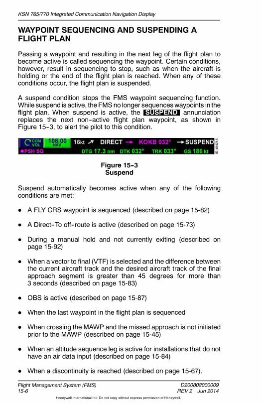
KSN 765/770 Integrated Communication Navigation Display
D200802000009REV 2 Jun 2014
Flight Management System (FMS)15-6
Honeywell International Inc. Do not copy without express permission of Honeywell.
WAYPOINT SEQUENCING AND SUSPENDING AFLIGHT PLAN
Passing a waypoint and resulting in the next leg of the flight plan tobecome active is called sequencing the waypoint. Certain conditions,however, result in sequencing to stop, such as when the aircraft isholding or the end of the flight plan is reached. When any of theseconditions occur, the flight plan is suspended.
A suspend condition stops the FMS waypoint sequencing function.While suspend is active, theFMSno longer sequenceswaypoints in theflight plan. When suspend is active, the SUSPEND annunciationreplaces the next non--active flight plan waypoint, as shown inFigure 15--3, to alert the pilot to this condition.
Figure 15--3Suspend
Suspend automatically becomes active when any of the followingconditions are met:
D A FLY CRS waypoint is sequenced (described on page 15-82)
D A Direct--To off--route is active (described on page 15-73)
D During a manual hold and not currently exiting (described onpage 15-92)
D When a vector to final (VTF) is selected and the difference betweenthe current aircraft track and the desired aircraft track of the finalapproach segment is greater than 45 degrees for more than3 seconds (described on page 15-83)
D OBS is active (described on page 15-87)
D When the last waypoint in the flight plan is sequenced
D When crossing the MAWP and the missed approach is not initiatedprior to the MAWP (described on page 15-45)
D When an altitude sequence leg is active for installations that do nothave an air data input (described on page 15-84)
D When a discontinuity is reached (described on page 15-67).

KSN 765/770 Integrated Communication Navigation Display
D200802000009REV 2 Jun 2014 15-7
Flight Management System (FMS)
Honeywell International Inc. Do not copy without express permission of Honeywell.
Suspend is automatically exited when any of the following occurs:
D A Direct--To an active flight plan waypoint is selected
D The FROM leg in the flight plan is activated
D The active flight plan is changed.
D When the aircraft heading intercepts the active leg in the flight plan.
FMS FUNCTION DISPLAY
The FMS function is displayed by pushing the FMS bezel key. Whenpushed, the page 1/3 layout of the FMS function is displayed, shownin Figure 15--4. Pushing thePAGE bezel key toggles through the threeFMS function layouts.
Figure 15--4FMS Function Overview

KSN 765/770 Integrated Communication Navigation Display
D200802000009REV 2 Jun 2014
Flight Management System (FMS)15-8
Honeywell International Inc. Do not copy without express permission of Honeywell.
The FMS page display is divided into the following sections:
D FMS home window
D Waypoint list window
D Navigation map window.
The waypoint list window, shown in Figure 15--5, provides a textualrepresentation of the flight plan. The textual presentation combinespath definition (course and distance) with performance data (estimatedtime en route (ETE)). A secondary role of the waypoint list is to supportthe flight plan map data. The flight plan modifications within thewaypoint list are displayed graphically on the NAV MAP.
NOTE: ETE is dashed in all views when on the ground.
Figure 15--5Waypoint List Window
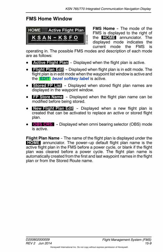
KSN 765/770 Integrated Communication Navigation Display
D200802000009REV 2 Jun 2014 15-9
Flight Management System (FMS)
Honeywell International Inc. Do not copy without express permission of Honeywell.
FMS Home Window
FMS Home -- The mode of theFMS is displayed to the right ofthe HOME annunciator. Thedisplayed mode indicates thecurrent mode the FMS is
operating in. The possible FMS modes and description of each modeare as follows:
D Active Flight Plan -- Displayed when the flight plan is active.
D Flight Plan Edit -- Displayed when flight plan is in edit mode. Theflight plan is in edit modewhen thewaypoint list window is active andthe EDIT bezel softkey label is active.
D Stored FP List -- Displayed when stored flight plan names aredisplayed in the waypoint window.
D FP Store Name -- Displayed when the flight plan name can bemodified before being stored.
D New Flight Plan Edit -- Displayed when a new flight plan iscreated that can be activated to replace an active or stored flightplan.
D OBS CRS: -- Displayed when omni bearing selector (OBS) modeis active.
Flight Plan Name -- The name of the flight plan is displayed under theHOME annunciator. The power--up default flight plan name is theactive flight plan in the FMS before a power cycle, or blank if the flightplan was cleared before a power cycle. The flight plan name isautomatically created from the first and last waypoint names in the flightplan or from the Stored Route name.
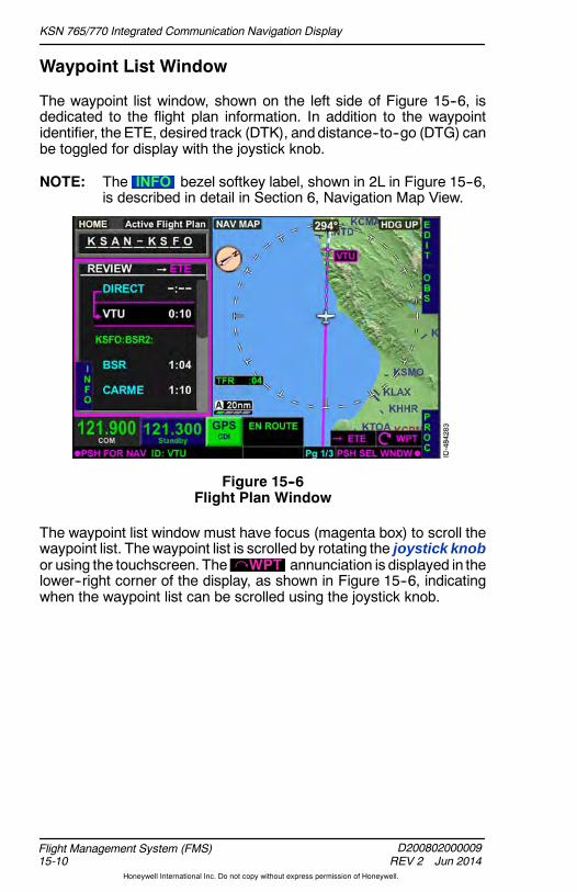
KSN 765/770 Integrated Communication Navigation Display
D200802000009REV 2 Jun 2014
Flight Management System (FMS)15-10
Honeywell International Inc. Do not copy without express permission of Honeywell.
Waypoint List Window
The waypoint list window, shown on the left side of Figure 15--6, isdedicated to the flight plan information. In addition to the waypointidentifier, the ETE, desired track (DTK), anddistance--to--go (DTG) canbe toggled for display with the joystick knob.
NOTE: The INFO bezel softkey label, shown in 2L in Figure 15--6,is described in detail in Section 6, Navigation Map View.
Figure 15--6Flight Plan Window
The waypoint list window must have focus (magenta box) to scroll thewaypoint list. Thewaypoint list is scrolled by rotating the joystick knobor using the touchscreen. The WPT annunciation is displayed in thelower--right corner of the display, as shown in Figure 15--6, indicatingwhen the waypoint list can be scrolled using the joystick knob.
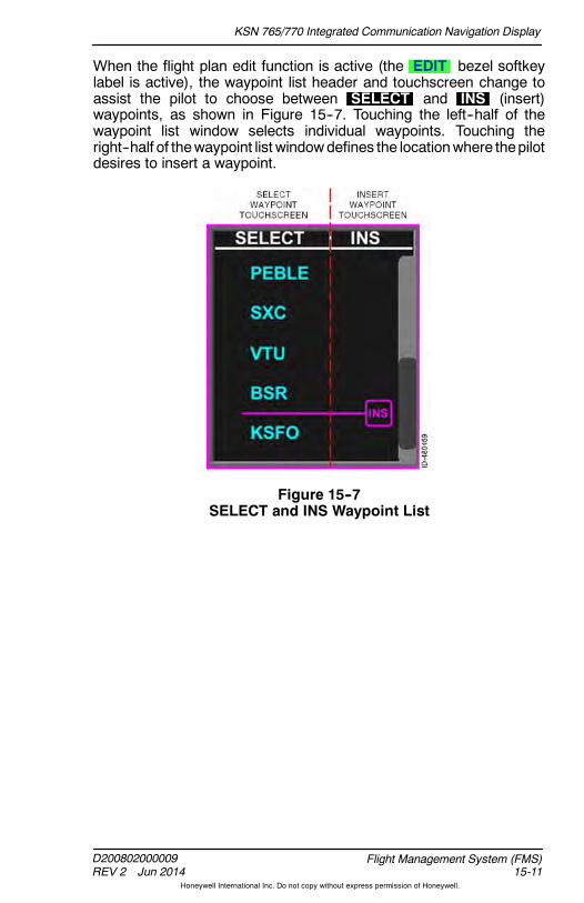
KSN 765/770 Integrated Communication Navigation Display
D200802000009REV 2 Jun 2014 15-11
Flight Management System (FMS)
Honeywell International Inc. Do not copy without express permission of Honeywell.
When the flight plan edit function is active (the EDIT bezel softkeylabel is active), the waypoint list header and touchscreen change toassist the pilot to choose between SELECT and INS (insert)waypoints, as shown in Figure 15--7. Touching the left--half of thewaypoint list window selects individual waypoints. Touching theright--half of thewaypoint list windowdefines the locationwhere thepilotdesires to insert a waypoint.
Figure 15--7SELECT and INS Waypoint List

KSN 765/770 Integrated Communication Navigation Display
D200802000009REV 2 Jun 2014
Flight Management System (FMS)15-12
Honeywell International Inc. Do not copy without express permission of Honeywell.
EXAMPLE FLIGHT PLAN
A typical flight from San Diego International Airport (KSAN) to SanFrancisco International Airport (KSFO) is used as an example for thissection. Table 15--1 lists the details pertaining to the flight.
Table 15--1Flight Data San Diego to San Francisco
Departure Airport San Diego International (KSAN)
Destination Airport San Francisco International(KSFO)
Flight Plan Routing as filed is as followingKSANPEBLE4.SXC V208 VTU V25 DEANO BSR BSR2
KSFO
Flight Plan Route Entry
The waypoint list window, shown in Figure 15--8, permits the pilot toselect, review, and insert departure (SIDs) and arrival procedures(STARs and approaches) from the FMS navigation database.
Figure 15--8Waypoint List Window

KSN 765/770 Integrated Communication Navigation Display
D200802000009REV 2 Jun 2014 15-13
Flight Management System (FMS)
Honeywell International Inc. Do not copy without express permission of Honeywell.
The waypoint window is selected by pushing in the joystick knob totoggle between the three windows on page 1/3 of the FMS functionlayout or by using the touchscreen to directly select a window. Whenthe waypoint window is selected, a magenta box is displayed around it,as shown in Figure 15--8.
NOTE: When the waypoint window is selected, the auto--rangefeature on the map display is inactive.
When the waypoint window is selected, EDIT , OBS , and PROCbezel softkey labels are displayed. Selecting the EDIT bezel softkeypermits the pilot to edit the flight plan.
When the EDIT bezel softkey label is active, FMS mode changes toFlight Plan Edit and a magenta INS icon is displayed in thewaypoint window, as shown in Figure 15--9.
Figure 15--9Insert Prompt
Other bezel softkey labels displayed when EDIT is selected are insert( INS ), clear ( CLR ), and procedure ( PROC ).
The pilot can insert a waypoint by either pushing the INS bezel softkeyor by pushing the INS icon on the touchscreen.

KSN 765/770 Integrated Communication Navigation Display
D200802000009REV 2 Jun 2014
Flight Management System (FMS)15-14
Honeywell International Inc. Do not copy without express permission of Honeywell.
Selecting the INS bezel softkey displays theINSERT NEW WAYPOINT pop--up window, shown in Figure 15--10,which permits the pilot to select airports, NAVAIDs, intersections, anduser waypoints to add to the flight plan.
Figure 15--10FMS Pop--Up Window
Pushing the bezel softkey in 1R (shown as APT in Figure 15--10)toggles through nearest waypoint lists in the following order:
Airports NAVAIDs Intersections Repeat
The pilot can also directly select the nearest airports, NAVAIDs, orintersections list by using the touchscreen to select the touchscreenbutton displayed in the pop--up header.
The pop--up window can be scrolled vertically by rotating the joystickknob or using the touchscreen to highlight the desired waypoint. Whenthe desiredwaypoint is highlighted, thewaypoint is selected by pushingthe OK bezel softkey, pushing in the joystick knob, or by touching thedesired waypoint twice on the touchscreen.

KSN 765/770 Integrated Communication Navigation Display
D200802000009REV 2 Jun 2014 15-15
Flight Management System (FMS)
Honeywell International Inc. Do not copy without express permission of Honeywell.
For the example flight plan, KSAN is the desired departure airport andis selected by highlighting KSAN in thepop--upwindowand pushing theOK bezel softkey shown in Figure 15--10. The resulting display isshown in Figure 15--11.
Figure 15--11Departure Airport Selected
The flight plan name field, shown in Figure 15--11 as KSAN--KSAN ,defaults to the first and last waypoint in the waypoint list. Since KSANis the first and last waypoint in the waypoint list, KSAN is displayed asthe departure and destination airport. When another waypoint isentered after KSAN, the destination will update automatically in theflight plan name field.
For the example flight plan, KSFO is the desired destination airport. Toinsert KSFOafter KSAN in the FMS flight plan list, ensure the INS iconis displayed after KSAN, as shown in Figure 15--11, by rotating thejoystick knob.
NOTE: When the INS icon is displayed in thewaypoint list, the INSbezel softkey label is displayed at 2R.

KSN 765/770 Integrated Communication Navigation Display
D200802000009REV 2 Jun 2014
Flight Management System (FMS)15-16
Honeywell International Inc. Do not copy without express permission of Honeywell.
Selecting the INS bezel softkey displays theINSERT NEW WAYPOINT pop--up window. KSFO is the desireddestination airport, however it is not displayed in the nearest airportspop--up window. When a desired waypoint is not displayed in thepop--upwindow, thewaypoint can bemanually entered by selecting themanual input area just below the INSERT NEW WAYPOINT header,then changing the characters one at a time using the joystick knob. Thejoystick knob is then toggled left and right between the character fieldsand the joystick knob is rotated to change the character in each field.
Alternatively, the touchscreen can be used to enter a desired waypointby selecting the waypoint identifier field, shown in Figure 15--12.
Figure 15--12Insert New Waypoint Pop--Up Window

KSN 765/770 Integrated Communication Navigation Display
D200802000009REV 2 Jun 2014 15-17
Flight Management System (FMS)
Honeywell International Inc. Do not copy without express permission of Honeywell.
When selected, the QWERTY keypad pop--up window shown inFigure 15--13 is displayed.
Figure 15--13QWERTY Pop--Up Window
The desired waypoint, KSFO for the example flight plan, is enteredusing the touchscreen keypad, shown in Figure 15--14. Selecting theOK prompt inserts thewaypoint into the flight plan. The BACK bezelsoftkey returns to the INSERT NEW WAYPOINT display withoutinserting a new waypoint.
Figure 15--14KSFO Entered on QWERTY Keypad

KSN 765/770 Integrated Communication Navigation Display
D200802000009REV 2 Jun 2014
Flight Management System (FMS)15-18
Honeywell International Inc. Do not copy without express permission of Honeywell.
For the example flight plan, OK is pushed on the touchscreen andKSFO is inserted into the flight plan, as shown in Figure 15--15.
Figure 15--15KSAN--KSFO Flight Plan
Departure Procedures
A standard instrument departure (SID) procedure can be entered intothe FMS flight plan. To enter a SID, the departure airport mustpreviously be entered into the flight plan.
To insert a departure procedure into the flight plan, push the PROCbezel softkey, shown in Figure 15--16.
Figure 15--16Inserting Departure Procedure
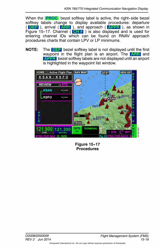
KSN 765/770 Integrated Communication Navigation Display
D200802000009REV 2 Jun 2014 15-19
Flight Management System (FMS)
Honeywell International Inc. Do not copy without express permission of Honeywell.
When the PROC bezel softkey label is active, the right--side bezelsoftkey labels change to display available procedures: departure( DEP ), arrival ( ARR ), and approach ( APPR ), as shown inFigure 15--17. Channel ( CH # ) is also displayed and is used forentering channel IDs which can be found on RNAV approachprocedures charts that contain LPV or LP minimums.
NOTE: The DEP bezel softkey label is not displayed until the firstwaypoint in the flight plan is an airport. The ARR andAPPR bezel softkey labels are not displayed until an airportis highlighted in the waypoint list window.
Figure 15--17Procedures
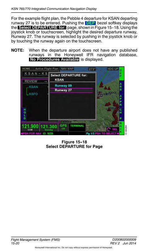
KSN 765/770 Integrated Communication Navigation Display
D200802000009REV 2 Jun 2014
Flight Management System (FMS)15-20
Honeywell International Inc. Do not copy without express permission of Honeywell.
For the example flight plan, the Pebble 4 departure for KSANdepartingrunway 27 is to be entered. Pushing the DEP bezel softkey displaysthe Select DEPARTURE for: page, shown inFigure 15--18. Using thejoystick knob or touchscreen, highlight the desired departure runway,Runway 27. The runway is selected by pushing in the joystick knob orby touching the runway again on the touchscreen.
NOTE: When the departure airport does not have any publishedrunways in the Honeywell IFR navigation database,No Procedures Available is displayed.
Figure 15--18Select DEPARTURE for Page

KSN 765/770 Integrated Communication Navigation Display
D200802000009REV 2 Jun 2014 15-21
Flight Management System (FMS)
Honeywell International Inc. Do not copy without express permission of Honeywell.
When the desired runway is selected, all available departureprocedures for the selected runway are displayed. Departureprocedures are highlighted using the joystick knob or touchscreen. Thedeparture procedure is selected by pushing in the joystick knob ortouching the departure procedure again on the touchscreen. For theexample flight plan, PEBLE4 is selected, as shown in Figure 15--19.
Figure 15--19Departure Procedure for Page

KSN 765/770 Integrated Communication Navigation Display
D200802000009REV 2 Jun 2014
Flight Management System (FMS)15-22
Honeywell International Inc. Do not copy without express permission of Honeywell.
When the departure procedure is selected, available departuretransitions are displayed, as shown in Figure 15--20. Departuretransitions are highlighted using the joystick knob or touchscreen. Thedeparture transition is selected by pushing in the joystick knob ortouching the transition again on the touchscreen.
NOTE: When a departure transition is not available,No Transitions Press Joystick to Insert Procedure isdisplayed.
Figure 15--20Departure Procedure Transition Page

KSN 765/770 Integrated Communication Navigation Display
D200802000009REV 2 Jun 2014 15-23
Flight Management System (FMS)
Honeywell International Inc. Do not copy without express permission of Honeywell.
For the example flight plan, SXC is selected and the departureprocedure and transition are inserted into the flight plan. The resultingdisplay is shown in Figure 15--21.
Figure 15--21SID Inserted Into the Flight Plan
Departure procedure altitude sequenced waypoints and otherunnamed waypoints are also inserted into the flight plan.
When a departure procedure is inserted into the flight plan, the flightplans origin (the first waypoint) is changed to the selected runway in theformat of RWXX where XX is the selected departure runway.

KSN 765/770 Integrated Communication Navigation Display
D200802000009REV 2 Jun 2014
Flight Management System (FMS)15-24
Honeywell International Inc. Do not copy without express permission of Honeywell.
En Route Waypoints
To insert en route waypoints, the EDIT bezel softkey label must beactive. When in flight plan edit mode, the joystick knob is rotated untilthe INS icon is displayed between the waypoints where the en routewaypoint is to be added, as shown in Figure 15--22.
Figure 15--22Inserting En Route Waypoints
Alternatively, instead of using the joystick knob to select the insert( INS ) location in the waypoint list, the touchscreen can be used toselect the insert location. While the flight plan edit mode is active, theINS header is displayed at the top of the waypoint list. Whendisplayed, touching the right--half of thewaypoint list display selects theinsert location.
For the example flight plan, the en route portion begins at SXC onVector 208 to Ventura VOR (V208.VTU). However, before an airwaycan be loaded, the beginning and ending NAVAID or fix must beentered. To enter VTU into the flight plan list, push the INS bezelsoftkey, shown in Figure 15--22.

KSN 765/770 Integrated Communication Navigation Display
D200802000009REV 2 Jun 2014 15-25
Flight Management System (FMS)
Honeywell International Inc. Do not copy without express permission of Honeywell.
When the INS bezel softkey is pushed, theINSERT NEW WAYPOINT pop--up window is displayed. Pushing theAPT bezel softkey displays the nearest NAVAIDS list, shown inFigure 15--23.
NOTE: The nearest NAVAIDs waypoint list can also be displayed bypushing the NAV touchscreen button on the top of thepop--up window.
Figure 15--23Insert VOR Waypoint
VTU is the desired waypoint, however it is not displayed in the nearestNAVAIDS waypoint list. When a waypoint is not found on the pop--upwindow, the waypoint can bemanually entered by rotating and togglingthe joystick knob or by using the touchscreen to touch the waypointidentifier displayed just below the INSERT NEW WAYPOINT header( NZY shown in Figure 15--23) twice. For this example, thetouchscreen is used to manually enter the waypoint name, as thismethod is usually faster.

KSN 765/770 Integrated Communication Navigation Display
D200802000009REV 2 Jun 2014
Flight Management System (FMS)15-26
Honeywell International Inc. Do not copy without express permission of Honeywell.
Whenselected, theQWERTY keypadpop--upwindow is displayed. Forthe example flight plan, VTU is manually entered, as shown inFigure 15--24. Selecting OK inserts the waypoint into the flight plan.
Figure 15--24Insert VOR
The resulting display of VTU inserted into the flight plan is shown inFigure 15--25.
Figure 15--25VOR Inserted Into Flight Plan

KSN 765/770 Integrated Communication Navigation Display
D200802000009REV 2 Jun 2014 15-27
Flight Management System (FMS)
Honeywell International Inc. Do not copy without express permission of Honeywell.
When the beginning and endwaypoints are inserted into the flight plan,the airway can be inserted. To enter an airway, push the INS bezelsoftkey which displays the INSERT NEW WAYPOINT pop--upwindow shown in Figure 15--26.
Figure 15--26Insert Airway
Pushing the AWY bezel softkey displays the INSERT WAYPOINTSVIA AIRWAY QWERTY keypad. When the QWERTY keypad isdisplayed, the desired airway can be entered. For the example flightplan, V208 is the desired airway and is entered using the keypad, asshown in Figure 15--27.
Figure 15--27Insert Waypoints Via Airway

KSN 765/770 Integrated Communication Navigation Display
D200802000009REV 2 Jun 2014
Flight Management System (FMS)15-28
Honeywell International Inc. Do not copy without express permission of Honeywell.
Pushing OK or pushing in the joystick knob inserts the airway into theflight plan. All waypoints on the airway that define the route are insertedinto the flight plan, as shown in Figure 15--28. The FMS messageAIRWAY ADDED is displayed.
NOTE: The FMS message NOT IN DATA BASE is displayed if aninvalid airway is entered.
Figure 15--28Airway Inserted Into Flight Plan
For the example flight plan, the planned route after VTU is to proceedvia Victor 25 to the DEANO intersection (V25.DEANO) and thenVictor 27 to the Big Sur VOR (V27.BSR). The Victor airway andwaypoint combination for the remainder of the flight are entered into theflight plan as previously described.

KSN 765/770 Integrated Communication Navigation Display
D200802000009REV 2 Jun 2014 15-29
Flight Management System (FMS)
Honeywell International Inc. Do not copy without express permission of Honeywell.
Arrival Procedures
Standard terminal arrival routes (STARs) are contained in the NAVdatabase and can be inserted into the flight plan. To insert a STAR intothe flight plan, push the PROC bezel softkey, shown in Figure 15--29,while in flight plan edit mode.
NOTE: Some approaches and STARs are not in the database. Thisis because of the way some procedures are defined by thecontrolling agency and the limitations of the FMS.
Figure 15--29Entering Arrival Procedures
The PROC bezel softkey label is displayed when the FMS waypointlist window has focus or when the HOME window has focus on page1/3 of the FMS bezel softkey labels (described later in this section).When the FMS waypoint list has focus, an airport (or runway) must behighlighted in the waypoint list window to display selectable arrival andapproach prompts. Otherwise the ARR and APPR bezel softkeylabels are not displayed.When the HOME window has focus, pushingthe PROC bezel softkey displays selectable ARR and APPR bezelsoftkey labels when the destination airport is the last waypoint in theFMS waypoint list.
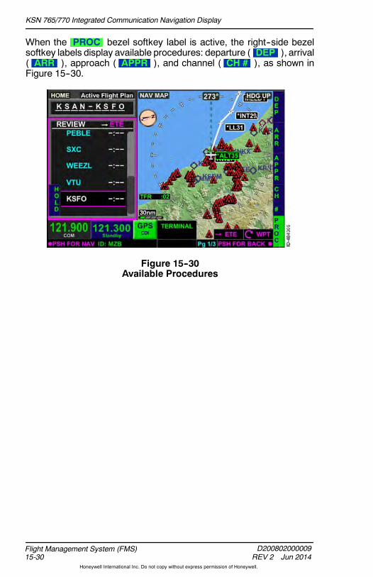
KSN 765/770 Integrated Communication Navigation Display
D200802000009REV 2 Jun 2014
Flight Management System (FMS)15-30
Honeywell International Inc. Do not copy without express permission of Honeywell.
When the PROC bezel softkey label is active, the right--side bezelsoftkey labels display available procedures: departure ( DEP ), arrival( ARR ), approach ( APPR ), and channel ( CH # ), as shown inFigure 15--30.
Figure 15--30Available Procedures
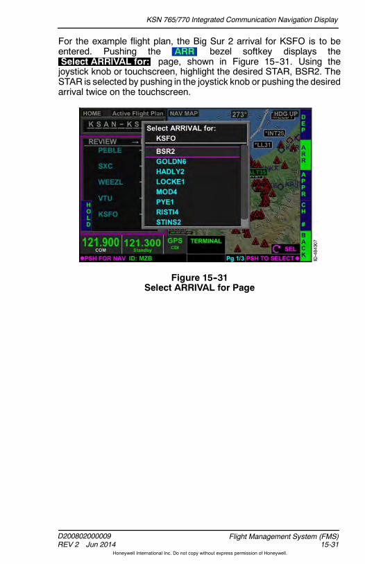
KSN 765/770 Integrated Communication Navigation Display
D200802000009REV 2 Jun 2014 15-31
Flight Management System (FMS)
Honeywell International Inc. Do not copy without express permission of Honeywell.
For the example flight plan, the Big Sur 2 arrival for KSFO is to beentered. Pushing the ARR bezel softkey displays theSelect ARRIVAL for: page, shown in Figure 15--31. Using thejoystick knob or touchscreen, highlight the desired STAR, BSR2. TheSTAR is selected by pushing in the joystick knob or pushing the desiredarrival twice on the touchscreen.
Figure 15--31Select ARRIVAL for Page

KSN 765/770 Integrated Communication Navigation Display
D200802000009REV 2 Jun 2014
Flight Management System (FMS)15-32
Honeywell International Inc. Do not copy without express permission of Honeywell.
When the desired STAR is selected, available arrival transitions for theselected STAR are displayed (when the selected STAR has atransition). Arrival transitions are highlighted using the joystick knob ortouchscreen. For theexample flight plan, no transitions are available forthe BSR2 arrival. When a STAR does not have a transition,No Transitions Press Joystick to Insert Procedure is displayedon the arrival transition page. Pushing in the joystick knob inserts theSTAR into the flight plan without a transition. The resulting display isshown in Figure 15--32.
NOTE: Altitude restrictions are not inserted into the flight plan.
Figure 15--32STAR Inserted Into the Flight Plan

KSN 765/770 Integrated Communication Navigation Display
D200802000009REV 2 Jun 2014 15-33
Flight Management System (FMS)
Honeywell International Inc. Do not copy without express permission of Honeywell.
Approach Procedures
The KSN 765/770 meets the requirements of TSO--C146C andAC 20--138C and is a suitable RNAV system as defined in theAeronautical Information Manual (AIM).
There may be differences between courses displayed on the chart andthose on the display. These differences are the result of changes inmagnetic variation and are normally less than 2 degrees. Verifypossible changes before starting an approach by checking theapproach chart against the flight plan.
NOTE: When an ILS, LOC, or LOCBC typeapproaches are selectedwith an EFIS 40/50 installed while in GPS mode, the displaywill show a X and not provide any navigation information asa reminder to the pilot to switch to the appropriate navigationsource (LOC) on the EFIS 40/50.
USING GPS GUIDANCE ON AN APPROACH
Only approaches with the initials GPS in the title can be conductedusing the FMS. For example, RNAV (GPS) RWY 22 or RNAV (GPS)Y RWY 27 or VOR or GPS--A can all be flown using the KSN WAASGPS. Other approaches, such as VOR RWY 22 cannot be flown usingthe GPS as the primary source of navigation, though GPS can be usedto monitor the approach. Refer to the AIM Chapter 5 section titledGlobal Positioning System (GPS) for more information regarding theacceptable use of GPS equipment.
When flying an approach using ground--based equipment, the pilotmust transition to navigation using signals from the ground--basedequipment at the final approach waypoint (FAWP). For NDB, VOR, orILS approaches the primary navigation instruments are the ADFneedle, the VOR driven CDI or HSI, or the LOC/GS indications on theCDI or HSI, respectively.
The following paragraphs describe the various approaches that can beflown
D VOR, VOR/DME, NDB, and NDB/DME approaches have a GPSoverlay in the database that permits monitoring of the approachusing GPS. The ground--based VOR or NDB signals must be usedfor primary approach guidance and the altitude restrictions on theapproach must be met. GPS guidance with advisory verticalguidance can only be used to monitor the approach. A prompt toremind the pilot to switch to VLOC on a VOR approach is notprovided.

KSN 765/770 Integrated Communication Navigation Display
D200802000009REV 2 Jun 2014
Flight Management System (FMS)15-34
Honeywell International Inc. Do not copy without express permission of Honeywell.
D When an approach has VOR or GPS or NDB or GPS in the title,GPS can be used for approach guidance. The altitude restrictionsmust be met. GPS with advisory vertical guidance can be used tomonitor the VORor NDBapproachwhendesired. Lateral deviationsare approved for navigation when the APPROACH annunciator isdisplayed prior to the FAWP and the loss of integrity ( LOI )annunciator is not displayed.
D When aGPS orRNAV (GPS) approachwithout LNAV/VNAV or LPVminimums is flown, the GPS must be used for approach guidanceand the altitude restrictions on the approach must be met. Advisoryvertical guidance is provided. Lateral deviations are approved fornavigationwhen the APPROACH annunciator is displayedand theloss of integrity ( LOI ) annunciator is not displayed. LNAV+Vand LP+V are examples of annunciations displayed in theapproach mode guidance field to indicate the type of approachflown.
D When a GPS or RNAV (GPS) approach with LNAV/VNAV or LPVminimums is flown, the GPS must be used for approach guidance.The vertical guidance is surveyed and is not advisory. Displayedlateral and vertical deviations are approved for navigation when theAPPROACH annunciator is displayed and the loss of integrity( LOI ) annunciator is not displayed. LPV or LNAV/VNAV isdisplayed in the approach mode guidance field to indicate the typeof approach flown. These approaches terminate at the decisionaltitude (DA) for LPV and LNAV/VNAV minimums.
The FMS will automatically select LPV if available on an RNAVapproach. If the GPS is detected as unfavorable, the system canfail--down to LNAV. The approach annunciation box will identify theapproach type, and the pilot should fly to the appropriateminimums.
D When a LOC, LOC (BACK CRS), SDF, LDA, IGS, or TACANapproach is flown, the ground--based signals must be used forprimary approach guidance and the altitude restrictions on theapproach must be met. The GPS may be used to monitor theapproach. There is no advisory vertical guidance for back courseapproaches. Auto--tune and auto--switching of the localizer isavailablewhenconfigured.Whennot configured for auto--switching,a prompt to remind the flight crew to switch to VLOC is not provided.
NOTE: When configured on installation, the KSN 770 radio willautomatically tune the standby NAV frequency and switchthe standby NAV frequency to the active NAV frequencyat the appropriate time. The system will not automaticallyswitch back to GPS during a missed approach. For adetailed description of the NAV radio autotune feature,see Section 5, KSN 770 Radio.

KSN 765/770 Integrated Communication Navigation Display
D200802000009REV 2 Jun 2014 15-35
Flight Management System (FMS)
Honeywell International Inc. Do not copy without express permission of Honeywell.
D When an ILS approach is flown, the ground--based signals must beused for primary approach guidance. The GPS may be used tomonitor the approach. Advisory vertical guidance is provided.Auto--tune and auto--switching of the localizer is available whenconfigured. When not configured for auto--switching, a prompt toremind the flight crew to switch to VLOC is not provided.
ADVISORY VERTICAL GUIDANCE
Advisory vertical guidance is displayed when permitted by the selectedapproach and as long as sufficient health and integrity exists within theGPS. Advisory vertical guidance is indicated for some approaches bya +V appended to the approach annunciation in the approach modeguidance field. If the vertical integrity degrades, the vertical deviationsare flagged invalid.
NOTE: Table 15--2 lists each type of approach supported and ifvertical deviations are provided for each approach.
CAUTION
ADVISORY VERTICAL GUIDANCE DEVIATION INFORMATIONIS ONLY AN AID TO HELP PILOTS COMPLY WITH ALTITUDERESTRICTIONS. WHEN USING ADVISORY VERTICALGUIDANCE, THE PILOT MUST USE THE PRIMARYBAROMETRIC ALTIMETER TO ENSURE COMPLIANCE WITHALL ALTITUDE RESTRICTIONS, PARTICULARLY DURINGINSTRUMENT APPROACH OPERATIONS. ADVISORYVERTICAL GUIDANCE IS REMOVED AT THE MISSEDAPPROACH POINT.
Uncertified, but FAA--sanctioned, advisory vertical guidance isgenerally provided by a published vertical descent angle. Sometimesthe glide path is computed as a geometric path between twowaypoints.These approaches are non--precision and the minimums identified onthe approach as minimum descent altitude (MDA). Minimums may bereached prior to the missed approach point. The advisory glide pathmay not meet every intermediate altitude crossing restriction. The pilotin command is responsible to meet all altitude crossing restrictions.
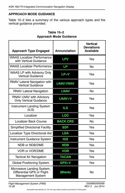
KSN 765/770 Integrated Communication Navigation Display
D200802000009REV 2 Jun 2014
Flight Management System (FMS)15-36
Honeywell International Inc. Do not copy without express permission of Honeywell.
APPROACH MODE GUIDANCE
Table 15--2 lists a summary of the various approach types and thevertical guidance provided.
Table 15--2Approach Mode Guidance
Approach Type Engaged Annunciation
VerticalDeviationsAvailable
WAAS Localizer Performancewith Vertical Guidance LPV Yes
WAAS Localizer Performance LP No
WAAS LP with Advisory OnlyVertical Guidance LP+V Yes
RNAV Lateral Navigation withVertical Guidance LNAV/VNAV Yes
RNAV Lateral Navigation LNAV No
RNAV LNAV with AdvisoryOnly Vertical Guidance LNAV+V Yes
Instrument Landing System(ILS) ILS Yes
Localizer LOC Yes
Localizer Back Course BACK CRS No
Simplified Directional Facility SDF Yes
Localizer Type Directional Aid LDA Yes
Instrument Guidance System IGS Yes
NDB or NDB/DME NDB Yes
VOR or VOR/DME VOR Yes
Tactical Air Navigation TACAN Yes
Global Positioning System GPS+V Yes
Microwave Landing System,Differential GPS or FlightManagement System
(Blank) No

KSN 765/770 Integrated Communication Navigation Display
D200802000009REV 2 Jun 2014 15-37
Flight Management System (FMS)
Honeywell International Inc. Do not copy without express permission of Honeywell.
CIRCLING APPROACHES
Circling approaches are identified with the word CIRCLE in place ofthe runway designation on the Select APPROACH for: page.Whena circling approach is activated, the approach is constructed with theMAWP followed by the airport waypoint and associated missedapproach procedure. A discontinuity is automatically inserted betweenthe MAWP and the airport waypoint. The FMS does not provideguidance for the circling maneuver once the approach is completed(crossing theMAWP, orwhen thepilot has acquired the airport visually).
NOTE: When thediscontinuity is deletedbetween theMAWPand theairport, the FMS provides guidance to turn to the center of theairport after crossing the MAWP.
When the MA bezel softkey is pushed, the discontinuity and airportwaypoint are removed from the active flight plan. Also, the missedapproach procedure after the MAWP becomes part of the active flightplan.
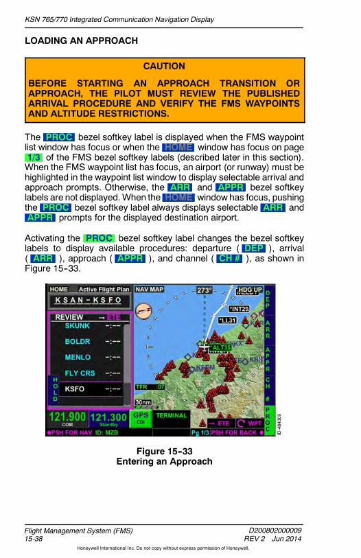
KSN 765/770 Integrated Communication Navigation Display
D200802000009REV 2 Jun 2014
Flight Management System (FMS)15-38
Honeywell International Inc. Do not copy without express permission of Honeywell.
LOADING AN APPROACH
CAUTION
BEFORE STARTING AN APPROACH TRANSITION ORAPPROACH, THE PILOT MUST REVIEW THE PUBLISHEDARRIVAL PROCEDURE AND VERIFY THE FMS WAYPOINTSAND ALTITUDE RESTRICTIONS.
The PROC bezel softkey label is displayed when the FMS waypointlist window has focus or when the HOME window has focus on page1/3 of the FMS bezel softkey labels (described later in this section).When the FMS waypoint list has focus, an airport (or runway) must behighlighted in the waypoint list window to display selectable arrival andapproach prompts. Otherwise, the ARR and APPR bezel softkeylabels are not displayed.When the HOME window has focus, pushingthe PROC bezel softkey label always displays selectable ARR andAPPR prompts for the displayed destination airport.
Activating the PROC bezel softkey label changes the bezel softkeylabels to display available procedures: departure ( DEP ), arrival( ARR ), approach ( APPR ), and channel ( CH # ), as shown inFigure 15--33.
Figure 15--33Entering an Approach

KSN 765/770 Integrated Communication Navigation Display
D200802000009REV 2 Jun 2014 15-39
Flight Management System (FMS)
Honeywell International Inc. Do not copy without express permission of Honeywell.
For the example flight plan, the ILS 28R approach for KSFO is to beentered. Pushing the APPR bezel softkey shown in Figure 15--33,displays the Select APPROACH for: page shown in Figure 15--34.Using the touchscreen or joystick knob, the ILS 28R approach ishighlighted. The approach is selected by pushing in the joystick knob.
Figure 15--34Select APPROACH for Page

KSN 765/770 Integrated Communication Navigation Display
D200802000009REV 2 Jun 2014
Flight Management System (FMS)15-40
Honeywell International Inc. Do not copy without express permission of Honeywell.
When the desired approach is selected, all available approachtransitions are displayed, as shown in Figure 15--35. Approachtransitions are selected by using the joystick knob or touchscreen.
NOTE: An approach transition must be selected even when noapproach transition is desired. Any undesired approachtransition waypoints must manually be deleted from the flightplan waypoint list.
Figure 15--35Approach Transition Page
If the approach is loaded and later has to be changed, select theapproach in the flight plan list and push APPR to bring up the list ofapproaches. Initially, only the approaches available to the same runwayare displayed. To display a complete list of approaches to the sameairport, the current approach must be deleted.
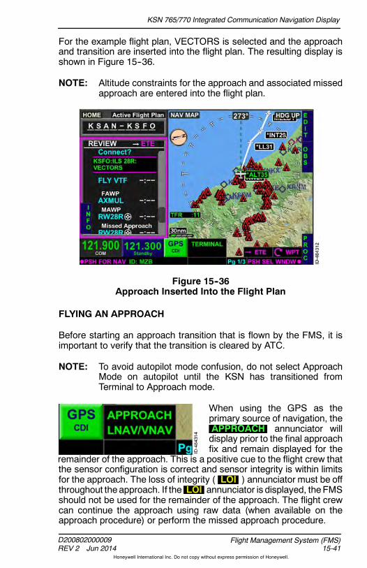
KSN 765/770 Integrated Communication Navigation Display
D200802000009REV 2 Jun 2014 15-41
Flight Management System (FMS)
Honeywell International Inc. Do not copy without express permission of Honeywell.
For the example flight plan, VECTORS is selected and the approachand transition are inserted into the flight plan. The resulting display isshown in Figure 15--36.
NOTE: Altitude constraints for the approach and associated missedapproach are entered into the flight plan.
Figure 15--36Approach Inserted Into the Flight Plan
FLYING AN APPROACH
Before starting an approach transition that is flown by the FMS, it isimportant to verify that the transition is cleared by ATC.
NOTE: To avoid autopilot mode confusion, do not select ApproachMode on autopilot until the KSN has transitioned fromTerminal to Approach mode.
When using the GPS as theprimary source of navigation, theAPPROACH annunciator willdisplay prior to the final approachfix and remain displayed for the
remainder of the approach. This is a positive cue to the flight crew thatthe sensor configuration is correct and sensor integrity is within limitsfor the approach. The loss of integrity ( LOI ) annunciator must be offthroughout theapproach. If the LOI annunciator is displayed, theFMSshould not be used for the remainder of the approach. The flight crewcan continue the approach using raw data (when available on theapproach procedure) or perform the missed approach procedure.

KSN 765/770 Integrated Communication Navigation Display
D200802000009REV 2 Jun 2014
Flight Management System (FMS)15-42
Honeywell International Inc. Do not copy without express permission of Honeywell.
CHANNEL ID
Approach charts with an RNAV approach procedure with LPVminimums contain a channel ID code, as shown in Figure 15--37. Thiscode can be entered into the display to quickly load the desiredapproach procedure.
Figure 15--37Channel ID on Approach Chart
When an approach is loaded from the CH # bezel softkey, it is loadedas a vector to final transition. In order to load the approach with apublished transition fix/route, the CH # bezel softkey should not beused. In that case, the approach should be loaded as describedpreviously.

KSN 765/770 Integrated Communication Navigation Display
D200802000009REV 2 Jun 2014 15-43
Flight Management System (FMS)
Honeywell International Inc. Do not copy without express permission of Honeywell.
To enter a channel ID, select the CH # bezel softkey shown inFigure 15--33. When the CH # bezel softkey label is active, theChannel ID window shown in Figure 15--38, is displayed.
Figure 15--38Channel ID
The channel ID is enteredusing the touchscreen. For the example flightplan, the RNAV (GPS) Z approach to runway 28R is desired and thechannel ID for the example approach is 81828. The channel ID isentered using the touchscreen and then pushing OK or pushing in thejoystick knob. When OK is pushed, the select approach transitionpage is displayed.
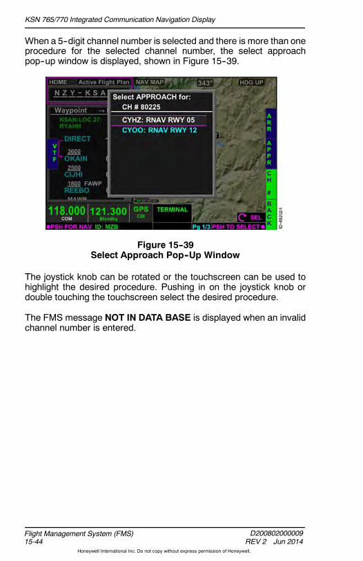
KSN 765/770 Integrated Communication Navigation Display
D200802000009REV 2 Jun 2014
Flight Management System (FMS)15-44
Honeywell International Inc. Do not copy without express permission of Honeywell.
When a 5--digit channel number is selected and there is more than oneprocedure for the selected channel number, the select approachpop--up window is displayed, shown in Figure 15--39.
Figure 15--39Select Approach Pop--Up Window
The joystick knob can be rotated or the touchscreen can be used tohighlight the desired procedure. Pushing in on the joystick knob ordouble touching the touchscreen select the desired procedure.
The FMS message NOT IN DATA BASE is displayed when an invalidchannel number is entered.

KSN 765/770 Integrated Communication Navigation Display
D200802000009REV 2 Jun 2014 15-45
Flight Management System (FMS)
Honeywell International Inc. Do not copy without express permission of Honeywell.
Missed Approach Procedures
The missed approach procedure is an integral part of the approachprocedure. The missed approach procedure begins at the MAWP, andis separated from the approach by a Missed Approach headerwithinthe waypoint list, as shown in Figure 15--40.
Figure 15--40Missed Approach Procedure
Themissed approach procedure is activatedby pushing the MA bezelsoftkey or by pushing the MA touchscreen button when the missedapproach pop--up window is displayed.
NOTE: Suspend is entered after crossing the MAWPand themissedapproach is not initiated prior to the MAWP. The CDI will goto FROM and the outbound course is the same as theinbound course. The flight plan is suspended until themissedapproach is selected.
The MA bezel softkey label is displayed when the FAWP of theapproach procedure is the active To waypoint and either the waypointlist or home field is selected.
NOTE: The MA bezel softkey label is not displayed when the NAVMAP window is selected.

KSN 765/770 Integrated Communication Navigation Display
D200802000009REV 2 Jun 2014
Flight Management System (FMS)15-46
Honeywell International Inc. Do not copy without express permission of Honeywell.
The missed approach pop--up window shown in Figure 15--41, isdisplayed when the missed approach waypoint is reached and themissed approach has not yet been activated by pushing the MA bezelsoftkey.When displayed, the pop--upwindow requires the pilot tomakea decision. Pushing the MA touchscreen button or bezel softkeyactivates the missed approach procedure. Pushing the CLEARtouchscreen button or bezel softkey removes the pop--up window anddoes not activate the missed approach procedure. The FMS remainsin Suspend when the CLEAR touchscreen button or bezel softkey ispushed.
NOTE: When the CLEAR touchscreen button bezel softkey ispushed, the missed approach can be later activated bypushing the FMS bezel key and then the MA bezel key.
Figure 15--41Missed Approach Pop--Up Window
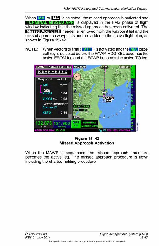
KSN 765/770 Integrated Communication Navigation Display
D200802000009REV 2 Jun 2014 15-47
Flight Management System (FMS)
Honeywell International Inc. Do not copy without express permission of Honeywell.
When MA or MA is selected, the missed approach is activated andTERMINAL MISSED APR is displayed in the FMS phase of flightwindow indicating that the missed approach has been activated. TheMissed Approach header is removed from the waypoint list and themissed approach waypoints and are added to the active flight plan, asshown in Figure 15--42.
NOTE: Whenvectors to final ( VTF ) is activatedand the MA bezelsoftkey is selected before the FAWP, HDGSEL becomes theactive FROM leg and the FAWP becomes the active TO leg.
Figure 15--42Missed Approach Activation
When the MAWP is sequenced, the missed approach procedurebecomes the active leg. The missed approach procedure is flownincluding the charted holding procedure.
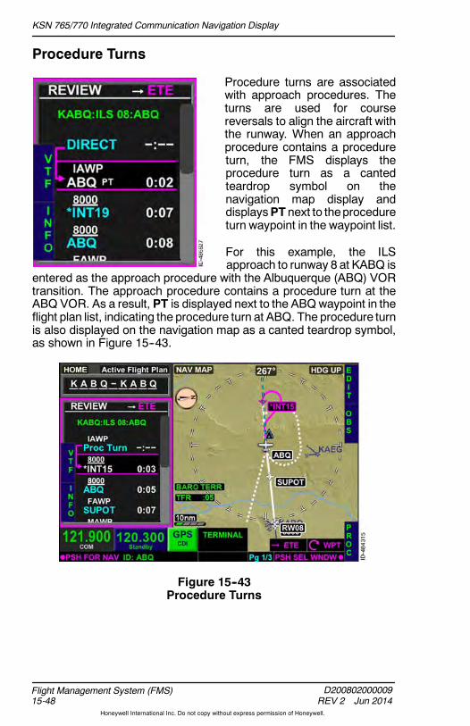
KSN 765/770 Integrated Communication Navigation Display
D200802000009REV 2 Jun 2014
Flight Management System (FMS)15-48
Honeywell International Inc. Do not copy without express permission of Honeywell.
Procedure Turns
Procedure turns are associatedwith approach procedures. Theturns are used for coursereversals to align the aircraft withthe runway. When an approachprocedure contains a procedureturn, the FMS displays theprocedure turn as a cantedteardrop symbol on thenavigation map display anddisplaysPT next to theprocedureturn waypoint in the waypoint list.
For this example, the ILSapproach to runway 8 at KABQ is
entered as the approach procedure with the Albuquerque (ABQ) VORtransition. The approach procedure contains a procedure turn at theABQ VOR. As a result, PT is displayed next to the ABQwaypoint in theflight plan list, indicating the procedure turn at ABQ. The procedure turnis also displayed on the navigation map as a canted teardrop symbol,as shown in Figure 15--43.
Figure 15--43Procedure Turns

KSN 765/770 Integrated Communication Navigation Display
D200802000009REV 2 Jun 2014 15-49
Flight Management System (FMS)
Honeywell International Inc. Do not copy without express permission of Honeywell.
Procedure turns are displayed in white when the procedure turn is notthe active leg. When the procedure turn is the active leg, the procedureturn is displayed in magenta when guidance to the waypoint is active,green when guidance to the waypoint is available but not active, andwhite if the GPS position fails. After the aircraft completes theprocedure turn by intercepting the inbound leg, the procedure turn isremoved from display and the inbound leg is displayed in magentawhen guidance to the waypoint is active, green when guidance to thewaypoint is available but not active, and white if the GPS position fails.
NOTE: ETEanddistance calculations include theestimated timeanddistance in the procedure turn andnot theestimated timeanddistance directly to the procedure turn fix. The displayeddesired track is the calculated desired track in which to fly atany point during the procedure turn.
The procedure turn parameters cannot be modified by the pilot andparameters come from data stored in the navigation database.
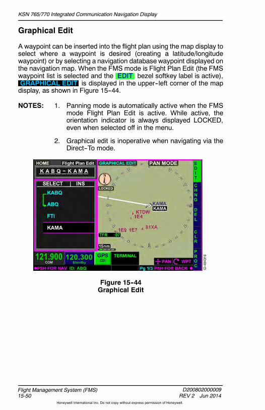
KSN 765/770 Integrated Communication Navigation Display
D200802000009REV 2 Jun 2014
Flight Management System (FMS)15-50
Honeywell International Inc. Do not copy without express permission of Honeywell.
Graphical Edit
A waypoint can be inserted into the flight plan using the map display toselect where a waypoint is desired (creating a latitude/longitudewaypoint) or by selecting a navigation database waypoint displayed onthe navigation map. When the FMS mode is Flight Plan Edit (the FMSwaypoint list is selected and the EDIT bezel softkey label is active),GRAPHICAL EDIT is displayed in the upper--left corner of the mapdisplay, as shown in Figure 15--44.
NOTES: 1. Panning mode is automatically active when the FMSmode Flight Plan Edit is active. While active, theorientation indicator is always displayed LOCKED,even when selected off in the menu.
2. Graphical edit is inoperative when navigating via theDirect--To mode.
Figure 15--44Graphical Edit

KSN 765/770 Integrated Communication Navigation Display
D200802000009REV 2 Jun 2014 15-51
Flight Management System (FMS)
Honeywell International Inc. Do not copy without express permission of Honeywell.
When GRAPHICAL EDIT is displayed, the touchscreen can be usedto select the location of the desired waypoint. When the touchscreenis first pushedwhile not ona flight plan leg, a verticalandhorizontal cyanline centers on the location being touched. A cyan dashed line extendsfrom the last waypoint in the flight plan to the location being touched.Course, distance, ETE, and elevation of where the pilot is touching isdisplayed on theNAVMAP display, as shown in Figure 15--45. Thedatacontinuously updates as the touchscreen location changes.
NOTE: When a navigation database waypoint is selected, thewaypoint name is displayedunder the course, distance, ETE,and elevation field.
Figure 15--45Graphical Edit Data
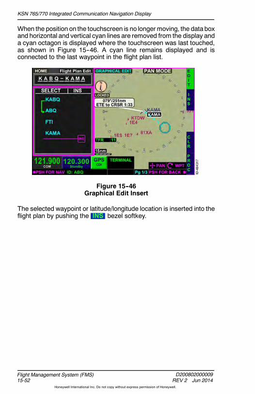
KSN 765/770 Integrated Communication Navigation Display
D200802000009REV 2 Jun 2014
Flight Management System (FMS)15-52
Honeywell International Inc. Do not copy without express permission of Honeywell.
When the position on the touchscreen is no longer moving, the data boxand horizontal and vertical cyan lines are removed from the display anda cyan octagon is displayed where the touchscreen was last touched,as shown in Figure 15--46. A cyan line remains displayed and isconnected to the last waypoint in the flight plan list.
Figure 15--46Graphical Edit Insert
The selected waypoint or latitude/longitude location is inserted into theflight plan by pushing the INS bezel softkey.

KSN 765/770 Integrated Communication Navigation Display
D200802000009REV 2 Jun 2014 15-53
Flight Management System (FMS)
Honeywell International Inc. Do not copy without express permission of Honeywell.
When inserted, the waypoint is appended to the end of the flight planlist. When a navigation database waypoint is selected, the waypointname is inserted into the flight plan. When a location other than anavigation databasewaypoint is selected, a latitude/longitudewaypointis created and displayed as LL followed by a two--digit number( LLXX ), as shown in Figure 15--47.
Figure 15--47Graphical Waypoint Inserted
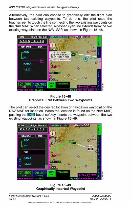
KSN 765/770 Integrated Communication Navigation Display
D200802000009REV 2 Jun 2014
Flight Management System (FMS)15-54
Honeywell International Inc. Do not copy without express permission of Honeywell.
Alternatively, the pilot can choose to graphically edit the flight planbetween two existing waypoints. To do this, the pilot uses thetouchscreen to touch the line connecting the two existing waypoints ontheNAVMAP.When selected, a dashed cyan line extends from the twoexisting waypoints on the NAV MAP, as shown in Figure 15--48.
Figure 15--48Graphical Edit Between Two Waypoints
The pilot can select the desired location or navigation waypoint on theNAV MAP for insertion. When the location is found on the NAV MAP,pushing the INS bezel softkey inserts the waypoint between the twoexisting waypoints, as shown in Figure 15--49.
Figure 15--49Graphically Inserted Waypoint
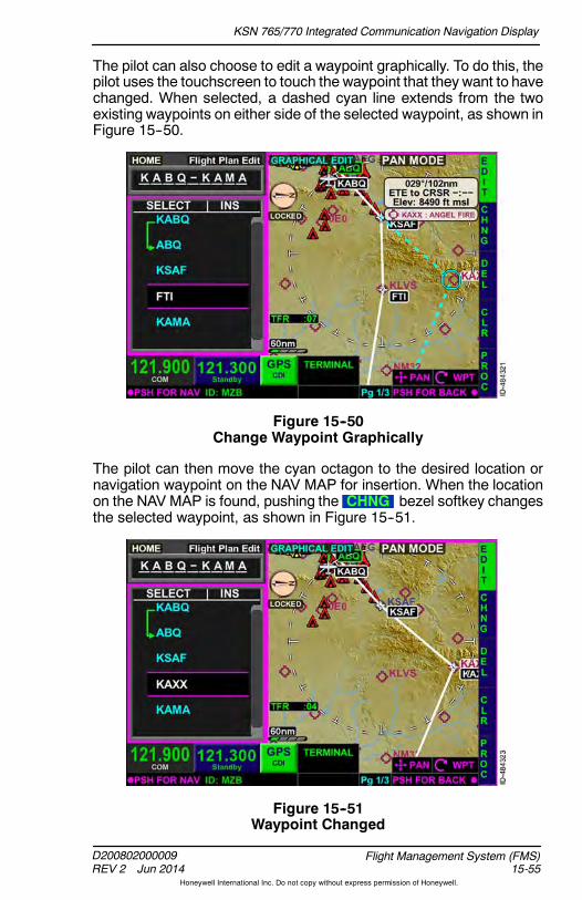
KSN 765/770 Integrated Communication Navigation Display
D200802000009REV 2 Jun 2014 15-55
Flight Management System (FMS)
Honeywell International Inc. Do not copy without express permission of Honeywell.
The pilot can also choose to edit a waypoint graphically. To do this, thepilot uses the touchscreen to touch the waypoint that they want to havechanged. When selected, a dashed cyan line extends from the twoexisting waypoints on either side of the selected waypoint, as shown inFigure 15--50.
Figure 15--50Change Waypoint Graphically
The pilot can then move the cyan octagon to the desired location ornavigation waypoint on the NAV MAP for insertion. When the locationon the NAV MAP is found, pushing the CHNG bezel softkey changesthe selected waypoint, as shown in Figure 15--51.
Figure 15--51Waypoint Changed

KSN 765/770 Integrated Communication Navigation Display
D200802000009REV 2 Jun 2014
Flight Management System (FMS)15-56
Honeywell International Inc. Do not copy without express permission of Honeywell.
Changing or Deleting an Entered Procedure
A previously entered procedure can be changed or deleted using thePROC bezel softkey. To change an arrival, the arrival banner(displayed in green) must be highlighted. To change an approach, themissed approachwaypoint or loaded approach procedure bannermustbe highlighted. To change a departure, no specific waypoint highlight isrequired.
When the PROC bezel softkey is selected, the bezel softkey labels forthe various procedures are displayed. To change or delete a previouslyentered procedure, select the desired bezel softkey. For the exampleflight plan, the approach to 28R is desired to be changed and theAPPR bezel softkey is pushed. The resulting display is shown inFigure 15--52.
Figure 15--52Changing a Procedure
The approach is deleted from the flight plan by selecting theDelete Active Approach prompt and pushing in the joystick knob ortouching the touchscreen twice. To change the approach to a differentapproach, to the same runway, select thedesired approach from the listandpush in the joystick knob.When the joystick knob is pushed in eithersituation, the changes are made to the flight plan.
NOTE: To change the approach to a different runway, the activeapproach must first be deleted before a different runwayapproach can be entered.

KSN 765/770 Integrated Communication Navigation Display
D200802000009REV 2 Jun 2014 15-57
Flight Management System (FMS)
Honeywell International Inc. Do not copy without express permission of Honeywell.
The approach is reinserted into the flight plan by selecting theReinsert prompt and pushing in the joystick knob or touchscreen.When pushed, approach waypoints are reinserted into the flight plan.This can be useful when deleted or sequenced approachwaypoints aredesired again.
A procedure can also be deleted by highlighting the procedure bannerin the flight plan waypoint list and enabling EDIT , as shown inFigure 15--53, and pushing the DEL bezel softkey.
Figure 15--53Delete Procedure

KSN 765/770 Integrated Communication Navigation Display
D200802000009REV 2 Jun 2014
Flight Management System (FMS)15-58
Honeywell International Inc. Do not copy without express permission of Honeywell.
When DEL is pushed, CONFIRM DEL is displayed over theprocedure banner, as shown in Figure 15--54. Pushing the OK bezelsoftkey removes the procedure from the flight plan. Pushing theBACK bezel softkey returns to the previous display.
Figure 15--54Confirm Delete Procedure
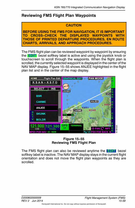
KSN 765/770 Integrated Communication Navigation Display
D200802000009REV 2 Jun 2014 15-59
Flight Management System (FMS)
Honeywell International Inc. Do not copy without express permission of Honeywell.
Reviewing FMS Flight Plan Waypoints
CAUTION
BEFORE USING THE FMS FOR NAVIGATION, IT IS IMPORTANTTO CROSS--CHECK THE DISPLAYED WAYPOINTS WITHTHOSE OF PRINTED DEPARTURE PROCEDURES, EN ROUTECHARTS, ARRIVALS, AND APPROACH PROCEDURES.
The FMS flight plan can be reviewedwaypoint by waypoint by ensuringthe EDIT bezel softkey label is active and using the joystick knob ortouchscreen to scroll through the waypoints. When the flight plan isscrolled, the currently selectedwaypoint is displayed in the center of theNAV MAP display. Figure 15--55 shows ANJEE highlighted in the flightplan list and in the center of the map display.
Figure 15--55Reviewing FMS Flight Plan
The FMS flight plan can also be reviewed anytime the EDIT bezelsoftkey label is inactive. TheNAVMAP display stays in the current flightorientation and does not move the flight plan waypoints as they arescrolled.
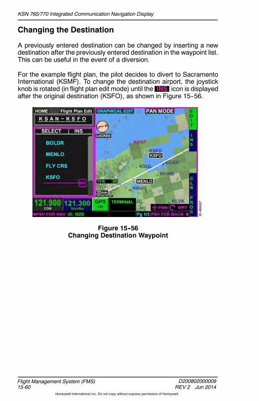
KSN 765/770 Integrated Communication Navigation Display
D200802000009REV 2 Jun 2014
Flight Management System (FMS)15-60
Honeywell International Inc. Do not copy without express permission of Honeywell.
Changing the Destination
A previously entered destination can be changed by inserting a newdestination after the previously entered destination in the waypoint list.This can be useful in the event of a diversion.
For the example flight plan, the pilot decides to divert to SacramentoInternational (KSMF). To change the destination airport, the joystickknob is rotated (in flight plan edit mode) until the INS icon is displayedafter the original destination (KSFO), as shown in Figure 15--56.
Figure 15--56Changing Destination Waypoint

KSN 765/770 Integrated Communication Navigation Display
D200802000009REV 2 Jun 2014 15-61
Flight Management System (FMS)
Honeywell International Inc. Do not copy without express permission of Honeywell.
When the INS bezel softkey is pushed, theINSERT NEW WAYPOINT pop--up window is displayed. The newdestination airport is chosen from the nearest airports list or can bemanually entered using the QWERTY keypad. When the waypoint isinserted into the flight plan, KSMF is displayed after KSFO, as shownin Figure 15--57.
Figure 15--57New Destination Inserted
When the new destination is inserted, the flight plan name is updatedto display the new destination airport, shown as KSMF inFigure 15--57. This is an indication to the pilot the arrival and approachprocedures for the new destination airport can be loaded using thePROC bezel softkey when the HOME window has focus. When theFMS waypoint list has focus, the desired airport will have to behighlighted in order to load an arrival or approach. The pilot can addwaypoints as necessary to the flight plan using normal procedures.
To remove the previous destination and waypoints, a Direct--To can beperformed to awaypoint in the flight plan leading to the newdestination,or theundesiredwaypoints canbe deleted from the flight planmanually.

KSN 765/770 Integrated Communication Navigation Display
D200802000009REV 2 Jun 2014
Flight Management System (FMS)15-62
Honeywell International Inc. Do not copy without express permission of Honeywell.
Changing Flight Plan Waypoints
A previously entered flight plan waypoint can be changed using theCHNG bezel softkey. The desiredwaypoint must be highlighted usingthe joystick knob or touchscreen. Activating the EDIT bezel softkeylabel (if not already selected) ensures the FMS mode isFlight Plan Edit . For the example flight plan, ATC instructs the pilotafter CARME, to fly direct to the Salinas VOR (SNS) instead of ANJEE.Since the ANJEE waypoint needs to be changed, the waypoint ishighlighted on the waypoint list, as shown in Figure 15--58.
Figure 15--58Changing Flight Plan Waypoints
NOTE: While in Flight Plan Edit mode, pushing the desiredwaypoint twice on the touchscreen displays theCHANGE WAYPOINT pop--up window.
Pushing the CHNG bezel softkey displays the nearest airportswaypoint list.

KSN 765/770 Integrated Communication Navigation Display
D200802000009REV 2 Jun 2014 15-63
Flight Management System (FMS)
Honeywell International Inc. Do not copy without express permission of Honeywell.
The CHANGE WAYPOINT pop--upwindow is shown in Figure 15--59.
Figure 15--59Change Current Waypoint
From this page, the pilot can push the bezel softkey in 1R to togglethrough the nearest airports, nearest NAVAIDs, and nearestintersections waypoint list. The pilot can also use the touchscreen toselect the desired waypoint type in the pop--up window header. Usingthe touchscreen to touch the airport identifier area displays theQWERTY keypad, which permits the pilot to manually enter anywaypoint in the navigation database. Selecting the USER bezelsoftkey displays the USER WAYPOINTS pop--up window whichallows the pilot to change a flight plan waypoint to a user--definedwaypoint.
Selecting the OK bezel softkey changes thewaypoint in the flight plan.
NOTE: When a waypoint identifier is selected which has the sameidentifier inmultiple instances in theNAVdatabase, the SELbezel softkey label replaces the OK bezel softkey label.
For the example flight plan, SNS not in the nearest NAVAID waypointlist andmust bemanually entered using theQWERTYkeypad and thenpushing in the joystick knob or OK on the touchscreen.

KSN 765/770 Integrated Communication Navigation Display
D200802000009REV 2 Jun 2014
Flight Management System (FMS)15-64
Honeywell International Inc. Do not copy without express permission of Honeywell.
The new waypoint (SNS) is inserted into the flight plan, replacing theold waypoint (ANJEE), as shown in Figure 15--60. The waypointchanges are also displayed on the map display.
Figure 15--60New Waypoint Inserted

KSN 765/770 Integrated Communication Navigation Display
D200802000009REV 2 Jun 2014 15-65
Flight Management System (FMS)
Honeywell International Inc. Do not copy without express permission of Honeywell.
Deleting Flight Plan Waypoints
When necessary, flight plan waypoints can be deleted from the flightplan list. To delete awaypoint, the desired waypoint is highlighted usingthe joystick knob or touchscreen. Enabling the EDIT bezel softkeylabel (if not already selected) ensures the FMS mode isFlight Plan Edit . For the example flight plan, ATC instructs the pilotafter SKUNK to fly direct to MENLO. This instruction can be compliedwith by deleting the BOLDR waypoint. To delete the BOLDRwaypoint,BOLDR waypoint is highlighted in the waypoint list, as shown inFigure 15--61.
Figure 15--61Deleting Flight Plan Waypoints
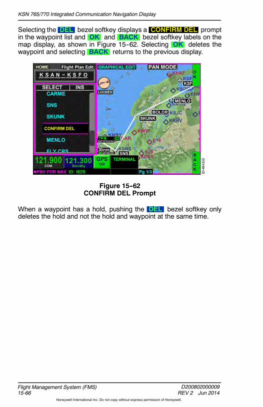
KSN 765/770 Integrated Communication Navigation Display
D200802000009REV 2 Jun 2014
Flight Management System (FMS)15-66
Honeywell International Inc. Do not copy without express permission of Honeywell.
Selecting the DEL bezel softkey displays a CONFIRM DEL promptin the waypoint list and OK and BACK bezel softkey labels on themap display, as shown in Figure 15--62. Selecting OK deletes thewaypoint and selecting BACK returns to the previous display.
Figure 15--62CONFIRM DEL Prompt
When a waypoint has a hold, pushing the DEL bezel softkey onlydeletes the hold and not the hold and waypoint at the same time.
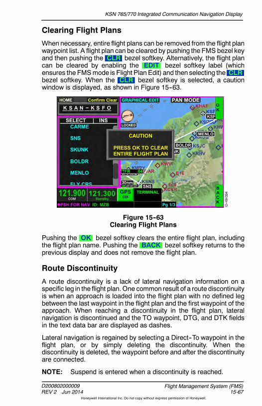
KSN 765/770 Integrated Communication Navigation Display
D200802000009REV 2 Jun 2014 15-67
Flight Management System (FMS)
Honeywell International Inc. Do not copy without express permission of Honeywell.
Clearing Flight Plans
When necessary, entire flight plans can be removed from the flight planwaypoint list. A flight plan can be cleared by pushing the FMS bezel keyand then pushing the CLR bezel softkey. Alternatively, the flight plancan be cleared by enabling the EDIT bezel softkey label (whichensures the FMSmode is Flight Plan Edit) and then selecting the CLRbezel softkey. When the CLR bezel softkey is selected, a cautionwindow is displayed, as shown in Figure 15--63.
Figure 15--63Clearing Flight Plans
Pushing the OK bezel softkey clears the entire flight plan, includingthe flight plan name. Pushing the BACK bezel softkey returns to theprevious display and does not remove the flight plan.
Route Discontinuity
A route discontinuity is a lack of lateral navigation information on aspecific leg in the flight plan.One common result of a route discontinuityis when an approach is loaded into the flight plan with no defined legbetween the last waypoint in the flight plan and the first waypoint of theapproach. When reaching a discontinuity in the flight plan, lateralnavigation is discontinued and the TO waypoint, DTG, and DTK fieldsin the text data bar are displayed as dashes.
Lateral navigation is regained by selecting a Direct--To waypoint in theflight plan, or by simply deleting the discontinuity. When thediscontinuity is deleted, the waypoint before and after the discontinuityare connected.
NOTE: Suspend is entered when a discontinuity is reached.

KSN 765/770 Integrated Communication Navigation Display
D200802000009REV 2 Jun 2014
Flight Management System (FMS)15-68
Honeywell International Inc. Do not copy without express permission of Honeywell.
When necessary, the discontinuity can be removed. To remove thediscontinuity, use the joystick knob or touchscreen to select thediscontinuity, displayed as WPT DISCONNECT Press EDIT/CONNwhen highlighted and is shown in Figure 15--64.
Figure 15--64Route Discontinuity
Activating the EDIT bezel softkey label (when not already selected)ensures the FMS mode is Flight Plan Edit , as shown inFigure 15--64.

KSN 765/770 Integrated Communication Navigation Display
D200802000009REV 2 Jun 2014 15-69
Flight Management System (FMS)
Honeywell International Inc. Do not copy without express permission of Honeywell.
Selecting the CONN bezel softkey displays a CONFIRM CONNprompt in the waypoint list and OK and BACK bezel softkey labelson the map display, as shown in Figure 15--65. Selecting OK deletesthe discontinuity from thewaypoint list. Selecting BACK returns to theprevious display.
Figure 15--65Confirm Connection

KSN 765/770 Integrated Communication Navigation Display
D200802000009REV 2 Jun 2014
Flight Management System (FMS)15-70
Honeywell International Inc. Do not copy without express permission of Honeywell.
Direct--To and Nearest Function
The FMS provides the ability to use Direct--To to godirect to any waypoint. To perform aDirect--To, push theDirect--To bezel key. When pushed, the DIRECT TOpop--up window, shown in Figure 15--66, is displayed.
Figure 15--66Direct--To Pop--Up Window
The DIRECT TO pop--up window defaults to display flight planwaypoints and the FPL bezel softkey label is active (in header and in1R).
A waypoint is chosen from the list using the joystick knob ortouchscreen to highlight the desired Direct--To waypoint. When thedesired Direct--To waypoint is highlighted, the Direct--To is initiated bypushing in the joystick knob or by double tapping the waypoint on thetouchscreen.
NOTE: Anytime a Direct--To is performed, the FMS display isautomatically displayed, even if theDirect--Towas performedwhile on another screen (i.e., NAV MAP or WX page).
Previous waypoints, nearest airports, nearest NAVAIDs and nearestintersections canalsobedisplayed in thenearest waypoint list. Pushingthe bezel softkey at 1R toggles through nearest waypoint groups in thefollowing order:
Flight Plan Waypoint Previous Waypoints Airports NAVAIDs Intersections Repeat

KSN 765/770 Integrated Communication Navigation Display
D200802000009REV 2 Jun 2014 15-71
Flight Management System (FMS)
Honeywell International Inc. Do not copy without express permission of Honeywell.
The various nearest waypoint lists can also be displayed by touchingthe touchscreen buttons in the header field in the DIRECT TO pop--upwindow.
Selecting the PBD (place/bearing/distance) bezel softkey displaysthe TEMP WAYPOINT window, which permits the pilot to create atemporary waypoint used to perform a Direct--To. Creating a temporarywaypoint is described earlier in this section.
Selecting the USER bezel softkey, displayed when the Direct--Tobezel key is pushed, permits the pilot to perform a Direct--To auser--definedwaypoint.When the USER bezel softkey is selected, theUSER WAYPOINTS window, shown in Figure 15--67, is displayed.
Figure 15--67User Waypoints
A user--defined waypoint can be selected from the list or the pilot canchange or addwaypoints to the list. Changing and adding user--definedwaypoints is described later in this section.
The BACK bezel softkey returns to the previous display withoutmaking any changes.

KSN 765/770 Integrated Communication Navigation Display
D200802000009REV 2 Jun 2014
Flight Management System (FMS)15-72
Honeywell International Inc. Do not copy without express permission of Honeywell.
DIRECT--TO UNDO
When a Direct--To is performed to a waypoint that is not part of apublished approach procedure and the waypoint has not beensequenced, an UNDO bezel softkey label is displayed in 3R, as shownin Figure 15--68, when the Direct--To bezel key is pushed.
Figure 15--68Direct--To Undo
When the UNDO bezel softkey is pushed, the active flight plan isrestored to the active flight plan that was available and displayed priorto the selection of the Direct--To function.

KSN 765/770 Integrated Communication Navigation Display
D200802000009REV 2 Jun 2014 15-73
Flight Management System (FMS)
Honeywell International Inc. Do not copy without express permission of Honeywell.
DIRECT--TO A WAYPOINT NOT IN THE FLIGHT PLAN
WhenaDirect--To is performed to awaypoint not contained in theactiveflight plan (APT, NAV, INT, USER, or PREV waypoint), the remainderof the waypoints in the active flight plan are grayed out, as shown inFigure 15--69.
NOTE: Suspend is entered when a Direct--To off path is performed.
Figure 15--69Direct--To a Waypoint Not in the Flight Plan
When the aircraft passes over the Direct--To waypoint not in the FlightPlan, theCDI goes to FROMand theoutbound track is unchanged fromthe inbound track.
There are three options to exit suspend:
1. Execute a direct--to a waypoint in the active flight plan.
2. Add more waypoints to the Direct--To a waypoint not in the flightplan.
3. Push the Direct--To bezel key then push UNDO .

KSN 765/770 Integrated Communication Navigation Display
D200802000009REV 2 Jun 2014
Flight Management System (FMS)15-74
Honeywell International Inc. Do not copy without express permission of Honeywell.
The flight plan can also be resumed when the flight plan waypoint listwindow is active with the EDIT bezel softkey label active. Using thejoystick knob or touchscreen, select a down path waypoint (one of thegrayed waypoints) that is the desired FROM waypoint. The ACTVbezel softkey label is then displayed along the left--side of the display,as shown in Figure 15--70.
Figure 15--70ACTV Softkey Label
Pushing the ACTV bezel softkey displays CONFIRM ACTV over thedesired FROMwaypoint and the OK and BACK bezel softkey labelsare displayed on the right side of the display, as shown in Figure 15--71.
Figure 15--71CONFIRM ACTV

KSN 765/770 Integrated Communication Navigation Display
D200802000009REV 2 Jun 2014 15-75
Flight Management System (FMS)
Honeywell International Inc. Do not copy without express permission of Honeywell.
Pushing the OK bezel softkey activates the selected waypoint as theFROMwaypoint, as shown in Figure 15--72. Pushing the BACK bezelsoftkey returns to the previous display without making any changes.
Figure 15--72FROM Waypoint Activated
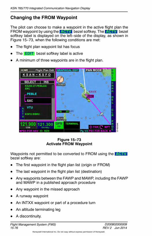
KSN 765/770 Integrated Communication Navigation Display
D200802000009REV 2 Jun 2014
Flight Management System (FMS)15-76
Honeywell International Inc. Do not copy without express permission of Honeywell.
Changing the FROM Waypoint
The pilot can choose to make a waypoint in the active flight plan theFROMwaypoint by using the ACTV bezel softkey. The ACTV bezelsoftkey label is displayed on the left--side of the display, as shown inFigure 15--73, when the following conditions are met:
D The flight plan waypoint list has focus
D The EDIT bezel softkey label is active
D A minimum of three waypoints are in the flight plan.
Figure 15--73Activate FROM Waypoint
Waypoints not permitted to be converted to FROM using the ACTVbezel softkey are:
D The first waypoint in the flight plan list (origin or FROM)
D The last waypoint in the flight plan list (destination)
D Any waypoints between the FAWP andMAWP, including the FAWPand MAWP in a published approach procedure
D Any waypoint in the missed approach
D A runway waypoint
D An INTXX waypoint or part of a procedure turn
D An altitude terminating leg
D A discontinuity.

KSN 765/770 Integrated Communication Navigation Display
D200802000009REV 2 Jun 2014 15-77
Flight Management System (FMS)
Honeywell International Inc. Do not copy without express permission of Honeywell.
During the following conditions, the FROM waypoint cannot bechanged:
D While on the ground
D During an arc turn
D During a radial turn
D During a procedure turn (procedure turn as FROM).
Pushing the ACTV bezel softkey displays CONFIRM ACTV over thedesired FROM waypoint, and the OK and BACK bezel softkeylabels are displayed on the right side of the display. Pushing the OKbezel softkey activates the selected waypoint as the FROM waypoint.Pushing the BACK bezel softkey returns to the previous displaywithout making any changes.
Multiple Database Waypoints With Same Identifier
When a waypoint is entered into the flight plan that has the sameidentifier for multiple published waypoints, the SELECT WAYPOINTpop--up window is displayed, which lists all of the waypoints by name,direct track, distance, and ETE, as shown in Figure 15--74.
Figure 15--74Select Waypoint Pop--Up Window
The joystick knob or touchscreen is used by the pilot to selected theintended waypoint. Pushing in the joystick knob or pushing the OKbezel softkey selects the waypoint. Pushing the BACK bezel softkeyreturns to the previous display without making any changes.

KSN 765/770 Integrated Communication Navigation Display
D200802000009REV 2 Jun 2014
Flight Management System (FMS)15-78
Honeywell International Inc. Do not copy without express permission of Honeywell.
Temporary Waypoint
The TEMP WAYPOINT window is displayed when the PBD bezelsoftkey is pushed (in 1L) from the following pop--up windows:
D Direct--To
D OBS
D Stored Flight Plan Edit
D Change Waypoint
D Insert New Waypoint.
TheTEMPWAYPOINTwindow, shown inFigure 15--75, allows thepilotto create only temporary waypoints and does not allow the pilot tocreate awaypoint for storage in theNAVdatabase. SeeCreating aUserWaypoint later in this section if a custom waypoint is desired to becreated for storage in the NAV database.
Figure 15--75TEMP WAYPOINT
The POS bezel softkey label shown in 2R allows the pilot to enterlatitude and longitude coordinates for the temporary waypoint. TheB/D bezel softkey label in 3R allows the pilot to enter abearing/distance from a NAV database waypoint. The position forlatitude and longitude and bearing/distance can be entered using thejoystick or touchscreen on the NAV MAP. The NRST bezel softkey in4R displays the nearest pop--up window that the user can select thedesired FROM waypoint to be used in a temporary bearing/distancewaypoint. Pushing the OK bezel softkey enters the temporarywaypoint into the flight plan with a preceding asterisk (*).

KSN 765/770 Integrated Communication Navigation Display
D200802000009REV 2 Jun 2014 15-79
Flight Management System (FMS)
Honeywell International Inc. Do not copy without express permission of Honeywell.
FLIGHT PLAN DATA
To the right of the waypoint column is a data column where FMS datacan be alternated for display. Only one column of FMS data can bedisplayed at a time. The column can alternate display by giving focusto the FMS flight plan list and toggling the joystick knob left or right.Figure 15--76 shows ETE data selected for display.
Figure 15--76FMS Data
When thewaypoint list window has focus, pushing the joystick knob leftor right toggles through the FMS data display in the following order:
ETE DTK DTG
Flight plan data is not alternated for display in a continuous loop. Forexample, when ETE is selected for display, pushing the joystick knobto the left does not affect the display, however pushing the joystick tothe right displays DTK.
NOTE: ETE is dashed while on the ground. ETE, DTK, and DTG aredashed when the flight plan contains a discontinuity from thediscontinuity to the end of the flight plan.
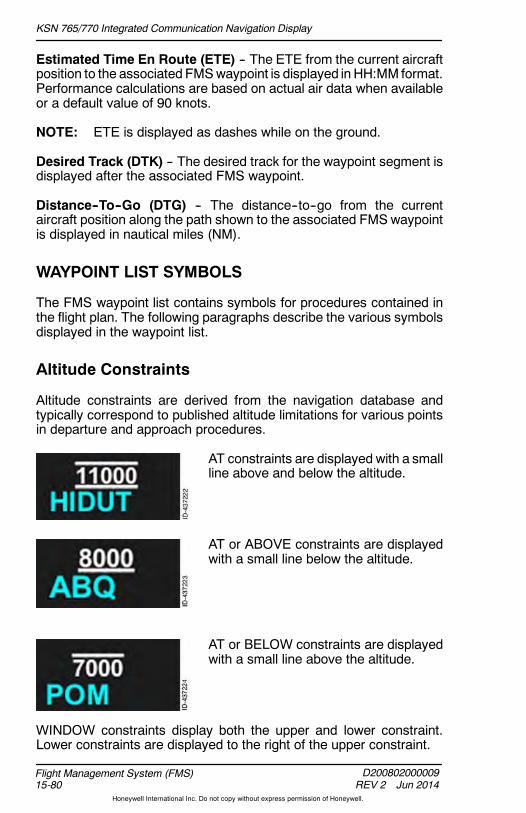
KSN 765/770 Integrated Communication Navigation Display
D200802000009REV 2 Jun 2014
Flight Management System (FMS)15-80
Honeywell International Inc. Do not copy without express permission of Honeywell.
Estimated Time En Route (ETE) -- The ETE from the current aircraftposition to the associated FMSwaypoint is displayed in HH:MM format.Performance calculations are based on actual air data when availableor a default value of 90 knots.
NOTE: ETE is displayed as dashes while on the ground.
Desired Track (DTK) -- The desired track for the waypoint segment isdisplayed after the associated FMS waypoint.
Distance--To--Go (DTG) -- The distance--to--go from the currentaircraft position along the path shown to the associated FMS waypointis displayed in nautical miles (NM).
WAYPOINT LIST SYMBOLS
The FMS waypoint list contains symbols for procedures contained inthe flight plan. The following paragraphs describe the various symbolsdisplayed in the waypoint list.
Altitude Constraints
Altitude constraints are derived from the navigation database andtypically correspond to published altitude limitations for various pointsin departure and approach procedures.
AT constraints are displayed with a smallline above and below the altitude.
AT or ABOVE constraints are displayedwith a small line below the altitude.
AT or BELOW constraints are displayedwith a small line above the altitude.
WINDOW constraints display both the upper and lower constraint.Lower constraints are displayed to the right of the upper constraint.

KSN 765/770 Integrated Communication Navigation Display
D200802000009REV 2 Jun 2014 15-81
Flight Management System (FMS)
Honeywell International Inc. Do not copy without express permission of Honeywell.
Pattern Icons
Pattern icons are used to indicate when a pattern exists on a waypoint.Pattern icons include flyoverwaypoints, holds, arc turns, andprocedureturns.
FlyoverWaypoint Indication -- When awaypoint is a flyover waypoint (ratherthan the more common fly--by waypoint)and a turn must not be commenced priorto flying over the waypoint, a white star
inside of a circle is displayed after the name of the waypoint. Flyoverwaypoints are derived from navigation database loaded proceduresand cannot be entered by the pilot.
Hold Indication -- When a hold isassociated with a waypoint, HLD isdisplayed after the nameof thewaypoint.
Arc Turn Indication -- When a waypointdefines the beginning or end of an arcturn (for example, a DME arc or a radialto a fix), ARC is displayed after thename of the waypoints that define thebeginning and end of the arc turn.
Procedure Turn Indication -- When awaypoint requires a procedure turn, PTis displayed after the name of thewaypoint.
SPECIAL WAYPOINT IDENTIFIERS
Most flight plan legs consist of segments connecting airports, VORs,intersections, or fixes easily and intuitively understood by the pilotbecause they are straight lines (great circles) between two points.
Some flight plan legs are more complex, particularly sequences of legsthat are automatically called up from the navigation database andpopulated into the waypoint list when a pilot chooses a SID, a STAR,or an instrument approach. These legs are sometimes referred to asspecial leg types. The following paragraphs describe the display ofthese types of legs.
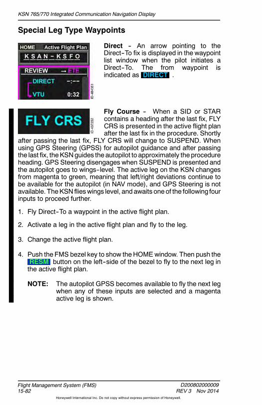
KSN 765/770 Integrated Communication Navigation Display
D200802000009REV 3 Nov 2014
Flight Management System (FMS)15-82
Honeywell International Inc. Do not copy without express permission of Honeywell.
Special Leg Type Waypoints
Direct -- An arrow pointing to theDirect--To fix is displayed in the waypointlist window when the pilot initiates aDirect--To. The from waypoint isindicated as DIRECT .
Fly Course -- When a SID or STARcontains a heading after the last fix, FLYCRS is presented in the active flight planafter the last fix in the procedure. Shortly
after passing the last fix, FLY CRS will change to SUSPEND. Whenusing GPS Steering (GPSS) for autopilot guidance and after passingthe last fix, theKSNguides theautopilot to approximately theprocedureheading. GPS Steering disengages when SUSPEND is presented andthe autopilot goes to wings--level. The active leg on the KSN changesfrom magenta to green, meaning that left/right deviations continue tobe available for the autopilot (in NAV mode), and GPS Steering is notavailable. TheKSN flieswings level, andawaits oneof the following fourinputs to proceed further.
1. Fly Direct--To a waypoint in the active flight plan.
2. Activate a leg in the active flight plan and fly to the leg.
3. Change the active flight plan.
4. Push the FMS bezel key to show theHOMEwindow. Then push theRESM button on the left--side of the bezel to fly to the next leg inthe active flight plan.
NOTE: The autopilot GPSS becomes available to fly the next legwhen any of these inputs are selected and a magentaactive leg is shown.

KSN 765/770 Integrated Communication Navigation Display
D200802000009REV 2 Jun 2014 15-83
Flight Management System (FMS)
Honeywell International Inc. Do not copy without express permission of Honeywell.
Vectors to Final -- The vectors to finalselection provides a final approachextension from the FAWP that can beused to orient the flight crew while beingvectored to the final approach. Vectors tofinal leg is indicated in the flight plan listas FLY VTF .
The VTF bezel softkey label isdisplayed on the left side of the waypointlist when the waypoint list or homewindow is selected and the vectors tofinal approach transition is available.
Pushing the VTF bezel softkey activates the vectors to final function.Suspend is active whenVTF is selectedand thedifference between thecurrent aircraft track and desired aircraft track of the final approachsegment is greater than 45 degrees for more than 3 seconds.
NOTE: To undo vectors to final, reinsert the approach or select adifferent approach.
Initial Approach, Final Approach,and Missed Approach Waypoints --IAWP , FAWP , and MAWPheadings are displayed above the initialapproach waypoint, final approachwaypoint, and missed approachwaypoint, respectively, when anapproach procedure is loaded into theflight plan.
Temporary Waypoints -- Temporarywaypoints are part of a navigationdatabase loaded procedure or can becreated by the pilot. The waypoint isassigned a name that describes how itwas defined and a number (XX). Thename is preceded by an asterisk (*) toindicate a temporary waypoint.Temporary waypoints can occur at ageographically defined latitude/longitude position (LLXX), a placebearing distance (PBDXX), when acourse is intercepted (INTXX), or cansequence when a certain altitude isreached (ALTXX).

KSN 765/770 Integrated Communication Navigation Display
D200802000009REV 2 Jun 2014
Flight Management System (FMS)15-84
Honeywell International Inc. Do not copy without express permission of Honeywell.
Altitude Sequence Legs
Waypoints that sequence when a certain altitude is reached areautomatically sequenced for installations that have an air data input.
For installations that do not have an air data input, the pilot mustmanually sequence each altitude leg. During an altitude sequence leg,altitude sequence instructions are displayed in the center of the screenalong with the RESUME touchscreen button, as shown inFigure 15--77. Selecting the RESUME touchscreen button once thedisplayed altitude has been reached allows the pilot to sequence to thenext leg of the flight plan.
NOTE: Suspend is entered during an altitude sequence leg forinstallations that do not have an air data input until theRESUME touchscreen button is selected.
Figure 15--77Sequence Waypoint
The displayed pop--up window takes over the view and the pilot mustselect the RESUME touchscreen button or bezel softkey to sequencethe altitude legmanually. Other touchscreen functions are inactive untilthe pilot selects the RESUME touchscreen button or bezel softkey.
NOTE: When the pop--up window is displayed, standby radio tuningand swapping can be controlled using the radio controlknob and frequency swap bezel key, and the GPS/VLOCNAV source can be changed using the touchscreen button orthe GPS / VLOC bezel softkey. TheMENUbezel keys arealso available during pop--up annunciations.

KSN 765/770 Integrated Communication Navigation Display
D200802000009REV 3 Nov 2014 15-85
Flight Management System (FMS)
Honeywell International Inc. Do not copy without express permission of Honeywell.
Flight Segments
The following flight segments provide a visual break in the waypoint listfor the pilot and make it more obvious where the different phases offlight begin.
Current Segment -- When autopilotGPSS is available, the currentsegment of the flight plan is indicatedwith a magenta arrow, which showsthe From waypoint and the TOwaypoint. Also, the TO waypoint andactive leg are displayed in magentaon the map display.
When autopilot GPSS is notavailable, the current segment of theflight plan is indicated with a greenarrow that shows the From waypointand the To waypoint. Also, the TOwaypoint and active leg are displayedin green on the map display.
If the GPS position is invalid, thecurrent segment of the flight plan is
indicated with a white arrow. All legs and waypoints on the map displayare shown in white.
Missed Approach -- TheMissed Approach header in thewaypoint list window is used toseparate the flight plan from themissed approach procedure.
Flight Plan Procedure Banner --Loaded procedures in the flight planare displayed in green text prior to thefirst waypoint of the procedure in theflight plan list.
When an LPV or LP approach isselected, the reference path identifieris displayed before the airport name.

KSN 765/770 Integrated Communication Navigation Display
D200802000009REV 2 Jun 2014
Flight Management System (FMS)15-86
Honeywell International Inc. Do not copy without express permission of Honeywell.
Notifications
Notifications are used to warn of conditions that may require attention.
DISCONNECT (Discontinuity) -- Adiscontinuity is a segment in the flightplan where no formal connection is
between one waypoint and the next. A discontinuity does notnecessarily indicate a problem with the flight plan.
FMS HOME WINDOW BEZEL SOFTKEY LABELS
When the FMSwindow has focus, three pages of bezelsoftkey labels can be alternated for display along on theright--side of the display. These bezel softkey labelsallow the pilot to operate various FMS functions.
Not all bezel softkey labels are displayed at all times.For example, OFST is only displayed when an offsetis permitted and LOAD is only displayed when anoff--aircraft flight plan is loaded from the USB port.
Pushing the 1R bezel softkey toggles through the FMSbezel softkey labels in the following order:
1/3 2/3 3/3 Repeat
The following paragraphs describe the bezel softkeylabels displayed when the FMS home window hasfocus.

KSN 765/770 Integrated Communication Navigation Display
D200802000009REV 2 Jun 2014 15-87
Flight Management System (FMS)
Honeywell International Inc. Do not copy without express permission of Honeywell.
Omni Bearing Selector (OBS)
Theomni bearing selector function of theFMSpermits thepilot to selecta waypoint and define a course based off that waypoint to fly. Pushingthe OBS bezel softkey displays the OBS pop--upwindow, which thedesired waypoint can be selected from, as shown in Figure 15--78.
Figure 15--78OBS Waypoint Window
Bezel softkey labels are displayed along the left-- and right--side of thedisplay, which permit the pilot to choose from various types of OBSwaypoints. The pilot can push the bezel softkey in 1R to toggle throughflight plan waypoints, previous flight plan waypoints, nearest airports,NAVAIDs, and intersections. The touchscreen canalso beused to pushthe associated touchscreen buttons displayed in the header.Temporary waypoints can be selected by pushing the PBD bezelsoftkey. User waypoints can be selected by pushing the USER bezelsoftkey. Flight plan waypoints are displayed by default.
For the example flight plan, an OBS is desired in reference to the BigSur (BSR)VOR. The joystick knobor touchscreen canbeused toselectBSR from the flight plan waypoint list. When selected, the OK bezelsoftkey is pushed to activate the OBS function.
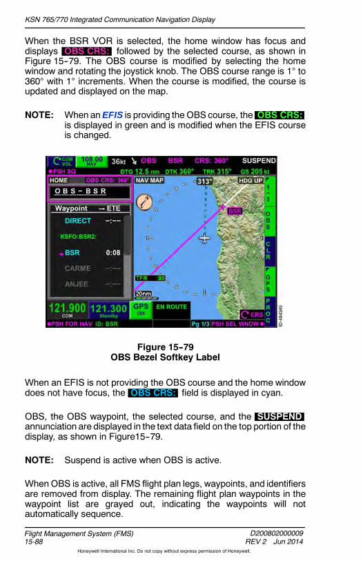
KSN 765/770 Integrated Communication Navigation Display
D200802000009REV 2 Jun 2014
Flight Management System (FMS)15-88
Honeywell International Inc. Do not copy without express permission of Honeywell.
When the BSR VOR is selected, the home window has focus anddisplays OBS CRS: followed by the selected course, as shown inFigure 15--79. The OBS course is modified by selecting the homewindow and rotating the joystick knob. The OBS course range is 1 to360 with 1 increments. When the course is modified, the course isupdated and displayed on the map.
NOTE: When anEFIS is providing the OBS course, the OBS CRS:is displayed in green and is modified when the EFIS courseis changed.
Figure 15--79OBS Bezel Softkey Label
When an EFIS is not providing the OBS course and the home windowdoes not have focus, the OBS CRS: field is displayed in cyan.
OBS, the OBS waypoint, the selected course, and the SUSPENDannunciation are displayed in the text data field on the top portion of thedisplay, as shown in Figure15--79.
NOTE: Suspend is active when OBS is active.
When OBS is active, all FMS flight plan legs, waypoints, and identifiersare removed from display. The remaining flight plan waypoints in thewaypoint list are grayed out, indicating the waypoints will notautomatically sequence.

KSN 765/770 Integrated Communication Navigation Display
D200802000009REV 2 Jun 2014 15-89
Flight Management System (FMS)
Honeywell International Inc. Do not copy without express permission of Honeywell.
The OBS flight plan leg TO the active waypoint is displayed as amagenta line originating from the active waypoint and extending500 NM in the direction that is opposite to the desired track. Forexample, when theOBS course is 360, the magenta line extends fromthe waypoint to 500 NM at a bearing of 180.
The OBS flight plan leg FROM the active waypoint is displayed as awhite line originating from the active waypoint and extending 500 NMin the same direction as the desired track. For example, when theOBScourse is 360, the white line extends from the waypoint to 500 NM ata bearing of 360.
OBS mode is canceled by selecting the OBS bezel softkey andpushing the UNDO bezel softkey shown in Figure 15--80.
Figure 15--80Cancel OBS

KSN 765/770 Integrated Communication Navigation Display
D200802000009REV 2 Jun 2014
Flight Management System (FMS)15-90
Honeywell International Inc. Do not copy without express permission of Honeywell.
Global Positioning System/VOR Localizer(GPS/VLOC)
The GPS or VLOC bezel softkey labels are displayed on theright--side of themap display to indicate theGPSor VOR localizer is thenavigation source. The power--up default is GPS . The currentnavigation source is displayed next to the radio tuning window at alltimes, which continuously displays an indication of the navigationsource even when the FMS 1/3 page of bezel softkey labels are notdisplayed. InFigure 15--81, the current navigation sourcenear the radiotuning window is shown as GPS CDI , which matches the navigationsource selector GPS bezel softkey label.
NOTE: For installations where the EFIS controls the CDI switchingwhen the CDI is set to GPS only during installation, the CDItouchscreen button and GPS / VLOC bezel softkeys arenot displayed.
Figure 15--81GPS Navigation Source

KSN 765/770 Integrated Communication Navigation Display
D200802000009REV 2 Jun 2014 15-91
Flight Management System (FMS)
Honeywell International Inc. Do not copy without express permission of Honeywell.
Pushing the GPS bezel softkey changes the navigation source outputto VOR localizer ( VLOC CDI ) and the bezel softkey label changes toVLOC , as shown in Figure 15--82. CDI CHANGE TO VLOC ismomentarily displaced in the center of the screen when the navigationsource output is switched to VOR localizer.
Figure 15--82VLOC Navigation Source
Pushing the VLOC bezel softkey again changes the bezel softkeylabel back to GPS . CDI CHANGE TO GPS is momentarilydisplaced in the center of the screenwhen the navigation source outputis switched to GPS.

KSN 765/770 Integrated Communication Navigation Display
D200802000009REV 2 Jun 2014
Flight Management System (FMS)15-92
Honeywell International Inc. Do not copy without express permission of Honeywell.
Procedures (PROC)
The PROC bezel softkey label is displayed when the FMS waypointlist windowhas focus orwhen thehomewindowhas focus on page 1/3of the FMS bezel softkey labels. The PROC bezel softkey is used toaccess departure, arrival, approach, and hold procedures. Departure,arrival, and approach procedures are described earlier in this section.Holding procedures are described in the following paragraphs.
When a waypoint in the flight plan (which is not the FROM waypoint)is highlighted and the PROC bezel softkey label is active, the HOLDbezel softkey label is displayed in 2L, as shown in Figure 15--83.
Figure 15--83PROC Bezel Softkey Label
Holding
Three types of holding patterns existwithin the FMS. The high altitude (HA)holding pattern terminates at a specificaltitude. The hold to a manualtermination (HM) holding pattern
requires a manual termination. The hold to a fix (HF) holding patternterminates when a single circuit in the hold has been completed, suchas a teardrop entry into the hold. The FMS determines the type of holdbeing executed and is responsible for theproper execution of theholds.The waypoint list displays a white HLD for all holding procedures.
NOTE: ETA for waypoints following a hold with a manual terminationare calculated based on one turn in holding then continuingon flight plan.

KSN 765/770 Integrated Communication Navigation Display
D200802000009REV 2 Jun 2014 15-93
Flight Management System (FMS)
Honeywell International Inc. Do not copy without express permission of Honeywell.
The actual path followed during the hold entry is depicted on the map.TheFMSdetermines the typeof entry to use in order to keep theaircraftin the protected area of the hold and minimize aircraft maneuveringduring the entry process.
When a teardropor parallel entry is chosen by the FMS, the aircraft fliesover the holding fix and then continues away until reaching the point atwhich a turn that results in a 45 intercept angle is commenced.
The length of the outbound leg varies based on groundspeed, turnradius required to achieve a 45 intercept angle on completion of theturn, and allowance made for the final turn necessary to intercept theinbound holding course.
A hold must be defined at a navigation database waypoint (includingcustom waypoints). A hold cannot be defined at a missed approachwaypoint (MAWP) or runway waypoint (RWY). When a hold at a flightplanwaypoint is desired, thewaypoint windowmust be selectedand thedesired waypoint highlighted. Figure 15--84 shows the waypoint listwindow selected and the VTU VOR highlighted.
Figure 15--84HOLD Bezel Softkey Label

KSN 765/770 Integrated Communication Navigation Display
D200802000009REV 2 Jun 2014
Flight Management System (FMS)15-94
Honeywell International Inc. Do not copy without express permission of Honeywell.
Pushing the HOLD bezel softkey displays ADD and BACK bezelsoftkey labels, as shown in Figure 15--85.
Figure 15--85Add a Hold
When the ADD bezel softkey is pushed, the Modify Parameterswindow, shown in Figure 15--86, is displayed. When a hold is notpublished at the selected waypoint, the inbound course defaults to theflight plan course leading to the waypoint.
Figure 15--86Modify Hold Parameters

KSN 765/770 Integrated Communication Navigation Display
D200802000009REV 2 Jun 2014 15-95
Flight Management System (FMS)
Honeywell International Inc. Do not copy without express permission of Honeywell.
The Modify Parameters window permits the pilot to define theinbound course of the hold, either the leg time or distance, whichdirection turns are made, and at what speed the aircraft holds.
When a hold is published at a selected waypoint, the FMS usesinformation contained in the NAV database to pre--populate the holdparameters with the published hold. The NAV database can containpublishedhold information for awaypoint suchascourse, turndirection,leg length, and speed. The Modify Parameters window is used toverify these presumed intentions of published holding patterns arecorrect. The pilot may change any or all of the pre--populated data asdesired using the joystick and touchscreen. When published, holdspecifications are modified, the PUB bezel softkey label is displayed.Pushing the PUB bezel softkey populates fields with publishedvalues.
The waypoint highlighted in the waypoint list when the HOLD bezelsoftkey is pushed is the waypoint the Modify Parameters window isbased on. The selected hold waypoint is displayed on the top of theModify Parameters window.
Pushing the OK bezel softkey inserts the hold into the flight plan andcloses the Modify Parameters window. Pushing the BACK bezelsoftkey returns to the previous display without saving any changes.
When a published hold exists, the default values are from the NAVdatabase for the published holding procedure. TheModify Parameters window for non--published holds is described inthe following paragraphs.
D Course -- The inbound course to the hold waypoint is displayed andcan be modified using the joystick knob.
D Turn Dir -- Left/Right -- The turn direction of the holding pattern isselected here. The default selection is right and can be modifiedusing the joystick knob.
D Leg Unit -- Time/Dist -- The desired hold length can be alteredbetween Time and Dist (distance). The default selection is time.When time is selected, the Leg Time header is displayed underthe Leg Unit header, as shown in Figure 15--86. When distance isselected, the Leg Dist header is displayed under the Leg Unitheader.
D Leg Time -- The leg time field permits the pilot to input the leg timein minutes. The FMS default value for leg time is 1 minute below14,000 feet MSL and 1.5 minutes at or above 14,000 feet MSL. TheFMS uses the current altitude of the aircraft when determiningaltitude.
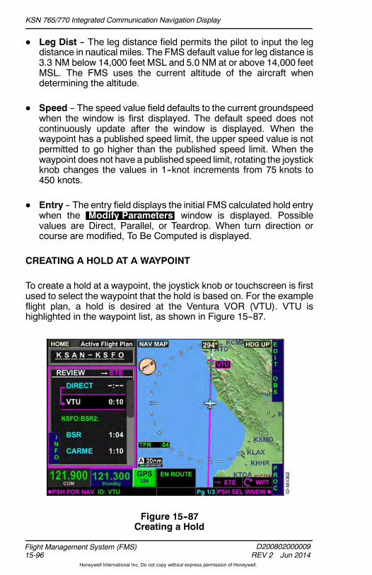
KSN 765/770 Integrated Communication Navigation Display
D200802000009REV 2 Jun 2014
Flight Management System (FMS)15-96
Honeywell International Inc. Do not copy without express permission of Honeywell.
D Leg Dist -- The leg distance field permits the pilot to input the legdistance in nautical miles. The FMS default value for leg distance is3.3 NM below 14,000 feet MSL and 5.0 NM at or above 14,000 feetMSL. The FMS uses the current altitude of the aircraft whendetermining the altitude.
D Speed -- The speed value field defaults to the current groundspeedwhen the window is first displayed. The default speed does notcontinuously update after the window is displayed. When thewaypoint has a published speed limit, the upper speed value is notpermitted to go higher than the published speed limit. When thewaypoint does not have a published speed limit, rotating the joystickknob changes the values in 1--knot increments from 75 knots to450 knots.
D Entry -- The entry field displays the initial FMS calculated hold entrywhen the Modify Parameters window is displayed. Possiblevalues are Direct, Parallel, or Teardrop. When turn direction orcourse are modified, To Be Computed is displayed.
CREATING A HOLD AT A WAYPOINT
To create a hold at a waypoint, the joystick knob or touchscreen is firstused to select the waypoint that the hold is based on. For the exampleflight plan, a hold is desired at the Ventura VOR (VTU). VTU ishighlighted in the waypoint list, as shown in Figure 15--87.
Figure 15--87Creating a Hold

KSN 765/770 Integrated Communication Navigation Display
D200802000009REV 2 Jun 2014 15-97
Flight Management System (FMS)
Honeywell International Inc. Do not copy without express permission of Honeywell.
When the PROC bezel softkey is pushed, the HOLD bezel softkeylabel is displayed, as shown in Figure 15--88.
Figure 15--88HOLD Bezel Softkey Label
When the HOLD bezel softkey is pushed, the ADD bezel softkeylabel is displayed, as shown in Figure 15--89.
Figure 15--89ADD Bezel Softkey Label

KSN 765/770 Integrated Communication Navigation Display
D200802000009REV 2 Jun 2014
Flight Management System (FMS)15-98
Honeywell International Inc. Do not copy without express permission of Honeywell.
When the ADD bezel softkey is pushed, the Modify Parameterswindow, shown in Figure 15--90, is displayed. In this window, the pilotcanmodify thehold parameters by toggling the joystick knobupordownto the desired field or using the touchscreen to select the desired field.When the desired field is selected, the joystick knob can be rotated toset the desired parameter. For the example flight plan, an inboundcourse of 180 degrees, right--hand turns, and 1.5--minute legs isdesired.
Figure 15--90Hold Settings Window
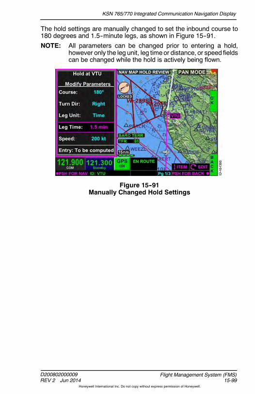
KSN 765/770 Integrated Communication Navigation Display
D200802000009REV 2 Jun 2014 15-99
Flight Management System (FMS)
Honeywell International Inc. Do not copy without express permission of Honeywell.
The hold settings are manually changed to set the inbound course to180 degrees and 1.5--minute legs, as shown in Figure 15--91.
NOTE: All parameters can be changed prior to entering a hold,however only the leg unit, leg timeor distance, or speed fieldscan be changed while the hold is actively being flown.
Figure 15--91Manually Changed Hold Settings
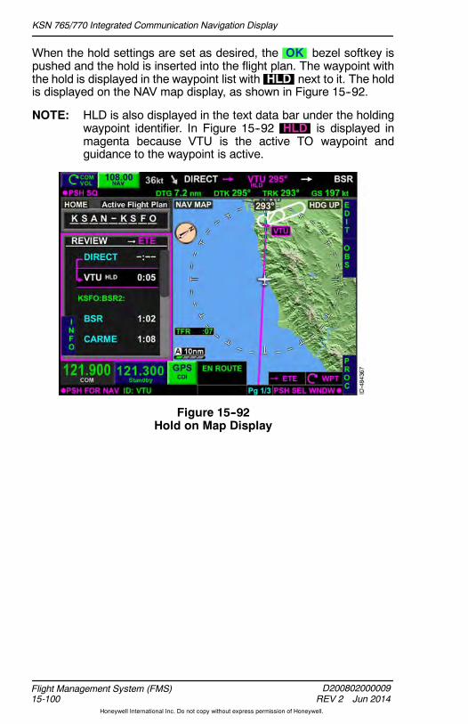
KSN 765/770 Integrated Communication Navigation Display
D200802000009REV 2 Jun 2014
Flight Management System (FMS)15-100
Honeywell International Inc. Do not copy without express permission of Honeywell.
When the hold settings are set as desired, the OK bezel softkey ispushed and the hold is inserted into the flight plan. The waypoint withthe hold is displayed in the waypoint list with HLD next to it. The holdis displayed on the NAV map display, as shown in Figure 15--92.
NOTE: HLD is also displayed in the text data bar under the holdingwaypoint identifier. In Figure 15--92 HLD is displayed inmagenta because VTU is the active TO waypoint andguidance to the waypoint is active.
Figure 15--92Hold on Map Display
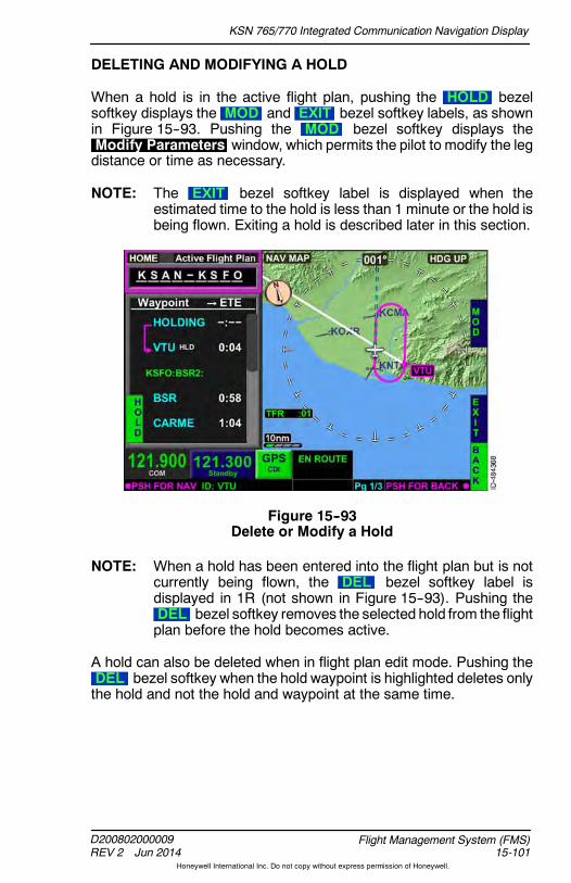
KSN 765/770 Integrated Communication Navigation Display
D200802000009REV 2 Jun 2014 15-101
Flight Management System (FMS)
Honeywell International Inc. Do not copy without express permission of Honeywell.
DELETING AND MODIFYING A HOLD
When a hold is in the active flight plan, pushing the HOLD bezelsoftkey displays the MOD and EXIT bezel softkey labels, as shownin Figure 15--93. Pushing the MOD bezel softkey displays theModify Parameters window, which permits the pilot to modify the legdistance or time as necessary.
NOTE: The EXIT bezel softkey label is displayed when theestimated time to the hold is less than 1 minute or the hold isbeing flown. Exiting a hold is described later in this section.
Figure 15--93Delete or Modify a Hold
NOTE: When a hold has been entered into the flight plan but is notcurrently being flown, the DEL bezel softkey label isdisplayed in 1R (not shown in Figure 15--93). Pushing theDEL bezel softkey removes the selected hold from the flightplan before the hold becomes active.
A hold can also be deleted when in flight plan edit mode. Pushing theDEL bezel softkey when the hold waypoint is highlighted deletes onlythe hold and not the hold and waypoint at the same time.
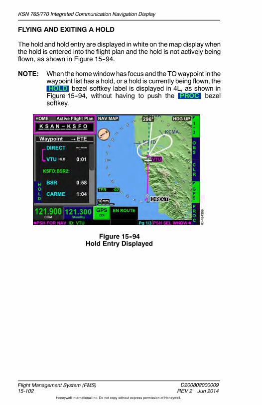
KSN 765/770 Integrated Communication Navigation Display
D200802000009REV 2 Jun 2014
Flight Management System (FMS)15-102
Honeywell International Inc. Do not copy without express permission of Honeywell.
FLYING AND EXITING A HOLD
The hold and hold entry are displayed in white on themap display whenthe hold is entered into the flight plan and the hold is not actively beingflown, as shown in Figure 15--94.
NOTE: When thehomewindowhas focus and the TOwaypoint in thewaypoint list has a hold, or a hold is currently being flown, theHOLD bezel softkey label is displayed in 4L, as shown inFigure 15--94, without having to push the PROC bezelsoftkey.
Figure 15--94Hold Entry Displayed
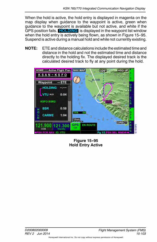
KSN 765/770 Integrated Communication Navigation Display
D200802000009REV 2 Jun 2014 15-103
Flight Management System (FMS)
Honeywell International Inc. Do not copy without express permission of Honeywell.
When the hold is active, the hold entry is displayed in magenta on themap display when guidance to the waypoint is active, green whenguidance to the waypoint is available but not active, and white if theGPS position fails. HOLDING is displayed in the waypoint list windowwhen the hold entry is actively being flown, as shown in Figure 15--95.Suspend is active during amanual hold andwhile not currently existing.
NOTE: ETEanddistance calculations include theestimated timeanddistance in the hold and not the estimated time and distancedirectly to the holding fix. The displayed desired track is thecalculated desired track to fly at any point during the hold.
Figure 15--95Hold Entry Active
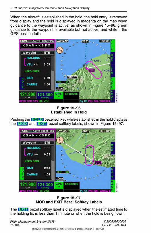
KSN 765/770 Integrated Communication Navigation Display
D200802000009REV 2 Jun 2014
Flight Management System (FMS)15-104
Honeywell International Inc. Do not copy without express permission of Honeywell.
When the aircraft is established in the hold, the hold entry is removedfrom display and the hold is displayed in magenta on the map whenguidance to the waypoint is active, as shown in Figure 15--96, greenguidance to the waypoint is available but not active, and white if theGPS position fails.
Figure 15--96Established in Hold
Pushing the HOLD bezel softkeywhile established in theholddisplaysthe MOD and EXIT bezel softkey labels, shown in Figure 15--97.
Figure 15--97MOD and EXIT Bezel Softkey Labels
The EXIT bezel softkey label is displayed when the estimated time tothe holding fix is less than 1 minute or when the hold is being flown.

KSN 765/770 Integrated Communication Navigation Display
D200802000009REV 2 Jun 2014 15-105
Flight Management System (FMS)
Honeywell International Inc. Do not copy without express permission of Honeywell.
When the EXIT bezel softkey is pushed, the aircraft is less than1 minute from the holding fix, and the hold is not being flown, the holdon the TO waypoint is deleted and the remainder of the flight plan isflown.
When the EXIT bezel softkey is pushed and the aircraft is active in thefirst turn or the outbound leg, the holding pattern is truncated byshortening the outbound leg. The shortened outbound leg is createdlong enough to allow for a curved path transition back to the holding fix.The inbound leg of the hold is displayed in magenta when guidance tothewaypoint is active, greenwhenguidance to thewaypoint is availablebut not active, and white if the GPS position fails. The rest of the holdis displayed in white, as shown in Figure 15--98.
Figure 15--98Exiting A Hold
When the aircraft is on turn two of the holding pattern (turning inbound)or on the inbound leg, the holding pattern is unable to be truncated asthe most direct path to the holding fix is already active. The aircraftcontinues on the normal holding pattern path until sequencing theholding fix. The entire holding pattern remains displayed in magentawhen guidance to the waypoint is active, green when guidance to thewaypoint is available but not active, and white if the GPS position fails.
The holding pattern is truncated for direct hold entries and establishedholding patterns. When the EXIT bezel softkey is pushed during ateardrop or parallel holding entry, the entry is flown completely and thehold is exited when approaching the holding fix.
When the holding fix is reached, the FMS then continues via the flightplan. EXIT HOLD is displayed in the waypoint list window to indicateto the pilot the hold will be exited when the hold waypoint is sequenced.

KSN 765/770 Integrated Communication Navigation Display
D200802000009REV 2 Jun 2014
Flight Management System (FMS)15-106
Honeywell International Inc. Do not copy without express permission of Honeywell.
Pushing the MOD bezel softkey during a hold displays theModify Parameters window, which allows the pilot to modify the legdistance or time.When the holding procedure is actively flown, only thehold leg distance or time can bemodified. TheFMSmessageUNABLEHOLDCHANGE is displayedwhenanythingother than the legdistanceor time is attempted to be changed while in the holding pattern.
The RESM bezel softkey label is displayed when the aircraft is in theprocess of exiting the holding pattern. Pushing the RESM bezelsoftkey results in the FMS resuming the holding pattern currently beingexited.
The FMS message EXITING HOLD is displayed when the holdtermination altitude has been reached and the hold is automaticallyexiting.

KSN 765/770 Integrated Communication Navigation Display
D200802000009REV 2 Jun 2014 15-107
Flight Management System (FMS)
Honeywell International Inc. Do not copy without express permission of Honeywell.
Offsets
Offsets permit the pilot to enter a parallel offset course either left or rightof the flight planpath. Offsets are entered into the flight planbyselectingthe OFST bezel softkey on the 2/3 page of the bezel softkeys on themap, shown in Figure 15--99.
Figure 15--99Offset Bezel Softkey Label
When the OFST bezel softkey is selected, theOFFSET FLIGHT PLAN window, shown in Figure 15--100, isdisplayed.
Figure 15--100Flight Plan Offset

KSN 765/770 Integrated Communication Navigation Display
D200802000009REV 2 Jun 2014
Flight Management System (FMS)15-108
Honeywell International Inc. Do not copy without express permission of Honeywell.
Offset values are entered into the OFFSET FLIGHT PLAN windowbyrotating the joystick knob. Rotating the joystick knob to the leftincreases offset values to the left of course. Rotating the joystick knobto the right increases offset values to the right of course. Offset valueshave a valid range of 1 to 30 NM in 1NM increments. When the desiredoffset value is displayed, pushing the OK bezel softkey enters theoffset into the flight plan. Pushing the BACK bezel softkey returns tothe previous display without entering the offset.
For the example flight plan, an offset is desired 5 NM to the right ofcourse. The joystick knob is rotated to the right until 5 nm Right isdisplayed, as shown in Figure 15--101. The offset is entered into theflight plan by pushing the OK bezel softkey.
Figure 15--101Entering Offset Into Flight Plan

KSN 765/770 Integrated Communication Navigation Display
D200802000009REV 2 Jun 2014 15-109
Flight Management System (FMS)
Honeywell International Inc. Do not copy without express permission of Honeywell.
When the offset is entered into the flight plan, OFST followed by thedistance and left or right of course is displayed in the text data bar, asshown in Figure 15--102. The OFST annunciation and the OFSTbezel softkey label being active indicates that an offset is active.
Figure 15--102FP Offset
The course deviation indicator (CDI) on the FMS track bar in the HSImoves to the right or left (as appropriate) to indicate the aircraft mustbe flown to the left or right in order to achieve the applied offset. Whenthe CDI becomes centered, the aircraft is offset the desired distance.
The aircraft symbol on the map is then depicted to the right or left (asappropriate) of the active flight plan leg. The offset course is notdepicted on the map display.
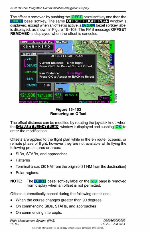
KSN 765/770 Integrated Communication Navigation Display
D200802000009REV 2 Jun 2014
Flight Management System (FMS)15-110
Honeywell International Inc. Do not copy without express permission of Honeywell.
Theoffset is removedby pushing the OFST bezel softkey and then theCNCL bezel softkey. The same OFFSET FLIGHT PLAN window isdisplayed, except whenan offset is active, a CNCL bezel softkey labelis displayed, as shown in Figure 15--103. The FMS messageOFFSETREMOVED is displayed when the offset is canceled.
Figure 15--103Removing an Offset
The offset distance can be modified by rotating the joystick knob whenthe OFFSET FLIGHT PLAN window is displayed andpushing OK toenter the modification.
Offsets are applied to the flight plan while in the en route, oceanic, orremote phase of flight, however they are not available while flying thefollowing procedures or areas:
D SIDs, STARs, and approaches
D Patterns
D Terminal areas (30NM from theorigin or31NMfrom thedestination)
D Polar regions.
NOTE: The OFST bezel softkey label on the 2/3 page is removedfrom display when an offset is not permitted.
Offsets automatically cancel during the following conditions:
D When the course changes greater than 90 degrees
D On commencing SIDs, STARs, and approaches
D On commencing intercepts.

KSN 765/770 Integrated Communication Navigation Display
D200802000009REV 2 Jun 2014 15-111
Flight Management System (FMS)
Honeywell International Inc. Do not copy without express permission of Honeywell.
Search (SRCH)
The search function of the FMS permits thepilot to enter any navigationdatabase waypoint and display the waypoint in the navigation mapwindow. Pushing the SRCH bezel softkey in 3R, shown inFigure 15--104, displays a QWERTY keypad from which the pilot canenter the desired navigation database waypoint.
Figure 15--104Search Function

KSN 765/770 Integrated Communication Navigation Display
D200802000009REV 2 Jun 2014
Flight Management System (FMS)15-112
Honeywell International Inc. Do not copy without express permission of Honeywell.
The QWERTY keypad is shown in Figure 15--105. For this exampleflight plan, the pilot wants to display Los Angeles Airport (KLAX) in thenavigation map view and display additional information about theairport. The navigation database waypoint is entered using the joystickknob or touchscreen and pushing in the joystick knob or by pushingOK on the QWERTY keypad.
Figure 15--105QWERTY Search
When entered, the navigation map view is automatically displayedwiththe selected waypoint in the center of the navigation map, as shown inFigure 15--106.
Figure 15--106Search Navigation Map View
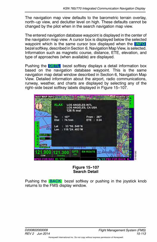
KSN 765/770 Integrated Communication Navigation Display
D200802000009REV 2 Jun 2014 15-113
Flight Management System (FMS)
Honeywell International Inc. Do not copy without express permission of Honeywell.
The navigation map view defaults to the barometric terrain overlay,north--up view, and declutter level on high. These defaults cannot bechanged by the pilot when in the search navigation map view.
The entered navigation database waypoint is displayed in the center ofthe navigation map view. A cursor box is displayed below the selectedwaypoint which is the same cursor box displayed when the INFObezel softkey, described inSection 6, NavigationMapView, is selected.Information such as magnetic course, distance, ETE, elevation, andtype of approaches (when available) are displayed.
Pushing the DETL bezel softkey displays a detail information boxbased on the navigation database waypoint. This is the samenavigation map detail window described in Section 6, Navigation MapView. Detailed information about the airport, radio communications,runway, weather, and charts are displayed by selecting any of theright--side bezel softkey labels displayed in Figure 15--107.
Figure 15--107Search Detail
Pushing the BACK bezel softkey or pushing in the joystick knobreturns to the FMS display window.

KSN 765/770 Integrated Communication Navigation Display
D200802000009REV 2 Jun 2014
Flight Management System (FMS)15-114
Honeywell International Inc. Do not copy without express permission of Honeywell.
Off--Aircraft Created Flight Plan (Future Option)
The pilot has the option to load an off--aircraft created flight plan insteadof creating a new flight plan on the aircraft. The flight plans createdoff--aircraft use a .fpl (flight plan) file extension. Each created flight planis saved as an individual .fpl file and only one flight plan can be loadedon a USB flash drive at a time.
With the aircraft on the ground, theUSB flash drive can be inserted intothe USB slot in the front of the unit. When the USB flash drive with aflight plan is inserted, the LOAD bezel softkey label at 4R is displayed,shown in Figure 15--108.
Figure 15--108LOAD Bezel Softkey Label
CAUTION
USE OF THE USB PORT IN FLIGHT IS NOT AUTHORIZED ANDCAN CAUSE A RESET.
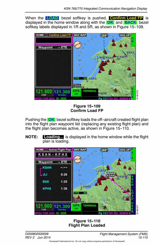
KSN 765/770 Integrated Communication Navigation Display
D200802000009REV 2 Jun 2014 15-115
Flight Management System (FMS)
Honeywell International Inc. Do not copy without express permission of Honeywell.
When the LOAD bezel softkey is pushed, Confirm Load FP isdisplayed in the home window along with the OK and BACK bezelsoftkey labels displayed in 1R and 5R, as shown in Figure 15--109.
Figure 15--109Confirm Load FP
Pushing the OK bezel softkey loads the off--aircraft created flight planinto the flight plan waypoint list (replacing any existing flight plan) andthe flight plan becomes active, as shown in Figure 15--110.
NOTE: Loading... is displayed in the home window while the flightplan is loading.
Figure 15--110Flight Plan Loaded
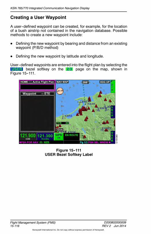
KSN 765/770 Integrated Communication Navigation Display
D200802000009REV 2 Jun 2014
Flight Management System (FMS)15-116
Honeywell International Inc. Do not copy without express permission of Honeywell.
Creating a User Waypoint
A user--defined waypoint can be created, for example, for the locationof a bush airstrip not contained in the navigation database. Possiblemethods to create a new waypoint include:
D Defining the new waypoint by bearing and distance from an existingwaypoint (P/B/D method)
D Defining the new waypoint by latitude and longitude.
User--defined waypoints are entered into the flight plan by selecting theUSER bezel softkey on the 2/3 page on the map, shown inFigure 15--111.
Figure 15--111USER Bezel Softkey Label

KSN 765/770 Integrated Communication Navigation Display
D200802000009REV 2 Jun 2014 15-117
Flight Management System (FMS)
Honeywell International Inc. Do not copy without express permission of Honeywell.
When the USER bezel softkey is pushed, the USER WAYPOINTSpop--up window, shown in Figure 15--112, is displayed.
Figure 15--112USER WAYPOINTS Window
In this window, the pilot can add, change, and delete user waypoints.The pilot can also delete all waypoints contained in the customdatabase.
NOTE: At least one custom waypoint must be stored for the CLR ,CHNG , or DEL bezel softkey labels to be displayed.

KSN 765/770 Integrated Communication Navigation Display
D200802000009REV 2 Jun 2014
Flight Management System (FMS)15-118
Honeywell International Inc. Do not copy without express permission of Honeywell.
A custom user waypoint is added by pushing the ADD bezel softkey.When the ADD bezel softkey is pushed, a USER WAYPOINTwindow, shown in Figure 15--113, is displayed, which permits the pilotto define the custom waypoint. The pilot can define a custom waypointby using latitude/longitude or bearing/distance. The default display islatitude/longitude with the current aircraft position.
Figure 15--113USER WAYPOINT
Any combination of 5 letters and numbers can be used to define acustomwaypoint name. The joystick knob can be rotated to change theletters and numbers in the IDENT field or the QWERTY keypad canbe displayed by touching the IDENT field on the touchscreen.
NOTE: When the identifier used to name the new waypoint alreadyexists in the navigation database, the new waypoint isinserted as a custom waypoint, replacing the previouslydefined waypoint.
Pushing in on the joystick knob toggles to the NAVMAP display. Whenthe NAV MAP has focus, the joystick knob can be used to pan or thetouchscreen can be used to select a user waypoint.
For the example flight plan, a custom waypoint is to be defined at32 degrees, 32 minutes North and 123 degrees, 20 minutes South.MYWPT is the desired custom waypoint name.

KSN 765/770 Integrated Communication Navigation Display
D200802000009REV 2 Jun 2014 15-119
Flight Management System (FMS)
Honeywell International Inc. Do not copy without express permission of Honeywell.
The joystick knob or touchscreen can be used to enter the desiredwaypoint name in the IDENT field. After the custom waypoint name isdefined, the cursor can be moved to the latitude field by pushing downon the joystick knob or using the touchscreen. The joystick knob canthen be rotated and pushed left or right until the desired latitude isdefined or the touchscreen can be used to select the desired locationon the map display. Figure 15--114 shows the data entered for theexample flight plan.
NOTE: The waypoint name is displayed on the map display.
Figure 15--114Custom User Waypoint
The PPOS bezel softkey can be used to enter the present aircraftposition in the LAT and LON fields to be used as a user waypoint.
When the desired waypoint name and latitude/longitude are entered inthe USER WAYPOINT field, as shown in Figure 15--114, thewaypointis entered into the custom waypoint list by pushing the OK bezelsoftkey. Pushing the BACK bezel softkey returns to the previous pagewithout saving any waypoint data.

KSN 765/770 Integrated Communication Navigation Display
D200802000009REV 2 Jun 2014
Flight Management System (FMS)15-120
Honeywell International Inc. Do not copy without express permission of Honeywell.
When entered, the USER WAYPOINTS pop--up window is displayedwith the newly defined waypoint displayed, as shown in Figure 15--115.Since the new waypoint was defined using latitude/longitude, thecoordinates are displayed next to the waypoint name.
Figure 15--115New User Waypoint
The new waypoint can now be used as any other waypoint containedin the navigation database.

KSN 765/770 Integrated Communication Navigation Display
D200802000009REV 2 Jun 2014 15-121
Flight Management System (FMS)
Honeywell International Inc. Do not copy without express permission of Honeywell.
A custom waypoint can also be created using bearing/distance from adatabase waypoint. When the USER WAYPOINTS window isdisplayed, select the B/D bezel softkey, shown in 3R inFigure 15--116.
Figure 15--116Bearing/Distance
When the B/D bezel softkey label is active, the USER WAYPOINTwindow data fields change from LAT and LON to FROM , BRG ,and DIST , as shown in Figure 15--117.
Figure 15--117FROM/BRG/DIST
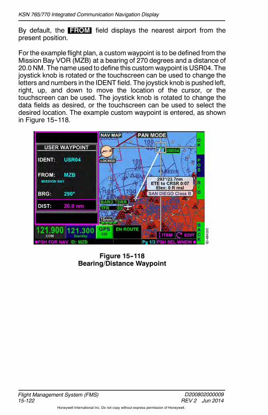
KSN 765/770 Integrated Communication Navigation Display
D200802000009REV 2 Jun 2014
Flight Management System (FMS)15-122
Honeywell International Inc. Do not copy without express permission of Honeywell.
By default, the FROM field displays the nearest airport from thepresent position.
For the example flight plan, a customwaypoint is to be defined from theMission Bay VOR (MZB) at a bearing of 270 degrees and a distance of20.0 NM. The nameused to define this customwaypoint is USR04. Thejoystick knob is rotated or the touchscreen can be used to change theletters and numbers in the IDENT field. The joystick knob is pushed left,right, up, and down to move the location of the cursor, or thetouchscreen can be used. The joystick knob is rotated to change thedata fields as desired, or the touchscreen can be used to select thedesired location. The example custom waypoint is entered, as shownin Figure 15--118.
Figure 15--118Bearing/Distance Waypoint
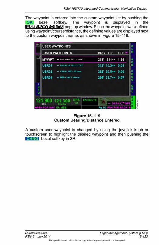
KSN 765/770 Integrated Communication Navigation Display
D200802000009REV 2 Jun 2014 15-123
Flight Management System (FMS)
Honeywell International Inc. Do not copy without express permission of Honeywell.
The waypoint is entered into the custom waypoint list by pushing theOK bezel softkey. The waypoint is displayed in theUSER WAYPOINTS pop--upwindow. Since thewaypoint was definedusingwaypoint/course/distance, the defining values are displayed nextto the custom waypoint name, as shown in Figure 15--119.
Figure 15--119Custom Bearing/Distance Entered
A custom user waypoint is changed by using the joystick knob ortouchscreen to highlight the desired waypoint and then pushing theCHNG bezel softkey in 3R.

KSN 765/770 Integrated Communication Navigation Display
D200802000009REV 2 Jun 2014
Flight Management System (FMS)15-124
Honeywell International Inc. Do not copy without express permission of Honeywell.
A single custom user waypoint is deleted by using the joystick knob ortouchscreen to highlight the desired waypoint and then pushing theDEL bezel softkey. When DEL is pushed, the CONFIRM DELETEprompt is displayed, as shown in Figure 15--120. Pushing the OKbezel softkey deletes the user waypoint. Pushing the BACK bezelsoftkey returns to the previous display.
Figure 15--120Delete a User Waypoint
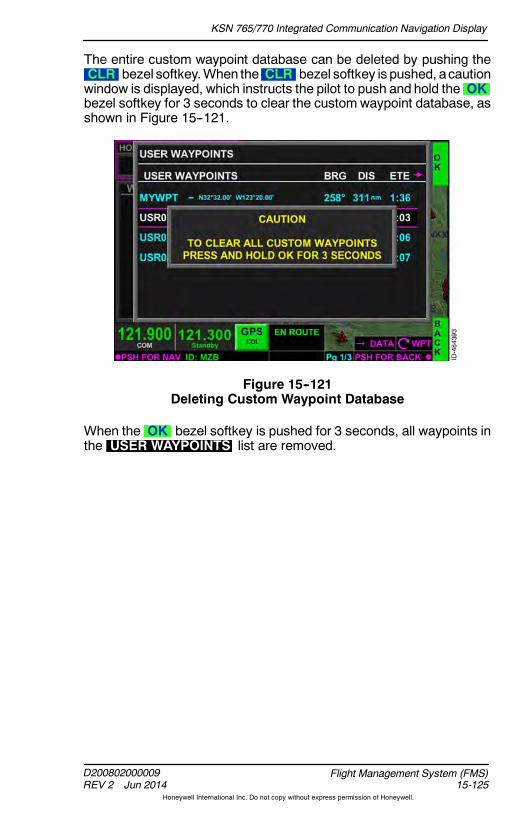
KSN 765/770 Integrated Communication Navigation Display
D200802000009REV 2 Jun 2014 15-125
Flight Management System (FMS)
Honeywell International Inc. Do not copy without express permission of Honeywell.
The entire custom waypoint database can be deleted by pushing theCLR bezel softkey.When the CLR bezel softkey is pushed, acautionwindow is displayed, which instructs the pilot to push and hold the OKbezel softkey for 3 seconds to clear the custom waypoint database, asshown in Figure 15--121.
Figure 15--121Deleting Custom Waypoint Database
When the OK bezel softkey is pushed for 3 seconds, all waypoints inthe USER WAYPOINTS list are removed.
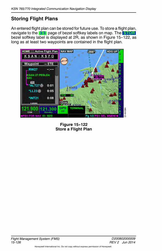
KSN 765/770 Integrated Communication Navigation Display
D200802000009REV 2 Jun 2014
Flight Management System (FMS)15-126
Honeywell International Inc. Do not copy without express permission of Honeywell.
Storing Flight Plans
An entered flight plan can be stored for future use. To store a flight plan,navigate to the 3/3 page of bezel softkey labels on map. The STORbezel softkey label is displayed at 2R, as shown in Figure 15--122, aslong as at least two waypoints are contained in the flight plan.
Figure 15--122Store a Flight Plan
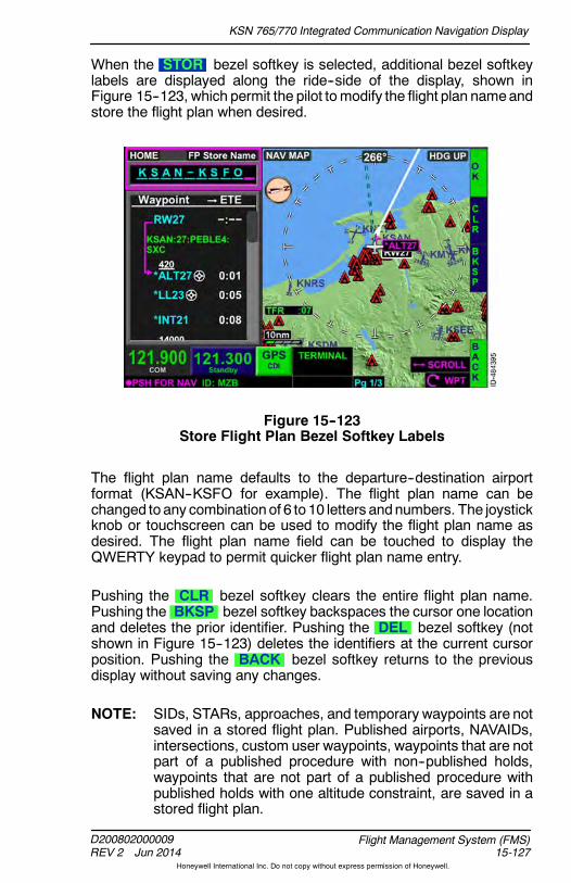
KSN 765/770 Integrated Communication Navigation Display
D200802000009REV 2 Jun 2014 15-127
Flight Management System (FMS)
Honeywell International Inc. Do not copy without express permission of Honeywell.
When the STOR bezel softkey is selected, additional bezel softkeylabels are displayed along the ride--side of the display, shown inFigure 15--123, which permit the pilot tomodify the flight plan nameandstore the flight plan when desired.
Figure 15--123Store Flight Plan Bezel Softkey Labels
The flight plan name defaults to the departure--destination airportformat (KSAN--KSFO for example). The flight plan name can bechanged to any combination of 6 to 10 letters andnumbers. The joystickknob or touchscreen can be used to modify the flight plan name asdesired. The flight plan name field can be touched to display theQWERTY keypad to permit quicker flight plan name entry.
Pushing the CLR bezel softkey clears the entire flight plan name.Pushing the BKSP bezel softkey backspaces the cursor one locationand deletes the prior identifier. Pushing the DEL bezel softkey (notshown in Figure 15--123) deletes the identifiers at the current cursorposition. Pushing the BACK bezel softkey returns to the previousdisplay without saving any changes.
NOTE: SIDs, STARs, approaches, and temporary waypoints are notsaved in a stored flight plan. Published airports, NAVAIDs,intersections, custom user waypoints, waypoints that are notpart of a published procedure with non--published holds,waypoints that are not part of a published procedure withpublished holds with one altitude constraint, are saved in astored flight plan.

KSN 765/770 Integrated Communication Navigation Display
D200802000009REV 2 Jun 2014
Flight Management System (FMS)15-128
Honeywell International Inc. Do not copy without express permission of Honeywell.
Pushing the OK bezel softkey stores the flight plan with the displayedname. When the same flight plan name already exists, an overwritewindow is displayed, as shown in Figure 15--124, which the pilot canselect OK to overwrite the previously stored flight plan or pushBACK and choose another name to store the flight plan.
Figure 15--124Overwrite Flight Plan
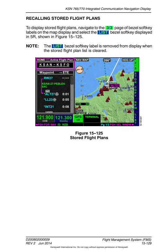
KSN 765/770 Integrated Communication Navigation Display
D200802000009REV 2 Jun 2014 15-129
Flight Management System (FMS)
Honeywell International Inc. Do not copy without express permission of Honeywell.
RECALLING STORED FLIGHT PLANS
To display stored flight plans, navigate to the 3/3 pageof bezel softkeylabels on themap display and select the LIST bezel softkey displayedin 5R, shown in Figure 15--125.
NOTE: The LIST bezel softkey label is removed from display whenthe stored flight plan list is cleared.
Figure 15--125Stored Flight Plans

KSN 765/770 Integrated Communication Navigation Display
D200802000009REV 2 Jun 2014
Flight Management System (FMS)15-130
Honeywell International Inc. Do not copy without express permission of Honeywell.
When the LIST bezel softkey is selected, SEL , INV , CLR ,DEL , and BACK bezel softkey labels are displayed andStored FP List is displayed in the FMS home window, as shown inFigure 15--126.
Figure 15--126Select a Stored Flight Plan
To activate a stored flight plan, use the joystick knob or touchscreen tohighlight the desired flight plan name in the stored flight plan list andpush the SEL bezel softkey.When the SEL bezel softkey is pushed,the right--side bezel softkey labels change, as shown in Figure 15--127.
Figure 15--127Activate a Stored Flight Plan

KSN 765/770 Integrated Communication Navigation Display
D200802000009REV 2 Jun 2014 15-131
Flight Management System (FMS)
Honeywell International Inc. Do not copy without express permission of Honeywell.
The following paragraphs describe the bezel softkey labels displayedon this page:
D The ACTV bezel softkey activates the stored flight plan displayedin the waypoint list window.
D The CHNG bezel softkey is displayed when any waypoint otherthan the origin is selected and permits the pilot to change any of theen route or destination waypoints before activating the flight plan.
D The DEL bezel softkey is displayed when any waypoint other thanthe origin is selected and permits the pilot to delete any of thedisplayed waypoints before activating the flight plan.
D The INS bezel softkey (not shown in Figure 15--127) is displayedwhen the cursor is not on a displayed waypoint.
D The CLR bezel softkey permits the pilot to clear the entire storedflight plan waypoint list.
D The PROC bezel softkey permits the pilot to add a desiredprocedure before activating the flight plan.
D The STOR bezel softkey moves the cursor to the flight plan namefield, which permits the pilot tomodify the flight plan name and storethe flight plan when desired.
When the ACTV bezel softkey is selected, the FMS mode changesfrom New Flight Plan Edit to Active Flight Plan , as shown inFigure 15--128. The stored flight plan is now active in the flight plan list.
Figure 15--128Stored Flight Plan Activated

KSN 765/770 Integrated Communication Navigation Display
D200802000009REV 2 Jun 2014
Flight Management System (FMS)15-132
Honeywell International Inc. Do not copy without express permission of Honeywell.
INVERT A STORED FLIGHT PLAN
Using the invert feature, the pilot can select a previously stored routeand navigate the flight plan waypoints in the opposite direction in whichthey are stored. A stored flight plan can be inverted by navigating to the3/3 of bezel softkey labels on themapdisplay and selecting the LISTbezel softkey in 5R, shown in Figure 15--129.
NOTE: Inverting a stored flight plan that contains a large number ofwaypoints may take a few minutes for the KSN to resolve.
Figure 15--129LIST Bezel Softkey Label

KSN 765/770 Integrated Communication Navigation Display
D200802000009REV 2 Jun 2014 15-133
Flight Management System (FMS)
Honeywell International Inc. Do not copy without express permission of Honeywell.
The desired flight plan is highlighted using the joystick knob ortouchscreen. For the example flight plan, a return trip from KSFO toKSAN is desired and the previously stored flight plan fromKSAN--KSFO is highlighted, as shown in Figure 15--130.
Figure 15--130Invert Flight Plan
After the desired flight plan is highlighted, the INV bezel softkey isselected. When selected, the INV bezel softkey label changes toINV , as shown in Figure 15--131.
Figure 15--131INV Bezel Softkey Label
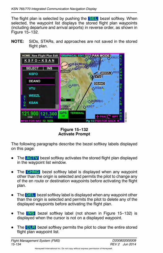
KSN 765/770 Integrated Communication Navigation Display
D200802000009REV 2 Jun 2014
Flight Management System (FMS)15-134
Honeywell International Inc. Do not copy without express permission of Honeywell.
The flight plan is selected by pushing the SEL bezel softkey. Whenselected, the waypoint list displays the stored flight plan waypoints(including departure and arrival airports) in reverse order, as shown inFigure 15--132.
NOTE: SIDs, STARs, and approaches are not saved in the storedflight plan.
Figure 15--132Activate Prompt
The following paragraphs describe the bezel softkey labels displayedon this page:
D The ACTV bezel softkey activates the stored flight plan displayedin the waypoint list window.
D The CHNG bezel softkey label is displayed when any waypointother than the origin is selected and permits the pilot to change anyof the en route or destination waypoints before activating the flightplan.
D The DEL bezel softkey label is displayed when any waypoint otherthan the origin is selected and permits the pilot to delete any of thedisplayed waypoints before activating the flight plan.
D The INS bezel softkey label (not shown in Figure 15--132) isdisplayed when the cursor is not on a displayed waypoint.
D The CLR bezel softkey permits the pilot to clear the entire storedflight plan waypoint list.

KSN 765/770 Integrated Communication Navigation Display
D200802000009REV 2 Jun 2014 15-135
Flight Management System (FMS)
Honeywell International Inc. Do not copy without express permission of Honeywell.
D The PROC bezel softkey permits the pilot to add a desiredprocedure before activating the flight plan.
D The STOR bezel softkey moves the cursor to the flight plan namefield, which permits the pilot tomodify the flight plan name and storethe flight plan when desired.
When the ACTV bezel softkey is selected, the FMS mode changesfrom New Flight Plan Edit to Flight Plan Active , as shown inFigure 15--133.
NOTE: The flight plan name field updates to display the newdeparture and arrival airports.
Figure 15--133Invert Flight Plan Active

KSN 765/770 Integrated Communication Navigation Display
D200802000009REV 2 Jun 2014
Flight Management System (FMS)15-136
Honeywell International Inc. Do not copy without express permission of Honeywell.
CLEARING STORED FLIGHT PLAN DATABASE
The entire stored flight plan database can be cleared by pushing theCLR bezel softkey, shown in Figure 15--134.
Figure 15--134CLR Bezel Softkey Label
When the CLR bezel softkey is pushed, a caution window isdisplayed, which instructs the pilot to push and hold the OK bezelsoftkey for 3 seconds to clear the stored flight plan database, as shownin Figure 15--135.
Figure 15--135Deleting Stored Flight Plan Database

KSN 765/770 Integrated Communication Navigation Display
D200802000009REV 2 Jun 2014 15-137
Flight Management System (FMS)
Honeywell International Inc. Do not copy without express permission of Honeywell.
When the OK bezel softkey in 1R is pushed for 3 seconds, all storedflight plans are cleared.
DELETING STORED FLIGHT PLANS
To delete a stored flight plan, navigate to the 3/3 page of bezel softkeylabels on the map display and select the LIST bezel softkey. Use thejoystick knob or touchscreen to select the desired flight plan. For theexample flight plan, CACOAST is selected to be deleted and ishighlighted, as shown in Figure 15--136.
Figure 15--136Delete a Stored Flight Plan

KSN 765/770 Integrated Communication Navigation Display
D200802000009REV 2 Jun 2014
Flight Management System (FMS)15-138
Honeywell International Inc. Do not copy without express permission of Honeywell.
Selecting the DEL bezel softkey displays CONFIRM DEL over theselected flight plan and OK and BACK bezel softkey labels on theright side of the display, as shown in Figure 15--137. Selecting the OKbezel softkey deletes the flight plan from the stored flight plan list.Selecting the BACK bezel softkey returns to the previous displaywithout making any changes.
Figure 15--137Confirm Deletion
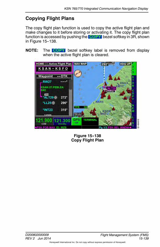
KSN 765/770 Integrated Communication Navigation Display
D200802000009REV 2 Jun 2014 15-139
Flight Management System (FMS)
Honeywell International Inc. Do not copy without express permission of Honeywell.
Copying Flight Plans
The copy flight plan function is used to copy the active flight plan andmake changes to it before storing or activating it. The copy flight planfunction is accessedby pushing the COPY bezel softkey in 3R, shownin Figure 15--138.
NOTE: The COPY bezel softkey label is removed from displaywhen the active flight plan is cleared.
Figure 15--138Copy Flight Plan

KSN 765/770 Integrated Communication Navigation Display
D200802000009REV 2 Jun 2014
Flight Management System (FMS)15-140
Honeywell International Inc. Do not copy without express permission of Honeywell.
When the COPY bezel softkey is pushed, the active flight plan iscopied to a new flight plan and the FMS mode changes toNew Flight Plan Edit , as shown in Figure 15--139.
Figure 15--139New Flight Plan Edit
The following paragraphs describe the bezel softkey labels displayedon this page:
D The PBD bezel softkey displays the TEMP WAYPOINT window,which permits the pilot to define a custom waypoint used to createa new waypoint in the flight plan.
D The STOR bezel softkey moves the cursor to the flight plan namefield, which permits the pilot tomodify the flight plan name and storethe flight plan when desired.
D The ACTV bezel softkey activates the stored flight plan displayedin the waypoint list window.
D The INS bezel softkey label is displayed when the cursor is not ona displayed waypoint.
D The DEL bezel softkey label (not shown in Figure 15--139) isdisplayed when any waypoint other than the origin is selected andpermits the pilot to delete any of the displayed waypoints beforeactivating the flight plan.
D The PROC bezel softkey permits the pilot to add a desiredprocedure before activating the flight plan.

KSN 765/770 Integrated Communication Navigation Display
D200802000009REV 2 Jun 2014 15-141
Flight Management System (FMS)
Honeywell International Inc. Do not copy without express permission of Honeywell.
FMS FLIGHT PLAN MAP DATA
Lines and curves are displayed on the map to connect successivewaypoints, transition onto a waypoint, display holding patterns andholding pattern entries, and display procedure turns on the map.
Flight Plan Segments -- The flight plan segments are solid white lines( ). The currently active segment (segment to the TO waypoint)is a magenta line ( ) when LNAV is captured and a green line( ) when LNAV is not captured.
Holding Patterns -- Holding patternsare represented by a symmetrical ovalracetrack symbol. Holding patternentries are displayed when the FMSrecommends a teardrop or parallel holdentry.
The hold entry and pattern is displayedin white when the hold is not active.When thehold entry is active, theholdingpattern is displayed in white and the hold
entry is displayed in magenta when guidance to the waypoint is active,green when guidance to the waypoint is available but not active, andwhite if theGPSposition fails. After theaircraft completes the hold entryby flying over the holding fix, the holding pattern entry is removed andonly the holding pattern is displayed. The holding pattern is displayedin magenta when guidance to the waypoint is active, green whenguidance to the waypoint is available but not active, and white if theGPS position fails.
NOTE: Holding pattern entries are approximate.
Procedure Turns -- Procedure turns arerepresented by a canted teardropsymbol on the navigation map display.Procedure turns are displayed in whitewhen the procedure turn is not the activeleg. When the procedure turn is theactive leg, the procedure turn isdisplayed in magenta when guidance tothe waypoint is active, green whenguidance to the waypoint is available butnot active, and white if the GPS position
fails. After the aircraft completes the procedure turn by intercepting theinbound leg, the procedure turn is removed from display and theinbound leg is displayed in magenta when guidance to the waypoint isactive, green when guidance to the waypoint is available but not active,and white if the GPS position fails.
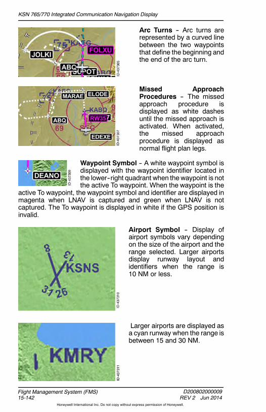
KSN 765/770 Integrated Communication Navigation Display
D200802000009REV 2 Jun 2014
Flight Management System (FMS)15-142
Honeywell International Inc. Do not copy without express permission of Honeywell.
Arc Turns -- Arc turns arerepresented by a curved linebetween the two waypointsthat define the beginning andthe end of the arc turn.
Missed ApproachProcedures -- The missedapproach procedure isdisplayed as white dashesuntil the missed approach isactivated. When activated,the missed approachprocedure is displayed asnormal flight plan legs.
Waypoint Symbol -- A white waypoint symbol isdisplayed with the waypoint identifier located inthe lower--right quadrant when thewaypoint is notthe active To waypoint. When the waypoint is the
active To waypoint, the waypoint symbol and identifier are displayed inmagenta when LNAV is captured and green when LNAV is notcaptured. The To waypoint is displayed in white if the GPS position isinvalid.
Airport Symbol -- Display ofairport symbols vary dependingon the size of the airport and therange selected. Larger airportsdisplay runway layout andidentifiers when the range is10 NM or less.
Larger airports are displayed asa cyan runway when the range isbetween 15 and 30 NM.
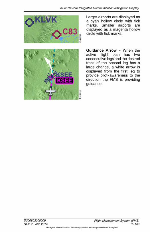
KSN 765/770 Integrated Communication Navigation Display
D200802000009REV 2 Jun 2014 15-143
Flight Management System (FMS)
Honeywell International Inc. Do not copy without express permission of Honeywell.
Larger airports are displayed asa cyan hollow circle with tickmarks. Smaller airports aredisplayed as a magenta hollowcircle with tick marks.
Guidance Arrow -- When theactive flight plan has twoconsecutive legs and the desiredtrack of the second leg has alarge change, a white arrow isdisplayed from the first leg toprovide pilot--awareness to thedirection the FMS is providingguidance.
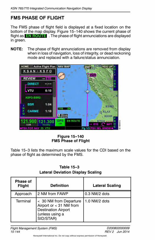
KSN 765/770 Integrated Communication Navigation Display
D200802000009REV 2 Jun 2014
Flight Management System (FMS)15-144
Honeywell International Inc. Do not copy without express permission of Honeywell.
FMS PHASE OF FLIGHT
The FMS phase of flight field is displayed at a fixed location on thebottom of the map display. Figure 15--140 shows the current phase offlight as EN ROUTE . The phase of flight annunciations are displayedin green.
NOTE: The phase of flight annunciations are removed from displaywhen in loss of navigation, loss of integrity, or dead reckoningmode and replaced with a failure/status annunciation.
Figure 15--140FMS Phase of Flight
Table 15--3 lists the maximum scale values for the CDI based on thephase of flight as determined by the FMS.
Table 15--3Lateral Deviation Display Scaling
Phase ofFlight Definition Lateral Scaling
Approach 2 NM from FAWP 0.3 NM/2 dots
Terminal 30 NM from DepartureAirport or 31 NM fromDestination Airport(unless using aSID/STAR)
1.0 NM/2 dots
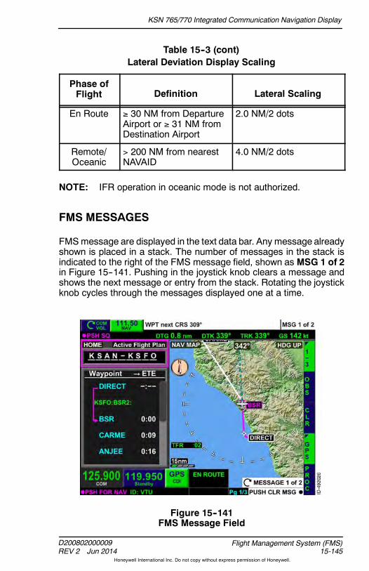
KSN 765/770 Integrated Communication Navigation Display
D200802000009REV 2 Jun 2014 15-145
Flight Management System (FMS)
Honeywell International Inc. Do not copy without express permission of Honeywell.
Table 15--3 (cont)Lateral Deviation Display Scaling
Phase ofFlight Lateral ScalingDefinition
En Route 30 NM from DepartureAirport or 31 NM fromDestination Airport
2.0 NM/2 dots
Remote/Oceanic
200 NM from nearestNAVAID
4.0 NM/2 dots
NOTE: IFR operation in oceanic mode is not authorized.
FMS MESSAGES
FMSmessage are displayed in the text data bar. Any message alreadyshown is placed in a stack. The number of messages in the stack isindicated to the right of the FMS message field, shown as MSG 1 of 2in Figure 15--141. Pushing in the joystick knob clears a message andshows the next message or entry from the stack. Rotating the joystickknob cycles through the messages displayed one at a time.
Figure 15--141FMS Message Field
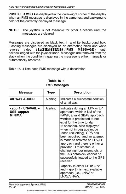
KSN 765/770 Integrated Communication Navigation Display
D200802000009REV 2 Jun 2014
Flight Management System (FMS)15-146
Honeywell International Inc. Do not copy without express permission of Honeywell.
PUSH CLRMSG D is displayed in the lower--right corner of the displaywhen an FMS message is displayed in the same text and backgroundcolor of the currently displayed message.
NOTE: The joystick is not available for other functions until themessages are cleared.
Messages are displayed as black text in a white background box.Flashing messages are displayed as an alternating black and whitereverse video ( FMS MESSAGE / FMS MESSAGE ) untilacknowledged with the joystick knob. Messages are removed from thestack when the condition triggering the message is either manually orautomatically resolved.
Table 15--4 lists each FMS message with a description.
Table 15--4FMS Messages
Message Type Description
AIRWAY ADDED Alerting Indicates a successful additionof an airway.
<appr1> UNAVAIL --USE <appr2>MINIMA
Alerting Indicates during an LPV or LPapproach, within 5 NM of theFAWP, a valid SBAS approachwindow is predicated to notexist for the time to alarm(6 seconds). Also displayedwhen not in degrade mode(dead reckoning), GPS hasbeen acquired, and an attemptis made to activate an LPV/LPapproach and there is either aprovider ID mismatch, achannel number mismatch, orthe FAS datablock cannot besuccessfully loaded to the GPSreceiver.<appr1> is either LP or LPVand <appr2> is next availableapproach (i.e., LNAV orLNAV/VNAV).

KSN 765/770 Integrated Communication Navigation Display
D200802000009REV 2 Jun 2014 15-147
Flight Management System (FMS)
Honeywell International Inc. Do not copy without express permission of Honeywell.
Table 15--4 (cont)FMS Messages
Message DescriptionType
BRG/CRS MUST BEIN TRUE
Alerting Indicates the bearing entrymust be followed by a T (forTrue) because the referencedwaypoint is outside thecoverage of the magneticvariation table.
DB INVALID -- USERWPT/FPL DBERASED
Alerting Displayed when the integritycheck for the custom waypointfile or the custom flight plan filefails.
DUPLICATE DB WPT-- RENAME
Alerting Indicates the entered USERwaypoint identifier is aduplicate identifier within theNAV database.
ENTERING POLARREGION
Alerting Displayed when the aircraftgoes above North 89 or belowSouth 89.
EXITING HOLD Alerting Displayed when all of thefollowing conditions are met:D The altitude hold (HA) leg is
the next leg (the leg after theTO)
D The aircraft exceeds thetermination altitudeof theHAleg
D TheETE to thehold fix is lessthan 1 minute.
The message is removed whenthe HA leg is sequenced.
EXITING POLARREGION
Alerting Displayed when the aircraftgoes below North 88 or aboveSouth 88.
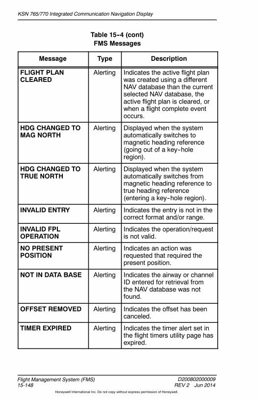
KSN 765/770 Integrated Communication Navigation Display
D200802000009REV 2 Jun 2014
Flight Management System (FMS)15-148
Honeywell International Inc. Do not copy without express permission of Honeywell.
Table 15--4 (cont)FMS Messages
Message DescriptionType
FLIGHT PLANCLEARED
Alerting Indicates the active flight planwas created using a differentNAV database than the currentselected NAV database, theactive flight plan is cleared, orwhen a flight complete eventoccurs.
HDG CHANGED TOMAG NORTH
Alerting Displayed when the systemautomatically switches tomagnetic heading reference(going out of a key--holeregion).
HDG CHANGED TOTRUE NORTH
Alerting Displayed when the systemautomatically switches frommagnetic heading reference totrue heading reference(entering a key--hole region).
INVALID ENTRY Alerting Indicates the entry is not in thecorrect format and/or range.
INVALID FPLOPERATION
Alerting Indicates the operation/requestis not valid.
NO PRESENTPOSITION
Alerting Indicates an action wasrequested that required thepresent position.
NOT IN DATA BASE Alerting Indicates the airway or channelID entered for retrieval fromthe NAV database was notfound.
OFFSET REMOVED Alerting Indicates the offset has beencanceled.
TIMER EXPIRED Alerting Indicates the timer alert set inthe flight timers utility page hasexpired.

KSN 765/770 Integrated Communication Navigation Display
D200802000009REV 2 Jun 2014 15-149
Flight Management System (FMS)
Honeywell International Inc. Do not copy without express permission of Honeywell.
Table 15--4 (cont)FMS Messages
Message DescriptionType
UNABLE ADDWPT(S) -- FPL FULL
Alerting Displayed when the pilotattempts to enter more than101 waypoints in a single flightplan.
UNABLE <appr> Alerting Indicates the FAS datablock forthe approach fails CRC orunable to load.<appr1> is the approachselected (i.e., LP or LPV).
UNABLEAPPROACHMODIFICATION
Alerting Indicates an attempt is madeto create an OBS to the FAWPor MAWP waypoints.
UNABLE DEL --USED BY ACTIVEFPL
Alerting Indicates the pilot attempted todelete from storage a waypointthat is used in the active flightplan.
UNABLE HOLDCHANGE
Alerting Indicates an attempt to changethe course, turn direction, orthe holding quadrant of thehold while actively flying thehold. Also displayed when thehold leg is defined by time andan attempt to change todistance is made, or viceversa.
UNABLE FPL LOAD-- INVALID WPT(s)
Alerting Indicates a stored flight planinsertion request is receivedand a waypoint in the storedflight plan does not exist in theNAV database or customdatabase.
UNABLE OFFSET Alerting Indicates an attempt to insertan offset during holding, apattern, or a terminal areaprocedure.

KSN 765/770 Integrated Communication Navigation Display
D200802000009REV 2 Jun 2014
Flight Management System (FMS)15-150
Honeywell International Inc. Do not copy without express permission of Honeywell.
Table 15--4 (cont)FMS Messages
Message DescriptionType
UNABLE STORE --FPL STORAGEFULL
Alerting Indicates attempt to storeactive flight plan will exceedmaximum of 99 stored flightplans in the custom databaseor more than 500 user definedwaypoints.
UNABLE STORE --WPT STORAGEFULL
Alerting Indicates the storage area forpilot--defined waypoints is full.
WPT Alerting Indicates a discontinuity or lastwaypoint in the flight plan.
WPT CRS XXX Alerting Indicates the start of a turn.XXX indicates the next courseor turn in degrees magnetic ortrue.
WPT HOLD next Alerting/Flashing
Indicates an impending hold.Note there is no message atthe start of the hold.
WPT next CRS XXX Alerting/Flashing
Indicates an impending turn orwhen the final waypoint in theflight plan is the activewaypoint and the unit hasautomatically switched to aFROM operation at the activewaypoint. Also for direct to fix,arc to fix, and radius to fix legtypes. XXX indicates the nextcourse or turn in degreesmagnetic or true.
WPT PROC TURN Alerting Indicates the start of aprocedure turn.
WPT PROC TURNnext
Alerting/Flashing
Indicates an impendingprocedure turn.
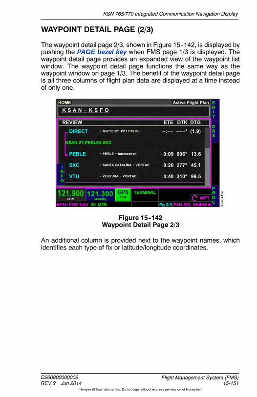
KSN 765/770 Integrated Communication Navigation Display
D200802000009REV 2 Jun 2014 15-151
Flight Management System (FMS)
Honeywell International Inc. Do not copy without express permission of Honeywell.
WAYPOINT DETAIL PAGE (2/3)
The waypoint detail page 2/3, shown in Figure 15--142, is displayed bypushing the PAGE bezel key when FMS page 1/3 is displayed. Thewaypoint detail page provides an expanded view of the waypoint listwindow. The waypoint detail page functions the same way as thewaypoint window on page 1/3. The benefit of the waypoint detail pageis all three columns of flight plan data are displayed at a time insteadof only one.
Figure 15--142Waypoint Detail Page 2/3
An additional column is provided next to the waypoint names, whichidentifies each type of fix or latitude/longitude coordinates.

KSN 765/770 Integrated Communication Navigation Display
D200802000009REV 2 Jun 2014
Flight Management System (FMS)15-152
Honeywell International Inc. Do not copy without express permission of Honeywell.
Focus can be given to either the waypoint list window, shown inFigure 15--142, or the home window, shown in Figure 15--143, bypushing in the joystick knob or using the touchscreen. Both windowsdisplay the same bezel softkey labels previously described when FMSpage 1/3 is displayed.
Figure 15--143Waypoint Detail Page -- Home

KSN 765/770 Integrated Communication Navigation Display
D200802000009REV 2 Jun 2014 15-153
Flight Management System (FMS)
Honeywell International Inc. Do not copy without express permission of Honeywell.
UTILITY PAGE
The UTILITY page, shown in Figure 15--144, is displayed by pushingthe PAGE bezel key when FMS page 2/3 is displayed. The UTILITYpage has seven touchscreen softkeys which permit access to variouspages that provide FMS functions such as calculations and predictionsfor informational purposes during the flight.
Figure 15--144UTILITY Page
Embossed touchscreen softkeys displayed in cyan are selectable toeither access another sub--page or to input data required forcalculations. Gray boxes are not selectable and are used for displaypurposes only.
The GPS 95%confidence horizontal and vertical accuracy is displayedin feet next to the HPE and VPE labels. When the GPS 95%confidence horizontal or vertical accuracy is greater than 7,500meters,the displayed values are replaced with dashes ( -------- ).
TheGPS date and time in UTCat the top--middle of the page. The flighttime is displayed and is the same flight time displayed on the flighttimers page. When the GPS position is valid or FMS dead reckoningmode is active, the aircraft present position is displayed inlatitude/longitude format in the center of the screen. When the GPSposition is invalid and FMS dead reckoning mode is active, thelatitude/longitude values are removed from display and replaced withdashes ( --------.---- ).
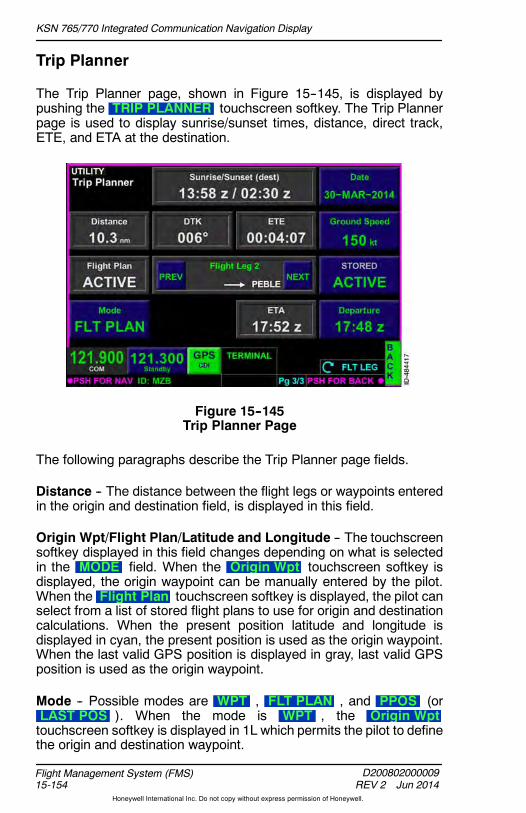
KSN 765/770 Integrated Communication Navigation Display
D200802000009REV 2 Jun 2014
Flight Management System (FMS)15-154
Honeywell International Inc. Do not copy without express permission of Honeywell.
Trip Planner
The Trip Planner page, shown in Figure 15--145, is displayed bypushing the TRIP PLANNER touchscreen softkey. The Trip Plannerpage is used to display sunrise/sunset times, distance, direct track,ETE, and ETA at the destination.
Figure 15--145Trip Planner Page
The following paragraphs describe the Trip Planner page fields.
Distance -- The distance between the flight legs or waypoints enteredin the origin and destination field, is displayed in this field.
Origin Wpt/Flight Plan/Latitude and Longitude -- The touchscreensoftkey displayed in this field changes depending on what is selectedin the MODE field. When the Origin Wpt touchscreen softkey isdisplayed, the origin waypoint can be manually entered by the pilot.When the Flight Plan touchscreen softkey is displayed, the pilot canselect from a list of stored flight plans to use for origin and destinationcalculations. When the present position latitude and longitude isdisplayed in cyan, the present position is used as the origin waypoint.When the last valid GPS position is displayed in gray, last valid GPSposition is used as the origin waypoint.
Mode -- Possible modes are WPT , FLT PLAN , and PPOS (orLAST POS ). When the mode is WPT , the Origin Wpttouchscreen softkey is displayed in 1L which permits the pilot to definethe origin and destination waypoint.

KSN 765/770 Integrated Communication Navigation Display
D200802000009REV 2 Jun 2014 15-155
Flight Management System (FMS)
Honeywell International Inc. Do not copy without express permission of Honeywell.
When themode is FLT PLAN , the Flight Plan touchscreen softkeyis displayed in 1L which permits the pilot to choose from stored flightplans to use for origin and destination calculations. In addition,Flight Leg is displayed in the center of the page and to the right of theFlight Plan touchscreen softkey, as shown in Figure 15--145. Theflight leg function permits the pilot view trip planner on a leg--by--legbasis. The flight legs are changed by using the interactive touchscreento push the PREV or NEXT touchscreen softkey or by rotating thejoystick knob as indicated by FLT LEG displayed in the lower--rightcorner.
Present position is selectable when the current GPS position is valid.When the mode is PPOS , the present position latitude and longitudeare displayed in cyan in 1L, which uses the present aircraft position asthe origin waypoint. When the current GPS position is not valid, lastknow GPS position is selectable. When the mode is LAST POS , thelast valid GPS position is displayed in 1L and used for calculations.
Sunrise/Sunset -- The sunrise and sunset times at the destination aredisplayed in this field.
DTK -- The desired track from the origin waypoint to the destination isdisplayed in this field when the mode key in 2L is WPT . The desiredtrack from the present position (or last GPS position) to the destinationis displayed in this field when the mode key in 2L is PPOS (orLAST POS ). The desired track from the selected flight plan leg isdisplayed in this field when the mode key in 2L is FLT PLAN and avalid flight plan exists.
ETE -- The estimated time en route to the destination in HH:MM:SS(hours:minutes:seconds) format is displayed in this field.
ETA -- The estimated time of arrival at the destination is displayed inZulu in this field.
Date -- The date is entered by selecting the Date touchscreen softkey.
Ground Speed -- The planned groundspeed is entered in knots byselecting the Ground Speed touchscreen softkey.
Destination -- The Destination touchscreen softkey is displayedwhen the mode in 4L is either WPT or PPOS. The pilot can manuallydefine the destination waypoint in this mode. The STORED/ACTIVEtouchscreen softkey is displayed when the mode in 2L is FLT PLAN.The pushing the STORED/ACTIVE touchscreen softkey toggles thedestination from the stored flight plan or the active flight plandestination.

KSN 765/770 Integrated Communication Navigation Display
D200802000009REV 2 Jun 2014
Flight Management System (FMS)15-156
Honeywell International Inc. Do not copy without express permission of Honeywell.
Departure -- The departure time is entered in Zulu by selecting theDeparture touchscreen softkey.
Back -- Pushing the BACK bezel softkey displays the UTILITY page.
RAIM Prediction
The RAIM prediction page, shown in Figure 15--146, is displayed bypushing the RAIM Predict touchscreen softkey. The RAIM predictionpage is used to predict RAIM availability at the entered waypoint andtime.
Figure 15--146RAIM Predict
The following paragraphs describe the RAIM prediction page fields.
Destination -- The Destination field defaults to green dashes( ------------ ). The pilot can enter any International Civil AviationOrganization (ICAO) airport or FMS waypoint to compute a predictiveRAIMsolution.When the Destination touchscreen softkey is pushed,a QWERTY keypad is displayed that permits the pilot to enter thedesired waypoint to compute RAIM availability.
ETA -- The ETA field defaults to 00:00 z . The pilot can enter any time(within 24 hours of the current time) to compute a predictive RAIMsolution. The time is entered in Zulu time, as indicated by the z afterthe time.
When the ETA touchscreen softkey is pushed, a window is displayedthat permits the pilot to enter the ETA time in Zulu using the interactivetouchscreen. The entry range is 0 to 2359 and in 1--minute increments.

KSN 765/770 Integrated Communication Navigation Display
D200802000009REV 2 Jun 2014 15-157
Flight Management System (FMS)
Honeywell International Inc. Do not copy without express permission of Honeywell.
Press To -- The Press To field defaults to green dashes ( -------- ).When a waypoint is entered, the field changes to COMPUTE . Whenthe COMPUTE touchscreen softkey is pushed, the field changes toCANCEL , which permits the pilot to cancel the current RAIMcomputations.
The ETA or waypoint data fields can be changed to initiate a newrequest for computation of RAIM information, provided both the ETAandwaypoint informationare entered. The enteredwaypoint is retainedwhen the window is closed such that the data is redisplayed on anysubsequent access to the page, however the ETA field is blanked andmust be re--entered each time.
RAIM STATUS -- The RAIM status field displays the status of RAIMpredictions at the entered waypoint and arrival time. The following arepossible status messages displayed in this field and the associatedmeaning.
D ENTER DESTINATION -- ETA -- A waypoint and valid ETA must beentered in the waypoint fields before any predictions can be made.
D READY -- RAIM status can be computed by pushing thePress To COMPUTE touchscreen softkey displayed in 4R.
D COMPUTING -- RAIM computation is in progress.
D COMPUTETIMEDOUT -- RAIM prediction response from the FMShas not been received within 45 seconds.
D COMPUTE FAILED -- RAIM prediction response from the FMSindicates that the computation failed.
D AVAILABLE -- RAIM prediction response from the FMS indicatesthat the computation succeeded and RAIM is available.
D NOT AVAILABLE -- RAIM prediction response from the FMSindicates that the computation succeeded and RAIM is notavailable.
Back -- Pushing the BACK bezel softkey displays the UTILITY page.
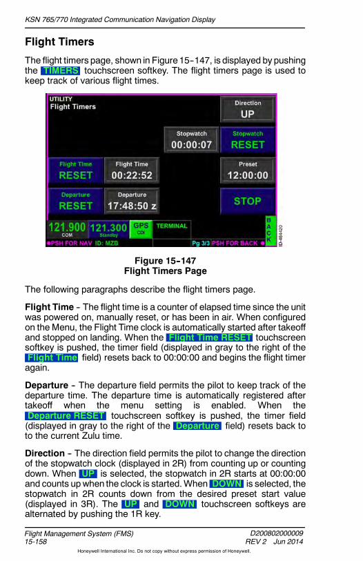
KSN 765/770 Integrated Communication Navigation Display
D200802000009REV 2 Jun 2014
Flight Management System (FMS)15-158
Honeywell International Inc. Do not copy without express permission of Honeywell.
Flight Timers
The flight timers page, shown in Figure 15--147, is displayed by pushingthe TIMERS touchscreen softkey. The flight timers page is used tokeep track of various flight times.
Figure 15--147Flight Timers Page
The following paragraphs describe the flight timers page.
Flight Time -- The flight time is a counter of elapsed time since the unitwas powered on, manually reset, or has been in air. When configuredon the Menu, the Flight Time clock is automatically started after takeoffand stopped on landing. When the Flight Time RESET touchscreensoftkey is pushed, the timer field (displayed in gray to the right of theFlight Time field) resets back to 00:00:00 and begins the flight timeragain.
Departure -- The departure field permits the pilot to keep track of thedeparture time. The departure time is automatically registered aftertakeoff when the menu setting is enabled. When theDeparture RESET touchscreen softkey is pushed, the timer field(displayed in gray to the right of the Departure field) resets back toto the current Zulu time.
Direction -- The direction field permits the pilot to change the directionof the stopwatch clock (displayed in 2R) from counting up or countingdown. When UP is selected, the stopwatch in 2R starts at 00:00:00and counts upwhen the clock is started.When DOWN is selected, thestopwatch in 2R counts down from the desired preset start value(displayed in 3R). The UP and DOWN touchscreen softkeys arealternated by pushing the 1R key.
KSN 765/770 Integrated Communication Navigation Display
D200802000009REV 2 Jun 2014 15-159
Flight Management System (FMS)
Honeywell International Inc. Do not copy without express permission of Honeywell.
Stopwatch RESET -- The stopwatch reset touchscreen softkeypermits the pilot to reset the stopwatch timer back to the original value.The stopwatch counter is displayed to the left of the RESETtouchscreen softkey.
Preset -- The Preset touchscreen softkey controls and displays thepreset value. How the preset value is used when the RESETtouchscreen softkey is selected depends on the stopwatch direction(displayed in 1R). The preset value is always displayed when thedirection is DOWN , but toggles between cleared and displayedwhenthe direction is up.
When thedirection key displays DOWN and the Preset touchscreensoftkey is pushed, the stopwatch alert is deactivated and a window isdisplayed that permits the pilot to enter the desired stopwatch startvalue.
When the direction key displays UP , pushing the Presettouchscreen softkey clears the preset value and deactivates thestopwatch alert. When the preset value is cleared and the directiontouchscreen softkey displays UP , pushing the Preset touchscreensoftkey displays a window which permits the pilot to enter the desiredstopwatch alert value.
When a preset time is reached on the stopwatch, the FMS messageTIMER EXPIRED is displayed.
START/STOP -- The START touchscreen softkey permits the pilot tostart the timer in 2R. The START touchscreen softkey changes toSTOP when selected. The STOP touchscreen softkey permits thepilot to stop the timer in 2R. The STOP touchscreen softkey changesto START when selected.
NOTE: When STOP is displayed, the direction in 1R and presetvalue in 3R are not selectable until the stopwatch is stopped.
Back -- Pushing the BACK bezel softkey displays the Utility page.

KSN 765/770 Integrated Communication Navigation Display
D200802000009REV 2 Jun 2014
Flight Management System (FMS)15-160
Honeywell International Inc. Do not copy without express permission of Honeywell.
Fuel Calculator
CAUTION
THE FMS FUEL CALCULATOR DATA IS ADVISORYINFORMATION ONLY. THE FMS FUEL CALCULATOR DATAMUST NOT BE USED IN LIEU OF THE PRIMARY FUELINDICATION DISPLAYS ON THE AIRCRAFT. ACTUAL FUELFLOW IS NOT CALCULATED. ACCURACY DEPENDS ON THEDATA PROVIDED BY THE PILOT.
The fuel calculator page, shown in Figure 15--148, is displayed bypushing the FUEL CALCULATOR touchscreen softkey. The fuelcalculator page provides advisory fuel calculations and should be usedfor planning purposes only.
Figure 15--148Fuel Calculator Page
All FMS calculation fields default to dashes ( ------------ ) until therequired parameters are entered by the pilot.
NOTE: Pilot--entered fuel parameters are not stored after a powercycle.
The following paragraphs describe the fuel calculator page.
Fuel to -- The amount of fuel to get from the origin waypoint in 1L to thedestination waypoint in 3R or the active waypoint is displayed with aresolution of 0.1 gallons. This is a display--only field and pilot--entry isnot permitted.
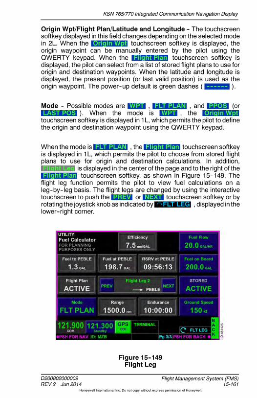
KSN 765/770 Integrated Communication Navigation Display
D200802000009REV 2 Jun 2014 15-161
Flight Management System (FMS)
Honeywell International Inc. Do not copy without express permission of Honeywell.
Origin Wpt/Flight Plan/Latitude and Longitude -- The touchscreensoftkey displayed in this field changes depending on the selectedmodein 2L. When the Origin Wpt touchscreen softkey is displayed, theorigin waypoint can be manually entered by the pilot using theQWERTY keypad. When the Flight Plan touchscreen softkey isdisplayed, the pilot can select from a list of stored flight plans to use fororigin and destination waypoints. When the latitude and longitude isdisplayed, the present position (or last valid position) is used as theorigin waypoint. The power--up default is green dashes ( ------------ ).
Mode -- Possible modes are WPT , FLT PLAN , and PPOS (orLAST POS ). When the mode is WPT , the Origin Wpttouchscreen softkey is displayed in 1L, which permits the pilot to definethe origin and destination waypoint using the QWERTY keypad.
When themode is FLT PLAN , the Flight Plan touchscreen softkeyis displayed in 1L, which permits the pilot to choose from stored flightplans to use for origin and destination calculations. In addition,Flight Leg is displayed in the center of the page and to the right of theFlight Plan touchscreen softkey, as shown in Figure 15--149. Theflight leg function permits the pilot to view fuel calculations on aleg--by--leg basis. The flight legs are changed by using the interactivetouchscreen to push the PREV or NEXT touchscreen softkey or byrotating the joystick knobas indicatedby FLT LEG , displayed in thelower--right corner.
Figure 15--149Flight Leg
KSN 765/770 Integrated Communication Navigation Display
D200802000009REV 2 Jun 2014
Flight Management System (FMS)15-162
Honeywell International Inc. Do not copy without express permission of Honeywell.
Present position is selectable when the current GPS position is valid.When the mode is PPOS , the present position latitude and longitudeare displayed in cyan in 1L, which uses the present aircraft position asthe origin waypoint. When the current GPS position is not valid, lastknow GPS position is selectable. When the mode is LAST POS , thelast valid GPS position is displayed in 1L and used for calculations.
The power--up default is WPT.
Efficiency -- The FMS calculated fuel efficiency is displayed in this fieldwith a resolution of 0.1 NM per gallon.
Fuel at -- TheFMScalculatedamount of fuel at the destinationwaypointis displayed in this field with a resolution of 0.1 gallon.
Range -- The FMS calculated range is displayed in this field with aresolution of 0.1 NM.
RSRV at -- The FMS calculated reserves of fuel remaining at thedestination is displayed in this field in HH:MM:SS format.
Endurance -- The FMS calculated endurance is displayed in this fieldin HH:MM:SS format.
Fuel Flow -- The fuel flow is entered in this field with a resolution of0.1 gallon per hour. The power--up default is 0.0 GAL/HR .
Fuel on Board -- The amount of fuel--on--board is entered in this field.The power--up default is 0.0 GAL . The amount of fuel on board isenteredwith a resolution of 0.1 gallon.When fuel is added to theaircraft,the pilot must manually update the fuel quantity.
Destination -- The Destination touchscreen softkey is displayedwhen the mode in 4L is either WPT or PPOS. The pilot can manuallydefine the destination waypoint in this mode. The STORED/ACTIVEtouchscreen softkey toggles the destination from the stored flight planor the active flight plan destination. When ACTIVE is selected, theFlight Plan touchscreen softkey in 1L becomes grayed out anddisplays ACTIVE . The power--up default is green dashes ( ---------- ).
Ground Speed -- The groundspeed is entered in this field in knots. Thepower--up default is 00 KT .
Back -- Pushing the BACK bezel softkey displays the UTILITY page.
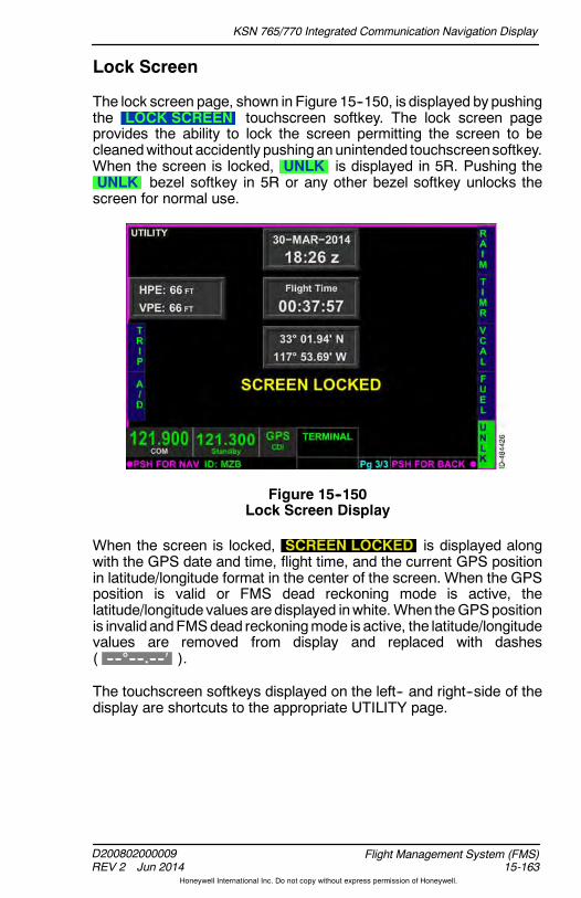
KSN 765/770 Integrated Communication Navigation Display
D200802000009REV 2 Jun 2014 15-163
Flight Management System (FMS)
Honeywell International Inc. Do not copy without express permission of Honeywell.
Lock Screen
The lock screen page, shown in Figure 15--150, is displayed by pushingthe LOCK SCREEN touchscreen softkey. The lock screen pageprovides the ability to lock the screen permitting the screen to becleanedwithout accidently pushinganunintended touchscreensoftkey.When the screen is locked, UNLK is displayed in 5R. Pushing theUNLK bezel softkey in 5R or any other bezel softkey unlocks thescreen for normal use.
Figure 15--150Lock Screen Display
When the screen is locked, SCREEN LOCKED is displayed alongwith the GPS date and time, flight time, and the current GPS positionin latitude/longitude format in the center of the screen. When the GPSposition is valid or FMS dead reckoning mode is active, thelatitude/longitude values are displayed inwhite. When theGPSpositionis invalid andFMSdead reckoningmode is active, the latitude/longitudevalues are removed from display and replaced with dashes( --------.---- ).
The touchscreen softkeys displayed on the left-- and right--side of thedisplay are shortcuts to the appropriate UTILITY page.

KSN 765/770 Integrated Communication Navigation Display
D200802000009REV 2 Jun 2014
Flight Management System (FMS)15-164
Honeywell International Inc. Do not copy without express permission of Honeywell.
Blank Page

KSN 765/770 Integrated Communication Navigation Display
D200802000009REV 2 Jun 2014 16-1
Database Loading Procedures
Honeywell International Inc. Do not copy without express permission of Honeywell.
16. Database Loading Procedures
INTRODUCTION
This section describes how to update the various databases installedon the KSN 765/770.
DATABASE LOADING OVERVIEW
Databaseupdates are downloaded from the internet and installed usinga USB drive and port on the front of the unit. Instructional videos anddatabases can be downloaded from the following website:
https://wingmanservices.bendixking.com/wingman/ksn.do
Database updates require a subscription. The database subscription ispaired with the unit during installation. The paired USB memory stickis provided by the installer to the operator for performing databaseupdates. Thedatabase subscription canbepurchased for theAmericasRegion or International Region.
Database updatesmust be downloaded to aUSB drive which is at least8 GB in size. A USB thumb drive uniquely formatted for use with theKSN 765/770 is supplied with the unit. Ensure the KSN 765/770 ispowered off before beginning any database updates.
TheUSB port is located on the front of the bezel on thebottom left side and accepts a standard sized USBmemory stick (thumb drive). TheUSB port has a coverwhich should be kept on until the USB port is requiredfor use.
CAUTION
USE OF THE USB PORT IN FLIGHT IS NOT AUTHORIZED ANDCAN CAUSE A RESET.

KSN 765/770 Integrated Communication Navigation Display
D200802000009REV 2 Jun 2014
Database Loading Procedures16-2
Honeywell International Inc. Do not copy without express permission of Honeywell.
With the unit powered off, insert the USB drive into the USB port in thefront of the unit. Whenpower is applied to the KSN765/770, a databaseloading page is displayed, as shown in Figure 16--1. On this page, theinstaller can choose which databases are to be installed and see howmuch time each database installation will take.
NOTE: The KSN 765/770 does not have a power button. The unitpowers--on with the aircraft avionics.
Figure 16--1Database Loading Page
The KSNDatabases column displays the currently installed databasesand version numbers. The installed databases are FMS Nav, MovingMap, Cultural, Obstacle, Terrain, and Charts. The database versionnumber, start date, and status ( Valid , Expired , or Early ) isdisplayed for each database.
Chart databases are provided directly by Seattle Avionics by accessingthe following website:
http://www.seattleavionics.com/ChartData/Default.aspx?TargetDevice=KSN
The USB Databases column lists each database as the same, newer,older, or not present on the USB drive. The database version numberand start date are displayed for each database. When the installeddatabase and the USB database are the same, Same is displayedabove the version number. When the USB database is newer than theinstalled database, Newer is displayed above the version number.When the USB database is older than the installed database, Olderis displayed above the version number. When an installed database isnot contained on the USB drive, Not Present is displayed.
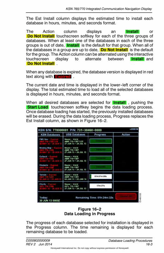
KSN 765/770 Integrated Communication Navigation Display
D200802000009REV 2 Jun 2014 16-3
Database Loading Procedures
Honeywell International Inc. Do not copy without express permission of Honeywell.
The Est Install column displays the estimated time to install eachdatabase in hours, minutes, and seconds format.
The Action column displays an Install orDo Not Install touchscreen softkey for each of the three groups ofdatabases. When at least one of the databases in each of the threegroups is out of date, Install is the default for that group. When all ofthe databases in a group are up to date, Do Not Install is the defaultfor the group. The Action column canbe alternatedusing the interactivetouchscreen display to alternate between Install andDo Not Install .
When any database is expired, the database version is displayed in redtext along with Expired .
The current date and time is displayed in the lower--left corner of thedisplay. The total estimated time to load all of the selected databasesis displayed in hours, minutes, and seconds format.
When all desired databases are selected for Install , pushing theStart Load touchscreen softkey begins the data loading process.Once database loading has started, the previously installed databaseswill be erased. During the data loading process, Progress replaces theEst Install column, as shown in Figure 16--2.
Figure 16--2Data Loading in Progress
The progress of each database selected for installation is displayed inthe Progress column. The time remaining is displayed for eachremaining database to be loaded.

KSN 765/770 Integrated Communication Navigation Display
D200802000009REV 2 Jun 2014
Database Loading Procedures16-4
Honeywell International Inc. Do not copy without express permission of Honeywell.
Dataloading can be canceled by pushing the Cancel All touchscreensoftkey.
NOTE: If the Cancel All touchscreen softkey is pushed, nodatabases will be loaded onto the KSNuntil database loadingis completed successfully.
Canceling the dataloading process can have severe adverse effects,such as corrupting the databases and software. Dataloading should notbe canceled during the dataloading process.
When dataloading for a database is complete, Complete is displayednext to the database. When the loading of all databases is complete,Return is displayed in the lower--right corner, as shown inFigure 16--3.
Figure 16--3Database Loading Complete
Pushing the Return touchscreen softkey returns to the originaldatabase loading page. When dataloading is complete, remove theUSB stick and cycle power on the KSN 765/770.

KSN 765/770 Integrated Communication Navigation Display
D200802000009REV 2 Jun 2014 16-5
Database Loading Procedures
Honeywell International Inc. Do not copy without express permission of Honeywell.
Dataloading Errors
Table 16--1 lists possible error messages encountered during thedataloading process and the associated corrective action.
Table 16--1Dataloading Errors
MessageSplashScreen
KSNDatabases
USBDatabases Criteria
CorrectiveAction
CheckInternal SDCard
X Missing orcorruptinternal SDcard
Replace theinternal SDcard
Not Present X X If thedatabase isnot presenton thedevice
KSNDatabases:Downloaddatabasesfrom the WebPortal and loadonto the KSN
USBDatabases:Downloaddatabasesfrom the WebPortal
Same X If thedatabasecurrently onthe USB isthe sameas thedatabase inthe KSN
No actionrequired
Newer X If thedatabasecurrently onthe USB isnewer thanthedatabase inthe KSN
Download thenewerdatabase ontothe KSN

KSN 765/770 Integrated Communication Navigation Display
D200802000009REV 2 Jun 2014
Database Loading Procedures16-6
Honeywell International Inc. Do not copy without express permission of Honeywell.
Table 16--1 (cont)Dataloading Errors
MessageCorrectiveActionCriteria
USBDatabases
KSNDatabases
SplashScreen
Older X If thedatabasecurrently onthe USB isolder thanthedatabase inthe KSN
If desired, loadthe olderdatabase ontothe KSN (notrecommended)
Expired X X If thedatabase isexpired
KSNDatabase:Download avalid databasefrom the WebPortal and loadonto the KSN.
USBDatabases:Only load anexpireddatabase ontothe KSN ifthere is nodatabase onthe KSN or ifthe USBdatabase isnewer.
Dif Region X The Regionis differentbetweenthe KSNdatabaseand theUSBdatabase
Load the newregioninformationonto the KSN ifdesired
NotAuthorized
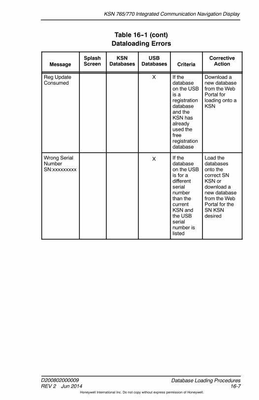
KSN 765/770 Integrated Communication Navigation Display
D200802000009REV 2 Jun 2014 16-7
Database Loading Procedures
Honeywell International Inc. Do not copy without express permission of Honeywell.
Table 16--1 (cont)Dataloading Errors
MessageCorrectiveActionCriteria
USBDatabases
KSNDatabases
SplashScreen
Reg UpdateConsumed
X If thedatabaseon the USBis aregistrationdatabaseand theKSN hasalreadyused thefreeregistrationdatabase
Download anew databasefrom the WebPortal forloading onto aKSN
Wrong SerialNumberSN:xxxxxxxxx
X If thedatabaseon the USBis for adifferentserialnumberthan thecurrentKSN andthe USBserialnumber islisted
Load thedatabasesonto thecorrect SNKSN ordownload anew databasefrom the WebPortal for theSN KSNdesired

KSN 765/770 Integrated Communication Navigation Display
D200802000009REV 2 Jun 2014
Database Loading Procedures16-8
Honeywell International Inc. Do not copy without express permission of Honeywell.
Blank Page
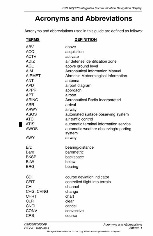
KSN 765/770 Integrated Communication Navigation Display
D200802000009REV 3 Nov 2014 Abbrev--1
Acronyms and Abbreviations
Honeywell International Inc. Do not copy without express permission of Honeywell.
Acronyms and Abbreviations
Acronyms and abbreviations used in this guide are defined as follows:
TERMS DEFINITION
ABV aboveACQ acquisitionACTV activateADIZ air defense identification zoneAGL above ground levelAIM Aeronautical Information ManualAIRMET Airmen’s Meteorological InformationANT antennaAPD airport diagramAPPR approachAPT airportARINC Aeronautical Radio IncorporatedARR arrivalARWY airwayASOS automated surface observing systemATC air traffic controlATIS automatic terminal information serviceAWOS automatic weather observing/reporting
systemAWY airway
B/D bearing/distanceBaro barometricBKSP backspaceBLW belowBRG bearing
CDI course deviation indicatorCFIT controlled flight into terrainCH channelCHG, CHNG changeCHRT chartCLR clearCNCL cancelCONV convectiveCRS course

KSN 765/770 Integrated Communication Navigation Display
D200802000009REV 3 Nov 2014
Acronyms and AbbreviationsAbbrev--2
Honeywell International Inc. Do not copy without express permission of Honeywell.
TERMS DEFINITION
DA decision altitudeDB databaseDCLT declutterDEP departureDEST destinationDETL detailDEV deviationDir directionDist distanceDP departure procedureDTG distance--to--goDTK desired track
EGPWS enhanced ground proximity warning systemEst estimatedETA estimated time of arrivalETE estimated time en route
FAA Federal Aviation AdministrationFAF final approach fixFAWP final approach waypointFLT flightFMS flight management systemFSD full--scale deflection
GAL gallonGNSS global navigation satellite systemGPS global positioning systemGPSS global positioning system steeringGS groundspeed
HA high altitudeHDG headingHF hold to a fixHH:MM hours:minutesHH:MM:SS hours:minutes:secondsHLD holdHM hold to a manual terminationHORZ horizontal

KSN 765/770 Integrated Communication Navigation Display
D200802000009REV 3 Nov 2014 Abbrev--3
Acronyms and Abbreviations
Honeywell International Inc. Do not copy without express permission of Honeywell.
TERMS DEFINITION
HSI horizontal situation indicator
IAP instrument approach procedureIAWP initial approach waypointICAO International Civil Aviation OrganizationICNG icingIFR instrument flight ruleIMC Instrument Meteorological ConditionsIN inchesINFO, Info informationINIT initializationINOP inoperable,
inoperativeINS insertINT intersectionINV inverter
JMP jumper
kHz kilohertzKts knots
LB poundLGND legendLL latitude/longitudeLNAV lateral navigationLOI loss of integrityLPV localizer performance with vertical guidanceLTNG lightning
MAWP missed approach waypointmB millibarsMETAR Aviation Routine Weather ReportMFD multifunction displayMHz megahertzMIC microphoneMIN minimumMOA military operating areaMSL mean sea level

KSN 765/770 Integrated Communication Navigation Display
D200802000009REV 3 Nov 2014
Acronyms and AbbreviationsAbbrev--4
Honeywell International Inc. Do not copy without express permission of Honeywell.
TERMS DEFINITION
NACO National Aeronautical Charting OfficeNDB non--directional beaconNEXRAD next generation radarNM nautical mileNOAA National Oceanic and Atmospheric
AdministrationNOTAM notice to airmenNRM normalNRST nearestNWS National Weather ServiceNXRD next generation radar
OAT outside air temperatureOBS omni bearing selectorODP obstacle departure procedureOEM original equipment manufacturerOFST offset
P/B/D place/bearing/distancePROC procedurePSH pushPSH SQ push squelchPT procedure turn
R receivingRESM resumeRMVD removedRNG rangeRTRN return
SEL selectSID standard instrument departureSIG, SIGMET Significant Meteorological InformationSQ squelchSRCH searchSTAR standard terminal arrival routeSTBY standbySTOR storeSTRK strike

KSN 765/770 Integrated Communication Navigation Display
D200802000009REV 3 Nov 2014 Abbrev--5
Acronyms and Abbreviations
Honeywell International Inc. Do not copy without express permission of Honeywell.
TERMS DEFINITION
SUA special use airspace
T transmittingTA traffic advisoryTACAN tactical air navigation systemTAF terminal aerodrome forecastTAWS terrain awareness and warning systemTCAS traffic alert and collision avoidance systemTERR terrainTFCA traffic aboveTFCB traffic belowTFCN traffic normalTFCU traffic unrestrictedTFR temporary flight restrictionTIS traffic information systemTRFC trafficTRK trackTSA terminal service areaTURB turbulence
UNLK unlockUNR unrestrictedUSB universal serial bus
VFR visual flight rulesVHF very high frequencyVLOC VOR localizerVNAV vertical navigationVOR very high frequency omni--directional radio
rangeVORTAC combined VOR and TACAN stationsVTF vectors to final
Wpt waypointWX weather

KSN 765/770 Integrated Communication Navigation Display
D200802000009REV 3 Nov 2014
Acronyms and AbbreviationsAbbrev--6
Honeywell International Inc. Do not copy without express permission of Honeywell.
Blank Page

KSN 765/770 Integrated Communication Navigation Display
D200802000009REV 2 Jun 2014 Gloss--1
Glossary
Honeywell International Inc. Do not copy without express permission of Honeywell.
Glossary
The following is a list of technical and operational terms, acronyms, andabbreviations with explanations in alphabetical order.
BEZEL SOFTKEY -- A key (button) on the bezel surrounding the KSNdisplay that is used to perform multiple functions (softwareconfigurable). A bezel softkey can perform different functions,depending on the bezel softkey label.
BEZEL SOFTKEY LABEL -- A label on the KSN display immediatelyadjacent to a bezel softkey that identifies the functions of the softkey(button). The label function changes dependingonwhichwindowon thedisplay is being controlled. Thewindow on the displaywith themagentaborder is the one being controlled.
CDI -- Course deviation indicator.
CHARTS VIEW -- Displays pre--composed terminal procedures.
DEDICATEDBEZELKEY -- A key (button) on thebezel surrounding theKSN display that has a label printed on it, such as FMS, MFD, andMENU. A dedicated bezel key only performs a single function.
DATALINK WEATHER VIEW -- A graphical depiction of NEXRAD,Lightning, METARs, Echo Tops, Cloud Tops, AIRMETs/SIGMETs,TFRs, and Winds Aloft.
DIRECT--TO -- The path from the aircraft’s present position to theselected waypoint
DIRECT--TO BEZEL KEY ( ) -- Displays the Direct--To overlay.
EFIS -- Electronic flight instrument system.
FMSBEZELKEY -- Selects theFMS homepagewith the homewindowas focus.
FMS FUNCTION -- The navigation function of the KSN.
FOCUS -- The window on the display bound by magenta. The bezelsoftkeys controls functions on the focused window
FREQUENCY SWAP BEZEL KEY ( ) -- Changes the standbyfrequency to the active frequency and the active frequency to thestandby frequency.

KSN 765/770 Integrated Communication Navigation Display
D200802000009REV 2 Jun 2014
GlossaryGloss--2
Honeywell International Inc. Do not copy without express permission of Honeywell.
GPS COURSE DEVIATION INDICATOR VIEW -- Shows the lateraldeviation from the center line of a selected GPS course.
JOYSTICK KNOB -- Contains a rotation function, push function, andtoggle function for panning, scrolling, data input, and selecting items.
KEY -- A button.
KSN -- The KSN765/770 integrated communication navigation display.
LAYOUT -- The physical arrangement of windows on a page.
LEG -- A line between two waypoints in the flight plan list.
LIGHTNING DETECTION VIEW -- Displays Stormscope Series IIweather mapping sensor information.
MENU BEZEL KEY -- Activates the menu, which contains severalpages of selections to configure the KSN.
MFD -- Multifunction display.
MFD BEZEL KEY -- Selects the MFD function.
MFD FUNCTION -- Enables the pilot to display a variety of navigationand weather information, terrain and obstacle data, and trafficinformation.
NAVIGATION MAP VIEW -- A configurable moving map that displaysaviation data, topographic information, boundaries, andGPS flight planinformation.
NUMERIC KEYPAD -- Touchscreen keys arranged in a 3x3 matrix witha zero at the bottom.
PAGE -- Information arranged on the screen. Push the PAGE bezel keyto change the page.
PAGE BEZEL KEY -- Changes the page on the screen.
POP--UP ALERTS -- An alert on the touchscreen. Often the pilot canchoose a response, such as CLEAR or MISSED APPROACH.
QWERTY KEYPAD -- Touchscreen keys arranged in a standardQWERTY keyboard layout.
RADIO CONTROL KNOB -- Contains an outer and inner rotationfunction for selecting frequencies andapush function to togglebetweenthe COM and NAV frequencies.

KSN 765/770 Integrated Communication Navigation Display
D200802000009REV 2 Jun 2014 Gloss--3
Glossary
Honeywell International Inc. Do not copy without express permission of Honeywell.
SEQUENCE -- When the aircraft crosses a waypoint and the next legof the flight plan becomes active.
SOFTKEY -- A key that performs a function based on the screen labeladjacent to it.
SUSPEND -- When the aircraft crosses a waypoint and there is no nextleg of the flight plan
TAWS VIEW -- A graphical depiction of threatening terrain near theaircraft.
TERRAIN VIEW -- A graphical depiction of colorized terrain andobstacle information based on the aircraft’s proximity to terrain andobstacles.
TOUCHSCREEN BUTTON -- A button on the touchscreen display.
TRAFFIC VIEW -- A graphical depiction of aircraft relative to the noseof the aircraft.
VIEW -- A certain section on anMFDpage framed in magenta. PushingtheVIEW bezel key changes the section framed inmagenta. TheVIEWbezel key has no function in the FMS function.
VLOC CDI -- A button on the screen that indicates that the VOR orlocalizer is driving the CDI. The button alternates with the GPS CDI.
VOLUME KNOB -- Contains a rotation function that changes thevolume of the selected radio and a push function that turns the squelchon or off.
VOLUME OVERLAY CONTROLS -- Allows the volume to be adjustedand the squelch/ID to be turned on or off using the touchscreen.
VOLUME TOUCHSCREEN BUTTON -- Selects the volume overlaycontrols.
WAYPOINT -- A navigation fix in a flight plan.
WEATHER RADAR VIEW -- A graphical depiction of the strength andtype of precipitation (i.e., rain and snow).
WINDOW -- A section on the screen that responds to events from theuser or the KSN system.
WX--500 LIGHTNING DETECTION VIEW -- A graphical depiction ofelectrical discharges (associatedwith thunderstorms) that are detectedby the Stormscoper.

KSN 765/770 Integrated Communication Navigation Display
D200802000009REV 2 Jun 2014
GlossaryGloss--4
Honeywell International Inc. Do not copy without express permission of Honeywell.
ZOOM--IN/+ BEZEL KEY -- Increases the range, when the view withinthe selected window contains an adjustable range.
ZOOM--OUT/-- BEZEL KEY -- Decreases the range, when the viewwithin the selected window contains an adjustable range.

KSN 765/770 Integrated Communication Navigation Display
D200802000009REV 2 Jun 2014 Index--1
Index
Honeywell International Inc. Do not copy without express permission of Honeywell.
Index
Numbers
360--degree or arc view, 6-26
A
Abbreviations, Abbrev--1Abnormal radio annunciations,5-16
Acknowledgement confirmationpage, 2-19
Acronyms, Abbrev--1Active/inactive bezel softkey labels,3-10
Advisory vertical guidance, 15-35AIRMET/SIGMET page, 10-28Airport diagram pop--up feature,7-16
Airport symbols, 6-13Airspace symbols, 6-15Airways overlay, 6-30Altitude constraints, 15-80Altitude failure, 3-15Altitude sequence legs, 15-84Approach mode guidance, 15-36Approach procedures, 15-33Arrival procedures, 15-29Auto--range feature, 6-10Automatic range limit (ARL) on/off,11-7
B
BendixKing technical publications,1-3
Bezel softkey labels, 3-9, 7-6Boundary symbols, 6-18
C
CDI off scale, 14-5
CDI scaling, 14-4CDI sensitivity, lateral deviationdisplay scaling, 14-4, 15-144
Changing entered procedure,15-56
Changing flight plan waypoints,15-62
Changing the destination, 15-60Changing the FROM waypoint,15-76
Channel ID, 15-42Chart orientation, 7-11Chartsairport diagram pop--up, 7-16
manual, 7-17introduction, 7-1overview, 7-2
current aircraft (ownship), 7-9day and night display, 7-7list, 7-5orientation, 7-11panning, 7-4range, 7-3selected chart, 7-15
Charts list, 7-5bezel softkey labels, 7-6
DEP, DEST, and NRST, 7-6Circling approaches, 15-37Clearing flight plans, 15-67Clearing stored flight plandatabase, 15-136
Cloud tops page, 10-26Color convention, 2-12Control state annunciators, 10-40Convective page, 10-10Convective page bezel softkeylabels, 10-12
Convective page datalink lightningdisplay, 10-18
Convective page legend display,10-16
Copying flight plans, 15-139Course deviation indicator (CDI)GPS CDI view
CDI off scale, 14-5

KSN 765/770 Integrated Communication Navigation Display
D200802000009REV 2 Jun 2014
IndexIndex--2
Honeywell International Inc. Do not copy without express permission of Honeywell.
Index (cont)Course deviation indicator (CDI)(cont)GPS CDI view (cont)
CDI scaling, 14-4GPS NAV switching (KSNonly) , 14-6
introduction, 14-1Create a new waypoint, 15-116Creating a hold at a waypoint,15-96
Creating a user waypoint, 15-116Current aircraft (ownship), 7-9Cursor, 6-38Cursor selection box, 6-38Custom (pilot--defined) waypoints,15-1
Customer support, 1-3
D
Database loading procedures, 16-1overview, 16-1
dataloading errors, 16-5Datalink weatherintroduction, 10-1pages
AIRMET/SIGMET, 10-28cloud tops, 10-26convective, 10-10convective page datalinklightning display, 10-18
convective page legenddisplay, 10-16
DEP, DEST, and NRST bezelsoftkey labels, 10-22
echo top, 10-24METAR flag view controlmode, 10-20
METAR text, 10-21TFR, 10-32winds aloft, 10-35XM status, 10-37
weather pages, METARS, 10-18
weather view overview, 10-2orientation, 10-4range selection, 10-5XM product ages, 10-5
Datalink weather overlay, 6-34Datalink weather pages, 10-8Datalink weather view orientation,10-4
Datalink weather view rangeselection, 10-5
Day and night display, 7-7Deleting and modifying a hold,15-101
Deleting entered procedure, 15-56Deleting flight plan waypoints,15-65
Deleting stored flight plans, 15-137DEP, DEST, and NRST bezelsoftkey labels, 10-22
Departure procedures, 15-18Descriptive messages, 10-41Direct--to a waypoint not in theflight plan, 15-73
Direct--to and nearest function,15-70
Direct--to undo, 15-72Discrete annunciator test, 4-10Display states and mode controlfailure annunciations, 3-13
altitude failure, 3-15fan failure, 3-14FMS failure, 3-14GPS acquisition, 3-14GPS failure, 3-14heading failure, 3-15loss of integrity, 3-14over temp, 3-15true air speed (TAS) failure,3-15
introduction, 3-1KSN 765/770 page layout, 3-1left and right bezel softkeys, 3-9
active/inactive bezel softkeylabels, 3-10
bezel softkey labels, 3-9

KSN 765/770 Integrated Communication Navigation Display
D200802000009REV 3 Nov 2014 Index--3
Index
Honeywell International Inc. Do not copy without express permission of Honeywell.
Index (cont)Display states and mode control(cont)left and right bezel softkeys(cont)touchscreen buttons, 3--11
panning, 3-11view control mode, 3-12
view control mode, 3-6focus selection, 3-6view selection, 3-7
E
Echo tops data, 10-24Edit mode operation, 4-4menu controls, 4-4
discrete test, 4-10EGPWS geometric value, 13-3EGPWS peaks elevation, 13-3En route and approach mode, 8-10En route waypoints, 15-24Example flight plan, 15-12approach procedures,
channel ID, 15-42changing destination, 15-60changing entered procedure,15-56
changing flight plan waypoints,15-62
changing the FROM waypoint,15-76
clearing flight plans, 15-67deleting entered procedure,15-56
deleting flight plan waypoints,15-65
direct--to and nearest function,15-70undo, 15-72
missed approach procedures,15-45
multiple database waypointswith same identifier, 15-77
procedure turns, 15-48
reviewing FMS flight planwaypoints, 15-59
route discontinuity, 15-67temporary waypoint, 15-78
Expired databases, 2-20
F
Failure annunciations, 3-13altitude failure, 3-15fan failure, 3-14FMS failure, 3-14GPS acquisition, 3-14GPS failure, 3-14heading failure, 3-15loss of integrity, 3-14over temp, 3-15true air speed (TAS) failure, 3-15
Fan failure annunciation, 3-14Flight management system (FMS)database description, 15-1
custom (pilot--defined)waypoints, 15-1
flight plans, 15-2position initialization, 15-5real time clock, 15-4
example flight plan, 15-12approach procedures, 15-33arrival procedures, 15-29changing destination, 15-60changing flight planwaypoints, 15-62
changing the FROMwaypoint, 15-76
changing/deleting enteredprocedure, 15-56
clearing flight plans, 15-67deleting flight planwaypoints, 15-65
departure procedures, 15-18direct--to and nearestfunction, 15-70
en route waypoints, 15-24graphical edit, 15-50

KSN 765/770 Integrated Communication Navigation Display
D200802000009REV 3 Nov 2014
IndexIndex--4
Honeywell International Inc. Do not copy without express permission of Honeywell.
Index (cont)Flight management system (FMS)(cont)example flight plan (cont)
missed approachprocedures, 15-45
multiple database waypointswith same identifier, 15-77
procedure turns, 15-48reviewing FMS flight planwaypoints, 15-59
route discontinuity, 15-67route entry, 15-12temporary waypoint, 15-78
flight plan data, 15-79flight plan map data, 15-141FMS messages, 15-145FMS phase of flight, 15-144function display, 15-7
home window, 15-9home window bezel softkeylabels, 15-86copying flight plans, 15-139creating a user waypoint,15-116
GPS/VLOC, 15-90holding, 15-92OBS, 15-87off--aircraft created fight plan,15-114
offsets, 15-107PROC, 15-92SRCH, 15-111storing flight plans, 15-126
introduction, 15-1legacy autopilot systems,15-1
page display,waypoint list window, 15-10
search (SRCH), 15-111special waypoint identifiers,15-81altitude sequence legs,15-84
flight segments, 15-85
notifications, 15-86special leg type waypoints,15-82
utility page, 15-153flight timers, 15-158fuel calculator, 15-160lock screen, 15-163RAIM prediction, 15-156trip planner, 15-154
waypoint detail page 2/3, 15-151waypoint list symbols, 15-80
altitude constraints, 15-80pattern icons, 15-81
Flight plan data, 15-79Flight plan name, 15-9Flight plan route entry, 15-12Flight plans, 15-2Flight segments, 15-85current, 15-85flight plan procedure banner,15-85
missed approach, 15-85Flight timers, 15-158Flying an approach, 15-41Flying and exiting a hold, 15-102FMS failure, 3-14FMS flight plan map data, 15-141airport symbol, 15-142arc turns, 15-142flight plan segments, 15-141guidance arrow, 15-143holding patterns, 15-141missed approach procedures,15-142
procedure turns, 15-141waypoint symbol, 15-142
FMS function display, 15-7home window, 15-9
FMS messages, 15-145FMS phase of flight, 15-144Focus selection, 3-6Forced standby mode, 11-8Fuel calculator, 15-160Full screen layout, 3-2

KSN 765/770 Integrated Communication Navigation Display
D200802000009REV 3 Nov 2014 Index--5
Index
Honeywell International Inc. Do not copy without express permission of Honeywell.
Index (cont)
G
Gain, 11-10General menu operation, 4-2Global positioning system/VORlocalizer (GPS/VLOC), 15-90
GPS acquisition, 3-14GPS failure, 3-14GPS NAV switching (KSN only) ,14-6
GPSS, 15-1Graphical edit, 15-50Ground map mode, 11-6
H
Heading and track display, 6-8Heading failure, 3-15Holding parameters, 15-95course, 15-95creating a hold at a waypoint,15-96
entry, 15-96leg distance, 15-96leg time, 15-95leg unit -- time/distance, 15-95speed, 15-96turn direction -- left/right, 15-95
Holding patterns, 15-92Home window bezel softkey labels,15-86
Honeywell IFR navigationdatabase, 2-19
I
IFR map style, 6-29Internal real time clock, 15-4IntroductionBendixKing technicalpublications, 1-3
customer support, 1-3
structure of this guide, 1-1Intruders tracked, 9-2Invalid GPS states, 6-56Invalid states, 2-18Invert a stored flight plan, 15-132
J
Jeppesen moving map database,2-19
Jeppesen terrain/obstacledatabase, 2-19
K
KSN 765/770 page layout, MFDfunction layoutsfull screen layout, 3-2split screen layout, 3-3thumbnail layout, 3-4
KSN 770 only, COM/NAV volumerotary knob, 2-8
KSN 770 radioCOM squelch, 5-3COM/NAV volume rotary knob,5-1
introduction, 5-1NAV identifier control, 5-3radio tuning and display, 5-5
abnormal radioannunciations, 5-16
NAV radio autotune, 5-6nearest airport frequencycontrol, 5-11
nearest ARTCC frequencycontrol, 5-13
nearest FSS frequencycontrol, 5-14
nearest NAV frequencycontrol, 5-15
stored frequency list, 5-8switching sources, 5-6touchscreen tuning, 5-7

KSN 765/770 Integrated Communication Navigation Display
D200802000009REV 2 Jun 2014
IndexIndex--6
Honeywell International Inc. Do not copy without express permission of Honeywell.
Index (cont)
L
Left and right bezel softkeys, 3-9active/inactive bezel softkeylabels, 3-10
bezel softkey labels, 3-9touchscreen buttons, 3-11
Legacy autopilot systems, 15-1Lightning detectionintroduction, 12-1strikes display, 12-2
error annunciators, 12-5strikes display modes, 12-3strikes sensor status, 12-4strikes view modes, 12-2
Lightning overlay, 6-32Loading an approach, 15-38Lock screen, 15-163Loss of integrity, 3-14
M
Manual airport diagram pop--upfunction, 7-17
Menu control overview, 4-1Menu controls, 4-4discrete test, 4-10
Menu overlaycontrol overview, 4-1general operation, 4-2introduction, 4-1modes, 4-1
edit, 4-1edit operation, 4-4navigation, 4-1
METAR flag view control mode,10-20
METAR text, 10-21METARS page, 10-18METARS page legend, 10-19MFD function layoutsfull screen layout, 3-2split screen layout, 3-3
thumbnail layout, 3-4Missed approach procedures,15-45
Multiple database waypoints withsame identifier, 15-77
N
NAV MAP TFR symbols, 6-19NAV radio autotune, 5-6Navigation map declutter, 6-20Navigation map detail control, 6-50Navigation map info view, 6-43Navigation map orientationannunciators, 6-4
Navigation map selection box, 6-46Navigation map viewcursor, 6-38
selection box, 6-38information, 6-43
detail control, 6-50selection box, 6-46
introduction, 6-1overlay bezel softkeys, 6-30
airways overlay, 6-30lightning overlay, 6-32, 6-34terrain overlay, 6-31traffic overlay, 6-36
overview, 6-1declutter, 6-20features, 6-13heading and track display,6-8
invalid GPS states, 6-56orientation annunciators, 6-4range selection, 6-10true north orientationindicator symbol, 2-18
styles, 6-26360--degree or arc view, 6-26IFR map, 6-29VFR map, 6-28
Navigation map view features, 6-13Navigation map view styles, 6-26IFR map style, 6-29

KSN 765/770 Integrated Communication Navigation Display
D200802000009REV 2 Jun 2014 Index--7
Index
Honeywell International Inc. Do not copy without express permission of Honeywell.
Index (cont)Navigation map view styles (cont)VFR map style, 6-28
Navigation symbols, 6-16Nearest airport frequency control,5-11
Nearest ARTCC frequency control,5-13
Nearest FSS frequency control,5-14
Nearest NAV frequency control,5-15
No bearing advisories, 9-5Notifications, 15-86disconnect, 15-86
O
Obstruction symbols, 6-19Off--aircraft created flight plan,15-114
Offsets, 15-107Omni bearing selector (OBS),15-87
On/Off ( WXON / WXOF ), 11-5Operational mode, 11-6Operational mode control, 11-5automatic range limit (ARL)on/off, 11-7
forced standby mode, 11-8gain, 11-10ground map mode, 11-6on/off (WXON/WXOF), 11-5operational mode, 11-6scan sector (SECT) ON/OFF,11-9
stabilization (STAB) ON/OFF,11-9
standby (STBY), 11-6test (TEST), 11-6tilt (TILT), 11-10
Over temp, 3-15Overlay bezel softkeys, 6-30airways, 6-30datalink weather overlay, 6-34
lightning, 6-32terrain, 6-31traffic, 6-36
Ownship annunciators, 7-9Ownship symbol, 2-18
P
Panning, 3-11, 7-4view control mode, 3-12
Panning view control mode, 3-12Pattern icons, 15-81Pop--up alerts, 2-14Position initialization, 15-5Procedure turns, 15-48Procedures (PROC) button, 15-92
R
Radio tuning and display, 5-5abnormal radio annunciations,5-16
NAV autotune, 5-6nearest airport frequencycontrol, 5-11
nearest ARTCC frequencycontrol, 5-13
nearest FSS frequency control,5-14
nearest NAV frequency control,5-15
stored frequency list, 5-8switching sources, 5-6
VHF COM, 5-6VHF NAV, 5-6
touchscreen tuning, 5-7RAIM prediction, 15-156Range selection, 6-10airport symbols, 6-13airspace symbols, 6-15auto--range, 6-10boundary symbols, 6-18NAV MAP TFR symbols, 6-19

KSN 765/770 Integrated Communication Navigation Display
D200802000009REV 2 Jun 2014
IndexIndex--8
Honeywell International Inc. Do not copy without express permission of Honeywell.
Index (cont)Range selection (cont)navigation symbols, 6-16obstruction symbols, 6-19transportation symbols, 6-18
Recalling stored flight plans,15-129
Resistive touchscreen displays,2-10
Review flight plan waypoints, 15-59Route discontinuity, 15-67
S
Scan sector ( SECT ) ON/OFF,11-9
Scroll bars, 2-12Search function, 15-111Seattle avionics instrumentprocedure charts database, 2-20
Selected chart, 7-15Signal quality, 10-38Special leg type waypoints, 15-82Special waypoint identifiers, 15-81altitude sequence legs, 15-84flight segments, 15-85notifications, 15-86special leg type waypoints,15-82
Split screen layout, 3-3Stabilization ( STAB ) ON/OFF,11-9
Standby ( STBY ), 11-6Status messages, 10-39Store a flight plan, 15-126Stored flight plandeleting, 15-137clearing stored flight plandatabase, 15-136
invert, 15-132recalling, 15-129
Stored frequency list, 5-8Storing flight plans, 15-126Strikes display overviewerror annunciators, 12-5
strikes display modes, 12-3strikes sensor status, 12-4strikes view modes, 12-2
Strikes view modes, 12-2Structure of this guide, 1-1Suspend, 15-6altitude sequence leg, 15-6Direct--To off--route, 15-6discontinuity, 15-6FLY CRS, 15-6last waypoint, 15-6manual hold, 15-6MAWP, 15-6OBS, 15-6vector to final, 15-6
Switching radio sources, 5-6Symbol overlap, 9-5System interface controlsacknowledgement confirmationpage, 2-19
color convention, 2-12databases
Honeywell IFR navigation,2-19
Jeppesen moving map, 2-19Jeppesen obstacle, 2-19Jeppesen terrain, 2-19magnetic, 2-19Seattle avionics instrumentprocedure charts, 2-20
introduction, 2-1ownship symbol, 2-18pop--up alerts, 2-14terminology, 2-1text data bar, 2-16
invalid states, 2-18user controls, 2-7
bezel softkeys, 2-10dedicated bezel keys, 2-9joystick knob, 2-8keypads, 2-11radio control knob, 2-8scroll bars, 2-12touchscreen, 2-10volume knob, 2-8

KSN 765/770 Integrated Communication Navigation Display
D200802000009REV 2 Jun 2014 Index--9
Index
Honeywell International Inc. Do not copy without express permission of Honeywell.
Index (cont)
T
TAWS display orientation, 13-4TAWS failure annunciations, 13-5TAWS pop--up mode, 13-12TAWS symbols, 13-3TAWS terrain and obstacle data,13-7
Temporary waypoint, 15-78Terrain and ownship cautionmessages, 2-20
Terrain awarenessintroduction, 8-1obstruction and coloring, 8-6
coloring, 8-8departure mode, 8-9en route and approachmode, 8-10
failures, 8-10ground and landing mode,8-8
obstruction, 8-7overview, 8-1
AGL display, 8-5display modes, 8-3heading and track, 8-4legend, 8-6
Terrain awareness and warningsystem (TAWS), 13-1overview, 13-1
failure annunciations, 13-5orientation, 13-4pop--up mode, 13-12range selection, 13-11symbols, 13-3terrain and obstacle data,13-7
Terrain coloring, 8-8Terrain departure mode, 8-9Terrain display color patterns, 13-8Terrain failures, 8-10Terrain ground and landing mode,8-8
Terrain legend, 8-6
Terrain obstruction, 8-7Terrain obstruction and coloring,8-6
Terrain overlay, 6-31Terrain view -- AGL display, 8-5Terrain view heading and track, 8-4Terrain view modes, 8-3Terrain view overview, 8-1Test ( TEST ), 11-6Text data bar, 2-16TFR page, 10-32Thumbnail layout, 3-4Tilt ( TILT ), 11-10Touchscreen buttons, 3-11Touchscreen tuning, 5-7Traffic altitude filter, 9-5Traffic awarenessaltitude filter, 9-5display, 9-2features, 9-4introduction, 9-1no bearing advisories, 9-5off scale and symbol overlap,9-5
pop--up mode, 9-6status display, 9-7
Traffic display, 9-2Traffic features, 9-4Traffic overlay, 6-36Traffic pop--up mode, 9-6Traffic status display, 9-7Traffic symbol data block, 9-4Traffic vertical trend, 9-4Traffic view display, 9-3Transportation symbols, 6-18Trip planner, 15-154True air speed (TAS) failure, 3-15True north orientation indicatorsymbol, 2-18
U
USB port, 16-1

KSN 765/770 Integrated Communication Navigation Display
D200802000009REV 2 Jun 2014
IndexIndex--10
Honeywell International Inc. Do not copy without express permission of Honeywell.
Index (cont)User controls, 2-7bezel keys
direct--to, 2-9FMS, 2-9frequency swap, 2-9MENU, 2-9MFD, 2-9PAGE, 2-10VIEW, 2-10zoom--in/zoom--out, 2-9
bezel softkeys, 2-10dedicated bezel keys, 2-9joystick knob, 2-8keypads, 2-11radio control knob, 2-8scroll bars, 2-12touchscreen displays, 2-10volume knob, 2-8
Using GPS guidance on anapproach, 15-33
Utility page, 15-153flight timers, 15-158
back, 15-159departure, 15-158direction, 15-158flight time, 15-158preset, 15-159START/STOP, 15-159stopwatch reset, 15-159
fuel calculator, 15-160back, 15-162destination, 15-162efficiency, 15-162endurance, 15-162flight plan, 15-161fuel at, 15-162fuel flow, 15-162fuel to, 15-160fuel--on--board, 15-162groundspeed, 15-162latitude and longitude,15-161
mode, 15-161origin wpt, 15-161range, 15-162
RSRV at, 15-162lock screen, 15-163RAIM prediction, 15-156
back, 15-157destination, 15-156ETA, 15-156press to, 15-157status, 15-157
trip planner, 15-154back, 15-156date, 15-155departure, 15-156destination, 15-155distance, 15-154DTK, 15-155ETA, 15-155ETE, 15-155flight plan, 15-154groundspeed, 15-155latitude and longitude,15-154
mode, 15-154origin wpt, 15-154sunrise/sunset, 15-155
V
VFR map style, 6-28VHF COM, 5-6VHF NAV, 5-6View control mode, 3-6focus selection, 3-6view selection, 3-7
View selection, 3-7
W
Waypoint detail page 2/3, 15-151Waypoint list symbols, 15-80altitude constraints, 15-80pattern icons, 15-81
Waypoint list window, 15-10Weather pages, 10-8

KSN 765/770 Integrated Communication Navigation Display
D200802000009REV 2 Jun 2014 Index--11
Index
Honeywell International Inc. Do not copy without express permission of Honeywell.
Index (cont)Weather radarintroduction, 11-1overview
alert mode, 11-12faults, 11-13range selection, 11-11
Weather radar alert mode, 11-12Weather radar faults, 11-13Weather radar mode selection,weather (WX), 11-6
Weather radar range selection,11-11
Weather radar viewoperational mode control, 11-5overview, 11-2
Weather view overview, 10-2Wind arrows, 10-36Winds aloft page, 10-35wind arrows, 10-36
X
XM product ages, 10-5, 10-44XM serial number, 10-37XM status page, 10-37XM status pagescontrol state, 10-40descriptive messages, 10-41product ages, 10-44serial number, 10-37signal quality, 10-38status messages, 10-39

KSN 765/770 Integrated Communication Navigation Display
D200802000009REV 2 Jun 2014
IndexIndex--12
Honeywell International Inc. Do not copy without express permission of Honeywell.
Blank Page


![[Pelatihan Teleconfrence KSN-P OTC]pelatihanosn-osntrainingcenter.com/wp-content/uploads/...[Pelatihan Teleconfrence KSN-P OTC] [#Feel the Experience] Hai para pejuang OSN, OSN-Training](https://static.fdocuments.us/doc/165x107/5f2d80f896569126b6657c63/pelatihan-teleconfrence-ksn-p-otcpelatihanosn-pelatihan-teleconfrence-ksn-p.jpg)