KMA 29 PG Rev 1
26
Pilot’s Guide KMA 29 AUDIO PANEL n Revision 1 Sep/2007 006-18303-0000
Transcript of KMA 29 PG Rev 1
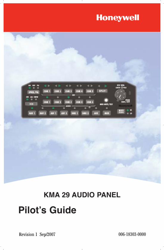
Pilot’s Guide
KMA 29 AUDIO PANEL
n
Revision 1 Sep/2007 006-18303-0000
KMA 29 PG Front Cover 9/7/07 2:08 PM Page 1
The information contained in this manual is for reference use only. If anyinformation contained herein conflicts with similar information con-tained in the Airplane Flight Manual Supplement, the information in theAirplane Flight Manual Supplement shall take precedence.
WARNING
The enclosed technical data is eligible for export under LicenseDesignation NLR and is to be used solely by the individual/organizationto whom it is addressed. Diversion contrary to U.S. law is prohibited.
COPYRIGHT NOTICE
Copyright © 2006, 2007 Honeywell International Inc. All rightsreserved.
Reproduction of this publication or any portion thereof by any means withoutthe express written permission of Honeywell International Inc. is prohibited. Forfurther information contact Aerospace Technical Publications; HoneywellBusiness & General Aviation; One Technology Center; 23500 West 105thStreet; Olathe, Kansas 66061. Telephone: (913) 712-0400.
KMA 29 PG Front Cover 9/7/07 2:08 PM Page 2
R-1
Revision History and Instructions
Manual KMA 29 Audio Panel Pilot’s Guide
Revision 1, September 2007
Part Number 006-18303-0000
Summary
Added paragraphs on dual KMA 29 operation on page 12.
Updated instructions on the soft mute inhibit on page 17.
R-2
Revision History and Instructions
Manual KMA 29 Audio Panel Pilot’s Guide
Revision 0, February 2006
Part Number 006-18303-0000
Summary
This is the original release of this publication.
INTRODUCTION . . . . . . . . . . . . . . . . . . . . . . . . . . . . . . . . . . . . . . . . . . . . . . 1
ACRONYMS AND ABBREVIATIONS . . . . . . . . . . . . . . . . . . . . . . . . . . . 2
AUDIO PANEL DESCRIPTION . . . . . . . . . . . . . . . . . . . . . . . . . . . . . . . . . 3
AUDIO PANEL CONTROLS . . . . . . . . . . . . . . . . . . . . . . . . . . . . . . . . . . . . 5
SPKR/PA (SPEAKER/PASSENGER ADDRESS) SWITCH . . . . . . . . . . . 6
COM MIC (MICROPHONE) SELECTOR BUTTONS . . . . . . . . . . . . . . . . 6
SPLIT MODE BUTTON . . . . . . . . . . . . . . . . . . . . . . . . . . . . . . . . . . . . . 7
CREW/PAX ICS VOL KNOB AND PUSH EMG/OFF SWITCH . . . . . . . . . 8
CREW/PAX ICS VOL (Crew/Passenger Intercom System
Volume) Knob . . . . . . . . . . . . . . . . . . . . . . . . . . . . . . . . . . . . . . . . . 8
PUSH EMG/OFF (Power On and Emergency/Off) Switch . . . . . . . . . . 8
ICS (INTERCOM SYSTEM) BUTTON . . . . . . . . . . . . . . . . . . . . . . . . . . 8
COM AUDIO SELECTOR BUTTONS . . . . . . . . . . . . . . . . . . . . . . . . . . . 9
NAVIGATION RADIO AUDIO (NAV, ADF, DME, AUX AND MKR)SELECTOR BUTTONS . . . . . . . . . . . . . . . . . . . . . . . . . . . . . . . . . . . . . 9
NAV1, NAV 2, ADF 1, ADF 2, DME 1 AND DME 2 Buttons . . . . . . . . 9
AUX Button . . . . . . . . . . . . . . . . . . . . . . . . . . . . . . . . . . . . . . . . . . . 9
MKR Button . . . . . . . . . . . . . . . . . . . . . . . . . . . . . . . . . . . . . . . . . . . 9
MKR SENS (MARKER BEACON SENSITIVITY) BUTTON . . . . . . . . . . 10
MKR MUTE/TEST (MARKER BEACON MUTE/TEST) BUTTON . . . . . . 10
AUDIO PANEL OPERATION . . . . . . . . . . . . . . . . . . . . . . . . . . . . . . . . . . 11
COM MICROPHONE OPERATION . . . . . . . . . . . . . . . . . . . . . . . . . . . . 11
COMMUNICATION AND NAVIGATION AUDIO OPERATION . . . . . . . . 12
DUAL KMA 29 OPERATION . . . . . . . . . . . . . . . . . . . . . . . . . . . . . . . . 12
EMERGENCY OPERATION . . . . . . . . . . . . . . . . . . . . . . . . . . . . . . . . . 12
MARKER BEACON OPERATION . . . . . . . . . . . . . . . . . . . . . . . . . . . . . 13
SPLIT MODE OPERATION . . . . . . . . . . . . . . . . . . . . . . . . . . . . . . . . . 14
Table of Contents
Rev. 1Sep/07 KMA 29 Audio Panel Pilot’s Guide i
INTERCOM OPERATION . . . . . . . . . . . . . . . . . . . . . . . . . . . . . . . . . . 15
ENTERTAINMENT SYSTEM OPERATION . . . . . . . . . . . . . . . . . . . . . . 16
Entertainment Soft Mute and Soft Mute Inhibit Modes . . . . . . . . . 17
TELEPHONE MODE OPERATION . . . . . . . . . . . . . . . . . . . . . . . . . . . . 18
Table of Contents
Rev. 1Sep/07KMA 29 Audio Panel Pilot’s Guideii
INTRODUCTION
All of us at Honeywell congratulate you on choosing this product. Youare now the owner of an outstanding audio system. We understand thatyou probably can’t wait to see it in action, but before you try to use itplease take the time to read through this manual and understand itsmany interesting and useful features. Time spent in familiarizing your-self with your new KMA 29 unit will be more than repaid by trouble-freeoperation later.
This Pilot’s Guide will be of great help to you. It is written in plain, sim-ple English and it assumes that you are not an experienced user of theaudio system. If you are experienced, then even better. It is designedso you can start at the front of the manual and progress in the orderpresented; however, you may want to skip around and learn things inyour own order.
Throughout this manual, it is assumed that the pilot sits on the left sideof the aircraft and the copilot sits on the right side. Any reference to aleft arrow indication refers to the pilot side and a right arrow indicationrefers to the copilot side.
Introduction
1KMA 29 Audio Panel Pilot’s GuideRev. 0Feb/06
N
ACRONYMS AND ABBREVIATIONS
ADF: Automatic Direction Finder
AUX: Auxiliary
COM: Communication
DME: Distance Measuring Equipment
EMG: Emergency
HI: High
ICS: Intercom System
ILS: Instrument Landing System
ISO: Isolated
LED: Light Emitting Diode
LO: Low
MIC: Microphone
MKR: Marker
NAV: Navigation
PA: Passenger Address
PAX: Passenger
PFD: Primary Flight Display
PTT: Push-to-Talk
SENS: Sensitivity
SPKR: Speaker
TAWS: Terrain Awareness Warning System
VHF: Very High Frequency
VOL: Volume
VOX: Voice Activation
Introduction
2 KMA 29 Audio Panel Pilot’s GuideRev. 0Feb/06
N
AUDIO PANEL DESCRIPTION
The KMA 29 audio control panel provides audio system control for thecockpit crew and passengers. The panel also provides an interface tothe passenger address (PA) system and aural warning system. Theaudio panel also includes a marker beacon receiver.
The audio panel is used to make audio selections for all audio commu-nications to and from the cockpit crew. The audio panel receives inputsfrom all audio communication channels and aural warnings. Audio out-puts from the panel include a cockpit speaker and headphone jacks.Noise-canceling headsets can be used with the audio panel.
The audio panel provides the following functions:
• Speaker control
• Five (5) very high frequency (VHF) communication (COM) trans-ceivers
• Split single panel or dual panel (independent) operation
• Intercom system operation with automatic voice activation (VOX)
• Eight (8) navigation receivers as follows:
- Two (2) navigation (NAV)
- Two (2) automatic direction finder (ADF)
- Two (2) distance measuring equipment (DME)
- One (1) auxiliary (AUX)
- One (1) marker beacon (MKR).
• Marker beacon mute/test and sense control
• Processing and routing of the aural warnings generated from exter-nal sources or systems
• Four (4) unswitched audio inputs
• Entertainment system (optional)
• Telephone operation (optional).
Audio Panel Description
3KMA 29 Audio Panel Pilot’s GuideRev. 0Feb/06
N

Audio Panel Description
There are four unswitched inputs (aircraft hard-wired and configured)available for traffic or terrain awareness warning system (TAWS),autopilot disconnect, and/or radar altimeter warning. The audio panelalways supplies the audio from one or two of the audio inputs to thepilot’s and copilot’s headset and cockpit speakers outputs during normaloperation.
Momentary push-button switches are used to select one of the COMtransceivers for the pilot and copilot position, which allows radio trans-mission. In the Split Mode, the pilot has the ability to transmit on oneCOM, while the copilot can transmit on another COM. A fail-safe modeconnects the pilot headphone and microphone to COM 1 if power isremoved for any reason, or if the power switch is placed in the OFF(fail-safe) position.
A six-station VOX intercom is included in the KMA 29 system. This sys-tem has a patented IntelliVox® circuitry that eliminates manual adjust-ments. The system contains six separate VOX microphone circuits andonly opens the microphone channel that is in use.
The intercom system incorporates pilot isolate mode, all crew mode,two independent stereo music inputs with Soft Mute, and light emittingdiode (LED) indications. Intercom control is through a concentric frontpanel volume control and a push-button intercom mode switch. Thesmall volume knob controls the intercom level for the pilot and copilotwhile the large knob controls the passenger intercom volume. The inter-com squelch is automatic.
A marker beacon receiver is integrated in the KMA 29 audio panel. Thisprovides the necessary marker beacon signal outputs to the display andaudio indications necessary for an instrument landing system (ILS)approach. The push-button labeled MKR allows the pilot to select themarker beacon mode of operation. The pilot can then select either highor low sensitivity using the marker beacon sensitivity (MKR SENS) but-ton or mute the marker beacon audio by pushing the MUTE button. Themarker beacon can be tested by selecting and holding the MKRMUTE/TEST button for five seconds.
The aircraft system uses the marker beacon receiver information sup-plied by the audio panel to generate status displays.
4 KMA 29 Audio Panel Pilot’s GuideRev. 0Feb/06
N
Audio Panel Controls
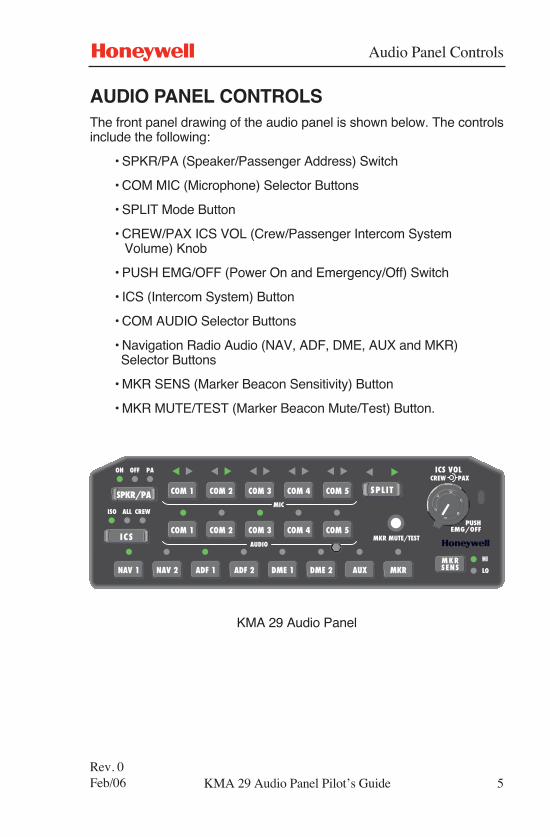
AUDIO PANEL CONTROLSThe front panel drawing of the audio panel is shown below. The controlsinclude the following:
• SPKR/PA (Speaker/Passenger Address) Switch
• COM MIC (Microphone) Selector Buttons
• SPLIT Mode Button
• CREW/PAX ICS VOL (Crew/Passenger Intercom System Volume) Knob
• PUSH EMG/OFF (Power On and Emergency/Off) Switch
• ICS (Intercom System) Button
• COM AUDIO Selector Buttons
• Navigation Radio Audio (NAV, ADF, DME, AUX and MKR) Selector Buttons
• MKR SENS (Marker Beacon Sensitivity) Button
• MKR MUTE/TEST (Marker Beacon Mute/Test) Button.
KMA 29 Audio Panel
5KMA 29 Audio Panel Pilot’s GuideRev. 0Feb/06
N
���������� �
��� ������
��
��
������� �� ��
��� �� �� �
�� ���
���� N
���
����� ����� ����� ����� �����
����� ����� ����� ����� �����
���� ���� ���� ���� �� �� �� �� ������ �����
����
���
����
Audio Panel Controls
6Rev. 0Feb/06
N
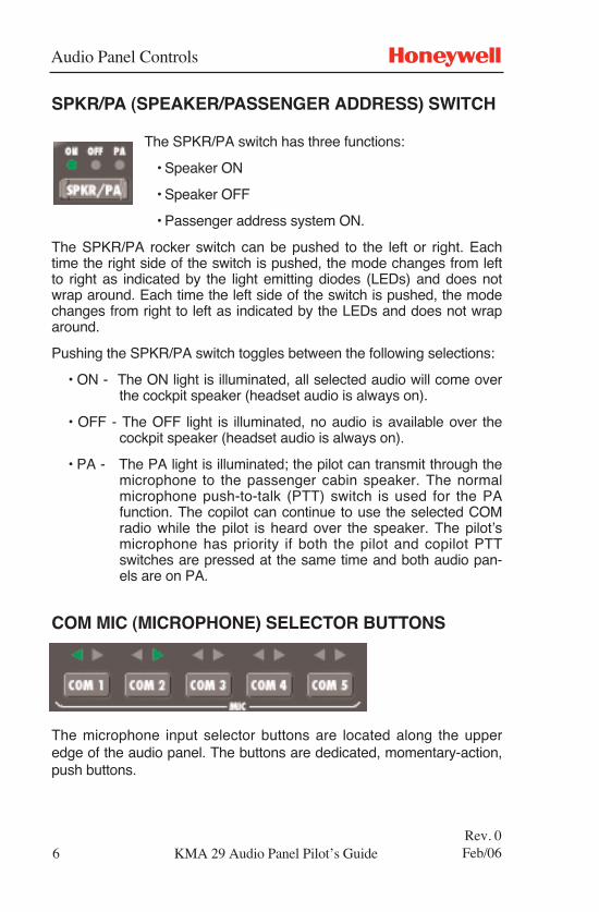
SPKR/PA (SPEAKER/PASSENGER ADDRESS) SWITCH
The SPKR/PA switch has three functions:
• Speaker ON
• Speaker OFF
• Passenger address system ON.
The SPKR/PA rocker switch can be pushed to the left or right. Eachtime the right side of the switch is pushed, the mode changes from leftto right as indicated by the light emitting diodes (LEDs) and does notwrap around. Each time the left side of the switch is pushed, the modechanges from right to left as indicated by the LEDs and does not wraparound.
Pushing the SPKR/PA switch toggles between the following selections:
• ON - The ON light is illuminated, all selected audio will come overthe cockpit speaker (headset audio is always on).
• OFF - The OFF light is illuminated, no audio is available over thecockpit speaker (headset audio is always on).
• PA - The PA light is illuminated; the pilot can transmit through themicrophone to the passenger cabin speaker. The normalmicrophone push-to-talk (PTT) switch is used for the PAfunction. The copilot can continue to use the selected COMradio while the pilot is heard over the speaker. The pilot’smicrophone has priority if both the pilot and copilot PTTswitches are pressed at the same time and both audio pan-els are on PA.
COM MIC (MICROPHONE) SELECTOR BUTTONS
The microphone input selector buttons are located along the upperedge of the audio panel. The buttons are dedicated, momentary-action,push buttons.
KMA 29 Audio Panel Pilot’s Guide
Audio Panel Controls
7Rev. 0Feb/06
N
The COM 1 through COM 5 MIC buttons are used to select the associ-ated radio transmitter. The receiver audio for the selected transmitter isautomatically selected.
A lighted arrow located above each button indicates that the button hasbeen pressed and that the mode is active for the left (pilot) side, right(copilot) side, or both sides. This depends upon the mode of the audiopanel operation split or duplex mode. Refer to the Split Mode Operationin this Pilot’s Guide for additional information on the Split Mode.
COM 5 can be configured for duplex, which simulates the operation of atelephone. Refer to the Telephone Mode Operation in this Pilot’s Guidefor additional information on the Telephone Mode.
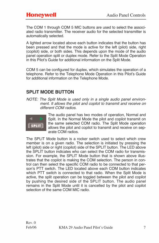
SPLIT MODE BUTTON
NOTE: The Split Mode is used only in a single audio panel environ-ment. It allows the pilot and copilot to transmit and receive ondifferent COM radios.
The audio panel has two modes of operation, Normal andSplit. In the Normal Mode the pilot and copilot transmit onthe same selected COM radio. The Split Mode operationallows the pilot and copilot to transmit and receive on sep-arate COM radios.
The SPLIT Mode button is a rocker switch used to select which crewmember is on a given radio. The selection is initiated by pressing theleft (pilot) side or right (copilot) side of the SPLIT button. The LED abovethe SPLIT button indicates who can select the COM radio for transmis-sion. For example, the SPLIT Mode button that is shown above illus-trates that the copilot is making the COM selection. The person in con-trol can then select the specific COM radio to be connected to that per-son’s PTT switch. The LED located above each COM button indicateswhich PTT switch is connected to that radio. When the Split Mode isactive, the split operation can be toggled between the pilot and copilotby pushing the desired side of the SPLIT button. The audio panelremains in the Split Mode until it is cancelled by the pilot and copilotselection of the same COM MIC radio.
KMA 29 Audio Panel Pilot’s Guide
Audio Panel Controls
8Rev. 0Feb/06
N
CREW/PAX ICS VOL KNOB AND PUSH EMG/OFFSWITCH
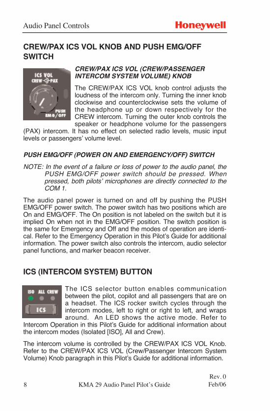
CREW/PAX ICS VOL (CREW/PASSENGERINTERCOM SYSTEM VOLUME) KNOB
The CREW/PAX ICS VOL knob control adjusts theloudness of the intercom only. Turning the inner knobclockwise and counterclockwise sets the volume ofthe headphone up or down respectively for theCREW intercom. Turning the outer knob controls thespeaker or headphone volume for the passengers
(PAX) intercom. It has no effect on selected radio levels, music inputlevels or passengers’ volume level.
PUSH EMG/OFF (POWER ON AND EMERGENCY/OFF) SWITCH
NOTE: In the event of a failure or loss of power to the audio panel, thePUSH EMG/OFF power switch should be pressed. Whenpressed, both pilots’ microphones are directly connected to theCOM 1.
The audio panel power is turned on and off by pushing the PUSHEMG/OFF power switch. The power switch has two positions which areOn and EMG/OFF. The On position is not labeled on the switch but it isimplied On when not in the EMG/OFF position. The switch position isthe same for Emergency and Off and the modes of operation are identi-cal. Refer to the Emergency Operation in this Pilot’s Guide for additionalinformation. The power switch also controls the intercom, audio selectorpanel functions, and marker beacon receiver.
ICS (INTERCOM SYSTEM) BUTTON
The ICS selector button enables communicationbetween the pilot, copilot and all passengers that are ona headset. The ICS rocker switch cycles through theintercom modes, left to right or right to left, and wrapsaround. An LED shows the active mode. Refer to
Intercom Operation in this Pilot’s Guide for additional information aboutthe intercom modes (Isolated [ISO], All and Crew).
The intercom volume is controlled by the CREW/PAX ICS VOL Knob.Refer to the CREW/PAX ICS VOL (Crew/Passenger Intercom SystemVolume) Knob paragraph in this Pilot’s Guide for additional information.
KMA 29 Audio Panel Pilot’s Guide
Audio Panel Controls
9Rev. 0Feb/06
N
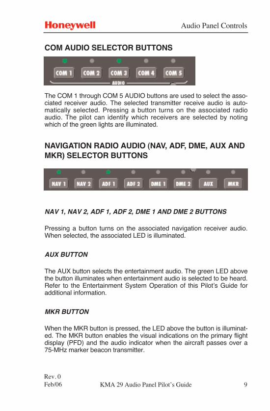
COM AUDIO SELECTOR BUTTONS
The COM 1 through COM 5 AUDIO buttons are used to select the asso-ciated receiver audio. The selected transmitter receive audio is auto-matically selected. Pressing a button turns on the associated radioaudio. The pilot can identify which receivers are selected by notingwhich of the green lights are illuminated.
NAVIGATION RADIO AUDIO (NAV, ADF, DME, AUX ANDMKR) SELECTOR BUTTONS
NAV 1, NAV 2, ADF 1, ADF 2, DME 1 AND DME 2 BUTTONS
Pressing a button turns on the associated navigation receiver audio.When selected, the associated LED is illuminated.
AUX BUTTON
The AUX button selects the entertainment audio. The green LED abovethe button illuminates when entertainment audio is selected to be heard.Refer to the Entertainment System Operation of this Pilot’s Guide foradditional information.
MKR BUTTON
When the MKR button is pressed, the LED above the button is illuminat-ed. The MKR button enables the visual indications on the primary flightdisplay (PFD) and the audio indicator when the aircraft passes over a75-MHz marker beacon transmitter.
KMA 29 Audio Panel Pilot’s Guide
Audio Panel Controls
10Rev. 0Feb/06
N
When the LED above the MKR button is OFF, the marker audio ismuted. The visual indications on the PFD will still operate when the air-craft passes over the marker.
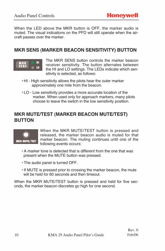
MKR SENS (MARKER BEACON SENSITIVITY) BUTTON
The MKR SENS button controls the marker beaconreceiver sensitivity. The button alternates betweenthe HI and LO settings. The LEDs indicate which sen-sitivity is selected, as follows:
• HI - High sensitivity allows the pilots hear the outer marker approximately one mile from the beacon.
• LO - Low sensitivity provides a more accurate location of the marker. When used only for approach markers, many pilots choose to leave the switch in the low sensitivity position.
MKR MUTE/TEST (MARKER BEACON MUTE/TEST)BUTTON
When the MKR MUTE/TEST button is pressed andreleased, the marker beacon audio is muted for thatmarker beacon. The muting continues until one of thefollowing events occurs:
• A marker tone is detected that is different from the one that was present when the MUTE button was pressed.
• The audio panel is turned OFF.
• If MUTE is pressed prior to crossing the marker beacon, the mute will be held for 60 seconds and then timeout.
When the MKR MUTE/TEST button is pressed and held for five sec-onds, the marker beacon discretes go high for one second.
KMA 29 Audio Panel Pilot’s Guide
KMA 29 Audio Panel Pilot’s Guide
Audio Panel Operation
AUDIO PANEL OPERATIONThe audio panel receives audio from remote radio units, decodes theaudio, controls the gain (volume) and routing of the various channels,filters audio signals, and output the audio to various speakers and head-phones. It controls microphone inputs to various radios, intercom andpassenger address systems. Amplifiers are included for driving head-phones and speakers.
The audio panel also has inputs for intercom, crew annunciator, crewcommunication, hot microphones and full time emergency warninginputs from aircraft systems.
COM MICROPHONE OPERATION
When a microphone selector button is selected and PTT switch isenabled, the pilot’s or copilot’s microphone signal is routed to thatradio’s microphone input. Pressing the MIC selector button to enable aparticular COM also causes the audio for that particular COM to beautomatically enabled.
Above each microphone input selector button are left and right arrowLEDs that show the status of the respective COM transceiver. The leftarrow is lit when that particular COM transceiver is assigned to the pilot.The right arrow is lit when that particular COM transceiver is assigned tothe copilot. Only one COM microphone output can be active for the pilotor copilot at a time with two exceptions. The two exceptions are SplitMode and Telephone Mode (or Duplex Mode) operation. Refer to SplitMode Operation and Telephone Mode Operation in this Pilot’s Guide foradditional information.
When switching between COMs, such as from COM 1 to COM 2 (whileCOM 2 AUDIO has been selected), COM 1 audio will continue to beheard. This eliminates the need for the pilot to switch the COM 1 audioback on, if desired.
When switching from COM 1 to COM 2 (while COM 2 AUDIO has notbeen selected), COM 1 audio is switched off. This means that switchingthe COMs does not affect the selection of the COM receiver audio.
The audio panel gives priority to the pilot’s PTT switch. If the copilot istransmitting and the pilot presses the PTT switch, the pilot’s microphoneis heard over the selected COM transmitter.
11Rev. 0Feb/06
N
Audio Panel Operation
12Rev. 1Sep/07
N
COMMUNICATION AND NAVIGATION AUDIOOPERATION
Pressing any of the communication (COM) or navigation (NAV, ADF,DME, AUX, or MKR) audio selector buttons enables the associatedaudio and the LED above the button is lit. Pressing the same audioselector button again turns the audio for that channel and the LEDabove the button off. The pilot and copilot can select and listen to morethan one communication or navigation audio at a given time.
DUAL KMA 29 OPERATION
When two KMA 29 audio panels are installed, both have access to thecommunications transceivers. When both panels have selected thesame transmitter, the KMA 29 designated as the pilot position has prior-ity.
Indication arrows above the microphone selectors indicate which sidehas selected the radio for transmit. Offside radio indication is user selec-table. When the offside indication is off, only the mic select arrow for theKMA 29 position is active. When on, the pilot can see which radio thecopilot has selected for transmit, and vice versa, by noting which of thearrows is illuminated.
To toggle the offside transmit selection indication, press the right side ofthe SPLIT button three (3) times within one and a half (1 1/2) seconds.When the mode is activated, the NAV 1 indicator blinks once. When themode is toggled off, the NAV 1 indicator blinks twice. This moderemains in effect until changed by the user, including power cycles.
EMERGENCY OPERATION
NOTE: In the event of a failure or loss of power to the audio panel, thePUSH EMG/OFF power switch should be pressed. Whenpressed, both pilots’ microphones are directly connected to theCOM 1.
The PUSH EMG/OFF (Power On and Emergency/Off) switch is a twoposition switch. One position is On (implied) and the other position isEMG/OFF. The Emergency and Off modes of operation are identical.
In the EMG/OFF position, the pilot is connected directly to COM 1 trans-mit and COM 1 receive through the headphones only. This allows com-
KMA 29 Audio Panel Pilot’s Guide
Audio Panel Operation
13Rev. 1Sep/07
N
KMA 29 Audio Panel Pilot’s Guide
munication capability regardless of the condition of the unit. Any timepower is removed or turned off, the audio selector is placed in the EMGmode.
In the EMG mode, one or two of the unswitched audio inputs are sup-plied to the pilot headset. Also, in the EMG mode, audio signals are pre-sent in only one ear of a stereo headset.
MARKER BEACON OPERATION
The marker beacon receiver uses visual and audio indicators to alertthe crew when the aircraft passes over a 75 MHz transmitter. There is aservice adjustment located on the unit for ground maintenance to adjustthe marker audio volume level.
The outer, middle and inner marker indications are shown on an exter-nal display. The audio panel supplies a 400-Hz “dash” audio tone for theouter marker. The outer marker tone is keyed at a rate of twotones/flashes per second when the aircraft is in the range of the outermarker beacon. The panel provides a 1300-Hz tone for the middlemarker, which is keyed alternately with short “dot” and long “dash”bursts at 95 combinations per minute. The audio panel supplies a 3000-Hz “dot” tone for the inner marker. The inner marker tone is keyed at arate of six times per second.
The MKR SENS button is used to set the receiver sensitivity and to testthe marker beacon. Use high (HI) sensitivity initially. This allows you tohear the outer marker beacon about a mile out. Then push the MKRSENS button to switch into the low (LO) sensitivity mode. Low sensitivi-ty gives you a more accurate location of the marker. Many pilots chooseto leave the button in the low sensitivity mode.
Pressing and releasing the MKR MUTE/TEST button causes the mark-er audio to mute for that beacon. The muting continues until one of thefollowing events occurs:
1. A marker tone is detected that is different from the one that waspresent when MUTE was initiated or if the same tone returns after adelay. (The delay accounts for a tone that fades and then comesright back. The MUTE is reset if the aircraft is flown out of the cur-rent tone and then back in.)
2. The audio panel is turned OFF.
3. If MUTE is pressed prior to crossing the marker beacon, the mutewill continue for 60 seconds and then timeout.
Audio Panel Operation
14Rev. 1Sep/07
N
KMA 29 Audio Panel Pilot’s Guide
Pressing and holding the MKR MUTE/TEST button for five secondscauses the marker beacon discretes to go high for one second in orderto test the marker beacon. The marker beacon annunciations areshown on an external display.
SPLIT MODE OPERATION
NOTE: The Split Mode is used only in a single audio panel environ-ment. It allows the pilot and copilot to transmit and receive ondifferent COM radios.
The typical Split Mode operation is as follows:
1. Both pilot and copilot are on COM 1 microphone (as indicated byboth the left and right arrows being lit on COM 1).
2. To split to COM 2, the pilot pushes the pilot side (left side) of theSPLIT button. The LED above the pilot side of the SPLIT buttonlights, indicating the SPLIT mode is initiated.
3. The pilot then presses COM 2 microphone. The pilot arrow indicatorabove the COM 2 microphone lights. The pilot is now connected tothe COM 2 microphone.
4. The pilot access indicator on the COM 1 microphone turns off, leav-ing the copilot with sole access to the COM 1 microphone.
5. The intercom system (ICS) modes changes to isolated (ISO). Thepilot indicator over the SPLIT button turns off.
When the Split Mode is activated, the intercom automatically reverts tothe Isolated Mode. However, the ICS button can be used to enable theCrew and All modes for intercommunications. To exit the Split Mode,the pilot and copilot should select the same COM MIC button.
The Split Mode operation permits one user to enable both COM 5 andany other COM (1 thru 4), while simultaneously allowing the other userto select one of the remaining COMs (1 thru 4). The following is anexample of this configuration:
• The pilot selects COM 5 (Telephone) and COM 1 MIC(Microphone).
• The copilot enables the Split Mode by pressing the right side(copilot side) of the SPLIT button.
• The copilot then selects COM 2 MIC.
Audio Panel Operation
15Rev. 0Feb/06
N
INTERCOM OPERATION
The intercom system is an IntelliVox® automatic voice activated system.The IntelliVox® circuitry eliminates the need for manual adjustments ofthe squelch. Through three individual signal processors, the ambientnoise appearing in all six microphones is constantly being sampled.Non-voice signals are blocked. When someone speaks, the microphonecircuit opens, placing their voice on the intercom. The system isdesigned to block continuous tones, therefore, someone humming orwhistling in monotone may be blocked after a few moments.
For consistent performance, any headset microphone must be placedwithin 1/4 inch of your lips, preferably against them. It is also a goodidea to keep the microphone out of a direct wind path. Moving yourhead through a vent air stream may cause the IntelliVox® to openmomentarily. This is normal.
For optimum microphone performance, Honeywell recommends instal-lation of a Microphone Muff Kit from Oregon Aero (1-800-888-6910) orequivalent. This will not only optimize VOX acoustic performance, butwill also improve the overall clarity of all your communications.
The volume control for the intercom is the CREW/PAX ICS VOL knob.Refer to the CREW/PAX ICS VOL (Crew/Passenger Intercom SystemVolume) Knob paragraph in this Pilot’s Guide for additional information.
All passenger headsets are connected in parallel. If a monaural headsetis plugged in to a KMA 29 installation, one channel is shorted. Althoughno damage will occur to the unit, all passengers will lose one channelunless they switch to the MONO mode on the headset.
The intercom modes are given in the following table:
KMA 29 Audio Panel Pilot’s Guide
Audio Panel Operation
16Rev. 0Feb/06
N
ENTERTAINMENT SYSTEM OPERATION
The KMA 29 audio panel has provisions for two separate entertainmentinputs. Entertainment 1 (or Music 1) feeds the pilot and copilot posi-tions, which operate independently in the audio panel. The CREW/PAXICS VOL knob does not affect the music level. Most general aviationheadsets today have built-in volume controls; therefore, the music vol-ume can be adjusted at the headset. Entertainment 2 (or Music 2) is fedto the passengers. The passenger music also operates independentlyof the crew (Music 1).
KMA 29 Audio Panel Pilot’s Guide
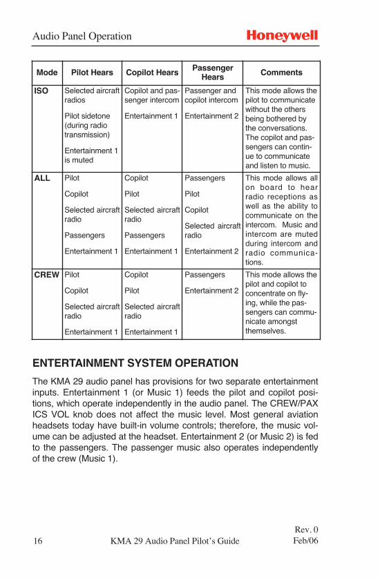
Mode Pilot Hears Copilot Hears PassengerHears Comments
ISO Selected aircraftradios
Pilot sidetone(during radiotransmission)
Entertainment 1is muted
Copilot and pas-senger intercom
Entertainment 1
Passenger andcopilot intercom
Entertainment 2
This mode allows thepilot to communicatewithout the othersbeing bothered bythe conversations.The copilot and pas-sengers can contin-ue to communicateand listen to music.
ALL Pilot
Copilot
Selected aircraftradio
Passengers
Entertainment 1
Copilot
Pilot
Selected aircraftradio
Passengers
Entertainment 1
Passengers
Pilot
Copilot
Selected aircraftradio
Entertainment 2
This mode allows allon board to hearradio receptions aswell as the ability tocommunicate on theintercom. Music andintercom are mutedduring intercom andradio communica-tions.
CREW Pilot
Copilot
Selected aircraftradio
Entertainment 1
Copilot
Pilot
Selected aircraftradio
Entertainment 1
Passengers
Entertainment 2
This mode allows thepilot and copilot toconcentrate on fly-ing, while the pas-sengers can commu-nicate amongstthemselves.
Audio Panel Operation
17Rev. 1Sep/07
N
While in the intercom ISO mode, Entertainment 1 is muted for the pilot.The copilot hears Entertainment 1 at a normal level. The music auto-matically mutes when either the copilot or passengers speak and thengradually returns to the original listening level when the intercom orradio conversation ceases. The pilot does not mute the music while inthe ISO mode if the PTT switch is pressed to transmit or if the pilotspeaks while on the phone.
When in the intercom ALL mode, Music 1 mutes automatically with aSoft Mute, or can be placed in Soft Mute Inhibit Mode, which isdescribed below. The passengers can disable their music muting withan external switch that may have been installed during installation.
While in the intercom CREW mode, the pilot and copilot hearEntertainment 1, while the passengers hear Entertainment 2.
ENTERTAINMENT SOFT MUTE AND SOFT MUTE INHIBIT MODES
The Soft Mute feature assures that the aircraft radio transmissions arenot missed due to playing entertainment. When there is radio receptionor intercom conversation, the music level is decreased gradually to avery low level. When the radio or intercom traffic ceases, the level grad-ually returns back to normal.
The KMA 29 audio panel is equipped with a Soft Mute inhibit capability.This allows the music to continue uninterrupted by intercom or radiotraffic when the cockpit workload is appropriate. To inhibit the Soft Mute,press the MKR MUTE/TEST button three (3) times within one and a half(1 1/2) seconds. The NAV 1 indicator blinks once to indicate that theSoft Mute inhibit is on, and blinks twice when the Soft Mute inhibit modeis turned off (music mutes with radio or intercom conversation).
The passenger music, which is Entertainment 2, can be placed in themute inhibit mode by a switch that is installed in the aircraft.
KMA 29 Audio Panel Pilot’s Guide
Audio Panel Operation
TELEPHONE MODE OPERATION
When enabled in the installation, COM 5 serves as a full duplex inter-face for telephone systems. When interfaced with specific aircraftapproved FAA/FCC cellular telephone equipment, the audio panel canserve as an audio control and distribution center. The audio panel actsas an audio interface between aircraft headphone and microphones andtelephone.
The pilot selects telephone by selecting COM 5 on the audio panel. Thecopilot and passengers each have an external hook switch to allowthem to use the telephone.
When COM 5 is configured for duplex and is selected, the pilot micro-phone and headphones are connected to the phone. The pilot PTTswitches the pilot microphone to the selected COM transceiver andallows continued aircraft communications. The copilot is able to transmiton the other selected radio with the copilot PTT switch as well.
When the KMA 29 audio panel is configured for COM 5 duplex opera-tion, it functions as follows:
1. The pilot selects telephone by selecting COM 5 on the audio panel.
2. The copilot selects telephone using the external copilot hook switch.
3. The passengers select telephone using the external passengerhook switch.
NOTE: The use of non-aviation approved cellular telephone equipmentmay be prohibited by regulation. Honeywell is not responsiblefor unauthorized airborne use of cellular telephones. For air-borne use, the KMA 29 audio panel must be interfaced with anapproved system.
18Rev. 0Feb/06
N
KMA 29 Audio Panel Pilot’s Guide

KMA 29 PG Back Cover 9/7/07 2:06 PM Page 1

n
Honeywell AerospaceBusiness and General AviationHoneywell International Inc.One Technology Center23500 West 105th StreetOlathe, KS 66061Telephone: (913) 712-0400FAX: (913) 712-1302www.honeywell.com
006-18303-0000Rev. 1 09/07© 2006, 2007 Honeywell International Inc.
KMA 29 PG Back Cover 9/7/07 2:06 PM Page 2