KERB type SK - Stora-Drain|caniveaux-geulen ...imcoma.com/images/catalogues/Stora-Kerb 11-09...
12
® KERB type SK A combined KERB and CHANNEL drainage system IMC SK 13-07 EN
Transcript of KERB type SK - Stora-Drain|caniveaux-geulen ...imcoma.com/images/catalogues/Stora-Kerb 11-09...

®
KERB type SK
A combined KERB and CHANNEL drainage system
IMC
SK 1
3-0
7 E
N
KERBEN 1433Class D400
KERB SK 100
KERB - type SK2 KERB type SK
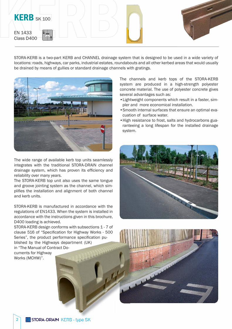
The channels and kerb tops of the STORA-KERB system are produced in a high-strength polyester concrete material. The use of polyester concrete gives several advantages such as:
Lightweight components which result in a faster, sim-•pler and more economical installation.Smooth internal surfaces that ensure an optimal eva-•cuation of surface water. High resistance to frost, salts and hydrocarbons gua-•ranteeing a long lifespan for the installed drainage system.
STORA-KERB is a two-part KERB and CHANNEL drainage system that is designed to be used in a wide variety of locations: roads, highways, car parks, industrial estates, roundabouts and all other kerbed areas that would usually be drained by means of gullies or standard drainage channels with gratings.
The wide range of available kerb top units seamlessly integrates with the traditional STORA-DRAIN channel drainage system, which has proven its effi ciency and reliability over many years. The STORA-KERB top unit also uses the same tongue and groove jointing system as the channel, which sim-plifi es the installation and alignment of both channel and kerb units.
STORA-KERB is manufactured in accordance with the regulations of EN1433. When the system is installed in accordance with the instructions given in this brochure, D400 loading is achieved.STORA-KERB design conforms with subsections 1 - 7 of clause 516 of “Specifi cation for Highway Works - 500 Series”, the product performance specifi cation pu-blished by the Highways department (UK) in “The Manual of Contract Do-cuments for Highway Works (MCHW)”.

KERB
KERB - type SK
EN 1433Class D400
KERB SK 100
3
STORA-KERB EXAMPLE RUNS
Access Unitevery +/- 25m
Access Unitat start of the run
Gully Top
Channels 010 - 020 - 030Length 1m or 0,5m
Constant invert depth or stepped-fall systemGully Base
End
cap
Cha
nnel
Ker
b
EndcapK
erb
DropperLeft
1m long
Access Unitat start of the run
Gully Top
Channels 010 - 020 - 030Length 1m or 0,5m
Constant invert depth or stepped-fall systemGully Base
End
cap
Cha
nnel
Ker
b
EndcapK
erb
DropperRight
1m longCrossing Stone
0,5m long
Access Unitat start of the run
Gully Top
Channels 010 - 020 - 030Length 1m or 0,5m
Constant invert depth or stepped-fall systemGully Base
End
cap
Cha
nnel
Ker
b
Endcap
Kerb C
hannel
Access Unitat end of the run
Example 1 : straight run with gully installed at the end of the run.
Example 2 : straight run with crossing point and gully installed at the end of the run.
Example 3 : straight run with centrally located gully.
KERBEN 1433Class D400
KERB SK 100
KERB - type SK4
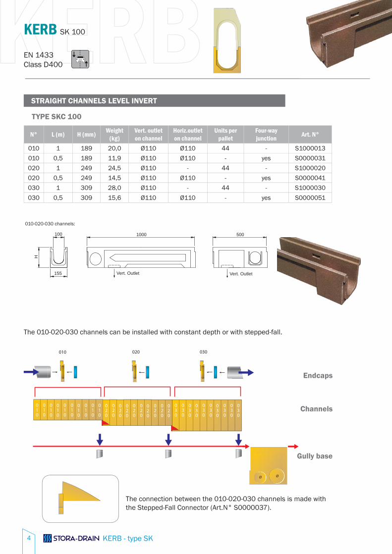
STRAIGHT CHANNELS LEVEL INVERT
N° L (m) H (mm) Weight(kg)
Vert. outlet on channel
Horiz.outlet on channel
Units per pallet
Four-way junction Art. N°
010 1 189 20,0 Ø110 Ø110 44 - S1000013
010 0,5 189 11,9 Ø110 Ø110 - yes S0000031
020 1 249 24,5 Ø110 - 44 - S1000020
020 0,5 249 14,5 Ø110 Ø110 - yes S0000041
030 1 309 28,0 Ø110 - 44 - S1000030
030 0,5 309 15,6 Ø110 Ø110 - yes S0000051
TYPE SKC 100
H
100 500 1000
155 Vert. Outlet Vert. Outlet
010-020-030 channels:
The 010-020-030 channels can be installed with constant depth or with stepped-fall.
Endcaps
Channels
Gully base
The connection between the 010-020-030 channels is made with the Stepped-Fall Connector (Art.N° S0000037).

KERB
KERB - type SK
EN 1433Class D400
KERB SK 100
5
KERB TOPS
Element L (m) H (mm) Weight (kg) Art. N°Kerb Top 0,5 220 15,7 SK500001
Access Unit 0,5 220 9,7 SK540001
Dropper Left 1 220-120 33,5 SK550101
Crossing Stone 0,5 120 15,0 SK550301
Dropper Right 1 120-220 33,5 SK550201
Radius 6-7m External 0,5 220 15,7 SK820005
Radius 8-10 External 0,5 220 15,7 SK820006
Radius 11-25 External 0,5 220 15,7 SK820007
Radius 11-25 Internal 0,5 220 15,7 SK820008
Blind Kerb 0,5 100 16,6 SK530001
Kerb Tops
Element L (m) H (mm) Weight (kg) Art. N°Grating (slot 20mm) 0,5 100 10,4 S2611101
Inspection Frame (Galv.) 0,5 100 3,2 S2612101
Inspection Lid 0,5 90 14,3 S2613101
Polyester Groove Grating
The kerb tops are installed on top of the channels, without the need for adhesives or mortar. The concrete surround fi lls the recesses on both sides of the kerb tops and ensures a solid installation.The kerb has a Half Battered (HB) profi le and the upstand is 120mm to match a standard HB 2 kerb profi le.The kerb tops should be installed directly adjacent to each other on top of the channel units. If there is a gap at the end of the run, it should be fi lled with a cut section of a standard or a blind kerb top (1). When installing the kerb tops, sliding the tops back and forth on the channel will wear the centring guides and ensure a perfect levelling and alignment (2).
220
H
120
1000
1 2
KERBEN 1433Class D400
KERB SK 100
KERB - type SK6
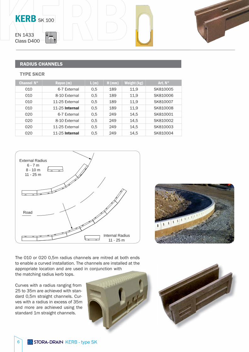
RADIUS CHANNELS
Channel N° Rayon (m) L (m) H (mm) Weight (kg) Art. N°010 6-7 External 0,5 189 11,9 SK810005
010 8-10 External 0,5 189 11,9 SK810006
010 11-25 External 0,5 189 11,9 SK810007
010 11-25 Internal 0,5 189 11,9 SK810008
020 6-7 External 0,5 249 14,5 SK810001
020 8-10 External 0,5 249 14,5 SK810002
020 11-25 External 0,5 249 14,5 SK810003
020 11-25 Internal 0,5 249 14,5 SK810004
TYPE SKCR
External Radius6 - 7 m
8 - 10 m11 - 25 m
Internal Radius11 - 25 m
Road
The 010 or 020 0,5m radius channels are mitred at both ends to enable a curved installation. The channels are installed at the appropriate location and are used in conjunction with the matching radius kerb tops.
Curves with a radius ranging from 25 to 35m are achieved with stan-dard 0,5m straight channels. Cur-ves with a radius in excess of 35m and more are achieved using the standard 1m straight channels.
j

KERB
KERB - type SK
EN 1433Class D400
KERB SK 100
7
KERB TOPS DETAILS
KERB TOP ACCESS UNIT BLIND KERB
DROPPER LEFT DROPPER RIGHT
CROSSING STONE RADIUS EXTERNAL RADIUS INTERNAL
124
500
100
155
500
20
490
95
150
500
20
POLYESTER GROOVE GRATING
INSPECTION FRAME & INSPECTION LIDGRATING
500
155
220
100
220
155
500
100
500
155
220
100
220
120
1000
100
220
100
120
1000
100
500
120
155
500
220
155
500
100
VAR.
220
155
500
100
VAR.
KERBEN 1433Class D400
KERB SK 100
KERB - type SK8
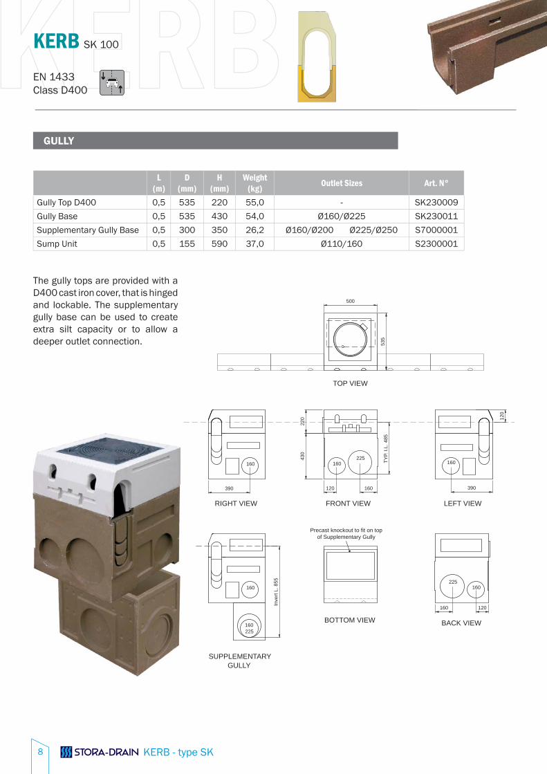
GULLY
L (m)
D (mm)
H (mm)
Weight(kg) Outlet Sizes Art. N°
Gully Top D400 0,5 535 220 55,0 - SK230009
Gully Base 0,5 535 430 54,0 Ø160/Ø225 SK230011
Supplementary Gully Base 0,5 300 350 26,2 Ø160/Ø200 Ø225/Ø250 S7000001
Sump Unit 0,5 155 590 37,0 Ø110/160 S2300001
The gully tops are provided with a D400 cast iron cover, that is hinged and lockable. The supplementary gully base can be used to create extra silt capacity or to allow a deeper outlet connection.
GULLYSUPPLEMENTARY
225160
160
RIGHT VIEW
160
160
TOP VIEW
225
BACK VIEW
225
BOTTOM VIEW
Precast knockout to fit on topof Supplementary Gully
LEFT VIEWFRONT VIEW
160160
160 390390 120
Inve
rt L.
855
160 120
120
TYP.
I.L.
485
220
430
535
500

KERB
KERB - type SK
EN 1433Class D400
KERB SK 100
9
ENDCAPS
Element N° H (mm)
Installationbefore/after
Weight(kg) Art. N° Integrated In-/Outlet
with gasket and PE cover plateEndcap Channel 010 195 channel n° 010 1,3 SE100032 Ø110
Endcap Channel 020 245 channel n° 020 1,5 SE100034 Ø110
Endcap Channel 030 295 channel n° 030 1,6 SE100035 Ø110
The endcaps for the channel and the kerb tops are installed separately.
The endcaps with integrated In-/Outlet for the 010-020-030 channels can be used with the PE insert to start or end the channel run. A PVC pipe can be inserted after removal of the PE insert and used to connect two channel runs or to create an outlet if a gully cannot be installed due to depth restrictions.
TYPE ECC
Element N° H (mm)
Installationbefore/after
Weight(kg) Art. N° Integrated In-/Outlet
with gasket and PE cover plateEndcap Kerb - 220 Kerb H=220 1,1 SK210020 -
TYPE ECK

KERBEN 1433Class D400
KERB SK 100
KERB - type SK10
STORA-KERB CAPACITY
The STORA-KERB is a fl exible and high capacity channel drainage system. The choice between the different available STORA-DRAIN drainage channels will be made based on the STORA-DRAIN capacity calculation program.
The graphs show the maximum allowable channel length for the given road or terrain width, assuming that the run is discharged into the standard Kerb Gully and is connected to a suitable outfall pipe diameter.
Please contact our technical department for detailed design assistance.
The water-holding capacity of the STORA-KERB: on 010 channels 25,80 litre/metre on 020 channels 31,50 litre/metre on 030 channels 37,20 litre/metre
CAPACITY
Leng
ht o
f the
cha
nnel
run
to th
e ou
tlet
Width of the surface
With 50 mm/h or 140 L/sec.ha
KERB
KERB - type SK
EN 1433Class D400
KERB SK 100
11
INSTALLATION & MAINTENANCE GUIDELINES
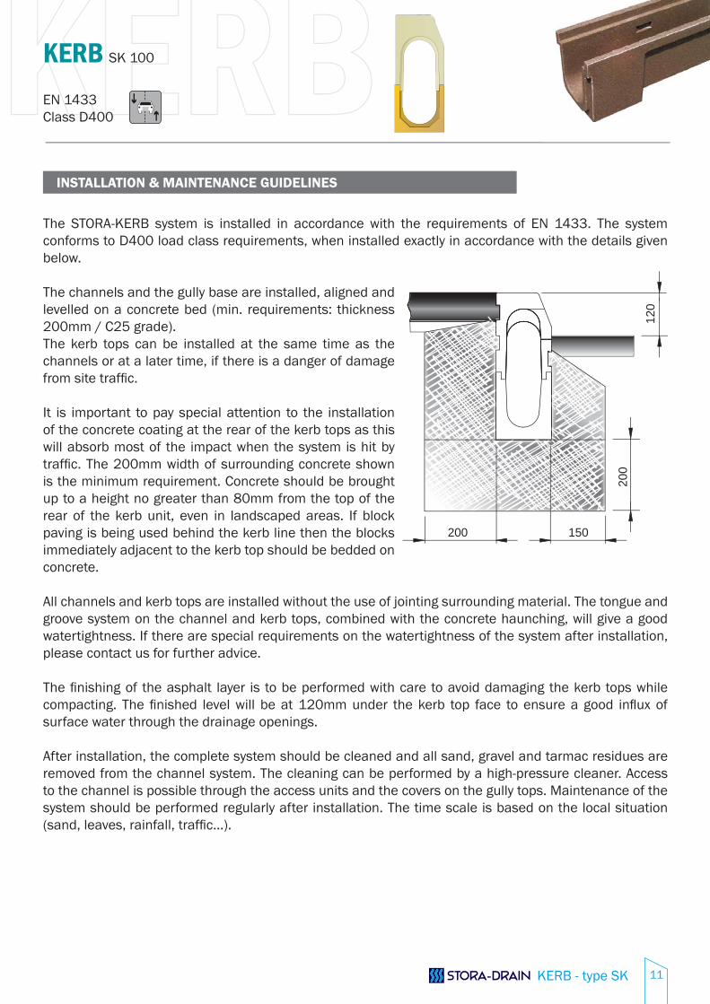
The STORA-KERB system is installed in accordance with the requirements of EN 1433. The system conforms to D400 load class requirements, when installed exactly in accordance with the details given below.
The channels and the gully base are installed, aligned and levelled on a concrete bed (min. requirements: thickness 200mm / C25 grade).The kerb tops can be installed at the same time as the channels or at a later time, if there is a danger of damage from site traffi c.
It is important to pay special attention to the installation of the concrete coating at the rear of the kerb tops as this will absorb most of the impact when the system is hit by traffi c. The 200mm width of surrounding concrete shown is the minimum requirement. Concrete should be brought up to a height no greater than 80mm from the top of the rear of the kerb unit, even in landscaped areas. If block paving is being used behind the kerb line then the blocks immediately adjacent to the kerb top should be bedded on concrete.
All channels and kerb tops are installed without the use of jointing surrounding material. The tongue and groove system on the channel and kerb tops, combined with the concrete haunching, will give a good watertightness. If there are special requirements on the watertightness of the system after installation, please contact us for further advice.
The fi nishing of the asphalt layer is to be performed with care to avoid damaging the kerb tops while compacting. The fi nished level will be at 120mm under the kerb top face to ensure a good infl ux of surface water through the drainage openings.
After installation, the complete system should be cleaned and all sand, gravel and tarmac residues are removed from the channel system. The cleaning can be performed by a high-pressure cleaner. Access to the channel is possible through the access units and the covers on the gully tops. Maintenance of the system should be performed regularly after installation. The time scale is based on the local situation (sand, leaves, rainfall, traffi c...).
120
200
200 150

KERB - type SK12
SPECIFICATIONS (basic text) KERB-TYPE SK
Two-part combined kerb and channel drainage system in polyester concrete. Width 100mm channels from the STORA-DRAIN plain polyester concrete edge channel system with level invert in 1m or 0,5m lengths. Kerb Top units in polyester concrete in 0,5m length with Half Battererd profi le and 120mm kerb upstand. All top units are provided with two lateral perforations for surface water drainage, knockouts for subsurface and/or temporary site drainage and an antiskid raised surface pattern. The STORA-KERB drainage system is completed with access units, one or more gullies (with D400 cast iron cover), droppers, crossing stones, radius elements and endcaps according to the architect’s or engineer’s details.
INSTALLATION EXAMPLES
Bridge Project
Restricted Depth Installation on top of anunderground car park
Polyester Groove grating solution
Road schemes : new development
or roadrefurbishment
IMCOMA S.A.
Zwaarveld 32
(B) 9220 Hamme
Tel.: +32 52 49 98 99
Fax: +32 52 47 07 76
E-mail: [email protected]
www.stora-drain.be