
Keck SP 12 Volt DC Submersible Sampling Pumps ... 12 Volt DC Submersible Sampling Pumps Instruction...
16
SP 12 Volt DC Submersible Sampling Pumps Instruction Manual Keck SP Reel Sampling Pump Keck SP Back Pack Sampling Pump Geotech Environmental Equipment Inc. 8035 E. 40 th Ave Denver, CO 80207 (303) 320-4764 (800) 833-7958 FAX (303) 322-7242 Email: [email protected] website: ww.geotechenv.com In Michigan Call Geotech Environmental Equipment Inc. 1099 W. Grand River Ave Williamston, MI 48895 (517) 655-5616 (800) 275-5325 FAX (517) 655-1157 REV 06/06/12
Transcript of Keck SP 12 Volt DC Submersible Sampling Pumps ... 12 Volt DC Submersible Sampling Pumps Instruction...
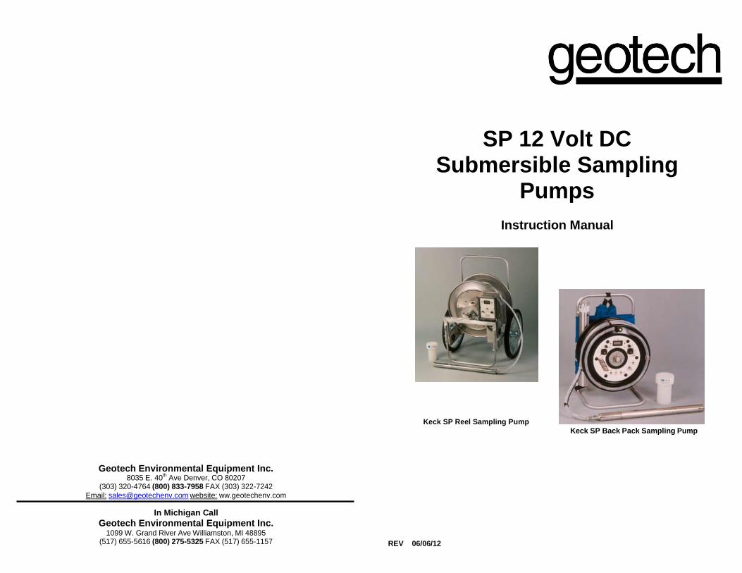
SP 12 Volt DC Submersible Sampling
Pumps
Instruction Manual
Keck SP Reel Sampling Pump
Keck SP Back Pack Sampling Pump
Geotech Environmental Equipment Inc. 8035 E. 40
th Ave Denver, CO 80207
(303) 320-4764 (800) 833-7958 FAX (303) 322-7242
Email: [email protected] website: ww.geotechenv.com
In Michigan Call
Geotech Environmental Equipment Inc. 1099 W. Grand River Ave Williamston, MI 48895
(517) 655-5616 (800) 275-5325 FAX (517) 655-1157
REV 06/06/12

2 31
Table of Contents
Chapter 1: System Description ............................................................. 3
Function and Theory ................................................................................ 3 Model SPP (Formerly SP-81) ..................................................................... 4 Model SPR (Formerly SP-84) ..................................................................... 5 Model SPB (Formerly SP-87) ..................................................................... 6
Construction ............................................................................................ 6 Initial operation ...................................................................................... 14 Operation................................................................................................ 16 Cleaning and Maintenance ................................................................... 22 The Warranty.......................................................................................... 28
30 3
Chapter 1: System Description
Function and Theory
Keck SP series Sampling Pumps have been constructed to provide reliable and efficient ground water samples from a 2” monitoring well. The pumps have a variable flow rate for continuous purging or sampling without agitation. The pumps come in three models for maximum site adaptability and are capable of operating at remote sites with a 12 VDC battery or directly from any 12 VDC vehicle capable of sustaining 13 to 14 volts and 15 amps. For maximum efficiency and performance for extended pumping periods, the battery pack or auto/battery monitor can be connected directly to a 12 VDC vehicle. The Keck SP can be connected to most high amp-hour marine batteries for sampling monitor wells that are not accessible with a field vehicle.

4 29
Model SPP (formerly SP-81) The SPP was designed to provide a sampling system capable of operating at remote sites.
Features
Pump with EPDM stator
Pump control monitor
Variable flow to 100 ml/minute
125 feet power cable (polyethylene jacket)
125 feet polyethylene discharge tubing Universal well sheave Accessories
Aluminum cable storage reel with slip ring
Inflatable packer, 2-inch
Inflatable packer, 4-inch
FE P hose
28 5
The Warranty
For a period of one (1) year from date of first sale, product is warranted to be free from defects in materials and workmanship. Geotech agrees to repair or replace, at Geotech’s option, the portion proving defective, or at our option to refund the purchase price thereof. Geotech will have no warranty obligation if the product is subjected to abnormal operating conditions, accident, abuse, misuse, unauthorized modification, alteration, repair, or replacement of wear parts. User assumes all other risk, if any, including the risk of injury, loss, or damage, direct or consequential, arising out of the use, misuse, or inability to use this product. User agrees to use, maintain and install product in accordance with recommendations and instructions. User is responsible for transportation charges connected to the repair or replacement of product under this warranty.
Equipment Return Policy
A Return Material Authorization number (RMA #) is required prior to return of any equipment to our facilities, please call our 800 number for appropriate location. An RMA# will be issued upon receipt of your request to return equipment, which should include reasons for the return. Your return shipment to us must have this RMA # clearly marked on the outside of the package. Proof of date of purchase is required for processing of all warranty requests.
This policy applies to both equipment sales and repair orders.
FOR A RETURN MATERIAL AUTHORIZATION, PLEASE CALL OUR SERVICE DEPARTMENT AT 1-800-833-7958 OR 1-800-275-5325.
Model Number:
Serial Number:
Date:
Equipment Decontamination
Prior to return, all equipment must be thoroughly cleaned and decontaminated. Please make note on RMA form, the use of equipment, contaminants equipment was exposed to, and decontamination solutions/methods used.
Geotech reserves the right to refuse any equipment not properly decontaminated. Geotech may also choose to decontaminate equipment for a fee, which will be applied to the repair order invoice.
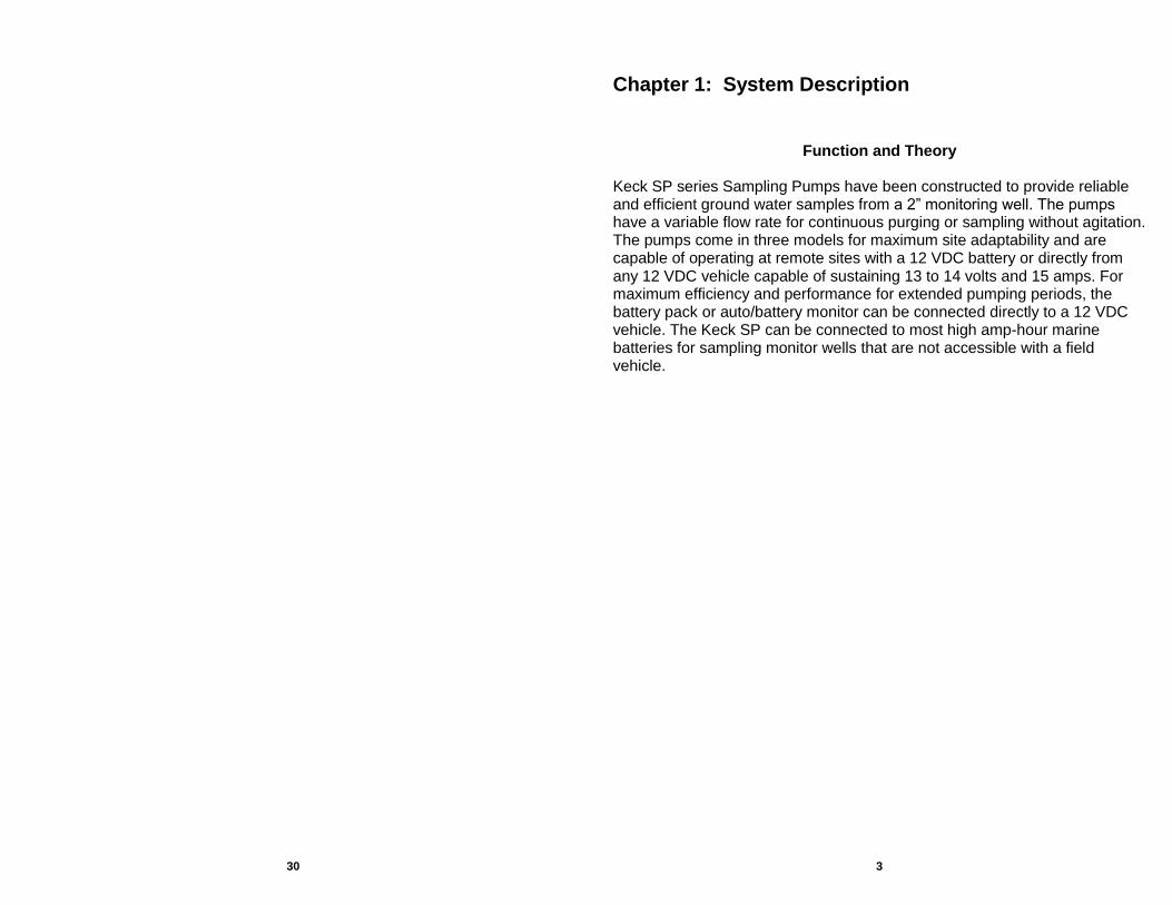
Model SPR (Formerly SP-84) The reel mounted SPR is equipped with 150 feet of power cable and discharge tubing on a storage reel with the auto/battery monitor enclosed in a watertight case. Features
Pump with EPDM stator
Cable reel with slip ring and pin-lock
Wheel kit
Pump monitor/control
Variable flow down to 100 ml/minute
150 feet power cable (polyethylene jacket)
150 feet polyethylene discharge tubing
Universal well sheave Accessories
Inflatable packer, 2-inch
Inflatable packer, 4-inch
FE P hose

6 27
Model SPB (Formerly SP-87) The SPB backpack system is light weight and features an internal power supply with variable flow for continuous purging or sampling without agitation. The system includes 60 feet of power cable and discharge hose with pump controls mounted directly in the cable reel.
Features
Backpack frame with reel
Variable flow down to 100 ml/minute
60 feet power cable (polyethylene jacket)
60 feet polyethylene discharge tubing
Universal well sheave Accessories
FE P hose
Construction

26 7
Each of the three modules is designed to detach from the adjacent module by removing three to eight external screws. This design allows for easier decontamination and field repair of the pump.
1. Electrical/Fluid Terminal Cap Module
The electrical/fluid terminal cap contains the terminations for the power cable and discharge tubing. The power cable has a strain relief attached inside of the cap and a tapered PTFE insert that is compressed with the ferrule fitting on the top of this module. The discharge tubing attaches to the 304 stainless steel hose barb on the top and the fluid path is completed through a transfer tube with O-rings on each end inside of the module. Both the positive and negative leads are soldered to the two ends of the 10- gauge power cable. The positive electrical boot slips on the pin connector attached to the top of the stator cap, and the negative lead is attached to the top of the stator cap with a grounding screw.
2. Pump Head Module
Pump housing, flexible shaft, rotor, stator, and stator cap. The pump head module consists of the intake area with inspection plate, flexible shaft, rotor, stator and stator cap. The flexible shaft is designed for both forward and reverse operation and is constructed of 304 stainless steel. The rotor, or helical screw, is machined from 316 stainless steel. The stator is constructed of 304 stainless tubing lined with a EPDM elastomeric compound. The stator cap attaches to the stator through the outer stainless steel shell and contains the positive 12 VDC electrical wire with male and female glass insulated connectors.
3. Motor Module
Motor housing, bottom cap, 12VDC motor, female hex drive and shaft seal. The motor module contains a 12 VDC gear motor specially designed for the Keck SP-Series pump. The highly efficient monobloc design allows continuous operation for mini-aquifer tests and evacuation of greater volumes of ground water.
Elastomeric Stators

25 8
Reaction to certain chemicals will cause a swelling of the stator and
subsequent increased friction or difficulty of operation which will cause the
pump to operate at a higher current level, or not at all. A decrease in volume
may indicate a worn stator which needs replacement.
EPDM
0
0
1----{11')
24 9
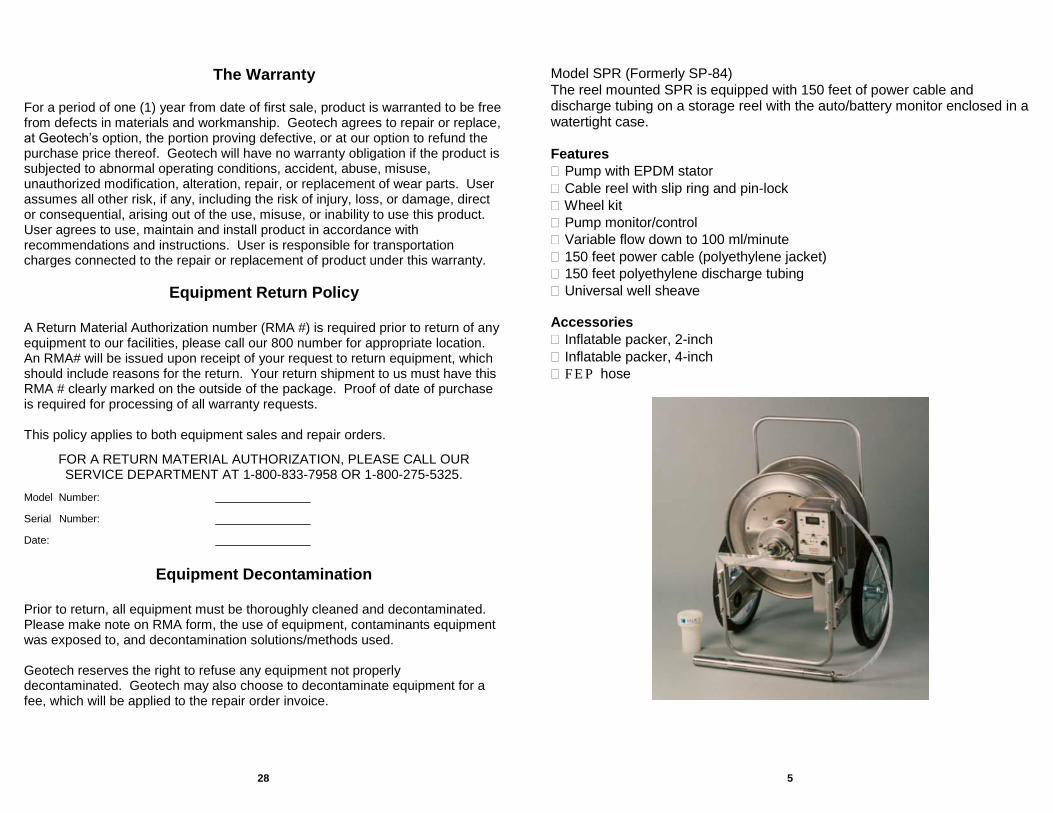
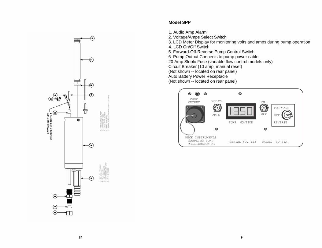
Model SPP
1. Audio Amp Alarm 2. Voltage/Amps Select Switch 3. LCD Meter Display for monitoring volts and amps during pump operation 4. LCD On/Off Switch 5. Forward-Off-Reverse Pump Control Switch 6. Pump Output Connects to pump power cable 20 Amp Sloblo Fuse (variable flow control models only) Circuit Breaker (10 amp, manual reset) (Not shown -- located on rear panel) Auto Battery Power Receptacle (Not shown -- located on rear panel)

10 23
MODEL SPR
1. Voltage/Amps Select Switch 2. LCD Meter Display for monitoring volts and amps during pump operation 3. LCD On/Off Switch 4. Reverse-Off-Forward Pump Control Switch
5. 20 Amp Sloblo Fuse (variable flow control models only)
5. Dispose of all wash and rinse water in a properly marked and sealed container for future disposal.
6. Inspect and re-tighten all 4-40 pump screws at the end of each day of operation.
Tools and Materials Required for Cleaning and Maintenance
6. Audio Amp Alarm 1. Open-end wrenches: 9/16", 5/8", and 11/16" 7. Audio Warning Signal Adjustment 2. Allen wrenches: 1/8", and 1/4"
3. Screw driver
4. Roll Pin Punches: 1/8" and 3/16"
5. Soldering iron
6. Multimeter
7. Heat shrink tubing
8. Solder
9. 4-40 F.H. screws x 1/4" and 3/8" lg.
10. 18 Awg wire
Do not re-use screws

22 11
Cleaning and Maintenance A thorough decontamination of the pump will increase the operating efficiency of the system. The various techniques used to clean sampling equipment generally depend on the critical nature of the type of sampling required for each project. An effective method for cleaning the pump head and transfer tubing is to pump cleaning solution through the pump and reverse the pump to evacuate the tubing and flush the intake area. Any procedure that uses a cleaning or chemical solution must be followed by pumping clean water through the system.
The pump current should be monitored during the cleaning process to detect any change in the operating condition. An increase in current may indicate that either the cleaning agent reacted with the elastomer, causing it to swell, or a residual film of the cleaning agent was not removed with the clean water rinse. Conversely, a decrease in the current would indicate that foreign material or contamination has been removed during the cleaning process.
Geotech recommends the following procedure for the SP-Series submersible sampling pump:
1. Wash sampling equipment in a container with a solution of good quality
lab soap, such as micro soap or Liquinox. Completely brush the entire exterior surface of the article. Wash interior wetted surfaces as required.
2. Rinse sampling equipment, except that used for samples intended for volatiles in a container of a 10 percent solution of acetone and water. Completely brush the entire exterior surface of the article. Rinse interior wetted surfaces as required. If PCBs or pesticides are suspected to be present, the final rinse should be carried out with a hexane solution. Equipment used for samples intended for volatile organic analysis should not have a solvent rinse. Technical or reagent grade solvents should be used.
3. Rinse sampling equipment in a container of clean water. Completely brush the entire exterior surface of the article. Rinse interior wetted surfaces as required.
4. Rinse sampling equipment by pouring or spraying clean water over the equipment surfaces. Lay equipment on clean plastic to air dry as much as possible before reuse.
MODEL SPB 1. LCD Meter Display for monitoring volts and amps during pump operation
and charging
2. LCD On/Off Switch
3. External 12VDC Fuse (20 Amp)
4. External 12VDC Input
5. Battery Power Select Switch
6. Variable Flow Adjustment
7. Flow Rate Select Switch
8. Output Circuit Breaker
9. Forward-Off-Reverse Pump Control Switch
10. 12VDC Charging Input
11. Charging Circuit Fuse (4 Amp)
12. Voltage/Amps Select Switch
12 21
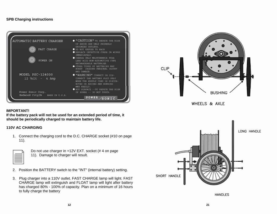
SPB Charging instructions
IMPORTANT! If the battery pack will not be used for an extended period of time, it should be periodically charged to maintain battery life.
110V AC CHARGING
1. Connect the charging cord to the D.C. CHARGE socket (#10 on page
11).
Do not use charger in +12V EXT. socket (# 4 on page 11). Damage to charger will result.
2. Position the BATTERY switch to the "INT" (internal battery) setting.
3. Plug charger into a 110V outlet. FAST CHARGE lamp will light. FAST CHARGE lamp will extinguish and FLOAT lamp will light after battery has charged 80% - 100% of capacity. Plan on a minimum of 16 hours to fully charge the battery

20 13
IMPORTANT!
Step 12 Connect the female electrical boot from the bottom of the Inflatable Packer Module to the glass insulated electrical terminal on top of the pump by pushing the boot over the pin.
Step 13 Lubricate the lower end of the fluid transfer tube and the upper end
of the pump with water to prevent damage to the o-rings. Step 14 Orient the Inflatable Packer Module so that the transfer tube will be
in alignment with the hole located on the top of the pump. Step 15 Push the lower end of the Inflatable Packer Module onto the top of
the pump. Step 16 Replace the three screws to secure the module to the pump.
Step 17 Connect the 1/8 inch air line to the air fitting at the top of the pump
by simply inserting the tube.
To remove the air line, push the collect in and pull on the tubing.
DC CHARGING
1. Connect the 12VDC jumpers to the D.C. CHARGE socket (# 10 on page 11). Connect the jumpers to the 12VDC power supply positive (+) terminal [red] and to the negative (-) terminal [black].
2. Position the BATTERY switch to the "INT" (internal battery) setting.
3. Check the current level with the amp meter. When current drops
below 0.30 amps, battery is 80% - 100% charged.
Battery must be fully charged after field use.
The Inflatable Packer Module was NOT designed to support the extended weight of the pump. When installing or removing the system, support the unit by holding the solid pump body. Always store the complete assembly in a container that will provide full support of the system and prevent any lateral force from bending or damaging the module.
Use air line plug when air line is not in fitting. Inspect and re-tighten all 4-40 pump screws at the end of each day of operation.

14 19
Step 1 Remove the discharge tubing from the hose barb at the top of the pump.
Hose must be off! Most pumps won't start "dry."
Step 2 Submerge the pump in clean, cool water (55°F) so that the unit is vertical and the water level is above the hose barb. Allow to set for at least five minutes for temperature equalization.
The pump should not be operated "DRY" at any time. Operation of the unit without water to lubricate the moving parts will cause damage and eventual malfunction of the pump.
Step 3 Connect the power cable to the 12 VDC power supply; 13 to 14 VDC is required for the initial starting of the pump. Positive (+) terminal [red] and negative (-) terminal [black].
Note: Do not reverse positive and negative terminal or monitor damage may occur.
Water must be cool: warm water swells stator
Step 4 Turn the Voltage/Current Meter to “ON - VOLTAGE”. If 13 to 14 volts are displayed, proceed to the next step.
A constant 13 to 14VDC are required to operate the unit at a stable current level. Operation of the pump with less than 12 volts will cause excessive brush and commutator wear and the subsequent premature failure of the motor. No LCD display -- check fuses and connections. Was the battery tested under load? Running vehicle may help.
Step 5 Turn the Voltage/Current Meter to “AMPS”.
No change in display is no load; check continuity.
Step 6 Turn the Pump Control Switch to “FORWARD”, observing the current level at the same time. STOP immediately if the current exceeds 10.0 amps or the meter "blanks out," which is greater than 20.0 amps
Initial operation Follow Procedure column (shaded) for operation. Consult Troubleshooting column for common problems at each step.
Procedure Troubleshooting
INSTRUCTIONS FOR ATTACHING 2" INFLATABLE PACKER The SP Inflatable Packer is designed to attach to the upper portion of the basic sampling pump. To install the packer, follow these simplified steps: Step 1 Remove the three screws that secure the Electrical/Fluid Terminal
Cap. Step 2 Pull the Electrical/Fluid Terminal Cap away from the remainder of
the pump without rotating. IMPORTANT! Care should be exercised to prevent damage to the glass-insulated electrical terminal on the top of the pump. Step 3 Remove the screw that secures the ground or negative wire lead. Step 4 Disconnect the female electrical boot from the glass-insulated
electrical terminal by pulling the boot straight up. Step 5 Remove the fluid transfer tube. Step 6 Connect the female electrical boot from Electrical/Fluid Terminal
Cap to the glass insulated electrical terminal on the Inflatable Packer Module by pushing the boot over the pin.
Step 7 Attach the ground or negative wire lead with the screw. Step 8 Push the 1/8 inch air line onto the hose barb on the top of the
Inflatable Packer Module. Step 9 Lubricate the transfer tube with water to prevent damage to the o-
rings and push securely into the hole located within the upper portion of the Electrical/Fluid Terminal Cap, taking care not to pinch the electric wire or air line.
Step 10 Push the Electrical/Fluid Terminal Cap onto the upper end of the
Inflatable Packer Module. Step 11 Replace the three screws to secure the module to the
Electrical/Fluid Terminal Cap.

18 15
Step 7 Less than 10.0 amps: Continue to operate the pump until the current stabilizes between 4 and 7 amps.
Fluctuates and will not stabilize: needs repair.
Step 8 Greater than 10.0 amps: Check to see that the top of the pump is submerged and be prepared to “rock” the Pump Control Switch from “REVERSE” to “FORWARD”. Repeat if necessary, to rotate the pumping mechanism until the pump head is lubricated with water and the current stabilizes between 4 and 7 amps.
High or increased current: contaminated or swollen from solvents; decontaminate with proper cleaning agent and distilled water. Amp meter “blanks out”: decontaminate with proper cleaning agent and distilled water. Sand-locked; clean by washing through hose barb.
Step 9 Connect the discharge tubing. Step 10 Turn the Pump Control Switch
to “FORWARD”, observe the current level, and operate the pump until the current stabilizes between 4 and 7 amps.
If more than 2 to 3 amps higher than with hose off: kink in line, collapsed liner, clogged with sand or silt, or frozen: test without tubing connected and correct.
Step 11 Turn the Pump Control Switch to “REVERSE”, observing the current level, to evacuate the tubing of the water while leaving the pump submerged in water.
If pump will not operate in reverse it needs repair.
Step12 Disconnect the discharge tubing.
Stop 13 Turn the Pump Control Switch to “FORWARD” for about five seconds, or until the current stabilizes between 4 and 7 amps.
Step 14 The sampling pump is ready for field operation.
Inflatable Packer
Technical personnel actively engaged in ground water monitoring have recently become more aware of the importance of evacuating the borehole volume to obtain a representative sample. The standard procedure presently used requires that three to five times the volume of water within the well should be evacuated prior to collecting the groundwater sample to be sent to the laboratory for chemical analysis. The use of some more recently developed sampling pumps has reduced the time required to evacuate and sample each monitor well: however, the time required varies due to the different heights of the column of water within each well. In addition, many projects require that the evacuated water be collected and disposed at a treatment facility. Both of these factors increase the cost of monitoring and sampling. The use of an inflatable packer can
Procedure Troubleshooting
reduce the time, cost and effort when sampling monitoring wells. The packer is mounted immediately above the top of the screen with the pump placed within the screen. This allows the pump to evacuate or draw water from only the screened portion of the well. Assuming that an average monitoring well has at least 5 feet of screen, the time to sample each well would be the same with a minimal amount of effort and effluent collected. The actual pumping time to evacuate the screened portion (5 feet) three to five times would be less than five minutes for a 2 inch well and about 16 minutes for a 4 inch well. This allows the pump to evacuate or draw water from only the screened portion of the well.
16 17
Operation
Check NEW wells for plumbness and diameter, using a bailer of the same dimensions as the Keck pump (1.75” OD x 25” long). Use a water level sensing device to determine the water level to insure that the pump is totally submerged when sampling.
IMPORTANT!
The pump should not be operated “DRY” at any time. Operation of the unit without water to lubricate the moving parts will cause damage and eventual malfunction of the pump.
When lowering the pump into the well, allow the weight of the unit to keep the power cord taut. The pump can and will cock inside a 4 inch well and may become lodged.
IMPORTANT!
A constant 13 to 14 VDC are required to operate the unit at a stale current level. Operation of the pump with less than 12 volts will cause excessive brush and commutator wear and the subsequent premature failure of the motor.
Operation of the pump for extended periods requires a continuous 13 to 14 VDC power source rated for 15 amps. Amperage must be monitored while the pump is operating. A sudden increase in the amps indirectly informs the operator that conditions have changed, e.g., an increase in the percent of solids in the flow stream, to rotor and stator are partially sand-locked, the discharge tubing is blocked, frozen or kinked, or the voltage to the pump motor is inadequate because of cuts in the power cable, poor electrical connections, or an inadequate power supply. Continuing to operate the pup in this condition may cause a malfunction of the pump as a result of inadequate power reaching the 12 VDC motor.
The Pump Control Switch, “FORWARD-OFF-REVERSE”, not only turns the pump ON, but allows the operator to reverse the pump rotation if the unit should become clogged, or to evacuate the discharge tubing. NOTE: ALWAYS operate the pump in the “FORWARD” position after reverse has been engaged to reposition the “floating” rotor within the stator.
IMPORTANT!
It is important to decontaminate the pump after sampling and to drain the transfer tubing prior to extended storage. (See Cleaning and Maintenance section).
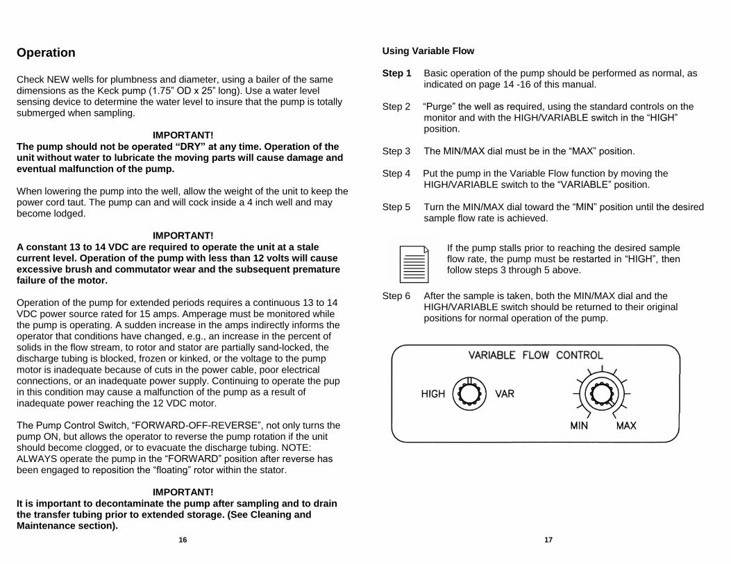
Using Variable Flow Step 1 Basic operation of the pump should be performed as normal, as
indicated on page 14 -16 of this manual. Step 2 “Purge” the well as required, using the standard controls on the
monitor and with the HIGH/VARIABLE switch in the “HIGH” position.
Step 3 The MIN/MAX dial must be in the “MAX” position. Step 4 Put the pump in the Variable Flow function by moving the
HIGH/VARIABLE switch to the “VARIABLE” position. Step 5 Turn the MIN/MAX dial toward the “MIN” position until the desired
sample flow rate is achieved.
If the pump stalls prior to reaching the desired sample flow rate, the pump must be restarted in “HIGH”, then follow steps 3 through 5 above.
Step 6 After the sample is taken, both the MIN/MAX dial and the
HIGH/VARIABLE switch should be returned to their original positions for normal operation of the pump.