
Keccak sponge function family main document
100
Keccak sponge function family main document Guido Bertoni 1 Joan Daemen 1 Micha el Peeters 2 Gilles Van Assche 1 http://keccak.noekeon.org/ Version 2.0 September 10, 2009 1 STMicroelectronics 2 NXP Semiconductors
Transcript of Keccak sponge function family main document
Keccak sponge function family
main document
Guido Bertoni1
Joan Daemen1
Michael Peeters2
Gilles Van Assche1
http://keccak.noekeon.org/
Version 2.0September 10, 2009
1STMicroelectronics2NXP Semiconductors

Keccak
2 / 100
Contents
1 Introduction 7
1.1 Specifications summary . . . . . . . . . . . . . . . . . . . . . . . . . . . . . . 8
1.2 NIST requirements . . . . . . . . . . . . . . . . . . . . . . . . . . . . . . . . . 11
1.3 Acknowledgments . . . . . . . . . . . . . . . . . . . . . . . . . . . . . . . . . . 12
2 Design rationale summary 13
2.1 Choosing the sponge construction . . . . . . . . . . . . . . . . . . . . . . . . . 13
2.2 Choosing an iterated permutation . . . . . . . . . . . . . . . . . . . . . . . . 14
2.3 Designing the Keccak-f permutations . . . . . . . . . . . . . . . . . . . . . 14
2.4 Choosing the parameter values . . . . . . . . . . . . . . . . . . . . . . . . . . 15
2.5 The difference between version 1 and version 2 of Keccak . . . . . . . . . . 16
3 The sponge construction 17
3.1 Security of the sponge construction . . . . . . . . . . . . . . . . . . . . . . . . 17
3.1.1 Indifferentiability from a random oracle . . . . . . . . . . . . . . . . . 17
3.1.2 Indifferentiability of multiple sponge functions . . . . . . . . . . . . . 18
3.1.3 Immunity to generic attacks . . . . . . . . . . . . . . . . . . . . . . . . 19
3.1.4 Randomized hashing . . . . . . . . . . . . . . . . . . . . . . . . . . . . 19
3.1.5 Keyed modes . . . . . . . . . . . . . . . . . . . . . . . . . . . . . . . . 20
3.2 Rationale for the padding . . . . . . . . . . . . . . . . . . . . . . . . . . . . . 20
3.2.1 Sponge input preparation . . . . . . . . . . . . . . . . . . . . . . . . . 20
3.2.2 Multi-capacity property . . . . . . . . . . . . . . . . . . . . . . . . . . 21
3.2.3 Digest-length dependent digest . . . . . . . . . . . . . . . . . . . . . . 21
3.3 Parameter choices . . . . . . . . . . . . . . . . . . . . . . . . . . . . . . . . . 21
3.3.1 Capacity . . . . . . . . . . . . . . . . . . . . . . . . . . . . . . . . . . 21
3.3.2 Width . . . . . . . . . . . . . . . . . . . . . . . . . . . . . . . . . . . . 22
3.3.3 The default sponge function Keccak[] . . . . . . . . . . . . . . . . . . 22
3.4 The four critical operations of a sponge . . . . . . . . . . . . . . . . . . . . . 23
3.4.1 Definitions . . . . . . . . . . . . . . . . . . . . . . . . . . . . . . . . . 23
3.4.2 The operations . . . . . . . . . . . . . . . . . . . . . . . . . . . . . . . 23
4 Sponge functions with an iterated permutation 25
4.1 The philosophy . . . . . . . . . . . . . . . . . . . . . . . . . . . . . . . . . . . 25
4.1.1 The hermetic sponge strategy . . . . . . . . . . . . . . . . . . . . . . . 25
4.1.2 The impossibility of implementing a random oracle . . . . . . . . . . . 25
4.1.3 The choice between a permutation and a transformation . . . . . . . . 26
3 / 100
Keccak CONTENTS
4.1.4 The choice of an iterated permutation . . . . . . . . . . . . . . . . . . 264.2 Some structural distinguishers . . . . . . . . . . . . . . . . . . . . . . . . . . . 27
4.2.1 Differential cryptanalysis . . . . . . . . . . . . . . . . . . . . . . . . . 274.2.2 Linear cryptanalysis . . . . . . . . . . . . . . . . . . . . . . . . . . . . 284.2.3 Algebraic expressions . . . . . . . . . . . . . . . . . . . . . . . . . . . 294.2.4 The constrained-input constrained-output (CICO) problem . . . . . . 304.2.5 Multi-block CICO problems . . . . . . . . . . . . . . . . . . . . . . . . 314.2.6 Cycle structure . . . . . . . . . . . . . . . . . . . . . . . . . . . . . . . 32
4.3 Inner collision . . . . . . . . . . . . . . . . . . . . . . . . . . . . . . . . . . . . 324.3.1 Exploiting a differential trail . . . . . . . . . . . . . . . . . . . . . . . 324.3.2 Exploiting a differential . . . . . . . . . . . . . . . . . . . . . . . . . . 334.3.3 Truncated trails and differentials . . . . . . . . . . . . . . . . . . . . . 34
4.4 Path to an inner state . . . . . . . . . . . . . . . . . . . . . . . . . . . . . . . 344.5 Detecting a cycle . . . . . . . . . . . . . . . . . . . . . . . . . . . . . . . . . . 344.6 Binding an output to a state . . . . . . . . . . . . . . . . . . . . . . . . . . . 344.7 Classical hash function criteria . . . . . . . . . . . . . . . . . . . . . . . . . . 35
4.7.1 Collision resistance . . . . . . . . . . . . . . . . . . . . . . . . . . . . . 354.7.2 Preimage resistance . . . . . . . . . . . . . . . . . . . . . . . . . . . . 354.7.3 Second preimage resistance . . . . . . . . . . . . . . . . . . . . . . . . 354.7.4 Length extension . . . . . . . . . . . . . . . . . . . . . . . . . . . . . . 364.7.5 Pseudo-random function . . . . . . . . . . . . . . . . . . . . . . . . . . 364.7.6 Output subset properties . . . . . . . . . . . . . . . . . . . . . . . . . 36
5 The Keccak-f permutations 375.1 Translation invariance . . . . . . . . . . . . . . . . . . . . . . . . . . . . . . . 375.2 The Matryoshka structure . . . . . . . . . . . . . . . . . . . . . . . . . . . . . 385.3 The step mappings of Keccak-f . . . . . . . . . . . . . . . . . . . . . . . . . 38
5.3.1 Properties of � . . . . . . . . . . . . . . . . . . . . . . . . . . . . . . . 395.3.2 Properties of � . . . . . . . . . . . . . . . . . . . . . . . . . . . . . . . 415.3.3 Properties of � . . . . . . . . . . . . . . . . . . . . . . . . . . . . . . . 435.3.4 Properties of � . . . . . . . . . . . . . . . . . . . . . . . . . . . . . . . 445.3.5 Properties of � . . . . . . . . . . . . . . . . . . . . . . . . . . . . . . . 455.3.6 The order of steps within a round . . . . . . . . . . . . . . . . . . . . 46
5.4 Choice of parameters: the number of rounds . . . . . . . . . . . . . . . . . . . 465.5 Differential and linear cryptanalysis . . . . . . . . . . . . . . . . . . . . . . . 46
5.5.1 Trail propagation . . . . . . . . . . . . . . . . . . . . . . . . . . . . . . 465.5.2 The Matryoshka consequence . . . . . . . . . . . . . . . . . . . . . . . 475.5.3 The column parity kernel . . . . . . . . . . . . . . . . . . . . . . . . . 475.5.4 One and two-round trails . . . . . . . . . . . . . . . . . . . . . . . . . 485.5.5 Three-round trails: kernel vortices . . . . . . . . . . . . . . . . . . . . 485.5.6 Beyond three-round trails: choice of � . . . . . . . . . . . . . . . . . . 505.5.7 Truncated trails and differentials . . . . . . . . . . . . . . . . . . . . . 515.5.8 Other group operations . . . . . . . . . . . . . . . . . . . . . . . . . . 525.5.9 Differential and linear cryptanalysis variants . . . . . . . . . . . . . . 525.5.10 Bounds for symmetric trails . . . . . . . . . . . . . . . . . . . . . . . . 53
5.6 Solving CICO problems . . . . . . . . . . . . . . . . . . . . . . . . . . . . . . 535.7 Distinguishers exploiting low algebraic degree . . . . . . . . . . . . . . . . . . 54
4 / 100
CONTENTS Keccak
5.8 Strength in keyed mode . . . . . . . . . . . . . . . . . . . . . . . . . . . . . . 555.9 Symmetry weaknesses . . . . . . . . . . . . . . . . . . . . . . . . . . . . . . . 555.10 Experimental data . . . . . . . . . . . . . . . . . . . . . . . . . . . . . . . . . 55
5.10.1 Differential probability distributions . . . . . . . . . . . . . . . . . . . 565.10.2 Correlation distributions . . . . . . . . . . . . . . . . . . . . . . . . . . 575.10.3 Algebraic normal form experiments . . . . . . . . . . . . . . . . . . . . 615.10.4 Solving CICO problems algebraically . . . . . . . . . . . . . . . . . . . 635.10.5 Cycle distributions . . . . . . . . . . . . . . . . . . . . . . . . . . . . . 65
5.11 Tame trails . . . . . . . . . . . . . . . . . . . . . . . . . . . . . . . . . . . . . 66
6 Usage 696.1 Usage scenario’s for a sponge function . . . . . . . . . . . . . . . . . . . . . . 69
6.1.1 Random-oracle interface . . . . . . . . . . . . . . . . . . . . . . . . . . 696.1.2 Linking to the security claim . . . . . . . . . . . . . . . . . . . . . . . 696.1.3 Examples of modes of use . . . . . . . . . . . . . . . . . . . . . . . . . 70
6.2 Backward compatibility with old standards . . . . . . . . . . . . . . . . . . . 716.2.1 Input block length and output length . . . . . . . . . . . . . . . . . . 716.2.2 Initial value . . . . . . . . . . . . . . . . . . . . . . . . . . . . . . . . . 716.2.3 HMAC . . . . . . . . . . . . . . . . . . . . . . . . . . . . . . . . . . . 716.2.4 NIST and other relevant standards . . . . . . . . . . . . . . . . . . . . 71
6.3 Input formatting and diversification . . . . . . . . . . . . . . . . . . . . . . . 726.4 Parallel and tree hashing . . . . . . . . . . . . . . . . . . . . . . . . . . . . . . 73
6.4.1 Definitions . . . . . . . . . . . . . . . . . . . . . . . . . . . . . . . . . 736.4.2 Soundness . . . . . . . . . . . . . . . . . . . . . . . . . . . . . . . . . . 756.4.3 Discussion . . . . . . . . . . . . . . . . . . . . . . . . . . . . . . . . . . 75
7 Implementation 777.1 Bit and byte numbering conventions . . . . . . . . . . . . . . . . . . . . . . . 777.2 General aspects . . . . . . . . . . . . . . . . . . . . . . . . . . . . . . . . . . . 78
7.2.1 The lane complementing transform . . . . . . . . . . . . . . . . . . . . 797.2.2 Bit interleaving . . . . . . . . . . . . . . . . . . . . . . . . . . . . . . . 80
7.3 Software implementation . . . . . . . . . . . . . . . . . . . . . . . . . . . . . . 817.3.1 Optimized for speed . . . . . . . . . . . . . . . . . . . . . . . . . . . . 827.3.2 Using SIMD instructions . . . . . . . . . . . . . . . . . . . . . . . . . . 837.3.3 SIMD instructions and KeccakTree . . . . . . . . . . . . . . . . . . 847.3.4 Protection against side channel attacks . . . . . . . . . . . . . . . . . 857.3.5 Estimation on 8-bit processors . . . . . . . . . . . . . . . . . . . . . . 85
7.4 Hardware implementation . . . . . . . . . . . . . . . . . . . . . . . . . . . . . 867.4.1 High-speed core . . . . . . . . . . . . . . . . . . . . . . . . . . . . . . . 877.4.2 Variants of the high-speed core . . . . . . . . . . . . . . . . . . . . . . 887.4.3 Low-area coprocessor . . . . . . . . . . . . . . . . . . . . . . . . . . . . 897.4.4 Protection against side channel attacks . . . . . . . . . . . . . . . . . 91
A Change log 99A.1 From 1.2 to 2.0 . . . . . . . . . . . . . . . . . . . . . . . . . . . . . . . . . . . 99A.2 From 1.1 to 1.2 . . . . . . . . . . . . . . . . . . . . . . . . . . . . . . . . . . . 100A.3 From 1.0 to 1.1 . . . . . . . . . . . . . . . . . . . . . . . . . . . . . . . . . . . 100
5 / 100

Keccak CONTENTS
6 / 100
Chapter 1
Introduction
Keccak [11] is a family of cryptographic hash functions [75] or, more accurately, spongefunctions [9]. This document describes the properties of the Keccak family and presentsits members as candidates to NIST’s request for a new cryptographic hash algorithm familycalled SHA-3 [57].
This introduction offers in Section 1.1 a summary of the Keccak specifications usingpseudocode, sufficient to understand its structure and building blocks. In no way should thisintroductory text be considered as a formal and reference description of Keccak. For theformal definition of the Keccak family, we refer to the separate document [11], to which weassume the reader has access. While the Keccak definition is updated once (for the SHA-32nd round), this present document is regularly updated, so we suggest the reader to obtainthe latest version from our website http://keccak.noekeon.org/.
The document is organized as follows. The design choices behind the Keccak spongefunctions are summarized in Chapter 2. Chapters 3–5 provide a security analysis and arationale for our design choices. Each of these three chapters looks at a particular level, fromtop to bottom.
∙ Chapter 3 looks at the use of the sponge construction in our submission.
∙ Chapter 4 gives more insight on the use of an iterated permutation in the spongeconstruction.
∙ Chapter 5 looks more particularly at Keccak-f , the chosen permutation.
Examples of modes of use, as well as other details regarding the use of the Keccak spongefunctions, are provided in Chapter 6. Finally, Chapter 7 takes a look at the software andhardware implementation aspects.
7 / 100
Keccak 1. Introduction
1.1 Specifications summary
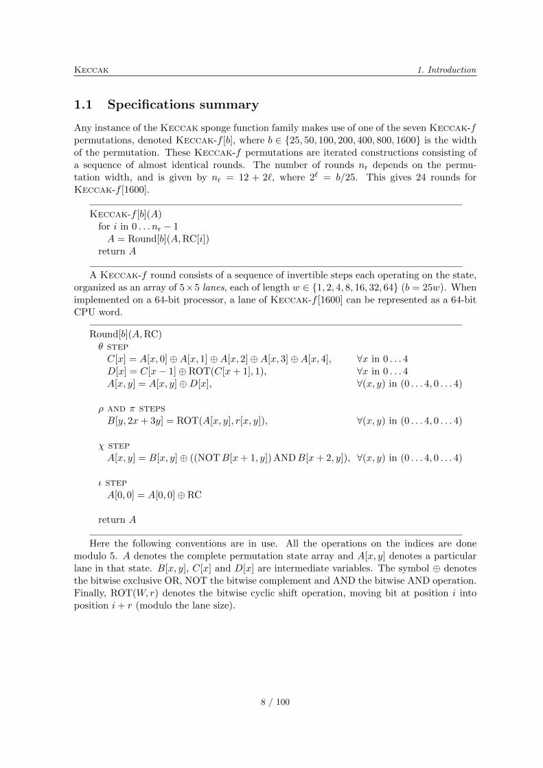
Any instance of the Keccak sponge function family makes use of one of the seven Keccak-fpermutations, denoted Keccak-f [b], where b ∈ {25, 50, 100, 200, 400, 800, 1600} is the widthof the permutation. These Keccak-f permutations are iterated constructions consisting ofa sequence of almost identical rounds. The number of rounds nr depends on the permu-tation width, and is given by nr = 12 + 2ℓ, where 2ℓ = b/25. This gives 24 rounds forKeccak-f [1600].
Keccak-f [b](A)for i in 0 . . . nr − 1A = Round[b](A,RC[i])
return A
A Keccak-f round consists of a sequence of invertible steps each operating on the state,organized as an array of 5×5 lanes, each of length w ∈ {1, 2, 4, 8, 16, 32, 64} (b = 25w). Whenimplemented on a 64-bit processor, a lane of Keccak-f [1600] can be represented as a 64-bitCPU word.
Round[b](A,RC)� stepC[x] = A[x, 0]⊕A[x, 1]⊕A[x, 2]⊕A[x, 3]⊕A[x, 4], ∀x in 0 . . . 4D[x] = C[x− 1]⊕ ROT(C[x+ 1], 1), ∀x in 0 . . . 4A[x, y] = A[x, y]⊕D[x], ∀(x, y) in (0 . . . 4, 0 . . . 4)
� and � stepsB[y, 2x+ 3y] = ROT(A[x, y], r[x, y]), ∀(x, y) in (0 . . . 4, 0 . . . 4)
� stepA[x, y] = B[x, y]⊕ ((NOTB[x+ 1, y]) ANDB[x+ 2, y]), ∀(x, y) in (0 . . . 4, 0 . . . 4)
� stepA[0, 0] = A[0, 0]⊕ RC
return A
Here the following conventions are in use. All the operations on the indices are donemodulo 5. A denotes the complete permutation state array and A[x, y] denotes a particularlane in that state. B[x, y], C[x] and D[x] are intermediate variables. The symbol ⊕ denotesthe bitwise exclusive OR, NOT the bitwise complement and AND the bitwise AND operation.Finally, ROT(W, r) denotes the bitwise cyclic shift operation, moving bit at position i intoposition i+ r (modulo the lane size).
8 / 100
1. Introduction Keccak
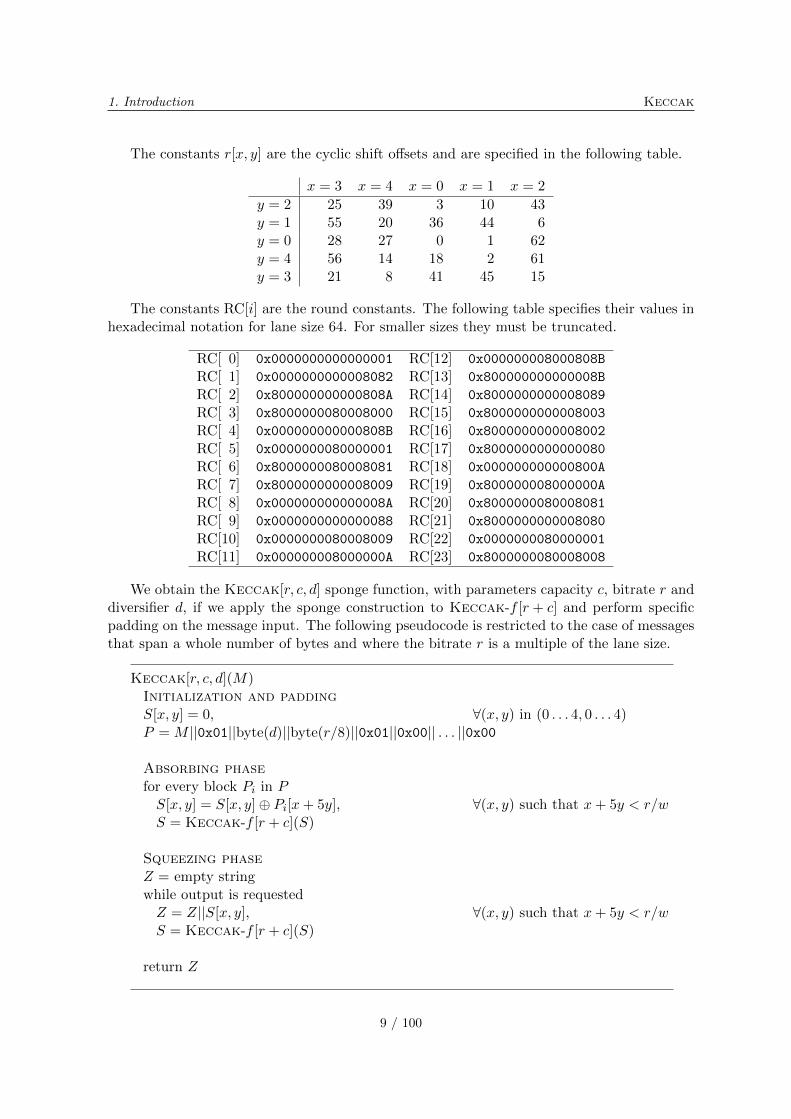
The constants r[x, y] are the cyclic shift offsets and are specified in the following table.
x = 3 x = 4 x = 0 x = 1 x = 2
y = 2 25 39 3 10 43y = 1 55 20 36 44 6y = 0 28 27 0 1 62y = 4 56 14 18 2 61y = 3 21 8 41 45 15
The constants RC[i] are the round constants. The following table specifies their values inhexadecimal notation for lane size 64. For smaller sizes they must be truncated.
RC[ 0] 0x0000000000000001 RC[12] 0x000000008000808B
RC[ 1] 0x0000000000008082 RC[13] 0x800000000000008B
RC[ 2] 0x800000000000808A RC[14] 0x8000000000008089
RC[ 3] 0x8000000080008000 RC[15] 0x8000000000008003
RC[ 4] 0x000000000000808B RC[16] 0x8000000000008002
RC[ 5] 0x0000000080000001 RC[17] 0x8000000000000080
RC[ 6] 0x8000000080008081 RC[18] 0x000000000000800A
RC[ 7] 0x8000000000008009 RC[19] 0x800000008000000A
RC[ 8] 0x000000000000008A RC[20] 0x8000000080008081
RC[ 9] 0x0000000000000088 RC[21] 0x8000000000008080
RC[10] 0x0000000080008009 RC[22] 0x0000000080000001
RC[11] 0x000000008000000A RC[23] 0x8000000080008008
We obtain the Keccak[r, c, d] sponge function, with parameters capacity c, bitrate r anddiversifier d, if we apply the sponge construction to Keccak-f [r + c] and perform specificpadding on the message input. The following pseudocode is restricted to the case of messagesthat span a whole number of bytes and where the bitrate r is a multiple of the lane size.
Keccak[r, c, d](M)Initialization and paddingS[x, y] = 0, ∀(x, y) in (0 . . . 4, 0 . . . 4)P = M ∣∣0x01∣∣byte(d)∣∣byte(r/8)∣∣0x01∣∣0x00∣∣ . . . ∣∣0x00
Absorbing phasefor every block Pi in PS[x, y] = S[x, y]⊕ Pi[x+ 5y], ∀(x, y) such that x+ 5y < r/wS = Keccak-f [r + c](S)
Squeezing phaseZ = empty stringwhile output is requestedZ = Z∣∣S[x, y], ∀(x, y) such that x+ 5y < r/wS = Keccak-f [r + c](S)
return Z
9 / 100

Keccak 1. Introduction
Here S denotes the state as an array of lanes. The padded message P is organised asan array of blocks Pi, themselves organized as arrays of lanes. The ∣∣ operator denotes bytestring concatenation.
10 / 100
1. Introduction Keccak
1.2 NIST requirements
In this section, we provide a mapping from the items required by NIST to the appropriatesections in this document.
∙ Requirements in [57, Section 2.B.1]
– The complete specifications can be found in [11].
– Design rationale: a summary is provided in Chapter 2, with pointers to sectionswith more details.
– Any security argument and a preliminary analysis: this is the purpose of thecomplete Chapters 3–5.
– Tunable parameters: a summary is provided in Section 2.4, with pointers to sec-tions with more details.
– Recommended value for each digest size: see [11, Section 1] for the number ofrounds and [11, Section 4] for the other parameters.
– Bounds below which we expect cryptanalysis to become practical: this can befound in Sections 3.3.2 and 5.4.
∙ Requirements in [57, Section 2.B.2]
– The estimated computational efficiency can be found in Chapter 7.
– A description of the platforms used to generate the estimates can be found inSection 7.3.1.
– The speed estimate on the reference platform can also be found in Section 7.3.1.
∙ Requirements in [57, Section 2.B.3]
– The known answer and Monte Carlo results can be found on the optical media.
∙ Requirements in [57, Section 2.B.4]
– The expected strength of Keccak is stated in [11, Section 3].
– The link between the security claim and the expected strength criteria listed in[57, Section 4.A] can be found in Section 6.1.2. More details can be found inSections 3.1.3, 3.1.4, 3.1.5 and 4.7.
– For HMAC specifically, see also Section 6.2.3.
– Other pseudo random functions (PRF) constructions: some modes of use are pro-posed in Section 6.1.
∙ Requirements in [57, Section 2.B.5]
– We formally state that we have not inserted any trapdoor or any hidden weaknessin Keccak. Moreover, we believe that the structure of the Keccak-f permutationdoes not offer enough degrees of freedom to hide a trapdoor or any other weakness.
∙ Requirements in [57, Section 2.B.6]
– Advantages and limitations: a summary is provided in Chapter 2, with pointersto sections with more details.
11 / 100
Keccak 1. Introduction
1.3 Acknowledgments
We wish to thank (in no particular order) Charles Bouillaguet and Pierre-Alain Fouque fordiscussing their results later published in [15] with us, Dmitry Khovratovich for discussingwith us the results published in [44] and for his analysis in [2], Jean-Philippe Aumasson forhis analysis in [2] and [3], Joel Lathrop for his analysis in [52] and Willi Meier for his analysisin [3], Joachim Strombergson for useful comments on the FPGA implementation, Joppe Bosfor reporting a bug in the optimized implementation, Yves Moulart, Bernard Kasser andall our colleagues at STMicroelectronics and NXP Semiconductors for creating the workingenvironment in which we could work on this, and especially Joris Delclef and Jean-LouisModave for kindly lending us fast hardware.
12 / 100
Chapter 2
Design rationale summary
The purpose of this chapter is to list the design choices and to briefly motivate them, althoughfurther analysis is provided in the subsequent chapters.
2.1 Choosing the sponge construction
We start with defining a generic attack:
Definition 1. A shortcut attack [11] on a sponge function is a generic attack if it does notexploit specific properties of the underlying permutation or transformation.
The Keccak hash function makes use of the sponge construction, following the definitionof [9, 10]1. This results in the following property:
Provability It has a proven upper bound for the success probability, and hence also a lowerbound for the expected workload, of generic attacks. We refer to Chapter 3 for a morein-depth discussion.
The design philosophy underlying Keccak is the hermetic sponge strategy. This consistsof using the sponge construction for having provable security against all generic attacks andcalling a permutation (or transformation) that should not have structural properties with theexception of a compact description (see Section 4.1).
Additionally, the sponge construction has the following advantages over constructions thatmake use of a compression function:
Simplicity Compared to the other constructions for which upper bounds have been provenfor the success of generic attacks, the sponge construction is very simple, and it alsoprovides a bound that can be expressed in a simple way.
Variable-length output It can generate outputs of any length and hence a single functioncan be used for different output lengths.
Flexibility Security level can be incremented at the cost of speed by trading in bitrate forcapacity, using the same permutation (or transformation).
1Note that RadioGatun [8] and Grindahl [45] are not sponge functions.
13 / 100
Keccak 2. Design rationale summary
Functionality Thanks to its long outputs and proven security bounds with respect to genericattacks, a sponge function can be used in a straightforward way as a MAC function,stream cipher, deterministic pseudorandom bit generator and a mask generating func-tion (see Section 6.1).
To support arbitrary bit strings as input, the sponge construction requires a padding function.We refer to Section 3.2 for a rationale for the specific padding function we have used.
2.2 Choosing an iterated permutation
The sponge construction requires an underlying function f , either a transformation or apermutation. Informally speaking, f should be such that it does not have properties that canbe exploited in shortcut attacks. We have chosen a permutation, constructed as a sequence of(almost) identical rounds because of the following advantages:
Block cipher experience An iterated permutation is an iterated block cipher with a fixedkey. In its design one can build on knowledge obtained from block cipher design andcryptanalysis (see Chapter 5).
Memory efficiency Often a transformation is built by taking a permutation and adding afeedforward loop. This implies that (at least part of) the input must be kept during thecomplete computation. This is not the case for a permutation, leading to a relativelysmall RAM footprint.
Compactness Iteration of a single round leads to a compact specification and potentiallycompact code and hardware circuits.
2.3 Designing the Keccak-f permutations
The design criterion for the Keccak-f permutations is to have no properties that can beexploited in a shortcut attack when being used in the sponge construction. It is constructedas an iterated block cipher similar to Noekeon [29] and Rijndael [30], with the key schedulereplaced by some simple round constants. Here we give a rationale for its features:
Bit-oriented structure Attacks where the bits are grouped (e.g., in bytes), such as integralcryptanalysis and truncated trails or differentials, are unsuitable against the Keccak-fstructure.
Bitwise logical operations and fixed rotations Dependence on CPU word length is onlydue to rotations, leading to an efficient use of CPU resources on a wide range of pro-cessors. Implementation requires no large tables, removing the risk of table-lookupbased cache miss attacks. They can be programmed as a fixed sequence of instructions,providing protection against timing attacks.
Symmetry This allows to have very compact code in software (see Section 7.3) and a verycompact co-processor circuit (see Section 7.4.3) suitable for constrained environments.
Parallelism Thanks to its symmetry and the chosen operations, the design is well-suitedfor ultra-fast hardware implementations and the exploitation of SIMD instructions andpipelining in CPUs.
14 / 100
2. Design rationale summary Keccak
Round degree 2 This makes the analysis with respect to differential and linear cryptanal-ysis easier, leads to relatively simple (albeit large) systems of algebraic equations andallows the usage of very powerful protection measures against differential power analysis(DPA) both in software (see Section 7.3.4) and hardware (see Section 7.4.4).
Matryoshka structure The analysis of small versions is relevant for larger versions (seeSection 5.2).
Eggs in another basket The choice of operations is very different from that in SHA-1 andthe members of the SHA-2 family on the one hand and from AES on the other.
2.4 Choosing the parameter values
In Keccak, there are basically three security-relevant parameters that can be varied:
∙ b: width of Keccak-f ,
∙ c: capacity, limited by c < b,
∙ nr: number of rounds in Keccak-f .
The parameters of the candidate sponge functions have been chosen for the following reasons.
∙ c = 2n: for the fixed-output-length candidates, we chose a capacity equal to twice theoutput length n. This is the smallest capacity value such that there are no genericattacks with expected complexity below 2n. See Section 3.3.1.
∙ b = 1600: The width of the Keccak-f permutation is chosen to favor 64-bit architec-tures while supporting all required capacity values using the same permutation. SeeSection 3.3.2.
∙ Parameters for Keccak[]: for the variable-output-length candidate Keccak[], we chosea rate value that is a power of two and a capacity not smaller than 512 bits and suchthat their sum equals 1600. This results in r = 1024 and c = 576. This capacity valueprecludes generic attacks with expected complexity below 2288. A rate value that is apower of two may be convenient in some applications to have a block size which is apower of two, e.g., for a real-time application to align its data source (assumed to beorganized in blocks of size a power of two) to the block size without the need of an extrabuffer.
∙ nr = 24: The value of nr has been chosen to have a good safety margin with respectto even the weakest structural distinguishers and still have good performance. SeeSection 5.4.
15 / 100
Keccak 2. Design rationale summary
2.5 The difference between version 1 and version 2 of Keccak
For the 2nd round of the SHA-3 competition, we decided to modify Keccak. There arebasically two modifications: the increase of the number of rounds in Keccak-f and themodification of the rate and capacity values in the four fixed-output-length candidates forSHA-3:
∙ Increasing the number of rounds of Keccak-f from 12 + ℓ to 12 + 2ℓ (from 18 to 24rounds for Keccak-f [1600]): this modification is due to the distinguishers describedin [3] that work on reduced-round variants of Keccak-f [1600] up to 16 rounds. Inthe logic of the hermetic sponge strategy (see Section 4.1.1), we want the underlyingpermutation to have no structural distinguishers. Sticking to 18 rounds would notcontradict this strategy but would leave a security margin of only 2 rounds against adistinguisher of Keccak-f . In addition, we do think that this increase in the numberof rounds increases the security margin with respect to distinguishers of the resultingsponge functions and attacks against those sponge functions.
∙ For applications where the bitrate does not need to be a power of 2, the new parametersof the fixed-output-length candidates take better advantage of the performance-securitytrade-offs that the Keccak sponge function allows.
16 / 100
Chapter 3
The sponge construction
In this chapter, we treat the implications of the use of the sponge construction on Keccak.
3.1 Security of the sponge construction
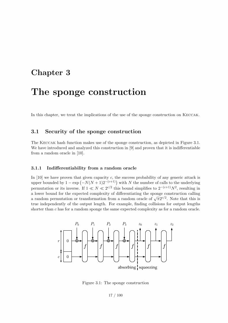
The Keccak hash function makes use of the sponge construction, as depicted in Figure 3.1.We have introduced and analyzed this construction in [9] and proven that it is indifferentiablefrom a random oracle in [10].
3.1.1 Indifferentiability from a random oracle
In [10] we have proven that given capacity c, the success probability of any generic attack isupper bounded by 1− exp
(−N(N + 1)2−(c+1)
)with N the number of calls to the underlying
permutation or its inverse. If 1≪ N ≪ 2c/2 this bound simplifies to 2−(c+1)N2, resulting ina lower bound for the expected complexity of differentiating the sponge construction callinga random permutation or transformation from a random oracle of
√�2c/2. Note that this is
true independently of the output length. For example, finding collisions for output lengthsshorter than c has for a random sponge the same expected complexity as for a random oracle.
Figure 3.1: The sponge construction
17 / 100
Keccak 3. The sponge construction
3.1.2 Indifferentiability of multiple sponge functions
In our SHA-3 proposal we have multiple sponge functions that make use of the same f .The indifferentiability proof of [10] actually only covers the indifferentiability of a singlesponge function instance from a random oracle. In this section we extend this proof toindifferentiability from a set of random oracles of any set of sponge functions with differentcapacity and/or diversifier parameters calling the same f .
Clearly, the best one can achieve is bounded by the strength of the sponge constructioninstance with the smallest capacity, as an adversary can always just try to differentiate theweakest construction from a random oracle. The next theorem states that we achieve thisbound.
Theorem 1. Differentiating an array of padded sponge constructions (Si) according to [11,Algorithm 1] and calling the same random function (resp. permutation) f of width b withdifferent (ci, di) from an array of independent random oracles (ℛOi) has the same successprobability as differentiating a padded sponge construction with capacity mini ci calling a ran-dom function (resp. permutation) f of width b from a random oracle.
Proof: An array (ℛOi) of independent random oracles can be alternatively implemented byhaving a single central random oracle ℛO and simple algorithms Ii that pre-process the inputstrings, so that ℛOi(M) = ℛO(Ii(M)). To simulate independent random oracles, each Iimust produce a different range of output strings, i.e., provide domain separation. In otherwords, the mapping from the couple (i,M) to x = Ii(M) must be injective. This reasoningis also valid if the output of the random oracles is processed by some algorithms Oi thatextracts bits at predefined positions, so that ℛOi(M) = Oi(ℛO(Ii(M))).
In this proof, we will do similarly for the array of padded sponge constructions, by sim-ulating them via a single sponge construction Smin that calls the common random function(or permutation) f . We will then rely on the indifferentiability proof in [10] for the indiffer-entiability between Smin and ℛO.
For Smin, consider the padded sponge construction where the padding simply consists ofthe function pad [11]. This padding satisfies the conditions imposed by the indifferentiabilityproof in [10]. The capacity of Smin is chosen to be cmin = mini ci. In the proof we make useof the bitrates ri that are fully determined by the width b of f and the capacities ci: we haveri = b− ci and denote b− cmin by rmax.
The function Ii is built as follows. The input message M is padded with a single 1 followedby the minimum number of zeroes such that its length becomes a multiple of 8. Then it isfollowed by the binary coding of di and that of ri/8. Subsequently, if ri < rmax, the followingprocessing is performed. The result is split into blocks of ri bits and to each complete blockrmax − ri zeroes are appended. Note that zeroes are appended to the last block only if it iscomplete, i.e., if it has length ri. Finally the blocks are concatenated together again and theresult is x = Ii(M). Due to the fact that the only allowed bitrate values are those multipleof 8, the length of x is a multiple of 8.
The function Oi is built as follows. The output z = Oi(y) is obtained by splitting y inrmax-bit blocks and truncating each block to ri bits.
It follows that each of the functions Si can be simulated as Si(M) = Oi(Smin(Ii(M))).Furthermore, the mapping x = Ii(M) from a triplet (M, ri, di) to x is injective. We demon-strate this by giving an algorithm for reconstructing (M, ri, di) from x. We start by extractingri from x. If the length of x is not a multiple of rmax, no zeroes were added to the last block
18 / 100
3. The sponge construction Keccak
and the binary encoding of ri/8 is in the last byte of x. Otherwise, it is in the last non-zerobyte of x. Now we split x in rmax blocks, truncate each block to its first ri bits, concatenatethem again and call the resulting string m. We can now find the binary encoding of di in thesecond to last byte of m. Finally, we obtain M by removing the two last bytes from m andsubsequently removing the trailing 10∗ bit string.
Differentiating the array (Si) from the array (ℛOi) comes down to differentiating Smin
from ℛO, where Smin has capacity cmin = mini ci.⊓⊔
Note that for the proof to work it is crucial that the inner part (i.e., the c bits unaffectedby the input or hidden from the output, see Section 3.4.1) of the sponge function instancewith the smallest capacity is inside the inner parts of all other sponge function instances.This is realized in our sponge construction by systematically taking as inner part of the stateits last c bits.
So if several sponge construction instances are considered together, only the smallestcapacity counts. When considering a sponge construction instance, one may wonder whetherthe mere existence of a sponge function instance with a smaller capacity has an impact onthe security of that sponge construction. This is naturally not the case, as an adversary hasaccess to f and can simulate any construction imaginable on top of f . What matters is thatthe value N used in the expression for the workload shall include all calls to f and f−1 ofwhich results are used.
3.1.3 Immunity to generic attacks
The indifferentiability result gives us a provable upper bound for the success probability,and hence a provable lower bound for the expected workload of any generic attack. Moreparticularly, for a sponge construction with given c there can be no generic attacks withexpected workload below
√�2c/2.
In the last few years a number of generic attacks against iterated hash functions have beenpublished that demonstrated unexpected weaknesses:
∙ multicollisions [41],
∙ second preimages on n-bit hash functions for much less than 2n work [43],
∙ herding hash functions and the Nostradamus attack [49].
Clearly these attacks are covered by the indifferentiability proof and for a sponge functionthe workload of generic versions of these attacks cannot be below
√�2c/2. As a matter of
fact, all these attacks imply the generation of inner collisions and hence they pose no threat ifgenerating inner collisions is difficult. We will discuss non-generic methods for the generationof inner collisions applicable to Keccak in Section 4.3.
3.1.4 Randomized hashing
Interesting in this context is the application of randomized hashing [57]. Here a signingdevice randomizes the message prior to hashing with a random value that is unpredictableby the adversary. This increases the expected workload of generating a signature that isvalid for two different messages from generating two colliding messages to that of generatinga second pre-image for a message already signed. Now, if we keep in mind that for the
19 / 100
Keccak 3. The sponge construction
sponge construction there are no generic attacks with expected workload of order below 2c/2,we can conclude the following. A lower bound for the expected complexity for generatinga collision is min(2n/2, 2c/2) and for generating a second preimage min(2n, 2c/2). Hence, ifc > 2n, randomization increases the strength against signature forgery due to generic attacksagainst the hash function from 2n/2 to 2n. If the capacity is between n and 2n, the increaseis from 2n/2 to 2c/2. If c < n, randomized hashing does not significantly increase the securitylevel.
3.1.5 Keyed modes
With a random oracle, one can construct a pseudo-random function (PRF) Fk(m) by prepend-ing the message m with a key k, i.e., Fk(m) = ℛO(k∣∣m). In such a case, the function behavesas a random function to anyone not knowing the key k but having access to the same randomoracle. Note that the same reasoning is valid if k is appended to the message.
More specifically, let us consider the following differentiating experiment. In a first world,let the adversary have access to the PRF Fk(m) = ℛO1(k∣∣m) and to the random oracleinstance ℛO1 used by the PRF. In a second world, the adversary has access to two indepen-dent random oracle instances ℛO2 and ℛO3. The adversary has to differentiate the couple(Fk,ℛO1) from the couple (ℛO2,ℛO3). The only statistical difference between the two pairscomes from the identity between Fk(m) and ℛO1(k∣∣m), whereas ℛO2(m) and ℛO3(k∣∣m)give independent results. Therefore, being able to detect such statistical difference means thatthe key k has been recovered. For a key k containing n independent and uniform randombits, the workload to generically recover it is about 2n−1.
As a consequence of the indifferentiability result, the same construction can be used witha sponge function and the same security can be expected when the adversary does not haveaccess to a complexity of order higher than 2c/2.
Note that two options are possible, namely, prepending or appending the key. Prependingthe key prevents the adversary from performing offline computations without access to Fk. Ifthe key is appended, the adversary can for instance generate a state collision (see Section 3.4.1)before querying Fk. The difference between the two options does not make a difference belowthe 2c/2 complexity order bound, though.
3.2 Rationale for the padding
The padding we apply has three purposes:
∙ sponge input preparation,
∙ multi-capacity property,
∙ digest-length dependent digest.
We explain these three purposes in the following subsections.
3.2.1 Sponge input preparation
The padding converts the input string M in an injective way into a string P that satisfies therequirements for the input to an unpadded sponge [9, 10]: the length is a non-zero multiple ofr and the last block is different from 0r. This way, the indifferentiability proof is applicable.
20 / 100
3. The sponge construction Keccak
3.2.2 Multi-capacity property
In the padding the value of the bitrate divided by 8 is binary coded and appended to themessage. This allows to apply the sponge construction to the same permutation with differentcapacity values. Using this padding, the fact that the same f is used for different capacitiesdoes not jeopardize the security of the sponge construction. We have proven in Section 3.1.2that given a random permutation (or transformation) f , for any set of allowed capacity values{c1, c2, . . .}, differentiating the resulting set of sponge functions from a set of random oraclesis not easier than differentiating the sponge function with capacity mini ci from a randomoracle. We have limited the allowed bitrate values to multiples of 8 to limit splitting of inputstrings at byte boundaries. Note that this does not impose restrictions on possible input andoutput lengths.
3.2.3 Digest-length dependent digest
One may have the requirement that a hash function with the same input but requesting adifferent number of output bits shall behave as different hash functions. More particularly,the SHA-3 requirements specify a range of fixed digest lengths while our Keccak spongefunctions in principle have an output with arbitrary length. To achieve this we set the valueof the diversifier d to the digest length expressed in bytes. We have proven in Section 3.1.2 thatgiven a random permutation (or transformation) f , for any set of diversifier values {d1, d2, . . .}and given the capacity c, differentiating the resulting set of sponge functions from a set ofrandom oracles is not easier than differentiating a single sponge function with capacity c froma random oracle.
3.3 Parameter choices
3.3.1 Capacity
In fixed digest-length hash functions, the required resistance against attacks is expressedrelative to the digest length. Until recently one has always found it reasonable to expecta hash function to be as strong as a random oracle with respect to the classical attacks:collisions and (second) preimage. This changed after the publication of the generic attackslisted in Section 3.1.3.
For variable output-length hash functions expressing the required resistance with respectto the output length makes little sense as this would imply that it should be possible toincrease the security level indefinitely by just taking longer digests. In our papers [9, 10], wehave shown that for iterated variable output-length hash functions it is natural to expressthe resistance against attacks with respect to a single parameter called the capacity. Given aflat sponge claim with a specific capacity c, the claim implies that with respect to any attackwith expected complexity below
√�2c/2 the hash function is as strong as a random oracle.
Choosing c = 2n for SHA3-n makes the sponge construction as strong as a random oraclewith respect to the security requirements as specified in [57]. In particular, c = 2n is neededby the requirement that (second) preimage resistance should be at least 2n.
For our recommended SHA-3 candidate Keccak[] we have chosen a capacity of 576 bits.For this choice, the expected workload of an attack should be 2288 calls to the underlyingpermutation. Note that requiring a resistance of 2288 is quite strong, as according to laws
21 / 100
Keccak 3. The sponge construction
of thermodynamics the energy needed by an irreversible computer to perform that manyoperations is unreachable [67, pages 157–158].
3.3.2 Width
The width b of the permutation has been chosen as a trade-off between bitrate and memoryfootprint.
In a straightforward implementation, the RAM footprint is limited to the state and someworking memory. For the 1600-bit version, is still limited to slightly above 200 bytes. More-over, it allows to have a bitrate of 1024 bit and still have a high capacity.
Keccak-f is oriented towards 64-bit CPUs. In applications that are expected to runmainly on 32-bit CPUs, one may consider using Keccak-f [800] in Keccak[r = 256, c = 544]or Keccak[r = 512, c = 288]. The former has a small bitrate, hence impacting its perfor-mance. The latter is twice as fast and has a claimed security level of 2144 with respect toall shortcut attacks. Note that this is higher than the collision resistance claimed today forSHA-224 and SHA-256.
The smallest value of b for which a reasonable level of security can be obtained is b = 200.In our opinion the value of c below which attacks become practical is somewhere between 110and 140, depending on the resources of the adversary.
3.3.3 The default sponge function Keccak[]
One may ask the question: if we can construct arbitrary output-length hash functions, whynot just have a single function and truncate at required length instead of trying to have adifferent hash function per supported output length? This is why we propose Keccak[] as afifth candidate. As said, it has a capacity of 576 bits, a bitrate of 1024 bits and its diversifieris fixed to 0. The capacity and bitrate sum up to 1600, the width of the Keccak-f variantwith lane length of 64 bits, the dominant word length in modern CPUs. For the bitrate wehave chosen the largest power of 2 such that the capacity is not smaller than 512 bits. Notethat the capacity of 576 bits precludes any generic attacks with expected workload below the(astronomical) number 2288.
The default value of the diversifier is 0 as we believe differentiation between versionswith different output lengths is in general not a requirement. Still, we are aware that theremay be schemes in which different hash (or sponge) functions are used that must behaveas different functions, possibly even if they have equal output length. In the latter case,setting the diversifier to the output length does not solve the issue. Rather, in such a case,the requirement that the different instances behave as different functions can be satisfiedby applying domain separation. This can be done by appending or prepending differentconstants to the input for each of the function instances: fi(M) = Keccak[](M ∣∣Ci) orfi(M) = Keccak[](Ci∣∣M). Note that for an appropriate set of constants Ci, Theorem 1 canbe extended to this mode of use.
22 / 100
3. The sponge construction Keccak
3.4 The four critical operations of a sponge
In this section we consider four critical operations that generic attacks on a sponge functionsseem to imply.
3.4.1 Definitions
We call the last c bits of a state S the inner part and we denote it by S.
In the sequel, we make use of the Sf [] function. For a given input string P (after padding),Sf [P ] denotes the value of the state obtained after absorbing P . If s = Sf [P ], we call P a
path to state s (under f). Similarly, if s = Sf [P ] we call P a path to the inner state s. TheSf [] function is defined by the following recursion:
Sf [empty string] =0r∣∣0c,Sf [P ∣∣a] =f (Sf [P ]⊕ (a∣∣0c)) for any string P of length multiple of r
and any r-bit block a .
In general, the j-th r-bit block of a sponge output is
zj = Sf [P ∣∣0jr], j ≥ 0.
The Sf [] function can be used to express the states that the sponge traverses both as itabsorbs an input P and as it is being squeezed. The traversed states are Sf [P ′] for any P ′
prefix of P ∣0∞ with ∣P ′∣ = kr, including the empty string.
Definition 2. A state collision is a pair of different paths P ∕= Q to the same state: Sf [P ] =Sf [Q].
Definition 3. An inner collision is a pair of two different paths P ∕= Q to the same inner
state: Sf [P ] = Sf [Q].
Clearly, a state collision on P ∕= Q implies an inner collision on P ∕= Q. The converse is nottrue. However, in the absorbing phase it is very easy to produce a state collision from an inner
collision. Given P ∕= Q such that Sf [P ] = Sf [Q], the pair P ∣∣a and Q∣∣(a⊕⌊Sf [P ]⊕ Sf [Q]⌋r)forms a state collision for any r-block a.
3.4.2 The operations
The four critical operations are:
∙ finding an inner collision;
∙ finding a path to a given inner state;
∙ finding a cycle in the output: finding an input string P and an integer d > 0 such thatSf [P ] = Sf [P ∣∣0dr];
∙ binding an output string to a state: given a string z with length ∣z∣, finding a statevalue s such that the sponge generates z as output. Here we can distinguish two cases:
23 / 100
Keccak 3. The sponge construction
– Short output string (z ≤ b): the number of possible output strings z is below thenumber of possible states. It is likely that an inner state value can be found, andthe expected number of solutions is ≈ 2b−z.
– Long output string (z > b): the number of possible output strings z is above thenumber of possible states. For a randomly chosen z, the probability that a statevalue may be found is 2b−z. If one is found, it is likely that the inner state valueis unique.
As explained in [9], the classical attacks can be executed as a combination of these operations.In [9] we have discussed generic approaches to these four operations and the correspondingsuccess probabilities.
The optimum algorithm to find an inner collision is to build a rooted tree [9] until a collisionis found. The success probability of this algorithm coincides with the success probability ofdifferentiating the sponge construction calling a random permutation or transformation froma random oracle.
The optimum algorithm to find a path to an inner state for a permutation is to buildtwo trees: a rooted tree and a tree ending in the final inner state. The path is found whena new node in one of the trees is also a node in the other tree. The success probability ofthis algorithm is slightly below that of generating an inner collision. For a transformationthe tree ending in the final inner state cannot be built and the success probability is muchlower. However, both for a transformation as for a permutation, the success probability forfinding a path to an inner state is below that of differentiating the sponge construction froma random oracle.
For a discussion on how to find a cycle or bind an output string to a state, we refer to [9].
24 / 100
Chapter 4
Sponge functions with an iteratedpermutation
The purpose of this chapter is to discuss a number of properties of an iterated permutationthat are particularly relevant when being used in a sponge construction.
4.1 The philosophy
4.1.1 The hermetic sponge strategy
For our Keccak functions we make a flat sponge claim with the same capacity as used inthe sponge construction. This implies that for the claim to stand, the underlying function(permutation or transformation) must be constructed such that it does not allow mountingshortcut attacks that have a higher success probability than generic attacks for the same work-load. We call the design philosophy of adopting a sponge construction using a permutationthat should not have exploitable properties the hermetic sponge strategy.
Thanks to the indifferentiability proof a shortcut attack on a concrete sponge functionimplies a distinguisher for the function (permutation or transformation) it calls. However, adistinguisher for that function does not necessarily imply an exploitable weakness in a spongefunction calling it.
4.1.2 The impossibility of implementing a random oracle
Informally, a distinguisher for a function (permutation or transformation) is the demonstra-tion of any property that sets it significantly apart from a randomly chosen function (per-mutation or transformation). Unfortunately, it is impossible to construct such a functionthat is efficient and has a reasonably sized description or code. It is not hard to see why:any practical b-bit transformation (permutation) has a compact description and implemen-tation not shared by a randomly chosen transformation (or permutation) with its b2b (orlog2 2b! ≈ (b− 1)2b) bits of entropy.
This is better known as the random oracle implementation impossibility and a formalproof for it was first given in [16] and later an alternative proof was given in [53]. In theirproofs, the authors construct a signature scheme that is secure when calling a random oraclebut is insecure when calling a function f taking the place of the random oracle, where the
25 / 100

Keccak 4. Sponge functions with an iterated permutation
function f has a limited (polynomial) running time and can be expressed as a Turing pro-gram of limited size. This argument is valid for any cryptographic function, and so includesKeccak-f . Now, looking more closely at the signature schemes used in [16] and [53], it turnsout that they are especially designed to fail in the case of a concrete function. We find ithard to see how this property in a protocol designed to be robust may lead to its collapse ofsecurity. The proofs certainly have their importance in the more philosophical approach tocryptography, but we don’t believe they prevent the design of cryptographic primitives thatprovide excellent security in well-engineered examples. Therefore, we address the randomoracle implementation impossibility by just making an exception in our security claim.
4.1.3 The choice between a permutation and a transformation
As can be read in [9], the expected workload of the best generic attack for finding a secondpreimage of a message of length ∣m∣ when using a transformation is of the order 2c/∣m∣. Whenusing a permutation this is only of order 2c/2. In that respect, a transformation has preferenceover a permutation. This argument makes sense when developing a hash function dedicatedto offering resistance against second preimage attacks. Indeed, using a transformation allowsgoing for a smaller value of c providing the same level of security against generic attacks.
When developing a general-purpose hash function however, the choice of c is governed bythe security level against the most powerful attack the function must resist, namely collisionattacks. The resistance against output collisions that a sponge function can offer is determinedby their resistance against generating inner collisions. For high values of r, the resistanceagainst generating inner collisions is the same for a transformation or a permutation and ofthe order 2c/2.
4.1.4 The choice of an iterated permutation
Clearly, using a random transformation instead of a random permutation does not offer lessresistance against the four critical operations, with the exception of detecting cycles [9] and thelatter is only relevant if very long outputs are generated. Hence, why choose for a permutationrather than a transformation?
We believe a suitable permutation can be constructed as a fixed-key block cipher: as asequence of simple and similar rounds. A suitable transformation can also be constructed asa block cipher, but here the input of the transformation would correspond with the key inputof the block cipher. This would involve the definition of a key schedule and in our opinionresults in less computational and memory usage efficiency and a more difficult analysis.
Our Keccak functions apply the sponge construction to iterated permutations that aredesigned in the same way as modern block ciphers: iterate a simple nonlinear round func-tion enough times until the resulting permutation has no properties that can be exploited inattacks. The remainder of this chapter deals with such properties and attacks. First, as aniterated permutation can be seen a block cipher with a fixed and known key, it should beimpossible to construct for the full-round versions distinguishers like the known-key distin-guishers for reduced-round versions of DES and AES given in [47]. This includes differentialswith high differential probability (DP), high input-output correlations, distinguishers basedon integral cryptanalysis or deviations in algebraic expressions of the output in terms of theinput. We call this kind of distinguishers structural, to set them apart from trivial distinguish-ers that are of no use in attacks such as checking that f(a) = b for some known input-output
26 / 100
4. Sponge functions with an iterated permutation Keccak
couple (a, b) or the observation that f has a compact description.
In the remainder of this chapter we will discuss some important structural distinguishersfor iterated permutations, identify the properties that are relevant in the critical spongeoperations and finally those for providing resistance to the classical hash function attacks.
4.2 Some structural distinguishers
In this section we discuss structural ways to distinguish an iterated permutation from arandom permutation: differentials with high differential probability (DP), high input-outputcorrelation, non-random properties in the algebraic expressions of the input in terms of theoutput (or vice versa) and the difficulty of solving a particular problem: the constrained-inputconstrained-output problem.
4.2.1 Differential cryptanalysis
A (XOR) differential over a function � consists of an input difference pattern a′ and an outputdifference pattern b′ and is denoted by a couple (a′, b′). A right pair of a differential is a pair{a, a⊕a′} such that �(a⊕a′)⊕�(a) = b′. In general, one can define differentials and (ordered)pairs for any Abelian group operation of the domain and codomain of �. A right (ordered)pair is then defined as {a+ a′, a} such that �(a+ a′) = �(a)⊙ b′, where + corresponds to thegroup operation of the domain of � and ⊙ of its codomain. In the following we will howeverassume that both group operations are the bitwise XOR, or equivalently, addition in ℤb2.
The cardinality of (a′, b′) is the number of right pairs and its differential probability (DP)is the cardinality divided by the total number of pairs with given input difference. We definethe weight of a differential w(a′, b′) as minus the binary logarithm of its DP, hence we haveDP(a′, b′) = 2−w(a′,b′). The set of values a with a a member of a right pair of a differential(a′, b′) can be expressed by a number of conditions on the bits of a. Hence a differentialimposes a number of conditions on the absolute value at its input. In many cases theseconditions can be expressed as w(a′, b′) independent binary equations.
It is well known (see, e.g., [31]) that the cardinality of non-trivial (i.e., with a′ ∕= 0 ∕= b′)differentials in a random permutation operating on ℤn2 with n not very small has a Poissondistribution with � = 1/2 [31]. Hence the cardinality of non-trivial differentials of an iteratedpermutation used in a sponge construction shall obey this distribution.
Let us now have a look at how differentials over iterated mappings are structured. Adifferential trail Q over an iterated mapping f of nr rounds Ri consists of a sequence of nr + 1difference patterns (q0, q1, . . . , qnr). Now let fi = Ri−1 ∘ Ri−2 ∘ . . .R0, i.e., fi consists of thefirst i rounds of �. A right pair of a trail is a couple {a, a ⊕ a′0} such that for all i with0 < i ≤ nr:
fi(a⊕ q0)⊕ fi(a) = qi .
Note that a trail can be considered as a sequence of nr round differentials (qi−1, qi) over eachRi. The cardinality of a trail is the number of right pairs and its DP is the cardinality dividedby the total number of pairs with given input difference. We define the weight of a trail w(Q)as the sum of the weights of its round differentials.
The cardinality of a differential (a′, b′) over f is the sum of the cardinalities of all trails Qwithin that differential, i.e., with q0 = a′ and qnr = b′. From this, the condition on the values
27 / 100
Keccak 4. Sponge functions with an iterated permutation
of the cardinality of differentials of f implies that there shall be no trails with high cardinalityand there shall not be differentials containing many trails with non-zero cardinality.
Let us take a look at the cardinality of trails. First of all, note that DP(Q) = 2−w(Q)
is not necessarily true, although in many cases it may be a good approximation, e.g., whenw(Q) < b − 4. The cardinality of the trail is then given by 2b−1 × DP(Q). Now, whenw(Q) > b−1, we cannot have DP(Q) = 2−w(Q) as the number of pairs is an integer. Typically,a trail with w(Q) > b−1 has no pairs, maybe one pair and very maybe a few pairs. If all trailsover an iterated permutation have weight significantly above b, most pairs will be in a trailthat has only 1 right pair. In other words, trails with more than a single right pair will berare. In those circumstances, finding a trail with non-zero cardinality is practically equivalentto finding a right pair for it. This makes such trails of very small value in cryptanalysis.
If there are no trails with low weight, it remains to be verified that there are no systematicclustering of non-zero cardinality trails in differentials. A similar phenomenon is that oftruncated differentials. These are differentials where the input and output difference patternsare not fully determined. A first type of truncated differentials are especially a concern inciphers where the round function treats the state bits in sets, e.g., bytes. In that case, a typicaltruncated differential only specifies which bytes in the input and/or output difference patternsare passive (equal to zero) and which ones are active (different from zero). The central pointof these truncated differentials is that they also consist of truncated trails and that it may bepossible to construct truncated trails with high cardinality. Similar to ordinary differentialtrails, truncated trails also impose conditions on the bits of the intermediate computationvalues of a, and the number of such conditions can again be quantified by defining a weightfunction.
A second type of truncated differentials are those where part of the output is truncated.Instead of considering the output difference pattern over the complete output of f , one con-siders it over a subset of (say, n of) its output bits (e.g., the inner part f). For a randomb-bit to n-bit function, the cardinality of non-trivial differentials has a normal distributionwith mean 2b−n−1 and variance 2b−n−1 [31]. Again, this implies that there shall be no trailsof the truncated function f with low weight and there shall be no clustering of trails.
Given a trail for f , one can construct a corresponding trail for the truncated version off . This requires exploiting the properties of the round function of f . In general, the trailfor the truncated version will have a weight that is equal to or lower than the original trail.How much lower depends on the round function of f . Typically, the trail in f determinesthe full difference patterns up to the last few rounds. In the last few rounds the differencevalues in some bit positions may become unconstrained resulting in a decrease of the numberof conditions.
4.2.2 Linear cryptanalysis
A (XOR) correlation over a function � consists of an input selection pattern v and an outputselection pattern u and is denoted by a couple (v, u). It has a correlation value denotedby C(v, u) equal to the correlation between the Boolean functions vTa and uT�(a). Thiscorrelation is a real number in the interval [−1, 1]. We define the weight of a correlation by:
w(v, u) = − log2(C2(v, u))/2 .
In general, one can define correlations for any Abelian group operation of the domain andcodomain of �, where C(v, u) is a complex number in the closed unit disk [4]. In the following
28 / 100
4. Sponge functions with an iterated permutation Keccak
we will however assume that both group operations are the bitwise XOR, or equivalently,addition in ℤb2. We only give an introduction here, for more background, we refer to [25].
Correlations in a permutation operating on ℤb2 are integer multiples of 22−b. The distribu-tion of non-trivial correlations (i.e., with u ∕= 0 ∕= v) in a random permutation operating onℤb2 with b not very small has as envelope a normal distribution with mean 0 and variance 2−b
[31]. Hence non-trivial correlations of an iterated permutation used in a sponge constructionshall obey this distribution.
Let us now have a look at how correlations over iterated mappings can be decomposedinto linear trails. A linear trail Q over an iterated mapping f of nr rounds Ri consists of asequence of nr + 1 selection patterns (q0, q1, . . . , qnr). A linear trail can be considered as asequence of nr round correlations (qi, qi+1) over each Ri and its correlation contribution C(Q)consists of the product of the correlations of its round correlations: C(Q) =
∏iC(qi, qi+1).
It follows that C(Q) is a real number in the interval [−1, 1]. We define the weight of a lineartrail by
w(Q) = − log2(C2(Q))/2 =
∑i
w(qi, qi+1) .
A correlation C(v, u) over f is now given by the sum of the correlation contributions of alllinear trails Q within that correlation, i.e., with q0 = v and qnr = u. From this, the conditionon the values of the correlations of f implies that there shall be no trails with high correlationcontribution (so low weight) and there shall not be correlations containing many trails withhigh correlation contributions.
4.2.3 Algebraic expressions
In this secton we discuss distinguishers exploiting particular properties of algebraic expressionsof iterated mappings, more particular that of the algebraic normal form (ANF) consideredover GF(2). In a mapping operating on b bits, one may define a grouping of bits in d-bitblocks for any d dividing b and consider the ANF over GF(2d). The derivations are verysimilar, the only difference is that the coefficients are in GF(2d) rather than GF(2) and thatthe maximum degree of individual variables is 2d − 1 rather than 1.
Let g : GF(2)b → GF(2) be a mapping from b input bits to one output bit. The ANF isthe polynomial
g(x0, . . . , xb−1) =∑
e∈GF(2)b
G(e)xe, with xe =b−1∏i=0
xeii and G(e) ∈ GF(2).
Given the truth table of g(x), one can compute the ANF of g with complexity of O(b2b)as in Algorithm 1.
When g is a (uniformly-chosen) random function, each monomial xe is present with prob-ability one half, or equivalently, G(e) behaves as a uniform random variable over {0, 1} [34].A transformation f : GF(2)b → GF(2)b can be seen as a tuple of b binary functions f = (fi).For a (uniformly-chosen) random transformation, each Fi(e) behaves as a uniform and inde-pendent random variable over {0, 1}.
If f is a random permutation over b bits, each Fi(e) is not necessarily an independentuniform variable. For instance, the monomial of maximal degree x0x1 . . . xb−1 cannot appearsince the bits of a permutation are balanced when x is varied over the whole range GF(2)b.
29 / 100
Keccak 4. Sponge functions with an iterated permutation
Algorithm 1 Computation of the ANF of g(x)
Input g(x) for all x ∈ GF(2)b
Output G(e) for all e ∈ GF(2)b
Define G[t] = G(e), for t ∈ ℕ, when t =∑
i ei2i
Start with G(e)← g(e) for all e ∈ GF(2)b
for i = 0 to b− 1 dofor j = 0 to 2b−i−1 − 1 do
for k = 0 to 2i − 1 doG[2i+1j + 2i + k]← G[2i+1j + 2i + k] +G[2i+1j + k]
end forend for
end for
If b is small, the ANF of the permutation f can be computed explicitly by varying theb bits of input and applying Algorithm 1. A statistical test on the ANF of the output bitfunctions is performed and if an abnormal deviation is found, the permutation f can bedistinguished from a random permutation. Examples of statistical tests on the ANF can befound in [34].
If b is large, only a fraction of the input bits can be varied, the others being set to somefixed value. All the output bits can be statistically tested, though. This can be seen as asampling from the actual, full b-bit, ANF. For instance, let f be obtained by varying only thefirst n < b inputs of f and fixing the others to zero:
f(x0, . . . , xn−1) = f(x0, . . . , xn−1, 0, . . . , 0).
Then, it is easy to see that any monomial xe in the ANF of f also appears in the ANF of f ,and vice-versa, whenever i ≥ n⇒ ei = 0.
A powerful type of attack that exploits algebraic expressions with a low degree are cubeattacks, recently introduced in [32]. Cube attacks recover secret bits from polynomials thattake as input both secret and tweakable public variables. Later cube testers were introducedin [1], that detect nonrandom behaviour rather than perform key extraction and can attackcryptographic schemes described by polynomials of relatively high degree. Cube testers arevery well suited for building structural distinguishers.
4.2.4 The constrained-input constrained-output (CICO) problem
In this section we define and discuss a problem related to f whose difficulty is crucial if itis used in a sponge construction: the constrained-input constrained-output (CICO) problem.Let:
∙ X ⊆ ℤb2: a set of possible inputs.
∙ Y ⊆ ℤb2: a set of possible outputs.
Solving the CICO problem consists in finding a couple (x, y) with y = f(x), x ∈ X and y ∈ Y.
The sets X and Y can be expressed by a number of equations in the bits of x and yrespectively. In the simplest variant, the value of a subset of the bits of x (or y) are fixed. A
30 / 100
4. Sponge functions with an iterated permutation Keccak
similarly simple case is when they are determined by a set of linear conditions on the bits ofx (or y).
We define the weight of X as
w(X ) = b− log2 ∣X ∣,
and w(Y) likewise. When the conditions y = f(x) , x ∈ X and y ∈ Y are considered asindependent, the expected number of solutions is 2b−(w(X )+w(Y)). Note that there may be nosolutions, and this is even likely if w(X ) + w(Y) > b.
The expected workload of solving a CICO problem depends on b, w(X ) and w(Y) but alsoon the nature of the constraints and the nature of f . If we make abstraction of the difficulty offinding members of X or Y, generic attacks impose upper bounds to the expected complexityof solving the CICO problem:
∙ If finding x values in X is easy,
– Trying values x ∈ X until one is found with f(x) ∈ Y is expected to take 2w(Y)
calls to f .
– Trying all values x ∈ X takes 2b−w(X ) calls to f . If there is a solution, it will befound.
∙ If finding y values in Y is easy,
– Trying values y ∈ Y until one is found with f−1(y) ∈ X is expected to take 2w(X )
calls to f−1.
– Trying all values y ∈ Y takes 2b−w(Y) calls to f−1. If there is a solution, it will befound.
When w(X ) or w(Y) is small or close to b, this problem may be generically easy, providedthere is a solution.
In many cases, a CICO problem can be easily expressed as a set of algebraic equations ina set of unknowns and one may apply algebraic techniques for solving these equations suchas Grobner bases [24].
4.2.5 Multi-block CICO problems
The CICO problem can be extended from a single iteration of f to multiple iterations in anatural way. We distinguish two cases: one for the absorbing phase and another one for thesqueezing phase.
An e-block absorbing CICO problem for a function f is defined by two sets X and Y andconsists of finding a solution (x0, x1, x2, . . . xe) such that
x0 ∈ X ,xe ∈ Y ,
for 0 < i < e : xi = 0c ,y1 = f(x0) ,
for 1 < i < e : yi = f(yi−1 ⊕ xi−1) ,xe = f(ye−1 ⊕ xe−1) .
A priori, this problem is expected to have solutions if w(X ) + w(Y) ≤ c+ er.
31 / 100
Keccak 4. Sponge functions with an iterated permutation
An e-block squeezing CICO problem for a function f is defined by e+ 1 sets X0 to Xe andconsists of finding a solution x0 such that:
for 0 ≤ i ≤ e : xi ∈ Xi ,for 0 < i ≤ e : xi = f(xi−1) .
A priori, this problem is expected to have solutions if∑
i w(Xi) < b. If it is known that thereis a solution, it is likely that this solution is unique if
∑i w(Xi) > b.
Note that if e = 1 both problems reduce to the simple CICO problem.
4.2.6 Cycle structure
Consider the infinite sequence a, f(a), f(f(a)), ... with f a permutation over a finite domainand a an element of that set. This sequence is periodic and the set of different elements inthis sequence is called a cycle of f . In this way, a permutation partitions its domain into anumber of cycles.
Statistics of random permutations have been well studied, see [77] for an introduction andreferences. The cycle partition of a permutation used in a sponge construction shall againrespect the distributions. For example, in a random permutation over ℤb2:
∙ The expected number of cycles is b ln 2.
∙ The expected number of fixed points (cycles of length 1) is 1.
∙ The number of cycles of length at most m is about lnm.
∙ The expected length of the longest cycle is aboutG×2b, whereG is the Golomb-Dickmanconstant (G ≈ 0.624).
4.3 Inner collision
Assume we want to generate an inner collision with two single-block inputs. This requiresfinding states a and a∗ such that
f(a)⊕ f(a∗) = 0c with a = a∗ = 0c .
This can be rephrased as finding a right pair {a, a∗} with a = a∗ = 0c for the differential(a ⊕ a∗, 0c) of f . Requiring a = a∗ = 0c is needed to obtain valid paths from the root stateto iteration of f where the differential occurs. In general, it is required to know a path
to the inner state a = a∗ = Sf [P ]; the case a = a∗ = 0c is just a special case of that as
0c = ˆSf [empty string].
4.3.1 Exploiting a differential trail
Assume f is an iterated function and we have a trail Q in f with initial difference a′ andfinal difference b′ such that a′ = b′ = 0c. This implies that for a right pair (a, a∗) of this trail,the intermediate values of a satisfy w(Q) conditions. If w(Q) is smaller than b, the expectednumber of pairs of such a trail is 2b−w.
32 / 100
4. Sponge functions with an iterated permutation Keccak
Let us now assume that given a trail and the value of a, it is easy to find right pairs{a, a⊕ a′} with given a. We consider two cases:
∙ w(Q) < r: it is likely that right pairs exist with a = 0c and an inner collision can befound readily. The paths are made of the first r bits of the members of the found pair,a ∕= a∗.
∙ w(Q) ≥ r: the probability that a right pair exists with a = 0c is 2r−w(Q).
If several trails are available, one can extend this attack by trying it for different trailsuntil a right pair with a = 0c is found. If the weight of trails over f is lower bounded by wmin,the expected workload of this method is higher than 2wmin−r. With this method, differentialtrails do not lead to a shortcut attack if wmin > c/2 + r = b− c/2.
One can extend this attack by allowing more than a single block in the input. In a firstvariant, an initial block in the input is used to vary the inner part of the state and are equalfor both members of the pair that will be found. Given a trail in the second block, theproblem is now to find an initial block that, once absorbed, leads to an inner state at theinput of the trail, for which trail in the second block has a right pair. In other words, thatleads to an inner state that satisfies a number of equations due to the trail in the secondblock. The equations in the second block define a set Y for the output of the first block withw(Y) ≈ w(Q)− r: the conditions imposed by the trail in the second block on the inner partof the state at its input. Moreover, the fact that the inner part of the input to f in the firstiteration is fixed to zero defines a set X with w(X ) = c. Hence, even if a right pair for thetrail can be found, a CICO problem must be solved with w(X ) = c and w(Y) ≈ w(Q)− r fordetermining the first block of the inputs.
Note that if there are no trails with weight below b, the expected number of right pairsper trail is smaller than 1 and trails with more than a single right pair will be rare. In thiscase, even if a trail with a right pair can be found, the generation of an inner collision impliessolving a CICO problem for the first block with w(X ) = w(Y) = c.
One can input pairs that consist of multiple input blocks where there is a difference inmore than a single input block. Here, chained trails may be exploited in subsequent iterationsof f . However, even assuming that the transfer of equations through f due to a trail andconditions at the output is easy, one ends up in the same situation with a number of conditionson the bits of the inner part of the state at the beginning of the first input differential. Andagain, if there are no trails with weight below b, the generation of an inner collision impliessolving a CICO problem with w(X ) = w(Y) = c.
If c > b/2, typically a CICO problem with w(X ) = w(Y) = c will have no solution. Inthat case one must consider multiple blocks and the problem to solve becomes a multi-blockabsorbing CICO problem. The required number of rounds e for there to be a solution is ⌈c/r⌉.
4.3.2 Exploiting a differential
In the search for inner collisions, all right pairs (a, a⊕ a′) with a = 0c of a differential (a′, 0c)with a′ = 0c over f are useful, and not only the pairs of a single trail. So it seems like a goodidea to consider differentials instead of trails. However, where for a given trail it may be easyto determine the pairs that follow it, this is not true in general for a differential. Still, anf -differential may give an advantage with respect to a trail if it contains more than a singletrail with low weight. On the other hand, the conditions to be right pairs of one of a set of
33 / 100

Keccak 4. Sponge functions with an iterated permutation
trails tend to become more complicated as the number of trails grows. This makes algebraicmanipulation more and more difficult as the number of trails to consider grows.
If there are no trails over f with weight below b, the set of right pairs of a differentialis expected to be a set that has no simple algebraic characterization and we expect themost efficient way to determine right pairs is to try different outputs of f with the requireddifference and computing the corresponding inputs.
4.3.3 Truncated trails and differentials
As for ordinary differential trails, the conditions imposed by a truncated trail can be trans-ferred to the input and for finding a collision a CICO problem needs to be solved. Here thefactor w(Y) is determined by the weight of the truncated trail. Similarly, truncated trails canbe combined to truncated differentials and here the same difficulties can be expected as whencombining ordinary trails
4.4 Path to an inner state
If c ≥ b/2, this is simply a CICO problem with w(X ) = w(Y) = c and solving it results ina single-block path to an inner state. If c < b/2, an e-block path to the inner state can befound by solving a multi-block absorbing CICO problem with e = ⌈r/c⌉.
4.5 Detecting a cycle
This is strongly linked to the cycle structure of f . If f is assumed to behave as a randompermutation, the overwhelming majority of states will generate very long cycles. Short cyclesdo exist, but due to the sheer number of states, the probability that this will be observed isextremely low.
4.6 Binding an output to a state
We consider here only the case where the output must fully determine the state. If the capacityis smaller than the bitrate, it is highly probable that a sequence of two output blocks fullydetermines the inner state. In that case, finding the inner state is a CICO problem withw(X ) = w(Y) = r.
If the capacity is larger than the bitrate, one needs more than two output blocks touniquely determine the inner state. Finding the state consists in solving a multi-block squeez-ing CICO problem with w(Xi) = r. The required number of rounds e to uniquely determinethe state is ⌈b/r⌉.
34 / 100
4. Sponge functions with an iterated permutation Keccak
4.7 Classical hash function criteria
In this section we discuss the properties of an iterated permutation that are relevant in theclassical hash function criteria.
4.7.1 Collision resistance
We assume that the sponge function output is truncated to its first n bits and we try togenerate two outputs that are the same for two different inputs. We can distinguish twoways to achieve this: with or without an inner collision. While the effort for generating aninner collision is independent of the length of the output to consider, this is not the case ingeneral for generating output collisions. If n is smaller than the capacity, the generic attackto generate an output collision directly has a smaller workload than generating an innercollision. Otherwise, generating an inner collision and using this to construct a state collisionis expected to be more efficient.
We refer to Section 4.3 for a treatment on inner collisions. With some small adaptations,that explanation also applies to the case of directly generating output collisions. The onlydifference is that for the last iteration of the trail, instead of considering differentials (a′, 0c)over f , one needs to consider differentials (a′, 0n) over ⌊f⌋n. When exploiting a trail, and inthe absence of high-probability trails, this reduces to solving a CICO problem with w(X ) =w(Y) = c to find a suitable first block.
4.7.2 Preimage resistance
We distinguish three cases:
∙ n > b: in this case the output fully determines the state just prior to squeezing. Gener-ating a preimage implies binding a state to an output and subsequently finding a pathto that state. As explained in Sections 4.4 and 4.6, this comes down to solving twoCICO problems.
∙ r < n ≤ b: Here a sequence of input block can in theory be found by solving a problemthat can be seen as a combination of a multi-round squeezing CICO problem and amulti-round absorbing CICO problem.
∙ n ≤ r: A single-block preimage can be found by solving a single-block CICO problemwith w(X ) = c and w(Y) = n.
4.7.3 Second preimage resistance
There are two possible strategies for producing a second preimage. In a first strategy, theadversary can try to find a second path to one of the inner states traversed when absorbingthe first message. Finding a second preimage then reduces to finding a path to a given innerstate [9], which is discussed in Section 4.4. As a by-product, this strategy exhibits an innercollision.
In a second strategy, the adversary can ignore the inner states traversed when absorbingthe first message and instead take into account only the given output. In this case, the firstpreimage is of no use and the problem is equivalent to finding a (first) preimage as discussedin the two last bullets of Section 4.7.2.
35 / 100
Keccak 4. Sponge functions with an iterated permutation
4.7.4 Length extension
Length extension consists in, given ℎ(M) for an unknown input M , being able to predict thevalue of ℎ(M ∣∣x) for some string x. For a sponge function, length extension is successful ifone can find the inner state at the end of the squeezing of M . This comes down to bindingthe output to a state, discussed in Section 4.6. Note that the state is probably only uniquelydetermined if n ≥ b. Otherwise, the expected number of state values the output can be boundto is 2b−n. In that case, the probability of success of length extension is max(2n−b, 2−n).
In principle, if the permutation f has high input-output correlations (v, u) with v = u =0c, this could be exploited to improve the probability of guessing right when doing lengthextension by a single block.
4.7.5 Pseudo-random function
One can use a sponge function with an iterated permutation as a pseudorandom function(PRF) by pre-pending the input by a secret key: PRF[k](M) = sponge(k∣∣M). As explainedin Section 6.1, this can be used to construct MAC functions and stream ciphers. A similarapplication is randomized hashing where an unpredictable value takes the place of the key.
Distinguishing the resulting PRF from a random oracle can be done by finding the key,or by detecting properties in the output that would not be present for a random oracle.Examples of such properties are the detection of large DP values or high correlations over f .If the key is shorter than the bitrate, finding it given the output corresponding to a singleinput is a CICO problem. If the key is longer, this becomes a multi-round absorbing CICOproblem. If more than a single input-output pair is available, this is no longer the case. Ingeneral, an adversary can even request outputs corresponding with adaptively chosen inputs.
When we use a PRF for MAC computation, the length of the key is typically smallerthan the bitrate and the output is limited to (less than) a single output block. For this case,breaking the MAC function can be considered as solving the following generic problem for f .
An adversary can query f for inputs P with P = k∣∣x∣∣0c and
∙ k: an nk-bit secret key,
∙ x: an r − nk-bit value chosen by the adversary,
and is given the first n bits of f(P ), with n ≤ r. The goal of the adversary is predict theoutput of ⌊f(P )⌋n for non-queried values of x with a success probability higher than 2−n.
4.7.6 Output subset properties
One can define an m-bit hash function based on a sponge function by, instead of takingthe m first bits of its output, just specify m bit positions in the output and consider thecorresponding m bits as the output. Such a hash function shall not be weaker than a hashfunction where the m bits are just taken as the first m bits of the sponge output stream. Ifthe m bits are from the same output block, there is little difference between the two functions.If the m bits are taken from different output blocks, the CICO problems implied by attackingthe function tend to become more complicated and are expected to be harder to solve.
36 / 100
Chapter 5
The Keccak-f permutations
This chapter discusses the properties of the Keccak-f permutations that are relevant forthe security of Keccak. After discussing some structural properties, we treat the differentmappings that make up the round function. This is followed by a discussion of differentialand linear cryptanalysis. Subsequently, we briefly discuss the applicability of a number ofcryptanalytic techniques to Keccak-f and the results of some experiments we conducted,mainly on Keccak-f [25]. Finally, we discuss so-called tame trails.
As a reminder, the seven Keccak-f permutations are parameterized by their width b =25w = 25× 2ℓ, for 0 ≤ ℓ ≤ 6.
5.1 Translation invariance
Let b = �(a) with � a mapping that translates the state by 1 bit in the direction of the zaxis. For 0 < z < w we have b[x][y][z] = a[x][y][z − 1] and for z = 0 we have b[x][y][0] =a[x][y][w − 1]. Translating over t bits gives b[x][y][z] = a[x][y][(z − t) mod w]. In general, atranslation � [tx][ty][tz] can be characterized by a vector with three components (tx, ty, tz) andthis gives:
b[x][y][z] = a[(x− tx) mod 5][(y − ty) mod 5][(z − tz) mod w] .
Now we can define translation-invariance.
Definition 4. A mapping � is translation-invariant in direction (tx, ty, tz) if
� [tx][ty][tz] ∘ � = � ∘ � [tx][ty][tz] .
Let us now define the z-period of a state.
Definition 5. The z-period of a state a is the smallest integer d > 0 such that:
∀x, y ∈ ℤ5 and z ∈ ℤw : a[x][y][(z + d) mod w] = a[x][y][z] .
It is easy to prove the following properties:
∙ The z-period of a state divides w.
∙ A state a with z-period d can be represented by w, its z-period d, and its d first slicesa[.][.][z] with z < d. We call this the z-reduced representation of a.
37 / 100
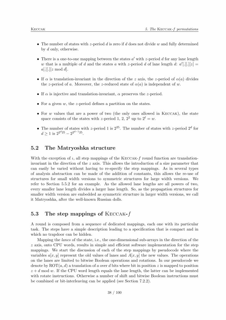
Keccak 5. The Keccak-f permutations
∙ The number of states with z-period d is zero if d does not divide w and fully determinedby d only, otherwise.
∙ There is a one-to-one mapping between the states a′ with z-period d for any lane lengthw that is a multiple of d and the states a with z-period d of lane length d: a′[.][.][z] =a[.][.][z mod d].
∙ If � is translation-invariant in the direction of the z axis, the z-period of �(a) dividesthe z-period of a. Moreover, the z-reduced state of �(a) is independent of w.
∙ If � is injective and translation-invariant, � preserves the z-period.
∙ For a given w, the z-period defines a partition on the states.
∙ For w values that are a power of two (the only ones allowed in Keccak), the statespace consists of the states with z-period 1, 2, 22 up to 2ℓ = w.
∙ The number of states with z-period 1 is 225. The number of states with z-period 2d ford ≥ 1 is 22
d25 − 22d−125.
5.2 The Matryoshka structure
With the exception of �, all step mappings of the Keccak-f round function are translation-invariant in the direction of the z axis. This allows the introduction of a size parameter thatcan easily be varied without having to re-specify the step mappings. As in several typesof analysis abstraction can be made of the addition of constants, this allows the re-use ofstructures for small width versions to symmetric structures for large width versions. Werefer to Section 5.5.2 for an example. As the allowed lane lengths are all powers of two,every smaller lane length divides a larger lane length. So, as the propagation structures forsmaller width version are embedded as symmetric structure in larger width versions, we callit Matryoshka, after the well-known Russian dolls.
5.3 The step mappings of Keccak-f
A round is composed from a sequence of dedicated mappings, each one with its particulartask. The steps have a simple description leading to a specification that is compact and inwhich no trapdoor can be hidden.
Mapping the lanes of the state, i.e., the one-dimensional sub-arrays in the direction of thez axis, onto CPU words, results in simple and efficient software implementation for the stepmappings. We start the discussion of each of the step mappings by pseudocode where thevariables a[x, y] represent the old values of lanes and A[x, y] the new values. The operationson the lanes are limited to bitwise Boolean operations and rotations. In our pseudocode wedenote by ROT(a, d) a translation of a over d bits where bit in position z is mapped to positionz + d mod w. If the CPU word length equals the lane length, the latter can be implementedwith rotate instructions. Otherwise a number of shift and bitwise Boolean instructions mustbe combined or bit-interleaving can be applied (see Section 7.2.2).
38 / 100
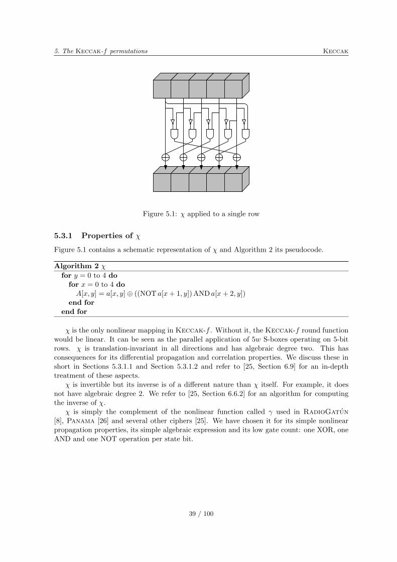
5. The Keccak-f permutations Keccak
Figure 5.1: � applied to a single row
5.3.1 Properties of �
Figure 5.1 contains a schematic representation of � and Algorithm 2 its pseudocode.
Algorithm 2 �
for y = 0 to 4 dofor x = 0 to 4 doA[x, y] = a[x, y]⊕ ((NOT a[x+ 1, y]) AND a[x+ 2, y])
end forend for
� is the only nonlinear mapping in Keccak-f . Without it, the Keccak-f round functionwould be linear. It can be seen as the parallel application of 5w S-boxes operating on 5-bitrows. � is translation-invariant in all directions and has algebraic degree two. This hasconsequences for its differential propagation and correlation properties. We discuss these inshort in Sections 5.3.1.1 and Section 5.3.1.2 and refer to [25, Section 6.9] for an in-depthtreatment of these aspects.
� is invertible but its inverse is of a different nature than � itself. For example, it doesnot have algebraic degree 2. We refer to [25, Section 6.6.2] for an algorithm for computingthe inverse of �.
� is simply the complement of the nonlinear function called used in RadioGatun[8], Panama [26] and several other ciphers [25]. We have chosen it for its simple nonlinearpropagation properties, its simple algebraic expression and its low gate count: one XOR, oneAND and one NOT operation per state bit.
39 / 100
Keccak 5. The Keccak-f permutations
5.3.1.1 Differential propagation properties
Thanks to the fact that � has algebraic degree 2, for a given input difference a′, the space ofpossible output differences forms a linear affine variety [24] with 2w(a′,b′) elements. Moreover,the cardinality of a differential (a′, b′) over � is either zero or a power of two. The corre-sponding (restriction) weight w(a′, b′) = w(a′) is an integer that only depends on the inputdifference pattern a′. A possible differential imposes w(a′) linear conditions on the bits ofinput a.
We now provide a recipe for constructing the affine variety of output difference patternscorresponding to an input difference pattern, applied to a single row. Indices shall be takenmodulo 5 (or in general, the length of the register). We denote by �(i) a pattern with a singlenonzero bit in position i and �(i, j) a pattern with only non-zero bits in positions i and j.
We can characterize the linear affine variety of the possible output differences by an offsetA′ and a basis ⟨cj⟩. The offset is A′ = �(a′). We construct the basis ⟨cj⟩ by adding vectorsto it while running over the all bit positions i:
∙ If a′ia′i+1a
′i+2a
′i+3 ∈ {⋅100, ⋅11⋅, 001⋅}, extend the basis with �(i).
∙ If a′ia′i+1a
′i+2a
′i+3 = ⋅101, extend the basis with �(i, i+ 1).
The (restriction) weight of a difference pattern is equal to its Hamming weight plus the numberof patterns 001. The all-1 input difference pattern results in the affine variety of odd-paritypatterns and has weight 4 (or in general the length of the register minus 1). Among the 31non-zero difference patterns, 5 have weight 2, 15 weight 3 and 11 weight 4.
A differential (a′, b′) leads to a number of conditions on the bits of the absolute value a.Let B = A′⊕ b′ = �(a′)⊕ b′, then we can construct the conditions on a by running over eachbit position i:
∙ a′i+1a′i+2 = 10 imposes the condition ai+2 = Bi .
∙ a′i+1a′i+2 = 11 imposes the condition ai+1 ⊕ ai+2 = Bi .
∙ a′i+1a′i+2 = 01 imposes the condition ai+1 = Bi .
5.3.1.2 Correlation properties
Thanks to the fact that � has algebraic degree 2, for a given output selection vector u,the space of input selection vectors v whose parities have a non-zero correlation with theparity determined by u form a linear affine variety. This variety has 2w(v,u) elements, withw(v, u) = w(u) the (correlation) weight function, which is an even integer that only dependson the output selection pattern u. Moreover, the magnitude of a correlation over � is eitherzero or equal to 2w(u).
We now provide a recipe for constructing the affine variety of input selection patternscorresponding to an output selection pattern, applied to a single row. Indices shall again betaken modulo 5 (or in general, the length of the register). We use the term 1-run of length ℓto denote a sequence of ℓ 1-bits preceded and followed by a 0-bit.
We characterize the linear affine variety with an offset U ′ and a basis ⟨cj⟩ and build theoffset and basis by running over the output selection pattern. First initialize the offset to 0and the basis to the empty set. Then for each of the 1-runs asas+1 . . . as+ℓ−1 do the following:
40 / 100
5. The Keccak-f permutations Keccak
∙ Add a 1 in position s of the offset U ′.
∙ Set i = s, the starting position of the 1-run.
∙ As long as aiai+1 = 11 extend the basis with �(i+ 1, i+ 3) and �(i+ 2), add 2 to i andcontinue.
∙ If aiai+1 = 10 extend the basis with �(i+ 1) and �(i+ 2).
The (correlation) weight of a selection pattern is equal to its Hamming weight plus the numberof 1-runs of odd length. The all-1 output selection pattern results in the affine variety of odd-parity patterns and has weight 4 (or in general the length of the register minus 1). Of the 31non-zero selection patterns, 10 have weight 2 and 21 have weight 4.
5.3.2 Properties of �
Figure 5.2 contains a schematic representation of � and Algorithm 3 its pseudocode.
Algorithm 3 �
for x = 0 to 4 doC[x] = a[x, 0]for y = 1 to 4 doC[x] = C[x]⊕ a[x, y]
end forend forfor x = 0 to 4 doD[x] = C[x− 1]⊕ ROT(C[x+ 1], 1)for y = 0 to 4 doA[x, y] = a[x, y]⊕D[x]
end forend for
The � mapping is linear and aimed at diffusion and is translation-invariant in all directions.Its effect can be described as follows: it adds to each bit a[x][y][z] the bitwise sum of theparities of two columns: that of a[x− 1][⋅][z] and that of a[x+ 1][⋅][z − 1]. Without �, theKeccak-f round function would not provide diffusion of any significance. The � mappinghas a branch number as low as 4 but provides a high level of diffusion on the average. Werefer to Section 5.5.3 for a more detailed treatment of this.
The state can be represented by a polynomial in the three variables x, y and z with binarycoefficients. Here the coefficient of the monomial xiyjzk denotes the value of bit a[i][j][k].The exponents i and j range from 0 to 4 and the exponent k ranges from 0 to w − 1. In thisrepresentation a translation � [tx][ty][tz] corresponds with the multiplication by the monomialxtxytyztz modulo the three polynomials 1+x5, 1+y5 and 1+zw. More exactly, the polynomialrepresenting the state is an element of a polynomial quotient ring defined by the polynomialring over GF(2)[x, y, z] modulo the ideal generated by
⟨1 + x5, 1 + y5, 1 + zw
⟩. A translation
corresponds with multiplication by xtxytyztz in this quotient ring. The z-period of a state ais d if d is the smallest nonzero integer such that 1 + zd divides a. Let a′ be the polynomialcorresponding to the z-reduced state of a, then a can be written as
a = (1 + zd + z2d + . . .+ zw−d)× a′ = 1 + zw
1 + zd× a′ .
41 / 100
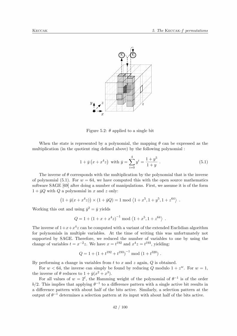
Keccak 5. The Keccak-f permutations
x
y z z
Figure 5.2: � applied to a single bit
When the state is represented by a polynomial, the mapping � can be expressed as themultiplication (in the quotient ring defined above) by the following polynomial :
1 + y(x+ x4z
)with y =
4∑i=0
yi =1 + y5
1 + y. (5.1)
The inverse of � corresponds with the multiplication by the polynomial that is the inverseof polynomial (5.1). For w = 64, we have computed this with the open source mathematicssoftware SAGE [69] after doing a number of manipulations. First, we assume it is of the form1 + yQ with Q a polynomial in x and z only:(
1 + y(x+ x4z))× (1 + yQ) = 1 mod
⟨1 + x5, 1 + y5, 1 + z64
⟩.
Working this out and using y2 = y yields
Q = 1 + (1 + x+ x4z)−1
mod⟨1 + x5, 1 + z64
⟩.
The inverse of 1+x+x4z can be computed with a variant of the extended Euclidian algorithmfor polynomials in multiple variables. At the time of writing this was unfortunately notsupported by SAGE. Therefore, we reduced the number of variables to one by using thechange of variables t = x−2z. We have x = t192 and x4z = t193, yielding:
Q = 1 + (1 + t192 + t193)−1
mod (1 + t320) .
By performing a change in variables from t to x and z again, Q is obtained.For w < 64, the inverse can simply be found by reducing Q modulo 1 + zw. For w = 1,
the inverse of � reduces to 1 + y(x2 + x3).For all values of w = 2ℓ, the Hamming weight of the polynomial of �−1 is of the order
b/2. This implies that applying �−1 to a difference pattern with a single active bit results ina difference pattern with about half of the bits active. Similarly, a selection pattern at theoutput of �−1 determines a selection pattern at its input with about half of the bits active.
42 / 100
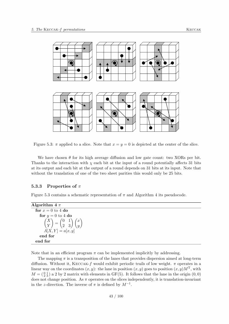
5. The Keccak-f permutations Keccak
Figure 5.3: � applied to a slice. Note that x = y = 0 is depicted at the center of the slice.
We have chosen � for its high average diffusion and low gate count: two XORs per bit.Thanks to the interaction with � each bit at the input of a round potentially affects 31 bitsat its output and each bit at the output of a round depends on 31 bits at its input. Note thatwithout the translation of one of the two sheet parities this would only be 25 bits.
5.3.3 Properties of �
Figure 5.3 contains a schematic representation of � and Algorithm 4 its pseudocode.
Algorithm 4 �
for x = 0 to 4 dofor y = 0 to 4 do(
XY
)=
(0 12 3
)(xy
)A[X,Y ] = a[x, y]
end forend for
Note that in an efficient program � can be implemented implicitly by addressing.
The mapping � is a transposition of the lanes that provides dispersion aimed at long-termdiffusion. Without it, Keccak-f would exhibit periodic trails of low weight. � operates in alinear way on the coordinates (x, y): the lane in position (x, y) goes to position (x, y)MT, withM = ( 0 1
2 3 ) a 2 by 2 matrix with elements in GF(5). It follows that the lane in the origin (0, 0)does not change position. As � operates on the slices independently, it is translation-invariantin the z-direction. The inverse of � is defined by M−1.
43 / 100
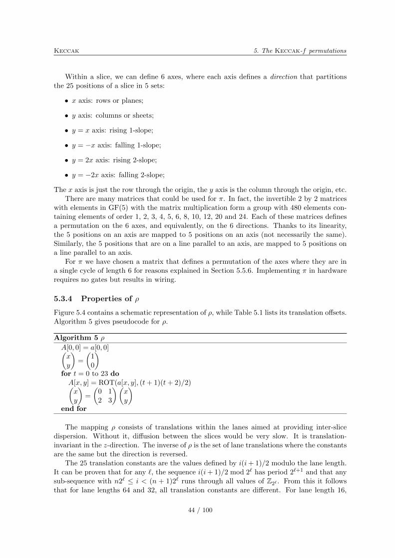
Keccak 5. The Keccak-f permutations
Within a slice, we can define 6 axes, where each axis defines a direction that partitionsthe 25 positions of a slice in 5 sets:
∙ x axis: rows or planes;
∙ y axis: columns or sheets;
∙ y = x axis: rising 1-slope;
∙ y = −x axis: falling 1-slope;
∙ y = 2x axis: rising 2-slope;
∙ y = −2x axis: falling 2-slope;
The x axis is just the row through the origin, the y axis is the column through the origin, etc.There are many matrices that could be used for �. In fact, the invertible 2 by 2 matrices
with elements in GF(5) with the matrix multiplication form a group with 480 elements con-taining elements of order 1, 2, 3, 4, 5, 6, 8, 10, 12, 20 and 24. Each of these matrices definesa permutation on the 6 axes, and equivalently, on the 6 directions. Thanks to its linearity,the 5 positions on an axis are mapped to 5 positions on an axis (not necessarily the same).Similarly, the 5 positions that are on a line parallel to an axis, are mapped to 5 positions ona line parallel to an axis.
For � we have chosen a matrix that defines a permutation of the axes where they are ina single cycle of length 6 for reasons explained in Section 5.5.6. Implementing � in hardwarerequires no gates but results in wiring.
5.3.4 Properties of �
Figure 5.4 contains a schematic representation of �, while Table 5.1 lists its translation offsets.Algorithm 5 gives pseudocode for �.
Algorithm 5 �
A[0, 0] = a[0, 0](xy
)=
(10
)for t = 0 to 23 doA[x, y] = ROT(a[x, y], (t+ 1)(t+ 2)/2)(xy
)=
(0 12 3
)(xy
)end for
The mapping � consists of translations within the lanes aimed at providing inter-slicedispersion. Without it, diffusion between the slices would be very slow. It is translation-invariant in the z-direction. The inverse of � is the set of lane translations where the constantsare the same but the direction is reversed.
The 25 translation constants are the values defined by i(i+ 1)/2 modulo the lane length.It can be proven that for any ℓ, the sequence i(i+ 1)/2 mod 2ℓ has period 2ℓ+1 and that anysub-sequence with n2ℓ ≤ i < (n + 1)2ℓ runs through all values of ℤ2ℓ . From this it followsthat for lane lengths 64 and 32, all translation constants are different. For lane length 16,
44 / 100
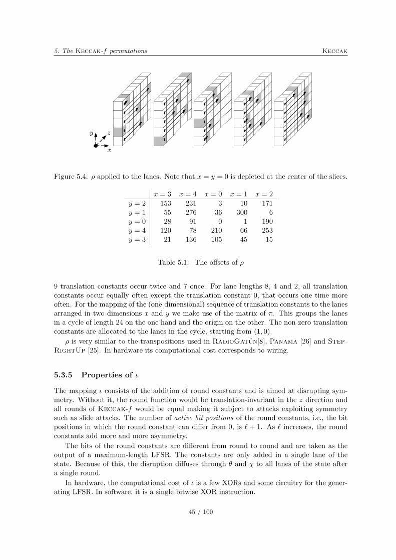
5. The Keccak-f permutations Keccak
Figure 5.4: � applied to the lanes. Note that x = y = 0 is depicted at the center of the slices.
x = 3 x = 4 x = 0 x = 1 x = 2
y = 2 153 231 3 10 171y = 1 55 276 36 300 6y = 0 28 91 0 1 190y = 4 120 78 210 66 253y = 3 21 136 105 45 15
Table 5.1: The offsets of �
9 translation constants occur twice and 7 once. For lane lengths 8, 4 and 2, all translationconstants occur equally often except the translation constant 0, that occurs one time moreoften. For the mapping of the (one-dimensional) sequence of translation constants to the lanesarranged in two dimensions x and y we make use of the matrix of �. This groups the lanesin a cycle of length 24 on the one hand and the origin on the other. The non-zero translationconstants are allocated to the lanes in the cycle, starting from (1, 0).
� is very similar to the transpositions used in RadioGatun[8], Panama [26] and Step-RightUp [25]. In hardware its computational cost corresponds to wiring.
5.3.5 Properties of �
The mapping � consists of the addition of round constants and is aimed at disrupting sym-metry. Without it, the round function would be translation-invariant in the z direction andall rounds of Keccak-f would be equal making it subject to attacks exploiting symmetrysuch as slide attacks. The number of active bit positions of the round constants, i.e., the bitpositions in which the round constant can differ from 0, is ℓ + 1. As ℓ increases, the roundconstants add more and more asymmetry.
The bits of the round constants are different from round to round and are taken as theoutput of a maximum-length LFSR. The constants are only added in a single lane of thestate. Because of this, the disruption diffuses through � and � to all lanes of the state aftera single round.
In hardware, the computational cost of � is a few XORs and some circuitry for the gener-ating LFSR. In software, it is a single bitwise XOR instruction.
45 / 100
Keccak 5. The Keccak-f permutations
5.3.6 The order of steps within a round
The reason why the round function starts with � is due to the usage of Keccak-f in thesponge construction. It provides a mixing between the inner and outer parts of the state.Typically, the inner part is the part that is unknown to, or not under the control of theadversary. The order of the other step mappings is arbitrary.
5.4 Choice of parameters: the number of rounds
We here provide our estimate for our SHA-3 candidates specified in [11, Section 4] of howmany rounds in Keccak-f [1600] are sufficient to provide resistance against four types ofdistinguishers or attacks:
∙ Construction of structural distinguisher for Keccak-f [1600]: 18 rounds.
∙ Construction of structural distinguisher for any of the five candidates: 13 rounds.
∙ Shortcut attack for collision or (second) preimage for any of the five candidates: 11rounds.
∙ Practical generation of an actual collision or (second) preimage for any of the fivecandidates (where the output of Keccak[] is truncated to not less than 256 bits): 9rounds.
These estimates are based on the results of our preliminary analysis that is treated in theremainder of this chapter and the third-party analysis in [2, 52, 3]. By having 24 rounds inKeccak-f [1600], we take a considerable security margin even with respect to the weakestknown structural distinguishers of Keccak-f as published in [3]. In addition, we take a highsecurity margin with respect to structural distinguishers of the Keccak sponge function andthe two types of attack against the five candidates.
5.5 Differential and linear cryptanalysis
5.5.1 Trail propagation
Keccak-f can be seen as the alternation of the nonlinear mapping �, the addition of theround constant �, and a linear mapping � ∘ � ∘ �, that we will denote by �.
Differential trails propagate in the following way. A difference pattern a′ at the input of� determines a linear affine variety of possible difference patterns b′ at its output. This canbe expressed by an offset and a basis with w(a′) elements. The mapping � has no impacton a difference pattern and can be ignored in differential trails. A difference pattern a′ atthe input of � determines the difference pattern b′ at its output by b′ = �(a′). It suffices tospecify one difference pattern per round to fully determine a differential trail. We choose tospecify the difference pattern at the input of �. This has the advantage that the weight ofthe trail is given by the sum of the weights of its difference patterns. An n-round differentialtrail Q defined by the difference patterns (q0, q1, . . . , qn) has weight:
w(Q) =n−1∑i=0
w(qi) .
46 / 100
5. The Keccak-f permutations Keccak
Linear trails propagate in the following way. A selection pattern u at the output of �determines a linear affine variety of possible selection patterns v at its input. Again, this canbe expressed by a basis with w(u) elements and an offset. The mapping � has no impact ona selection pattern. A selection pattern u at the output of � determines the selection patternv at its input. If we express the linear mapping � by the multiplication by a matrix M�,we have v = MT
� u. It suffices to specify one selection pattern per round to fully determinea linear trail. Here we choose to specify the selection pattern at the output of �. This hasthe advantage that the weight of the trail is given by the sum of the weights of its selectionpatterns. An n-round linear trail Q defined by the selection patterns (q0, q1, . . . , qn) hasweight:
w(Q) =n∑i=1
w(qi) .
The magnitude of the correlation contribution of a trail is given by 2−w(Q). The sign is theproduct of the correlations over the � and � steps in the trail. The sign of the correlationcontribution of a linear trail hence depends on the round constants.
5.5.2 The Matryoshka consequence
The weight and existence of trails (both differential and linear) is independent of �. The factthat all other step mappings of the round function are translation-invariant in the directionof the z axis, makes that a trail Q implies w − 1 other trails: those obtained by translatingthe patterns of Q over any non-zero offset in the z direction. If all patterns in a trail have az-period below or equal to d, this implies only d− 1 other trails.
Moreover, a trail for a given width b implies a trail for all larger widths b′. The patternsare just defined by their z-reduced representations and the weight must be multiplied by b′/b.Note that this is not true for the cardinality of differential trails and the sign of the correlationcontribution of linear trails, as these do depend on the round constants.
5.5.3 The column parity kernel
The mapping � is there to provide diffusion. As said, it can be expressed as follows: add toeach bit a[x][y][z] the bitwise sum of the parities of two columns: that of a[x− 1][⋅][z] andthat of a[x+ 1][⋅][z − 1]. From this we can see that for states in which all columns have evenparity, � is the identity. We call this set of states the column parity kernel or CP-kernel forshort.
The size of the CP-kernel is 220w as there are in total 2b = 225w states and there are 25w
independent parity conditions. The kernel contains states with Hamming weight values aslow as 2: those with two active bits in a single column. Due to these states, � only has abranch number (expressed in Hamming weight) of 4.
The low branch number is a consequence of the fact that only the column parities prop-agate. One could consider changing � to improve the worst-case diffusion, but this wouldsignificantly increase the computational cost of � as well. Instead, we have chosen to addressthe CP-kernel issue by carefully choosing the mapping �.
We can compute from a 25w-bit state its 5w-bit column parity pattern. These patternspartition the state space in 25w subsets, called the parity classes, with each 220w elements.We can now consider the branch number restricted to the states in a given parity class. As
47 / 100
Keccak 5. The Keccak-f permutations
said, the minimum branch number that can occur is 4 for the CP-kernel, the parity class withthe all-zero column parity pattern. Over all other parity classes, the branch number is atleast 12.
Note that for states where all columns have odd parity, � adds 0 to every bit and also actsas the identity. However, the Hamming weight of states in the corresponding parity class isat least 5w resulting in a branch number of 10w.
5.5.4 One and two-round trails
Now we will have a look at minimum weights for trails with one and two rounds. The minimumweight for a one-round differential trail (q0, q1) is obtained by taking a difference pattern q0with a single active bit and has weight 2. For a linear trail this is obtained by a selectionpattern q1 with a single active bit or two neighboring active bits in the same row, and theweight is also 2. This is independent of the width of Keccak-f .
For the minimum weight of two-round trails we use the following property of �: if adifference pattern at the input of � restricted to a row has a single active bit, the samedifference pattern is a possible difference pattern at its output. Hence for difference patternswith zero or one active bits per row, � can behave as the identity. Similarly, for selectionpatterns with zero or one active bits per row, � can behave as the identity. We call such trailsin which the patterns at the input and output of � are the same, �-zero trails. Note that allpatterns in a �-zero trail are fully determined by the first pattern q0.
For all widths, the two-round trails with minimum weight are �-zero trails. For a differ-ential trail, we choose for q0 a difference pattern with two active bits that are in the samecolumn. After � the difference pattern has not changed and as it is in the CP-kernel, it goesunchanged through � as well. The mappings � and � move the two active bits to differentcolumns, but in no case to the same row. This results in a value of q1 with two active bitsin different rows. As the weight of both q0 and q1 is 4, the resulting trail has weight 8. Forlinear trails, a similar reasoning applies and the minimum trail weight is also 8. Note thatthe low weight of these trails is due to the fact that the difference pattern at the input of �in round 0 is in the CP-kernel.
5.5.5 Three-round trails: kernel vortices
From here on, we concentrate on differential trails as the explanation is very similar for lineartrails. We can construct a three-round �-zero trail where both difference patterns q0 and q1are in the CP-kernel. As in a �-zero trail � behaves as the identity and q0 is in the CP-kernel,we have q1 = �(�(q0)). Hence, we can transfer the conditions that q0 is in the kernel toconditions on q1, or vice versa.
We will now look for patterns q0 where both q0 and �(�(q0)) are in the CP-kernel. q0cannot be a pattern with only two active bits in one column since � ∘ � maps these bits totwo different columns in q1.
The minimum number of active bits in q0 is four, where both q0 and q1 have two activecolumns with each two active bits. We will denote these four active bits as points 0, 1, 2 and3. Without loss of generality, we assume these points are grouped two by two in columnsin q0: {0, 1} in one column and {2, 3} in another one. In q1 we assume they are grouped incolumns as {1, 2} and {3, 0}.
48 / 100
5. The Keccak-f permutations Keccak
The mapping � maps sheets (containing the columns) to falling 2-slopes and maps planesto sheets. Hence the points {0, 1} and {2, 3} are in falling 2-slopes in q1 and the points{1, 2} and {3, 0} are in planes in q0. This implies that projected on the (x, y) plane, the fourpoints of q0 form a rectangle with horizontal and vertical sides. Similarly, in q1 they form aparallelogram with vertical sides and sides that are falling 2-slopes.
The (x, y) coordinates of the four points in q0 are completely determined by those of thetwo opposite corner points (x0, y0) and (x2, y2). The four points have coordinates: (x0, y0),
(x0, y2), (x2, y2) and (x2, y0). The number of possible choices is(25
)2= 100. Now let us have
a look at their z coordinates. Points 0 and 1 should be in the same column and points 2 and3 too. Hence z1 = z0 and z3 = z2. Moreover, � shall map points 1 and 2 to the same sliceand bits 3 and 0 too. This results in the following conditions for their z-coordinates:
z0 + r[x0][y2] = z2 + r[x2][y2] modw ,z2 + r[x2][y0] = z0 + r[x0][y0] modw ,
(5.2)
with r[x][y] denoting the translation offset of � in position (x, y). They can be converted tothe following two conditions:
z2 = z0 + r[x0][y2]− r[x2][y2] modw ,z2 = z0 + r[x0][y0]− r[x2][y0] modw .
In any case z0 can be freely chosen, and this determines z2. Subtracting these two equationseliminates z0 and z2 and results in:
r[x0][y0]− r[x0][y2] + r[x2][y2]− r[x2][y0] = 0 mod w . (5.3)
If this equation is not satisfied, the equations (5.2) have no solution.
Consider now w = 1. In that case Equation (5.3) is always satisfied. However, in order tobe �-zero, the points must be in different rows, and hence in different planes, both in q0 andq1, and this is not possible for a rectangle.
If ℓ ≥ 1, Equation (5.3) has a priori a probability of 2−ℓ of being satisfied. Hence, wecan expect about 2−ℓ100 rectangles to define a state q0 with both q0 and �(�(q0)) in theCP-kernel. So it is not inconceivable that such patterns exists for w = 64. This would resultin a 3-round trail with weight of 8 per round and hence a total weight of 24. However, forour choice of � and �, there are no such trails for w > 16.
Note that here also the Matryoshka principle plays. First, the z-coordinate of one ofthe points can be freely chosen and determines all others. So, given a rectangle that has asolution for Equation (5.3), there are 2ℓ patterns q0, one for each choice of z0. Second, ifEquation (5.3) is not satisfied for ℓ but it is for some ℓ′ < ℓ, it implies a pattern q0 with 2ℓ−ℓ
′4
points rather than 4 for which both q0 and �(�(q0)) are in the kernel.
These patterns can be generalized by extending the number of active bits: a pattern q0with both q0 and �(�(q0)) in the kernel can be constructed by arranging 2e points in a cyclein the (x, y) plane and giving the appropriate z-coordinates. In such a cycle each combinationof points {2i, 2i+ 1} are in the same sheet and each combination of points {2i+ 1, 2i+ 2} arein the same plane. We call such a cycle of 2e (x, y) positions a kernel vortex V .
For the z coordinates, the conditions that the points {2i, 2i+ 1} are in the same columnin q0 and the points {2i + 1, 2i + 2} are in the same column in q1 results in 2e conditions.Similar to the rectangle case, these conditions only have a solution if the � rotation constants
49 / 100
Keccak 5. The Keccak-f permutations
in the lanes of the cycle satisfy a condition. For a given kernel vortex V , we define its depthd(V ) as:
d(V ) =
2e−1∑i=0
(−1)ir[point i]. (5.4)
Now, the vortex results in a valid pattern q0 if d(V ) mod w = 0. We call the largest powerof 2 dividing d(V ) the character of the vortex c(V ). If d(V ) = 0, we say its character isc(V ) = ∞. Summarizing, a vortex V defines a valid pattern q0 with 2e active bits for lanelength w ≤ c(V ). For constructing low-weight 3-round trails, it suffices to find vortices withsmall e and large character: given a vortex V it results in a 3-round trail with weight 12efor all values of 2ℓ ≤ c(V ) and with weight 12e2ℓ/c(V ) for all values of 2ℓ > c(V ) (usingsymmetric trails of period c(V )).
As the length of vortices grows, so does their number. There are 600 vortices of length6, 8400 of length 8 and 104040 of length 10. The character c(V ) over these vortices has anexponential distribution: about half of them has character 1, 1/4 have character 2, 1/8 havecharacter 4 and so on. It follows that as their length 2e grows, there are more and morevortices that result in valid pattern q0 with 2e active bits, even for lane length 64.
Moreover, one can construct patterns q0 containing two or more vortices, provided thatthey do not result in a row with two active bits in either q0 or q1. The character of such acombination is just the minimum of the characters of its component vortices. Clearly, due thelarge number of kernel vortices, it is likely that there are three-round trails with low weightfor any choice of � and �. For our choice of � and �, the vortex that leads to the 3-roundtrail with the smallest weight for Keccak-f is one of length 6 and character 64. It results ina 3-round trail with weight 36.
5.5.6 Beyond three-round trails: choice of �
We will now try to extend this to four-round trails: we try to find patterns q0 such that q0,q1 and q2 are in the CP-kernel.
A vortex of length 4, i.e., with e = 2 cannot do the job with our choice of �: a rectanglein q0 with sheets and planes as sides results in a parallelogram in q1 with falling 2-slopes andcolumns as sides and in a parallelogram in q2 with rising 2-slopes and falling 2-slopes as sides.Hence the four points in q2 cannot grouped in columns 2 by 2 and therefore it cannot be inthe kernel.
Consider now a vortex of length 6. We choose the points such that the grouping in columnsis {0, 1}, {2, 3}, {4, 5} in q0, it is {1, 2}, {3, 4}, {5, 0} in q1 and {1, 4}, {2, 5}, {3, 0} in q2. Thegrouping in q1 simply implies that {1, 2}, {3, 4}, {5, 0} are grouped in planes in q0. Actually,the first two groupings are similar to the three-round trail case: they determine a characterc(V ) and fix the z coordinates of all points but one. We will now study the implications of thegrouping in q2 on the (x, y) coordinates. Grouping in columns (sheets) in q2 implies groupingin planes in q1 and subsequently grouping in rising 1-slopes in q0.
For the z-coordinates this results in 3 additional conditions: points 1 and 4, points 2 and5 and points 3 and 0 must have the same z-coordinate in q2. Similar to Equation (5.2) theseconditions are equalities modulo 2ℓ. For each of the equations, the a priori probability that itis satisfied for a given value of 2ℓ is 2−ℓ. With each of these equations we can again associatea character: the largest value w that is a power of two for which the equation is satisfied. The4-round character (i.e. leading to q0, q1 and q2 all three in the kernel) of the vortex in this
50 / 100
5. The Keccak-f permutations Keccak
context is now the minimum of the 3-round character (i.e. leading to both q0 and q1 in thekernel) of the vortex and the characters of the three additional equations. The probabilitythat the 4-round character is larger than 2ℓ is approximately 2−4(ℓ+1). It turns out that forour choice of � and �, 8 of the 50 candidate vortices have 4-round character 2 and the othershave all 4-round character 1.
The conditions on the (x, y) coordinates imply that only vortices are suited that have aneven number of active points in each sheet, each plane and each rising 1-slope. This limits thenumber of suitable vortices of length 6 to 50, of length 8 to 300, of length 10 to 4180 and oflength 12 to 53750. To illustrate this, let us now study the number of activity patterns in the(x, y) coordinates of q0 assuming there is only a single active bit in each lane. In total thereare 225 − 1 nonzero patterns. If we impose the pattern to be in the CP-kernel, the parityof each sheet must be even, resulting in 5 independent linear equations. Hence there are220 − 1 patterns in the kernel. Additionally requiring q1 to be in the kernel imposes that thenumber of points in each plane of q0 must be even. This adds 5 parity conditions. However,one is redundant with the ones due to q0 as the total parity of the activity pattern over thestate is even. Hence there are 216 − 1 such patterns. Additionally requiring q2 to be in thekernel imposes that the number of points in each rising 1-slope of q0 must be even. Thisadds again 5 new parity condition, with one of them redundant and reduces the number ofpossible patterns to 212 − 1. Since � runs through all directions, adding more rounds resultsin 28 − 1, and 24 − 1 and finally 0 patterns. It follows that the range of possible activitypatterns shrinks exponentially as the number of rounds grows.
This is the main reason for choosing a � that runs through all axes in a single cycle.Consider a � that would map sheets to rising 1-slopes and rising 1-slopes back to sheets. Forsuch a � there would be 216 − 1 activity patterns with q0, q1 and q2 in the kernel. Moreover,this number would not decrease for more rounds and periodic �-zero trails of low weight mightappear.
When trying vortices with length above 6, the conditions on the z coordinates can bemore involved. If in a particular sheet of q2 the number of active points is 2, the condition isthe same as for the case described above: their z coordinates should match. However, if thereare 4, 6 or any even number of active points, there are several ways for them to be grouped indifferent columns. In general a character can be computed per sheet and the character of thecomplete structure is the minimum of all these characters. The character for a given sheetcan be computed in a recursive way. The probability that an active sheet has character 1is 1/2. For larger characters, the probability decreases faster with growing number of activebits in the character.
We have done tests for vortex lengths up to 14 and for constructions making use of twovortices totaling to about 1 million valid q0 patterns. The vast majority have character1, less than 13000 have character 2, 103 have character 4 and one has character 8. Thislast one is based on vortex of length 8 and it results in a 4-round trail with weight 512 inKeccak-f [1600].
5.5.7 Truncated trails and differentials
Truncated trails deal with the propagation of activity patterns rather than difference patterns[46]. A partition of the state in sub-blocks is defined where the activity patterns describewhether a sub-block has no active bits (passive or 0) or has at least one active bit (active or1). The structure of the state in Keccak-f suggests several bundlings. In a first order, one
51 / 100
Keccak 5. The Keccak-f permutations
may take rows, columns, lanes, sheets, planes or slices as sub-blocks. We have gone throughan exercise of attempting this but got stuck very soon for each of the choices. The problem isthat for every choice, at least one of the step mappings completely tears apart the sub-blocks.We have also considered hybrid state definitions, such as the combination of row activitieswith column parities. However, in the cases that could be interesting, i.e., states with lowweight (with respect to the truncation considered), this soon lead to the full specification ofthe difference.
In [44] truncated cryptanalysis was applied to RadioGatun [8], where the truncationwas defined by a linear subspaces of the word vectors. In the attack it made sense as partof the RadioGatun round function is linear. In Keccak-f the round function is uniformlynon-linear and we do not believe that this approach can work.
5.5.8 Other group operations
We have considered differential and linear cryptanalysis while assuming the bitwise additionas the group operation. One may equivalently consider differential and linear properties withrespect to a wide range of other group operations that can be defined on the state. However,for any other choice than the bitwise addition, � becomes a nonlinear function and for mostchoices also �, � and � become nonlinear. We do not expect this to lead to better results.
5.5.9 Differential and linear cryptanalysis variants
There are many attacks that use elements from differential cryptanalysis and/or linear crypt-analysis. Most are applied to block ciphers to extract the key. We have considered a numberof techniques:
∙ Higher-order differentials [46]: we believe that due to the high average diffusion it isvery difficult to construct higher-order differentials of any significance for Keccak-f .
∙ Impossible differentials [76]: we expect the Keccak-f permutations to behave as ran-dom permutations. If so, the cardinality of differentials has a Poisson distribution with� = 1/2 [31] and hence about 60 % of the differentials in Keccak-f will have cardinality0, and so are impossible. However, given a differential (a, b), it is a priori hard to predictwhether it is impossible. Settings in which one could exploit impossible differentials arekeyed modes, where part of the input is fixed and unknown. In this case one wouldneed truncated impossible differentials. If the number of rounds is sufficient to avoidlow-weight differential trails, we believe this can pose no problem.
∙ Differential-linear attacks [51]: in these attacks one concatenates a differential over anumber of rounds and a correlation over a number of subsequent rounds. We thinkthat for reduced-round versions of Keccak-f differential-linear distinguishers are acandidate for the most powerful structural distinguisher. The required number of pairsis of the order DP−2LP−2 with DP the differential probability of the distinguisher’sdifferential and LP the square of the distinguisher’s correlation. If we assume thedifferentials is dominated by a single low-weight differential trail, we have DP ≈ 2−w(Qd).Additionally, if we assume the correlation is dominated by a single low-weight lineartrail, we have DP ≈ 2−w(Ql). This gives for the number of required pairs: 22(w(Qd)+w(Ql)).The number of required pairs to exploit a trail in a simple differential or linear attack is
52 / 100
5. The Keccak-f permutations Keccak
DC LCNumber of rounds w = 1 w = 2 w = 1 w = 2
2 8 8 8 8
3 16 18 16 16
4 23 29 24 30
5 30 42 30 40
6 37 54 38 52
Table 5.2: Lower bounds for trail weights
of the order 2w(Q). Hence, over a number of rounds, the differential-linear distinguisheris more powerful than a simple differential or linear distinguisher if w(Qd) + w(Ql) <w(Q)/2. Where Q is a trail over all rounds, Qd a trail of the first n rounds and Ql a trailover the remaining rounds. As we expect in the Keccak-f variants with large widthand a low number of rounds, the minimum trail weight tends to grow exponentially,and the chaining of two half-length trails is favored over a single full-length trail.
∙ (Amplified) Boomerang [73, 42] and rectangle attacks [14]: These attacks chain (setsof) differentials over a small number of rounds to construct distinguishers over a largernumber of rounds. These are also likely candidates for good structural distinguishers,for the same reason as differential-linear ones.
∙ Integral cryptanalysis (Square attacks) [27]: this type of cryptanalysis lends itself verywell to ciphers that treat the state in blocks. It was applied to bit-oriented ciphersin [78]. Based on the findings of that paper we estimate that it will only work onreduced-round versions of Keccak-f with three to four rounds.
In this section we have limited ourselves to the construction of structural distinguishers. Wehave not discussed how these distinguishers can be used to attack the sponge function makinguse of the permutation.
5.5.10 Bounds for symmetric trails
We have performed a pruned tree search for low-weight trails for widths 25 and 50 that resultin the lower bounds in Table 5.2. For b = 25, five rounds are sufficient to have no trails withweight below the width. For b = 50, six rounds are sufficient to have no differential trailswith weight below the width. It can be observed that as the number of rounds grows, thedifference between width 25 and width 50 grows. We expect this effect to be similar for largerwidths.
Note that thanks to the Matryoshka structure, these bounds imply lower bounds forsymmetric trails for all larger widths. More specifically, a trail for w = 1 with weight Wcorresponds with a trail for w = 2ℓ with weight wW = 2ℓW .
5.6 Solving CICO problems
There are several approaches to solving a CICO problem for Keccak-f . The most straight-forward way is to use the Keccak-f specification to construct a set of algebraic equations in
53 / 100
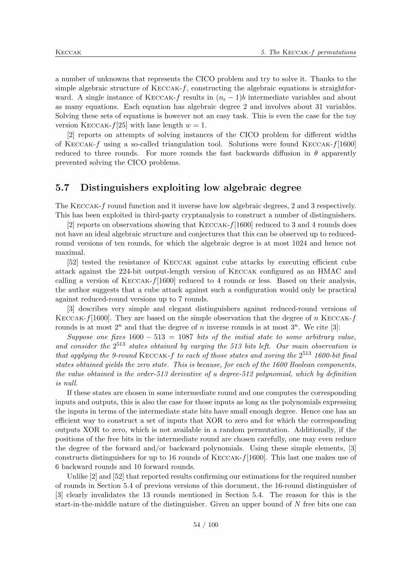
Keccak 5. The Keccak-f permutations
a number of unknowns that represents the CICO problem and try to solve it. Thanks to thesimple algebraic structure of Keccak-f , constructing the algebraic equations is straightfor-ward. A single instance of Keccak-f results in (nr − 1)b intermediate variables and aboutas many equations. Each equation has algebraic degree 2 and involves about 31 variables.Solving these sets of equations is however not an easy task. This is even the case for the toyversion Keccak-f [25] with lane length w = 1.
[2] reports on attempts of solving instances of the CICO problem for different widthsof Keccak-f using a so-called triangulation tool. Solutions were found Keccak-f [1600]reduced to three rounds. For more rounds the fast backwards diffusion in � apparentlyprevented solving the CICO problems.
5.7 Distinguishers exploiting low algebraic degree
The Keccak-f round function and it inverse have low algebraic degrees, 2 and 3 respectively.This has been exploited in third-party cryptanalysis to construct a number of distinguishers.
[2] reports on observations showing that Keccak-f [1600] reduced to 3 and 4 rounds doesnot have an ideal algebraic structure and conjectures that this can be observed up to reduced-round versions of ten rounds, for which the algebraic degree is at most 1024 and hence notmaximal.
[52] tested the resistance of Keccak against cube attacks by executing efficient cubeattack against the 224-bit output-length version of Keccak configured as an HMAC andcalling a version of Keccak-f [1600] reduced to 4 rounds or less. Based on their analysis,the author suggests that a cube attack against such a configuration would only be practicalagainst reduced-round versions up to 7 rounds.
[3] describes very simple and elegant distinguishers against reduced-round versions ofKeccak-f [1600]. They are based on the simple observation that the degree of n Keccak-frounds is at most 2n and that the degree of n inverse rounds is at most 3n. We cite [3]:
Suppose one fixes 1600 − 513 = 1087 bits of the initial state to some arbitrary value,and consider the 2513 states obtained by varying the 513 bits left. Our main observation isthat applying the 9-round Keccak-f to each of those states and xoring the 2513 1600-bit finalstates obtained yields the zero state. This is because, for each of the 1600 Boolean components,the value obtained is the order-513 derivative of a degree-512 polynomial, which by definitionis null.
If these states are chosen in some intermediate round and one computes the correspondinginputs and outputs, this is also the case for those inputs as long as the polynomials expressingthe inputs in terms of the intermediate state bits have small enough degree. Hence one has anefficient way to construct a set of inputs that XOR to zero and for which the correspondingoutputs XOR to zero, which is not available in a random permutation. Additionally, if thepositions of the free bits in the intermediate round are chosen carefully, one may even reducethe degree of the forward and/or backward polynomials. Using these simple elements, [3]constructs distinguishers for up to 16 rounds of Keccak-f [1600]. This last one makes use of6 backward rounds and 10 forward rounds.
Unlike [2] and [52] that reported results confirming our estimations for the required numberof rounds in Section 5.4 of previous versions of this document, the 16-round distinguisher of[3] clearly invalidates the 13 rounds mentioned in Section 5.4. The reason for this is thestart-in-the-middle nature of the distinguisher. Given an upper bound of N free bits one can
54 / 100
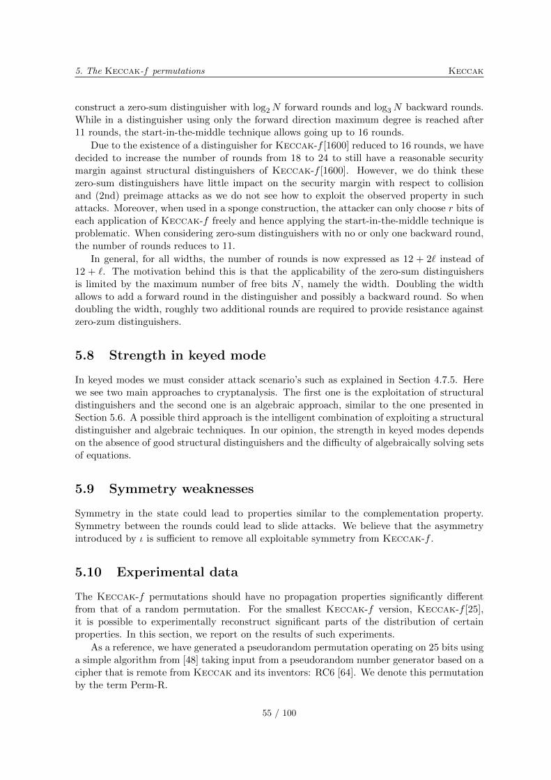
5. The Keccak-f permutations Keccak
construct a zero-sum distinguisher with log2N forward rounds and log3N backward rounds.While in a distinguisher using only the forward direction maximum degree is reached after11 rounds, the start-in-the-middle technique allows going up to 16 rounds.
Due to the existence of a distinguisher for Keccak-f [1600] reduced to 16 rounds, we havedecided to increase the number of rounds from 18 to 24 to still have a reasonable securitymargin against structural distinguishers of Keccak-f [1600]. However, we do think thesezero-sum distinguishers have little impact on the security margin with respect to collisionand (2nd) preimage attacks as we do not see how to exploit the observed property in suchattacks. Moreover, when used in a sponge construction, the attacker can only choose r bits ofeach application of Keccak-f freely and hence applying the start-in-the-middle technique isproblematic. When considering zero-sum distinguishers with no or only one backward round,the number of rounds reduces to 11.
In general, for all widths, the number of rounds is now expressed as 12 + 2ℓ instead of12 + ℓ. The motivation behind this is that the applicability of the zero-sum distinguishersis limited by the maximum number of free bits N , namely the width. Doubling the widthallows to add a forward round in the distinguisher and possibly a backward round. So whendoubling the width, roughly two additional rounds are required to provide resistance againstzero-zum distinguishers.
5.8 Strength in keyed mode
In keyed modes we must consider attack scenario’s such as explained in Section 4.7.5. Herewe see two main approaches to cryptanalysis. The first one is the exploitation of structuraldistinguishers and the second one is an algebraic approach, similar to the one presented inSection 5.6. A possible third approach is the intelligent combination of exploiting a structuraldistinguisher and algebraic techniques. In our opinion, the strength in keyed modes dependson the absence of good structural distinguishers and the difficulty of algebraically solving setsof equations.
5.9 Symmetry weaknesses
Symmetry in the state could lead to properties similar to the complementation property.Symmetry between the rounds could lead to slide attacks. We believe that the asymmetryintroduced by � is sufficient to remove all exploitable symmetry from Keccak-f .
5.10 Experimental data
The Keccak-f permutations should have no propagation properties significantly differentfrom that of a random permutation. For the smallest Keccak-f version, Keccak-f [25],it is possible to experimentally reconstruct significant parts of the distribution of certainproperties. In this section, we report on the results of such experiments.
As a reference, we have generated a pseudorandom permutation operating on 25 bits usinga simple algorithm from [48] taking input from a pseudorandom number generator based on acipher that is remote from Keccak and its inventors: RC6 [64]. We denote this permutationby the term Perm-R.
55 / 100
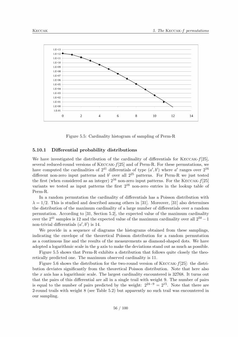
Keccak 5. The Keccak-f permutations
1.E-01
1.E+00
1.E+01
1.E+02
1.E+03
1.E+04
1.E+05
1.E+06
1.E+07
1.E+08
1.E+09
1.E+10
1.E+11
1.E+12
1.E+13
0 2 4 6 8 10 12 14
Figure 5.5: Cardinality histogram of sampling of Perm-R
5.10.1 Differential probability distributions
We have investigated the distribution of the cardinality of differentials for Keccak-f [25],several reduced-round versions of Keccak-f [25] and of Perm-R. For these permutations, wehave computed the cardinalities of 241 differentials of type (a′, b′) where a′ ranges over 216
different non-zero input patterns and b′ over all 225 patterns. For Perm-R we just testedthe first (when considered as an integer) 216 non-zero input patterns. For the Keccak-f [25]variants we tested as input patterns the first 216 non-zero entries in the lookup table ofPerm-R.
In a random permutation the cardinality of differentials has a Poisson distribution with� = 1/2. This is studied and described among others in [31]. Moreover, [31] also determinesthe distribution of the maximum cardinality of a large number of differentials over a randompermutation. According to [31, Section 5.2], the expected value of the maximum cardinalityover the 241 samples is 12 and the expected value of the maximum cardinality over all 250− 1non-trivial differentials (a′, b′) is 14.
We provide in a sequence of diagrams the histograms obtained from these samplings,indicating the envelope of the theoretical Poisson distribution for a random permutationas a continuous line and the results of the measurements as diamond-shaped dots. We haveadopted a logarithmic scale in the y axis to make the deviations stand out as much as possible.
Figure 5.5 shows that Perm-R exhibits a distribution that follows quite closely the theo-retically predicted one. The maximum observed cardinality is 11.
Figure 5.6 shows the distribution for the two-round version of Keccak-f [25]: the distri-bution deviates significantly from the theoretical Poisson distribution. Note that here alsothe x axis has a logarithmic scale. The largest cardinality encountered is 32768. It turns outthat the pairs of this differential are all in a single trail with weight 9. The number of pairsis equal to the number of pairs predicted by the weight: 224−9 = 215. Note that there are2-round trails with weight 8 (see Table 5.2) but apparently no such trail was encountered inour sampling.
56 / 100
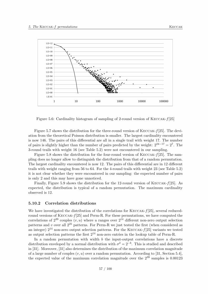
5. The Keccak-f permutations Keccak
1.E-01
1.E+00
1.E+01
1.E+02
1.E+03
1.E+04
1.E+05
1.E+06
1.E+07
1.E+08
1.E+09
1.E+10
1.E+11
1.E+12
1 10 100 1000 10000 100000
Figure 5.6: Cardinality histogram of sampling of 2-round version of Keccak-f [25]
Figure 5.7 shows the distribution for the three-round version of Keccak-f [25]. The devi-ation from the theoretical Poisson distribution is smaller. The largest cardinality encounteredis now 146. The pairs of this differential are all in a single trail with weight 17. The numberof pairs is slightly higher than the number of pairs predicted by the weight: 224−17 = 27. The3-round trails with weight 16 (see Table 5.2) were not encountered in our sampling.
Figure 5.8 shows the distribution for the four-round version of Keccak-f [25]. The sam-pling does no longer allow to distinguish the distribution from that of a random permutation.The largest cardinality encountered is now 12. The pairs of this differential are in 12 differenttrails with weight ranging from 56 to 64. For the 4-round trails with weight 23 (see Table 5.2)it is not clear whether they were encountered in our sampling: the expected number of pairsis only 2 and this may have gone unnoticed.
Finally, Figure 5.9 shows the distribution for the 12-round version of Keccak-f [25]. Asexpected, the distribution is typical of a random permutation. The maximum cardinalityobserved is 12.
5.10.2 Correlation distributions
We have investigated the distribution of the correlations for Keccak-f [25], several reduced-round versions of Keccak-f [25] and Perm-R. For these permutations, we have computed thecorrelations of 239 couples (v, u) where u ranges over 214 different non-zero output selectionpatterns and v over all 225 patterns. For Perm-R we just tested the first (when considered asan integer) 214 non-zero output selection patterns. For the Keccak-f [25] variants we testedas output selection patterns the first 214 non-zero entries in the lookup table of Perm-R.
In a random permutation with width b the input-output correlations have a discretedistribution enveloped by a normal distribution with �2 = 2−b. This is studied and describedin [31]. Moreover, [31] also determines the distribution of the maximum correlation magnitudeof a large number of couples (v, u) over a random permutation. According to [31, Section 5.4],the expected value of the maximum correlation magnitude over the 239 samples is 0.00123
57 / 100
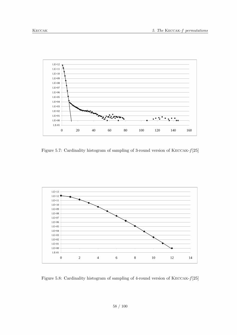
Keccak 5. The Keccak-f permutations
1.E-01
1.E+00
1.E+01
1.E+02
1.E+03
1.E+04
1.E+05
1.E+06
1.E+07
1.E+08
1.E+09
1.E+10
1.E+11
1.E+12
0 20 40 60 80 100 120 140 160
Figure 5.7: Cardinality histogram of sampling of 3-round version of Keccak-f [25]
1.E-01
1.E+00
1.E+01
1.E+02
1.E+03
1.E+04
1.E+05
1.E+06
1.E+07
1.E+08
1.E+09
1.E+10
1.E+11
1.E+12
1.E+13
0 2 4 6 8 10 12 14
Figure 5.8: Cardinality histogram of sampling of 4-round version of Keccak-f [25]
58 / 100
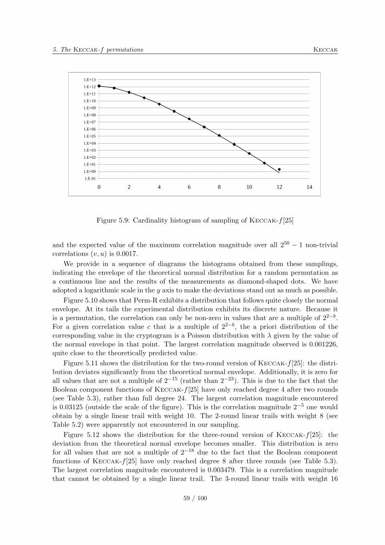
5. The Keccak-f permutations Keccak
1.E-01
1.E+00
1.E+01
1.E+02
1.E+03
1.E+04
1.E+05
1.E+06
1.E+07
1.E+08
1.E+09
1.E+10
1.E+11
1.E+12
1.E+13
0 2 4 6 8 10 12 14
Figure 5.9: Cardinality histogram of sampling of Keccak-f [25]
and the expected value of the maximum correlation magnitude over all 250 − 1 non-trivialcorrelations (v, u) is 0.0017.
We provide in a sequence of diagrams the histograms obtained from these samplings,indicating the envelope of the theoretical normal distribution for a random permutation asa continuous line and the results of the measurements as diamond-shaped dots. We haveadopted a logarithmic scale in the y axis to make the deviations stand out as much as possible.
Figure 5.10 shows that Perm-R exhibits a distribution that follows quite closely the normalenvelope. At its tails the experimental distribution exhibits its discrete nature. Because itis a permutation, the correlation can only be non-zero in values that are a multiple of 22−b.For a given correlation value c that is a multiple of 22−b, the a priori distribution of thecorresponding value in the cryptogram is a Poisson distribution with � given by the value ofthe normal envelope in that point. The largest correlation magnitude observed is 0.001226,quite close to the theoretically predicted value.
Figure 5.11 shows the distribution for the two-round version of Keccak-f [25]: the distri-bution deviates significantly from the theoretical normal envelope. Additionally, it is zero forall values that are not a multiple of 2−15 (rather than 2−23). This is due to the fact that theBoolean component functions of Keccak-f [25] have only reached degree 4 after two rounds(see Table 5.3), rather than full degree 24. The largest correlation magnitude encounteredis 0.03125 (outside the scale of the figure). This is the correlation magnitude 2−5 one wouldobtain by a single linear trail with weight 10. The 2-round linear trails with weight 8 (seeTable 5.2) were apparently not encountered in our sampling.
Figure 5.12 shows the distribution for the three-round version of Keccak-f [25]: thedeviation from the theoretical normal envelope becomes smaller. This distribution is zerofor all values that are not a multiple of 2−18 due to the fact that the Boolean componentfunctions of Keccak-f [25] have only reached degree 8 after three rounds (see Table 5.3).The largest correlation magnitude encountered is 0.003479. This is a correlation magnitudethat cannot be obtained by a single linear trail. The 3-round linear trails with weight 16
59 / 100
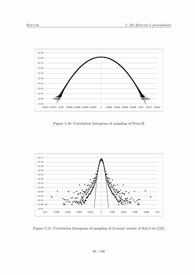
Keccak 5. The Keccak-f permutations
1.E-01
1.E+00
1.E+01
1.E+02
1.E+03
1.E+04
1.E+05
1.E+06
1.E+07
1.E+08
1.E+09
-0.0014 -0.0012 -0.001 -0.0008 -0.0006 -0.0004 -0.0002 0 0.0002 0.0004 0.0006 0.0008 0.001 0.0012 0.0014
Figure 5.10: Correlation histogram of sampling of Perm-R
1.E-01
1.E+00
1.E+01
1.E+02
1.E+03
1.E+04
1.E+05
1.E+06
1.E+07
1.E+08
1.E+09
1.E+10
1.E+11
-0.01 -0.008 -0.006 -0.004 -0.002 0 0.002 0.004 0.006 0.008 0.01
Figure 5.11: Correlation histogram of sampling of 2-round version of Keccak-f [25]
60 / 100
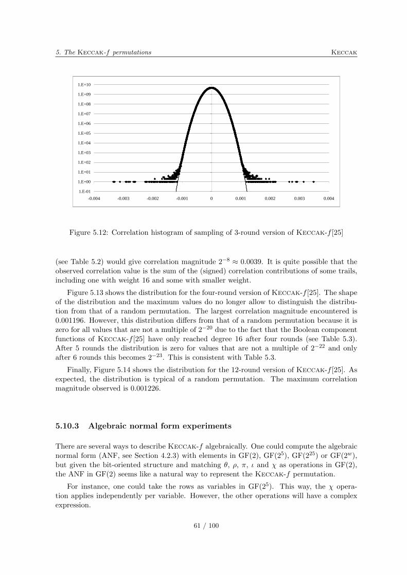
5. The Keccak-f permutations Keccak
1.E-01
1.E+00
1.E+01
1.E+02
1.E+03
1.E+04
1.E+05
1.E+06
1.E+07
1.E+08
1.E+09
1.E+10
-0.004 -0.003 -0.002 -0.001 0 0.001 0.002 0.003 0.004
Figure 5.12: Correlation histogram of sampling of 3-round version of Keccak-f [25]
(see Table 5.2) would give correlation magnitude 2−8 ≈ 0.0039. It is quite possible that theobserved correlation value is the sum of the (signed) correlation contributions of some trails,including one with weight 16 and some with smaller weight.
Figure 5.13 shows the distribution for the four-round version of Keccak-f [25]. The shapeof the distribution and the maximum values do no longer allow to distinguish the distribu-tion from that of a random permutation. The largest correlation magnitude encountered is0.001196. However, this distribution differs from that of a random permutation because it iszero for all values that are not a multiple of 2−20 due to the fact that the Boolean componentfunctions of Keccak-f [25] have only reached degree 16 after four rounds (see Table 5.3).After 5 rounds the distribution is zero for values that are not a multiple of 2−22 and onlyafter 6 rounds this becomes 2−23. This is consistent with Table 5.3.
Finally, Figure 5.14 shows the distribution for the 12-round version of Keccak-f [25]. Asexpected, the distribution is typical of a random permutation. The maximum correlationmagnitude observed is 0.001226.
5.10.3 Algebraic normal form experiments
There are several ways to describe Keccak-f algebraically. One could compute the algebraicnormal form (ANF, see Section 4.2.3) with elements in GF(2), GF(25), GF(225) or GF(2w),but given the bit-oriented structure and matching �, �, �, � and � as operations in GF(2),the ANF in GF(2) seems like a natural way to represent the Keccak-f permutation.
For instance, one could take the rows as variables in GF(25). This way, the � opera-tion applies independently per variable. However, the other operations will have a complexexpression.
61 / 100
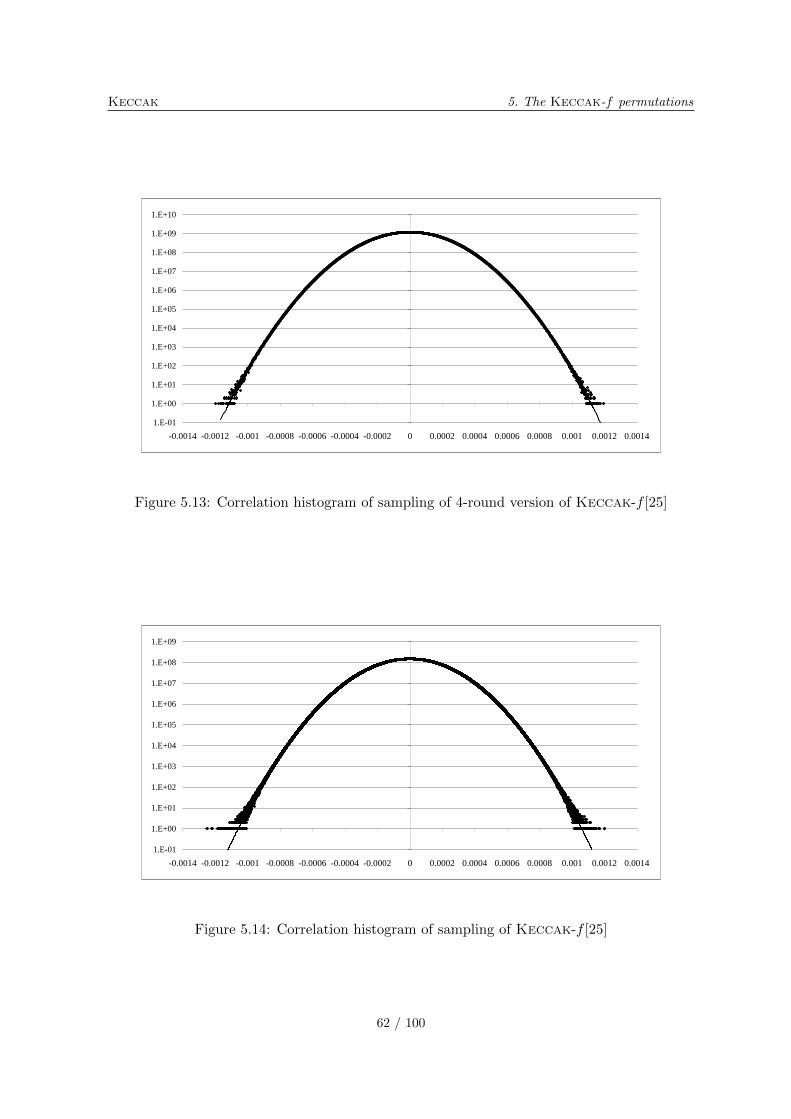
Keccak 5. The Keccak-f permutations
1.E-01
1.E+00
1.E+01
1.E+02
1.E+03
1.E+04
1.E+05
1.E+06
1.E+07
1.E+08
1.E+09
1.E+10
-0.0014 -0.0012 -0.001 -0.0008 -0.0006 -0.0004 -0.0002 0 0.0002 0.0004 0.0006 0.0008 0.001 0.0012 0.0014
Figure 5.13: Correlation histogram of sampling of 4-round version of Keccak-f [25]
1.E-01
1.E+00
1.E+01
1.E+02
1.E+03
1.E+04
1.E+05
1.E+06
1.E+07
1.E+08
1.E+09
-0.0014 -0.0012 -0.001 -0.0008 -0.0006 -0.0004 -0.0002 0 0.0002 0.0004 0.0006 0.0008 0.001 0.0012 0.0014
Figure 5.14: Correlation histogram of sampling of Keccak-f [25]
62 / 100
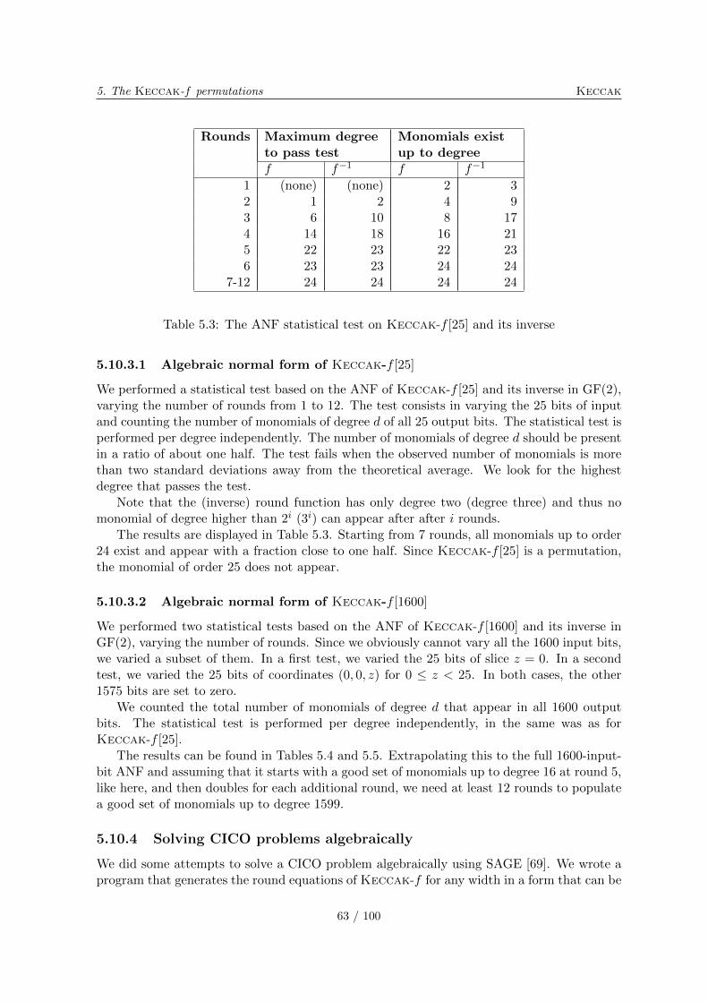
5. The Keccak-f permutations Keccak
Rounds Maximum degree Monomials existto pass test up to degreef f−1 f f−1
1 (none) (none) 2 32 1 2 4 93 6 10 8 174 14 18 16 215 22 23 22 236 23 23 24 24
7-12 24 24 24 24
Table 5.3: The ANF statistical test on Keccak-f [25] and its inverse
5.10.3.1 Algebraic normal form of Keccak-f [25]
We performed a statistical test based on the ANF of Keccak-f [25] and its inverse in GF(2),varying the number of rounds from 1 to 12. The test consists in varying the 25 bits of inputand counting the number of monomials of degree d of all 25 output bits. The statistical test isperformed per degree independently. The number of monomials of degree d should be presentin a ratio of about one half. The test fails when the observed number of monomials is morethan two standard deviations away from the theoretical average. We look for the highestdegree that passes the test.
Note that the (inverse) round function has only degree two (degree three) and thus nomonomial of degree higher than 2i (3i) can appear after after i rounds.
The results are displayed in Table 5.3. Starting from 7 rounds, all monomials up to order24 exist and appear with a fraction close to one half. Since Keccak-f [25] is a permutation,the monomial of order 25 does not appear.
5.10.3.2 Algebraic normal form of Keccak-f [1600]
We performed two statistical tests based on the ANF of Keccak-f [1600] and its inverse inGF(2), varying the number of rounds. Since we obviously cannot vary all the 1600 input bits,we varied a subset of them. In a first test, we varied the 25 bits of slice z = 0. In a secondtest, we varied the 25 bits of coordinates (0, 0, z) for 0 ≤ z < 25. In both cases, the other1575 bits are set to zero.
We counted the total number of monomials of degree d that appear in all 1600 outputbits. The statistical test is performed per degree independently, in the same was as forKeccak-f [25].
The results can be found in Tables 5.4 and 5.5. Extrapolating this to the full 1600-input-bit ANF and assuming that it starts with a good set of monomials up to degree 16 at round 5,like here, and then doubles for each additional round, we need at least 12 rounds to populatea good set of monomials up to degree 1599.
5.10.4 Solving CICO problems algebraically
We did some attempts to solve a CICO problem algebraically using SAGE [69]. We wrote aprogram that generates the round equations of Keccak-f for any width in a form that can be
63 / 100

Keccak 5. The Keccak-f permutations
Rounds Maximum degree Monomials existto pass test up to degreef f−1 f f−1
1 (none) (none) 2 32 (none) 3 3 93 (none) 10 5 174 5 25 9 255 16 25 17 25
6-24 25 25 25 25
Table 5.4: The ANF statistical test on Keccak-f [1600] and its inverse, varying slice z = 0
Rounds Maximum degree Monomials existto pass test up to degreef f−1 f f−1
1 (none) (none) 2 12 (none) 3 4 33 (none) 8 8 94 8 25 15 255 25 25 25 256 24 25 25 25
7-24 25 25 25 25
Table 5.5: The ANF statistical test on Keccak-f [1600] and its inverse, varying 25 bits oflane x = y = 0
64 / 100
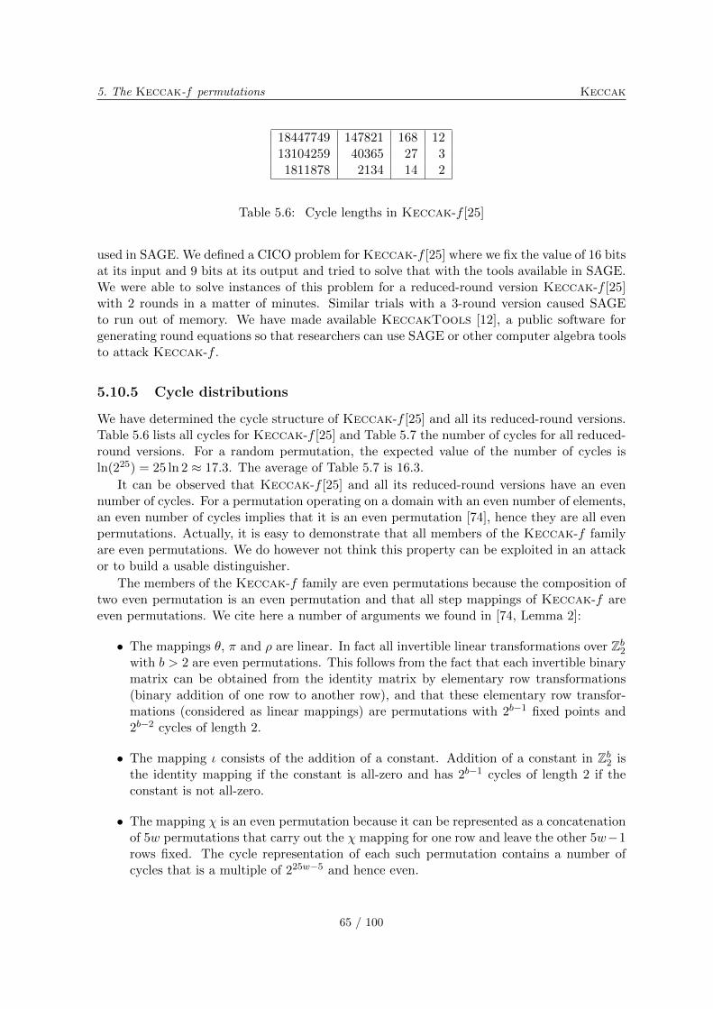
5. The Keccak-f permutations Keccak
18447749 147821 168 1213104259 40365 27 31811878 2134 14 2
Table 5.6: Cycle lengths in Keccak-f [25]
used in SAGE. We defined a CICO problem for Keccak-f [25] where we fix the value of 16 bitsat its input and 9 bits at its output and tried to solve that with the tools available in SAGE.We were able to solve instances of this problem for a reduced-round version Keccak-f [25]with 2 rounds in a matter of minutes. Similar trials with a 3-round version caused SAGEto run out of memory. We have made available KeccakTools [12], a public software forgenerating round equations so that researchers can use SAGE or other computer algebra toolsto attack Keccak-f .
5.10.5 Cycle distributions
We have determined the cycle structure of Keccak-f [25] and all its reduced-round versions.Table 5.6 lists all cycles for Keccak-f [25] and Table 5.7 the number of cycles for all reduced-round versions. For a random permutation, the expected value of the number of cycles isln(225) = 25 ln 2 ≈ 17.3. The average of Table 5.7 is 16.3.
It can be observed that Keccak-f [25] and all its reduced-round versions have an evennumber of cycles. For a permutation operating on a domain with an even number of elements,an even number of cycles implies that it is an even permutation [74], hence they are all evenpermutations. Actually, it is easy to demonstrate that all members of the Keccak-f familyare even permutations. We do however not think this property can be exploited in an attackor to build a usable distinguisher.
The members of the Keccak-f family are even permutations because the composition oftwo even permutation is an even permutation and that all step mappings of Keccak-f areeven permutations. We cite here a number of arguments we found in [74, Lemma 2]:
∙ The mappings �, � and � are linear. In fact all invertible linear transformations over ℤb2with b > 2 are even permutations. This follows from the fact that each invertible binarymatrix can be obtained from the identity matrix by elementary row transformations(binary addition of one row to another row), and that these elementary row transfor-mations (considered as linear mappings) are permutations with 2b−1 fixed points and2b−2 cycles of length 2.
∙ The mapping � consists of the addition of a constant. Addition of a constant in ℤb2 isthe identity mapping if the constant is all-zero and has 2b−1 cycles of length 2 if theconstant is not all-zero.
∙ The mapping � is an even permutation because it can be represented as a concatenationof 5w permutations that carry out the � mapping for one row and leave the other 5w−1rows fixed. The cycle representation of each such permutation contains a number ofcycles that is a multiple of 225w−5 and hence even.
65 / 100
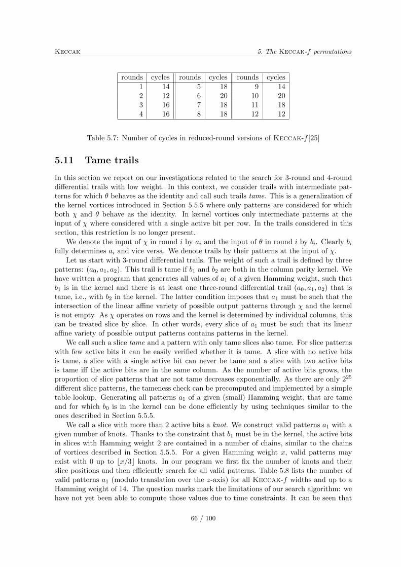
Keccak 5. The Keccak-f permutations
rounds cycles rounds cycles rounds cycles
1 14 5 18 9 142 12 6 20 10 203 16 7 18 11 184 16 8 18 12 12
Table 5.7: Number of cycles in reduced-round versions of Keccak-f [25]
5.11 Tame trails
In this section we report on our investigations related to the search for 3-round and 4-rounddifferential trails with low weight. In this context, we consider trails with intermediate pat-terns for which � behaves as the identity and call such trails tame. This is a generalization ofthe kernel vortices introduced in Section 5.5.5 where only patterns are considered for whichboth � and � behave as the identity. In kernel vortices only intermediate patterns at theinput of � where considered with a single active bit per row. In the trails considered in thissection, this restriction is no longer present.
We denote the input of � in round i by ai and the input of � in round i by bi. Clearly bifully determines ai and vice versa. We denote trails by their patterns at the input of �.
Let us start with 3-round differential trails. The weight of such a trail is defined by threepatterns: (a0, a1, a2). This trail is tame if b1 and b2 are both in the column parity kernel. Wehave written a program that generates all values of a1 of a given Hamming weight, such thatb1 is in the kernel and there is at least one three-round differential trail (a0, a1, a2) that istame, i.e., with b2 in the kernel. The latter condition imposes that a1 must be such that theintersection of the linear affine variety of possible output patterns through � and the kernelis not empty. As � operates on rows and the kernel is determined by individual columns, thiscan be treated slice by slice. In other words, every slice of a1 must be such that its linearaffine variety of possible output patterns contains patterns in the kernel.
We call such a slice tame and a pattern with only tame slices also tame. For slice patternswith few active bits it can be easily verified whether it is tame. A slice with no active bitsis tame, a slice with a single active bit can never be tame and a slice with two active bitsis tame iff the active bits are in the same column. As the number of active bits grows, theproportion of slice patterns that are not tame decreases exponentially. As there are only 225
different slice patterns, the tameness check can be precomputed and implemented by a simpletable-lookup. Generating all patterns a1 of a given (small) Hamming weight, that are tameand for which b0 is in the kernel can be done efficiently by using techniques similar to theones described in Section 5.5.5.
We call a slice with more than 2 active bits a knot. We construct valid patterns a1 with agiven number of knots. Thanks to the constraint that b1 must be in the kernel, the active bitsin slices with Hamming weight 2 are contained in a number of chains, similar to the chainsof vortices described in Section 5.5.5. For a given Hamming weight x, valid patterns mayexist with 0 up to ⌊x/3⌋ knots. In our program we first fix the number of knots and theirslice positions and then efficiently search for all valid patterns. Table 5.8 lists the number ofvalid patterns a1 (modulo translation over the z-axis) for all Keccak-f widths and up to aHamming weight of 14. The question marks mark the limitations of our search algorithm: wehave not yet been able to compute those values due to time constraints. It can be seen that
66 / 100
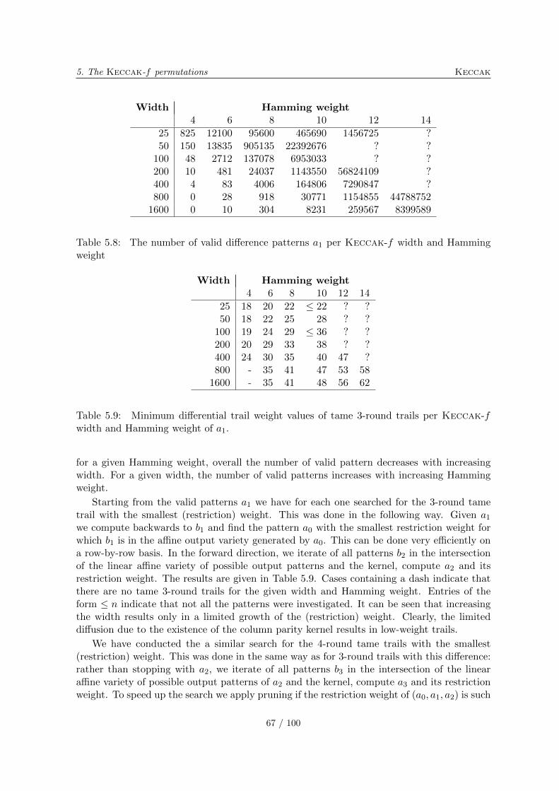
5. The Keccak-f permutations Keccak
Width Hamming weight4 6 8 10 12 14
25 825 12100 95600 465690 1456725 ?50 150 13835 905135 22392676 ? ?
100 48 2712 137078 6953033 ? ?200 10 481 24037 1143550 56824109 ?400 4 83 4006 164806 7290847 ?800 0 28 918 30771 1154855 44788752
1600 0 10 304 8231 259567 8399589
Table 5.8: The number of valid difference patterns a1 per Keccak-f width and Hammingweight
Width Hamming weight4 6 8 10 12 14
25 18 20 22 ≤ 22 ? ?50 18 22 25 28 ? ?
100 19 24 29 ≤ 36 ? ?200 20 29 33 38 ? ?400 24 30 35 40 47 ?800 - 35 41 47 53 58
1600 - 35 41 48 56 62
Table 5.9: Minimum differential trail weight values of tame 3-round trails per Keccak-fwidth and Hamming weight of a1.
for a given Hamming weight, overall the number of valid pattern decreases with increasingwidth. For a given width, the number of valid patterns increases with increasing Hammingweight.
Starting from the valid patterns a1 we have for each one searched for the 3-round tametrail with the smallest (restriction) weight. This was done in the following way. Given a1we compute backwards to b1 and find the pattern a0 with the smallest restriction weight forwhich b1 is in the affine output variety generated by a0. This can be done very efficiently ona row-by-row basis. In the forward direction, we iterate of all patterns b2 in the intersectionof the linear affine variety of possible output patterns and the kernel, compute a2 and itsrestriction weight. The results are given in Table 5.9. Cases containing a dash indicate thatthere are no tame 3-round trails for the given width and Hamming weight. Entries of theform ≤ n indicate that not all the patterns were investigated. It can be seen that increasingthe width results only in a limited growth of the (restriction) weight. Clearly, the limiteddiffusion due to the existence of the column parity kernel results in low-weight trails.
We have conducted the a similar search for the 4-round tame trails with the smallest(restriction) weight. This was done in the same way as for 3-round trails with this difference:rather than stopping with a2, we iterate of all patterns b3 in the intersection of the linearaffine variety of possible output patterns of a2 and the kernel, compute a3 and its restrictionweight. To speed up the search we apply pruning if the restriction weight of (a0, a1, a2) is such
67 / 100
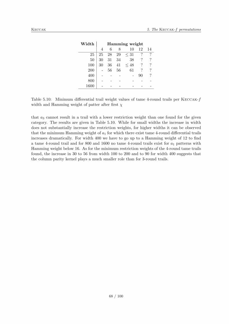
Keccak 5. The Keccak-f permutations
Width Hamming weight4 6 8 10 12 14
25 25 28 29 ≤ 31 ? ?50 30 31 34 38 ? ?
100 30 36 41 ≤ 48 ? ?200 - 56 56 61 ? ?400 - - - - 90 ?800 - - - - - -
1600 - - - - - -
Table 5.10: Minimum differential trail weight values of tame 4-round trails per Keccak-fwidth and Hamming weight of patter after first �
that a3 cannot result in a trail with a lower restriction weight than one found for the givencategory. The results are given in Table 5.10. While for small widths the increase in widthdoes not substantially increase the restriction weights, for higher widths it can be observedthat the minimum Hamming weight of a1 for which there exist tame 4-round differential trailsincreases dramatically. For width 400 we have to go up to a Hamming weight of 12 to finda tame 4-round trail and for 800 and 1600 no tame 4-round trails exist for a1 patterns withHamming weight below 16. As for the minimum restriction weights of the 4-round tame trailsfound, the increase in 30 to 56 from width 100 to 200 and to 90 for width 400 suggests thatthe column parity kernel plays a much smaller role than for 3-round trails.
68 / 100
Chapter 6
Usage
This chapter discusses the Keccak sponge functions from a users’ point of view.
6.1 Usage scenario’s for a sponge function
6.1.1 Random-oracle interface
A sponge function has the same input and output interface as a random oracle: It accepts anarbitrarily-long input message and produces an infinite output string that can be truncatedat the desired length. Unlike some other constructions, a sponge function does not have aso called initial value (IV) that can be used as an additional input. Instead, any additionalinput, such as a key or a diversifier, can be prepended to the input message, as one would dowith a random oracle. See also Section 6.3 for a related discussion.
6.1.2 Linking to the security claim
Basically, the security claim in [11, Section 3] specifies that any attacks on a member of theKeccak family should have a complexity of order 2c/2 calls to Keccak-f , unless easier on arandom oracle.
For the first four Keccak candidates with fixed digest length, the output length n satisfiesn = c/2. This means that using Keccak as a hash function provides collision resistance of2n/2, (second) preimage resistance of 2n and resistance to length-extension. Furthermore, forany fixed subset of m < n output bits, the same complexities apply with m replacing n.
For the fifth candidate Keccak[] with its arbitrarily-long output mode, the idea is prettymuch the same, except that, for any attacks that would require more than 2c/2 = 2288 on arandom oracle, the attack may work on Keccak[] with a complexity of 2c/2 = 2288.
With a random oracle, one can construct a pseudo-random function (PRF) Fk(m) byprepending the message m with a key k, i.e., Fk(m) = ℛO(k∣∣m). In such a case, thefunction behaves as a random function to anyone not knowing the key k but having access tothe same random oracle (see also Section 3.1.5). As a consequence of the security claim, thesame construction can be used with a Keccak sponge function and the same security can beexpected when the adversary does not have access to a complexity of order higher than 2c/2.
69 / 100
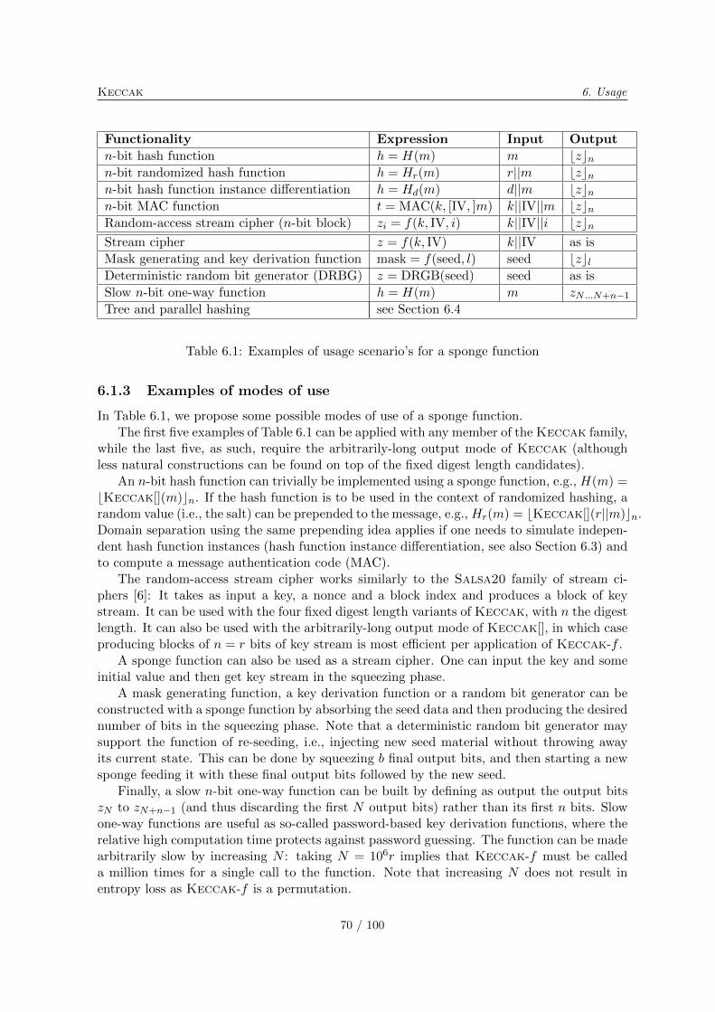
Keccak 6. Usage
Functionality Expression Input Output
n-bit hash function ℎ = H(m) m ⌊z⌋nn-bit randomized hash function ℎ = Hr(m) r∣∣m ⌊z⌋nn-bit hash function instance differentiation ℎ = Hd(m) d∣∣m ⌊z⌋nn-bit MAC function t = MAC(k, [IV, ]m) k∣∣IV∣∣m ⌊z⌋nRandom-access stream cipher (n-bit block) zi = f(k, IV, i) k∣∣IV∣∣i ⌊z⌋nStream cipher z = f(k, IV) k∣∣IV as is
Mask generating and key derivation function mask = f(seed, l) seed ⌊z⌋lDeterministic random bit generator (DRBG) z = DRGB(seed) seed as is
Slow n-bit one-way function ℎ = H(m) m zN...N+n−1Tree and parallel hashing see Section 6.4
Table 6.1: Examples of usage scenario’s for a sponge function
6.1.3 Examples of modes of use
In Table 6.1, we propose some possible modes of use of a sponge function.The first five examples of Table 6.1 can be applied with any member of the Keccak family,
while the last five, as such, require the arbitrarily-long output mode of Keccak (althoughless natural constructions can be found on top of the fixed digest length candidates).
An n-bit hash function can trivially be implemented using a sponge function, e.g., H(m) =⌊Keccak[](m)⌋n. If the hash function is to be used in the context of randomized hashing, arandom value (i.e., the salt) can be prepended to the message, e.g., Hr(m) = ⌊Keccak[](r∣∣m)⌋n.Domain separation using the same prepending idea applies if one needs to simulate indepen-dent hash function instances (hash function instance differentiation, see also Section 6.3) andto compute a message authentication code (MAC).
The random-access stream cipher works similarly to the Salsa20 family of stream ci-phers [6]: It takes as input a key, a nonce and a block index and produces a block of keystream. It can be used with the four fixed digest length variants of Keccak, with n the digestlength. It can also be used with the arbitrarily-long output mode of Keccak[], in which caseproducing blocks of n = r bits of key stream is most efficient per application of Keccak-f .
A sponge function can also be used as a stream cipher. One can input the key and someinitial value and then get key stream in the squeezing phase.
A mask generating function, a key derivation function or a random bit generator can beconstructed with a sponge function by absorbing the seed data and then producing the desirednumber of bits in the squeezing phase. Note that a deterministic random bit generator maysupport the function of re-seeding, i.e., injecting new seed material without throwing awayits current state. This can be done by squeezing b final output bits, and then starting a newsponge feeding it with these final output bits followed by the new seed.
Finally, a slow n-bit one-way function can be built by defining as output the output bitszN to zN+n−1 (and thus discarding the first N output bits) rather than its first n bits. Slowone-way functions are useful as so-called password-based key derivation functions, where therelative high computation time protects against password guessing. The function can be madearbitrarily slow by increasing N : taking N = 106r implies that Keccak-f must be calleda million times for a single call to the function. Note that increasing N does not result inentropy loss as Keccak-f is a permutation.
70 / 100
6. Usage Keccak
6.2 Backward compatibility with old standards
6.2.1 Input block length and output length
Several standards that make use of a hash function assume it has an input block length and afixed output length. A sponge function supports inputs of any length and returns an outputof arbitrary length. When a sponge function is used in those cases, an input block length andan output length must be chosen. We distinguish two cases.
∙ For the four SHA-3 candidates where the digest length is fixed, the input block length isassumed to be the bitrate r and the output length is the digest length of the candidaten ∈ {224, 256, 384, 512}.
∙ For the fifth SHA-3 candidate Keccak[], the output length n must be explicitly chosento fit a particular standard. Since the input block length is usually assumed to begreater than or equal to the output length, the input block length can be taken as aninteger multiple of the bitrate, mr, to satisfy this constraint.
6.2.2 Initial value
Some constructions that make use of hash functions assume the existence of a so-called initialvalue (IV) and use this as additional input. In the sponge construction the root state couldbe considered as such an IV. However, for the security of the sponge construction it is crucialthat the root state is fixed and cannot be manipulated by the adversary. If Keccak spongefunctions are used in constructions that require it to have an initial value as supplementaryinput, e.g., as in NMAC [5], this initial value shall just be pre-pended to the regular input.
6.2.3 HMAC
HMAC [5, 62] is fully specified in terms of a hash function, so it can be applied as such usingone of the Keccak candidates. It is parameterized by an input block length and an outputlength, which we propose to choose as in Section 6.2.1 above.
Apart from length extension attacks, the security of HMAC comes essentially from thesecurity of its inner hash. The inner hash is obtained by prepending the message with thekey, which gives a secure MAC. The outer hash prepends the inner MAC with the key (butpadded differently), so again giving a secure MAC. (Of course, it is also possible to use thegeneric MAC construction given in Section 6.1, which requires only one application of thesponge function.)
From the security claim in [11, Section 3], a PRF constructed using HMAC shall re-sist a distinguishing attack that requires much fewer than 2c/2 queries and significantly lesscomputation than a preimage attack.
6.2.4 NIST and other relevant standards
The following standards are based either generically on a hash function or on HMAC. Inall cases, at least one of the Keccak candidates can readily be used as the required hashfunction or via HMAC.
71 / 100
Keccak 6. Usage
∙ IEEE P1393 [40] requires a hash function for a key derivation function (X9.42) and amask generating function (MGF-hash). (Note that the MGF-hash construction couldbe advantageously replaced by the arbitrarily-long output mode of Keccak[].)
∙ PKCS #1 [50] also requires a hash function for a mask generating function (MGF1).
∙ The key derivation functions in NIST SP 800-108 [63] rely on HMAC.
∙ The key derivation functions in NIST SP 800-56a [59] are generically based on a hashfunction.
∙ The digital signature standard (DSS) [56] makes use of a hash function with outputsize of 160, 224 or 256 bits. Output truncation is permitted so any of the five Keccakcandidates can be chosen to produce the 160 bits of output.
∙ In the randomized hashing digital signatures of NIST SP 800-106 [58], the message israndomized prior to hashing, so this is independent of the hash function used. (With asponge function, this can also be done by prepending the random value to the message.)
∙ The deterministic random bit generation (DRBG) in NIST SP 800-90 [60] is basedon either a hash function or on HMAC. (Maybe the arbitrarily-long output mode ofKeccak[] could be used for such an application.)
6.3 Input formatting and diversification
In a sponge function, the input is like a white page: It does not impose any specific structureto it. Some SHA-3 submissions (e.g., Skein [33]) propose a structured way to add optionalinputs (e.g., key, nonce, personalization data) in addition to the main input message.
For Keccak, we do not wish to impose a way data would be structured. We prefer tokeep the input as a white page and let anyone build upon it. Instead, we propose in thissection a simple convention that allows anyone to impose his/her own format. Note that thisconvention could be used with any other hash function.
In the Keccak specifications [11], out of the 256 possible values for the diversifier d only5 have been assigned. There are thus many available values of d to create diversified spongefunctions, but clearly not enough for anyone to choose his/her own.
The idea is to prefix the input with a namespace name. The owner of the namespace canthen define the format of any input data, appended to the namespace name. To make thisconstruction distinct from the five candidates defined in [11], we propose to assign d = 1 inthis case, for any valid r. More specifically, we propose the namespace name to be a uniformresource identifier (URI) [36], similarly to what is done for XML [72]. The namespace nameis encoded in UTF-8 [35] as a sequence of bytes, followed by the byte 08:
KeccakNS[r, c,ns](data) ≜ Keccak[r, c, d = 1](UTF8(ns)∣∣08∣∣ encodens(data)),
where encodens is a function defined by the owner of the namespace ns. This allows domainseparation: Two inputs, formatted using different namespaced conventions, will thus alwaysbe different.
For efficiency reasons, the namespace owner may design encodens to put fixed bytes afterthe encoded namespace name and before the variable data, so as to create a constant prefix
72 / 100
6. Usage Keccak
of r bits (or a multiple of r bits). This way, the state obtained after absorbing the constantprefix can be precomputed once for all.
Using a specific namespace also implies how the output of the sponge function is used. Inthe Keccak specifications [11], the four fixed output length candidates are diversified usingd. Here we propose an additional possibility, where the namespace owner can decide whatis the output length, if not arbitrarily long, or in which way the desired output length isencoded.
6.4 Parallel and tree hashing
Tree hashing (see, e.g., [54, 65]) can be used to speed up the computation of a hash functionby taking advantage of parallelism in modern architectures. It can be performed on top ofmany hash function constructions, including sponge functions. In this section, we propose atree hashing scheme, called KeccakTree, which explicitly uses Keccak but which couldalso be implemented on top of another hash function. In addition, this scheme can be seenas an example of an application of sponge functions. It does not exclude variants or otherapplications: By basing KeccakTree on KeccakNS, other tree hashing schemes can bedefined using different namespaces.
In a nutshell, the construction works as follows. Consider a rooted tree, with internalnodes and leaves. The input message is cut into blocks, which are spread onto the leaves.Each leaf is then hashed, producing I bits of output, for a given value I. An internal nodegathers the output values of its (ordered) sons, concatenates them and hashes them. Thisprocess is repeated recursively until the root node is reached. The output of the root node,also called final node, can be arbitrarily long.
Since the input message is arbitrarily long and a priori unknown, we have to define howthe tree can grow or how a finite tree can accept a growing number of input blocks. In fact,we propose two options.
∙ The first option is final node growing (FNG). The degree of the final node grows as afunction of the input message length, and the number of leaves then increases propor-tionally.
∙ The second option is leaf interleaving (LI), where the tree size and the number of leavesare fixed, but the message input blocks are interleaved onto the leaves.
For randomized and keyed hashing, it should be possible to prefix all the node inputs withthe salt or key. To this purpose, the construction accepts such a prefix.
6.4.1 Definitions
The input of the scheme are two binary strings: the prefix (key or salt) P (from 0 to 2040bits) and the input message M . Its tree parameters, collectively denoted A, are the following:
∙ the tree growing mode G ∈ {LI,FNG};
∙ the height H of the tree;
∙ the degree D of the nodes;
73 / 100
Keccak 6. Usage
∙ the leaf block size B.
When G = LI, the tree is a balanced rooted tree of height H. All the internal nodes havedegree D. When G = FNG, the final node has variable degree (as a function of the inputmessage length) and all other internal nodes have degree D.
For all nodes, the scheme uses the sponge function defined by
K[r, c] ≜ KeccakNS[r, c,ns = “http://keccak.noekeon.org/tree/”].
Its input is composed of the prefix P , a partial input message m ∈ {0, 1}∗, a flag v ∈{final,nonfinal} and the scheme parameters A when v = final:
K[r, c](P,m, nonfinal) or K[r, c](P,m, final, A).
For simplicity, we omit the fixed parameters r and c in the sequel. The input argumentsare encoded into a binary string according to Algorithm 6. The prefix length ∣P ∣ must bean integral number of bytes and such that ∣P ∣/8 ∈ [0 . . . 255]. The possible values of A areconstrained by H,D ∈ [0 . . . 255], B is a multiple of 8 bits and B/8 ∈ [1 . . . 216 − 1]. Inaddition, H ≥ 1 when G = FNG.
Algorithm 6 encodehttp://keccak.noekeon.org/tree/(P,m, v,A)
Input P,m, v,ALet M = enc(∣P ∣/8, 8)∣∣PLet l = ∣UTF8(http://keccak.noekeon.org/tree/)∣+ 8 + ∣M ∣ = 264 + ∣P ∣Align M to a block boundary: M = M ∣∣0(−l) mod r
M = M ∣∣pad(m, 8)if v = final thenM = M ∣∣(enc(0, 8) if G = LI, or enc(1, 8) if G = FNG)M = M ∣∣enc(H, 8)∣∣enc(D, 8)∣∣enc(B/8, 16)M = M ∣∣enc(1, 8)
elseM = M ∣∣enc(0, 8)
end ifreturn M
We then define how the data are divided into leaves. The number L of leaves depends on
the tree growing mode G. If G = LI, L = DH . If G = FNG, L = RDH−1 with R =⌈∣M ∣
BDH−1
⌉.
Input message blocks are assigned to the leaves according to Algorithm 7.
Algorithm 7 Construction of the leaves
For each leaf Lj , 0 ≤ j ≤ L− 1, set Lj to the empty stringfor i = 0 to ∣M ∣ − 1 doj =
⌊iB
⌋mod L
Append bit i of M to Ljend for
The processing at each node is defined in Algorithm 8. The output of the KeccakTreescheme is the output of the final node obtained by calling Node(0, 0).
74 / 100
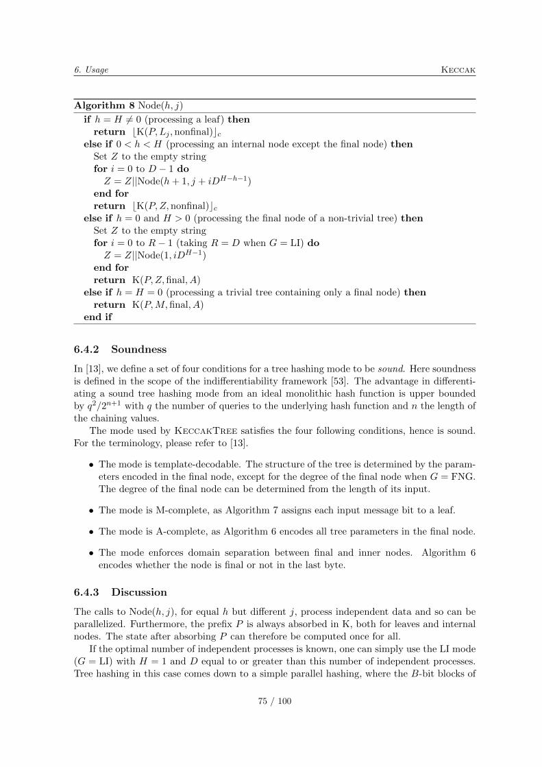
6. Usage Keccak
Algorithm 8 Node(ℎ, j)
if ℎ = H ∕= 0 (processing a leaf) thenreturn ⌊K(P,Lj ,nonfinal)⌋c
else if 0 < ℎ < H (processing an internal node except the final node) thenSet Z to the empty stringfor i = 0 to D − 1 doZ = Z∣∣Node(ℎ+ 1, j + iDH−ℎ−1)
end forreturn ⌊K(P,Z, nonfinal)⌋c
else if ℎ = 0 and H > 0 (processing the final node of a non-trivial tree) thenSet Z to the empty stringfor i = 0 to R− 1 (taking R = D when G = LI) doZ = Z∣∣Node(1, iDH−1)
end forreturn K(P,Z, final, A)
else if ℎ = H = 0 (processing a trivial tree containing only a final node) thenreturn K(P,M,final, A)
end if
6.4.2 Soundness
In [13], we define a set of four conditions for a tree hashing mode to be sound. Here soundnessis defined in the scope of the indifferentiability framework [53]. The advantage in differenti-ating a sound tree hashing mode from an ideal monolithic hash function is upper boundedby q2/2n+1 with q the number of queries to the underlying hash function and n the length ofthe chaining values.
The mode used by KeccakTree satisfies the four following conditions, hence is sound.For the terminology, please refer to [13].
∙ The mode is template-decodable. The structure of the tree is determined by the param-eters encoded in the final node, except for the degree of the final node when G = FNG.The degree of the final node can be determined from the length of its input.
∙ The mode is M-complete, as Algorithm 7 assigns each input message bit to a leaf.
∙ The mode is A-complete, as Algorithm 6 encodes all tree parameters in the final node.
∙ The mode enforces domain separation between final and inner nodes. Algorithm 6encodes whether the node is final or not in the last byte.
6.4.3 Discussion
The calls to Node(ℎ, j), for equal ℎ but different j, process independent data and so can beparallelized. Furthermore, the prefix P is always absorbed in K, both for leaves and internalnodes. The state after absorbing P can therefore be computed once for all.
If the optimal number of independent processes is known, one can simply use the LI mode(G = LI) with H = 1 and D equal to or greater than this number of independent processes.Tree hashing in this case comes down to a simple parallel hashing, where the B-bit blocks of
75 / 100
Keccak 6. Usage
the input message are equally spread onto D different sponge functions. The D results arethen combined at the final node to make the final output string. (The performance of such aconfiguration is discussed in Section 7.3.3.)
In addition to the LI and FNG growing modes, one can make the tree grow by increasingits height H until the number of leaves L is large enough for ∣M ∣. Setting G = LI in thiscase does not really interleave the input blocks, but fixes the tree. Knowing whether a nodeis going to be the final node (if H is large enough) or not becomes significant only at the endof the absorbing phase of K. Once H is large enough, the implementation can then fix it andmark the candidate final node as final.
From the soundness of the construction, the expected workload for differentiating thisscheme from a random oracle is of the order 2n/2 with n the output size of the called com-pression function (i.e., in this case K with n = c). For this reason, this scheme would besub-optimal if used with one of the four fixed-output length candidates of [11, Section 4] asthey all have an output size n that satisfies n = c/2. When using as underlying compressionfunction a function that is claimed to be indifferentiable with a capacity c, the optimum out-put size to use is also c, resulting in the absence of generic attacks with expected workloadof order below 2c/2.
76 / 100
Chapter 7
Implementation
In this chapter, we discuss the implementation of Keccak in software and in hardware,together with its estimated performances.
7.1 Bit and byte numbering conventions
As it impacts the reference implementation, the bit and byte numbering conventions aredefined in [11, Section 5.1]. In this section, we wish to detail our choices concerning themapping between the bits of the Keccak-f [b] permutation and their representation in termsof w-bit CPU words and in the SHA-3 API defined by NIST [61].
As explained in [11, Section 1], the bits in the state are numbered from 0 to b− 1, and biti = z+w(5y+x) corresponds to the coordinates (x, y, z). From the software implementationpoint of view, we expect the bits in a lane (i.e., with the same coordinates (x, y)) to be packedtogether in a w-bit CPU word, so that, if the processor allows it, the operation � becomes aset of CPU word rotations.
For the � operation to be translated into rotation instructions in the processor, the num-bering z must be either an increasing or a decreasing function of the bit numbering in theprocessor’s conventions. So, up to a constant offset, either z = 0 is the most significant bit(MSB) and z = w − 1 is the least significant bit (LSB), or vice-versa.
The input bits of the hash function come through the Update function of the API, orga-nized as a sequence of bytes. Within each block, the message bit i = ibit + 8ibyte is going tobe XORed with the state bit i. To avoid re-ordering bits or bytes and to allow a word-wiseXORing, the message bit numbering should follow the same convention as the state bit num-bering. In particular, if z = 0 indicates the MSB (resp. LSB), ibyte = 0 should indicate themost (resp. least) significant byte within a word.
Since the NIST reference platform follows the little-endian (LE) convention, we adopt thefollowing numbering of bits and bytes: when mapping a lane to a CPU word, bit z = 0 isthe LSB. Within a CPU word, the byte ibyte = 0 is the least significant byte. Within a byte,ibit = 0 is the LSB. This way, the message bits can be organized as a sequence of words(except for the last bits), to be XORed directly to the lanes of the state on a LE processor.
The convention in the Update function is different, and this is the reason for applying theformal bit reordering of [11, Section 5.1]. It formalizes the chosen translation between the twoconventions, while having an extremely limited impact on the implementation. In practice,only the bits of the last byte (when incomplete) of the input message need to be shifted.
77 / 100
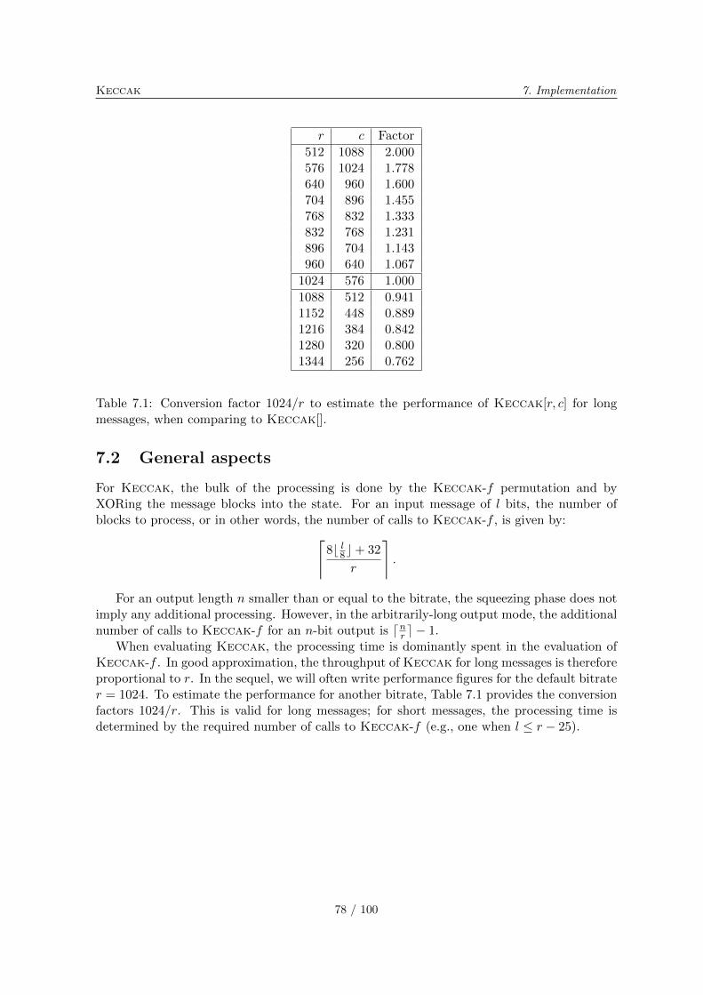
Keccak 7. Implementation
r c Factor
512 1088 2.000576 1024 1.778640 960 1.600704 896 1.455768 832 1.333832 768 1.231896 704 1.143960 640 1.067
1024 576 1.000
1088 512 0.9411152 448 0.8891216 384 0.8421280 320 0.8001344 256 0.762
Table 7.1: Conversion factor 1024/r to estimate the performance of Keccak[r, c] for longmessages, when comparing to Keccak[].
7.2 General aspects
For Keccak, the bulk of the processing is done by the Keccak-f permutation and byXORing the message blocks into the state. For an input message of l bits, the number ofblocks to process, or in other words, the number of calls to Keccak-f , is given by:⌈
8⌊ l8⌋+ 32
r
⌉.
For an output length n smaller than or equal to the bitrate, the squeezing phase does notimply any additional processing. However, in the arbitrarily-long output mode, the additionalnumber of calls to Keccak-f for an n-bit output is ⌈nr ⌉ − 1.
When evaluating Keccak, the processing time is dominantly spent in the evaluation ofKeccak-f . In good approximation, the throughput of Keccak for long messages is thereforeproportional to r. In the sequel, we will often write performance figures for the default bitrater = 1024. To estimate the performance for another bitrate, Table 7.1 provides the conversionfactors 1024/r. This is valid for long messages; for short messages, the processing time isdetermined by the required number of calls to Keccak-f (e.g., one when l ≤ r − 25).
78 / 100
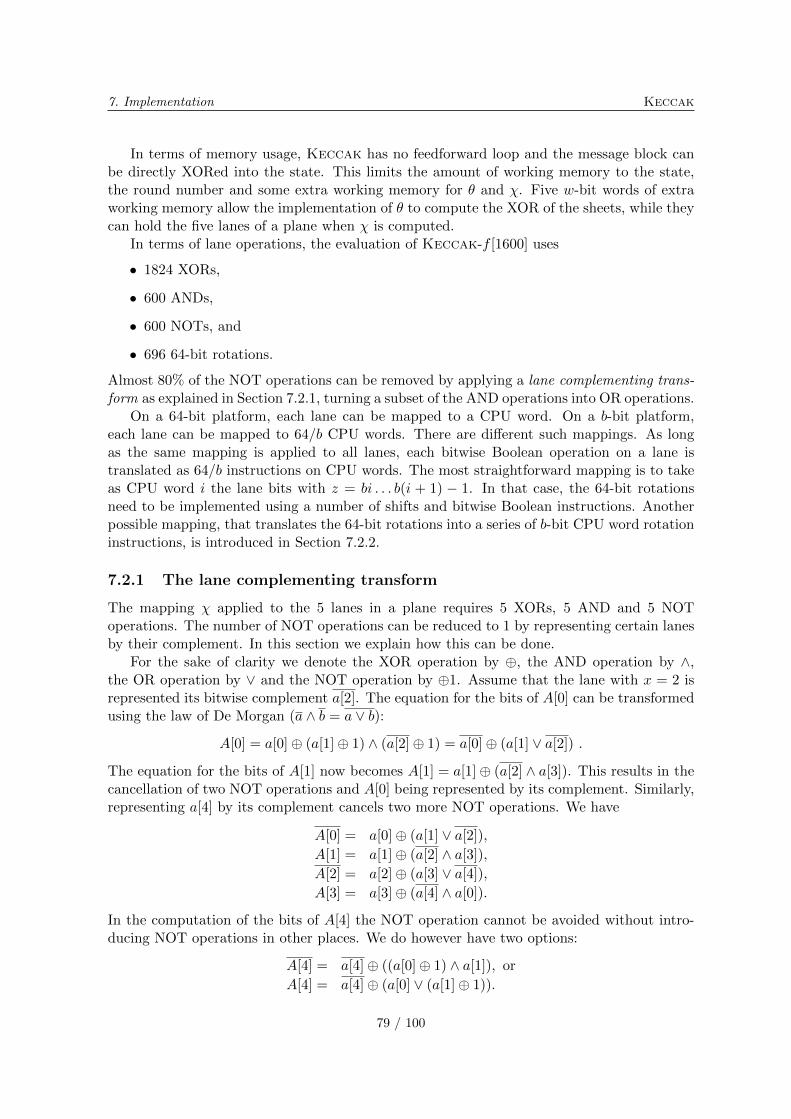
7. Implementation Keccak
In terms of memory usage, Keccak has no feedforward loop and the message block canbe directly XORed into the state. This limits the amount of working memory to the state,the round number and some extra working memory for � and �. Five w-bit words of extraworking memory allow the implementation of � to compute the XOR of the sheets, while theycan hold the five lanes of a plane when � is computed.
In terms of lane operations, the evaluation of Keccak-f [1600] uses
∙ 1824 XORs,
∙ 600 ANDs,
∙ 600 NOTs, and
∙ 696 64-bit rotations.
Almost 80% of the NOT operations can be removed by applying a lane complementing trans-form as explained in Section 7.2.1, turning a subset of the AND operations into OR operations.
On a 64-bit platform, each lane can be mapped to a CPU word. On a b-bit platform,each lane can be mapped to 64/b CPU words. There are different such mappings. As longas the same mapping is applied to all lanes, each bitwise Boolean operation on a lane istranslated as 64/b instructions on CPU words. The most straightforward mapping is to takeas CPU word i the lane bits with z = bi . . . b(i + 1) − 1. In that case, the 64-bit rotationsneed to be implemented using a number of shifts and bitwise Boolean instructions. Anotherpossible mapping, that translates the 64-bit rotations into a series of b-bit CPU word rotationinstructions, is introduced in Section 7.2.2.
7.2.1 The lane complementing transform
The mapping � applied to the 5 lanes in a plane requires 5 XORs, 5 AND and 5 NOToperations. The number of NOT operations can be reduced to 1 by representing certain lanesby their complement. In this section we explain how this can be done.
For the sake of clarity we denote the XOR operation by ⊕, the AND operation by ∧,the OR operation by ∨ and the NOT operation by ⊕1. Assume that the lane with x = 2 isrepresented its bitwise complement a[2]. The equation for the bits of A[0] can be transformedusing the law of De Morgan (a ∧ b = a ∨ b):
A[0] = a[0]⊕ (a[1]⊕ 1) ∧ (a[2]⊕ 1) = a[0]⊕ (a[1] ∨ a[2]) .
The equation for the bits of A[1] now becomes A[1] = a[1]⊕ (a[2] ∧ a[3]). This results in thecancellation of two NOT operations and A[0] being represented by its complement. Similarly,representing a[4] by its complement cancels two more NOT operations. We have
A[0] = a[0]⊕ (a[1] ∨ a[2]),
A[1] = a[1]⊕ (a[2] ∧ a[3]),
A[2] = a[2]⊕ (a[3] ∨ a[4]),
A[3] = a[3]⊕ (a[4] ∧ a[0]).
In the computation of the bits of A[4] the NOT operation cannot be avoided without intro-ducing NOT operations in other places. We do however have two options:
A[4] = a[4]⊕ ((a[0]⊕ 1) ∧ a[1]), or
A[4] = a[4]⊕ (a[0] ∨ (a[1]⊕ 1)).
79 / 100
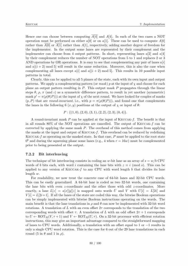
Keccak 7. Implementation
Hence one can choose between computing A[4] and A[4]. In each of the two cases a NOToperation must be performed on either a[0] or on a[1]. These can be used to compute A[0]rather than A[0] or A[1] rather than A[1], respectively, adding another degree of freedom forthe implementer. In the output some lanes are represented by their complement and theimplementer can choose from 4 output patterns. In short, representing lanes a[2] and a[4]by their complement reduces the number of NOT operations from 5 to 1 and replaces 2 or 3AND operations by OR operations. It is easy to see that complementing any pair of lanes a[i]and a[(i + 2) mod 5] will result in the same reduction. Moreover, this is also the case whencomplementing all lanes except a[i] and a[(i + 2) mod 5]. This results in 10 possible inputpatterns in total.
Clearly, this can be applied to all 5 planes of the state, each with its own input and outputpatterns. We apply a complementing pattern (or mask) p at the input of � and choose for eachplane an output pattern resulting in P . This output mask P propagates through the linearsteps �, �, � (and �) as a symmetric difference pattern, to result in yet another (symmetric)mask p′ = �(�(�(P ))) at the input of � of the next round. We have looked for couples of masks(p, P ) that are round-invariant, i.e., with p = �(�(�(P ))), and found one that complementsthe lanes in the following 6 (x, y) positions at the output of � or input of �:
P : {(1, 0), (2, 0), (3, 1), (2, 2), (2, 3), (0, 4)}.
A round-invariant mask P can be applied at the input of Keccak-f . The benefit is thatin all rounds 80% of the NOT operations are cancelled. The output of Keccak-f can becorrected by applying the same mask P . The overhead of this method comes from applyingthe masks at the input and output of Keccak-f . This overhead can be reduced by redefiningKeccak-f as operating on the masked state. In that case, P must be applied to the root state0b and during the squeezing phase some lanes (e.g., 4 when r = 16w) must be complementedprior to being presented at the output.
7.2.2 Bit interleaving
The technique of bit interleaving consists in coding an w-bit lane as an array of s = w/b CPUwords of b bits each, with word i containing the lane bits with z ≡ i (mod s). This can beapplied to any version of Keccak-f to any CPU with word length b that divides its lanelength w.
For readability, we now treat the concrete case of 64-bit lanes and 32-bit CPU words.This can be easily generalized. A 64-bit lane is coded as two 32-bit words, one containingthe lane bits with even z-coordinate and the other those with odd z-coordinates. Moreexactly, a lane L[z] = a[x][y][z] is mapped onto words U and V with U [i] = L[2i] andV [i] = L[2i+1]. If all the lanes of the state are coded this way, the bitwise Boolean operationscan be simply implemented with bitwise Boolean instructions operating on the words. Themain benefit is that the lane translations in � and � can now be implemented with 32-bit wordrotations. A translation of L with an even offset 2� corresponds to the translation of the twocorresponding words with offset � . A translation of L with an odd offset 2� + 1 correspondsto U ← ROT32(V, � + 1) and V ← ROT32(U, �). On a 32-bit processor with efficient rotationinstructions, this may give an important advantage compared to the straightforward mappingof lanes to CPU words. Additionally, a translation with an offset equal to 1 or −1 results inonly a single CPU word rotation. This is the case for 6 out of the 29 lane translations in eachround (5 in � and 1 in �).
80 / 100

7. Implementation Keccak
The bit-interleaving representation can be used in all of Keccak-f where the input andoutput of Keccak-f assume this representation. This implies that during the absorbing theinput blocks must be presented in bit-interleaving representation and during the squeezingthe output blocks are made available in bit-interleaving representation. When implementingKeccak in strict compliance to the specifications [11], the input blocks must be transformedto the bit-interleaving representation and the output blocks must be transformed back tothe standard representation. However, one can imagine applications that require a securehash function but no interoperability with respect to the exact coding. In that case one maypresent the input in interleaved form and use the output in this form too. The resultingfunction will only differ from Keccak by the order of bits in its input and output.
In hashing applications, the output is usually kept short and some overhead is caused byapplying the bit-interleaving transform to the input. Such a transform can be implementedusing shifts and bitwise operations. For implementing Keccak-f [1600] on a 32-bit CPU, wemust distribute the 64 bits of a lane to two 32-bit words. The cost of this transform is about2 cycles/byte on the reference platform (see Table 7.3). On some platforms, look-up tablescan speed up this process, although the gain is not always significant.
7.3 Software implementation
We provide a reference and two optimized implementations of the Keccak candidates inANSI C. The file KeccakSponge.c is common to the three flavors and implements the NISTAPI, including the functions Init, Update, Final and Hash, plus the additional functionSqueeze (see [11, Section 5.2]).
The reference implementation calls the Keccak-f [1600] permutation written in Keccak-
PermutationReference.c, while the optimized versions use KeccakPermutationOptimized-32.c and KeccakPermutationOptimized64.c for 32-bit and 64-bit platforms respectively.
For best performance, we allow the state to be stored in an opaque way during the hashcomputation. In particular, the state can have some of its lanes complemented (as in 7.2.1),the even and odd bits separated (as in 7.2.2) or the bytes in a word reordered according tothe endianness of the machine. The methods that apply on the state are:
∙ KeccakInitializeState() to set the state to zero;
∙ KeccakPermutation() to apply the Keccak-f [1600] permutation on it;
∙ KeccakAbsorb1024bits() and KeccakAbsorb() to XOR the input, given as bytes, tothe state and then apply the permutation;
∙ KeccakExtract1024bits() and KeccakExtract() to extract output bits from the statein the squeezing phase.
In the case of the reference implementation, separate functions are provided for the �, �,�, � and � operations for readability purposes.
Additional files are provided, i.e., to produce known answer test results, to display in-termediate values in the case of the reference implementation and to measure timings in theoptimized one.
81 / 100
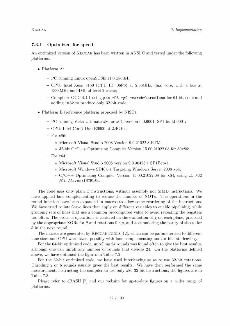
Keccak 7. Implementation
7.3.1 Optimized for speed
An optimized version of Keccak has been written in ANSI C and tested under the followingplatforms.
∙ Platform A:
– PC running Linux openSUSE 11.0 x86 64;
– CPU: Intel Xeon 5150 (CPU ID: 06F6) at 2.66GHz, dual core, with a bus at1333MHz and 4Mb of level-2 cache;
– Compiler: GCC 4.4.1 using gcc -O3 -g0 -march=barcelona for 64-bit code andadding -m32 to produce only 32-bit code.
∙ Platform B (reference platform proposed by NIST):
– PC running Vista Ultimate x86 or x64, version 6.0.6001, SP1 build 6001;
– CPU: Intel Core2 Duo E6600 at 2.4GHz;
– For x86:
∗ Microsoft Visual Studio 2008 Version 9.0.21022.8 RTM,
∗ 32-bit C/C++ Optimizing Compiler Version 15.00.21022.08 for 80x86;
– For x64:
∗ Microsoft Visual Studio 2008 version 9.0.30428.1 SP1Beta1,
∗ Microsoft Windows SDK 6.1 Targeting Windows Server 2008 x64,
∗ C/C++ Optimizing Compiler Version 15.00.21022.08 for x64, using cl /O2
/Ot /favor:INTEL64.
The code uses only plain C instructions, without assembly nor SIMD instructions. Wehave applied lane complementing to reduce the number of NOTs. The operations in theround function have been expanded in macros to allow some reordering of the instructions.We have tried to interleave lines that apply on different variables to enable pipelining, whilegrouping sets of lines that use a common precomputed value to avoid reloading the registerstoo often. The order of operations is centered on the evaluation of � on each plane, precededby the appropriate XORs for � and rotations for �, and accumulating the parity of sheets for� in the next round.
The macros are generated by KeccakTools [12], which can be parameterized to differentlane sizes and CPU word sizes, possibly with lane complementing and/or bit interleaving.
For the 64-bit optimized code, unrolling 24 rounds was found often to give the best results,although one can unroll any number of rounds that divides 24. On the platforms definedabove, we have obtained the figures in Table 7.2.
For the 32-bit optimized code, we have used interleaving so as to use 32-bit rotations.Unrolling 2 or 6 rounds usually gives the best results. We have then performed the samemeasurement, instructing the compiler to use only x86 32-bit instructions; the figures are inTable 7.3.
Please refer to eBASH [7] and our website for up-to-date figures on a wider range ofplatforms.
82 / 100
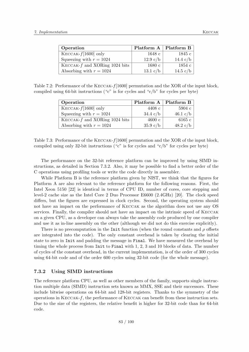
7. Implementation Keccak
Operation Platform A Platform B
Keccak-f [1600] only 1648 c 1845 cSqueezing with r = 1024 12.9 c/b 14.4 c/b
Keccak-f and XORing 1024 bits 1680 c 1854 cAbsorbing with r = 1024 13.1 c/b 14.5 c/b
Table 7.2: Performance of the Keccak-f [1600] permutation and the XOR of the input block,compiled using 64-bit instructions (“c” is for cycles and “c/b” for cycles per byte)
Operation Platform A Platform B
Keccak-f [1600] only 4408 c 5904 cSqueezing with r = 1024 34.4 c/b 46.1 c/b
Keccak-f and XORing 1024 bits 4600 c 6165 cAbsorbing with r = 1024 35.9 c/b 48.2 c/b
Table 7.3: Performance of the Keccak-f [1600] permutation and the XOR of the input block,compiled using only 32-bit instructions (“c” is for cycles and “c/b” for cycles per byte)
The performance on the 32-bit reference platform can be improved by using SIMD in-structions, as detailed in Section 7.3.2. Also, it may be possible to find a better order of theC operations using profiling tools or write the code directly in assembler.
While Platform B is the reference platform given by NIST, we think that the figures forPlatform A are also relevant to the reference platform for the following reasons. First, theIntel Xeon 5150 [22] is identical in terms of CPU ID, number of cores, core stepping andlevel-2 cache size as the Intel Core 2 Duo Processor E6600 (2.4GHz) [20]. The clock speeddiffers, but the figures are expressed in clock cycles. Second, the operating system shouldnot have an impact on the performance of Keccak as the algorithm does not use any OSservices. Finally, the compiler should not have an impact on the intrinsic speed of Keccakon a given CPU, as a developer can always take the assembly code produced by one compilerand use it as in-line assembly on the other (although we did not do this exercise explicitly).
There is no precomputation in the Init function (when the round constants and � offsetsare integrated into the code). The only constant overhead is taken by clearing the initialstate to zero in Init and padding the message in Final. We have measured the overhead bytiming the whole process from Init to Final with 1, 2, 3 and 10 blocks of data. The numberof cycles of the constant overhead, in the current implementation, is of the order of 300 cyclesusing 64-bit code and of the order 600 cycles using 32-bit code (for the whole message).
7.3.2 Using SIMD instructions
The reference platform CPU, as well as other members of the family, supports single instruc-tion multiple data (SIMD) instruction sets known as MMX, SSE and their successors. Theseinclude bitwise operations on 64-bit and 128-bit registers. Thanks to the symmetry of theoperations in Keccak-f , the performance of Keccak can benefit from these instruction sets.Due to the size of the registers, the relative benefit is higher for 32-bit code than for 64-bitcode.
83 / 100
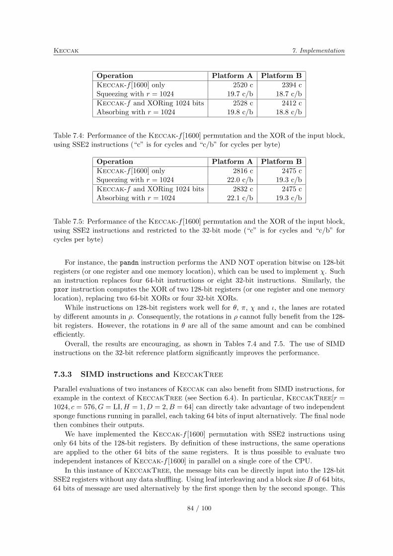
Keccak 7. Implementation
Operation Platform A Platform B
Keccak-f [1600] only 2520 c 2394 cSqueezing with r = 1024 19.7 c/b 18.7 c/b
Keccak-f and XORing 1024 bits 2528 c 2412 cAbsorbing with r = 1024 19.8 c/b 18.8 c/b
Table 7.4: Performance of the Keccak-f [1600] permutation and the XOR of the input block,using SSE2 instructions (“c” is for cycles and “c/b” for cycles per byte)
Operation Platform A Platform B
Keccak-f [1600] only 2816 c 2475 cSqueezing with r = 1024 22.0 c/b 19.3 c/b
Keccak-f and XORing 1024 bits 2832 c 2475 cAbsorbing with r = 1024 22.1 c/b 19.3 c/b
Table 7.5: Performance of the Keccak-f [1600] permutation and the XOR of the input block,using SSE2 instructions and restricted to the 32-bit mode (“c” is for cycles and “c/b” forcycles per byte)
For instance, the pandn instruction performs the AND NOT operation bitwise on 128-bitregisters (or one register and one memory location), which can be used to implement �. Suchan instruction replaces four 64-bit instructions or eight 32-bit instructions. Similarly, thepxor instruction computes the XOR of two 128-bit registers (or one register and one memorylocation), replacing two 64-bit XORs or four 32-bit XORs.
While instructions on 128-bit registers work well for �, �, � and �, the lanes are rotatedby different amounts in �. Consequently, the rotations in � cannot fully benefit from the 128-bit registers. However, the rotations in � are all of the same amount and can be combinedefficiently.
Overall, the results are encouraging, as shown in Tables 7.4 and 7.5. The use of SIMDinstructions on the 32-bit reference platform significantly improves the performance.
7.3.3 SIMD instructions and KeccakTree
Parallel evaluations of two instances of Keccak can also benefit from SIMD instructions, forexample in the context of KeccakTree (see Section 6.4). In particular, KeccakTree[r =1024, c = 576, G = LI, H = 1, D = 2, B = 64] can directly take advantage of two independentsponge functions running in parallel, each taking 64 bits of input alternatively. The final nodethen combines their outputs.
We have implemented the Keccak-f [1600] permutation with SSE2 instructions usingonly 64 bits of the 128-bit registers. By definition of these instructions, the same operationsare applied to the other 64 bits of the same registers. It is thus possible to evaluate twoindependent instances of Keccak-f [1600] in parallel on a single core of the CPU.
In this instance of KeccakTree, the message bits can be directly input into the 128-bitSSE2 registers without any data shuffling. Using leaf interleaving and a block size B of 64 bits,64 bits of message are used alternatively by the first sponge then by the second sponge. This
84 / 100
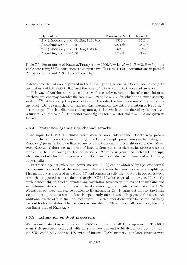
7. Implementation Keccak
Operation Platform A Platform B
2 × (Keccak-f and XORing 1024 bits) 2520 c 2511 cAbsorbing with r = 1024 9.8 c/b 9.8 c/b
2 × (Keccak-f and XORing 1088 bits) 2528 c 2520 cAbsorbing with r = 1088 9.3 c/b 9.3 c/b
Table 7.6: Performance of KeccakTree[r + c = 1600, G = LI, H = 1, D = 2, B = 64] on asingle core using SSE2 instructions to compute two Keccak-f [1600] permutations in parallel(“c” is for cycles and “c/b” for cycles per byte)
matches how the data are organized in the SSE2 registers, where 64 bits are used to computeone instance of Keccak-f [1600] and the other 64 bits to compute the second instance.
This way of working allows speeds below 10 cycles/byte/core on the reference platform.Furthermore, one may consider the case r = 1088 and c = 512, for which the claimed securitylevel is 2256. While losing the power of two for the rate, the final node needs to absorb onlyone block (Dc < r) and the overhead remains reasonable: one extra evaluation of Keccak-fper message. This benefits also to long messages, for which the number of cycles per byteis further reduced by 6%. The performance figures for r = 1024 and r = 1088 are given inTable 7.6.
7.3.4 Protection against side channel attacks
If the input to Keccak includes secret data or keys, side channel attacks may pose athreat. One can protect against timing attacks and simple power analysis by coding theKeccak-f permutation as a fixed sequence of instructions in a straightforward way. More-over, Keccak-f does not make use of large lookup tables so that cache attacks pose noproblem. (The interleaving method of Section 7.2.2 can be implemented with table lookups,which depend on the input message only. Of course, it can also be implemented without anytable at all.)
Protection against differential power analysis (DPA) can be obtained by applying severalmechanisms, preferably at the same time. One of the mechanisms is called state splitting.This method was proposed in [38] and [17] and consists in splitting the state in two parts—oneof which is supposed to be random—that give XORed back the actual state value. If properlyimplemented, this method eliminates any correlation between values inside the machine andany intermediate computation result, thereby removing the possibility for first-order DPA.We have shown how this can be applied to BaseKing in [28]. It turns out that for the linearsteps the computations can be done independently on the two split parts of the state. Anadditional overhead is in the non-linear steps, in which operations must be performed usingparts of both split states. The mechanisms described in [28] apply equally well to �, the onlynon-linear part of Keccak-f .
7.3.5 Estimation on 8-bit processors
We have estimated the performance of Keccak on the Intel 8051 microprocessor. The 8051is an 8-bit processor equipped with an 8-bit data bus and a 16-bit address bus. Initiallythe 8051 could only address 128 bytes of internal RAM memory, but later versions were
85 / 100
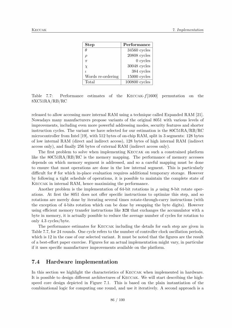
Keccak 7. Implementation
Step Performance
� 34560 cycles� 20808 cycles� 0 cycles� 30048 cycles� 384 cyclesWords re-ordering 15000 cycles
Total 100800 cycles
Table 7.7: Performance estimates of the Keccak-f [1600] permutation on the8XC51RA/RB/RC
released to allow accessing more internal RAM using a technique called Expanded RAM [21].Nowadays many manufacturers propose variants of the original 8051 with various levels ofimprovements, including even more powerful addressing modes, security features and shorterinstruction cycles. The variant we have selected for our estimation is the 80C51RA/RB/RCmicrocontroller from Intel [19], with 512 bytes of on-chip RAM, split in 3 segments: 128 bytesof low internal RAM (direct and indirect access), 128 bytes of high internal RAM (indirectaccess only), and finally 256 bytes of external RAM (indirect access only).
The first problem to solve when implementing Keccak on such a constrained platformlike the 80C51RA/RB/RC is the memory mapping. The performance of memory accessesdepends on which memory segment is addressed, and so a careful mapping must be doneto ensure that most operations are done in the low internal segment. This is particularlydifficult for � for which in-place evaluation requires additional temporary storage. Howeverby following a tight schedule of operations, it is possible to maintain the complete state ofKeccak in internal RAM, hence maximizing the performance.
Another problem is the implementation of 64-bit rotations in � using 8-bit rotate oper-ations. At first the 8051 does not offer specific instructions to optimize this step, and sorotations are merely done by iterating several times rotate-through-carry instructions (withthe exception of 4-bits rotation which can be done by swapping the byte digits). Howeverusing efficient memory transfer instructions like XCH that exchanges the accumulator with abyte in memory, it is actually possible to reduce the average number of cycles for rotation toonly 4.3 cycles/byte.
The performance estimates for Keccak including the details for each step are given inTable 7.7, for 24 rounds. One cycle refers to the number of controller clock oscillation periods,which is 12 in the case of our selected variant. It must be noted that the figures are the resultof a best-effort paper exercise. Figures for an actual implementation might vary, in particularif it uses specific manufacturer improvements available on the platform.
7.4 Hardware implementation
In this section we highlight the characteristics of Keccak when implemented in hardware.It is possible to design different architectures of Keccak. We will start describing the high-speed core design depicted in Figure 7.1. This is based on the plain instantiation of thecombinational logic for computing one round, and use it iteratively. A second approach is a
86 / 100
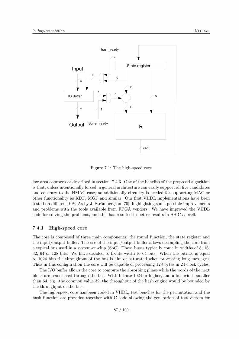
7. Implementation Keccak
Figure 7.1: The high-speed core
low area coprocessor described in section 7.4.3. One of the benefits of the proposed algorithmis that, unless intentionally forced, a general architecture can easily support all five candidatesand contrary to the HMAC case, no additionally circuitry is needed for supporting MAC orother functionality as KDF, MGF and similar. Our first VHDL implementations have beentested on different FPGAs by J. Strombergson [70], highlighting some possible improvementsand problems with the tools available from FPGA vendors. We have improved the VHDLcode for solving the problems, and this has resulted in better results in ASIC as well.
7.4.1 High-speed core
The core is composed of three main components: the round function, the state register andthe input/output buffer. The use of the input/output buffer allows decoupling the core froma typical bus used in a system-on-chip (SoC). These buses typically come in widths of 8, 16,32, 64 or 128 bits. We have decided to fix its width to 64 bits. When the bitrate is equalto 1024 bits the throughput of the bus is almost saturated when processing long messages.Thus in this configuration the core will be capable of processing 128 bytes in 24 clock cycles.
The I/O buffer allows the core to compute the absorbing phase while the words of the nextblock are transferred through the bus. With bitrate 1024 or higher, and a bus width smallerthan 64, e.g., the common value 32, the throughput of the hash engine would be bounded bythe throughput of the bus.
The high-speed core has been coded in VHDL, test benches for the permutation and thehash function are provided together with C code allowing the generation of test vectors for
87 / 100

Keccak 7. Implementation
Device Logic Registers Max Freq. Throughput
Altera StratixIII 4684 (38000) ALUTs 2641 (38000) 206 MHz 8.7 Gbit/sEP3SE50F484C2
Altera Cyclone III 5770 (10320) LEs 2641 (10320) 145 MHz 6.1 Gbit/sEP3C10F256C6
Virtex 5 1330 (7200) slices 2640 (28800) 122 MHz 5.2 Gbit/sXC5VLX50FF324-3
Table 7.8: Performance estimation of the high speed core on different FPGAs, and in bracketsthe resources available in the different cases.
the test benches. The core has been tested using ModelSim tools. In order to evaluate thesilicon area and the clock frequency, the core has been synthesized using Synopsys DesignCompiler and a 130 nm general purpose ST technology library, worst case 105∘C. The corecan reach a clock frequency of 526MHz, implying a throughput of 22.4 Gbit/s for bitrate1024.
The area needed for having the core running at this frequency is 48 kgate, composed of19 kgate for the round function, 9 kgate for the I/O buffer and 21 kgate for the state registerand control logic. The critical path of the combinatorial logic of the round function is only1.1 ns.
Five of the round-1 SHA-3 candidates have beed ported on STMicroelectronics 90nmtechnology by Nanim and Hasan [55]. The synthesis of high-speed Keccak using the sametechnology (worst case 105∘C and 0.90 V), results in a maximum frequency of 470 MHz (2.12ns of critical path), requiring 46 kgate. With this technology Keccak[] can guarantee athroughput of 20 Gbit/s.
We have used Altera Quartus II Web Edition version 9 [18] and Xilinx ISE WebPACKversion 11.1 [23] to evaluate VHDL with the tools for FPGA. These tools provide estimationsof the amount of resources needed and the maximum clock frequency reached. We report inTable 7.8 the estimation of the completed place and route.
For more details on the VHDL, refer to the readme.txt file in the VHDL directory of thesubmission package.
7.4.2 Variants of the high-speed core
The high-speed core can be modified to optimize for different aspects.
In many systems the clock frequency is fixed for the entire chip. So even if the hash core canreach a high frequency it has to be clocked at a lower frequency. In such a scenario Keccakallows to instantiate two, three or even six rounds in combinatorial logic and compute themin one clock cycle.
In the high-speed core we have decided to instantiate a separate buffer for the input/outputfunctions. This allows to run the absorbing phase while the bus is transferring the nextblock to be processed. An alternative for saving area is to execute the storing of the wordscomposing the block directly in the state register. This alternative allows to save about 8kgate and decreases the throughput to 12.8 Gbit/s at 500MHz, which is still a considerablyhigh value.
For a further reduction of the silicon area it is possible to compute one round in more
88 / 100
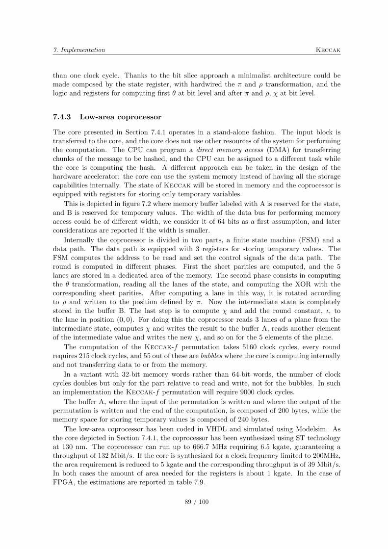
7. Implementation Keccak
than one clock cycle. Thanks to the bit slice approach a minimalist architecture could bemade composed by the state register, with hardwired the � and � transformation, and thelogic and registers for computing first � at bit level and after � and �, � at bit level.
7.4.3 Low-area coprocessor
The core presented in Section 7.4.1 operates in a stand-alone fashion. The input block istransferred to the core, and the core does not use other resources of the system for performingthe computation. The CPU can program a direct memory access (DMA) for transferringchunks of the message to be hashed, and the CPU can be assigned to a different task whilethe core is computing the hash. A different approach can be taken in the design of thehardware accelerator: the core can use the system memory instead of having all the storagecapabilities internally. The state of Keccak will be stored in memory and the coprocessor isequipped with registers for storing only temporary variables.
This is depicted in figure 7.2 where memory buffer labeled with A is reserved for the state,and B is reserved for temporary values. The width of the data bus for performing memoryaccess could be of different width, we consider it of 64 bits as a first assumption, and laterconsiderations are reported if the width is smaller.
Internally the coprocessor is divided in two parts, a finite state machine (FSM) and adata path. The data path is equipped with 3 registers for storing temporary values. TheFSM computes the address to be read and set the control signals of the data path. Theround is computed in different phases. First the sheet parities are computed, and the 5lanes are stored in a dedicated area of the memory. The second phase consists in computingthe � transformation, reading all the lanes of the state, and computing the XOR with thecorresponding sheet parities. After computing a lane in this way, it is rotated accordingto � and written to the position defined by �. Now the intermediate state is completelystored in the buffer B. The last step is to compute � and add the round constant, �, tothe lane in position (0, 0). For doing this the coprocessor reads 3 lanes of a plane from theintermediate state, computes � and writes the result to the buffer A, reads another elementof the intermediate value and writes the new �, and so on for the 5 elements of the plane.
The computation of the Keccak-f permutation takes 5160 clock cycles, every roundrequires 215 clock cycles, and 55 out of these are bubbles where the core is computing internallyand not transferring data to or from the memory.
In a variant with 32-bit memory words rather than 64-bit words, the number of clockcycles doubles but only for the part relative to read and write, not for the bubbles. In suchan implementation the Keccak-f permutation will require 9000 clock cycles.
The buffer A, where the input of the permutation is written and where the output of thepermutation is written and the end of the computation, is composed of 200 bytes, while thememory space for storing temporary values is composed of 240 bytes.
The low-area coprocessor has been coded in VHDL and simulated using Modelsim. Asthe core depicted in Section 7.4.1, the coprocessor has been synthesized using ST technologyat 130 nm. The coprocessor can run up to 666.7 MHz requiring 6.5 kgate, guaranteeing athroughput of 132 Mbit/s. If the core is synthesized for a clock frequency limited to 200MHz,the area requirement is reduced to 5 kgate and the corresponding throughput is of 39 Mbit/s.In both cases the amount of area needed for the registers is about 1 kgate. In the case ofFPGA, the estimations are reported in table 7.9.
89 / 100
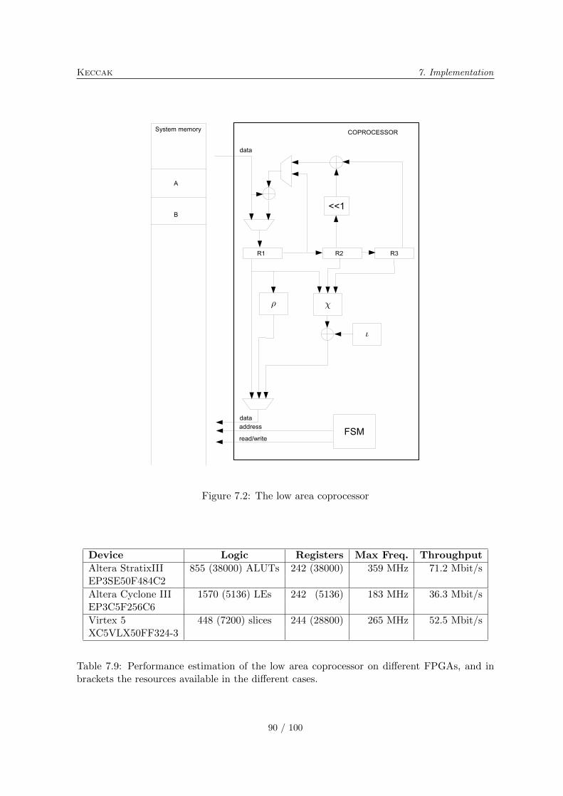
Keccak 7. Implementation
Figure 7.2: The low area coprocessor
Device Logic Registers Max Freq. Throughput
Altera StratixIII 855 (38000) ALUTs 242 (38000) 359 MHz 71.2 Mbit/sEP3SE50F484C2
Altera Cyclone III 1570 (5136) LEs 242 (5136) 183 MHz 36.3 Mbit/sEP3C5F256C6
Virtex 5 448 (7200) slices 244 (28800) 265 MHz 52.5 Mbit/sXC5VLX50FF324-3
Table 7.9: Performance estimation of the low area coprocessor on different FPGAs, and inbrackets the resources available in the different cases.
90 / 100
7. Implementation Keccak
It is interesting to note that the low area coprocessor is capable of reaching higher fre-quencies compared to the high speed core.
This kind of coprocessor is suitable for smart cards or wireless sensor network where areais particularly important since it determines the cost of the device and there is not a richoperating system allowing to run different processes in parallel.
7.4.4 Protection against side channel attacks
Due to the simplicity of the round logic, and the use of simple 2-input gates, it is possibleto use logic gates resistant to power analysis, like WDDL [71] or SecLib [39]. These typesof logic are evolutions of the dual rail logic, where a bit is coded using two lines in such away that all the logic gates consume the same amount of energy independently of the values.Additionally, the fact that the non-linear component of Keccak-f is limited to binary ANDgates, it lends itself very well for the very powerful protection techniques based on secretsharing proposed in [66] that can offer effective protection against glitches.
91 / 100

Keccak 7. Implementation
92 / 100
Bibliography
[1] J.-P. Aumasson, I. Dinur, W. Meier, and A. Shamir, Cube testers and key recoveryattacks on reduced-round MD6 and Trivium, FSE (O. Dunkelman, ed.), Lecture Notesin Computer Science, vol. 5665, Springer, 2009, pp. 1–22.
[2] J.-P. Aumasson and D. Khovratovich, First analysis of Keccak, Available online, 2009,http://131002.net/data/papers/AK09.pdf.
[3] J.-P. Aumasson and W. Meier, Zero-sum distinguishers for reduced Keccak-f and for thecore functions of luffa and hamsi, Available online, 2009, http://131002.net/data/
papers/AM09.pdf.
[4] T. Baigneres, J. Stern, and S. Vaudenay, Linear cryptanalysis of non binary ciphers,Selected Areas in Cryptography (C. M. Adams, A. Miri, and M. J. Wiener, eds.), LectureNotes in Computer Science, vol. 4876, Springer, 2007, pp. 184–211.
[5] M. Bellare, R. Canetti, and H. Krawczyk, Keying hash functions for message authentica-tion, Advances in Cryptology – Crypto ’96 (N. Koblitz, ed.), LNCS, no. 1109, Springer-Verlag, 1996, pp. 1–15.
[6] D. J. Bernstein, The Salsa20 family of stream ciphers, 2007, Document ID:31364286077dcdff8e4509f9ff3139ad, http://cr.yp.to/papers.html#salsafamily.
[7] D. J. Bernstein and T. Lange (editors), eBACS: ECRYPT Benchmarking of cryptographicsystems, http://bench.cr.yp.to, accessed 21 December 2008.
[8] G. Bertoni, J. Daemen, M. Peeters, and G. Van Assche, RadioGatun, a belt-and-mill hash function, Second Cryptographic Hash Workshop, Santa Barbara, August 2006,http://radiogatun.noekeon.org/.
[9] , Sponge functions, Ecrypt Hash Workshop 2007, May 2007, also available as pub-lic comment to NIST from http://www.csrc.nist.gov/pki/HashWorkshop/Public_
Comments/2007_May.html.
[10] , On the indifferentiability of the sponge construction, Advances in Cryptology– Eurocrypt 2008 (N. P. Smart, ed.), Lecture Notes in Computer Science, vol. 4965,Springer, 2008, http://sponge.noekeon.org/, pp. 181–197.
[11] , Keccak specifications, version 2, NIST SHA-3 Submission, September 2009,http://keccak.noekeon.org/.
[12] , KeccakTools software, January 2009, http://keccak.noekeon.org/.
93 / 100
Keccak BIBLIOGRAPHY
[13] , Sufficient conditions for sound tree hashing modes, Cryptology ePrint Archive,Report 2009/210, 2009, http://eprint.iacr.org/.
[14] E. Biham, O. Dunkelman, and N. Keller, The rectangle attack - rectangling the ser-pent, Advances in Cryptology – Eurocrypt 2001 (B. Pfitzmann, ed.), Lecture Notes inComputer Science, vol. 2045, Springer, 2001, pp. 340–357.
[15] C. Bouillaguet and P.-A. Fouque, Analysis of the collision resistance of RadioGatunusing algebraic techniques, Selected Areas in Cryptography, Lecture Notes in ComputerScience, vol. 4876, Springer, 2008.
[16] R. Canetti, O. Goldreich, and S. Halevi, The random oracle methodology, revisited, Pro-ceedings of the 30th Annual ACM Symposium on the Theory of Computing, ACM Press,1998, pp. 209–218.
[17] S. Chari, C. S. Jutla, J. R. Rao, and P. Rohatgi, Towards sound approaches to counteractpower-analysis attacks, Advances in Cryptology – Crypto ’99 (M. J. Wiener, ed.), LectureNotes in Computer Science, vol. 1666, Springer, 1999, pp. 398–412.
[18] Altera corporation, Quartus II web edition software, http://www.altera.com.
[19] Intel Corporation, Intel 8XC51RA/RB/RC hardware description, http://www.intel.com/design/mcs51/manuals/272668.htm.
[20] , Intel R⃝ CoreTM2 Duo Desktop Processor E6600, http://processorfinder.
intel.com/details.aspx?sSpec=SL9S8.
[21] , Intel MCS 51/251 microcontrollers - expanded RAM, http://www.intel.com/design/mcs51/er_51.htm.
[22] , Intel R⃝ Xeon R⃝ Processor 5150, http://processorfinder.intel.com/
details.aspx?sSpec=SL9RU.
[23] Xilinx corporation, ISE WebPACK software, http://www.xilinx.com.
[24] D. A. Cox, J. B. Little, and D. O’Shea, Ideals, varieties, and algorithms, third ed.,Springer, 2007.
[25] J. Daemen, Cipher and hash function design strategies based on linear and differentialcryptanalysis, PhD thesis, K.U.Leuven, 1995.
[26] J. Daemen and C. S. K. Clapp, Fast hashing and stream encryption with PANAMA, FastSoftware Encryption 1998 (S. Vaudenay, ed.), LNCS, no. 1372, Springer-Verlag, 1998,pp. 60–74.
[27] J. Daemen, L. R. Knudsen, and V. Rijmen, The block cipher Square, Fast SoftwareEncryption 1997 (E. Biham, ed.), Lecture Notes in Computer Science, vol. 1267, Springer,1997, pp. 149–165.
[28] J. Daemen, M. Peeters, and G. Van Assche, Bitslice ciphers and power analysis attacks,in Schneier [68], pp. 134–149.
94 / 100
BIBLIOGRAPHY Keccak
[29] J. Daemen, M. Peeters, G. Van Assche, and V. Rijmen, Nessie proposal: the block ciphernoekeon, Nessie submission, 2000, http://gro.noekeon.org/.
[30] J. Daemen and V. Rijmen, The design of Rijndael — AES, the advanced encryptionstandard, Springer-Verlag, 2002.
[31] , Probability distributions of correlation and differentials in block ciphers, Journalof Mathematical Cryptology 1 (2007), no. 3, 221–242.
[32] I. Dinur and A. Shamir, Cube attacks on tweakable black box polynomials, CryptologyePrint Archive, Report 2008/385, 2008, http://eprint.iacr.org/.
[33] N. Ferguson, S. Lucks, B. Schneier, D. Whiting, M. Bellare, T. Kohno, J. Callas,and J. Walker, The Skein hash function family, Submission to NIST, 2008, http:
//skein-hash.info/.
[34] E. Filiol, A new statistical testing for symmetric ciphers and hash functions, Proc. In-formation and Communications Security 2002, volume 2513 of LNCS, Springer, 2002,pp. 342–353.
[35] IETF (Internet Engineering Task Force), RFC 3629: UTF-8, a transformation formatof ISO 10646, 2003, http://www.ietf.org/rfc/rfc3629.txt.
[36] , RFC 3986: Uniform resource identifier (URI): Generic syntax, 2005, http:
//www.ietf.org/rfc/rfc3986.txt.
[37] G. Gielen and J. Figueras (eds.), 2004 design, automation and test in Europe confer-ence and exposition (DATE 2004), 16-20 February 2004, Paris, France, IEEE ComputerSociety, 2004.
[38] L. Goubin and J. Patarin, DES and differential power analysis (the duplication method),CHES (C. K. Koc and C. Paar, eds.), Lecture Notes in Computer Science, vol. 1717,Springer, 1999, pp. 158–172.
[39] S. Guilley, P. Hoogvorst, Y. Mathieu, R. Pacalet, and J. Provost, CMOS structuressuitable for secured hardware, in Gielen and Figueras [37], pp. 1414–1415.
[40] IEEE, P1363-2000, standard specifications for public key cryptography, 2000.
[41] A. Joux, Multicollisions in iterated hash functions. Application to cascaded constructions,Advances in Cryptology – Crypto 2004 (M. Franklin, ed.), LNCS, no. 3152, Springer-Verlag, 2004, pp. 306–316.
[42] J. Kelsey, T. Kohno, and B. Schneier, Amplified boomerang attacks against reduced-roundmars and serpent, in Schneier [68], pp. 75–93.
[43] J. Kelsey and B. Schneier, Second preimages on n-bit hash functions for much less than2n work, Advances in Cryptology – Eurocrypt 2005 (R. Cramer, ed.), LNCS, no. 3494,Springer-Verlag, 2005, pp. 474–490.
[44] D. Khovratovich, Two attacks on RadioGatun, 9th International Conference on Cryptol-ogy in India, 2008.
95 / 100
Keccak BIBLIOGRAPHY
[45] L. Knudsen, C. Rechberger, and S. Thomsen, Grindahl - a family of hash functions, FastSoftware Encryption 2007 (A. Biryukov, ed.), LNCS, Springer-Verlag, 2007, pp. 39–47.
[46] L. R. Knudsen, Truncated and higher order differentials, Fast Software Encryption 1994(B. Preneel, ed.), Lecture Notes in Computer Science, vol. 1008, Springer, 1994, pp. 196–211.
[47] L. R. Knudsen and V. Rijmen, Known-key distinguishers for some block ciphers, Ad-vances in Cryptology – Asiacrypt 2007, 2007, pp. 315–324.
[48] D. E. Knuth, The art of computer programming, vol. 2, third edition, Addison-WesleyPublishing Company, 1998.
[49] T. Kohno and J. Kelsey, Herding hash functions and the Nostradamus attack, Advancesin Cryptology – Eurocrypt 2006 (S. Vaudenay, ed.), LNCS, no. 4004, Springer-Verlag,2006, pp. 222–232.
[50] RSA Laboratories, PKCS # 1 v2.1 RSA Cryptography Standard, 2002.
[51] S. K. Langford and M. E. Hellman, Differential-linear cryptanalysis, Advances in Cryp-tology – Crypto ’94 (Y. Desmedt, ed.), Lecture Notes in Computer Science, vol. 839,Springer, 1994, pp. 17–25.
[52] J. Lathrop, Cube attacks on cryptographic hash functions, Master’s thesis, Availableonline, 2009, http://www.cs.rit.edu/˜jal6806/thesis/.
[53] U. Maurer, R. Renner, and C. Holenstein, Inidifferentiability, impossibility results onreductions, and applications to the random oracle methodology, Theory of Cryptography- TCC 2004 (M. Naor, ed.), Lecture Notes in Computer Science, no. 2951, Springer-Verlag, 2004, pp. 21–39.
[54] R. C. Merkle, Secrecy, authentication, and public key systems, PhD thesis, UMI ResearchPress, 1982.
[55] A.H. Namin and M. A. Hasan, Hardware implementation of the compressionfunction for selected sha-3 candidates, Technical Report CACR 2009-28, 2009,(http://www.cacr.math.uwaterloo.ca/techreports/2009/cacr2009-28.pdf.
[56] NIST, Federal information processing standard 186-3, digital signature standard (DSS),March 2006.
[57] , Announcing request for candidate algorithm nominations for a new cryptographichash algorithm (SHA-3) family, Federal Register Notices 72 (2007), no. 212, 62212–62220, http://csrc.nist.gov/groups/ST/hash/index.html.
[58] , NIST special publication 800-106 draft, randomized hashing digital signatures,July 2007.
[59] , NIST special publication 800-56a, recommendation for pair-wise key establish-ment schemes using discrete logarithm cryptography (revised), March 2007.
[60] , NIST special publication 800-90, recommendation for random number generationusing deterministic random bit generators (revised), March 2007.
96 / 100
BIBLIOGRAPHY Keccak
[61] , ANSI C cryptographic API profile for SHA-3 candidate algorithm submissions,revision 5, February 2008, available from http://csrc.nist.gov/groups/ST/hash/
sha-3/Submission_Reqs/crypto_API.html.
[62] , Federal information processing standard 198, the keyed-hash message authenti-cation code (HMAC), July 2008.
[63] , NIST special publication 800-108, recommendation for key derivation using pseu-dorandom functions, April 2008.
[64] R. L. Rivest, M. J. B. Robshaw, R. Sidney, and Y. L. Yin, The RC6 block cipher, AESproposal, August 1998.
[65] P. Sarkar and P. J. Schellenberg, A parallelizable design principle for cryptographic hashfunctions, Cryptology ePrint Archive, Report 2002/031, 2002, http://eprint.iacr.
org/.
[66] M. Schlaffer, Masking non-linear functions based on secret sharing, Echternach Symmet-ric Cryptography seminar, 2008, http://wiki.uni.lu/esc/.
[67] B. Schneier, Applied cryptography, second ed., John Wiley & Sons, 1996.
[68] B. Schneier (ed.), Fast software encryption, 7th international workshop, fse 2000, newyork, ny, usa, april 10-12, 2000, proceedings, Lecture Notes in Computer Science, vol.1978, Springer, 2001.
[69] W. A. Stein et al., Sage Mathematics Software, The Sage Development Team, 2009,http://www.sagemath.org/.
[70] J. Strombergson, Implementation of the Keccak hash function in FPGA devices, http://www.strombergson.com/files/Keccak_in_FPGAs.pdf.
[71] K. Tiri and I. Verbauwhede, A logic level design methodology for a secure DPA resistantASIC or FPGA implementation, in Gielen and Figueras [37], pp. 246–251.
[72] W3C, Namespaces in XML 1.0 (second edition), 2006, http://www.w3.org/TR/2006/REC-xml-names-20060816.
[73] D. Wagner, The boomerang attack, Fast Software Encryption 1999 (L. R. Knudsen, ed.),Lecture Notes in Computer Science, vol. 1636, Springer, 1999, pp. 156–170.
[74] R. Wernsdorf, The round functions of Rijndael generate the alternating group, Fast Soft-ware Encryption 2002 (J. Daemen and V. Rijmen, eds.), Lecture Notes in ComputerScience, vol. 2365, Springer, 2002, pp. 143–148.
[75] Wikipedia, Cryptographic hash function, 2008, http://en.wikipedia.org/wiki/
Cryptographic_hash_function.
[76] , Impossible differential cryptanalysis, 2008, http://en.wikipedia.org/wiki/
Miss_in_the_middle_attack.
[77] , Random permutation statistics, 2008, http://en.wikipedia.org/wiki/
Random_permutation_statistics.
97 / 100

Keccak BIBLIOGRAPHY
[78] M. R. Z’aba, H. Raddum, M. Henricksen, and E. Dawson, Bit-pattern based integralattack, Fast Software Encryption 2008 (K. Nyberg, ed.), Lecture Notes in ComputerScience, vol. 5086, Springer, 2008, pp. 363–381.
98 / 100
Appendix A
Change log
A.1 From 1.2 to 2.0
∙ Adaptation of the specifications summary to the modified number of rounds of Keccak-fin Section 1.1.
∙ Update of the acknowledgements in Section 1.3.
∙ Update of Section 2.4 to reflect the modified parameters.
∙ Addition of Section 2.5 motivating the parameter change between version 1 and version2 of Keccak.
∙ Update of Section 3.3 to reflect the new choice for capacity and bitrate for the fixed-output-length SHA-3 candidates
∙ Update of Section 4.2.3 to include an introduction of cube attacks and testers.
∙ Update of our estimates for the required number of rounds in Keccak-f for providingresistance against different types of distinguishers and attacks in Section 5.4.
∙ Addition of two entries in Table 5.2 in Section 5.5.10.
∙ Mentioning of the CICO-solving results of [2] in Section 5.6.
∙ Addition of Section 5.7 discussing third-party cryptanalysis based on low-degree poly-nomials.
∙ Addition of Section 5.11 reporting on our results of particular trails called tame trails.
∙ Encoding of B in bytes (instead of multiples of 64 bits) in Section 6.4.
∙ Discussion on soundness of the tree hashing mode in Section 6.4.2.
∙ Update of performance figures in Chapter 7.
99 / 100
Keccak A. Change log
A.2 From 1.1 to 1.2
∙ In Chapter 1, we added Section 1.1 with a 2-page specifications summary of Keccak.
∙ In Section 5.3.1, we provide more explanations on difference propagation and correlationproperties of �.
∙ In Section 5.10.3, we present ANF tests also on the inverse of Keccak-f .
∙ In Section 7.3, updates have been made to the software performance in general andregarding SIMD instructions in particular, see Sections 7.3.2 and 7.3.3.
A.3 From 1.0 to 1.1
∙ Sections 2.2 and 4.1 now explicitly mention the hermetic sponge strategy.
∙ Chapter 6 proposes additional usage ideas for Keccak, including input formattingand diversification (see Section 6.3), and parallel and tree hashing (see Section 6.4).Section 6.1 now also mentions a slow one-way function.
∙ New techniques and updated implementation figures are added to Chapter 7.
– Section 7.2.1 presents the lane complementing transform.
– Section 7.2.2 shows how to use the bit interleaving technique.
– Section 7.3 has been reorganized to show the results on the two platforms side byside.
– Section 7.3.1 display updated performance figures.
– Sections 7.4.1 and 7.4.3 report updated performance figures on ASIC and newfigures on FPGA.
100 / 100
![KangarooTwelve: fast hashing based on Keccak-p · of a tree hash mode with Sakura encoding [29,9] and the sponge construc-tion [7], both proven secure. Its underlying permutation](https://static.fdocuments.us/doc/165x107/5f3b8c6521687b4b7e5aba24/kangarootwelve-fast-hashing-based-on-keccak-p-of-a-tree-hash-mode-with-sakura-encoding.jpg)


![Practical Collision Attacks against Round-Reduced SHA-3The Keccak hash function [3] was a submission to the SHA-3 competition [22] in 2008. After four years of intensive evaluation,](https://static.fdocuments.us/doc/165x107/6015db24e354c42e3621d1a9/practical-collision-attacks-against-round-reduced-sha-3-the-keccak-hash-function.jpg)


