Katalog 2505 0404 D/GB - ahrinternational.com€¦ · The "field weakening" characteristics provide...
47
3 Katalog 2505 0404 Catalog 2505 0404 Inhaltsverzeichnis Index Fertigungsprogramm 4 Manufacturing program Spindeltypen - Übersicht 5 Spindle types - Overview Aufbau und Ausstattung der HC-/HCS-Reihe Design and features of HC-/HCS style Abnehmbare Leistung 6 Shaft output power Vorteile durch Hybridlager 7 - 8 Advantages of hybrid ceramic bearings Die Werkzeugaufnahme 9 Tool interface Das Werkzeugspannsystem 10 Clamping systems Positionssensoren 11 Position sensors Drehwinkelgeber für feldorientierte Regelung 12 Integral encoders for closed loop drive Sperrluftabdichtung 13 Air purge Kegelreinigen 14 Taper cleaning Innere Kühlmittel-Zuführung 14 Coolant through shaft Kühlmittel durch Gehäuse 15 Coolant through spindle housing Einstellbare Lagervorspannung 16 Adjustable bearing preload Temperaturmessung am Außenring des vorderen Lagers 17 A method for controlling axial shaft growth Messung der axialen Wellenverlagerung mittels Sensor 18 Measurement of the axial shaft growth by sensor Vibrationssensor 19 Vibration sensor Interne Minimalmengenschmierung - Einkanalsystem 20 Internal minimized coolant supply - Single-channel system Interne Minimalmengenschmierung - Zweikanalsystem 21 Internal minimized coolant supply - Two-channel system Schnell-Kupplung / Multi-Kupplung 22 Quick couplings / Multi couplings Abmessungen und Merkmale der Spindeltypen 23 - 49 Dimensions and characteristics of the spindle types Qualitätsstandard 50 Quality standard
Transcript of Katalog 2505 0404 D/GB - ahrinternational.com€¦ · The "field weakening" characteristics provide...
3
Katalog 25050404Catalog 25050404InhaltsverzeichnisIndex
F e r t i g u n g s p r o g r a m m 4M a n u f a c t u r i n g p r o g r a m
S p i n d e l t y p e n - Ü b e r s i c h t 5S p i n d l e t y p e s - O v e r v i e w
A u f b a u u n d A u s s t a t t u n g d e r H C - / H C S - R e i h eD e s i g n a n d f e a t u r e s o f H C - / H C S s t y l e
Abnehmba re Le i s t ung 6Sha f t ou tpu t powe r
Vor te i l e du r ch Hyb r i d l age r 7 - 8Advan tages o f hyb r i d ce ram ic bea r i ngs
Die Werkzeugau fnahme 9Too l i n t e r f ace
Das Werkzeugspannsys tem 1 0Clamp ing sys tems
Pos i t i onssenso ren 1 1Pos i t i on senso rs
Drehw inke lgebe r f ü r f e l do r i en t i e r t e Rege lung 1 2I n t eg ra l encode rs f o r c l osed l oop d r i ve
Spe r r l u f t abd i ch tung 1 3A i r pu rge
Kege l r e i n i gen 1 4Tape r c l ean ing
I nne re Küh lm i t t e l -Zu füh rung 1 4Coo lan t t h rough sha f t
Küh lm i t t e l du r ch Gehäuse 1 5Coo lan t t h rough sp i nd l e hous i ng
E ins te l l ba re Lage rvo r spannung 1 6Ad jus tab l e bea r i ng p re l oad
Tempera tu rmessung am Außen r i ng des vo rde ren Lage rs 1 7A me thod f o r con t r o l l i ng ax i a l sha f t g row th
Messung de r ax i a l en We l l enve r l age rung m i t t e l s Senso r 1 8Measu remen t o f t he ax i a l sha f t g row th by senso r
V ib ra t i onssenso r 1 9V ib ra t i on senso r
I n t e rne M in ima lmengenschm ie rung - E i nkana l sys tem 2 0I n t e rna l m in im i zed coo lan t supp l y - S i ng l e - channe l s ys tem
I n t e rne M in ima lmengenschm ie rung - Zwe i kana l sys tem 2 1I n t e rna l m in im i zed coo lan t supp l y - Two -channe l s ys tem
Schne l l -Kupp lung / Mu l t i -Kupp lung 2 2Qu ick coup l i ngs / Mu l t i coup l i ngs
A b m e s s u n g e n u n d M e r k m a l e d e r S p i n d e l t y p e n 2 3 - 4 9D i m e n s i o n s a n d c h a r a c t e r i s t i c s o f t h e s p i n d l e t y p e s
Q u a l i t ä t s s t a n d a r d 5 0Q u a l i t y s t a n d a r d
WEHRFRIT
WEHRFRIT
Ausgabe / Edition 2505 / 2004-04-06

�
������������ ���������������� �
��������������������
��
�������������� ����������������������� ������
������������������� ��������������������������������������
������������������������������������
������������������������������������������������������ �������������� �������!�
���"������#��������"��������
$�%&�������������'�����������$�������������������������������
(��� )���� ������*� ���� ���������$���������������������#������������
����&�����������������������������������&����������+�������������������������������������
'�����������������������������������(���������������,��������������
��������������������������������
��������������������������� ������
���-���-��
��������.���������������������������/
0�������������+���������
1�������������%���2��������������������������
����������3���������������
$�%&���� 4��� (�%���4�� �������������������
���5���%���3������������
6��������%���3������������
$�����%����������������
+������%���.������������
2����������������������������������������7�������������������������������������
WEHRFRIT
Ausgabe / Edition 2505 / 2004-04-06

5
Spindeltyp
Spindle type
Gehäuse- max. abdurchmesser Drehzahl Leistung Drehzahl Moment Schmierart Werkzeugaufnahme Lager W1
[mm] [1/min] [kW] [1/min] [Nm] [mm]
Housing max. fromdiameter speed Output speed Torque Lubrication Tool interface Bearing W1
[mm] [rpm] [kW] [rpm] [Nm] [mm]
HC 80 cg - 40000 / 2,2 80 40000 2,2 40000 0,53 g HSK - E 25 30
HCS 100 cg - 40000 / 3,9 100 40000 3,9 9710 3,8 g HSK - E 25 30
HC 120 - 42000 / 11 120 42000 11 30000 3,5 OL HSK - E 40 / SK 30 45
HC 120 - 50000 / 11 120 50000 11 30000 3,5 OL HSK - E 32 40
HC 120 - 60000 / 5,5 120 60000 5,5 60000 0,9 OL HSK - E 25 30
HCS 150 - 42000 / 30 150 42000 30 21000 13,7 OL HSK - E 50 55
HCS 150 - 42000 / 32 150 42000 32 30000 10,2 OL HSK - E 50 55
HCS 150 g - 18000 / 9 150 18000 9 7500 11 g HSK - A 50 55
HCS 170 - 24000 / 20 170 24000 20 5000 38 OL HSK - A 63 70
HCS 170 - 24000 / 27 170 24000 27 18000 14 OL HSK - A 63 70
HCS 170 - 24000 / 41 170 24000 41 7000 56 OL HSK - A 63 70
HCS 170 - 40000 / 39 170 40000 39 15000 24,8 OL HSK - E 50 55
HCS 170 g - 15000 / 41 170 15000 41 7000 56 g HSK - A 63 70
HCS 200 - 18000 / 15 200 18000 15 1800 80 OL HSK - A 63 80
HCS 200 - 30000 / 15 200 30000 15 12000 12 OL HSK - A 50 / E 50 55
HCS 200 - 30000 / 46 200 30000 46 15000 29,3 OL HSK - E 63 70
HCS 200 g - 12000 / 15 200 12000 15 1800 80 g SK - 40 80
HCS 230 - 24000 / 18 230 24000 18 3150 57 OL HSK - A 63 70
HCS 230 - 30000 / 80 230 30000 80 13500 56,6 OL HSK - A 63 70
HCS 230 g - 10000 / 24 230 10000 24 2500 91,7 g HSK - A 63 90
HCS 230 g - 16000 / 24 230 16000 24 6000 38,2 g HSK - A 63 70
HCS 232 g - 15000 / 9 232 15000 9 1220 70 g HSK - A 63 80
HCS 275 - 20000 / 60 275 20000 60 10000 57 OL HSK - A 63 70
HCS 285 - 12000 / 32 285 12000 32 1000 306 OL HSK - A 100 110
HCS 300 - 12000 / 30 300 12000 30 1000 270 OL HSK - A 100 110
HCS 300 g - 8000 / 30 300 8000 30 1000 286 g HSK - A 100 110
HCS 310 - 12000 / 25 310 12000 25 930 256,7 OL HSK - A 100 110
HC / HCS - Spindeln
max. Leistung S1 [kW] max. power S1 [kW]max. Drehzahl [1/min] max. speed [rpm]Gehäusedurchmesser [mm] housing diameter [mm]Spindeltyp spindle type
HCS = geregelter Antrieb HCS = for vectordrive
Vorzugsspindeln preference typeSonderspindeln non-preference type
W1 = Bohrungsdurchmesser der bore diameter of front bearingsvorderen Lagergruppe
OL = Öl-Luft-Schmierung oil/air lubricationg = Fett-Dauerschmierung permanently grease lubricated
SK = Steilkegel ISO taperHSK = Hohlschaftkegel hollow tapered shank
Wenn Sie eine Spindelzeichnung wünschen,schicken wir Ihnen diese gerne als dxf-file zu.Please ask if spindle drawing is required. We send it as dxf file.
WEHRFRIT
Ausgabe / Edition 2505 / 2004-04-06
6
Drehzahl n [1/min] / Speed n [rpm]
LeistungPowerP [kW]
abnehmbare Leistung
Shaft output power
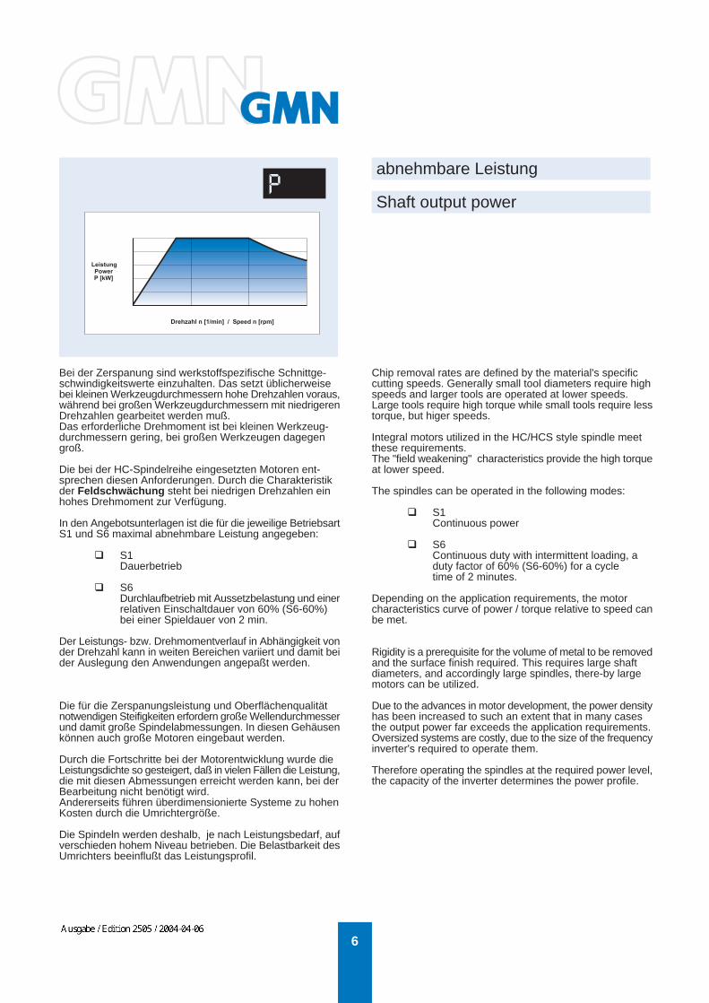
Bei der Zerspanung sind werkstoffspezifische Schnittge-schwindigkeitswerte einzuhalten. Das setzt üblicherweisebei kleinen Werkzeugdurchmessern hohe Drehzahlen voraus,während bei großen Werkzeugdurchmessern mit niedrigerenDrehzahlen gearbeitet werden muß.Das erforderliche Drehmoment ist bei kleinen Werkzeug-durchmessern gering, bei großen Werkzeugen dagegengroß.
Die bei der HC-Spindelreihe eingesetzten Motoren ent-sprechen diesen Anforderungen. Durch die Charakteristikder Feldschwächung steht bei niedrigen Drehzahlen einhohes Drehmoment zur Verfügung.
In den Angebotsunterlagen ist die für die jeweilige BetriebsartS1 und S6 maximal abnehmbare Leistung angegeben:
S1Dauerbetrieb
S6Durchlaufbetrieb mit Aussetzbelastung und einerrelativen Einschaltdauer von 60% (S6-60%)bei einer Spieldauer von 2 min.
Der Leistungs- bzw. Drehmomentverlauf in Abhängigkeit vonder Drehzahl kann in weiten Bereichen variiert und damit beider Auslegung den Anwendungen angepaßt werden.
Die für die Zerspanungsleistung und Oberflächenqualitätnotwendigen Steifigkeiten erfordern große Wellendurchmesserund damit große Spindelabmessungen. In diesen Gehäusenkönnen auch große Motoren eingebaut werden.
Durch die Fortschritte bei der Motorentwicklung wurde dieLeistungsdichte so gesteigert, daß in vielen Fällen die Leistung,die mit diesen Abmessungen erreicht werden kann, bei derBearbeitung nicht benötigt wird.Andererseits führen überdimensionierte Systeme zu hohenKosten durch die Umrichtergröße.
Die Spindeln werden deshalb, je nach Leistungsbedarf, aufverschieden hohem Niveau betrieben. Die Belastbarkeit desUmrichters beeinflußt das Leistungsprofil.
Chip removal rates are defined by the material's specificcutting speeds. Generally small tool diameters require highspeeds and larger tools are operated at lower speeds.Large tools require high torque while small tools require lesstorque, but higer speeds.
Integral motors utilized in the HC/HCS style spindle meetthese requirements.The "field weakening" characteristics provide the high torqueat lower speed.
The spindles can be operated in the following modes:
S1Continuous power
S6Continuous duty with intermittent loading, a duty factor of 60% (S6-60%) for a cycle time of 2 minutes.
Depending on the application requirements, the motorcharacteristics curve of power / torque relative to speed canbe met.
Rigidity is a prerequisite for the volume of metal to be removedand the surface finish required. This requires large shaftdiameters, and accordingly large spindles, there-by largemotors can be utilized.
Due to the advances in motor development, the power densityhas been increased to such an extent that in many casesthe output power far exceeds the application requirements.Oversized systems are costly, due to the size of the frequencyinverter's required to operate them.
Therefore operating the spindles at the required power level,the capacity of the inverter determines the power profile.
WEHRFRIT
Ausgabe / Edition 2505 / 2004-04-06
7
Vorteile durch Hybridlager
Advantages of Hybrid Ceramic Bearings
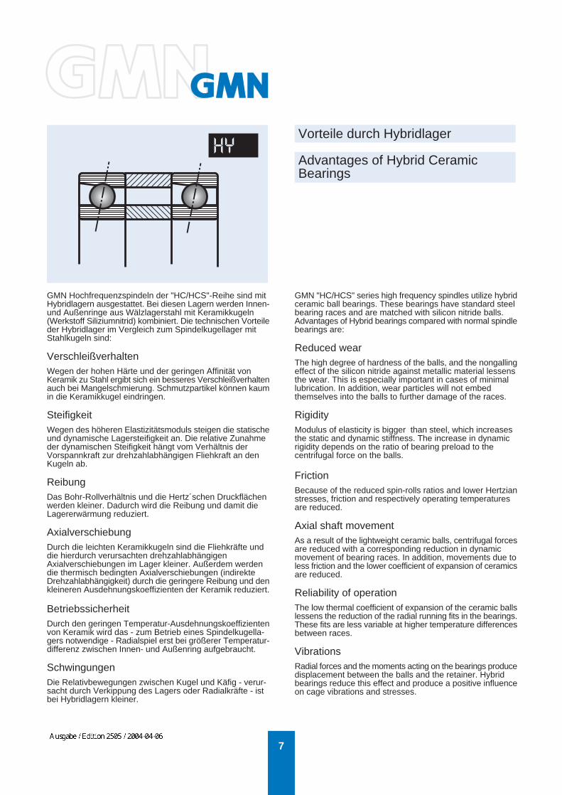
GMN Hochfrequenzspindeln der "HC/HCS"-Reihe sind mitHybridlagern ausgestattet. Bei diesen Lagern werden Innen-und Außenringe aus Wälzlagerstahl mit Keramikkugeln(Werkstoff Siliziumnitrid) kombiniert. Die technischen Vorteileder Hybridlager im Vergleich zum Spindelkugellager mitStahlkugeln sind:
VerschleißverhaltenWegen der hohen Härte und der geringen Affinität vonKeramik zu Stahl ergibt sich ein besseres Verschleißverhaltenauch bei Mangelschmierung. Schmutzpartikel können kaumin die Keramikkugel eindringen.
SteifigkeitWegen des höheren Elastizitätsmoduls steigen die statischeund dynamische Lagersteifigkeit an. Die relative Zunahmeder dynamischen Steifigkeit hängt vom Verhältnis derVorspannkraft zur drehzahlabhängigen Fliehkraft an denKugeln ab.
ReibungDas Bohr-Rollverhältnis und die Hertz´schen Druckflächenwerden kleiner. Dadurch wird die Reibung und damit dieLagererwärmung reduziert.
AxialverschiebungDurch die leichten Keramikkugeln sind die Fliehkräfte unddie hierdurch verursachten drehzahlabhängigenAxialverschiebungen im Lager kleiner. Außerdem werdendie thermisch bedingten Axialverschiebungen (indirekteDrehzahlabhängigkeit) durch die geringere Reibung und denkleineren Ausdehnungskoeffizienten der Keramik reduziert.
BetriebssicherheitDurch den geringen Temperatur-Ausdehnungskoeffizientenvon Keramik wird das - zum Betrieb eines Spindelkugella-gers notwendige - Radialspiel erst bei größerer Temperatur-differenz zwischen Innen- und Außenring aufgebraucht.
SchwingungenDie Relativbewegungen zwischen Kugel und Käfig - verur-sacht durch Verkippung des Lagers oder Radialkräfte - istbei Hybridlagern kleiner.
GMN "HC/HCS" series high frequency spindles utilize hybridceramic ball bearings. These bearings have standard steelbearing races and are matched with silicon nitride balls.Advantages of Hybrid bearings compared with normal spindlebearings are:
Reduced wearThe high degree of hardness of the balls, and the nongallingeffect of the silicon nitride against metallic material lessensthe wear. This is especially important in cases of minimallubrication. In addition, wear particles will not embedthemselves into the balls to further damage of the races.
RigidityModulus of elasticity is bigger than steel, which increasesthe static and dynamic stiffness. The increase in dynamicrigidity depends on the ratio of bearing preload to thecentrifugal force on the balls.
FrictionBecause of the reduced spin-rolls ratios and lower Hertzianstresses, friction and respectively operating temperaturesare reduced.
Axial shaft movementAs a result of the lightweight ceramic balls, centrifugal forcesare reduced with a corresponding reduction in dynamicmovement of bearing races. In addition, movements due toless friction and the lower coefficient of expansion of ceramicsare reduced.
Reliability of operationThe low thermal coefficient of expansion of the ceramic ballslessens the reduction of the radial running fits in the bearings.These fits are less variable at higher temperature differencesbetween races.
VibrationsRadial forces and the moments acting on the bearings producedisplacement between the balls and the retainer. Hybridbearings reduce this effect and produce a positive influenceon cage vibrations and stresses.
WEHRFRIT
Ausgabe / Edition 2505 / 2004-04-06

8
Dies wirkt sich auf die Käfigbeanspruchung undUnwuchtschwingungen des Kugelsatzes(Käfigumlauffrequenz) günstig aus.
ErmüdungslebensdauerWenn die Hertz´sche Flächenspannung in den Kontaktstel-len zwischen Kugel und Ring gleich ist, kann für Stahl- undHybridlager von einer vergleichbaren Ermüdungslebensdau-er ausgegangen werden. Vorteile für das Hybridlager erge-ben sich hier bei hohen Drehzahlkennwerten.
GenauigkeitIn den Spindeln der HC-Familie werden grundsätzlich Kugel-lager der Genauigkeitsklasse nach GMN Werknorm UPverwendet. Diese zeichnen sich im Vergleich zu internationa-len Normen durch höchste Laufgenauigkeiten aus:
Rundlauf des Innenrings am zusammengebauten Lager -Radialschlag in µm
Bohrungsdurch- Genauigkeitsklassemesser [mm] P4/ABEC 7 P2/ABEC 9 UP
> 2,5..10 2,5 1,5 1,5> 10...18 2,5 1,5 1,5> 18...30 3,0 2,5 1,5> 30...50 4,0 2,5 2,0> 50...80 4,0 2,5 2,0
Planlauf der Stirnseite, bezogen auf die Laufbahn, amzusammengebauten Lager -
Axialschlag in µm
Außendurch- Genauigkeitsklassemesser [mm] P4/ABEC 7 P2/ABEC 9 UP
> 6... 8 5,0 1,5 2,0> 18... 30 5,0 2,5 2,0> 30... 50 5,0 2,5 2,0> 50... 80 5,0 4,0 3,0> 80...120 6,0 5,0 3,0
Unsere Spindeln können auch mit Hybridlagern geliefertwerden, deren Ringe aus dem Werkstoff "Cronidur"hergestellt sind.Dies bietet größere Betriebssicherheit und ermöglichthöhere Drehzahlkennwerte, vor allem bei Fettdauer-schmierung.
Fatique life
The fatique life is comparable when the Hertzian stress onthe contact surfaces between rings and balls is similar.As a result of the minor weight of the ceramic balls the Hertzianstress is lower.Therefore hybrid bearings achieve longer life time.
AccuracySpindles of HC family are fitted with bearings producedaccording to GMN standard grade UP. They are distinguishedfrom international standards due to excellent running accuracy.
Radial runout of assembled bearing inner ringLimits in micron
Bearing bore Tolerance classdiameter [mm] P4/ABEC 7 P2/ABEC 9 UP
> 2,5..10 2,5 1,5 1,5> 10...18 2,5 1,5 1,5> 18...30 3,0 2,5 1,5> 30...50 4,0 2,5 2,0> 50...80 4,0 2,5 2,0
Assembled bearing outer ring face runout with racewayaxial runout - Limits in micron
Bearing outside Tolerance classdiameter [mm] P4/ABEC 7 P2/ABEC 9 UP
> 6... 8 5,0 1,5 2,0> 18... 30 5,0 2,5 2,0> 30... 50 5,0 2,5 2,0> 50... 80 5,0 4,0 3,0> 80...120 6,0 5,0 3,0
Our spindles can also be supplied with "Cronidur ceramicbearings". The rings are made of Cronidur and the ballsfrom ceramic.This offers improved reliability and enables higher speedvalues, particularly when permanently grease lubricated.
Vorteile durch Hybridlager
Advantages of Hybrid Ceramic Bearings
WEHRFRIT
Ausgabe / Edition 2505 / 2004-04-06

9
die Werkzeugaufnahme
Tool interface
GMN Hochfrequenzspindeln können mit Schnittstellen fürdie gängigen Werkzeugaufnahmen ausgestattet werden.
Bevorzugt wird die HSK-Ausführung eingesetzt, die gegen-über dem Steilkegel wesentliche Vorteile bietet:
Hohe statische und dynamische SteifigkeitHohe Wechsel- und WiederholgenauigkeitGeringe axiale Veränderung bei DrehzahländerungVerstärkung der Einzugskraft bei Drehzah-steigerungHohe DrehmomentübertragungReduziertes Gefahrenpotential durch innenliegende Mitnehmer (Form A/C).
"Kegel-Hohlschäfte mit Plananlage" sind nach DIN 69893genormt. Die verschiedenen Varianten der Teilefamiliebesitzen einheitlich den gleichen Schaft. Der Bund ist derjeweiligen Anwendung angepaßt.
In den Spindeln der Reihe HC/HCS ... können je nachKonstruktion Werkzeuge mit Hohlschäften der Form A/C, Eoder F aufgenommen werden.
Die Form E weist keine Aussparungen für die Momenten-übertragung durch Mitnehmer auf. Das Drehmoment wirdausschließlich kraftschlüssig übertragen. Sie wurde vor-zugsweise für hohe Drehzahlen entwickelt.
Die Form A/C kann auch für den manuellen Wechsel bei derHSP-Reihe verwendet werden. Dadurch ist oftmals eineBegrenzung der Werkzeugvielfalt möglich.
Werkzeuge mit Hohlschäften der Form B/D können in denGMN Spindeln des Typs HC/HCS... nicht verwendet werden.Sie sind für andere Anwendungen konzipiert.
GMN can provide high frequency spindles to accept commontooling interface configurations.
The prefered HSK style offers the following advantagesversus the ISO taper:
High static and dynamic rigidityHigh tool change accuracy and repeatabilityLow axial movement during speed variationsIncreased pull-in force as the speed increasesHigh torque transmissionIncrease in personal safety due to the internaldrive dogs (Form A/C).
"Hollow tapered shanks with flat contact surfaces" arestandard per DIN 69893. The different "FORMS" of a particularsize are based on a similar shank size dimension. The toolflange is dictated by the mode of tool change.
HC/HCS style spindles allow the use of tools with hollowshanks, type A/C, E or F according to interface design.
Form E was developed for high speed without drive dogs.The torque transmission is actuated by adherence.
Form A/C can also be used with manual tool change systemprovided in the HSP style spindles. This reduces the needfor additional tool holders.
Tools according to Form B/D cannot be used in the HC/HCSspindle, they are designed for different applications.
WEHRFRIT
Ausgabe / Edition 2505 / 2004-04-06
10
das Werkzeugspannsystem
Clamping systems
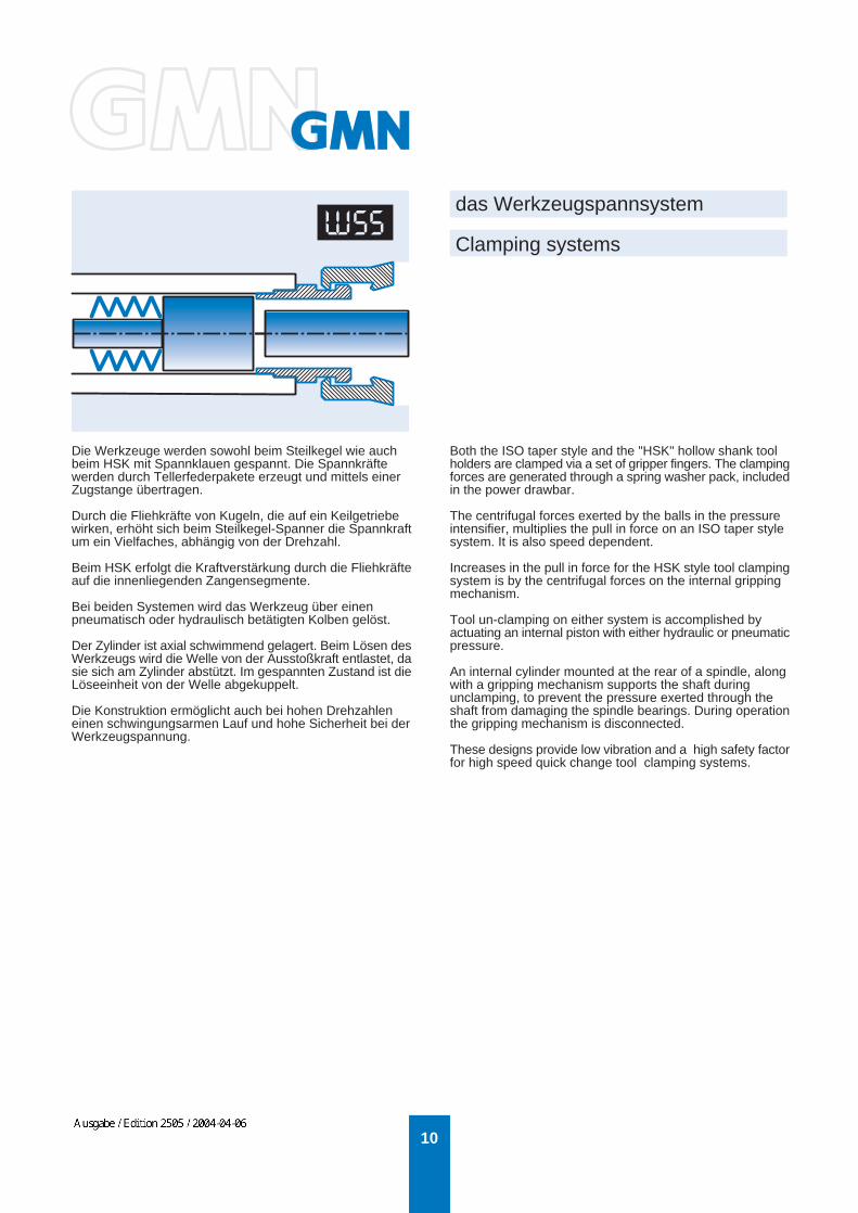
Die Werkzeuge werden sowohl beim Steilkegel wie auchbeim HSK mit Spannklauen gespannt. Die Spannkräftewerden durch Tellerfederpakete erzeugt und mittels einerZugstange übertragen.
Durch die Fliehkräfte von Kugeln, die auf ein Keilgetriebewirken, erhöht sich beim Steilkegel-Spanner die Spannkraftum ein Vielfaches, abhängig von der Drehzahl.
Beim HSK erfolgt die Kraftverstärkung durch die Fliehkräfteauf die innenliegenden Zangensegmente.
Bei beiden Systemen wird das Werkzeug über einenpneumatisch oder hydraulisch betätigten Kolben gelöst.
Der Zylinder ist axial schwimmend gelagert. Beim Lösen desWerkzeugs wird die Welle von der Ausstoßkraft entlastet, dasie sich am Zylinder abstützt. Im gespannten Zustand ist dieLöseeinheit von der Welle abgekuppelt.
Die Konstruktion ermöglicht auch bei hohen Drehzahleneinen schwingungsarmen Lauf und hohe Sicherheit bei derWerkzeugspannung.
Both the ISO taper style and the "HSK" hollow shank toolholders are clamped via a set of gripper fingers. The clampingforces are generated through a spring washer pack, includedin the power drawbar.
The centrifugal forces exerted by the balls in the pressureintensifier, multiplies the pull in force on an ISO taper stylesystem. It is also speed dependent.
Increases in the pull in force for the HSK style tool clampingsystem is by the centrifugal forces on the internal grippingmechanism.
Tool un-clamping on either system is accomplished byactuating an internal piston with either hydraulic or pneumaticpressure.
An internal cylinder mounted at the rear of a spindle, alongwith a gripping mechanism supports the shaft duringunclamping, to prevent the pressure exerted through theshaft from damaging the spindle bearings. During operationthe gripping mechanism is disconnected.
These designs provide low vibration and a high safety factorfor high speed quick change tool clamping systems.
WEHRFRIT
Ausgabe / Edition 2505 / 2004-04-06

11
Positionssensoren
Position sensors
Verschiedene Sensoren in und an der Spindel ermöglicheneinen störungsfreien und sicheren Betriebsablauf.
WerkzeugwechselJe nach Spindelausführung, d. h. Größe undNenndrehzahl, können verschiedene Sensorenangebaut werden, die Informationen für die Steuerungdes Werkzeugwechsels liefern.
Variante AMit zwei Endschaltern wird die Position des Werkzeug-Lösekolbens erfaßt, welche die Signale "Kolbenvorne" und "Kolben hinten" liefern.
Variante BBei ausreichendem Wellendurchmesser kann diePosition der Zugstange, welche das Werkzeug spannt,durch induktive Näherungsschalter oder einenAnalogsensor direkt kontrolliert werden. Damit stehen die Signale "Werkzeug gespannt","Werkzeug gelöst" und "gespannt ohne Werkzeug"zur Verfügung.
Variante CDie Einrichtung "Kegel reinigen" ermöglicht es, denLuftdurchsatz zu überwachen. Bei gespanntemWerkzeug muß die Schnittstelle abgedichtet sein. DerVorteil dieser Konstruktion besteht darin, daß aucherkannt wird, wenn Werkzeuge falsch gespannt sind.Nachteilig ist, daß die Werkzeugwechselzeitenverlängert werden.
Rotation der WelleKann wegen der Abmessungen oder der Nenndrehzahlen kein Drehwinkelgeber verwendetwerden, so ist es möglich, über einen Impulsgebermit entsprechendem Verstärker die Signale"Solldrehzahl erreicht" und "Welle steht" zu erhalten.
The GMN spindles are equipped with proximity sensorsto allow for proper, trouble free operation during toolchanging.
Tool changeDepending on the size and nominal speed of thespindle, a variety of sensor arrangements can beapplied for feed back to the machine control, aboutthe tool changing cycle.
Variation AA (2) two sensor arrangement for monitor the positionof the piston, either "forward" or "back".
Variation BDepending on the internal space constraints thedrawbar can be monitored for "tool clamped","unclamped", "clamped no tool", with (3) inductiveproximity switches or one analog sensor.
Variation CBy utilizing the "taper cleaning" feature the air flowcan also provide a signal that tool is improperly sizedor not clamped correctly. This method can increasetool changing times.
Rotation of shaftIf the spindle size and speed restrict the use of anencoder, GMN can provide alternative sensors foractual shaft speed, and also "zero speed".
WEHRFRIT
Ausgabe / Edition 2505 / 2004-04-06

12
SS
M M
Drehwinkelgeber für feldorientierte Regelung
Integral encoders for closed loop control
Hochauflösende Lagegeber in den Spindeln erfassen zujeder Zeit Ist-Drehzahl und genaue Winkel-Position der Welle.
Dies bietet folgende Vorteile:auch bei niedrigen Drehzahlen eine gleichmäßige Drehbewegung der WelleC-Achsbetrieb, u. a. mit der Möglichkeit zum Gewindeschneiden ohne Längsausgleich-VorrichtungPositionierung der Welle mit hoher Genauigkeit- im Bereich von 0,001 Graddurch gutes Führungs- und Lastverhalten Betrieb ander Leistungsgrenze des Antriebssystems und damitkurze Beschleunigungs- und Bremszeiten.Das Leistungsvermögen des Motors kann vollständigausgenutzt werden.
Für die unterschiedlichen Antriebs-Fabrikate können geeigneteAufnehmer in die Spindel eingebaut werden.Der Drehwinkelgeber besteht aus einem Meßrad auf derWelle und einem Sensor, welcher servicefreundlich imSpindelgehäuse eingebaut ist.
Auf einem Leistungsprüfstand im Hause GMN werdenLeistung von Spindel + Antrieb gemessen und die Parameterfür die jeweiligen Anforderungen ermittelt und optimiert.
Incorporating high resolution encoders into spindles, providesfeedback and control of the actual shaft speed, and angularposition of the shaft, at all times.
The advantages are as follows:Smooth precise rotation and control at low speed"C"-axis operation e. g. thread whirlingShaft positioning within 0.001 degreeThe drives high dynamic performance at full capacity,combined with the quick acceleration and decelerationtimes, allows the systems full power capacity to be utilized.
GMN can interface the encoders to meet the selected drivesystems requirements.
The encoder system consists of a precision gear mountedto the rotating spindle shaft and a stationary sensor in thespindle housing readily accessible, for ease of service.
GMN will optimize the performance of the complete spindleand drive package before shipment, and provide all thenecessary parameters.
Motor
Drehwinkel-geber DWG
Leistungs-
leitung
Signal-
leitung
Anzeige
Bedienfeld
Antriebsmodul
mit
Regelung
RS 232 C-Schnittstelle
EncoderDWG
Power
leads
Signal-
leads
Digital display
Programmablekeypad
Drive modulewith
field-orientedclosed-loop
control system
RS 232 C-interface
Motor
WEHRFRIT
Ausgabe / Edition 2505 / 2004-04-06

13
SP
FR
Um zu verhindern, dass während des Betriebs Kühlmitteloder Schmutz in die Spindel eindringt, wird in derStandardausführung eine Sperrluftabdichtung verwendet.Dabei strömt kontinuierlich Luft aus einem Ringspaltzwischen Welle und Gehäuse.Bei Öl-Luft-Schmierung verhindert die Luftströmung auch,dass das verbrauchte Schmiermittel am Wellenspalt aus-tritt.
Sperrluftabdichtung
Air purge
Fluid-Ring-Dichtung
Fluid-ring seal
Eine andere Möglichkeit der Abdichtung ist die Ver-wendung der patentierten Fluid-Ring-Dichtung.Die Spindel ist ohne Druckluft jederzeit abgedichtet.
Pressurized air is used to prevent the ingress ofcontamination into the bearing system. A continuous flowof clean dry air fills the closely machined gaps betweenthe stationary and rotating members of the spindle. The airstream also stops the spent oil lubrication from existing atthe front of the spindle and away from the work piece.
GMN has patented a “Fluid Ring“ seal which can beincorporated in most GMN spindle designs, can operate inheavy external coolant and dust conditions, is NO speedlimitations, and requires NO air.
WEHRFRIT
Ausgabe / Edition 2505 / 2004-04-06
14
Kegelreinigen
Innere Kühlmittel-Zuführung
Taper cleaning
Coolant through shaft
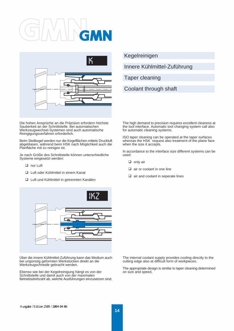
Die hohen Ansprüche an die Präzision erfordern höchsteSauberkeit an der Schnittstelle. Bei automatischenWerkzeugwechsel-Systemen sind auch automatischeReingigungsverfahren erforderlich.
Beim Steilkegel werden nur die Kegelflächen mittels Druckluftabgeblasen, während beim HSK nach Möglichkeit auch diePlanfläche mit zu reinigen ist.
Je nach Größe des Schnittstelle können unterschiedlicheSysteme eingesetzt werden:
nur Luft
Luft oder Kühlmittel in einem Kanal
Luft und Kühlmittel in getrennten Kanälen
Über die innere Kühlmittel-Zuführung kann das Medium auchbei ungünstig geformten Werkstücken direkt an dieWerkzeugschneide gebracht werden.
Ebenso wie bei der Kegelreinigung hängt es von derSchnittstelle und damit auch von der maximalenBetriebsdrehzahl ab, welche Ausführungen einzusetzen sind.
The high demand to precision requires excellent cleaness atthe tool interface. Automatic tool changing system call alsofor automatic cleaning systems.
ISO taper cleaning can be operated at the taper surfaceswhereas the HSK request also treatment of the plane facewhen the size it accepts.
In accordance to the interface size different systems can beused:
only air
air or coolant in one line
air and coolant in seperate lines
The internal coolant supply provides cooling directly to thecutting edge also at difficult form of workpieces.
The appropriate design is similar to taper cleaning determinedon size and speed.
WEHRFRIT
Ausgabe / Edition 2505 / 2004-04-06

15
M
Kühlmittel durch Gehäuse
Coolant through spindle housing
Zur Kühlung von Werkzeug und Werkstück wird dasMedium durch das Spindelgehäuse und Düsen an dieBearbeitungsoberfläche gebracht.
Als Medium kann Druckluft, Kühlschmiermittel/Luft-Gemisch oder Kühlschmiermittel verwendet werden.
For cooling of tool and workpiece the medium is suppliedthrough spindle housings and nozzels to the cuttingsurfaces.
Compressed air, cooling lubricant/air mixture or coolinglubricant can be used.
GelenkdüseAdjustable nozzle
Darstellung mit Kühlschmiermittelals Medium
Representation with cooling lubricantas medium
WEHRFRIT
Ausgabe / Edition 2505 / 2004-04-06

16
Einstellbare Lagervorspannung
Adjustable bearing preload
Lageranordnung und Vorspannung bestimmen die Steifig-keit der Spindel und beeinflußen die Lebensdauer derWälzlager.
Für kleine Drehzahlbereiche, vor allem bei niedrigenDrehzahlen, sind die verschiedenen Varianten der starrenAbstimmung geeignet. Hohe Drehzahlen bzw. große Dreh-zahlbereiche erfordern Systeme, bei welchen die Vor-spannung durch Erwärmung und Drehzahlsteigerung nichtwesentlich erhöht wird. Hier hat sich die Federvorspannungbewährt.Beide Anordnungen haben den Nachteil, daß sich die Vor-spannung von außen nicht verändern läßt.
Das System "Einstellbare Lagervorspannung" ermöglicht,die Lagervorspannung der Bearbeitungsaufgabe unterBerücksichtigung der Lebensdauer anzupassen.
Die Lager sind mit einem Mindestwert durch Federn vor-gespannt. Über einen Hydraulikkolben wird mittels variablemDruck der optimale Vorspannungswert eingestellt.
Außerdem wurde festgestellt, daß die Schwingungen durchdieses System gedämpft werden.
Bearing arrangement and preload determine the rigidity, andinfluence the life time of the spindle system.
For small speed ranges, and low speed operation the differentversions of a solid preload arrangement are suitable.
Large speed range variances, and high speed spindles,require a systems that will not allow the bearing preload tobe influenced by either temperature or speed.These applications require spring preloading of the bearings.
The above mentioned arrangements cannot be adjusted orchanged, without disassembling the spindle.
With the"Adjustable bearing preload" system the bearingpreload can be optimized to the application, and prolong thelifetime of the spindle.
The base preload of the bearings is determined by the highestspeed requirements, and is set by spring preloading.The optimized settings over the speed range is varied throughan internal piston which is actuated via either hydraulic orpneumatic pressure.
As further advantage of the adjustable preload system isreduction of vibration.
WEHRFRIT
Ausgabe / Edition 2505 / 2004-04-06

17
°C
Temperaturmessung am Außenring des vorderen Lagers
A methode for controlling axial shaft growth
Für die Präzisionsbearbeitung muß die Lage derWerkzeugschneide in einer definierten Lage gehalten werden.Eine axiale Verlagerung der Wellenplanfläche wird durchTemperaturveränderungen und Fliehkräfte an den Kugelnverursacht.
axiale Verschiebung axial movement
Die Komponente "Fliehkräfte" kann berechnet und diedrehzahlabhängige Verlagerung durch die Maschinen-steuerung kompensiert werden.
Ein direktes Messen der Temperatur an der Welle ist wegender hohen Drehzahlen aufwendig. Es hat sich aber gezeigt,daß die konstruktiv einfacher meßbare Temperatur amAußenring des vorderen Lagers eine ausreichend genaueFührungsgröße zum Ausgleich der Verlagerung darstellt.
Precision machining requires the position of the cutting edgeof the tool to be maintained. Temperature variations andcentrifugal forces at the balls and bearing races, can causeaxial movement of the tool mounting face of the shaft.
The "centrifugal forces" factor can be calculated and thespeed dependent shaft movement can be compensated bythrough the machine tool control.
Measuring the shaft temperature at the bearing duringoperation is difficult.Experience has shown that by measuring the temperature atouter diameter of the bearings, approximate temperaturevariations can be established and the axial movementcompensated for.
WEHRFRIT
Ausgabe / Edition 2505 / 2004-04-06
18
axiale Verschiebungaxial movement
0
5
10
15
20
25
30
35
40
0 5 10 15 20 25 30 35 40 45 50 55 60
Tem
per
atu
r [°
C]
Axi
ale
Ver
lag
eru
ng
[µ
m]
Zeit [min]
KühlmittelzufuhrKühlmittelabfuhrKugellagertemperatur
Drehzahl 25000 min-1
0
5
10
15
20
25
30
35
40
0 5 10 15 20 25 30 35 40 45 50 55 60
Tem
per
atu
re [
°C]
Axi
al d
isp
lace
men
t [µ
m]
Time [min]
Coolant inletCoolant outletBearing temperatur
Speed 25000 rpm
VerlagerungMotortemperatur
DisplacementMotor temperature
0
5
10
15
20
25
30
35
40
0
5
10
15
20
25
30
35
40
Messung der axialen Wellenver- lagerung mittels Sensor
Measurement of the axial shaft growth by sensor
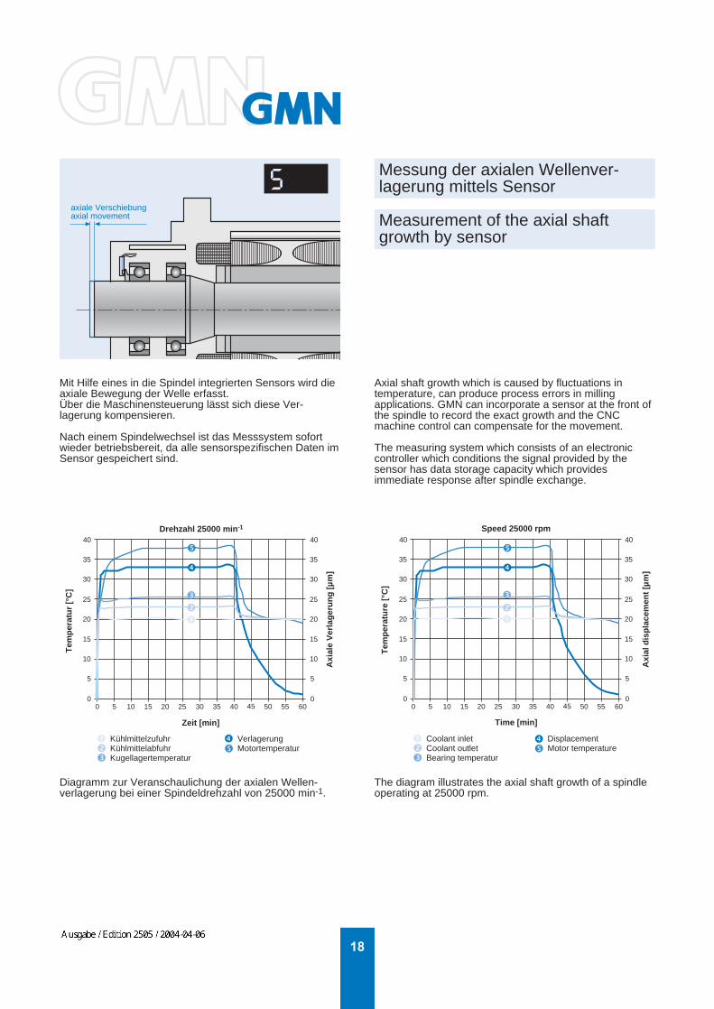
Mit Hilfe eines in die Spindel integrierten Sensors wird dieaxiale Bewegung der Welle erfasst.Über die Maschinensteuerung lässt sich diese Ver-lagerung kompensieren.
Nach einem Spindelwechsel ist das Messsystem sofortwieder betriebsbereit, da alle sensorspezifischen Daten imSensor gespeichert sind.
Axial shaft growth which is caused by fluctuations intemperature, can produce process errors in millingapplications. GMN can incorporate a sensor at the front ofthe spindle to record the exact growth and the CNCmachine control can compensate for the movement.
The measuring system which consists of an electroniccontroller which conditions the signal provided by thesensor has data storage capacity which providesimmediate response after spindle exchange.
Diagramm zur Veranschaulichung der axialen Wellen-verlagerung bei einer Spindeldrehzahl von 25000 min-1.
The diagram illustrates the axial shaft growth of a spindleoperating at 25000 rpm.
WEHRFRIT
Ausgabe / Edition 2505 / 2004-04-06
19
5
0
10
15
01000
20003000
40005000 0
2
4
6
8
10
Am
plitu
de [µ
m]
Frequenz [Hz]
ap [mm]
Quelle:
5
0
10
15
01000
20003000
40005000 0
2
4
6
8
10
Am
plitu
de [µ
m]
Frequency [Hz]
ap [mm]
Source:
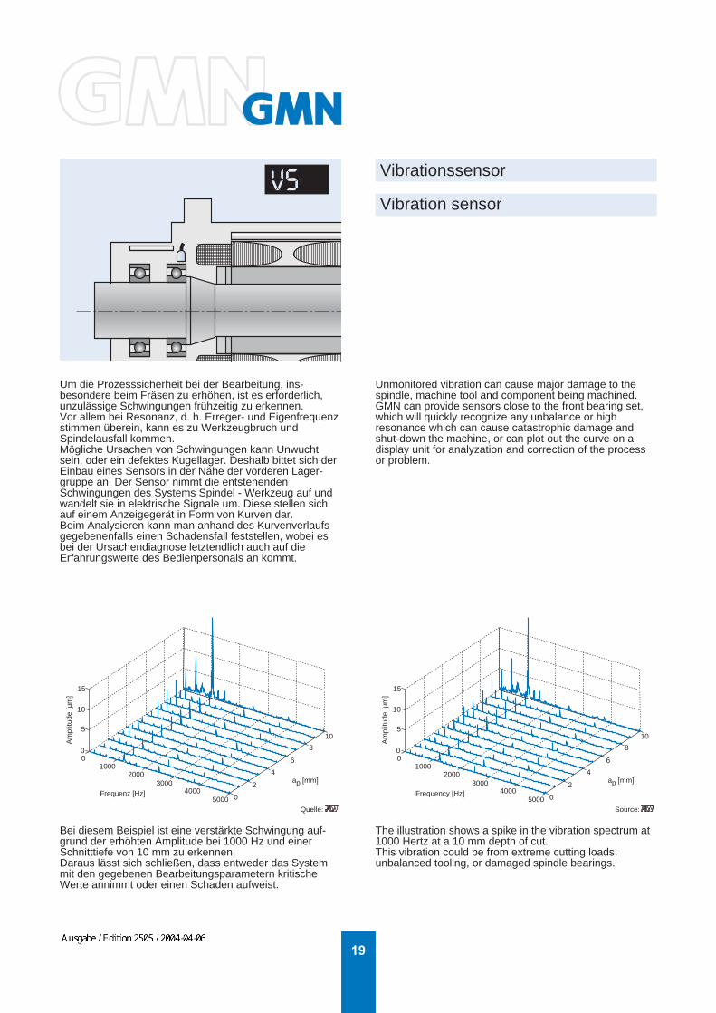
Um die Prozesssicherheit bei der Bearbeitung, ins-besondere beim Fräsen zu erhöhen, ist es erforderlich,unzulässige Schwingungen frühzeitig zu erkennen.Vor allem bei Resonanz, d. h. Erreger- und Eigenfrequenzstimmen überein, kann es zu Werkzeugbruch undSpindelausfall kommen.Mögliche Ursachen von Schwingungen kann Unwuchtsein, oder ein defektes Kugellager. Deshalb bittet sich derEinbau eines Sensors in der Nähe der vorderen Lager-gruppe an. Der Sensor nimmt die entstehendenSchwingungen des Systems Spindel - Werkzeug auf undwandelt sie in elektrische Signale um. Diese stellen sichauf einem Anzeigegerät in Form von Kurven dar.Beim Analysieren kann man anhand des Kurvenverlaufsgegebenenfalls einen Schadensfall feststellen, wobei esbei der Ursachendiagnose letztendlich auch auf dieErfahrungswerte des Bedienpersonals an kommt.
Vibrationssensor
Vibration sensor
Bei diesem Beispiel ist eine verstärkte Schwingung auf-grund der erhöhten Amplitude bei 1000 Hz und einerSchnitttiefe von 10 mm zu erkennen.Daraus lässt sich schließen, dass entweder das Systemmit den gegebenen Bearbeitungsparametern kritischeWerte annimmt oder einen Schaden aufweist.
Unmonitored vibration can cause major damage to thespindle, machine tool and component being machined.GMN can provide sensors close to the front bearing set,which will quickly recognize any unbalance or highresonance which can cause catastrophic damage andshut-down the machine, or can plot out the curve on adisplay unit for analyzation and correction of the processor problem.
The illustration shows a spike in the vibration spectrum at1000 Hertz at a 10 mm depth of cut.This vibration could be from extreme cutting loads,unbalanced tooling, or damaged spindle bearings.
WEHRFRIT
Ausgabe / Edition 2505 / 2004-04-06

20
MischkammerMixing chamber
Merkmale der Einkanal-Minimalmengensschmierung:
- sehr feiner Ölnebel (Aerosol)- Drehzahlbegrenzung wegen Aerosol-Entmischung- für Standard-Drehdurchführungen- für Werkzeuge mit Kühlkanaldurchmesser > 1 mm- längere Reaktionszeiten bei Mengenänderungen als
beim Zweikanalsystem- für Maschinen mit wenig Werkzeugwechseln
Characteristics of single-channel minimized coolantsupply:
- superfine oil mist (aerosol)- speed limitation due to aerosol decomposition- for standard rotary unions- for tools with coolant bore diameter > 1 mm- in comparison with two-channel system longer reaction times at quantity changings- for machines with less tool changes
Schema der Schmiermittel-aufbereitung
Lubrication schematic
Interne Minimalmengenschmierung Einkanalsystem
Internal minimized coolant supply Single-channel system
WEHRFRIT
Ausgabe / Edition 2505 / 2004-04-06

21
MischkopfMixing head
Merkmale der Zweikanal-Minimalmengenschmierung:
- kein Ölnebel- Öl und Luft in fast beliebigen Mengen mischbar oder nur Zufuhr von Luft- höhere Drehzahlen als bei Einkanalsystem möglich- für Werkzeuge mit Kühlkanaldurchmesser < 1 mm- für Werkzeuge mit hohem Schmierstoffbedarf- für Maschinen mit mehr Werkzeugwechseln
Characteristics of two-channel minimized coolantsupply:
- no oil mist- oil and air mixable in almost any quantities or only air supply- in comparison with single-channel system higher speeds possible- for tools with high lubricant consumption- for machines with more tool changes
Schema der Schmiermittel-aufbereitung
Lubrication schematic
Interne Minimalmengenschmierung Zweikanalsystem
Internal minimized coolant supply Two-channel system
WEHRFRIT
Ausgabe / Edition 2505 / 2004-04-06

22
Schnell-Kupplung * Multi-Kupplung
Quick Couplings * Multi Couplings
GMN Spindeln können mit Multikupplungen für dieVersorgung mit Energie und Betriebsstoffen geliefert werden.
Dies verkürzt die unproduktiven Spindel-Wechselzeiten oderermöglicht - bei entsprechender Gestaltung - sogar dasautomatische Wechseln von Spindeln und erhöht damit dieFlexiblität der Maschine.
GMN spindles can be supplied with multi-couplings for energyand fuel supply.
This reduces the unproductive spindle replacement times,or - depending on the design - can even make possible theautomatic replacement of spindles, thus increasing theflexibility of the machine.
WEHRFRIT
Ausgabe / Edition 2505 / 2004-04-06

23
(17,5)
7,5
2
E. M. 6,5 +0,180
h5
79,8
-0,1
79,9
-0,1
2857
• nmax 40000 1/min• ATC HSK-E 25• P (S1) 2,2 kW bei 40000 1/min• M (S1) 0,53 Nm• Für gesteuerten Antrieb
• Fett-Dauerschmierung• Hybridlager in Hochpräzisionsausführung• Bohrung der vorderen Lager 30 mm• Sperrluftabdichtung• Kegelreinigung der Werkzeugaufnahme mittels Luft• Überwachung der Werkzeugaufnahme
"gespannt", "gelöst"mit einem Analogsensor
• Hydraulische oder pneumatische Löseeinheit
• Radiale Steifigkeit 89 N/µm• Axiale Steifigkeit 120 N/µm
• nmax 40000 rpm• ATC HSK-E 25• P (S1) 2.2 kW at 40000 rpm• M (S1) 0.53 Nm• For open-loop drive
• Permanent grease lubrication• High precision hybrid ceramic bearings• Bore of front bearings 30 mm• Air purge• Taper cleaning of tool interface by air• Monitoring of tool interface
"clamped", "unclamped"by one analog sensor
• Hydraulic or pneumatic unclamp unit
• Radial rigidity 89 N/µm• Axial rigidity 120 N/µm
EinspannlängeLocating length 112
Hydraulikausführung Hydraulic execution 299
Pneumatikausführung Pneumatic execution 361
Drehzahl n [1/min] / Speed n [rpm]
LeistungPowerP [kW]
Drehzahl n [1/min] / Speed n [rpm]
DrehmomentTorqueM [Nm]
HC 80cg - 40000/2,2
P S1P S6-60%P S6-40%
M S1
M S6-60%
M S6-40%
0
0,5
1
1,5
2
2,5
3
0 8000 16000 24000 32000 400000
0,1
0,2
0,3
0,4
0,5
0,6
0,7
0 8000 16000 24000 32000 40000
WEHRFRIT
Ausgabe / Edition 2505 / 2004-04-06

24
HCS 100cg - 40000/3,9
70
105
105
162,5 103 15
435
1,9
17,510
44
82 28
57
• nmax 40000 rpm• ATC HSK-E 25• P (S1) 3.9 kW at 9710 rpm• M (S1) 3.8 Nm• Encoder for closed-loop drive
~ 1 VSS, 150 cycles/rev.
• Permanent grease lubrication• High precision hybrid ceramic bearings• Bore of front bearings 30 mm• Air purge• Monitoring of tool interface
"clamped", "unclamped"• Static tool pull-in force 2.8 kN
• Radial rigidity 36 N/µm• Axial rigidity 50 N/µm
• nmax 40000 1/min• ATC HSK-E 25• P (S1) 3,9 kW bei 9710 1/min• M (S1) 3,8 Nm• Encoder für geregelten Antrieb
~ 1 VSS, 150 Impulse/Umdrehung
• Fett-Dauerschmierung• Hybridlager in Hochpräzisionsausführung• Bohrung der vorderen Lager 30 mm• Sperrluftabdichtung• Überwachung der Werkzeugaufnahme
"gespannt", "gelöst"• Statische Werkzeugeinzugskraft 2,8 kN
• Radiale Steifigkeit 36 N/µm• Axiale Steifigkeit 50 N/µm
DrehmomentTorqueM [Nm]
LeistungPowerP [kW]
Drehzahl n [1/min] / Speed n [rpm] Drehzahl n [1/min] / Speed n [rpm]
0
1
2
3
4
5
6
0 8000 16000 24000 32000 400000
1
2
3
4
5
6
0 8000 16000 24000 32000 40000
P S1
P S6-60%
P S6-40%
M S1
M S6-60%
M S6-40%
WEHRFRIT
Ausgabe / Edition 2505 / 2004-04-06

25
HC 120 - 42000/11
3
6 1448,5
400
554,5
68 ca. 86,5
119,
9 -0,
1
100
38 120 h
5
119,
7 -0,
1
• nmax 42000 1/min• ATC HSK-E 40 oder ISO Kegel SK 30 ohne Nutensteine• P (S1) 11 kW bei 30000 1/min• M (S1) 3,5 Nm• Für gesteuerten Antrieb
• Öl-/Luftschmierung• Hybridlager in Hochpräzisionsausführung• Bohrung der vorderen Lager 45 mm• Sperrluftabdichtung• Kegelreinigung der Werkzeugaufnahme mittels Luft• Überwachung der Werkzeugaufnahme
"gespannt", "gelöst"• Statische Werkzeugeinzugskraft 5 kN
• Radiale Steifigkeit 173 N/µm• Axiale Steifigkeit 90 N/µm
• nmax 42000 rpm• ATC HSK-E 40 or ISO taper SK 30 without drive dogs• P (S1) 11 kW at 30000 rpm• M (S1) 3.5 Nm• For open-loop drive
• Oil/air lubrication• High precision hybrid ceramic bearings• Bore of front bearings 45 mm• Air purge• Taper cleaning of tool interface by air• Monitoring of tool interface
"clamped", "unclamped"• Static tool pull-in force 5 kN
• Radial rigidity 173 N/µm• Axial rigidity 90 N/µm
Drehzahl n [1/min] / Speed n [rpm]
LeistungPowerP [kW]
DrehmomentTorqueM [Nm]
Drehzahl n [1/min] / Speed n [rpm]
EinspannlängeLocating length
Stecker - ÜberwachungConnector - Monitoring
Stecker - MotorConnector - Motor
229
0
2
4
6
8
10
12
14
0 6000 12000 18000 24000 30000 36000 42000
P S1
P S6-60%
P S6-40%
0
0,5
1
1,5
2
2,5
3
3,5
4
4,5
0 6000 12000 18000 24000 30000 36000 42000
M S1
M S6-60%
M S6-40%
WEHRFRIT
Ausgabe / Edition 2505 / 2004-04-06
26
HC 120 - 50000/11
5
7,5 48,4 14
481
68
119,
9
58 38,5
99,8
120 h
5
119,
7
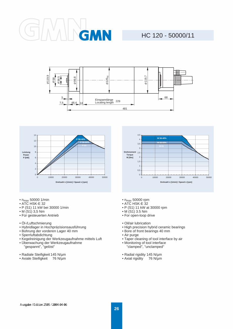
• nmax 50000 1/min• ATC HSK-E 32• P (S1) 11 kW bei 30000 1/min• M (S1) 3,5 Nm• Für gesteuerten Antrieb
• Öl-/Luftschmierung• Hybridlager in Hochpräzisionsausführung• Bohrung der vorderen Lager 40 mm• Sperrluftabdichtung• Kegelreinigung der Werkzeugaufnahme mittels Luft• Überwachung der Werkzeugaufnahme
"gespannt", "gelöst"
• Radiale Steifigkeit 145 N/µm• Axiale Steifigkeit 76 N/µm
• nmax 50000 rpm• ATC HSK-E 32• P (S1) 11 kW at 30000 rpm• M (S1) 3.5 Nm• For open-loop drive
• Oil/air lubrication• High precision hybrid ceramic bearings• Bore of front bearings 40 mm• Air purge• Taper cleaning of tool interface by air• Monitoring of tool interface
"clamped", "unclamped"
• Radial rigidity 145 N/µm• Axial rigidity 76 N/µm
Drehzahl n [1/min] / Speed n [rpm]
LeistungPowerP [kW]
Drehzahl n [1/min] / Speed n [rpm]
DrehmomentTorqueM [Nm]
EinspannlängeLocating length 229
0
2
4
6
8
10
12
14
0 10000 20000 30000 40000 50000
P S1
P S6-60%
P S6-40%
0
0,5
1
1,5
2
2,5
3
3,5
4
4,5
0 10000 20000 30000 40000 50000
M S1
M S6-60%
M S6-40%
WEHRFRIT
Ausgabe / Edition 2505 / 2004-04-06

27
HC 120 - 60000/5,5
3
5,5 40,9 14
336
448,5
68 50
99,8
-0,2
48 28,5
120 h
5
• nmax 60000 1/min• ATC HSK-E 25• P (S1) 5,5 kW bei 60000 1/min• M (S1) 0,9 Nm• Für gesteuerten Antrieb
• Öl-/Luftschmierung• Hybridlager in Hochpräzisionsausführung• Bohrung der vorderen Lager 30 mm• Sperrluftabdichtung• Kegelreinigung der Werkzeugaufnahme mittels Luft• Überwachung der Werkzeugaufnahme
"gespannt", "gelöst"• Statische Werkzeugeinzugskraft 2,8 kN
• Radiale Steifigkeit 105 N/µm• Axiale Steifigkeit 64 N/µm
• nmax 60000 rpm• ATC HSK-E 25• P (S1) 5.5 kW at 60000 rpm• M (S1) 0.9 Nm• For open-loop drive
• Oil/air lubrication• High precision hybrid ceramic bearings• Bore of front bearings 30 mm• Air purge• Taper cleaning of tool interface by air• Monitoring of tool interface
"clamped", "unclamped"• Static tool pull-in force 2.8 kN
• Radial rigidity 105 N/µm• Axial rigidity 64 N/µm
Drehzahl n [1/min] / Speed n [rpm]
LeistungPowerP [kW]
Drehzahl n [1/min] / Speed n [rpm]
DrehmomentTorqueM [Nm]
EinspannlängeLocating length 196
Motorkabel IN 604Motor cable IN 604
0
1
2
3
4
5
6
7
0 12000 24000 36000 48000 60000
P S1P S6-60%P S6-40%
0
0,2
0,4
0,6
0,8
1
1,2
0 12000 24000 36000 48000 60000
M S1M S6-60%
M S6-40%
WEHRFRIT
Ausgabe / Edition 2505 / 2004-04-06

28
HCS 150 - 42000/30
7,5
120
83
150 h
5
53,5
80
98
528
542,5
621
ca. 53,5
26,5
88
149,
9-0,
1
129,
9-0,
1
149,
9-0,
1
• nmax 42000 1/min• ATC HSK-E 50• P (S1) 30 kW bei 21000 1/min• M (S1) 13,7 Nm• Encoder für geregelten Antrieb
~ 1 VSS, 128 Impulse/Umdrehung
• Synchronmotor• Öl/Luftschmierung• Hybridlager in Hochpräzisionsausführung• Bohrung der vorderen Lager 55 mm• Sperrluftabdichtung• Kegelreinigung der Werkzeugaufnahme mittels Luft• Überwachung der Werkzeugaufnahme
"gespannt", "gelöst", "gespannt ohne Werkzeug"mit einem Analogsensor
• Statische Werkzeugeinzugskraft 7,5 kN• Temperaturmessung am Außenring des vorderen Lagers• 2 Sensoren zur Messung der axialen Wellenbewegung• Sensor zur Messung der radialen Wellenebewegung• Einstellbare Lagervorspannung
• Radiale Steifigkeit 162 N/µm• Axiale Steifigkeit 128 N/µm
• nmax 40000 rpm• ATC HSK-E 50• P (S1) 30 kW at 21000 rpm• M (S1) 13.7 Nm• Encoder for closed-loop drive
~ 1 VSS, 128 cycles/rev.
• Synchronous motor• Oil/air lubrication• High precision hybrid ceramic bearings• Bore of front bearings 55 mm• Air purge• Taper cleaning of tool interface by air• Monitoring of tool interface
"clamped", "unclamped", "clamped without tool"by one analog sensor
• Static tool pull-in force 7.5 kN• Temperature sensor at front bearing• 2 sensors for measuring axial shaft movement• Sensor for measuring radial shaft movement• Adjustable bearing preload
• Radial rigidity 162 N/µm• Axial rigidity 128 N/µm
EinspannlängeLocating length
270
Hub Stroke 2Elektronik AnalogsensorElectronic analog sensor
Anschluß ZugstangenüberwachungConnection drawbar monitoring
Drehzahl n [1/min] / Speed n [rpm]
LeistungPowerP [kW]
Drehzahl n [1/min] / Speed n [rpm]
DrehmomentTorqueM [Nm]
P S1
P S6-60%
P S6-40%
M S1
M S6-60%
M S6-40%
0
2
4
6
8
10
12
14
16
18
20
0 6000 12000 18000 24000 30000 36000 420000
5
10
15
20
25
30
35
40
0 6000 12000 18000 24000 30000 36000 42000
WEHRFRIT
Ausgabe / Edition 2505 / 2004-04-06
29
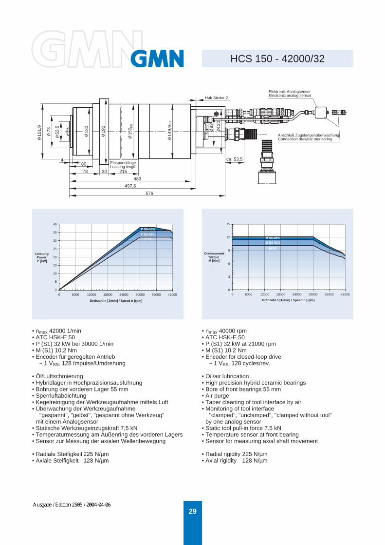
HCS 150 - 42000/32
4
120
83
150 h
5
53,5
80
78
483
497,5
576
ca. 53,5
149,
9-0,
1
73 130
151,
9
190
30
• nmax 42000 1/min• ATC HSK-E 50• P (S1) 32 kW bei 30000 1/min• M (S1) 10,2 Nm• Encoder für geregelten Antrieb
~ 1 VSS, 128 Impulse/Umdrehung
• Öl/Luftschmierung• Hybridlager in Hochpräzisionsausführung• Bohrung der vorderen Lager 55 mm• Sperrluftabdichtung• Kegelreinigung der Werkzeugaufnahme mittels Luft• Überwachung der Werkzeugaufnahme
"gespannt", "gelöst", "gespannt ohne Werkzeug"mit einem Analogsensor
• Statische Werkzeugeinzugskraft 7,5 kN• Temperaturmessung am Außenring des vorderen Lagers• Sensor zur Messung der axialen Wellenbewegung
• Radiale Steifigkeit 225 N/µm• Axiale Steifigkeit 128 N/µm
• nmax 40000 rpm• ATC HSK-E 50• P (S1) 32 kW at 21000 rpm• M (S1) 10.2 Nm• Encoder for closed-loop drive
~ 1 VSS, 128 cycles/rev.
• Oil/air lubrication• High precision hybrid ceramic bearings• Bore of front bearings 55 mm• Air purge• Taper cleaning of tool interface by air• Monitoring of tool interface
"clamped", "unclamped", "clamped without tool"by one analog sensor
• Static tool pull-in force 7.5 kN• Temperature sensor at front bearing• Sensor for measuring axial shaft movement
• Radial rigidity 225 N/µm• Axial rigidity 128 N/µm
EinspannlängeLocating length
215
Hub Stroke 2Elektronik AnalogsensorElectronic analog sensor
Anschluß ZugstangenüberwachungConnection drawbar monitoring
Drehzahl n [1/min] / Speed n [rpm]
LeistungPowerP [kW]
Drehzahl n [1/min] / Speed n [rpm]
DrehmomentTorqueM [Nm]
P S1P S6-60%
M S1
M S6-60%
0 6000 12000 18000 24000 30000 36000 420000
5
10
15
20
25
30
35
40
0 6000 12000 18000 24000 30000 36000 42000
0
3
6
9
12
15
M S6-40%
P S6-40%
WEHRFRIT
Ausgabe / Edition 2505 / 2004-04-06

30
HCS 150g - 18000/9
2
61,5
78,5
103,5
746
2000+50
190
149,
9
130
150 h
5
• nmax 18000 1/min• ATC HSK-A 50• P (S1) 9 kW bei 7500 1/min• M (S1) 11 Nm• Encoder für geregelten Antrieb
~ 1 VSS, 256 Impulse/Umdrehung
• Fett-Dauerschmierung• Hybridlager in Hochpräzisionsausführung• Bohrung der vorderen Lager 55 mm• Sperrluftabdichtung• Kegelreinigung der Werkzeugaufnahme mittels Luft• Überwachung der Werkzeugaufnahme
"gespannt", "gelöst", "gespannt ohne Werkzeug"• Kühlmittel durch die Welle, max. 40 bar
• Radiale Steifigkeit 215 N/µm• Axiale Steifigkeit 130 N/µm
• nmax 18000 rpm• ATC HSK-A 50• P (S1) 9 kW at 7500 rpm• M (S1) 11 Nm• Encoder for closed-loop drive
~ 1 VSS, 256 cycles/rev.
• Permanent grease lubrication• High precision hybrid ceramic bearings• Bore of front bearings 55 mm• Air purge• Taper cleaning of tool interface by air• Monitoring of tool interface
"clamped", "unclamped", "clamped without tool"• Coolant through shaft, max. 40 bar
• Radial rigidity 215 N/µm• Axial rigidity 130 N/µm
Drehzahl n [1/min] / Speed n [rpm]
LeistungPowerP [kW]
Drehzahl n [1/min] / Speed n [rpm]
DrehmomentTorqueM [Nm]
EinspannlängeLocating length 255
ZugstangenüberwachungDrawbar monitoring
MotorMotor
DrehwinkelgeberEncoder
ÜberwachungMonitoring
0
2
4
6
8
10
12
0 3000 6000 9000 12000 15000 18000
P S1
P S6-60%
P S6-40%
0
2
4
6
8
10
12
14
16
0 3000 6000 9000 12000 15000 18000
M S1
M S6-60%
M S6-40%
WEHRFRIT
Ausgabe / Edition 2505 / 2004-04-06
31
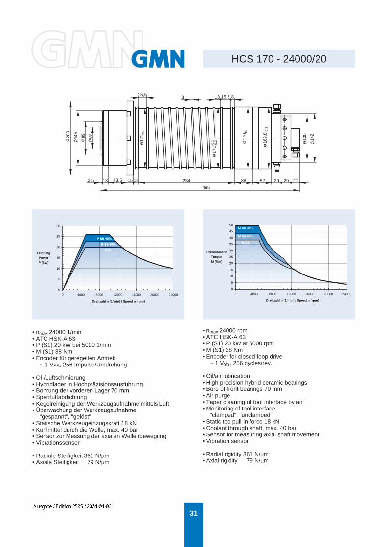
HCS 170 - 24000/20
15,5 133 15,5 8
3,5 13 43,5 15 16 234 38 52 29 29 22
169,
8 -0,
2
170 f
6
171 -
0,2
-0,117
1 h5
200
145
89 68 130
142
495
• nmax 24000 1/min• ATC HSK-A 63• P (S1) 20 kW bei 5000 1/min• M (S1) 38 Nm• Encoder für geregelten Antrieb
~ 1 VSS, 256 Impulse/Umdrehung
• Öl-/Luftschmierung• Hybridlager in Hochpräzisionsausführung• Bohrung der vorderen Lager 70 mm• Sperrluftabdichtung• Kegelreinigung der Werkzeugaufnahme mittels Luft• Überwachung der Werkzeugaufnahme
"gespannt", "gelöst"• Statische Werkzeugeinzugskraft 18 kN• Kühlmittel durch die Welle, max. 40 bar• Sensor zur Messung der axialen Wellenbewegung• Vibrationssensor
• Radiale Steifigkeit 361 N/µm• Axiale Steifigkeit 79 N/µm
• nmax 24000 rpm• ATC HSK-A 63• P (S1) 20 kW at 5000 rpm• M (S1) 38 Nm• Encoder for closed-loop drive
~ 1 VSS, 256 cycles/rev.
• Oil/air lubrication• High precision hybrid ceramic bearings• Bore of front bearings 70 mm• Air purge• Taper cleaning of tool interface by air• Monitoring of tool interface
"clamped", "unclamped"• Static too pull-in force 18 kN• Coolant through shaft, max. 40 bar• Sensor for measuring axial shaft movement• Vibration sensor
• Radial rigidity 361 N/µm• Axial rigidity 79 N/µm
Drehzahl n [1/min] / Speed n [rpm]
DrehmomentTorqueM [Nm]
Drehzahl n [1/min] / Speed n [rpm]
LeistungPowerP [kW]
0
5
10
15
20
25
30
35
40
45
50
0 4000 8000 12000 16000 20000 240000
5
10
15
20
25
30
0 4000 8000 12000 16000 20000 24000
P S1
P S6-60%
P S6-40%M S1
M S6-60%
M S6-40%
WEHRFRIT
Ausgabe / Edition 2505 / 2004-04-06

32
HCS 170 - 24000/27
1,5 68,5
88,5 25 95
621,5
210
169,
9
150
170 h
5
• nmax 24000 1/min• ATC HSK-A 63• P (S1) 27 kW bei 18000 1/min• M (S1) 14 Nm• Encoder für geregelten Antrieb
~ 1 VSS, 256 Impulse/Umdrehung
• Öl-/Luftschmierung• Hybridlager in Hochpräzisionsausführung• Bohrung der vorderen Lager 70 mm• Sperrluftabdichtung• Kegelreinigung der Werkzeugaufnahme mittels Luft• Überwachung der Werkzeugaufnahme
"gespannt", "gelöst", "gespannt ohne Werkzeug"• Kühlmittel durch die Welle, max. 60 bar
• Radiale Steifigkeit 327 N/µm• Axiale Steifigkeit 160 N/µm
• nmax 24000 rpm• ATC HSK-A 63• P (S1) 27 kW at 18000 rpm• M (S1) 14 Nm• Encoder for closed-loop drive
~ 1 VSS, 256 cycles/rev.
• Oil/air lubrication• High precision hybrid ceramic bearings• Bore of front bearings 70 mm• Air purge• Taper cleaning of tool interface by air• Monitoring of tool interface
"clamped", "unclamped", "clamped without tool"• Coolant through shaft, max. 60 bar
• Radial rigidity 327 N/µm• Axial rigidity 160 N/µm
LeistungPowerP [kW]
Drehzahl n [1/min] / Speed n [rpm] Drehzahl n [1/min] / Speed n [rpm]
DrehmomentTorqueM [Nm]
Einspannlänge Locating length 276,9
ZugstangenüberwachungDrawbar monitoring
0
7
14
21
28
35
0 4000 8000 12000 16000 20000 24000
P S1
P S6-60%
P S6-40%
0
4
8
12
16
20
0 4000 8000 12000 16000 20000 24000
M S1
M S6-60%
M S6-40%
WEHRFRIT
Ausgabe / Edition 2505 / 2004-04-06

33
HCS 170 - 24000/41
169,
8 -0
,2
170 h
5
170 h
7
68,599
128,
5 +
0,1
-
169,
8 -0
,2
182
-0,2
167,5
10 2,5
27,5 10 40 10 339 15 73
ca. 777
• nmax 24000 1/min• ATC HSK-A 63• Synchronmotor• P (S1) 41 kW bei 7000 1/min• M (S1) 56 Nm• Encoder für geregelten Antrieb
~ 1 VSS, 256 Impulse/Umdrehung
• Öl-/Luftschmierung• Hybridlager in Hochpräzisionsausführung• Bohrung der vorderen Lager 70 mm• Sperrluftabdichtung• Kegelreinigung der Werkzeugaufnahme mittels Luft• Überwachung der Werkzeugaufnahme
"gespannt", "gelöst", "gespannt ohne Werkzeug"• Statische Werkzeugeinzugskraft 18 kN• Kühlmittel durch die Welle, max. 50 bar
• Radiale Steifigkeit 394 N/µm• Axiale Steifigkeit 297 N/µm
• nmax 24000 rpm• ATC HSK-A 63• Synchronous motor• P (S1) 41 kW at 7000 rpm• M (S1) 56 Nm• Encoder for closed-loop drive
~ 1 VSS, 256 cycles/rev.
• Oil/air lubrication• High precision hybrid ceramic bearings• Bore of front bearings 70 mm• Air purge• Taper cleaning of tool interface by air• Monitoring of tool interface
"clamped", "unclamped", "clamped without tool"• Static tool pull-in force 18 kN• Coolant through shaft, max. 50 bar
• Radial rigidity 394 N/µm• Axial rigidity 297 N/µm
PowerP [kW]
Drehzahl n [1/min] / Speed n [rpm]
Leistung
Drehzahl n [1/min] / Speed n [rpm]
DrehmomentTorqueM [Nm]
Einspannlänge Locating length 250
0
10
20
30
40
50
60
0 4000 8000 12000 16000 20000 24000
0
10
20
30
40
50
60
70
80
0 4000 8000 12000 16000 20000 24000
P S1
P S6-60%
P S6-40%
M S1M S6-60%
M S6-40%
WEHRFRIT
Ausgabe / Edition 2505 / 2004-04-06

34
HCS 170 - 40000/39
1598
395,7 678,1
24,5 15,5
200
246,7
130
7353
,5
172 h
5
172
• nmax 40000 1/min• ATC HSK-E 50• P (S1) 39 kW bei 15000 1/min• M (S1) 24,8 Nm• Encoder für geregelten Antrieb
~ 1 VSS, 256 Impulse/Umdrehung
• Öl-/Luftschmierung• Hybridlager in Hochpräzisionsausführung• Bohrung der vorderen Lager 55 mm• Sperrluftabdichtung• Kegelreinigung der Werkzeugaufnahme mittels Luft• Überwachung der Werkzeugaufnahme
"gespannt", "gelöst"• Statische Werkzeugeinzugskraft 10 kN• Kühlmittel durch die Welle, max. 80 bar• Temperaturmessung am Außenring des vorderen Lagers
zum Ausgleich der axialen Wellenbewegung• Sensor zur Messung der axialen Wellenbewegung
• Radiale Steifigkeit 307 N/µm• Axiale Steifigkeit 102 N/µm
• nmax 40000 rpm• ATC HSK-E 50• P (S1) 39 kW at 15000 rpm• M (S1) 24.8 Nm• Encoder for closed-loop drive
~ 1 VSS, 256 cycles/rev.
• Oil/air lubrication• High precision hybrid ceramic bearings• Bore of front bearings 55 mm• Air purge• Taper cleaning of tool interface by air• Monitoring of tool interface
"clamped", "unclamped"• Static tool pull-in force 10 kN• Coolant through shaft, max. 80 bar• Temperature sensor at front bearing for compensating
axial shaft movement• Sensor for measuring axial shaft movement
• Radial rigidity 307 N/µm• Axial rigidity 102 N/µm
PowerP [kW]
Drehzahl n [1/min] / Speed n [rpm]
Leistung
Drehzahl n [1/min] / Speed n [rpm]
DrehmomentTorqueM [Nm]
0 10000 20000 30000 400000
5
10
15
20
25
30
35
40
45
50
P S1
P S6-60%
P S6-40%
0
5
10
15
20
25
30
35
0 10000 20000 30000 40000
M S1
M S6-60%
M S6-40%
WEHRFRIT
Ausgabe / Edition 2505 / 2004-04-06

35
HCS 170g - 15000/41
2,5 10±0,1
10 27,510 27 13
339 15 73 145
947
167,5
68,5
89
128,
5±0,
1
169,
8 -0,
2
170 h
7
169,
9 -0,
1
170 h
5
182 -
0,2
169,
8 -0,
2
169,
8• nmax 15000 1/min• ATC HSK-A 63• P (S1) 41 kW bei 7000 1/min• M (S1) 56 Nm• Encoder für geregelten Antrieb
~ 1 VSS, 256 Impulse/Umdrehung
• Fett-Dauerschmierung• Hybridlager in Hochpräzisionsausführung• Bohrung der vorderen Lager 70 mm• Sperrluftabdichtung• Kegelreinigung der Werkzeugaufnahme mittels Luft• Überwachung der Werkzeugaufnahme
"gespannt", "gelöst", "gespannt ohne Werkzeug"• Statische Werkzeugeinzugskraft 18 kN• Kühlmittel durch die Welle, max. 50 bar
• Radiale Steifigkeit 394 N/µm• Axiale Steifigkeit 297 N/µm
• nmax 15000 rpm• ATC HSK-A 63• P (S1) 41 kW at 7000 rpm• M (S1) 56 Nm• Encoder for closed-loop drive
~ 1 VSS, 256 cycles/rev.
• Permanent grease lubrication• High precision hybrid ceramic bearings• Bore of front bearings 70 mm• Air purge• Taper cleaning of tool interface by air• Monitoring of tool interface
"clamped", "unclamped", "clamped without tool"• Static tool pull-in force 18 kN• Coolant through shaft, max. 50 bar
• Radial rigidity 394 N/µm• Axial rigidity 297 N/µm
PowerP [kW]
Drehzahl n [1/min] / Speed n [rpm]
Leistung
Drehzahl n [1/min] / Speed n [rpm]
DrehmomentTorqueM [Nm]
Einspannlänge Locating length 250
schwenkbare Versorgungsebeneslewable supply level
0
10
20
30
40
50
60
0 3000 6000 9000 12000 15000
0
10
20
30
40
50
60
70
80
0 3000 6000 9000 12000 15000
P S1
P S6-60%
P S6-40%
M S1
M S6-60%
M S6-40%
WEHRFRIT
Ausgabe / Edition 2505 / 2004-04-06

36
HCS 200 - 18000/15
4 116
15
135
39 30
68
422 231 36
2°
234
98 80 146
202 h
5
200 h
5
130
196
• nmax 18000 1/min• ATC HSK-A 63• P (S1) 15 kW bei 1800 1/min• M (S1) 80 Nm• Encoder für geregelten Antrieb
~ 1 VSS, 256 Impulse/Umdrehung
• Öl-/Luftschmierung• Hybridlager in Hochpräzisionsausführung• Bohrung der vorderen Lager 80 mm• Sperrluftabdichtung• Kegelreinigung der Werkzeugaufnahme mittels Luft• Überwachung der Werkzeugaufnahme
"gespannt", "gelöst", "gespannt ohne Werkzeug"• Statische Werkzeugeinzugskraft 18 kN• Temperaturmessung am Außenring des vorderen Lagers
zum Ausgleich der axialen Wellenbewegung
• Radiale Steifigkeit 535 N/µm• Axiale Steifigkeit 450 N/µm
• nmax 18000 rpm• ATC HSK-A 63• P (S1) 15 kW at 1800 rpm• M (S1) 80 Nm• Encoder for closed-loop drive
~ 1 VSS, 256 cycles/rev.
• Oil/air lubrication• High precision hybrid ceramic bearings• Bore of front bearings 80 mm• Air purge• Taper cleaning of tool interface by air• Monitoring of tool interface
"clamped", "unclamped", "clamped without tool"• Static tool pull-in force 18 kN• Temperature sensor at front bearing for compensating
axial shaft movement
• Radial rigidity 535 N/µm• Axial rigidity 450 N/µm
Drehzahl n [1/min] / Speed n [rpm]
LeistungPowerP [kW]
Drehzahl n [1/min] / Speed n [rpm]
DrehmomentTorqueM [Nm]
EinspannlängeLocating length
EinspannlängeLocating length
ZugstangenüberwachungDrawbar monitoring
0
5
10
15
20
0 3000 6000 9000 12000 15000 18000
P S1
P S6-60%
P S6-40%
0
20
40
60
80
100
120
0 3000 6000 9000 12000 15000 18000
M S1
M S6-60%
M S6-40%
WEHRFRIT
Ausgabe / Edition 2505 / 2004-04-06

37
HCS 200 - 30000/15
4,5
53,5 15
135 295
95
121
30
230
130
73 53,5
189,
9
202 h
5
190
189,
8
189,
6
48 83 128
130
• nmax 30000 1/min• ATC HSK-A 50 oder E 50• P (S1) 15 kW bei 12000 1/min• M (S1) 12 Nm• Encoder für geregelten Antrieb
~ 1 VSS, 256 Impulse/Umdrehung
• Öl-/Luftschmierung• Hybridlager in Hochpräzisionsausführung• Bohrung der vorderen Lager 55 mm• Sperrluftabdichtung• Kegelreinigung der Werkzeugaufnahme mittels Luft• Überwachung der Werkzeugaufnahme
"gespannt", "gelöst", "gespannt ohne Werkzeug"• Statische Werkzeugeinzugskraft 11 kN• Kühlmittel durch die Welle, max. 30 bar
• Radiale Steifigkeit 320 N/µm• Axiale Steifigkeit 110 N/µm
• nmax 30000 rpm• ATC HSK-A 50 or E 50• P (S1) 15 kW at 12000 rpm• M (S1) 12 Nm• Encoder for closed-loop drive
~ 1 VSS, 256 cycles/rev.
• Oil/air lubrication• High precision hybrid ceramic bearings• Bore of front bearings 55 mm• Air purge• Taper cleaning of tool interface by air• Monitoring of tool interface
"clamped", "unclamped", "clamped without tool"• Static tool pull-in force 11 kN• Coolant through shaft, max. 30 bar
• Radial rigidity 320 N/µm• Axial rigidity 110 N/µm
Drehzahl n [1/min] / Speed n [rpm]
LeistungPowerP [kW]
Drehzahl n [1/min] / Speed n [rpm]
DrehmomentTorqueM [Nm]
ZugstangenüberwachungDrawbar monitoring
EinspannlängeLocating length
0
5
10
15
20
0 5000 10000 15000 20000 25000 30000
P S1
P S6-60%
P S6-40%
0
4
8
12
16
0 5000 10000 15000 20000 25000 30000
M S1
M S6-60%
M S6-40%
WEHRFRIT
Ausgabe / Edition 2505 / 2004-04-06

38
HCS 200 - 30000/46
4,5 95 18 27 50 141,1 159,7 205,2 50,6ca. 751,1
68,5
89205
145
250
200 h
5
200 h
5
199
199
• nmax 30000 1/min• ATC HSK-E 63• P (S1) 46 kW bei 15000 1/min• M (S1) 29,3 Nm• Encoder für geregelten Antrieb
~ 1 VSS, 256 Impulse/Umdrehung
• Öl-/Luftschmierung• Hybridlager in Hochpräzisionsausführung• Bohrung der vorderen Lager 70 mm• Sperrluftabdichtung• Kegelreinigung der Werkzeugaufnahme mittels Luft• Überwachung der Werkzeugaufnahme
"gespannt", "gelöst", "gespannt ohne Werkzeug"• Statische Werkzeugeinzugskraft 18 kN• Kühlmittel durch die Welle, max. 80 bar• Sensor zur Messung der axialen Wellenbewegung
• Radiale Steifigkeit 422 N/µm• Axiale Steifigkeit 128 N/µm
• nmax 30000 rpm• ATC HSK-E 63• P (S1) 46 kW at 15000 rpm• M (S1) 29.3 Nm• Encoder for closed-loop drive
~ 1 VSS, 256 cycles/rev.
• Oil/air lubrication• High precision hybrid ceramic bearings• Bore of front bearings 70 mm• Air purge• Taper cleaning of tool interface by air• Monitoring of tool interface
"clamped", "unclamped", "clamped without tool"• Static tool pull-in force 18 kN• Coolant through shaft, max. 80 bar• Sensor for measuring axial shaft movement
• Radial rigidity 422 N/µm• Axial rigidity 128 N/µm
PowerP [kW]
Drehzahl n [1/min] / Speed n [rpm]
Leistung
Drehzahl n [1/min] / Speed n [rpm]
DrehmomentTorqueM [Nm]
M S1
M S6-60%
M S6-40%
0
10
20
30
40
50
60
0 5000 10000 15000 20000 25000 30000
0
5
10
15
20
25
30
35
40
0 5000 10000 15000 20000 25000 30000
P S1
P S6-60%
P S6-40%
WEHRFRIT
Ausgabe / Edition 2505 / 2004-04-06

39
HCS 200g - 12000/15
4 116
15
135
30
68
422 231 36
2°
25,5
23,5
103
234
146
202 h
5
130
200 h
5
196
• nmax 12000 1/min• ATC ISO Kegel SK 40 ohne Nutensteine• P (S1) 15 kW bei 1800 1/min• M (S1) 80 Nm• Encoder für geregelten Antrieb
~ 1 VSS, 256 Impulse/Umdrehung
• Fett-Dauerschmierung• Hybridlager in Hochpräzisionsausführung• Bohrung der vorderen Lager 80 mm• Sperrluftabdichtung• Kegelreinigung der Werkzeugaufnahme mittels Luft• Überwachung der Werkzeugaufnahme
"gespannt", "gelöst", "gespannt ohne Werkzeug"• Statische Werkzeugeinzugskraft 10,5 kN• Temperaturmessung am Außenring des vorderen Lagers
zum Ausgleich der axialen Wellenbewegung
• Radiale Steifigkeit 543 N/µm• Axiale Steifigkeit 460 N/µm
• nmax 12000 rpm• ATC ISO taper SK 40 without drive dogs• P (S1) 15 kW at 1800 rpm• M (S1) 80 Nm• Encoder for closed-loop drive
~ 1 VSS, 256 cycles/rev.
• Permanent grease lubrication• High precision hybrid ceramic bearings• Bore of front bearings 80 mm• Air purge• Taper cleaning of tool interface by air• Monitoring of tool interface
"clamped", "unclamped", "clamped without tool"• Static tool pull-in force 10.5 kN• Temperature sensor at front bearing for compensating
axial shaft movement
• Radial rigidity 543 N/µm• Axial rigidity 460 N/µm
Drehzahl n [1/min] / Speed n [rpm]
LeistungPowerP [kW]
Drehzahl n [1/min] / Speed n [rpm]
DrehmomentTorqueM [Nm]
EinspannlängeLocating length
EinspannlängeLocating length
ZugstangenüberwachungDrawbar monitoring
16
0
5
10
15
20
0 3000 6000 9000 12000
P S1
P S6-60%
P S6-40%
0
20
40
60
80
100
120
0 3000 6000 9000 12000
M S1
M S6-60%
M S6-40%
WEHRFRIT
Ausgabe / Edition 2505 / 2004-04-06
40
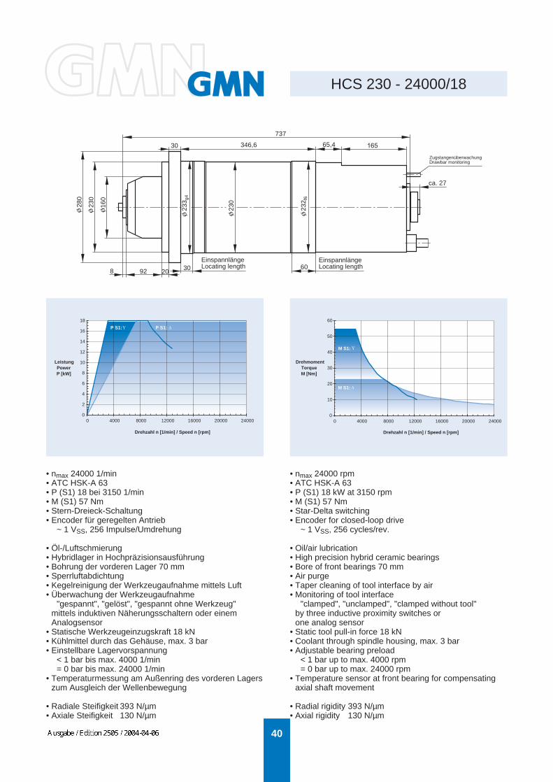
HCS 230 - 24000/18
8 92 20 30 60
ca. 27
16565,4346,630
737
280
230
160
233 g
4
230
232 f
6
• nmax 24000 1/min• ATC HSK-A 63• P (S1) 18 bei 3150 1/min• M (S1) 57 Nm• Stern-Dreieck-Schaltung• Encoder für geregelten Antrieb
~ 1 VSS, 256 Impulse/Umdrehung
• Öl-/Luftschmierung• Hybridlager in Hochpräzisionsausführung• Bohrung der vorderen Lager 70 mm• Sperrluftabdichtung• Kegelreinigung der Werkzeugaufnahme mittels Luft• Überwachung der Werkzeugaufnahme
"gespannt", "gelöst", "gespannt ohne Werkzeug"mittels induktiven Näherungsschaltern oder einemAnalogsensor
• Statische Werkzeugeinzugskraft 18 kN• Kühlmittel durch das Gehäuse, max. 3 bar• Einstellbare Lagervorspannung
< 1 bar bis max. 4000 1/min= 0 bar bis max. 24000 1/min
• Temperaturmessung am Außenring des vorderen Lagerszum Ausgleich der Wellenbewegung
• Radiale Steifigkeit 393 N/µm• Axiale Steifigkeit 130 N/µm
• nmax 24000 rpm• ATC HSK-A 63• P (S1) 18 kW at 3150 rpm• M (S1) 57 Nm• Star-Delta switching• Encoder for closed-loop drive
~ 1 VSS, 256 cycles/rev.
• Oil/air lubrication• High precision hybrid ceramic bearings• Bore of front bearings 70 mm• Air purge• Taper cleaning of tool interface by air• Monitoring of tool interface
"clamped", "unclamped", "clamped without tool"by three inductive proximity switches orone analog sensor
• Static tool pull-in force 18 kN• Coolant through spindle housing, max. 3 bar• Adjustable bearing preload
< 1 bar up to max. 4000 rpm= 0 bar up to max. 24000 rpm
• Temperature sensor at front bearing for compensatingaxial shaft movement
• Radial rigidity 393 N/µm• Axial rigidity 130 N/µm
Drehzahl n [1/min] / Speed n [rpm]
DrehmomentTorqueM [Nm]
Drehzahl n [1/min] / Speed n [rpm]
LeistungPowerP [kW]
EinspannlängeLocating length
EinspannlängeLocating length
ZugstangenüberwachungDrawbar monitoring
0
10
20
30
40
50
60
0 4000 8000 12000 16000 20000 24000
M S1:
M S1:
0
2
4
6
8
10
12
14
16
18
0 4000 8000 12000 16000 20000 24000
P S1: P S1:
WEHRFRIT
Ausgabe / Edition 2505 / 2004-04-06
41
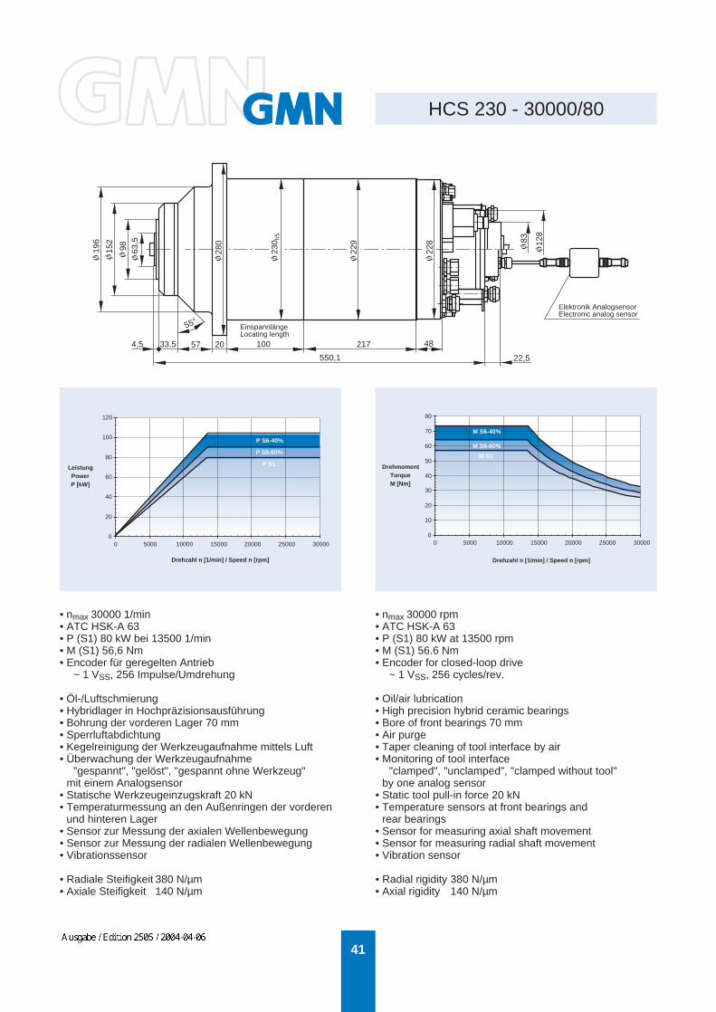
HCS 230 - 30000/80
280
228 12
8
83
4,5 33,5 57 20 48
550,1
230 h
5
229
196
152
98 63,5
55°
217
22,5
• nmax 30000 1/min• ATC HSK-A 63• P (S1) 80 kW bei 13500 1/min• M (S1) 56,6 Nm• Encoder für geregelten Antrieb
~ 1 VSS, 256 Impulse/Umdrehung
• Öl-/Luftschmierung• Hybridlager in Hochpräzisionsausführung• Bohrung der vorderen Lager 70 mm• Sperrluftabdichtung• Kegelreinigung der Werkzeugaufnahme mittels Luft• Überwachung der Werkzeugaufnahme
"gespannt", "gelöst", "gespannt ohne Werkzeug"mit einem Analogsensor
• Statische Werkzeugeinzugskraft 20 kN• Temperaturmessung an den Außenringen der vorderen
und hinteren Lager• Sensor zur Messung der axialen Wellenbewegung• Sensor zur Messung der radialen Wellenbewegung• Vibrationssensor
• Radiale Steifigkeit 380 N/µm• Axiale Steifigkeit 140 N/µm
• nmax 30000 rpm• ATC HSK-A 63• P (S1) 80 kW at 13500 rpm• M (S1) 56.6 Nm• Encoder for closed-loop drive
~ 1 VSS, 256 cycles/rev.
• Oil/air lubrication• High precision hybrid ceramic bearings• Bore of front bearings 70 mm• Air purge• Taper cleaning of tool interface by air• Monitoring of tool interface
"clamped", "unclamped", "clamped without tool"by one analog sensor
• Static tool pull-in force 20 kN• Temperature sensors at front bearings and
rear bearings• Sensor for measuring axial shaft movement• Sensor for measuring radial shaft movement• Vibration sensor
• Radial rigidity 380 N/µm• Axial rigidity 140 N/µm
PowerP [kW]
Drehzahl n [1/min] / Speed n [rpm]
Leistung
Drehzahl n [1/min] / Speed n [rpm]
DrehmomentTorqueM [Nm]
100
EinspannlängeLocating length
Elektronik AnalogsensorElectronic analog sensor
0
20
40
60
80
100
120
0 5000 10000 15000 20000 25000 30000
0
10
20
30
40
50
60
70
80
0 5000 10000 15000 20000 25000 30000
P S1
P S6-60%
P S6-40%
M S1
M S6-60%
M S6-40%
WEHRFRIT
Ausgabe / Edition 2505 / 2004-04-06
42
HCS 230g - 10000/24
46
185
110
170
88,5
228 f
7
229
229,
5
229
230 h
5
229
230 h
5
229
230 h
5
10,5
20 20 100 170 150 42 197,9 383,5 40
30 30 46,6
1286,5
1246,5863
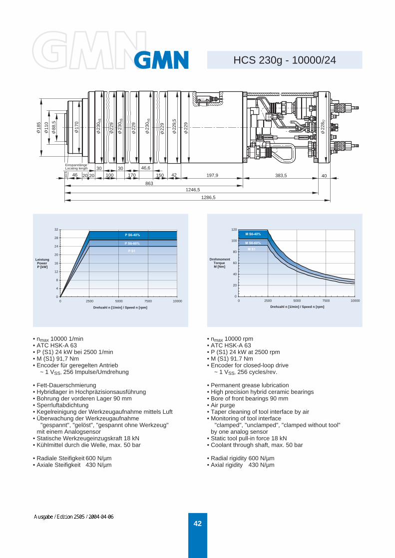
• nmax 10000 1/min• ATC HSK-A 63• P (S1) 24 kW bei 2500 1/min• M (S1) 91,7 Nm• Encoder für geregelten Antrieb
~ 1 VSS, 256 Impulse/Umdrehung
• Fett-Dauerschmierung• Hybridlager in Hochpräzisionsausführung• Bohrung der vorderen Lager 90 mm• Sperrluftabdichtung• Kegelreinigung der Werkzeugaufnahme mittels Luft• Überwachung der Werkzeugaufnahme
"gespannt", "gelöst", "gespannt ohne Werkzeug"mit einem Analogsensor
• Statische Werkzeugeinzugskraft 18 kN• Kühlmittel durch die Welle, max. 50 bar
• Radiale Steifigkeit 600 N/µm• Axiale Steifigkeit 430 N/µm
• nmax 10000 rpm• ATC HSK-A 63• P (S1) 24 kW at 2500 rpm• M (S1) 91.7 Nm• Encoder for closed-loop drive
~ 1 VSS, 256 cycles/rev.
• Permanent grease lubrication• High precision hybrid ceramic bearings• Bore of front bearings 90 mm• Air purge• Taper cleaning of tool interface by air• Monitoring of tool interface
"clamped", "unclamped", "clamped without tool"by one analog sensor
• Static tool pull-in force 18 kN• Coolant through shaft, max. 50 bar
• Radial rigidity 600 N/µm• Axial rigidity 430 N/µm
Drehzahl n [1/min] / Speed n [rpm]
LeistungPowerP [kW]
Drehzahl n [1/min] / Speed n [rpm]
DrehmomentTorqueM [Nm]
EinspannlängeLocating length
P S1
P S6-60%
P S6-40%
M S1
M S6-60%
M S6-40%
0
4
8
12
16
20
24
28
32
0 2500 5000 7500 100000
20
40
60
80
100
120
0 2500 5000 7500 10000
WEHRFRIT
Ausgabe / Edition 2505 / 2004-04-06

43
HCS 230g - 16000/24
46
228 f
7
229
229,
5
230 h
5
229
230 h
5
229
230 h
5
10,5
20 20 100 170 42 197,9 383,5 40
30 30 46,6
1286,5
1246,5713
68,5
145
185 h
6
• nmax 16000 1/min• ATC HSK-A 63• P (S1) 24 kW bei 6000 1/min• M (S1) 38,2 Nm• Encoder für geregelten Antrieb
~ 1 VSS, 256 Impulse/Umdrehung
• Fett-Dauerschmierung• Hybridlager in Hochpräzisionsausführung• Bohrung der vorderen Lager 70 mm• Sperrluftabdichtung• Kegelreinigung der Werkzeugaufnahme mittels Luft• Überwachung der Werkzeugaufnahme
"gespannt", "gelöst", "gespannt ohne Werkzeug"mit einem Analogsensor
• Statische Werkzeugeinzugskraft 18 kN• Kühlmittel durch die Welle, max. 50 bar
• Radiale Steifigkeit 454 N/µm• Axiale Steifigkeit 317 N/µm
• nmax 16000 rpm• ATC HSK-A 63• P (S1) 24 kW at 6000 rpm• M (S1) 38.2 Nm• Encoder for closed-loop drive
~ 1 VSS, 256 cycles/rev.
• Permanent grease lubrication• High precision hybrid ceramic bearings• Bore of front bearings 70 mm• Air purge• Taper cleaning of tool interface by air• Monitoring of tool interface
"clamped", "unclamped", "clamped without tool"by one analog sensor
• Static tool pull-in force 18 kN• Coolant through shaft, max. 50 bar
• Radial rigidity 454 N/µm• Axial rigidity 317 N/µm
Drehzahl n [1/min] / Speed n [rpm]
LeistungPowerP [kW]
Drehzahl n [1/min] / Speed n [rpm]
DrehmomentTorqueM [Nm]
EinspannlängeLocating length
0
4
8
12
16
20
24
28
32
0 2000 4000 6000 8000 10000 12000 14000 160000
5
10
15
20
25
30
35
40
45
50
0 2000 4000 6000 8000 10000 12000 14000 16000
M S1
M S6-60%
M S6-40%
P S1
P S6-60%
P S6-40%
WEHRFRIT
Ausgabe / Edition 2505 / 2004-04-06

44
HCS 232g - 15000/9
ca. 31,5
238
30
ca. 795
440
31,5
62
25 30
270
140
232 g
5
224
232 f
5
220
• nmax 15000 1/min• ATC HSK-A 63• P (S1) 9 kW bei 1220 1/min• M (S1) 70 Nm• Encoder für geregelten Antrieb
~ 1 VSS, 256 Impulse/Umdrehung
• Fett-Dauerschmierung• Hybridlager in Hochpräzisionsausführung• Bohrung der vorderen Lager 80 mm• Sperrluftabdichtung• Kegelreinigung der Werkzeugaufnahme mittels Luft• Überwachung der Werkzeugaufnahme
"gespannt", "gelöst", "gespannt ohne Werkzeug"• Statische Werkzeugeinzugskraft 18 kN• Kühlmittel durch die Welle, max. 80 bar
• Radiale Steifigkeit 242 N/µm• Axiale Steifigkeit 225 N/µm
• nmax 15000 rpm• ATC HSK-A 63• P (S1) 9 kW at 1220 rpm• M (S1) 70 Nm• Encoder for closed-loop drive
~ 1 VSS, 256 cycles/rev.
• Permanent grease lubrication• High precision hybrid ceramic bearings• Bore of front bearings 80 mm• Air purge• Taper cleaning of tool interface by air• Monitoring of tool interface
"clamped", "unclamped", "clamped without tool"• Static tool pull-in force 18 kN• Coolant through shaft, max. 80 bar
• Radial rigidity 242 N/µm• Axial rigidity 225 N/m
Drehzahl n [1/min] / Speed n [rpm]
LeistungPowerP [kW]
Drehzahl n [1/min] / Speed n [rpm]
DrehmomentTorqueM [Nm]
EinspannlängeLocating length
EinspannlängeLocating length
0
3
6
9
12
0 3000 6000 9000 12000 15000
P S1
P S6-60%
P S6-40%
0
20
40
60
80
100
0 3000 6000 9000 12000 15000
M S1
M S6-60%
M S6-40%
WEHRFRIT
Ausgabe / Edition 2505 / 2004-04-06

45
HCS 275 - 20000/60
115
(25)125
50
183
51
212,1 26,9 450
65
170
89 68,5
275 h
5
271
230
272,
95-0
,05
230
254 26
5
• nmax 20000 1/min• ATC HSK-A 63• P (S1) 60 kW bei 10000 1/min• M (S1) 57 Nm• Encoder für geregelten Antrieb
~ 1 VSS, 256 Impulse/Umdrehung
• Öl-/Luftschmierung• Hybridlager in Hochpräzisionsausführung• Bohrung der vorderen Lager 70 mm• Sperrluftabdichtung• Kegelreinigung der Werkzeugaufnahme mittels Luft• Überwachung der Werkzeugaufnahme
"gespannt", "gelöst", "gespannt ohne Werkzeug"• Statische Werkzeugeinzugskraft 18 kN• Kühlmittel durch die Welle, max. 55 bar• Temperaturmessung am Außenring des vorderen Lagers
zum Ausgleich der axialen Wellenbewegung
• Radiale Steifigkeit 442 N/µm• Axiale Steifigkeit 170 N/µm
• nmax 20000 rpm• ATC HSK-A 63• P (S1) 60 kW at 10000 rpm• M (S1) 57 Nm• Encoder for closed-loop drive
~ 1 VSS, 256 cycles/rev.
• Oil/air lubrication• High precision hybrid ceramic bearings• Bore of front bearings 70 mm• Air purge• Taper cleaning of tool interface by air• Monitoring of tool interface
"clamped", "unclamped", "clamped without tool"• Static tool pull-in force 18 kN• Coolant through shaft, max. 55 bar• Temperature sensor at front bearing for compensating
axial shaft movement
• Radial rigidity 442 N/µm• Axial rigidity 170 N/µm
Drehzahl n [1/min] / Speed n [rpm]
LeistungPowerP [kW]
Drehzahl n [1/min] / Speed n [rpm]
DrehmomentTorqueM [Nm]
EinspannlängeLocating length
EinspannlängeLocating length
0
20
40
60
80
0 4000 8000 12000 16000 20000
P S1
P S6-60%
P S6-40%
0
20
40
60
80
0 4000 8000 12000 16000 20000
M S1
M S6-60%
M S6-40%
WEHRFRIT
Ausgabe / Edition 2505 / 2004-04-06

46
HCS 285 - 12000/32
182,5 76 34 85 195 100 170 41 30 411 28 ca. 90
1380
290
145
108,
5
225
264
285 h
5
283,
5 -0,
1
284 h
5
283,
9 -0,
2
283,
9 -0,
1
283,
8 -0,
1
280
• nmax 12000 1/min• ATC HSK-A 100• P (S1) 32 kW bei 1000 1/min• M (S1) 306 Nm• Stern-Dreieck-Schaltung• Encoder für geregelten Antrieb
~ 1 VSS, 256 Impulse/Umdrehung
• Öl-/Luftschmierung• Hybridlager in Hochpräzisionsausführung• Bohrung der vorderen Lager 110 mm• Sperrluftabdichtung• Kegelreinigung der Werkzeugaufnahme mittels Luft• Überwachung der Werkzeugaufnahme
"gespannt", "gelöst", "gespannt ohne Werkzeug"• Statische Werkzeugeinzugskraft 45 kN• Kühlmittel durch die Welle, max. 80 bar• Kühlmittel durch das Gehäuse, max. 4 bar
• Radiale Steifigkeit 1030 N/µm• Axiale Steifigkeit 600 N/µm
• nmax 12000 rpm• ATC HSK-A 100• P (S1) 32 kW at 1000 rpm• M (S1) 306 Nm• Star-Delta switching• Encoder for closed-loop drive
~ 1 VSS, 256 cycles/rev.
• Oil/air lubrication• High precision hybrid ceramic bearings• Bore of front bearings 110 mm• Air purge• Taper cleaning of tool interface by air• Monitoring of tool interface
"clamped", "unclamped", "clamped without tool"• Static tool pull-in force 45 kN• Coolant through shaft, max. 80 bar• Coolant through spindle housing, max. 4 bar
• Radial rigidity 1030 N/µm• Axial rigidity 600 N/µm
Drehzahl n [1/min] / Speed n [rpm]
LeistungPowerP [kW]
Drehzahl n [1/min] / Speed n [rpm]
DrehmomentTorqueM [Nm]
ZugstangenüberwachungDrawbar monitoring
0
8
16
24
32
0 3000 6000 9000 12000
P S1:
0
80
160
240
320
0 3000 6000 9000 12000
M S1:
M S1:
P S1:
WEHRFRIT
Ausgabe / Edition 2505 / 2004-04-06
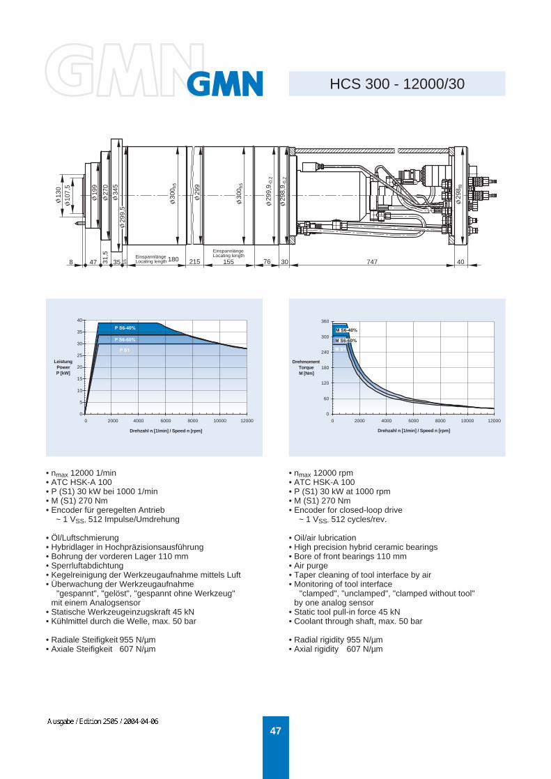
47
HCS 300 - 12000/3031
,5
8
130
107,
5
199
270
345
299,
5
299
300 h
5
300 h
5
299,
9 -0,
2
298,
9 -0,
2
298 f
8
47 35 15 215 76 30 747 40
• nmax 12000 1/min• ATC HSK-A 100• P (S1) 30 kW bei 1000 1/min• M (S1) 270 Nm• Encoder für geregelten Antrieb
~ 1 VSS, 512 Impulse/Umdrehung
• Öl/Luftschmierung• Hybridlager in Hochpräzisionsausführung• Bohrung der vorderen Lager 110 mm• Sperrluftabdichtung• Kegelreinigung der Werkzeugaufnahme mittels Luft• Überwachung der Werkzeugaufnahme
"gespannt", "gelöst", "gespannt ohne Werkzeug"mit einem Analogsensor
• Statische Werkzeugeinzugskraft 45 kN• Kühlmittel durch die Welle, max. 50 bar
• Radiale Steifigkeit 955 N/µm• Axiale Steifigkeit 607 N/µm
• nmax 12000 rpm• ATC HSK-A 100• P (S1) 30 kW at 1000 rpm• M (S1) 270 Nm• Encoder for closed-loop drive
~ 1 VSS, 512 cycles/rev.
• Oil/air lubrication• High precision hybrid ceramic bearings• Bore of front bearings 110 mm• Air purge• Taper cleaning of tool interface by air• Monitoring of tool interface
"clamped", "unclamped", "clamped without tool"by one analog sensor
• Static tool pull-in force 45 kN• Coolant through shaft, max. 50 bar
• Radial rigidity 955 N/µm• Axial rigidity 607 N/µm
EinspannlängeLocating length 180 155
EinspannlängeLocating length
Drehzahl n [1/min] / Speed n [rpm]
DrehmomentTorqueM [Nm]
Drehzahl n [1/min] / Speed n [rpm]
LeistungPowerP [kW]
M S1
P S6-60%
P S6-40%
P S1
0
5
10
15
20
25
30
35
40
0 2000 4000 6000 8000 10000 12000
0
60
120
180
240
300
360
0 2000 4000 6000 8000 10000 12000
M S6-60%
M S6-40%
WEHRFRIT
Ausgabe / Edition 2505 / 2004-04-06
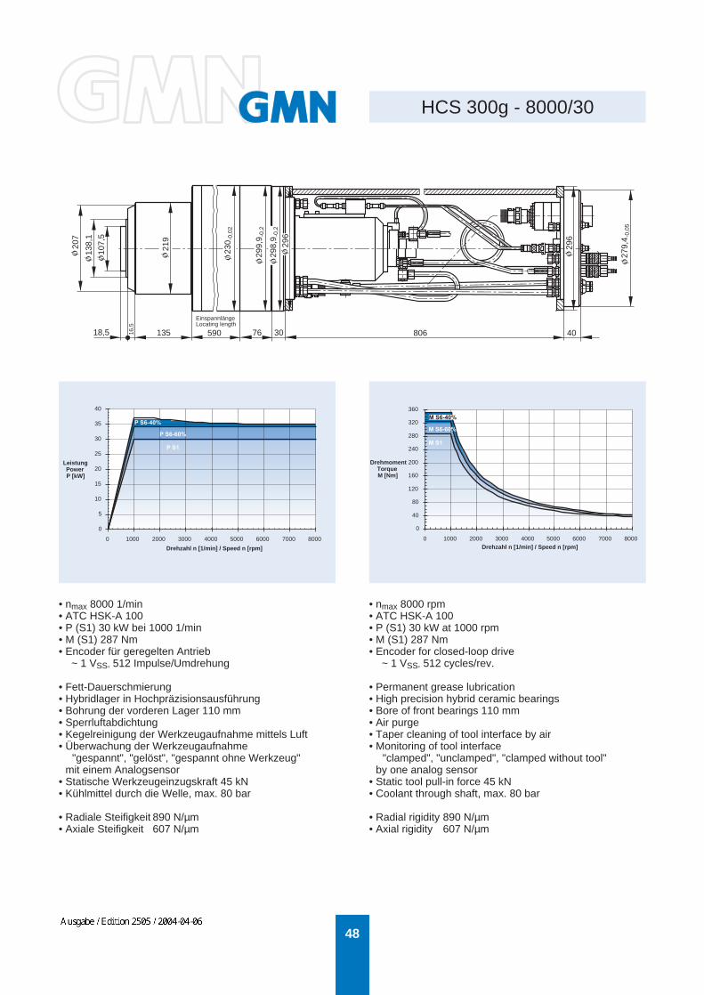
48
HCS 300g - 8000/3010
7,5
135
138,
1
207
230 -
0,02
219
299,
9 -0,
2
298,
9 -0,
2
296
296
279,
4 -0,
05
18,5 16,5
76 30 806 40
• nmax 8000 1/min• ATC HSK-A 100• P (S1) 30 kW bei 1000 1/min• M (S1) 287 Nm• Encoder für geregelten Antrieb
~ 1 VSS, 512 Impulse/Umdrehung
• Fett-Dauerschmierung• Hybridlager in Hochpräzisionsausführung• Bohrung der vorderen Lager 110 mm• Sperrluftabdichtung• Kegelreinigung der Werkzeugaufnahme mittels Luft• Überwachung der Werkzeugaufnahme
"gespannt", "gelöst", "gespannt ohne Werkzeug"mit einem Analogsensor
• Statische Werkzeugeinzugskraft 45 kN• Kühlmittel durch die Welle, max. 80 bar
• Radiale Steifigkeit 890 N/µm• Axiale Steifigkeit 607 N/µm
• nmax 8000 rpm• ATC HSK-A 100• P (S1) 30 kW at 1000 rpm• M (S1) 287 Nm• Encoder for closed-loop drive
~ 1 VSS, 512 cycles/rev.
• Permanent grease lubrication• High precision hybrid ceramic bearings• Bore of front bearings 110 mm• Air purge• Taper cleaning of tool interface by air• Monitoring of tool interface
"clamped", "unclamped", "clamped without tool"by one analog sensor
• Static tool pull-in force 45 kN• Coolant through shaft, max. 80 bar
• Radial rigidity 890 N/µm• Axial rigidity 607 N/µm
Drehzahl n [1/min] / Speed n [rpm]
LeistungPowerP [kW]
Drehzahl n [1/min] / Speed n [rpm]
DrehmomentTorqueM [Nm]
EinspannlängeLocating length
590
M S1
0
5
10
15
20
25
30
35
40
0 1000 2000 3000 4000 5000 6000 7000 8000
0
40
80
120
160
200
240
280
320
360
0 1000 2000 3000 4000 5000 6000 7000 8000
P S6-60%
P S6-40%
P S1
M S6-40%
M S6-60%
WEHRFRIT
Ausgabe / Edition 2505 / 2004-04-06
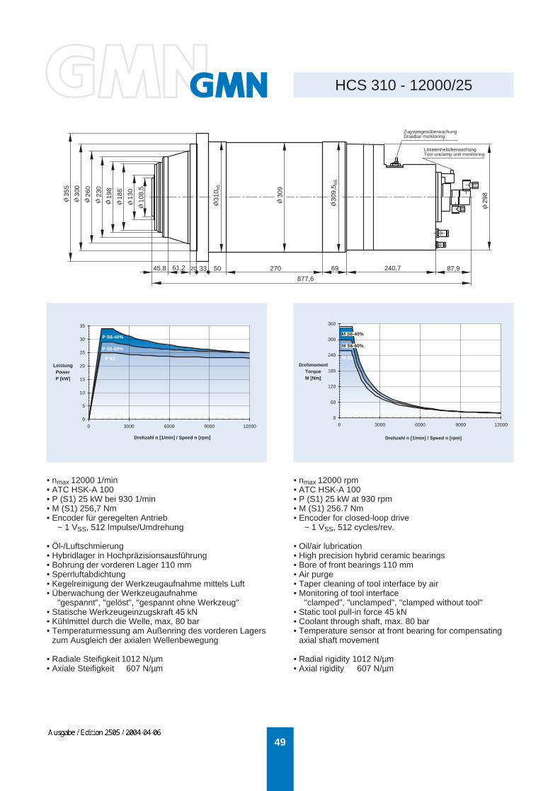
49
HCS 310 - 12000/25
355
300
260
230
198
186
130
108,
5
310 h
5
309
309,
5 h5
298
45,8 61,2 20 33 50 270 69 240,7 87,9
877,6
• nmax 12000 1/min• ATC HSK-A 100• P (S1) 25 kW bei 930 1/min• M (S1) 256,7 Nm• Encoder für geregelten Antrieb
~ 1 VSS, 512 Impulse/Umdrehung
• Öl-/Luftschmierung• Hybridlager in Hochpräzisionsausführung• Bohrung der vorderen Lager 110 mm• Sperrluftabdichtung• Kegelreinigung der Werkzeugaufnahme mittels Luft• Überwachung der Werkzeugaufnahme
"gespannt", "gelöst", "gespannt ohne Werkzeug"• Statische Werkzeugeinzugskraft 45 kN• Kühlmittel durch die Welle, max. 80 bar• Temperaturmessung am Außenring des vorderen Lagers
zum Ausgleich der axialen Wellenbewegung
• Radiale Steifigkeit 1012 N/µm• Axiale Steifigkeit 607 N/µm
• nmax 12000 rpm• ATC HSK-A 100• P (S1) 25 kW at 930 rpm• M (S1) 256.7 Nm• Encoder for closed-loop drive
~ 1 VSS, 512 cycles/rev.
• Oil/air lubrication• High precision hybrid ceramic bearings• Bore of front bearings 110 mm• Air purge• Taper cleaning of tool interface by air• Monitoring of tool interface
"clamped", "unclamped", "clamped without tool"• Static tool pull-in force 45 kN• Coolant through shaft, max. 80 bar• Temperature sensor at front bearing for compensating
axial shaft movement
• Radial rigidity 1012 N/µm• Axial rigidity 607 N/µm
PowerP [kW]
Drehzahl n [1/min] / Speed n [rpm]
Leistung
Drehzahl n [1/min] / Speed n [rpm]
DrehmomentTorqueM [Nm]
ZugstangenüberwachungDrawbar monitoring
LöseeinheitüberwachungTool unclamp unit monitoring
P S1
P S6-60%
P S6-40%
M S1
0
5
10
15
20
25
30
35
0 3000 6000 9000 12000
0
60
120
180
240
300
360
0 3000 6000 9000 12000
M S6-60%
M S6-40%
WEHRFRIT
Ausgabe / Edition 2505 / 2004-04-06