Kaaeid A. Lokhandwala and Ankur Jariwala - … LRGCC2007 Pres.pdfKaaeid A. Lokhandwala and Ankur...
23
1 HIGH PERFORMANCE CONTAMINANT RESISTANT MEMBRANES MINIMIZE PRETREATMENT AND IMPROVE CO 2 REMOVAL ECONOMICS Kaaeid A. Lokhandwala and Ankur Jariwala Membrane Technology and Research, Inc. (MTR) Michael G. Malsam Randall Gas Technologies A Division of ABB Lummus Global (ABB)
Transcript of Kaaeid A. Lokhandwala and Ankur Jariwala - … LRGCC2007 Pres.pdfKaaeid A. Lokhandwala and Ankur...
1
HIGH PERFORMANCE CONTAMINANT RESISTANT MEMBRANES MINIMIZE PRETREATMENT AND IMPROVE CO2 REMOVAL
ECONOMICS
Kaaeid A. Lokhandwala and Ankur JariwalaMembrane Technology and Research, Inc. (MTR)
Michael G. MalsamRandall Gas TechnologiesA Division of ABB Lummus Global (ABB)
2
Outline
• ABB–Randall Gas Technologies/MTR Alliance
• Composite Membranes• Materials selection flexibility
• Improved stability and fouling resistance
• Carbon Dioxide Separation• Increasing the Range of Applications
• Membrane Design aspects for Producer Success in Gas Field
Applications
• Design Issues to Consider in Membrane Process Design
3
ABB–Randall Gas Technologies and MTRAlliance in the Area of Natural Gas Processing
• Randall Gas Technologies• A division of ABB Lummus Global (ABB), An international EPC company
• A gas processing technology and engineering company
• Vast Experience in Gas Processing Plant Design and Engineering
• Membrane Technology and Research, Inc. (MTR) • A supplier of membrane gas separation systems
• A leader in membrane and membrane process development
• Commercialized several types of membranes addressing various
separations such as remote gas conditioning, H2S separation, N2/CH4
separation.
4
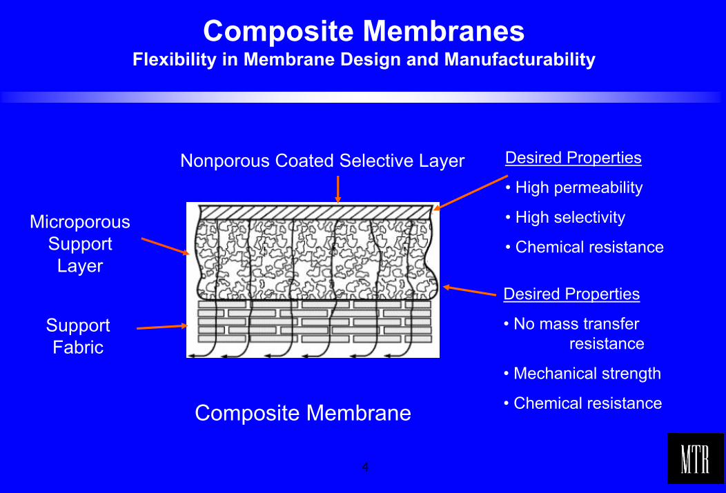
Composite MembranesFlexibility in Membrane Design and Manufacturability
Desired Properties
• High permeability
• High selectivity
• Chemical resistance
Nonporous Coated Selective Layer
MicroporousSupportLayer
Desired Properties
• No mass transfer resistance
• Mechanical strength
• Chemical resistance
SupportFabric
Composite Membrane
5
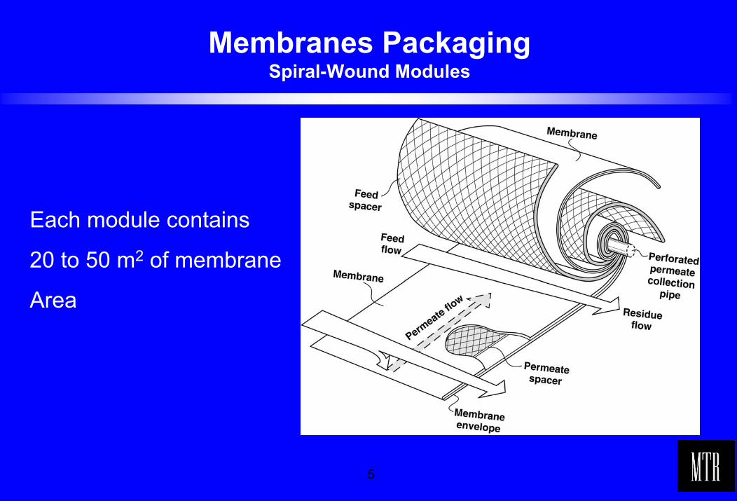
Membranes Packaging Spiral-Wound Modules
Each module contains
20 to 50 m2 of membrane
Area
6
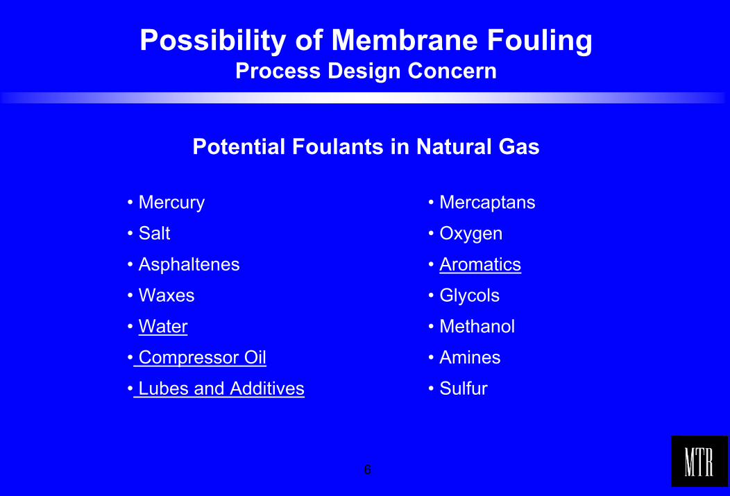
Possibility of Membrane FoulingProcess Design Concern
Potential Foulants in Natural Gas
• Mercury
• Salt
• Asphaltenes
• Waxes
• Water
• Compressor Oil
• Lubes and Additives
• Mercaptans
• Oxygen
• Aromatics
• Glycols
• Methanol
• Amines
• Sulfur
7
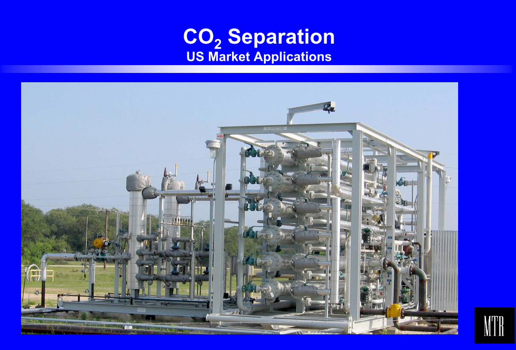
CO2 SeparationUS Market Applications
8
CO2 SeparationUS Market Applications
• MTR/ABB have combined with Dominion Field Services to market treating services for high-CO2 natural gas. Allowing producers to bring additional gas to market.
• The approach has been to develop a complete standardized processand equipment solution including inlet piping, compression, and pretreatment to provide a one-stop solution for independent producers.
• This has been accomplished by focusing on several key process and engineering aspects which are discussed below in more detail.
9
Design AspectsLimited Pretreatment
• Pretreatment consists of using filter/separators and managing temperatures to control hydrocarbon dew point.
• The gas from the recycle compressor requires only a filter/separator to remove lube oil and trace contaminates. However, investment in a small sacrificial carbon guard bed could be economically justified by the extra protection provided.
• The feed is conditioned to remove water, thus avoiding free water formation that would cause corrosion.
• For gases rich in heavy hydrocarbons, the feed is also superheated in a field heater to avoid hydrocarbon condensation
10
Design AspectsWide Range Of Applicability
• These standard CO2 membrane skids are designed for contract CO2treating on the U.S. Gulf Coast by Dominion Field Services
• The membrane treatment solution designed to be operationally more flexible and have a higher net gas recovery compared to amine-based alternatives.
• Typical CO2 treatment ranges from 3-11 mol% CO2, and from 2-10 MMSCFD flow.
• The membrane system is designed for wide turndown. Nominal performance for the larger model standard skid is 7 MMSCFD of feed containing 7 percent CO2, with 2 percent CO2 in the sales product.
• A wide range of NGL content is accommodated. The feed can be very lean coal seam type gas or associated gas with a few gal/1000scf NGL.
11
Design AspectsHigh Btu Recovery
• Minimal gas shrinkage, high Btu recovery was a prime objective in the CO2 process development we are describing. Gas shrinkage comes from compressor fuel requirements and methane lost in the CO2 vent.
• In order to compete with amine units, gas shrinkage must be small. Historically, gas shrinkage of membrane systems was competitive at higher CO2 concentrations, but suffered particularly high methane losses with 3-11 percent CO2 in the feed.
• MTR/ABB’s new patent pending process has three membrane stages for high recovery mated with a single standard three-stage reciprocating compressor typically found in gathering systems.
• For many applications, gas shrinkage is less than 2 percent of the inlet gas.
12
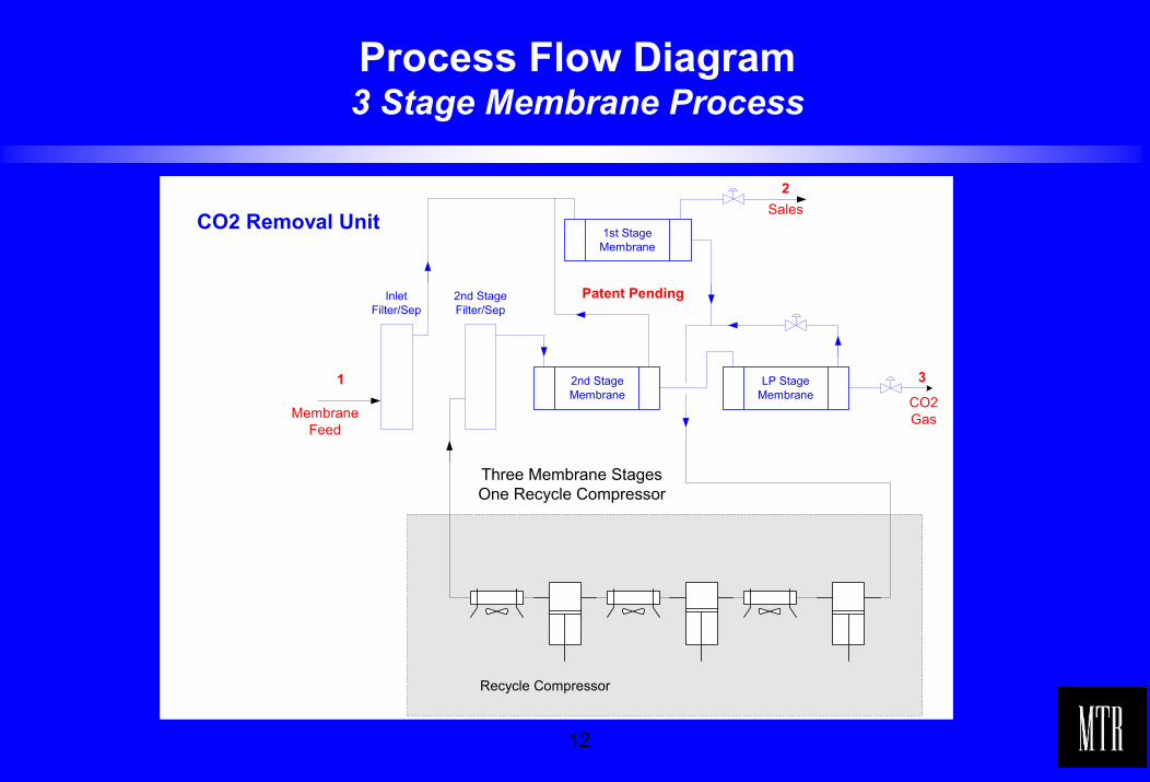
Process Flow Diagram3 Stage Membrane Process
1 3
2
MembraneFeed
Sales
CO2Gas
Recycle Compressor
InletFilter/Sep
2nd StageFilter/Sep
1st StageMembrane
2nd StageMembrane
LP StageMembrane
CO2 Removal Unit
Patent Pending
Three Membrane StagesOne Recycle Compressor
13
Design AspectsScope Of Facility
• The skid was designed with minimal field construction in mind.
• The membrane system and filter separator are supplied as skid mounted systems.
• The system includes a complete PLC-based control system.
• It only takes a few hours to unload and set the skid mounted equipment.
• No equipment requires foundations. Normally, soil is compacted and equipment is placed on pads topped with gravel.
• The relatively light and small equipment is easily transported and unloaded on-site. The membrane skid is similar in size to the direct fired reboiler used on a comparable amine system.
14
Design AspectsMinimized skids – Rapid Deployment
• A typical installation has the membrane skidthe membrane filter/separator skida skid mounted recycle compressora skid for auxiliary equipmenta portable building.
• Dominion is building an inventory of membrane units and other equipment for rapid deployment. This allows the producer to begin production ASAP. It also makes the project schedule for installing this membrane solution very competitive with the reinstallation of an existing amine system.
15
Startup and Performance TestsDominion E&P – Sheridan, Texas
• Dominion's Alverstone unit near Sheridan, Texas, has been in operation since April 2006.
• Alverstone unit was designed for a feed pressure of 975 psig and5.125 mol-% CO2
• Start-up conditions were a feed of 6.4 mol-% CO2 at 710 psig. Initially, the membrane skid was only half loaded because available gas volumes were low.
• The membrane unit lowered the CO2 in the sales gas stream to 1.83 mol-% during the performance test.
• The vent stream averaged 78.4 mol-% CO2; this allowed 98.8 % retention of the membrane inlet Btu value in the sales gas stream.
16
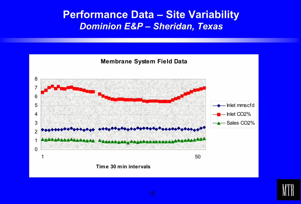
Performance Data – Site VariabilityDominion E&P – Sheridan, Texas
Membrane System Field Data
0
1
2
3
4
5
6
7
8
1 50
Time 30 min intervals
Inlet mmscfd
Inlet CO2%
Sales CO2%
17
Potential Design IssuesTo Consider – 1
• Dew Point Management
Before proceeding with a project, information regarding gas temperature, pressure and detailed gas composition should be known.
Typically, 30 degrees of super heat is applied to the gas beforebeing processed through the membranes.
The membrane itself is tolerant of NGL liquids, but continuous two-phase flow must be avoided. Crossing over into the dew point region has been observed in the field.
The presence of liquids reduces mass transfer. When proper temperature is restored, the membrane dries out in a few minutes and performance fully recovers.
18
Potential Design IssuesTo Consider - 2
• Safe Purging
A system must be safely purged to remove air before start-up.
Reverse pressurization on the membrane modules during purging can cause severe mechanical damage to membrane modules. Attention to details during design and operation of the unit are necessary.
The membrane include a PLC program to assist the operator duringpurging.
The PLC provides instructions and opens and closes automated valves during purging.
19
Potential Design IssuesTo Consider – 3
• Safe Shutdown
A safe and systematic shutdown of the membrane system is performed by the PLC.
The system is isolated and blown down on shutdown.
The membrane system includes special blow-down valves designed to prevent condensation of NGLs that can occur during shutdown.
20
Potential Design IssuesTo Consider – 4
• Automated OperationThe membrane system is controlled from the PLC screen.The PLC screen has a graphical user interface for easy operation. Start-up and normal operation of the unit can be achieved without opening or closing any manual isolation valves on the membrane skid. The PLC system has been successfully interfaced with a SCADA system for remote monitoring.
• Startup TimeRoutine start-up of the membrane system can be achieved in a few minutes.Membranes reach steady state quickly. The PLC helps automate start-up, providing instructions to the operator and automatically ramping set points during start-up. A single operator can start the unit. If auxiliary equipment is ready for service, startups typically take only 15-30 minutes.
21
Potential Design IssuesTo Consider – 5
• PretreatmentAlthough the membranes for this system are engineered to be tolerant of contaminants, gross contaminants should be avoided.A good upstream operation to remove dirt, oil, TEG etc. helps protect the membrane system.The filter coalescer elements before the membrane unit are “last line of defense.” The filter coalescer used in this project removes several quarts a day of lube oil from the recycle gas stream. The filter coalescer on the inlet stream is downstream of a TEG unit.
• Upstream EnvironmentThe membrane system needs to be able to tolerate changes in the upstream environment. Frequent changes in gas volume composition and availability are possible due to normal field operations. The automation of the membrane unit keeps it online through most changes in field conditions.The ability to easily restart is a benefit when gas flow is discontinued due to field compression or well problems.
22
Summary/Conclusions
• To enable natural gas producers to monetize high-CO2 gas in the US Gulf Coast, MTR/ABB and DFS have combined to lease a completely packaged membrane solution for acid gas reduction in natural gas.
• Robust membranes that require a minimal amount of pretreatment, using standardized skids and very high Btu recovery processes, have been developed and demonstrated commercially.
• Newer membranes, more predictable designs that are operator friendly, and easy adapted to field conditions, will allow the range of membrane applications to significantly increase.
23
Thank You!
Membrane Technology and Research, Inc. (MTR)1360 Willow Road, Menlo Park, CA 94025
Telephone: 650-328-2228 Fax: 650-328-6580Website: www.mtrinc.com
and
Randall Gas TechnologiesA Division of Lummus Process Technology
ABB Lummus Global3010 Briarpark, Houston, TX 77042
Telephone: 713-821-4100 Fax: 713-821-3538Website: www.abb.com\lummus