K - CK - CCK - Transfluid · A Transfluid fluid coupling reduces the motor’s current peak during...
32
K - CK - CCK FLUID COUPLINGS
Transcript of K - CK - CCK - Transfluid · A Transfluid fluid coupling reduces the motor’s current peak during...
K - CK - CCKFLUID COUPLINGS
Fluid couplings - 1605
INDICE
1
DESCRIPTION
PERFORMANCE CURVES
STARTING TORQUE CHARATERISTICS
ADVANTAGES
STANDARD OR REVERSE MOUNTING
PRODUCTION PROGRAM
SPECIAL VERSION (ATEX)
SELECTION
DIMENSIONS (IN LINE VERSION)
CENTER OF GRAVITY AND MOMENT OF INERTIA
DIMENSIONS (PULLEY VERSIONS)
SAFETY DEVICES
OTHER TRANSFLUID PRODUCTS
SALES NETWORK
pag. 2
3
4
5
6
7 ÷ 8
8
9 ÷ 12
13 ÷ 23
24
25 ÷ 26
27 ÷ 29
30

Fluid couplings - 1605
DESCRIPTION & OPERATING CONDITIONS
2
1. DESCRIPTIONThe TRANSFLUID coupling (K series) is a constant fill type, comprising of three main elements:1 - driving impeller (pump) mounted on the input shaft.2 - driven impeller (turbine) mounted on the output shaft.3 - cover, flanged to the outer impeller, with an oil-tight seal.The first two elements can work both as pump or turbine.
2. OPERATING CONDITIONSThe TRANSFLUID coupling is a hydrodynamic transmission. The impellers perform like a centrifugal pump and a hydraulic turbine. With an input drive to the pump (e.g. electric motor or Diesel engine) kinetic energy is transferred to the oil in the coupling. The oil is forced, by centrifugal force, across the blades of the pump towards the outside of the coupling.The turbine absorbs kinetic energy and generates a torque always equal to input torque, thus causing rotation of the output shaft. Since there are no mechanical connections, the wear is practically zero.The efficiency is influenced only by the speed difference (slip) between pump and turbine.
The slip is essential for the correct operation of the coupling - there could not be torque transmission without slip! The formula for slip, from which the power loss can be deduced is as follows:
In normal conditions (standard duty), slip can vary from 1,5% (large power applications) to 6% (small power applications).TRANSFLUID couplings follow the laws of all centrifugal machines:
1 - transmitted torque is proportional to the square of input speed; 2 - transmitted power is proportional to the third power of input
speed;3 - transmitted power is proportional to the fifth power of circuit
outside diameter.
Slip % = x 100input speed - output speed
input speed
INPUT
1 - INNER IMPELLER2 - OUTER IMPELLER3 - COVER4 - FLEX COUPLING
INPUTOUTPUT
OUTPUT

Fluid couplings - 1605
PERFORMANCE CURVES
3
2.1 Transfluid coupling fitted on electric motorsThree phase asynchronous squirrel cage motors are able to supply maximum torque only, near synchronous speed. Direct starting is the system utilized the most. Figure 1 illustrates the relationship between torque and current. It can be seen that the absorbed current is proportional to the torque only between 85% and 100% of the asynchronous speed.
Any drive system using a Transfluid fluid coupling has the advantage of the motor starting essentially without load. Figure 2 compares the current demands of an electric motor when the load is directly attached verses the demand when a fluid coupling is mounted between the motor and load. The coloured area shows the energy that is lost, as heat, during start-up when a fluid coupling is not used. A Transfluid fluid coupling reduces the motor’s current peak during start-up and also reduces the current losses, increasing the lifetime of electric motors. Also at start-up, a fluid coupling allows more torque to pass to the load for acceleration than in drive systems without a fluid coupling.
Figure 3 shows two curves for a single fluid coupling and a characteristic curve of an electric motor. It is obvious from the stall curve of the fluid coupling (s = 100%) and the available motor torque, how much torque is available to accelerate the rotor of the motor (colored area). In about 1 second, the rotor of the motor accelerates passing from point A to point B. The acceleration of the load, however, is made gradually by the fluid coupling, utilizing the motor in optimal conditions, along the part of the curve between point B, 100% and point C, 2-5%. Point C is the typical point of operation during normal running.
With a motor connected directly to the load there are the following disadvantages:• The difference between available torque and the torque required
by the load is very low until the rotor has accelerated to between 80-85% of the synchronous speed.
• The absorbed current is high (up to 6 times the nominal current) throughout the starting phase causing overheating of the windings, overloads in the electrical lines and, in cases of frequent starts, major production costs.
• Over-dimensioned motors caused by the limitations indicated above.
To limit the absorbed current of the motor during the acceleration of the load, a ( λ Δ) (wye - delta) starting system is frequently used which reduces the absorbed current by about 1/3 during starting. Unfortunately, during operation of the motor under the delta configuration, the available torque is also reduced by 1/3;and for machines with high inertias to accelerate, overdimensioningof the motor is still required. Finally, this system does not eliminate current peaks originating from the insertion or the commutation of the device.
Fig.1
% m
otor
cur
rent
% m
otor
cur
rent
% to
rque
% motor speed
% motor speed
% start-up time
without fluid coupling
% m
otor
torq
ue
Fig.2
with fluid coupling
Motor
Fig.3

Fluid couplings - 1605
STARTING TORQUE CHARACTERISTICS
4
2.2 CHARACTERISTIC CURVES
MlMmMn.....
: transmitted torque from fluid coupling: starting torque of the electric motor: nominal torque at full load: accelerating torque
Torq
ueTo
rque
Time [s]
Time [s]
Time [s]
Torq
ue
K type(standard circuit)
CK type(circuit with a
delayed chamber)
CCK type(circuit with a double delayed chamber)
NOTE: Above starting times are indicative only
Fluid couplings - 1605
DELAYED FILL CHAMBERADVANTAGES
5
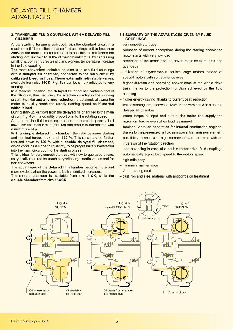
3. TRANSFLUID FLUID COUPLINGS WITH A DELAYED FILL CHAMBERA low starting torque is achieved, with the standard circuit in a maximum oil fill condition because fluid couplings limit to less than 200% of the nominal motor torque. It is possible to limit further the starting torque down to 160% of the nominal torque, by decreasing oil fill: this, contrarily creates slip and working temperature increase in the fluid coupling.The most convenient technical solution is to use fluid couplings with a delayed fill chamber, connected to the main circuit by calibrated bleed orifices. These externally adjustable valves, available from size 15CK (Fig. 4b), can be simply adjusted to vary starting time.In a standstill position, the delayed fill chamber contains part of the filling oil, thus reducing the effective quantity in the working circuit (Fig. 4a) and a torque reduction is obtained, allowing the motor to quickly reach the steady running speed as if started without load.During start-up, oil flows from the delayed fill chamber to the main circuit (Fig. 4b) in a quantity proportional to the rotating speed.As soon as the fluid coupling reaches the nominal speed, all oil flows into the main circuit (Fig. 4c) and torque is transmitted with a minimum slip.With a simple delayed fill chamber, the ratio between starting and nominal torque may reach 150 %. This ratio may be further reduced down to 120 % with a double delayed fill chamber, which contains a higher oil quantity, to be progressively transferred into the main circuit during the starting phase.This is ideal for very smooth start-ups with low torque absorptions, as typically required for machinery with large inertia values and for belt conveyors.The advantages of the delayed fill chamber become more and more evident when the power to be transmitted increases.The simple chamber is available from size 11CK, while the double chamber from size 15CCK.
3.1 SUMMARY OF THE ADVANTAGES GIVEN BY FLUID COUPLINGS– very smooth start-ups– reduction of current absorptions during the starting phase: the
motor starts with very low load– protection of the motor and the driven machine from jams and
overloads– utilization of asynchronous squirrel cage motors instead of
special motors with soft starter devices– higher duration and operating convenience of the whole drive
train, thanks to the protection function achieved by the fluid coupling
– higher energy saving, thanks to current peak reduction– limited starting torque down to 120% in the versions with a double
delayed fill chamber– same torque at input and output: the motor can supply the
maximum torque even when load is jammed– torsional vibration absorption for internal combustion engines,
thanks to the presence of a fluid as a power transmission element– possibility to achieve a high number of start-ups, also with an
inversion of the rotation direction– load balancing in case of a double motor drive: fluid couplings
automatically adjust load speed to the motors speed– high efficiency– minimum maintenance– Viton rotating seals– cast iron and steel material with anticorrosion treatment
Fig. 4 aAT REST
Fig. 4 cRUNNING
Fig. 4 bACCELERATION valve
calibrated plug
Oil in reserve foruse after start
Oil availablefor initial start
Oil drains from chamberinto main circuit All oil in circuit

Fluid couplings - 1605
STANDARD ORREVERSE MOUNTING
6
4. INSTALLATION
4.1 STAMDARD MOUNTINGDriver inner impeller
4.2 REVERSE MOUNITNGDriver outer impeller
Minimum possible inertia is added to the motor, and therefore free to accelerate more quickly.
During the starting phase, the outer impeller gradually reaches the steady running condition. For very long starting times, heat dissipation capacity is lower.If a braking system is required, it is convenient and easy to install a brake drum or disc on the flex coupling.
In some cases, where the driven machine cannot be rotated by hand, maintenance procedures of oil checking and refilling, as well as alignment, become more difficult.The delayed fill chamber, when present, is fitted on the driven side. The rotating speed of the said chamber gradually increases during start-up, thus leading to a longer starting time, assuming the bleed orifices diameters are not changed. If oil quantity is excessively reduced, the transmissible torque may be lower than the starting torque of the driven machine. In such a case, part of the oil remains inside the delayed chamber. This lack of oil in the fluid coupling may cause stalling.
The “switching pin” device might not work correctly on machines where, owing to irregular operating conditions, the driven side may suddenly stop or jam during the starting phase.
Flex coupling is protected by the placement of the fluid coupling before it, and therefore this configuration is fit for applications with frequent start-ups or inversions of the rotating sense.
Higher inertia directly connected to the motor.
The outer impeller, being directly connected to the motor, reaches synchronous speed instantly. Ventilation is therefore maximum from the beginning.
The assembly of a brake disc or drum on KR fluid couplings is more difficult, expensive and leads to a longer axial length of the whole machine group.
The outer impeller and cover are connected to the motor, it is therefore possible to manually rotate the coupling to check alignment and oil level, and for refilling.
The delayed fill chamber is fitted on the driver side, and reaches the synchronous speed in a few seconds.Oil is therefore centrifuged into the main circuit gradually and completely.Starting time is adjustable by replacing the calibrated bleed orifices.The starting phase, however is performed in a shorter time than in the configuration with an inner driver impeller.
The switching pin operation is always assured, where fitted, as the outer impeller, always rotates because it is mounted on the driver shaft.
In case of frequent start-ups or inversions of the rotating direction, the flex coupling is much more stressed.
If not expressely required by the customer or needed for the application being performed, the fluid coupling is supplied according to our “standard” mounting. Do specify in your request for quotation whether you need a “reverse” mounting.
NOTE: Starting from size 13K and 11CK included, a baffle ring is always fitted on the driver impeller, and therefore it is not ecommended to mount a fluid coupling “reverse” if “standard” mounting, or viceversa.
In these cases contact TRANSFLUID for more detailed information.

Fluid couplings - 1605
PRODUCTION PROGRAM
7
5.1 IN LINE
KRG-CKRG-CCKRG KRB-CKRB-CCKRB KRD-CKRD-CCKRD
KRG3-CKRG3-CCKRG3KRM-CKRM-CCKRM EK
KCG-CKCG-CCKCG KDM-CKDM-CCKDM
: coupling with elastic coupling. : KRG version, with brake drum (...KRB) or disc (...KRBP). : ..KR with output shaft. A flexible coupling has to be used; it is possible to place it (with a convenient housing) between the motor and a hollow shaft gearbox.: version with elastic coupling allowing removal of rubber elements without moving the machines.: coupling with clamp type, super elastic coupling. : fluid coupling fitted with a bell housing, to be placed between a flanged electric motor and a hollow shaft gearbox. : fluid coupling with gear couplings, also available with brake drum (...KCGB) or disc (...KCGBP). : fluid cou-pling with disc couplings, also available with brake drum (...KDMB) or disc (...KDMBP).
5.1 PULLEY
KSD–CKSD–CCKSD
KSI-CKSI
KSDF-CKSDF-CCKS..
: basic coupling foreseen for a flanged pulley, with simple (CK..) or double (CCK..) delayed fill chamber.
: fluid coupling with an incorporated pulley, which is fitted from inside.
: KSD coupling with flanged pulley, externally mounted and therefore to be easily disassembled.
N.B.: The ..KCG - ..KDM versions allow a radial disassembly without moving the motor or the driven machine.
5. VERSIONS KRG
CKRG - CCKRG CKRG3 - CCKRG3
CKRD - CCKRD
CKCG - CCKCG CKDM - CCKDM CKDMBP - CCKDMBP
EK
CKRBP - CCKRBP CKRBP3 - CCKRBP3
KRG3
KRD
KCG
KSD KDM KSDF
KDMB
KRB KRB3
CKSD - CCKSD CKSI CKSDF - CCKSDF

Fluid couplings - 1605
PRODUCTION PROGRAM
8
6 MOUNTING6.1 IN LINE VERSIONS MOUNTING
EXAMPLES
Fig. A
Fig. B
Fig. C
Fig. D
Fig. E
Fig. FFig. G
Horizontal axis between the motor and the driven machine (KRG-CKRG-CCKRG and similar).It allows a radial disassembly without moving the motor and the driven machine (KCG-KDM and similar).Between a flanged electric motor and a hollow shaft gearbox by means of a bell housing (..KRD and EK).Vertical axis mounting between the electric motor and a gearbox or driven machine.In case of order, please specify mounting type 1 or 2.Between the motor and a upported pulley for high powersand heavy radial loads.
Horizontal axisVertical axis. When ordering, please specify mounting tupe 1 or 2.
N.B. Version EK (fig. C) also for vertical mounting (fig. D 1-2)
6.2 PULLEY VERSIONS MOUNTING EXAMPLES
7 SPECIAL VERSION7.1 ATEXIt is possible to get the Transfluid fluid couplings with finished bores certified as equipment for intended use in hazardous zones according to directive 2014/34/EU (Atex).The selection of suitable Atex fluid coupling must consider an additional safety factor of 1.2 times the absorbed power (for instance, motor 132 kW @ 1500 rpm-absorbed power 120 kW x 1.2 = 144 kW power to be considered in the selection).According to different categories, there is the suitable selected fluid coupling as per below table.
In case of inquiry for Atex fluid coupling, you have to apply Transfluid providing the application formTF 6413 duly filled up. About KXG and KXD couplings, please refer to catalogue 160 GB.
7.2 WATER FILL FLUID COUPLINGTransfluid has developed a version of water fill fluid coupling in order to meet the demands of environment friendly products as well as cou-plings suitable for working in hazardous zone and underground mines.
7.3 LOW TEMPERATURE (below -20°C)KDM - KCG - Special bearings
- Special seal fluid.
The water to be used is a mixture of water and glycole. The water fill couplings are available upon request on all design from size 13 upwards; they have the same overall dimensions of standard couplings series. A suffix “W” identifies the coupling suitable for treated water operation (e.g. 27 CKRGW)
Fluid coupling
model
Category 3Atex Zone 2 or 22Ex II 3 D or GT4
Category 2Atex Zone 1 or 21Ex II 2 D or GT4
Category 1M2 industrialAtex E x L M2
...KRG ● ● ●
...KCG ● ●
...KDM ● ● ●
...KXG ● ●
...KXD ● ● ●...EK ●
...KBM ● ●...KSD ●
Fluid fill Oil or Treatedwater
Fire resistant oil Treated water
Treated water only
Fig. A
Fig. C
Fig. E
Fig. F
Fig. G
1 2
Fig. B
Fig. D

Fluid couplings - 1605
SELECTION
9
GENERAL REFERENCE HORSE POWER CHART
kW
Tab. A
HP
HO
RSE
PO
WER
INPUT SPEED RPM
THE CURVES SHOW LIMIT CAPACITY OF COUPLING
8 SELECTION8.1 SELECTION CHARTThe chart below may be used to select a unit size from the horse-power and input speed. If the selection point falls on a size limit line dividing one size from the other, it is advisable to select the larger size with a proportionally reduced oil fill.

Fluid couplings - 1605
SELECTION
10
8.2 SELECTION TABLE
Fluid coupling for standard electric motors.
Tab. B
MOTOR
TYPE SHAFTDIA.
80 19
90S 24
90L 24
100L 28
112M 28
132 38
132M 38
160M 42
160L 42
180M 48
180L 48
200L 55
225S 60
225M 55(300)60
250M 60 (3000)65
280S 65 (3000)75
280M 65 (3000)75
315S 65 (3000)80
315M 65 (3000)80
355S 80 (3000)100
355M 80 (3000)100
3000 rpm
kW HP COUPLING
0.751.1
11.5
7 K (1)
1.5 2
2.2 3
3 4
4 5.5
5.57.5
7.510
7.5 10
1115
1520
9 K (1)18.5 25
22 30
- - -3037
4050 11 K (1)
- - -
45 60 11 K (1)
55 75 13 K (1)
75 100
13 K (1)90 125
110 150
132160
180220 -
200 270 -
250 340 -
(°) 1800 rpm
kW HP COUPLING
0.550.75
0.751
7 K1.1 1.5
1.5 2
2.23
34
4 5.58 K
5.5 7.5
7.5 109 K
11 15
15 20 11 K
18.5 25 12 K(11 K)
22 30 12 K
30 40 13 K(12 K)
37 5013 K
45 60
55 75 15 K
75 100 17 K(15 K)
90 12517 K
110 150
132160200
180220270
19 K
260 340 21 K
315 430 24 K
1500 rpm
kW HP COUPLING
0.550.75
0.751
7 K1.1 1.5
1.5 2
2.23
34
4 5.5 8 K
5.5 7.59 K
7.5 10
11 1511 K
15 20
18.5 2512 K
22 30
30 4013 K
37 50
45 6015 K
55 75
75 10017 K
90 125
110 150 19 K132160200
180220270 21 K
250 34024 K
315 430
(°) 1200 rpm
kW HP COUPLING
0.370.55
0.50.75 7 K
0.75 1
1.1 1.5
8 K1.5 2
2.2 3
3 4 9 K
45.5
5.57.5 11 K
7.5 1012 K
11 15
- - -
15 20 13 K18.522
2530
- -15 K
30 40
37 50
17 K45 60
55 75
75 100 19 K
90110132
125150180
21 K
160 220 24 K
200250
270340 27 K
1000 rpm
kW HP COUPLING
0.370.55
0.50.75 7 K
0.75 18 K
1.1 1.5
1.5 2 9 K
2.2 3
11 K3 4
45.5
5.57.5
12 K7.5 10
11 15 13 K
- - -
15 2015 K18.5
222530
- - -
30 40 17 K
37 50
19 K45 60
55 7521 K
75 100
90110132
125150180
24 K
160 220 27 K
200250
270340 29 K
NO - STANDARDMOTORS
700 952 27 K
1000 1360 29 K
510 700 27 K
810 1100 29 K
1300 1740 34 K
1840 2500 D 34 K
440 598 29 K
800 1088 34 K
1250 1700 D 34 K
2000 2700 46 K
2500 3400 D 46 K
370 500 29 K
600 800 34 K
880 1200 D 34 K
1470 2000 46 K
2000 2700 D 46 K
max. max. max.
(°) POWERS REFER TO MOTORS CONNECTED AT 440 V. 60 HZ(1) SPECIAL VERSION, 24 HOURS SERVICE(2) ONLY FOR KRMNB: THE FLUID COUPLING SIZE IS TIED TO THE MOTOR SHAFT DIMENSIONS

Fluid couplings - 1605
SELECTION
11
8.3 PERFORMANCE CALCULTIONSFor frequent starts or high inertia acceleration, it is necessary to first carry out the following calculations. For this purpose it is necessary to know:
B) Max allowable temperature.For simplicity of calculation, ignore the heat dissipated during acceleration.Coupling temperature rise during start-up is given by:
C) Max working cycles per hour HIn addition to the heat generated in the coupling by slip during steady running, heat is also generated (as calculated above) during the acceleration period. To allow time for this heat to be dissipated, one must not exceed the max allowable number of acceleration cycles per hour.
Q = heat generated during acceleration (kcal)C = total thermal capacity (metal and oil) of coupling
selected from Tab. C (kcal/°C).
Tf = final temperature (°C)T = ambient temperature (°C)Ta = temperature rise during acceleration (°C)TL = temperature during steady running (°C)
The final coupling temperature reached at the end of the acceleration cycle will be:
Tf = T + Ta + TL (°C)
where:
The preliminary selection will be made from the selection graph Tab. A depending upon input power and speed. Then check:
A) acceleration timeB) max allowable temperatureC) max working cycles per hour
A) Acceleration time ta :
ta =
nu = nm .
Jr = J .
(sec) where:
nuJrMa
= coupling output speed (rpm)= inertia of driven machine feddered to coupling shaft (kgm2)= acceleration torque (Nm)
nu . Jr
100 - S
nL
PD2
9550 . Pm
9550 . PL
GD2
9.55 . Ma
100
nu
4
Nm
Nu
4
PmnmPLnLJT
- input power- input speed- power absorbed by the load at rated speed- speed of driven machine- inertia of driven machine- ambient temperature
kWrpmkWrpmkgm2
°C
(
(
)
)2
where S is the percent slip derived from the characteristic curvesof the coupling with respect to the absorbed torque ML.
If S is not known accurately, the following assumptions maybe made for initial calculations:4 up to size 13”3 from size 15” up to size 19”2 for all larger sizes.
Note:
Ma = 1.65 Mm - ML
where: Mm =
ML =
(Nominal Torque)
(Absorbed Torque)
J = or
Ta =
where:
(°C)QC
Q = . (kcal)Jr . nu ML . tanu76.5 8104 ( )+
TL = 2.4 .
H max =
tL = 103 . (sec)
where tL = minimum working time
(°C)PL . S
3600
Q
K
ta + tL
K = factor from Tab. DTf = must not exceed 150°C
where:
ta2
+ TL . K( )

Fluid couplings - 1605
SELECTION
12
Tab. CTHERMAL CAPACITY
8.4 CALCULATION EXAMPLEAssuming:
A) Acceleration timeFrom curve Tf 5078-X (supplied on request) slip S = 4%
B) Max allowable temperature
C) Max working cycles per hour
nu = 1450 .
Jr = 350 .
Mm =
ML =
ta =
ML = 1,65 . 131- 82 = 134 Nm
= 1392 rpm
= 88.5 kgm2
= 131 Nm
= 82 Nm
= 96 sec
100 - 4
700
9550 . 20
9550 . 12
1392 . 88.5
100
1392
1450
1392
9.55 . 134
(
(
)
)2
tL = 103 . = 724 sec361862
+ 13 . 8.9( )
Pm = 20 kWPL = 12 kWJ = 350 kgm2
T = 25 °C
nm = 1450 giri/minnL = 700 giri/min
Trasmission via belts.From selection graph. on Tab. A, selected size is 12K.
Q = .
Ta =
TL = 2.4 .
= 86 °C
= 13 °C
C = 4.2 kcal/°C (Tab.C)
K = 8.9 (Tab. D)
Tf = 25 + 86 + 13 = 124 °C
= 361 kcal88.5 . 1392 82 . 961392
361
12 . 4
76.5 8104
4.2
8.9
( )+
H = = 4 starts per hour3600
96 + 724
Kkcal/°C
CKkcal/°C
CCKkcal/°C
7 1.2-
-
8 1.59 2.511 3.2 3.712 4.2 513 6 6.815 9 10 10.317 12.8 14.6 15.819 15.4 17.3 19.421 21.8 25.4 27.524 29 32 33.827 43 50 53.929 56 63 66.634 92 99 101
D34 138 - -46 - - 175
D46 332 - -
size
OUTPUT SPEED rpm
FAC
TOR
K
Tab. DFACTOR K

Fluid couplings - 1605
SERIES 7 ÷ 19 - KRG - KRB - KRBP - CK... - CCK...
13
9. DIMENSION
KRB(with brake drum)
KRBP(with brake drum)
taper bush cylindrical bore
DIMENSIONS ARE SUBJECT TO ALTERNATION WITHPOUT NOTICE
In case of installation on shafts without shoulders, please contact Transfluid
– D BORES RELATIVE TO TAPER BUSHES WITH A KEYWAY ACCORDING TO ISO 773 - DIN 6885/1 PARTICULAR CASES:• CYLINDRICAL BORE WITHOUT TAPER BUSH WITH A KEYWAY ISO 773 - DIN 6885/1•• CYLINDRICAL BORE WITHOUT TAPER BUSH, WITH A REDUCED KEYWAY (DIN 6885/2)••• TAPER BUSH WITHOUT KEYWAY– FOR …KRB - KRBP SERIES SPECIFY X AND Y OR X1 AND Y1 DIAMETER EXAMPLE: 9KRB - D38 - BRAKE DRUM = 160x60
C1
C2
B2
I
B1
D J J1 A BKR...
B1CKR...
B2CCKR...
CKRG
C1CKRG
C2CCKRG
E F Gmax
H I K L P Q R S V Z Flexcoupling
brakedrumX - Y
brakedrumX1 - Y1
Weight kg(without oil)
KRG CKRG CCKRG
Oil max (l)
KRG CKRG CCKRG
719 24
69
40 50228 77
-
-
189
-
-
22
114 42 110
-
2
60 70 M12
27 35 M6 M8
21
-
BT 10 160 - 60
on request
8.3
-
-
0.92
-
-
28 60 40 M10
824 50
256 91 194 1836 M8
8.7 1.528 60 41 M10
928 38
111
60 80295 96 246 31
128
55 132
80
85 M20
43 54 M10 M12
27 BT 20 160 - 60200 - 75
16 1.9542●●● 48●●● 80 110 79 M16
1128 38 60 80
325 107 68.5
255
301 27 19542 56 M10 M12
18 20.5 2.75 3.3542●●● 48●●● 80 110 83 M16
1228 38 60 80
372 122
75
322 24 145
224
42 56 M10 M1221.5 24.5 4.1 4.8
42●●● 48●●● 80 110 83 M16
1342 48
143110
398 137 285 345 28 179 70
170
100
M27
84 M16
34
5 BT 30 200 - 75250 - 95
400 - 30450 - 30 34 37 5.2 5.8
55●●● 60●●● 110 58.5
3
74 104 M20
1548 55
145110
460 151 87 137 343 411 461 35 206 80 259 110 12080 70 M16 M20
35 BT40 250 - 95315 - 118
400 - 30450 - 30 50.3 54.3 62 7.65 8.6 9.3
60 65●●● 140 100 M20
1748 55
145110
520 170
96 176 362 442 522
37
225 90 250 337 110 135
80 M16 M20
34 15 BT 50 315 - 118400 - 150
445 - 30450 - 30
77 83 92 11.7 13.6 14.960 65●●● 140 103M20
75● 80● - 140 170 103 133
1948 55
145110
565 190 17
80 M16 M20
83 90 99 14.2 16.5 18.560 65●●● 140 103M20
75● 80● - 140 170 103 133
Siz
e Dimensions
KRG CKRG - CCKRG

Fluid couplings - 1605
SERIES 7 ÷ 19 - KRD - CKRD - CCKRD
14
NB: The arrows indicate input and output in the standard versions.
– WHEN ORDERING, SPECIFY: SIZE - MODEL - D DIAMETER– UPON REQUEST: BORE G MACHINED; G1 SPECIAL SHAFT– G1 SHAFT WITH A KEYWAY ACCORDING TO ISO 773 - DIN 6885/1
DIMENSIONS ARE SUBJECT TO ALTERATION WITHOUT NOTICE
G1j7
L1
C3 C4
C5
C3
KRD
C4
CKRD
C5
CCKRD
G1 L1
Weight kg(without oil)
KRD CKRD CCKRD
7 138
-
-
28 40
5.7
-
-
8 138 6.1
9 176 38
50
11.6
11185
231
42
13 15.5
12 252 16.7 19.7
13 212 272 48 60 26.3 29.3
15 330 298 348 60 80 40.4 44.4 52.1
17236 343 423 75 10
58.1 64.1 73.1
19 65.1 71.1 80.1
Siz
e
Dimensions
KRD CKRD - CCKRD

Fluid couplings - 1605
SERIES 21 ÷ 34 - KRG - KRB - KRBP - CK... - CCK...
15
NB: The arrows indicate input and output in the standard versions.
DIMENSIONS ARE SUBJECT TO ALTERATION WITHOUT NOTICE
– D BORES WITH A KEYWAY ACCORDING TO ISO 773 - DIN 6885/1• STANDARD DIMENSIONS WITH A KEYWAY ISO 773 - DIN 6885/1•• STANDARD DIMENSIONS WITH REDUCED KEYWAY (DIN 6885/2)– WHEN ORDERING, SPECIFY: SIZE - MODEL - D DIAMETER FOR …KRB OR …KRBP, SPECIFY X AND Y OR X1 AND Y1 DIMENSIONS BRAKE
DRUM OR DISC– UPON REQUEST, G FINISHED BORE EXAMPLE: 19KRBP - D80 - BRAKE DISC 450 x 30
KRB(with brake drum)
KRBP(with brake drum)
C1
C2
B2
I
B1
D J A BKR...
B1
CKR...B2
CCKR...C
KR...C1
CKR...C2
CCKR...E F G H I K L P Q R S V Z Flex
coupling
Brake drumX - Y
Brake disc
X1 - Y1
Weight kg(without oil)
KRG CKRG CCKRG
Oilmax l
KRG CKRG CCKRG
21●80 90 170
620 205
110 200
433 533 623 45
250 110 290 400 3 140 170 M36
130 M20 M24
40 45 BT60400 - 150
500 - 190
560 - 30630 - 30710 - 30795 - 30
129 139 147 19 23 31●●100 210 468 568 658 80 165 M24
24●80 90 170
714 229433 533 623 21 130 M20 M24
147 157 165 28.4 23 39●●100 210 468 568 658 56 165 M24
27 120 max 210max 780 278
131 231
484 602 702 6 315
130 354
537
4 150 200
M45
167 M24
(for max bore)-
20 BT80 500 - 190710 - 30
795 - 30
228 246 265 42 31.2 61
29 135 max 240max 860 295 513 631 731 18 350
167 M24
(for max bore)- 281 299 309 55 50 73
34 150 max 265max 1000 368 638 749 849 19 400 140 395 5 170 220
200 M36
(for max bore)- 18 BT90 630 - 236 1000 - 30 472 482 496 82.5 92.5 101
Siz
e
Dimensions
KRG CKRG - CCKRG
Fluid couplings - 1605
SERIES 21 ÷ 34 - KRD - CKRD - CCKRD
16
NB: The arrows indicate input and output in the standard versions.
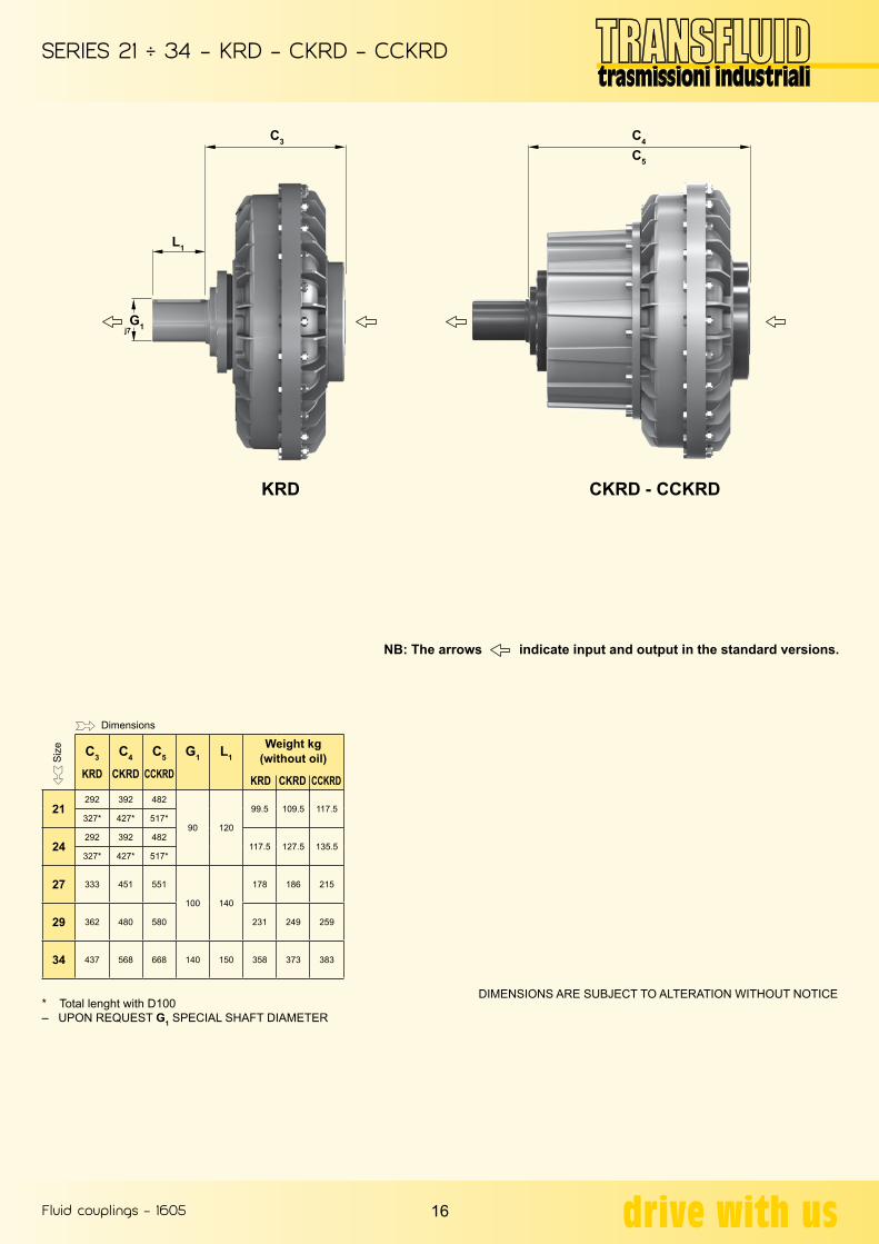
DIMENSIONS ARE SUBJECT TO ALTERATION WITHOUT NOTICE* Total lenght with D100– UPON REQUEST G1 SPECIAL SHAFT DIAMETER
G1j7
L1
C3 C4
C5
C3
KRD
C4
CKRD
C5
CCKRD
G1 L1Weight kg
(without oil)
KRD CKRD CCKRD
21292 392 482
90 120
99.5 109.5 117.5327* 427* 517*
24292 392 482
117.5 127.5 135.5327* 427* 517*
27 333 451 551
100 140
178 186 215
29 362 480 580 231 249 259
34 437 568 668 140 150 358 373 383
Siz
e
Dimensions
KRD CKRD - CCKRD

Fluid couplings - 1605
SERIES 17 ÷ 46 - KRG3 - KRBP - CK... - CCK...
17
The three pieces flexible coupling B3T, allows the removal of the elastic elements (rubber blocks), without removal of the electricmotor; only with the ..KRB3 (with brake drum) coupling the electric motor must be removed by the value of ‘Y’.‘Y’ = axial displacement male part of the coupling B3T necessary for the removal of the elastic elements.
– D BORES RELEVANT TO TAPER BUSH WITH KEYWAY ACCORDING TO ISO773 - DIN6885/1• STANDARD CYLINDRICAL BORES WITHOUT TAPER BUSH WITH KEYWAY ACCORDING TO ISO773 - DIN6885/1••• TAPER BUSH WITHOUT KEYWAY
– D CYLINDRICAL BORES WITHOUT TAPER BUSH WITH KEYWAY ACCORDING TO ISO773 – DIN6885/1• STANDARD DIMENSIONS•• STANDARD DIMENSION WITH REDUCED HIGH KEYWAY (DIN 6885/2)– ON ORDER FORM PLEASE SPECIFY: DIMENSION, MODEL, DIAMETER D - EXAMPLE: 21CCKRG3 - D80
DIMENSIONS ARE SUBJECT TO ALTERATION WITHOUT NOTICE
C1
C2
(only for 17-19)
D J J1 A C C1 C2 G H K L L1 P R S Y Elasticcoupling
Weight kg(without oil)
KRG3 CKRG3 CCKRG3
1748 55
145110
520
418 498 578 90 240 3 110 82 130
80 M16 M20
82 B3T-50
84 90 9960 65●●● 140 103M20
75● 80● - 140 - 170 103 132
1948 55
145110
565
80 M16 M20
91 97 10660 65●●● 140 103M20
75● 80● - 140 - 170 103 132
Siz
e
Dimensions
2180● 90 170
-
620457 557 647
110 290 3 140 78 150
130 M20 M24
82 B3T-60
134 144 152100●● 210 492 592 682 165 M24
2480● 90 170
714457 557 647 130 M20 M24
152 162 170100●● 210 492 592 682 165 M24
27 120 max 210 780 566 684 784
130 354 4 150 112 180
167 M24
120 B3T-80
247 265 284
29 135 max 240 860 595 713 813 for max hole 300 318 328
34 150 max 265 1000 704 815 915 150 395 5 170 119 205 200 M36for max hole 151 B3T-90 505 481 491
46 180 max 320 - 1330 - - 1092 180 490 7 195 138 270 190 M36for max hole 122 B3T-100 - - 1102
CKRG3 - CCKRG3KRG3
KRB3(with brake drum)
KRBP3(with brake disc)
Fluid couplings - 1605
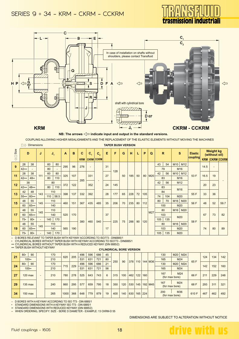
SERIES 9 ÷ 34 - KRM - CKRM - CCKRM
18
COUPLING ALLOWING HIGHER MISALIGNMENTS AND THE REPLACEMENT OF THE ELASTIC ELEMENTS WITHOUT MOVING THE MACHINES
TAPER BUSH VERSION
CYLINDRICAL BORE VERSION
– D BORES RELEVANT TO TAPER BUSH WITH KEYWAY ACCORDING TO ISO773 - DIN6885/1• CYLINDRICAL BORES WITHOUT TAPER BUSH WITH KEYWAY ACCORDING TO ISO773 - DIN6885/1••• CYLINDRICAL BORES WITHOUT TAPER BUSH WITH A REDUCED KEYWAY (DIN 6885/2)••• TAPER BUSH WITHOUT KEYWAY
– D BORES WITH A KEYWAY ACCORDING TO ISO 773 - DIN 6885/1• STANDARD DIMENSIONS WITH A KEYWAY ISO 773 - DIN 6885/1•• STANDARD DIMENSIONS WITH REDUCED KEYWAY (DIN 6885/2)– WHEN ORDERING, SPECIFY: SIZE - SERIE D DIAMETER - EXAMPLE: 13 CKRM-D 55
DIMENSIONS ARE SUBJECT TO ALTERATION WITHOUT NOTICE
NB: The arrows indicate input and output in the standard versions.
C1
C2
Siz
e
Dimensions
D J J1 A B C
KRM
C1
CKRM
C2
CCKRM
E F G H L P Q R S Elasticcoupling
Weight kg(without oil)
KRM CKRM CCKRM
928 38
111
60 80295 96 276 -
-
31128
50 185 50 80 M20
43 54 M10 M12
53 F
14.5 -
-
42●●● - 80 - 79 M16
1128 38 60 80
325 107285
331 2742 56 M10 M12
16.5 1942●●● 48●● 80 110 83 M16
1238 80
372 122 352 24 14542 56 M12
20 2342●●● 48●●● 80 110 83
M16
1342 48
143110
398 137 332 392 28 177 65 228 72 105
M27
8455 F 33 36
55●●● 60●●● 110 58.5 74 104 M20
1548 55
145110
460 151 367 435 485 35 206 70 235 80 11280 70 M16 M20
56 F 48 52 59.760 65●●● 140 100 M20
1748 55
145110
520 170
380 460 540
37
225 75 288 90 120
80 M16 M20
58 F
67 73 8260 65●●● 140 103M20
75● 80● - 140 170 105 135
1948 55
145110
565 190 1780 M16 M20
74 80 8960 65●●● 140 103 M2075● 80● - 140 170 105 135 M20
2180● 90
-
170620 205
496 596 686 45
250 90 378 110 144 M36
130 M20 M24
65 F124 134 142
100●● 210 531 631 721 80 165 M24
2480● 90 170
715 229496 596 686 21 130 M20 M24
142 152 160100●● 210 531 631 721 56 165 M24
27 120 max 210 780 278 525 643 743 6 315 100 462 122 160
M45
167 M24(for max bore) 66 F 211 229 248
29 135 max 240 860 295 577 659 795 18 350 120 530 145 192 167 M24(for max bore) 68 F 293 311 321
34 150 max 265 1000 368 648 779 879 19 400 140 630 165 224 200 M36(for max bore) 610 F 467 462 492
CKRM - CCKRMKRM
In case of installation on shafts without shoulders, please contact Transfluid
shaft with cylindrical bore
Fluid couplings - 1605
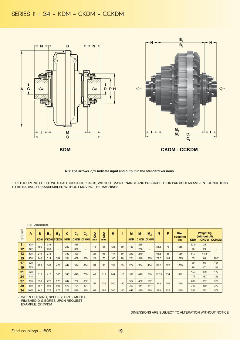
SERIES 11 ÷ 34 - KDM - CKDM - CCKDM
19
NB: The arrows indicate input and output in the standard versions.
FLUID COUPLING FITTED WITH HALF DISC COUPLINGS, WITHOUT MAINTENANCE AND PRSCRIBED FOR PARTICULAR AMBIENT CONDITIONS. TO BE RADIALLY DISASSEMBLED WITHOUT MOVING THE MACHINES.
DIMENSIONS ARE SUBJECT TO ALTERATION WITHOUT NOTICE
- WHEN ODERING, SPECIFY: SIZE - MODEL- FIMISHED D-G BORES UPON REQUEST EXAMPLE: 27 CKDM
B1
B2N N
M1
C1M2
C2
I I
A B
KDM
B1CKDM
B2CCKDM
C
KDM
C1CKDM
C2CCKDM
DG
min
DG
max
H I M
KDM
M1CKDM
M2CCKDM
N P Disccoupling
size
Weight kg(without oil)
KDM CKDM CCKDM11 325
186232
-289
335
-16 55 123 50 189
235
-51.5 76 1055
22.5 25
-12 372 253 356 256 26 29
13 398 216 276 339 399 21 65 147 60 219 279 61.5 88 1065 41.3 44.3
15 460 246 314 364 391 459 509 21 75 166 70 251 319 369 72.5 104 1075 65 69 76.7
17 520269 349 429 444 524 604 31 90 192 85 274 354 434 87.5 122 1085
89 95 104
19 565 96 102 111
21 620315 415 505 540 640 730 41 115 244 110 320 420 510 112.5 154 1110
159 169 177
24 714 177 187 195
27 780 358 476 576 644 762 86251 135 300 140
364 482 582143 196 1140
289 307 326
29 860 387 505 605 673 791 891 393 511 611 342 360 370
34 1000 442 573 673 768 899 999 61 165 340 160 448 579 679 163 228 1160 556 562 572
Siz
e
Dimensions
CKDM - CCKDMKDM

Fluid couplings - 1605
SERIES 12 ÷ 34 - KDMB - KDMBP - CKDM... - CCKDM...
20
DIMENSIONS ARE SUBJECT TO ALTERATION WITHOUT NOTICE
NB: The arrows indicate input and output in the standard versions.
– WHEN ORDERING, SPECIFY: SIZE - MODEL– D AND G1 FINISHED BORES UPON REQUEST, AND SPECIAL I1 DIMENSION– FOR BRAKE DRUM OR DISC, SPECIFY DIMENSIONS X AND Y OR X1 AND Y1 EXAMPLE : 17KDMB - BRAKE DRUM 400 x 150
KDMB(with brake drum)
KDMBP(with brake drum)
ONLY FOR 27 - 29 ARE AVAILABLE HUBS FOR BRAKE DRUM/DISC WITH CENTRAL FLANGE
Siz
e
Dimensions
Siz
e
Dimensions
BrakedrumX - Y
Brake disc
X1 - Y1
Weight kg(without oil, brake
drum and disc) KD.. CKD.. CCKD..
12200 - 75 on request
27 30-
13 42.5 45.8
15 250 - 95 450 - 30 69.3 73.3 81
17 315 - 118 500 - 30 99 105 114
19 400 - 150 560 - 30 105 112 125
21 400 - 150 630 - 30 179 189 197
24 500 - 190 710 - 30 197 207 215
27500 - 190 800 - 30
317 335 354
29 370 388 398
34 on request 800 - 301000 - 30 599 587 597
A B
KDM
B1
CKDM
B2
CCKDM
CB
KD..
CB1
CKD..
CB2
CCKDM..
D
max
G1
max
I I1 std max
MB
KD...
MB1
CKD..
MB2
CCKDM..
N N1
St
O P Q R S
÷0.1
T
f7
U
Nr. Ø
V Z Disccoupling
size12 372 186 253
-336.5 403.5
-55 60 50 80 206.5 273.5
-51.5 99 17.5 76 67 69 128 142 8
M8114
-1055
13 398 216 276 440.5 500.5 65 70 60 140170
240.5 300.5 61.5 163 21.5 88 78 129 155 170
12
140 1065
15 460 246 314 364 495.5 563.5 613.5 75 80 70 150 275.5 343.5 393.5 72.5 177 24.5 104 98 134 175 192
M10
157 109 1075
17 520269 349 429 548.5 628.5 708.5 90 95 85
160
210 303.5 383.5 463.5 87.5 192 29.5 122107
143 204 224 185 118 108519 565 87
21 620315 415 505 628.5 728.5 818.5 115 120 110
240
358.5 458.5 548.5 112.5 201 38.5 154133
137 256 276 M12 234 112 111024 714 109
27 780 358 476 576 731.5 849.5 949.5135 145 140
180
411.5 529.5 629.5143 230.5 47.5 196
107155 315 338 M14 286 133 1140
29 860 387 505 605 760.5 878.5 978.5 440.5 558.5 658.5 109
34 1000 442 573 673 845.5 976.5 1076.5 165 175 160 505.5 636.5 736.5 163 240.5 57.5 228 124 152 356 382 M16 325 130 1160

Fluid couplings - 1605
SERIES 7 ÷ 46 - KCG - KCGB - CKCGBP - CCKCG...- CCKCG
21
NB: The arrows indicate input and output in the standard versions.
FLUID COUPLING FITTED WITH HALF GEAR COUPLINGS, TO BE RADIALLYDISASSEMBLED WITHOUT MOVING THE MACHINES
Brake drum or disc upon request
• UPON REQUEST(5) E.I. = EXPOSED INCH SCREWS(6) GEAR COUPLING WITH SPECIAL CALIBRATED BOLTS– WHEN ORDERING, SPECIFY: SIZE - MODEL
EXAMPLE: 21CKCG
DIMENSIONS ARE SUBJECT TO ALTERATION WITHOUT NOTICE
C1C2
M1M2
YZ
X
X1
Z1 Y1
I
G1
A C
KCG
C1
CKCG
C2
CCKCG
DG
max
G1
max
I I1 M
KCG
M1
CKCG
M2
CCKCG
N Brakedrum X - Y
Z Brakedrum X1 - Y1
Z1 GearCouplig
Size
Weight kg(without oil)
KCG CKGC CCKCG7 228 229
-
-
50 - 43 80143
-
-
44.5 ● ● ● ●1”
E.I.(5) (6)
11.3
-
-
8 256 234 148 11.7
9 295 290.6
65 45 50 114
190.6
50.8 250-95 45 400-30 321” ½E.I.
(5) (6)
22.9
11 325 299.6 345.6199.6
245.6 24.9 27.4
12 372 299.6 366.6 266.6 28.5 31.4
13 398 325.1 385.6 225.1 285.1 37.6 40.6
15 460 410 478 528
95 65 76 146
258 326 376
79.5250-95
315-118
57.5
21.5
400-30
445-3044.5
2” ½E.I.
(5) (6)
76.6 80.6 88.3
17 520434 514 594 282 362 442
91.1 97.1 106.1
19 565 98.1 104.1 113.1
21 620503 603 693 111 90 90 165 323 423 513 93.5
315-118 26 560-30 38 3”E.I.
(5) (6)
142.3 152.3 160.3
24 714 400-150 15 710-30 38 160.3 170.3 178.3
27 780 627 754 845134 110 105 170
417 535 635109.5 500-190 6 795-30 30
3” ½E.I.
(5) (6)
253.2 272.2 291.2
29 860 656 774 874 446 564 664 307.2 325.2 335.2
34 1000 750 881 981 160 120 120 190 510 641 741 123.5 ● ● 800-30 424”
E.I.(5) (6)
492.4 507.4 517.4
46 1330 - - 1313.4 244 175 190 280 - - 933.4 192.5 ● ● ● ●6”
E.I.(5) (6)
- - 1333
Siz
e
Dimensions
CKCG - CCKCGKCG
..KCGBP(with brake disc)
..KCGB(with brake drum)

Fluid couplings - 1605
SERIES D34KBM - D46KBM - D34KDM - D34CKDM
22
FLUID COUPLING WITH DOUBLE CIRCUIT, FITTED WITH MAIN JOURNALS AND INPUT AND OUTPUT SHAFTS
FLUID COUPLING FITTED WITH HALF GEAR COUPLINGS, TO BE RADIALLYDISASSEMBLED WITHOUT MOVING THE MACHINES
FLUID COUPLINGS FITTED WITH DOUBLE CIRCUIT, TO BE RADIALLY DISASSEMBLED WITHOUT MOVING THE MACHINES.
WITH HALF DISC COUPLINGS, WITHOUT MAINTENANCE WITH HALF DISC COUPLINGS
NB: The arrows indicate input and output in the standard versions.
DIMENSIONS ARE SUBJECT TO ALTERATION WITHOUT NOTICE
g =a =b =d =d1 =
TOTAL WEIGHT INCLUDING OIL (MAX FILL)INTERNAL ELEMENTEXTERNAL ELEMENTHALF FLEXIBLE COUPLING (INTERNAL ELEMENT)HALF FLEXIBLE COUPLING (EXTERNAL ELEMENT)
165
4251093
620165
165max. 1000
1103
1423
061061
165max.
KEYWAYS ACCORDING TO ISO 773 - DIN 6885/1
SERIES A C F D-Gm6
L M N P
D34KBM 1000 1400 855 140 140 1120 257.5 170
D46KBM 1330 1900 1275 160 200 1550 312.5 170
WEIGHT Kg(Without oil)
OILmax.
l
CENTER OF GRAVITYg l
Kg mm
MOMENT OF INERTIAJ (WR2) Kgm²a b
810 162 952 710 26.19 64.25
2200 390 2514 955 91.25 183.7
WEIGHT Kg(without oil)
OILmax. l
CENTER OF GRAVITYg l
kg mm
MOMENT OF INERTIAJ (WR2) Kgm²
a b c dD34KDM 880 162 1022 512 26.08 65.53 0.955 0.955
D34CKDM 1014 194.5 194.5 532 26.08 67.99 0.955 0.955
Siz
e Dimensions
Also available D46KCG. For information please apply Transfluid
D34KBMD46KBM
D34KDM D34CKDM
Fluid couplings - 1605
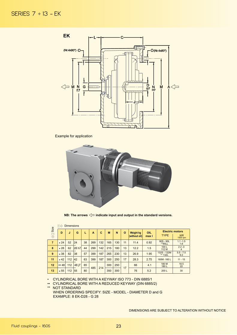
SERIES 7 ÷ 13 - EK
23
EK
Example for application
NB: The arrows indicate input and output in the standard versions.
• CYLINDRICAL BORE WITH A KEYWAY ISO 773 - DIN 6885/1•• CYLINDRICAL BORE WITH A REDUCED KEYWAY (DIN 6885/2)** NOT STANDARD
WHEN ORDERING SPECIFY: SIZE - MODEL - DIAMETER D and GEXAMPLE: 8 EK-D28 - G 28
DIMENSIONS ARE SUBJECT TO ALTERATION WITHOUT NOTICE
D J G L A C M N O Weight kg(without oil)
OILmax l
Electric motors TYPE kW
1500 rpm
7 ● 24 52 24 38 269 132 165 130 11 11.4 0.92 90S - 90L**90LL
1.1 -1.51.6
8 ● 28 62 28 h7 44 299 142 215 180 13 12.2 1.5 100 L112 M
2.2 -34
9 ● 38 82 38 57 399 187 265 230 13 26.9 1.95 132S - 132M** 132L
5.5 - 7.59.2
11 ● 42 112 42 63 399 187 300 250 17 28.3 2.75 160M -160 L 11 - 15
12 ●● 48 112 48 j7 65485 214
300 25017
66 4.1 180 M180 L
18.522
13 ● 55 112 55 80 350 300 76 5.2 200 L 30
Siz
e Dimensions
Fluid couplings - 1605
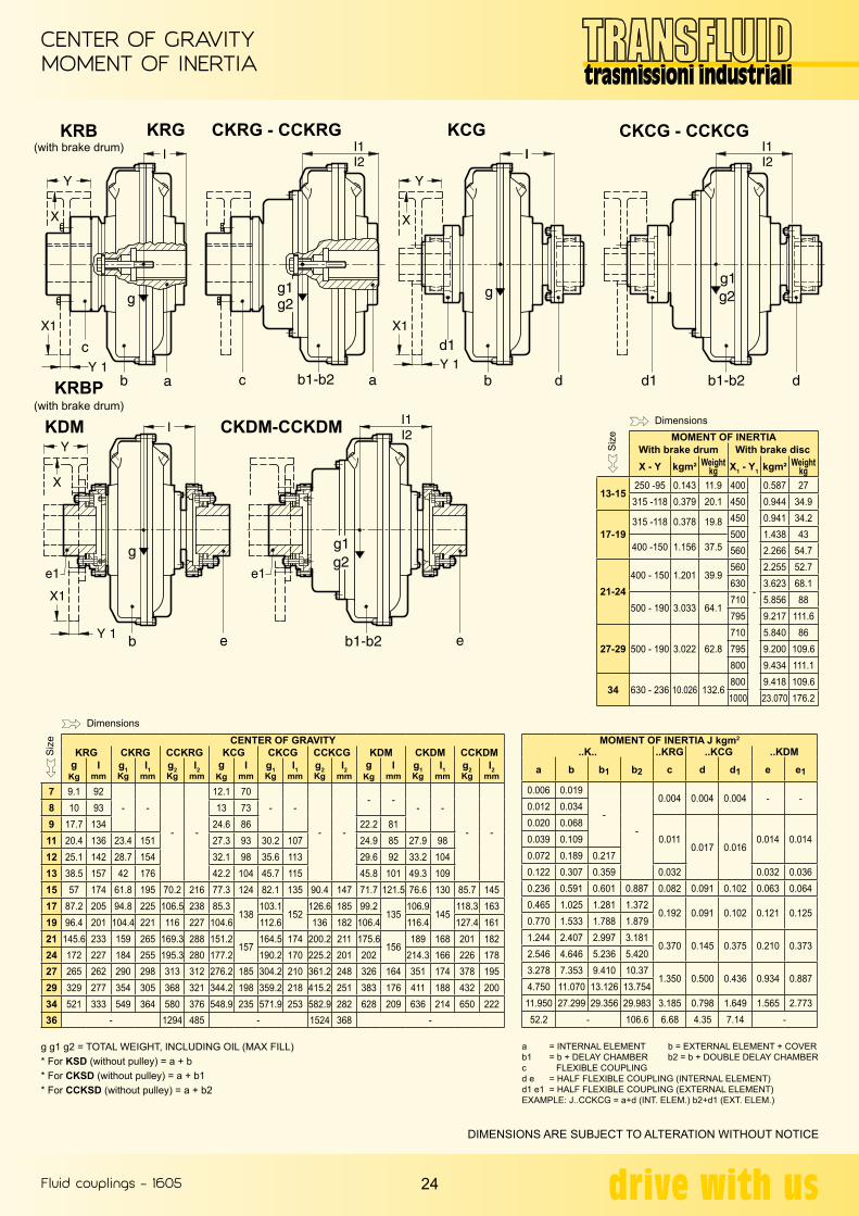
CENTER OF GRAVITYMOMENT OF INERTIA
24
g g1 g2 = TOTAL WEIGHT, INCLUDING OIL (MAX FILL)* For KSD (without pulley) = a + b* For CKSD (without pulley) = a + b1* For CCKSD (without pulley) = a + b2
a = INTERNAL ELEMENT b = EXTERNAL ELEMENT + COVERb1 = b + DELAY CHAMBER b2 = b + DOUBLE DELAY CHAMBERc FLEXIBLE COUPLINGd e = HALF FLEXIBLE COUPLING (INTERNAL ELEMENT)d1 e1 = HALF FLEXIBLE COUPLING (EXTERNAL ELEMENT)EXAMPLE: J..CCKCG = a+d (INT. ELEM.) b2+d1 (EXT. ELEM.)
DIMENSIONS ARE SUBJECT TO ALTERATION WITHOUT NOTICE
KRB(with brake drum)
KRBP(with brake drum)
KRG
KDM CKDM-CCKDM
CKRG - CCKRG KCG CKCG - CCKCG
MOMENT OF INERTIAWith brake drum With brake discX - Y kgm² Weight
kg X1 - Y1 kgm² Weightkg
13-15250 -95 0.143 11.9 400
-
0.587 27315 -118 0.379 20.1 450 0.944 34.9
17-19315 -118 0.378 19.8 450 0.941 34.2
500 1.438 43400 -150 1.156 37.5 560 2.266 54.7
21-24400 - 150 1.201 39.9
560 2.255 52.7630 3.623 68.1
500 - 190 3.033 64.1710 5.856 88795 9.217 111.6
27-29 500 - 190 3.022 62.8710 5.840 86795 9.200 109.6800 9.434 111.1
34 630 - 236 10.026 132.6800 9.418 109.61000 23.070 176.2
CENTER OF GRAVITYKRG CKRG CCKRG KCG CKCG CCKCG KDM CKDM CCKDM
gKg
Imm
g1Kg
I1mm
g2Kg
I2mm
gKg
Imm
g1Kg
I1mm
g2Kg
I2mm
gKg
Imm
g1Kg
I1mm
g2Kg
I2mm
7 9.1 92- -
- -
12.1 70- -
- -
- -- -
- -
8 10 93 13 739 17.7 134 24.6 86 22.2 8111 20.4 136 23.4 151 27.3 93 30.2 107 24.9 85 27.9 9812 25.1 142 28.7 154 32.1 98 35.6 113 29.6 92 33.2 10413 38.5 157 42 176 42.2 104 45.7 115 45.8 101 49.3 10915 57 174 61.8 195 70.2 216 77.3 124 82.1 135 90.4 147 71.7 121.5 76.6 130 85.7 14517 87.2 205 94.8 225 106.5 238 85.3
138103.1
152126.6 185 99.2
135106.9
145118.3 163
19 96.4 201 104.4 221 116 227 104.6 112.6 136 182 106.4 116.4 127.4 16121 145.6 233 159 265 169.3 288 151.2
157164.5 174 200.2 211 175.6
156189 168 201 182
24 172 227 184 255 195.3 280 177.2 190.2 170 225.2 201 202 214.3 166 226 17827 265 262 290 298 313 312 276.2 185 304.2 210 361.2 248 326 164 351 174 378 19529 329 277 354 305 368 321 344.2 198 359.2 218 415.2 251 383 176 411 188 432 20034 521 333 549 364 580 376 548.9 235 571.9 253 582.9 282 628 209 636 214 650 22236 - 1294 485 - 1524 368 -
MOMENT OF INERTIA J kgm2
..K.. ..KRG ..KCG ..KDM
a b b1 b2 c d d1 e e1
0.006 0.019
--
0.004 0.004 0.004 - -0.012 0.0340.020 0.068
0.0110.017 0.016
0.014 0.0140.039 0.1090.072 0.189 0.2170.122 0.307 0.359 0.032 0.032 0.0360.236 0.591 0.601 0.887 0.082 0.091 0.102 0.063 0.0640.465 1.025 1.281 1.372
0.192 0.091 0.102 0.121 0.1250.770 1.533 1.788 1.8791.244 2.407 2.997 3.181
0.370 0.145 0.375 0.210 0.3732.546 4.646 5.236 5.4203.278 7.353 9.410 10.37
1.350 0.500 0.436 0.934 0.8874.750 11.070 13.126 13.75411.950 27.299 29.356 29.983 3.185 0.798 1.649 1.565 2.77352.2 - 106.6 6.68 4.35 7.14 -
Siz
e
Dimensions
Siz
e
Dimensions

Fluid couplings - 1605
SERIES 7 ÷ 27 - KSD - CKSD - CCKSD
25
NB: The arrows indicate input and output in the standard versions.
DIMENSIONS ARE SUBJECT TO ALTERATION WITHOUT NOTICE
Weight kg(without oil)
KSD CKSD CCKSD7 5.9
-
-
8 6.59 1311 15 17.512 19 2213 31 3415 46 50 57.517 74 80 8919 82 88 9721 110 120 12824 127 137 14527 184 202 221
Siz
e
Dimensions
D J J1 A B B1 B2 C C1 C2 E F G H I K L M N P Q R S T
KSD CKSD CCKSD max CKSD CCKSD Nr. Ø max
719 24
69
40 50228 77
-
-
159
-
-
55
75 90 4 M6
-
8
35
3 114 14 M1
29 38 M6 M8
5028 60 174 70 50 43 M10
824 50
256 91 194 81 6533 M8
28 60 43 M10
928 38
111
60 80295 96 250 116
96 114
8
M8 13
85 5 128 20
M20
39 61 M10 M12
69●●●42 80 78 M16
1128 38 60 80
325 107 73.5 259 289.5 113 19538 59 M10 M12
●●●42 80 78 M16
1238 42
11380 110
372 122
80
274 327 125 112 130
224
98 7 145 2254 83 M12 M16
80●●●48 110 83 M16
1342 48
144110
398 137 367 407 190 135 155
12
158 6 177 29
M27
76 M1688
●●●55 ●●●60 110 58.5 76 106 M20
1548 55
145110
460 151 92 142 390 438 488 195 150 178
M10
264 17 159
7
206 2880 70 M16 M20
10060 ●●●65 140 100 M20
1748 55
145110
520 170
101 181 455 516 596
245
180 200 337 17 180 225
60
69
M20 132
60 ●●●65 140 99
●75 ●80 - 140 170 99 139
1948 55
145110
565 190 225 45
69
60 ●●●65 140 99
●75 ●80 - 140 170 99 139
TAPER BUSH VERSION
CYLINDRICAL BORE VERSION
Siz
e
Dimensions
– D BORES RELATIVE TO TAPER BUSHES WITH A KEYWAY ACCORDING TO ISO 773 - DIN 6885/1 PARTICUALR CASES:• CYLINDRICAL BORE WITHOUT TAPER BUSH ISO 773 - DIN 6885/1••• TAPER BUSH WITHOUT A KEYWAY
• STANDARD CYLINDRICAL BORES WITH KEYWAYS ACCORDING TO ISO 773 - DIN 6885/1– WHEN ORDERING SPECIFY: SIZE - MODEL - D DIAMETER EXAMPLE: 12KSD - D 42
21●80
-
170620 205
115 205
505 580 670 260
200 228 8 M14 400 23
190
7 250
57
M36
135 M20
145●100 210 545 620 710 300 230 165 M24
24●80 170
714 229505 580 670 236 190
M36135 M20
●100 210 545 620 710 276 230 165 M24
27 120 max 210 780 278 138 CONSULT OUR ENGINEERS
KSD
CKSD-CCKSD
cylindrical bore without taperbush(see tab. below)
taper bush
In case of installation on shafts without shoulders, please contact Transfluid

Fluid couplings - 1605
STANDARD PULLEYS
26
DIMENSIONS ARE SUBJECT TO ALTERATION WITHOUT NOTICE
DPD
UV Z
D U
Flanged pulley
Dp N° type
719 - 24 6
1252 - SPA/A28 21
8 19 - 2428
36 1259 112 3 - SPA/A
911
28 - 3842
34 160 4 - SPB/B58 200 3 - SPB/B
12 38 - 4248
50 180 4 - SPB/B51
200 3 - SPC/C
26 4 - SPC/C
13 42 - 4855 - 60
12.5 180 6 - SPB/B5049 250 6 - SPB/B
5 - SPC/C
15 48 - 5560 - 65
12.5 200 6 - SPB/B17 250 5 - SPC/C69 280 5 - SPB/B
1719
67 - 7580
72.5 280 6 - SPB/B85.5 310 6 - SPC/C72.5 315 6 - SPB/B59 345 6 - SPC/C
2124 Upon request
27
Siz
e
Dimensions
GROOVE V Z
SPZ/Z 12 8SPA/A 15 10SPB/B 19 12.5SPC/C 25.5 17
D 37 243 V 10.3 8.75 V 17.5 12.78 V 28.6 19
D U
Integralpulley
Dp N° type
7
19 - 24 11.580
2 - SPA/A
90100
28 26.58090100
8 19 - 2428 26.5
903 - SPA/A
100911
28 - 3842
10 112 5 - SPA/A15 125 4 - SPB/B
12 38 - 4248 12 140 5 - SPB/B
Siz
e
Dimensions
– WHEN ORDERING, SPECIFY: SIZE - MODEL - D DIAMETER - Dp - NUMBER AND TYPE OF GROOVES EXAMPLE: 13 CKSDF - D55 - PULLEY Dp. 250 - 5 SPC/C
...KSI
KSI - CKSI - CCKSI
...KSDF
KSDF - CKSDF - CCKSDF
Fluid couplings - 1605
FILLINGSAFETY DEVICES - OPERATION
27
10. FILLING Transfluid hydraulic couplings are supplied without oil. Standard filling: X for K series, 2 for CK series, and 3 for CCK series.The quantities are indicated on page 13 and 15 of this catalog. Follow the procedure indicated on Installation and Maintenance manuals 150 GB and 155 GB delivered with each coupling.Suggested oil: ISO32 HM for normal operating temperatures. For temperatures down zero, ISO FD 10 (SAE 5W) and for temperatures lower than –20°C contact TRANSFLUID.
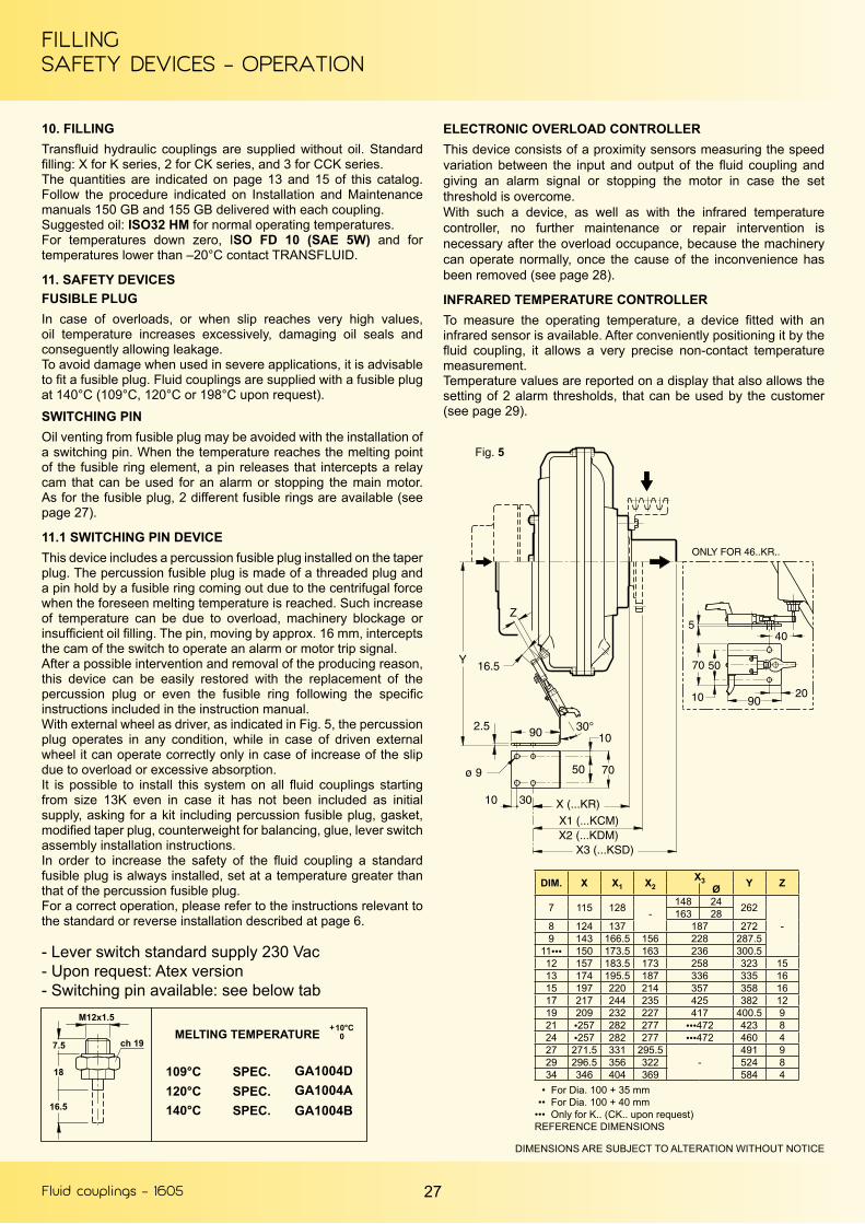
11. SAFETY DEVICESFUSIBLE PLUGIn case of overloads, or when slip reaches very high values, oil temperature increases excessively, damaging oil seals and conseguently allowing leakage.To avoid damage when used in severe applications, it is advisable to fit a fusible plug. Fluid couplings are supplied with a fusible plug at 140°C (109°C, 120°C or 198°C upon request).
SWITCHING PINOil venting from fusible plug may be avoided with the installation of a switching pin. When the temperature reaches the melting point of the fusible ring element, a pin releases that intercepts a relay cam that can be used for an alarm or stopping the main motor. As for the fusible plug, 2 different fusible rings are available (see page 27).
11.1 SWITCHING PIN DEVICEThis device includes a percussion fusible plug installed on the taper plug. The percussion fusible plug is made of a threaded plug and a pin hold by a fusible ring coming out due to the centrifugal force when the foreseen melting temperature is reached. Such increase of temperature can be due to overload, machinery blockage or insufficient oil filling. The pin, moving by approx. 16 mm, intercepts the cam of the switch to operate an alarm or motor trip signal.After a possible intervention and removal of the producing reason, this device can be easily restored with the replacement of the percussion plug or even the fusible ring following the specific instructions included in the instruction manual.With external wheel as driver, as indicated in Fig. 5, the percussion plug operates in any condition, while in case of driven external wheel it can operate correctly only in case of increase of the slip due to overload or excessive absorption.It is possible to install this system on all fluid couplings starting from size 13K even in case it has not been included as initial supply, asking for a kit including percussion fusible plug, gasket, modified taper plug, counterweight for balancing, glue, lever switch assembly installation instructions.In order to increase the safety of the fluid coupling a standard fusible plug is always installed, set at a temperature greater than that of the percussion fusible plug.For a correct operation, please refer to the instructions relevant to the standard or reverse installation described at page 6.
ELECTRONIC OVERLOAD CONTROLLERThis device consists of a proximity sensors measuring the speed variation between the input and output of the fluid coupling and giving an alarm signal or stopping the motor in case the set threshold is overcome.With such a device, as well as with the infrared temperature controller, no further maintenance or repair intervention is necessary after the overload occupance, because the machinery can operate normally, once the cause of the inconvenience has been removed (see page 28).
INFRARED TEMPERATURE CONTROLLERTo measure the operating temperature, a device fitted with an infrared sensor is available. After conveniently positioning it by the fluid coupling, it allows a very precise non-contact temperature measurement.Temperature values are reported on a display that also allows the setting of 2 alarm thresholds, that can be used by the customer (see page 29).
- Lever switch standard supply 230 Vac- Upon request: Atex version- Switching pin available: see below tab
DIMENSIONS ARE SUBJECT TO ALTERATION WITHOUT NOTICE
GA1004DGA1004AGA1004B
Fig. 5
DIM. X X1 X2X3 Y ZØ
7 115 128 -148 24 262
-163 28
8 124 137 187 2729 143 166.5 156 228 287.5
11●●● 150 173.5 163 236 300.512 157 183.5 173 258 323 1513 174 195.5 187 336 335 1615 197 220 214 357 358 1617 217 244 235 425 382 1219 209 232 227 417 400.5 921 ●257 282 277 ●●●472 423 824 ●257 282 277 ●●●472 460 427 271.5 331 295.5
-491 9
29 296.5 356 322 524 834 346 404 369 584 4
• For Dia. 100 + 35 mm •• For Dia. 100 + 40 mm••• Only for K.. (CK.. upon request)REFERENCE DIMENSIONS

Fluid couplings - 1605
SAFETY DEVICESOPERATION
28
11.2 OVERLOAD CONTROLLER (Fig. 6)When load torque increases, slip also increases and output speed consequently decreases.The said speed variation can be measured by means of a sensor sending a pulse train to the speed controller. If the rotating speed goes lower than the set threshold (see diagram) on the controller, a signal is given through the intervention of the inner relay.The device has a “TC” timer with a blind time before starting (1 - 120 s) avoiding the alarm intervention during the starting phase, and another “T” timer (1 – 30 s) preventing from undesired relay intervention during sudden changes of torque.The device also provides a speed proportional analogic output signal (0 – 10 V), that can be forwarded to a display or a signal transducer (4 – 20 mA).Standard supply is 230 V ac, other supplies are available upon request: 115 V ac, 24 V ac or 24 V dc, to be specified with the order.Atex version is available too.
CONTROLLER PANEL (Fig. 7)
TC Blind time for starting
DS Speed range regulation
SV Speed level (set point)
R Reset
SS Threshold overtaking
A Alarm led
E Enable
T Delay time
ON Supply
Set screw regulation up to 120 s
Programmable DIP-SWITCH (5 positions), selecting relay status, roximity type, reset system, acceleration or deceleration.Programming speed Dip-Switch with 8 positions allows to choose the most suitable speed range, according to the application being performed.
Set screw regulation with digits from 0 to 10. The value 10 corresponds to full range set with Dip-Switch.
Local manual reset is possible through R button, or remote resetby connecting a N.O. contact at pins 2-13.
(RED LED) It lights up every time that the set threshold (set point)is overtaken.
(RED LED) It lights up when alarm is ON and the inner relay is closed.
(YELLOW LED) It lights up when the device is enabled.
Set screw regulation up to 30 s.
(GREEN LED) It shows that the device is electrically supplied.
FOR FURTHER DETAILS, ASK FOR TF 5800-A.
ON
Diagram
ON
TIMELED
RELAY
SP
EE
D
STAR
T - U
P
OPE
RATI
ON
OVE
RLO
AD
ON
(upon request)
Fig. 6
Fig. 7
Fluid couplings - 1605 29
SAFETY DEVICESOPERATION
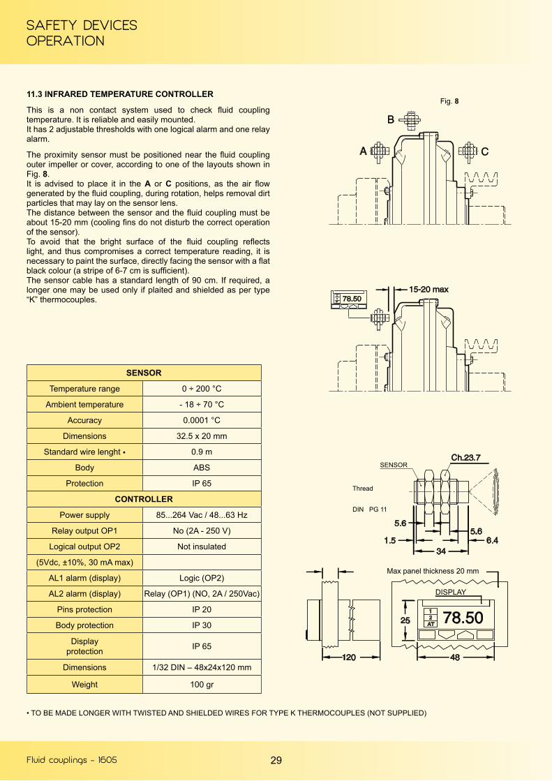
11.3 INFRARED TEMPERATURE CONTROLLER
This is a non contact system used to check fluid coupling temperature. It is reliable and easily mounted.It has 2 adjustable thresholds with one logical alarm and one relay alarm.
The proximity sensor must be positioned near the fluid coupling outer impeller or cover, according to one of the layouts shown in Fig. 8.It is advised to place it in the A or C positions, as the air flow generated by the fluid coupling, during rotation, helps removal dirt particles that may lay on the sensor lens.The distance between the sensor and the fluid coupling must be about 15-20 mm (cooling fins do not disturb the correct operation of the sensor).To avoid that the bright surface of the fluid coupling reflects light, and thus compromises a correct temperature reading, it is necessary to paint the surface, directly facing the sensor with a flat black colour (a stripe of 6-7 cm is sufficient).The sensor cable has a standard length of 90 cm. If required, a longer one may be used only if plaited and shielded as per type “K” thermocouples.
• TO BE MADE LONGER WITH TWISTED AND SHIELDED WIRES FOR TYPE K THERMOCOUPLES (NOT SUPPLIED)
Fig. 8
SENSOR
Thread
DIN PG 11
DISPLAY
Max panel thickness 20 mm
SENSOR
Temperature range 0 ÷ 200 °C
Ambient temperature - 18 ÷ 70 °C
Accuracy 0.0001 °C
Dimensions 32.5 x 20 mm
Standard wire lenght ● 0.9 m
Body ABS
Protection IP 65
CONTROLLER
Power supply 85...264 Vac / 48...63 Hz
Relay output OP1 No (2A - 250 V)
Logical output OP2 Not insulated
(5Vdc, ±10%, 30 mA max)
AL1 alarm (display) Logic (OP2)
AL2 alarm (display) Relay (OP1) (NO, 2A / 250Vac)
Pins protection IP 20
Body protection IP 30
Displayprotection IP 65
Dimensions 1/32 DIN – 48x24x120 mm
Weight 100 gr

Fluid couplings - 1605 30
OTHER TRANSFLUID PRODUCTSFOR ELECTRIC MOTOR APPLICATION
FLUID COUPLINGKSL SERIESStart up and variablespeed drive up to 4000 kW
FLEXIBLE COUPLINGBM-B3M SERIESUp to 33100 Nm
PNEUMATIC CLUTCHTP SERIESUp to 16800 Nm
FLUID COUPLINGKPT SERIESStart up and variablespeed drive up to 1700 kW
DISC & DRUM BRAKENBG/TFDS SERIESUp to 19000 Nm
ELECTRIC MACHINESPERMANENT MAGNETSSYNCHRONOUS ACUp to 100 kW

SALES NETWORK
LOCAL DISTRIBUTOR
EUROPEAUSTRIAASC GMBH4470 Enns
BELGIUM - LUXEMBURGTRANSFLUID FRANCE s.a.r.l.38110 RochetoirinPh. +33 9 75635310Fax +33 4 [email protected]
CZECH REPUBLICTESPO ENGINEERING s.r.o.602 00 Brno
DENMARK (Electric appl.)JENS S. TRANSMISSIONER A/SDK 2635 ISHØJ
ENGLAND & IRELANDMARINE AND INDUSTRIAL TRANS. LTD.Queenborough Kent me11 5ee
FINLAND (Electric appl.)OY JENS S. AB02271 Espoo
FINLAND (Diesel appl.)TRANS-AUTO AB151 48 Södertälje
FRANCETRANSFLUID FRANCE s.a.r.l.38110 RochetoirinPh. +33 9 75635310Fax +33 4 [email protected]
GERMANYTRANSFLUID GERMANY GmbHD-48529 NordhornPh. +49 5921 7288808Fax +49 5921 [email protected]
NORWAY (Diesel appl.)KGK Norge AS0664 Oslo
POLANDSENOMA LTDPL40-153 Katowice
PORTUGALREDVARIO LDA2735-469 Cacem
RUSSIA - BELARUS - KAZAKHSTANUKRAINETRANSFLUID OOO143100 MoscowPh. +7 495 7782042Mob. +7 926 [email protected]
SLOVENIAVIA INTERNATIONAL d.o.o.1241 Kamnik
SPAINTECNOTRANS BONFIGLIOLI S.A.08040 Barcelona
SWEDEN (Electric appl.)JENS S. TRANSMISSIONER ABSE-601-19 Norrkoping
SWEDEN (Diesel appl.)TRANS-AUTOSE 151-48 Sodertaly
NETHERLANDSTRANSFLUID GERMANY GmbHD-48529 NordhornPh. +49 5921 7288808Fax +49 5921 [email protected]
TURKEYREMAS81700 Tuzla Istanbul
AMERICAARGENTINAACOTEC S.A.Villa Adelina - Buenos Aires
BRAZILTRANSFLUID DO BRASIL05014-060 Sao Paulo SPPh. +55 11 48235308Fax +55 11 [email protected]
SGI PTI04461-050 Sao Paulo SP
CHILESCEM LTDASantiago Do Chile
COLUMBIAA.G.P. REPRESENTACIONES LTDA77158 Bogotà
PERU’SCEM LTDA SUC. PERULima 18
U.S.A. - CANADA - MEXICOTRANSFLUID LLCAuburn, GA30011Ph. +1 770 822 1777Fax +1 770 822 [email protected]
AFRICAALGERIA - CAMEROUN - GUINEAMAROCCO - MAURITANIASENEGAL - TUNISIATRANSFLUID FRANCE s.a.r.l.38110 Rochetoirin (France)Ph. +33 9 75635310Fax +33 4 [email protected]
EGYPTINTERN.FOR TRADING & AGENCY (ITACO)Nasr City (Cairo)
SOUTH AFRICASUB SAHARAN COUNTRIESBMG BEARING MAN GROUPJohannesburg
ASIAASIA South EastATRAN TRANSMISSION PTE LTDSingapore 608 579
CHINATRANSFLUID BEIJING TRADE CO. LTD101300 BeijingPh. +86 10 60442301-2Fax +86 10 [email protected]
INDIAPROTOS ENGINEERING CO. PRIVATE LTD600002 Tamilnadu Chennai
INDONESIAPT. HIMALAYA EVEREST JAYABarat Jakarta 11710
IRANLEBON CO.Tehran 15166
IRAN (Oil & Gas appl.)EVANPALA IncTehran 1433643115
ISRAELELRAM ENGINEERING &ADVANCED TECHNOLOGIES 1992 LTDEmek Hefer 38800
JAPANASAHI SEIKO CO. LTD.Osaka 593
KOREAKIWON CORP.Pusan - South Korea
TAIWANFAIR POWER TECHNOLOGIES CO.LTD105 Taipei
THAILANDSYSTEM CORP. LTD.Bangkok 10140
UAE - SAUDI ARABIA - KUWAIT - OMANBAHRAIN - YEMEN - QATARNICO INTERNATIONAL U.A.E.Dubai
TRANSFLUID SUBSIDIARIES
REPRESENTATIVE OFFICE
SERVICE CENTER
Global web site: www.transfluid.euE-commerce web site: www.buy-transfluid.com
TRANSFLUID S.p.A. • Via Guido Rossa, 4 • 21013 Gallarate (VA) Italy • Ph. +39 0331 28421 • Fax +39 0331 2842911 • [email protected] - 145 GB