June, Final Report for CSI RD&D Solicitation #4 Standard...
78
Final Report for CSI RD&D Solicitation #4, Standard Communication Interface and Certification Test Program for Smart Inverters ii June, 2016 Final Report for CSI RD&D Solicitation #4 Standard Communication Interface and Certification Test Program for Smart Inverters Brian Seal, Electric Power Research Institute Tom Tansy, Bob Fox, Anil Pochiraju, SunSpec Alliance Jay Johnson, Jordan Henry, Sandia National Laboratories Frances Cleveland, Xanthus Consulting International William Colavecchio, Timothy P. Zgonena, Underwriters Laboratories Sebastian Hassell, Brian Lydic, Fronius Gordon Lum, Kitu Systems Jon Sharp, Christian Tschendel, Elliot Smith, SMA TJ Vargas, Denver Hinds, SMUD Josh McDonald, Steven Robles, SCE
-
Upload
duongtuyen -
Category
Documents
-
view
220 -
download
0
Transcript of June, Final Report for CSI RD&D Solicitation #4 Standard...

Final Report for CSI RD&D Solicitation #4, Standard Communication Interface and Certification Test Program for Smart Inverters ii
June, 2016
Final Report for CSI RD&D Solicitation #4
Standard Communication Interface and
Certification Test Program for Smart Inverters
Brian Seal, Electric Power Research Institute Tom Tansy, Bob Fox, Anil Pochiraju, SunSpec Alliance Jay Johnson, Jordan Henry, Sandia National Laboratories Frances Cleveland, Xanthus Consulting International William Colavecchio, Timothy P. Zgonena, Underwriters Laboratories Sebastian Hassell, Brian Lydic, Fronius Gordon Lum, Kitu Systems Jon Sharp, Christian Tschendel, Elliot Smith, SMA TJ Vargas, Denver Hinds, SMUD Josh McDonald, Steven Robles, SCE

Final Report for CSI RD&D Solicitation #4, Standard Communication Interface and Certification Test Program for Smart Inverters ii
Final Report for CSI RD&D Solicitation #4 Standard Communication Interface and Certification Test Program for Smart Inverters Brian Seal, Tom Tansy, Bob Fox, Anil Pochiraju, Jay Johnson, Jordan Henry, Frances Cleveland, William Colavecchio, Timothy P. Zgonena, Sebastian Hassell, Brian Lydic, Jon Sharp, Christian Tschendel, Elliot Smith, TJ Vargas, Denver Hinds, Josh McDonald, Steven Robles, Gordon Lum
Abstract This document is the final report of a two year development and demonstration program under the California Solar Initiative (CSI) RD&D Solicitation #4, entitled “Standard Communication Interface and Certification Test Program for Smart Inverters”. The project was carried out between June 2014 and June 2016 by a diverse project team including key stakeholders in the area of grid‐supportive smart solar inverters. The motivation for the project, and its functional scope, were driven by the revision of California Rule 21 which was ongoing during the project. Rule 21 establishes the requirements for distributed energy resource (DER) interconnection in California.
On a broader stage, the Institute of Electrical and Electronic Engineers (IEEE) was actively revising the P1547 standard which has served as the basis for grid codes throughout North America. This revision is similar to those in California and in this sense this project relates‐to and accelerates industry activities beyond California.
The central focus of the project was communication interoperability based on open standards. Specifically, the project sought to assess the potential for solar inverter manufacturers to mass‐produce and certify products that could work in any communication system by way of a standard modular communication interface. Likewise, the project sought to assess the potential for communication system providers to develop standard modems/modules that connect seamlessly to any solar inverter without customization or modification.
The value of achieving such interoperability cannot be overstated. Studies by EPRI and others have shown that smart inverter functions can double the amount of solar PV that can be hosted on a typical distribution system. Further studies have shown that it is difficult to identify particular settings that can be used universally and have positive benefit at all times and all locations. In fact,

Final Report for CSI RD&D Solicitation #4, Standard Communication Interface and Certification Test Program for Smart Inverters ii
smart functions can work against the grid, making conditions worse in many cases. To achieve maximum potential to deploy distributed energy resources (DER), communication systems will be needed. And in order for such communication system to be feasible, standard communication interfaces will be needed. This is the specific issue that this project aimed to address.
To enable the interoperability assessments, members of the project team independently developed two types/brands of residential smart inverters and two types/brands of communication systems. This resulted in four combinations (2x2) that could be tested.
Testing was first performed in a certification and compliance environment, involving just the smart inverters. This was followed by end‐to‐end integration testing of the communication systems and inverters in laboratory environments and then finally with field testing of the same equipment so that exposure to real world conditions is gained.
This project resulted in a number of detailed reports that preceded this final report. These are available on the CSI website at: http://www.calsolarresearch.ca.gov/funded‐projects/107‐sol‐4‐standard‐communication‐interface. This report summarizes those detailed accounts to provide a more concise summary of the work performed and conclusions of the project.

Final Report for CSI RD&D Solicitation #4, Standard Communication Interface and Certification Test Program for Smart Inverters ii
Table of Contents
1 INTRODUCTION ........................................................................................................................... 8
1.1 Assessing Interoperability ................................................................................................... 3 1.2 Certification and Compliance Framework for Smart Inverters .......................................... 4
2 PROJECT CONTEXT AND FUNCTIONAL SCOPE ............................................................................ 6
2.1 Functional Scope ................................................................................................................. 7
3 DEVELOPMENT OF COMPLIANCE TEST PROCEDURES ................................................................ 9
3.1 Advanced Inverter Functions Included in Protocols ........................................................... 9 3.2 Protocol Contents ............................................................................................................. 10
4 DEVELOPMENT OF OPEN PROTOCOL AND TEST SOFTWARE ................................................... 11
4.1 CA Rule 21 Phase 1 Communication Interface Definition ................................................ 11 4.2 “C” Driver Software for Gateway Development ............................................................... 12 4.3 Test Framework Software ................................................................................................. 12
5 COMPLIANCE TESTING .............................................................................................................. 14
5.1 UL1741 SA Evaluation Requirements ............................................................................... 14 5.2 UL Inverter Testing ............................................................................................................ 15
Inverters ................................................................................................................ 15 UL Test Equipment ................................................................................................ 16 Communications Software Interface .................................................................... 17 Compliance Testing Results .................................................................................. 18 Conclusions from Compliance Testing .................................................................. 21
6 SMART INVERTER DEVELOPMENT ............................................................................................ 22
6.1 Fronius .............................................................................................................................. 22 6.2 SMA ................................................................................................................................... 23
7 COMMUNICATION SYSTEM DEVELOPMENT ............................................................................ 25
7.1 IEEE 2030.5 System ........................................................................................................... 25 Kitu/AutoGrid Test Configuration ......................................................................... 25 QualityLogic Server Test Configuration ................................................................ 25 Kitu Gateway ......................................................................................................... 26 Kitu CTA‐2045 Module .......................................................................................... 26 Autogrid 2030.5 DER Server ................................................................................. 27

Final Report for CSI RD&D Solicitation #4, Standard Communication Interface and Certification Test Program for Smart Inverters ii
Quality Logic 2030.5 Test Harness ........................................................................ 27
7.2 OpenADR 2.0b System ...................................................................................................... 27 OpenADR 2.0b Adaptation to Support Smart Inverters ....................................... 29 OpenADR 2.0b Smart Inverter Technical Approach ............................................. 29
8 LABORATORY TESTING .............................................................................................................. 33
8.1 Southern California Edison Laboratory Testing ................................................................ 33 8.2 Sacramento Municipal Utility District Laboratory Testing ............................................... 41
Test Environments and Configuration .................................................................. 41 Utility DER Head End System ................................................................................ 43 SunSpec based Inverters ....................................................................................... 44 CEA‐2045 Module(s) ............................................................................................. 44 Local Area Network Router ................................................................................... 45 Modbus Browsing Software and Hardware .......................................................... 45 Electrical Setup...................................................................................................... 46 Summary of SMUD’s Test Observations ............................................................... 46
8.3 EPRI Supplemental Laboratory Testing ............................................................................. 52
9 FIELD TESTING ........................................................................................................................... 67
9.1 Southern California Edison Field Testing .......................................................................... 67 9.2 Sacramento Municipal Utility District Field Testing ......................................................... 67
10 CONCLUSIONS ........................................................................................................................... 68
10.1 Positive Outcomes ............................................................................................................ 68 10.2 Challenges ......................................................................................................................... 69

Final Report for CSI RD&D Solicitation #4, Standard Communication Interface and Certification Test Program for Smart Inverters ii
List of Figures Figure 1‐1, Overall Project Process and Deliverables ..................................................................... 2 Figure 1‐2, Interoperability Assessment in a Two‐by‐Two Fashion ................................................ 4 Figure 2‐1, This Project in the Context of Related Industry Activities ............................................ 6 Figure 6‐1, Example of Direct Communication Module Placement ............................................. 22 Figure 6‐2, Fronius IG Plus Advanced Inverter with Standard Communication Interface ........... 23 Figure 6‐3, SMA Sunny Boy Advanced Inverter with Standard Communication Interface .......... 24 Figure 7‐1, OpenADR 2.0b Communication System ..................................................................... 28 Figure 7‐2, EPRI OpenADR 2.0b Module ....................................................................................... 29 Figure 7‐3, Example Volt‐VAR curve ............................................................................................. 30 Figure 7‐4, Limit maximum real power ......................................................................................... 31 Figure 8‐1, Communication Architecture used in SCE Labs .......................................................... 34 Figure 8‐2, Diagram of Electrical Test Setup in SCE Labs .............................................................. 35 Figure 8‐3, SCE DER Laboratory Setup – Inverters and Communication Modules ....................... 35 Figure 8‐4, SCE DER Laboratory Setup – Power Supplies and Loads ............................................ 36 Figure 8‐5, Sample Volt‐VAR Under‐Voltage Test ........................................................................ 38 Figure 8‐6, Sample Voltage‐Watt Test with the Fronius Inverter ................................................. 40 Figure 8‐7, SMUD Laboratory Testing Setup ................................................................................ 43 Figure 8‐8 EPRI’s’ laboratory setup. .............................................................................................. 52 Figure 8‐9, Volt‐Var Function, Reactive Power vs.AC Voltage for SMA ........................................ 54 Figure 8‐10 Volt‐Var Function, Reactive Power vs.AC Voltage for Fronius .................................. 55 Figure 8‐11 Power Factor Test Results for Fronius ....................................................................... 56 Figure 8‐12 VAR Preference with Fixed Power Factor Function for Fronius ................................ 57 Figure 8‐13 Maximum Power Limit Function Real Power vs. Power Limit Setting for Fronius .... 58 Figure 8‐14 Volt‐Watt Function, Real Power vs. AC Voltage for SMA .......................................... 59 Figure 8‐15 Volt‐Watt Function, Real Power vs. AC Voltage for Fronius ..................................... 61 Figure 8‐16 Frequency‐Watt Function, Real Power vs. AC Voltage for Fronius ........................... 61 Figure 8‐17, Voltage Measurement Comparison for SMA ........................................................... 63 Figure 8‐18, Status monitoring points supported by the SMA Inverter ....................................... 64 Figure 8‐19, Voltage Measurement Comparison for Fronius ....................................................... 64 Figure 8‐20, Status monitoring points supported by the Fronius. Snapshot of the SunSpec Dashboard. .................................................................................................................................... 65 Figure 10‐1, GridWise Architecture Council’s Eight‐Layer Interoperability Model ...................... 70

Final Report for CSI RD&D Solicitation #4, Standard Communication Interface and Certification Test Program for Smart Inverters ii
List of Tables Table 1‐1, Project Deliverables ....................................................................................................... 2 Table 2‐1, Functional Scope Matrix ................................................................................................ 8 Table 3‐1: Phase 1 and Select Phase 2 and 3 Advanced DER Functions in the Test Protocols. ... 10 Table 8‐1, SCE Laboratory Test Results Summary ........................................................................ 36 Table 8‐2, Volt‐VAR Communication Results Summary ............................................................... 37 Table 8‐3, Fixed Power Factor Communication Results Summary ............................................... 38 Table 8‐4, Fixed Power Factor Functionality Results Summary .................................................... 38 Table 8‐5, Limit Maximum Power Communication Results Summary ......................................... 39 Table 8‐6, Limit Maximum Power Functionality Results Summary .............................................. 39 Table 8‐7, Volt‐Watt Communication Results Summary .............................................................. 39 Table 8‐8, Frequency‐Watt Communication Results Summary.................................................... 40 Table 8‐9, Connect‐Disconnect Communication Results Summary ............................................. 41 Table 8‐10, Connect‐Disconnect Functionality Results Summary ................................................ 41 Table 8‐11, Monitoring Communication Results Summary .......................................................... 41 Table 8‐12, Model Software Version for the Inverters Tested ..................................................... 53 Table 8‐13, Summarized Test Results from EPRI’s Supplemental Testing ................................... 53 Table 8‐14, Summary of Monitoring Test Results for SunSpec Dashboard and VTN ................... 63

Final Report for CSI RD&D Solicitation #4, Standard Communication Interface and Certification Test Program for Smart Inverters ii
1 INTRODUCTION
This project created next‐generation solar inverters, tested their functionality, assessed interoperability, and developed a certification and compliance framework. The value of this activity is based on the proposition that the grid can accommodate more distributed renewable energy if the devices can be successfully connected in communication networks. The approach taken applied open standards, recognizing that to practically achieve connectivity in an environment of diverse brands and types of equipment, standard communication interfaces will be required. The primary steps involved in the project are identified in flowchart of Figure 1‐1, and described throughout this report. The project was carried out concurrently with the California Rule 21 revision process and development of the UL 1741 SA and sought to support and accelerate those developments. California Rule 21 establishes the requirements for distributed energy resource (DER) interconnection in California and UL1741 is a compliance test specification for DER that is used for certification.

Final Report for CSI RD&D Solicitation #4, Standard Communication Interface and Certification Test Program for Smart Inverters ii
Figure 1‐1, Overall Project Process and Deliverables
The numbered circles in Figure 1‐1 indicate resulting materials and artifacts of the project, as listed in Table 1-1.
Table 1‐1, Project Deliverables
Deliverable Number
Title Description
1 Standard Communication Interface and
Certification Test Program for Smart Inverters One‐page summary
2 Applying SunSpec Modbus to Meet California
Rule 21 Requirements Technical/Protocol
Document
3 OpenADR Mapping for Grid Control Enabled
Inverters Technical/Protocol
Document
4 SEP 2.0 Mapping for Grid Control Enabled
Inverters Technical/Protocol
Document
5 Suggested Additions to the CEA‐2045 Standard Technical/Protocol
Document

Final Report for CSI RD&D Solicitation #4, Standard Communication Interface and Certification Test Program for Smart Inverters ii
6 Provisional Electric Rule 21 Test Protocols for
Advanced Inverter Functions Test procedure for inverter
functional evaluation
7 Cyber Security Requirements and
Recommendations Recommendations/Guide for
future systems
8 Open Source SunSpec Driver Code Software
9 SunSpec Test Software Software
10 Fronius Advanced Inverter Product – Hardware and
Firmware
11 SMA Advanced Inverter Product – Hardware and
Firmware
12 Kitu Systems IEEE 2030.5 Communication
System and Modules Product – Hardware and
Firmware
13 EPRI OpenADR Communication System and
Modules Product – Hardware and
Firmware
14 Compliance Test Report for Two Inverters Compliance Test Results
15 Laboratory Integration Test Plan Test Plan
16 Laboratory Test Results Test Results
17 Filed Test Plan Test Plan
18 Field Test Results Test Results
19 Final Report This Document
20 Final Webcast Slides PowerPoint Slides
1.1 Assessing Interoperability
The primary purpose this project was to assess the ability for residential solar inverters to be designed with an open standard communication interface enabling them to connect and work in any communication system. Such capability is needed in order to maximize the amount of renewable energy that can be connected to the grid. The wide range of types, brands, and scales of solar photovoltaic systems make it impractical to create cohesive grid‐supporting systems without a common communication interface to the devices. The approach used for this project utilized the SunSpec Modbus protocol and the Consumer Electronics Association’s CEA‐2045 modular port interface. This approach was interesting, particularly for small‐scale residential inverters, for four primary reasons:
1. It has the potential to reduce product cost upfront, avoiding the integration of communication technologies that might not be needed into an increasingly cost‐sensitive class of product.
2. It could enable mass production and communication diversity – allowing a single inverter design to be mass produced and widely distributed because it is compatible with all kinds of communication systems.

Final Report for CSI RD&D Solicitation #4, Standard Communication Interface and Certification Test Program for Smart Inverters ii
3. It could avoid communication obsolescence, enabling communication systems to evolve over the long service life of the inverter through easily replaceable modem/modules.
4. It could enable certification and compliance testing to be streamlined and better automated by making a common test harness possible.
In order to perform the assessment, the project developed a two‐by‐two test environment as illustrated in Figure 1‐2. Two residential inverter companies, project partners Fronius and SMA, independently developed inverters with grid‐supportive functionality and the SunSpec‐based port interface. Two communication systems were also developed, one by Kitu Systems based on the IEEE 2030.5 protocol and one by EPRI based on the OpenADR 2.0b protocol. Both systems included head‐end software and local modem/modules that plugged‐in to the inverters. In both cases, the local connection to the inverter was the same, based on the SunSpec protocol, with the modem/modules providing translation to/from their native system protocols and cyber security as needed.
Figure 1‐2, Interoperability Assessment in a Two‐by‐Two Fashion
1.2 Certification and Compliance Framework for Smart Inverters
The project also focused on developing a ready certification and compliance test framework that includes the functional and communication aspects of smart inverters. Regardless of how well they are written, paper standards alone are not sufficient to achieve product interoperability because even small differences in implementation can result in failure of information and communication systems to work together.

Final Report for CSI RD&D Solicitation #4, Standard Communication Interface and Certification Test Program for Smart Inverters ii
The end‐goal of establishing a comprehensive certification framework is to ensure that devices that are fielded today can be practically and economically integrated into smart‐home, aggregator, and advanced distribution management systems in the future. Inverters and solar installations are long‐life systems and as levels continue to rise, the need to intelligently connect will be heightened. To address this goal, project partner Sandia National Laboratories developed a comprehensive test procedure for smart inverters. These procedures sought to balance the completeness of testing with the time and cost of test execution. Many smart inverter functions are continuously adjustable, so the question of how many levels/values to configure and test is difficult. For example, if a smart inverter supports volt‐var control using a curve configuration, how many curves, of how many points, and of what curve shapes must be tested to become confident that the product works properly? In addition, many smart inverter functions can be simultaneously active, resulting in an essentially infinite number of combinations of inverter settings. The test procedure developed by Sandia National Laboratories, entitled “Provisional Electric Rule 21 Test Protocols for Advanced Inverter Functions” has been published1 and is publicly available. This procedure was provided to project partner Underwriters Laboratories and used to accelerate the development of the UL1741 SA – a certification procedure aligned with the California Rule 21 revisions. It is important to note that the official UL1741 SA certification process does not require a particular or standard communication protocol because the approved Phase 1 CA Rule 21 revisions did not require communications. In this regard, the compliance testing performed in this project is different than the UL1741 SA. The functional scopes are aligned, but the certification framework in this project also required strict adherence to the SunSpec/CEA‐2045 communication interface specifications. If a function existed in an inverter, but could not be accessed (monitored and managed) via the standard communication protocol, then it was considered to be non‐compliant because it would not be accessible/useable in the field. As indicated by the dashed lines in Figure 1‐2, UL testing was performed using the local ports at the inverters. The SunSpec Alliance developed and provided to UL a test software and protocol to support this testing.
1 http://www.calsolarresearch.ca.gov/funded‐projects/107‐sol‐4‐standard‐communication‐interface

Final Report for CSI RD&D Solicitation #4, Standard Communication Interface and Certification Test Program for Smart Inverters ii
2 PROJECT CONTEXT AND FUNCTIONAL SCOPE
This project was carried out during a time of high industry activity in the area of smart inverter integration. The annotated timeline in Figure 2‐1 identifies key activities to which this project related.
Figure 2‐1, This Project in the Context of Related Industry Activities
Global efforts to define common smart inverter functions began in 2008 and resulted in the IEC 61850‐7‐420 and61850‐7‐520 standards. These provide text descriptions of common grid‐supportive functions and a reference information model that can be mapped into other communication protocols. EPRI also published a description of these common functions that is publicly available2. These common grid‐supportive functions have been mapped SunSpec Modbus, IEEE 2030.5 and OpenADR 2.0b as used in this project. Grid codes are being developed that require DER to have certain grid‐supportive functionality in order to be deployed and grid‐tied. In the state of California, the grid‐codes are based on Rule 21, which has been undergoing revision as indicated in Figure 2‐1. This revision process was supported by an open focus group called the Smart Inverter Working Group (SIWG) led by
2 Common Functions for Smart Inverters, Version 3. EPRI, Palo Alto, CA: 2013. 3002002233

Final Report for CSI RD&D Solicitation #4, Standard Communication Interface and Certification Test Program for Smart Inverters ii
project partner Xanthus Consulting. The SIWG’s work was performed in phases, the first of which was approved by the state of California during this project. A primary focus of the SIWG was selecting the functionalities that DER must support in order to be deployed in California. This selection was done through a stakeholder engagement process and built upon the IEC 61850‐7‐420 common functions. As a result of the SIWG process, a set of requests was submitted to the International Electrotechnical Commission (IEC) to improve the IEC 61850‐7‐420 and IEC 61850‐7‐520 specifications. This request was accepted and, as a result, revision of these specifications is presently underway.
2.1 Functional Scope
The present project aimed to use the California Rule 21 revisions to establish the functional scope. Although the SIWG process remained in process during the project, the team did what was possible to track the work in process and to adhere as closely as possible to the latest definition. This included awareness of the advanced functionalities considered during Phase 3. Table 2‐1 provides a summary of the functional scope for the project. The left‐hand column identifies the most significant functions and features of smart inverters relative to the CA Rule 21 process as of the beginning of the project. The headings in the top row identify the key steps of the project, and the marks in the matrix indicate whether or not each function was covered in that step:
To be Included in Sandia Test Procedures
To be Included in the Communication Interface Specification Document
To be Supported by the SunSpec Modbus Reference Code
To be Supported by SMA Sunny Boy
To be Supported by Fronius IG Plus
To be Tested in the UL Test System
To be Operational, but in a fixed fashion, During Utility Testing
To be Managed/Exercised by the Utility Communication Systems This matrix was developed early in the project, a reflection of the team’s estimates of what would be possible. The scope was then constrained as the project progressed as standards developments evolved and manufacturer limitations were identified in R&D.

Final Report for CSI RD&D Solicitation #4, Standard Communication Interface and Certification Test Program for Smart Inverters ii
Table 2‐1, Functional Scope Matrix
Function or
Communication
Verification
Definition of this Function within the context of
this project.
To be
Included in San
dia Test
Procedures
To be Included
in the Com
m Interfa
ce
Specification
Docum
ent
To be Suppo
rted by th
e SunSpec
Modbus R
eference Code
To be Supported b
y SMA Sunny B
oy
To be Supported
by Fronius IG
Plus
To be Tested
in the UL Test System
To be Active in
the Inverter D
uring
SMUD Field
Testing (fixed)
To be
Exercised by the SM
UD
Com
munication
Systems (lab and field
To be Active in
the Inverter D
uring SC
E
Field Testing
(fixed)
To be Exe
rcised by the SCE
Com
munication
Systems (lab and field
Anti‐Islanding Protection Non‐configurable. A built‐in function of the inverter. N/A N/A N/A N/A
Low/High Voltage Ride‐
Through
Non‐configurable. A built‐in function of the inverter.
Set to the levels identified in the CA Rule 21
recommndations. Able to pass the test as described in
the Sandia test procedure.
Low/High Frequency Ride‐
Through
Non‐configurable. A built‐in function of the inverter.
Set to the levels identified in the CA Rule 21
recommndations. Able to pass the test as described in
the Sandia test procedure.
Volt‐Var Function with
Watt‐Priority
Implemented as a variably‐adjustable function. Able
to accept and act on an array of X‐Y points sent per the
Sunspec standard. Able to handle curves with up to 6
points. It is acceptable for this project to NOT support
hysteresis curves. The "Time Window" and "Ramp
Time" variables that are part of these functions must
be supported.
N/A N/A
Ramp Rates and Soft Start
This refers to the ramp limit that is called out in CA
Rule 21 and separate from those associated with
control actions (see description of the volt‐var
function for example). Specifically, this refers to a
ramp‐time limit in response to rising PV output
(positive limit)
Power Factor Function To be continuously adjustable from unity to .9[PF] N/A N/A
Monitor DER Status N/A N/A
Limit Maximum Real
Power Function
To be continuously adjustable from full power (100%)
to the shutdowwn level (e.g. 10%) of the inverter. N/A N/A
Connect/Disconnect
Function
A simple boolean function. Cease to energize at the
ECP. N/A Lab N/A Lab
Frequency‐Watt Function Same expectations as for Volt‐Var function. TBD TBD TBD TBD
Voltage‐Watt Function Same expectations as for Volt‐Var function. N/A TBD N/A Dynamic Reactive Current
Support N/A N/A
SMUD SCE

Final Report for CSI RD&D Solicitation #4, Standard Communication Interface and Certification Test Program for Smart Inverters ii
3 DEVELOPMENT OF COMPLIANCE TEST PROCEDURES
As part of this project, Sandia National Laboratories (Sandia), EPRI, Xanthus Consulting, Underwriters Laboratories, SunSpec Alliance, Loggerware, utilities, and PV inverter manufacturers drafted a certification protocol for advanced inverter and interoperability functions proposed by the Rule 21 SIWG. This effort was completed in collaboration with the UL 17413 Standards Technical Panel (STP) because they were concurrently drafting the UL 1741 Supplement A certification protocol to test advanced DER functionality. In fact, this project accelerated the development of many of the UL 1741 SA test procedures by drafting, refining, and compiling the test procedures in a single document.
The final report4 consists of test protocols to evaluate the electrical performance and interoperability of DER inverters defined in the CA Rule 21 SIWG Phase 1 proposal and select functions from Phase 2 and Phase 3. Many of these functions are similar to those defined by the International Electrotechnical Commission (IEC) Technical Report (TR) 61850‐90‐7, so previous work5‐6 in designing testing protocols for those functions was heavily leveraged.
3.1 Advanced Inverter Functions Included in Protocols
The final report was structured with separate appendices for each of the Rule 21 advanced inverter functions. The functions included in this document are displayed in Table 3‐1, however the Rule 21 Phase 2 and Phase 3 functions are not defined fully by the SIWG or the IOUs at the time of this project, so those certification protocols must be updated based on future SIWG discussions surrounding these functions. Abbreviations for the protocols are labeled R21‐x‐y, where x is the phase and y is the function designator; for instance, R21‐1‐AI is Anti‐islanding Protection in Rule 21 Phase 1. The function designator is matched to IEC TR 61850‐90‐7 nomenclature when there is a synonymous function, e.g., L/HVRT, INV3, VV11, and DS93.
3 Underwriters Laboratories 1741 Ed. 2, "Inverters, Converters, Controllers and Interconnection System Equipment for use with Distributed Energy Resources," 2010. 4 J. Johnson, S. Gonzalez, T. Zgonena, M. McGirr, J. Hopkins, B. Seal, F. Cleveland, T. Tansy, and B. Fox, “Draft Electric Rule 21 Test Protocols for Advanced Inverter Functions,” California Solar Initiative report for California Public Utilities Commission (CPUC), Dec. 2014. 5 J. Johnson S. Gonzalez, M.E. Ralph, A. Ellis, and R. Broderick, “Test Protocols for Advanced Inverter Interoperability Functions – Main Document,” Sandia Technical Report SAND2013‐ 9880, Nov 2013. 6 J. Johnson S. Gonzalez, M.E. Ralph, A. Ellis, and R. Broderick, “Test Protocols for Advanced Inverter Interoperability Functions–Appendices,” Sandia Technical Report SAND2013‐9875, Nov 2013.

Final Report for CSI RD&D Solicitation #4, Standard Communication Interface and Certification Test Program for Smart Inverters ii
Table 3‐1: Phase 1 and Select Phase 2 and 3 Advanced DER Functions in the Test Protocols.
Appendix Function or Communication Verification Protocol Abbreviation
1 Anti‐Islanding Protection (AI) R21‐1‐AI
2 Low/High Voltage Ride‐through (L/HVRT) and Low/High Frequency Ride‐through (L/HFRT)
R21‐1‐L/HVRT R21‐1‐L/HFRT
3 Normal Ramp Rate and Soft‐Start Ramp Rate
R21‐1‐RR R21‐1‐SS
4 Fixed Power Factor and Volt‐VAR Mode with Watt‐Priority
R21‐1‐INV3 R21‐1‐VV11
5 Communication Interface R21‐2‐CI
6 Data Model R21‐2‐DATA
7 Monitor Alarms R21‐3‐A
8 Monitor DER Status and Output R21‐3‐DS93
3.2 Protocol Contents
Each of the appendices were broken into multiple sections. First, a general description of the function was provided along with the function’s purpose (grid‐support capability). This was followed by the technical specifications for certifying the DER, which included required information provided by the manufacturer, the test sequence, the test points or parameter sets, and the pass/fail criteria. For instance, the soft start ramp rate tested the equipment under test (EUT) with four different ramp rates (disabled, minimum ramp rate, average ramp rate, and maximum ramp rate), through a common test sequence. Mathematical rules for passing the test were provided in the pass/fail criteria section.
Final Report for CSI RD&D Solicitation #4, Standard Communication Interface and Certification Test Program for Smart Inverters ii
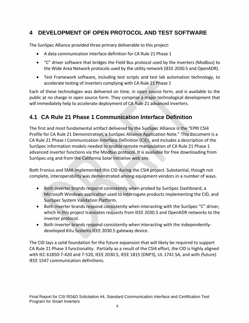
4 DEVELOPMENT OF OPEN PROTOCOL AND TEST SOFTWARE
The SunSpec Alliance provided three primary deliverable to this project:
A data communication interface definition for CA Rule 21 Phase 1
“C” driver software that bridges the Field Bus protocol used by the inverters (Modbus) to the Wide Area Network protocols used by the utility network (IEEE 2030.5 and OpenADR).
Test Framework software, including test scripts and test lab automation technology, to accelerate testing of inverters complying with CA Rule 21 Phase 1
Each of these technologies was delivered on time, in open source form, and is available to the public at no charge in open source form. They comprise a major technological development that will immediately help to accelerate deployment of CA Rule 21 advanced inverters.
4.1 CA Rule 21 Phase 1 Communication Interface Definition
The first and most fundamental artifact delivered by the SunSpec Alliance is the “EPRI CSI4 Profile for CA Rule 21 Demonstration, a SunSpec Alliance Application Note.” This document is a CA Rule 21 Phase I Communication Interface Definition (CID), and includes a description of the SunSpec information models needed to enable remote manipulation of CA Rule 21 Phase 1 advanced inverter functions via the Modbus protocol. It is available for free downloading from SunSpec.org and from the California Solar Initiative web site. Both Fronius and SMA implemented this CID during the CSI4 project. Substantial, though not complete, interoperability was demonstrated among equipment vendors in a number of ways.
Both inverter brands respond consistently when probed by SunSpec Dashboard, a Microsoft Windows application used to interrogate products implementing the CID, and SunSpec System Validation Platform.
Both inverter brands respond consistently when interacting with the SunSpec “C” driver, which in this project translates requests from IEEE 2030.5 and OpenADR networks to the inverter protocol.
Both inverter brands respond consistently when interacting with the independently‐developed Kitu Systems IEEE 2030.5 gateway device.
The CID lays a solid foundation for the future expansion that will likely be required to support CA Rule 21 Phase 3 functionality. Partially as a result of the CSI4 effort, the CID is highly aligned with IEC 61850‐7‐420 and 7‐520, IEEE 2030.5, IEEE 1815 (DNP3), UL 1741 SA, and with (future) IEEE 1547 communication definitions.
Final Report for CSI RD&D Solicitation #4, Standard Communication Interface and Certification Test Program for Smart Inverters ii
4.2 “C” Driver Software for Gateway Development
The SunSpec “C” driver is another important deliverable of the CSI4 project. The “C” driver is based on and CA Rule 21 Phase 1 requirements and is designed as an open source building block for creating gateway software functionality that can be deployed on CTA‐2045 modules or other low cost, high volume industrial compute platforms. As delivered, the “C” driver software is “pre‐certified” to SunSpec standards and is known to be interoperable. The “C” language was chosen because it is broadly compatible with high‐volume and embedded computing platforms. The EPRI software development team successfully used the “C” driver to create gateway functionality to bridge IEEE 2030.5 and OpenADR protocols with the inverter protocol. IEEE 2030.5 is the “default CA Rule 21 Phase 2” protocol so validation with this system was essential. OpenADR is a likely choice for ancillary services enabled by CA Rule 21 Phase 2 so integration, once again, was serendipitous. The “C” driver open source technology can be accessed and diffused at no cost via Github.com. SunSpec supports this repository as part of its ongoing commitment to building an open source ecosystem for Distributed Energy.
4.3 Test Framework Software
Expansion of the SunSpec System Validation Platform (SunSpec SVP) and supporting test framework is another important deliverable of this project. Open source test scripts, based upon the functional test requirements developed by Sandia, are now available to support the full gamut of CA Rule 21 Phase 1 functionality plus other advanced inverter functions that will likely be considered for future CA Rule 21 phases. The capabilities of SunSpec SVP delivered during the CSI4 program remove multiple barriers to CA Rule 21 adoption including: 1) providing an open source framework that manufacturers can use to validate products in the development lab, 2) providing a template for Nationally Recognized Testing Laboratories to develop their test framework capabilities, and 3) cutting down the time needed to test advanced inverter functions from days to minutes. This last benefit—automation—is perhaps the most important because it makes the test process highly efficient and because it enables nearly unlimited variation of test scenarios and non‐stop, around‐the‐clock test sessions. Open source SunSpec SVP test scripts are also available for free download and use from Github.com.

Final Report for CSI RD&D Solicitation #4, Standard Communication Interface and Certification Test Program for Smart Inverters ii

Final Report for CSI RD&D Solicitation #4, Standard Communication Interface and Certification Test Program for Smart Inverters ii
5 COMPLIANCE TESTING
5.1 UL1741 SA Evaluation Requirements
To provide a certification path for the new CPUC Rule 21 Test Protocols for Advanced Inverter Function requirements, Industry, Utilities, National Labs, EPRI and UL worked together to develop and publish US requirements to meet this need. The outcome of this group effort is an 80 page supplement to the UL Safety Standard for Inverters, Converters, Controllers and Interconnection System Equipment for Use With Distributed Energy Resources, UL1741. This supplement A is designated as UL1741 SA which includes the test requirements, test methods and pass fail criteria needed to evaluate grid support/advanced utility interactive inverters for compliance with various source requirements documents (SRDs) including but not limited to CPUS Rule 21. A Grid Support Utility Interactive certification under the UL1741SA standard (once published) will be necessary to address the certification needs defined by utility engineers under local grid codes as well as electrical inspectors for compliance with the NEC within the US.
The 1741 SA requirements are in addition to the other applicable requirements within the UL1741 standard. UL1741 SA defines the evaluation criteria for utility interactive inverters with grid support functions that are rated and specified as “Grid Support Utility Interactive Inverters”.
This new “Grid Support Utility Interactive” nomenclature is intended to differentiate these products from the traditional “utility interactive inverters” evaluated to the existing IEEE 1547 and IEEE 1547.1 (excluding the amendments). Those older utility interactive inverters have considerably less functionality built around basic voltage and frequency trip limits.
UL1741 SA is intended to be an interim solution to bridge the gap until IEEE 1547 and IEEE 1547.1 are revised to include the new grid support / advanced inverter requirements. The UL1741 SA was provided by UL to the IEEE 1547.1 committee as a seed document to speed the development of the IEEE 1547.1 standard.
The scope of UL1741 SA was intentionally limited to speed its development and address the needs of the first phase of the CPUC Rule 21, that only includes autonomous grid support / advanced inverter functionality. With this in mind the UL1741 SA does not include communications requirements related to grid support/advanced inverter functionality which are coming in the next phases of the Rule 21 requirements. As such the critical communication element of this CSI4 project was not addressed in the draft of UL1741 SA.
The testing performed by UL under this CSI4 project was focused to validate the SMA and Fronius inverters with Grid Support Utility Interactive Inverter Functionality. The compliance criteria for this project was based up on the grid support / advanced functionality performance including communications through the CEA/CTA2045 interface device using the SunSpec software program.
As of the publication of this report, the UL1741 SA draft is in still in its ballot period. The initial ballot results were very positive and met the ANSI requirements for consensus although the draft received 224 ballot comments / proposed revisions. The 1741 SA task group has taken on an aggressive meeting schedule to resolve these comments in 3 weeks’ time to maintain the intended

Final Report for CSI RD&D Solicitation #4, Standard Communication Interface and Certification Test Program for Smart Inverters ii
publication by the end of August 2016. Publication of the UL1741 SA will start the new Rule 21 Grid Support / Advanced inverter compliance clock that will require new grid tied inverters to be compliant with and Listed to the UL1741 SA requirements.
5.2 UL Inverter Testing
Inverters
Under this project UL tested two different manufacturers’ inverters with grid support / advanced functionality. Each inverter was tested as an assembly including a CEA/CTA 2045 communications interface.
Manufacturer Model Serial number Firmware Version
SMA SB 5000TL‐22‐US 1913124411 02.63.33.S
Fronius IG Plus V 3.8‐1 22240387 HW: 6.2.28
Communication: 2.1.21
Figure 5.1 Inverters
Model Pictures
CEA 2045 AC to Ethernet (was used with SMA
Inverter)
CTA 2045 AC to RS‐485
(was used with Fronius Inverter)
CEA‐2045 USB UCM AC Test Cable V1.0
(was used with Fronius and SMA Inverter)
The linked imag

Final Report for CSI RD&D Solicitation #4, Standard Communication Interface and Certification Test Program for Smart Inverters ii
Figure 5.2 CEA/CTA 2045 Communications Interface
UL Test Equipment
The Inverters (EUTs) were connected to a Grid simulator (programmable AC‐power supply) and a PV‐Simulator (DC‐power‐supply). The scope (Highspeed‐Data‐Acquisition system) was used for measurement of the AC‐voltages and currents. The Power‐Analyzer was used for measurements of the AC voltages, currents, power‐factor, active power, reactive power, apparent power and the DC‐voltages and currents. The inverter and CEA 2045 communications device were tested as an assembly which was connected to a computer to control and read‐out parameters.
Figure 5.3 UL Test Configuration

Final Report for CSI RD&D Solicitation #4, Standard Communication Interface and Certification Test Program for Smart Inverters ii
Figure 5.4: UL Inverter Test Lab
Equipment Manufacturer Model
Grid simulator Ametek / California Instruments MX‐45
PV Simulator Magna Power MT 100‐1000
Scope Yokogawa SL1000
Power analyzer Yokogawa WT1800
Figure 5.5: Test equipment
Communications Software Interface
The communications with the inverters was performed through two SunSpec software interfaces. The SunSpec software was primary basis for communication with the EUT and compliance was judged based up on the ability of the EUT to receive and implement the commands via SunSpec software. SunSpec SVP provides an environment that can manage and execute test scripts that utilize libraries that provide access to all the necessary components in the system. The SunSpec SVP Software was used to perform tests automatically where possible.
The SunSpec Dashboard is an application that enables interrogation and inspection of devices and documents using SunSpec technology. UL Test Software An existing UL automated testing environment/system was also used to interact with the different devices and automate test‐procedures.

Final Report for CSI RD&D Solicitation #4, Standard Communication Interface and Certification Test Program for Smart Inverters ii
Compliance Testing Results
At the time this project was performed, the two inverters that were tested did not include all of the advanced grid support functions that were evaluated under this project. Those functions that were not implemented were not able to be tested. During the project SMA provided new firmware that included increased functionality and aided in testing. The final test results reflect the available inverter functionality with the firmware version listed in the table above.
Advanced Inverter Test Functional Test Results Performed through SunSpec Software via the CEA 2045 Communications Interface
Fronius SMA
UL 1741 SA9 L/HVRT
Not implemented in SunSpecmodel
Not implemented in SunSpec model
UL 1741 SA10 L/HFRT
Not implemented in SunSpecmodel
Not implemented in SunSpec model
UL 1741 SA11 RR‐ Normal Ramp
Not implemented in SunSpecmodel
Yes
UL 1741 SA11 Soft Start Ramp
Not implemented in SunSpecmodel
Yes
UL 1741 SA12 INV3 Fixed Power Factor
Yes No, did not work with SunSpec
software
UL 1741 SA13 VV11 Volt/Var Mode
Yes Yes
UL 1741 SA17 Optional: Frequency‐Watt
Not implemented in SunSpecmodel
Not tested due to unrelated inverter sample failure.
UL 1741 SA18 Optional: Volt‐Watt
Yes Yes
Figure 5.6: Test Communication Capability via SunSpec Software and CEA/CTA 2045

Final Report for CSI RD&D Solicitation #4, Standard Communication Interface and Certification Test Program for Smart Inverters ii
Test SMA FRONIUS
UL 1741 SA9 L/HVRT
• Function works with SMA software.
• The function not required to work with SunSpec.
• Function works with Fronius software.
• The function not required to work with SunSpec.
UL 1741 SA10 L/HFRT
• Function works with SMA software.
• The function not required to work with SunSpec.
• Function works with Fronius software
• The function not required to work with SunSpec.
UL 1741 SA11 RR‐ Normal Ramp
Fail: Function did not work with SunSpec Software
SunSpec model includes the WGra parameter.
Parameter WGra has no effect to the ramp‐rate
Fail: Function did not work with SunSpec Software
SunSpec model did not include the WGra parameter.
UL 1741 SA11 Soft Start Ramp
Fail: Function did not work with SunSpec Software
Function not included in SunSpec software or SMA firmware.
Ramp after reconnection supported in SMA software.
Fail: Function did not work with SunSpec Software
Not included in SunSpec software.
Parameter “GPIS” startup‐speed was in the mfr menu and worked.
UL 1741 SA12 INV3 Fixed Power Factor
Fail: Function did not work with SunSpec Software
• The function works when using the SMA Software.
Pass: Function works with SunSpec Software
UL 1741 SA13 VV11 Volt/Var Mode
Pass: Function works with SunSpec Software
Pass: Function works with SunSpec Software
UL 1741 SA17 Optional: Frequency‐Watt
Unknown ‐ The function is implemented in SMA Firmware and in the SunSpec model. Due to an unrelated inverter sample failure this test could not be performed.
Fail: Function did not work with SunSpec Software
Function “GFPR” Grid frequency‐dependent power reduction is present in display‐settings and worked.

Final Report for CSI RD&D Solicitation #4, Standard Communication Interface and Certification Test Program for Smart Inverters ii
UL 1741 SA18 Optional: Volt‐Watt
Pass: A curve of 8 points is programmable.
A characteristic was set and measured
Fail: Function did not work with SunSpec Software
“GVPR” Grid Voltage‐dependent power reduction is present in display settings and curve was measured.
Inverter ‐ monitor critical components for over temp.
No observed over temperature or risk of fire hazard during testing.
No observed over temperature or risk of fire hazard during testing.
Table 5.7 Inverter Test Results

Final Report for CSI RD&D Solicitation #4, Standard Communication Interface and Certification Test Program for Smart Inverters ii
Conclusions from Compliance Testing
1. While many CA Rule 21 / UL1741 SA functions are implemented, not all were available
at the time of testing but the remaining functions are being developed.
2. Having a communications and control interface like the SunSpec (over CEA‐2045)
provides a common platform to support this testing and prevents the test lab from
having to learn and use multiple unique communication and control interfaces provided
by the individual inverter manufacturers.
3. Implementation of the communications interface is still in progress, but what is
available now greatly enhances testing automation and data collection for inverters that
use the SunSpec communications protocol. Reduction in test time speeds time to
market and reduces cost.
4. This project benefited greatly from automated test software and further development
of this automation software is necessary to match the upcoming functionality in the
UL1741SA standard slated for publication in August 2016.
5. As compared to the previous UL1741, IEEE 1547 and IEEE 1547.1 testing, this new
advanced grid support testing is orders of magnitude more complex which results in
significant increases in time and cost to implement. This new testing appears infeasible
without automation based upon the increased complexity, number of tests and
iterations per test.
6. During the testing of the advanced grid support inverter functions evaluated under this
project, neither of the inverters demonstrate characteristics that would indicate that
their safe operation was compromised.

Final Report for CSI RD&D Solicitation #4, Standard Communication Interface and Certification Test Program for Smart Inverters ii
6 SMART INVERTER DEVELOPMENT
Project partners Fronius and SMA developed the advanced inverters used in the evaluation. The project did not require the inverter manufacturers to commercialize products, and both ultimately chose to approach the development as prototype exercises. One reason for this was the lack of specific communication requirements in the approved California Rule 21 Phase 1 and ongoing process of the IEEE 1547 full revision during the timeframe of the project.
Both companies chose to use existing physical product designs, modifying firmware and adding an external communication interface as shown in Figure 6‐2 and Figure 6‐3 in order to avoid making mechanical changes to the inverter housings. This simplified the compliance testing process. Going forward, communication modules could be directly plugged inside or onto inverters such as shown in the model shown in Figure 6‐1 used in some of the project indoor/laboratory testing.
Figure 6‐1, Example of Direct Communication Module Placement
6.1 Fronius
Fronius writes this part. The two companies connect to make sure that the two sections follow the same flow and comparable content/length.

Final Report for CSI RD&D Solicitation #4, Standard Communication Interface and Certification Test Program for Smart Inverters ii
Figure 6‐2, Fronius IG Plus Advanced Inverter with Standard Communication Interface
6.2 SMA
SMA writes this part. The two companies connect to make sure that the two sections follow the same flow and comparable content/length.

Final Report for CSI RD&D Solicitation #4, Standard Communication Interface and Certification Test Program for Smart Inverters ii
Figure 6‐3, SMA Sunny Boy Advanced Inverter with Standard Communication Interface

Final Report for CSI RD&D Solicitation #4, Standard Communication Interface and Certification Test Program for Smart Inverters ii
7 COMMUNICATION SYSTEM DEVELOPMENT
7.1 IEEE 2030.5 System
IEEE 2030.5 (formerly Smart Energy Protocol 2.0 or SEP 2.0) was chosen as one of the utility communications protocols as it includes native support for DER functions and is designated by the California Smart Inverter Profile (CSIP) Rule 21 activity as the default utility interface for smart inverter communications. For the IEEE 2030.5 portion of this project, Kitu Systems Inc. provided the 2030.5 Gateway and CTA‐2045 modules for SCE and SMUD; Autogrid provided a cloud based 2030.5 DER Server for SCE; and Quality Logic provided their 2030.5 test harness for SMUD to use as a server. In addition, Kitu and Quality Logic (QL) supported Interoperability testing with the IEEE2030.5 Server and inverters. This project used two test configurations depending on whether the IEEE 2030.5 Server was on the internet or on the local HAN.
Kitu/AutoGrid Test Configuration
The SCE test configuration completed by Kitu is shown in the figure below. The Kitu Gateway connects the 2030.5 server to the CEA‐2045 module. A Wireshark Sniffer PC connected to the router WAN interface is used to sniff the Ethernet packets to/from the IEEE2030.5 Server. An RS‐485 Sniffer PC is connected to the RS‐485 interface of the inverter to sniff the Modbus commands and responses. All of the test cases were run without re‐starting the IEEE2030.5 server or the CEA‐2045 Module. Also shown is the Kitu EZ Server which is Kitu’s cloud based DER server and was used to support the testing.
QualityLogic Server Test Configuration
The QL server runs on a Windows PC. The test configuration for the QL server is shown in the figure below. A standard Wi‐Fi Access Point is used to connect the QL server to the Kitu CEA‐2045 module. The QL Server PC also runs Wireshark to sniff the Ethernet packets to/from the IEEE2030.5 Server. An RS‐485 Sniffer PC is connected to the RS‐485 interface of the inverter to sniff the Modbus commands and responses. Both the QL server and the CEA‐2045 Module were restarted prior to each test because the QL server does not allow changing DER Control parameters without stopping and restarting the server.
Final Report for CSI RD&D Solicitation #4, Standard Communication Interface and Certification Test Program for Smart Inverters ii
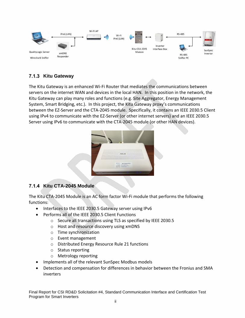
Kitu Gateway
The Kitu Gateway is an enhanced Wi‐Fi Router that mediates the communications between servers on the internet WAN and devices in the local HAN. In this position in the network, the Kitu Gateway can play many roles and functions (e.g. Site Aggregator, Energy Management System, Smart Bridging, etc.). In this project, the Kitu Gateway proxy’s communications between the EZ‐Server and the CTA‐2045 module. Specifically, it contains an IEEE 2030.5 Client using IPv4 to communicate with the EZ‐Server (or other internet servers) and an IEEE 2030.5 Server using IPv6 to communicate with the CTA‐2045 module (or other HAN devices).
Kitu CTA-2045 Module
The Kitu CTA‐2045 Module is an AC form factor Wi‐Fi module that performs the following functions:
Interfaces to the IEEE 2030.5 Gateway server using IPv6
Performs all of the IEEE 2030.5 Client Functions o Secure all transactions using TLS as specified by IEEE 2030.5 o Host and resource discovery using xmDNS o Time synchronization o Event management o Distributed Energy Resource Rule 21 functions o Status reporting o Metrology reporting
Implements all of the relevant SunSpec Modbus models
Detection and compensation for differences in behavior between the Fronius and SMA inverters

Final Report for CSI RD&D Solicitation #4, Standard Communication Interface and Certification Test Program for Smart Inverters ii
Autogrid 2030.5 DER Server
AutoGrid’s Cloud‐based 2030.5 server was used by SCE for the end‐to‐end lab and field testing The server contains utility‐defined DER programs, each of which has a default DER Control setting. The server allows operators to create DER programs, define the default DER Control for a program, and assign DER devices to specific DER programs. These program assignments are managed through the 2030.5 Function Set Assignment. In addition to the default DER Control option, utility operators may store other user‐saved DER Control options for each DER program, to use during DER Events. In each DER Event, utility operators may specify the DER Control base (i.e. saved DER Control setting, including DER Curves), Start time, End time, Start Randomization, End Randomization. In addition to the events, the server supports 2030.5 metering allowing the operator to collect data from the DER.
Quality Logic 2030.5 Test Harness
QualityLogic provides test tools for verifying client and server conformance to the IEEE 2030.5 standard. Their “SEP20ClientTester” program was used as the IEEE 2030.5 server in the configuration where both the IEEE 2030.5 server and client exist on the same HAN network. The QL tool allows the operator to create DER programs and DER Controls & Curves within those programs. The tool supports IEEE 2030.5 security and xmDNS discovery. The tool performs real‐time protocol validation and logs all transactions in a Wireshark‐like text format.
7.2 OpenADR 2.0b System
To support the overall project and interoperability evaluation, EPRI provided an end‐to‐end communication system based on the OpenADR 2.0b protocol. The system is illustrated in Figure 7‐1.

Final Report for CSI RD&D Solicitation #4, Standard Communication Interface and Certification Test Program for Smart Inverters ii
Figure 7‐1, OpenADR 2.0b Communication System
The server, also called a “Virtual Top Node” or VTN, used in this project was an instance of EPRI’s open source VTN. This source software and executables are freely available on SourceForge7. A modified instance of this software was setup to support the project on an EPRI server in Knoxville, TN and accounts were setup for SCE and SMUD to provide access for the testing. A CEA‐2045 form factor Wi‐Fi communication module was developed and is shown in Figure 7‐2. This module used the larger “AC Form Factor” option. As illustrated in Figure 7‐1, this module housed the OpenADR 2.0b client, SunSpec protocol driver (developed by the SunSpec Alliance in a previous task) and the mapping between the two. Both the server and the module were capable of the OpenADR 2.0b protocol’s TLS1.4 security, but were operated in “Basic Authentication” mode during this project for convenience.
7 https://sourceforge.net/projects/openadr2vtn/

Final Report for CSI RD&D Solicitation #4, Standard Communication Interface and Certification Test Program for Smart Inverters ii
Figure 7‐2, EPRI OpenADR 2.0b Module
OpenADR 2.0b Adaptation to Support Smart Inverters
The OpenADR 2.0b protocol was developed primarily to support demand response uses. The range of messages that are rigidly‐defined in this protocol accordingly support the basic needs of load control. The needs of solar inverters, however, are wider ranging and more extensive data models and message sets are needed. Nevertheless, it was interesting to the stakeholders in this project to demonstrate OpenADR 2.0b since it is in broad use for load management applications and there is technical interest in the future convergence of protocols for all types of distributed energy resources (generation, load, storage). In addition to the rigidly‐defined parameters (i.e. specific enough to ensure interoperability), The OpenADR 2.0b protocol includes a number of fields that allow additional parameters to be exchanged. To support the functional requirements of this project, EPRI utilized a combination of these capabilities and devised methods to support the project. A detailed report has been published separately that explains how the messages were encoded.
OpenADR 2.0b Smart Inverter Technical Approach
Individual DER functions supported were mapped to existing OpenADR EiEvent functions. These functions are all based on the oadrDistributeEvent function which allows a wide range of flexibility. The oadrDistributeEvent message is designed to notify the end device of a DR event that is currently taking place or will take place in the future. The event can have a single or multiple signals, and each signal can have a single or multiple intervals. To support control of the selected inverter functions, additional signal names were added to the EPRI OpenADR server. The OpenADR 2.0B client software was modified to recognize these

Final Report for CSI RD&D Solicitation #4, Standard Communication Interface and Certification Test Program for Smart Inverters ii
new signal names. The OpenADR client polled the OpenADR server for new event updates rather than having the server push them down to the end devices. This approach eliminates the need to customize setting in the client side routers since all interactions are initiated by the OpenADR client. In general, configuration parameters are applied to the connected inverter by the UCM on event start or if an event is modified. Actions that have a duration, such as enabling a volt/var curve or using the max watt limit function, follow the start time and duration parameters of the event. Events are triggered by the UCM module at a specific time and are terminated by the UCM at the end of the event duration or by aborting the event on the VTN. Configuration parameter events such as curve downloads are applied on event start or when modified. Curve Download and Enable/Disable Three curve types were supported, Volt‐VAR, Volt‐Watt, and Frequency‐Watt. Each curve type had two functions, curve download, and curve enable/disable. The curve enable allowed the selection of desired curve if more than one was defined.
Figure 7‐3, Example Volt‐VAR curve
The curve download functions have the parameters start time, curve ID, and curve value pairs. The curve enable functions have the parameters curve ID, event start time, duration, randomize time, reversion timeout, and ramp time. Typical for all action events, the UCM uses event start time, duration, and randomizer time to trigger and terminate the event. Ramp Rate Download The parameter WGra is the default ramp rate of change of active power. This ramp rate value limits the rate of change of real power delivered due to either a change by a command or by an internal action such as a schedule change. This ramp rate is only used if an event is issued

Final Report for CSI RD&D Solicitation #4, Standard Communication Interface and Certification Test Program for Smart Inverters ii
without a ramp rate. It acts as the default if no specific ramp rate is specified. WGra is defined as a percentage of WMax per second. This function has only the ramp rate in seconds mapped to the inverter. The start time is used to trigger when the value is sent to the inverter. Fixed Power Factor This function provides a mechanism to set the power factor of a DER to a fixed value. This function has the mapped parameters power factor, and ramp time. Power factor type is not supported in this implementation. Limit Maximum Real Power This function is intended to provide a mechanism through which the maximum real power may be limited to a percentage of the DER maximum real power.
Figure 7‐4, Limit maximum real power
This function has the parameters event start time, duration, power limit, randomizer time, and ramp time. Connect/Disconnect This function is intended to provide a mechanism to connect or disconnect the DER from local loads and the grid. Although this command was intended to control a physical disconnect, neither of the inverters tested incorporated such a device. Instead it was chosen to imitate a disconnect by setting the output to zero watts. This action is carried out by the inverter and was considered an acceptable solution for this project to demonstrate the concept.

Final Report for CSI RD&D Solicitation #4, Standard Communication Interface and Certification Test Program for Smart Inverters ii
This function has the parameters event start time, duration, and randomizer time. The connect event is typically generated with a zero duration which keeps the inverter connected indefinitely. Ending the event will disconnect the inverter until another connect event occurs. Data and Status Reporting Specific data points will be polled and reported based on the capabilities of the connected inverter. This data can include instantaneous real power, instantaneous power factor, totalized real power output, connection status, and alarm flags. The inverter data capable of being reported by the VEN is:
Totalized real energy output
Instantaneous real power
Instantaneous power factor
Connection status
Alarm flags
AC amps
AC amps Phase A
DC amps
DC voltage
DC watts
Frequency
Phase voltage
Volt‐Amps
VArs The actual data reported is based on the particular inverter.

Final Report for CSI RD&D Solicitation #4, Standard Communication Interface and Certification Test Program for Smart Inverters ii
8 LABORATORY TESTING
The laboratory testing was led by project partners Southern California Edison (SCE) and Sacramento Municipal Utility District (SMUD). This testing brought together the smart inverters and communication systems and evaluated their functionality end‐to‐end. Prior to these tests, the components had been developed and assessed independently, but not as a system.
The original laboratory test plan intended to follow UL testing of the inverters so that any issues encountered would be known to relate to the communication systems or some subtle interoperability issue at the modular communication interface. However, because UL testing was delayed due to a longer‐than‐expected process for finalizing the UL 1741 SA test procedure, it was decided to run the laboratory testing in parallel with UL testing. This meant that there were more uncertainties, more unknowns, during the laboratory testing and problems encountered were more difficult to diagnose because the issues could be in the inverters, in the communication systems, or a combination of the two.
To help compensate for this challenge, EPRI performed supplemental laboratory testing with findings detailed in Section Error! Reference source not found..
8.1 Southern California Edison Laboratory Testing
The objective of the utility laboratory testing was to evaluate the performance of the end‐to‐end system including the communication head‐end, CEA‐2045 modules, and smart inverters. In order to test the interoperability of these components, it must be ensured that the DER command or event scheduled at the head‐end communication server will produce the expected result at the inverter. Therefore a single utility communication system and communication module should be compatible with multiple inverters provided from different manufacturers. Additionally, a single inverter design should be compatible with the different utility head‐end systems. In order to perform this testing at SCE, two different cloud‐based servers were used as the head‐end to communicate via OpenADR and SEP 2.0 / IEEE 2030.5 protocols. An internet gateway (GW) providing an IEEE 2030.5 client/server was used for SEP 2.0 / IEEE2030.5 testing, while a router was used for OpenADR testing. Both the GW and the Router provided a Wi‐Fi Access Point to connect with the CEA 2045 modules.

Final Report for CSI RD&D Solicitation #4, Standard Communication Interface and Certification Test Program for Smart Inverters ii
Figure 8‐1, Communication Architecture used in SCE Labs
Multiple pieces of equipment were used to energize the inverters under test as well as vary the electrical conditions in the setup to verify changes to some of the autonomous advanced inverter settings, such as programmable curves.
‐ Solar PV Simulator: This device is a programmable DC power supply (up to 90 kW) that will
emulate the behavior of solar PV panels providing power to the inverter. It can be used to
implement specific predefined I‐V curves.
‐ Grid Simulator: This device is a programmable AC power supply (up to 90 kVA) that will
provide the nominal grid voltage (240 V) and frequency (60 Hz) at the inverter output
terminals. This voltage and frequency can be modified to assess the inverter programmable
curves.
‐ Load Bank: This is an adjustable load that can be modified using a series of multiple resistive
and inductive impedances.
‐ Digital Oscilloscope: This device will be used along with multiple voltage probes and current
transformers (CT) to record raw electrical data at a high sampling rate.

Final Report for CSI RD&D Solicitation #4, Standard Communication Interface and Certification Test Program for Smart Inverters ii
Figure 8‐2, Diagram of Electrical Test Setup in SCE Labs
Figure 8‐3, SCE DER Laboratory Setup – Inverters and Communication Modules
Igrid

Final Report for CSI RD&D Solicitation #4, Standard Communication Interface and Certification Test Program for Smart Inverters ii
Figure 8‐4, SCE DER Laboratory Setup – Power Supplies and Loads
The following table provides a summary of SCE’s laboratory interoperability testing to assess end‐to‐end compatibility of the communication systems, modules, and inverters. The list of smart inverter functionality demonstrated for both inverters was evaluated using multiple methods. A hardwired Modbus connection and the SunSpec Dashboard tool was used to directly change internal registers and act as a means of verification. Meanwhile, SEP 2.0 / IEEE 2030.5 and OpenADR protocols were demonstrated over Wi‐Fi using the corresponding communication modules and head‐end systems as illustrated in Figure 8‐1, the communications architecture. Table 8‐1, SCE Laboratory Test Results Summary
Test Case
Fronius Inverter SMA Inverter
SunSpec (Modbus)
AutoGrid(SEP 2.0)
EPRI VTN (OpenADR)
SunSpec(Modbus)
AutoGrid (SEP 2.0)
EPRI VTN (OpenADR)
Volt‐VAR Mode
Fixed Power Factor
Limit Max. Real Power
Volt‐Watt Mode
Freq‐Watt Mode

Final Report for CSI RD&D Solicitation #4, Standard Communication Interface and Certification Test Program for Smart Inverters ii
Connect/Disconnect
Monitor DER
Test results indicate that both inverters are capable of supporting most of the advanced inverter functionality proposed in the procedure using a standard communication protocol. Nearly all of these functions were successfully implemented by changing the standard Modbus registers directly, with the exception of frequency‐watt mode for both inverters and the fixed power factor setting for a single inverter. Direct settings (i.e. fixed power factor and limit maximum power) behaved exceptionally well, remaining within 1.5% of the intended value. Autonomous curve functions (i.e. volt‐var and volt‐watt) remained within 1.5% as well with the exception of one inverter’s volt‐watt mode which displayed a 5% error between the programmed curve and measured parameters. As for the end‐to‐end system testing with the two internet‐based protocols, the results varied for the different inverter and module combinations. The Fronius inverter successfully demonstrated nearly all of the smart inverter functions using both SEP 2.0 and OpenADR protocols. However, some of these functions did not always behave exactly as expected. For example, one inverter restarted each time the volt‐watt mode was re‐configured. The SMA inverter supported only a limited number of test cases, caused by read‐only registers as well as Modbus error messages observed that resulted in no change to the inverter settings during testing. Therefore, several inverter limitations were observed and documented regarding the interoperability with the two communication systems. Volt‐VAR Mode Although the intention was to test volt‐var curves with watt priority (using percentage of available reactive power), neither inverter supported this particular volt‐var mode. Instead the inverters acted in a var priority mode (using the maximum amount of Vars possible). The following table summarizes the results of the various volt‐var tests:
Table 8‐2, Volt‐VAR Communication Results Summary
Volt‐VAR
Fronius Inverter SMA Inverter
SunSpec (Modbus)
AutoGrid(SEP 2.0)
EPRI VTN (OpenADR)
SunSpec(Modbus)
AutoGrid (SEP 2.0)
EPRI VTN (OpenADR)
Curve #1
Curve #2
Curve #3
The Fronius inverter successfully demonstrated autonomous volt‐var functionality with var priority after scheduling the DER event using either communication system. The SMA inverter acknowledged the write of the volt‐var curve values, but only updated the first voltage parameter resulting in an unsuccessful test.

Final Report for CSI RD&D Solicitation #4, Standard Communication Interface and Certification Test Program for Smart Inverters ii
Figure 8‐5, Sample Volt‐VAR Under‐Voltage Test
Fixed Power Factor Based on performance observed during testing, the positive sign convention (+) resulted in inductive behavior while the negative sign convention (‐) resulted in capacitive behavior. Table 8‐3 summarizes the results of these fixed power factor tests while using different the different head‐end applications:
Table 8‐3, Fixed Power Factor Communication Results Summary
Fixed PF
Fronius Inverter SMA Inverter
SunSpec (Modbus)
AutoGrid(SEP 2.0)
EPRI VTN (OpenADR)
SunSpec(Modbus)
AutoGrid (SEP 2.0)
EPRI VTN (OpenADR)
+ 0.90
+ 0.95
1.00
‐ 0.95
‐ 0.90
Table 8‐4, Fixed Power Factor Functionality Results Summary
Fixed PF Setting Fronius PF Measured Values SMA Measured PF Values
+ 0.90 + 0.892 N/A
+ 0.95 + 0.945 N/A
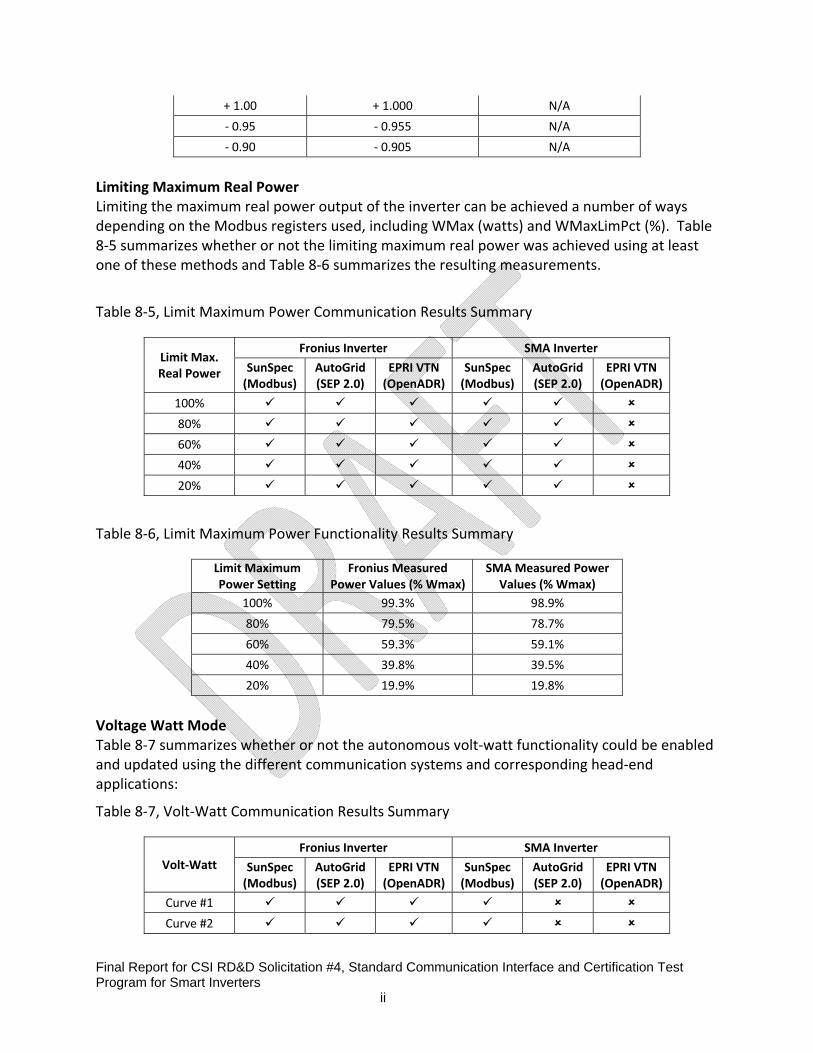
Final Report for CSI RD&D Solicitation #4, Standard Communication Interface and Certification Test Program for Smart Inverters ii
+ 1.00 + 1.000 N/A
‐ 0.95 ‐ 0.955 N/A
‐ 0.90 ‐ 0.905 N/A
Limiting Maximum Real Power Limiting the maximum real power output of the inverter can be achieved a number of ways depending on the Modbus registers used, including WMax (watts) and WMaxLimPct (%). Table 8‐5 summarizes whether or not the limiting maximum real power was achieved using at least one of these methods and Table 8‐6 summarizes the resulting measurements.
Table 8‐5, Limit Maximum Power Communication Results Summary
Limit Max. Real Power
Fronius Inverter SMA Inverter
SunSpec (Modbus)
AutoGrid(SEP 2.0)
EPRI VTN (OpenADR)
SunSpec(Modbus)
AutoGrid (SEP 2.0)
EPRI VTN (OpenADR)
100%
80%
60%
40%
20%
Table 8‐6, Limit Maximum Power Functionality Results Summary
Limit Maximum Power Setting
Fronius MeasuredPower Values (% Wmax)
SMA Measured Power Values (% Wmax)
100% 99.3% 98.9%
80% 79.5% 78.7%
60% 59.3% 59.1%
40% 39.8% 39.5%
20% 19.9% 19.8%
Voltage Watt Mode Table 8‐7 summarizes whether or not the autonomous volt‐watt functionality could be enabled and updated using the different communication systems and corresponding head‐end applications:
Table 8‐7, Volt‐Watt Communication Results Summary
Volt‐Watt
Fronius Inverter SMA Inverter
SunSpec (Modbus)
AutoGrid(SEP 2.0)
EPRI VTN (OpenADR)
SunSpec(Modbus)
AutoGrid (SEP 2.0)
EPRI VTN (OpenADR)
Curve #1
Curve #2

Final Report for CSI RD&D Solicitation #4, Standard Communication Interface and Certification Test Program for Smart Inverters ii
The Fronius inverter only supported 3‐point Volt‐Watt curves as opposed to 4‐point curves. After receiving the appropriate commands from the IEEE 2030.5 application, the Fronius inverter went into a “Sync” mode where it ceased to generate until the grid side conditions were appropriate for 5 minutes. However once it returned to normal operation, the inverter demonstrated autonomous volt‐watt functionality. The SMA inverter acknowledged the write of the volt‐watt curve values, but only updated the first voltage parameter resulting in a failed test.
Figure 8‐6, Sample Voltage‐Watt Test with the Fronius Inverter
Frequency‐Watt Mode The frequency‐watt functionality was ultimately not supported by either inverter manufacturer using open communication protocols, and therefore could not be tested accordingly in the lab. Table 8‐8, Frequency‐Watt Communication Results Summary
Freq‐Watt
Fronius Inverter SMA Inverter
SunSpec (Modbus)
AutoGrid(SEP 2.0)
EPRI VTN (OpenADR)
SunSpec(Modbus)
AutoGrid (SEP 2.0)
EPRI VTN (OpenADR)
Curve #1
Curve #2
Connect/Disconnect Although originally thought to have created physical disconnection from the electric grid, the inverters tested merely used existing functionality to reduce power output. Therefore the real

Final Report for CSI RD&D Solicitation #4, Standard Communication Interface and Certification Test Program for Smart Inverters ii
power output was reduced to near zero, demonstrating something similar to a cease generation capability.
Table 8‐9, Connect‐Disconnect Communication Results Summary
Disconnect
Fronius Inverter SMA Inverter
SunSpec (Modbus)
AutoGrid(SEP 2.0)
EPRI VTN (OpenADR)
SunSpec(Modbus)
AutoGrid (SEP 2.0)
EPRI VTN (OpenADR)
0%
Table 8‐10, Connect‐Disconnect Functionality Results Summary
Ideal Watt Setting Fronius Measured Power SMA Measured Power
0 W 11.3 W 22.1 W
Monitor DER Status and Output Table 8‐11 summarizes the monitoring capabilities of the inverters and the ability to read DER output information from the different communication head‐end systems.
Table 8‐11, Monitoring Communication Results Summary
Monitoring
Fronius Inverter SMA Inverter
SunSpec (Modbus)
AutoGrid(SEP 2.0)
EPRI VTN (OpenADR)
SunSpec(Modbus)
AutoGrid (SEP 2.0)
EPRI VTN (OpenADR)
V, A, W, etc. * *
Though the Autogrid IEEE 2030.5 server did not provide an interface to view or download data, Wireshark traces confirmed the capability of the IEEE 2030.5 systems to post all 7 data points collected by both the Fronius and the SMA inverters. The EPRI OpenADR VTN provided an interface to view and download the data points provided by each of the inverters.
8.2 Sacramento Municipal Utility District Laboratory Testing
Test Environments and Configuration
The following hardware and software components are required to demonstrate the successful exchange of messages between the utility head end and the inverter.

Final Report for CSI RD&D Solicitation #4, Standard Communication Interface and Certification Test Program for Smart Inverters ii
8.2.1.1 Architecture Overview
Utility DER Head End System manages and creates the intended DER programs that will
be communicated to the Smart Inverters and/or aggregators that will act upon the created programs using IEEE 2030.5 (SEP 2.0) or OpenADR 2.0 protocols.
WAN/LAN Network provides the private/public wide area network (or LAN for laboratory usage case) connectivity which will allow the Utility DER Head End System to connect to the grid connected DER devices.
Wi‐Fi Access Point/Router provides the local network connection for the utility’s DER Head End System using the required IPV6 or IPV4 protocol.
SunSpec CEA‐2045 module provides the network connectivity for the target SunSpec based Smart Inverters. This module has the IEEE 2030.5/OpenADR application logic and converts these message exchange protocols to the SunSpec/Modbus register based commands required by the end Smart Inverter DER device.
Inverter Interface Box provides the adapter necessary for the SunSpec CEA ‐2045 module to connect to the end Smart Inverter DER device. This interface box will connect to the end DER device through typically a RS‐485 or TCP Modbus connection.
RS‐485 Sniffer PC – A PC along with serial interface capture and decoding software was used to collected Modbus data exchanges between the CEA 2045 module and the inverters under test.
SunSpec Dashboard – A PC running the SunSpec Dashboard application provided a way to browse register content in the inverter and to make ad hoc changes to those register settings as needed to validate functional behavior.
SunSpec Smart Inverter(s) provide the set of Smart Inverter functionality required by the CA Rule 21 (CSI4 project). Examples of such inverters being tested by the CSI/SMUD project include Fronius and SMA smart inverters.
DC Source ‐ This testing includes used a DC Power Supply as a representation of a PV array.
8.2.1.2 SMUD’s Test Environment

Final Report for CSI RD&D Solicitation #4, Standard Communication Interface and Certification Test Program for Smart Inverters ii
Figure 8‐7, SMUD Laboratory Testing Setup
Utility DER Head End System
A utility owned DER Head End System is the central system that will manage the DER events that will occur in its distribution and residential grid networks. This system will manage the individual inverters and aggregators that will be part of its grid connected inverters/PV systems. The following software was used to simulate the Head End interactions with the Smart Inverters:
QualityLogic IEEE 2030.5 (SEP 2.0) Ad‐Hoc Tester EPRI OpenADR Virtual Top Node (VTN) Application Server, with helper dialogs for inverter specific functions
These components were used to create DER programs and events that were communicated to the participating Smart Inverters.
IEEE 2030.5 (SEP 2.0) OpenADR
Product Name
QualityLogic IEEE 2030.5 Ad‐Hoc Tester
EPRI OpenADR VTN
Software Version
Version 1.1 (Feb 18, 2016) v0.9.5‐2
Technical Reference
QualityLogic Ad‐Hoc Tester Description Note 1
SunSpec‐Modbus‐Usage_CARule21‐Req_Final.pdf

Final Report for CSI RD&D Solicitation #4, Standard Communication Interface and Certification Test Program for Smart Inverters ii
Note 2 1) https://www.qualitylogic.com/tuneup/uploads/docfiles/SEP2‐ad‐hoc‐tester.pdf 2) http://www.epri.com/abstracts/Pages/ProductAbstract.aspx?ProductId=000000003002004788
SunSpec based Inverters
Fronius Inverter A Fronius Smart inverter is one of the two inverters that are the subject of the CSI4 testing. Specifications for the inverter are in the table below:
Hardware Model IG+V6, 0U
Software Version 6.2.28
Options 2.1.21 Modbus Card with RS‐485 Interface ModbusRTU to CEA‐2045 Adapter
Device Address 1
Technical Reference Fronius Modbus Card, Fronius Modbus Register Tables.pdf http://www.fronius.com/Applikationen/contentserverdownload/downloadcsitem.aspx?id=361552
SMA Inverter A SMA Smart inverter is one of the two inverters that are the subject of the CSI4 testing. Specifications for the inverter are in the table below:
Hardware Model SB5000TL‐US‐22
Software Version 40050949
Options 9201 Modbus Protocol with Ethernet TCP Interface Modbus TCP to CEA‐2045 Adapter
Device Address 126
Grid Guard Kitu’s Grid Guard was used.
Technical Reference http://russellpacific.com/wp‐content/uploads/2015/09/Tech_Description_SunSpec_Modbus‐TB‐US‐en‐14.pdf
CEA-2045 Module(s)
The CEA‐2045 modules transform the IEEE 2030.5/OpenADR 2.0 messages into the necessary Modbus register read/write commands to effect the requested inverter function change. The CEA ‐2045 modules are configured to connect to a wireless Wi‐Fi Access point. The table below documents the developers of the four CEA‐2045 modules used during testing along with identifying information, if any, on the modules.
IEEE 2030.5 (SEP 2.0) OpenADR

Final Report for CSI RD&D Solicitation #4, Standard Communication Interface and Certification Test Program for Smart Inverters ii
SMA Inverter
Kitu CEA‐7001 Module
EPRI HW: PiZ16.01.26
FW:TBD
Fronius Inverter
Kitu CEA‐7001 Module EPRI HW: PiZ16.01.26 FW: PIZ16.02.03
Local Area Network Router
A wireless router provides the interconnection between inverter CEA‐2045 modules and the utility head end applications. The following Router Model is used during SMUD’s testing.
Hardware Model ASUS RT‐N16 Wireless‐N 300 Router (DDWRT Compatible)
Software Version Tomato‐K26USB‐1.28.RT‐MIPSR2‐131‐Mega‐VPN.trx
IP Protocol With IPV6 support
The wireless access point on router is preconfigured with a well‐known SSID and Password. The CEA‐2045 module, QualityLogic DER Head End System and other network connected devices and sniffers are connected with this router to communicate SEP 2.0 and OpenADR messages.
Modbus Browsing Software and Hardware
In order to validate that the message exchange between the head end and the inverter was successful, selected inverter Modbus registers were examined. The following applications and associated hardware were utilized to independently inspect and validate the Modbus registers of the inverters:
Item Product Supplier
SunSpec/Modbus Browser
SunSpec Dashboard SunSpec Alliance
USB to RS‐485 Adapter
RS‐485 to USB Converter is required to connect the SunSpec Dashboard or any Modbus sniffing software from a PC laptop
Any RS‐485 to USB converter manufacturer
An Ethernet cable or wireless interface is required to connect the PC running the Modbus TCP browser to the SMA inverter's Modbus TCP RJ45 connector.

Final Report for CSI RD&D Solicitation #4, Standard Communication Interface and Certification Test Program for Smart Inverters ii
Electrical Setup
The Smart Inverters being tested were connected electrically to a DC power supply (Agilent N5771A 300VDC, 5A Power Supply) to simulate the Photovoltaic Arrays. The inverters were not attached to the AC power grid.
Summary of SMUD’s Test Observations
The following highlights some of the more significant observations during testing. Please refer to each detailed test section as well as the test logs in the appendix for more information on the behavior of the inverters, CEA‐2045 modules, and the applications simulating the Head End events.
Not all of the required CSI inverter modes are supported by either of the Smart Inverters tested.
Frequency Watt curve mode is not supported in both Fronius and SMA inverter models.
Current inverters have some limitations on the ability to write certain Modbus registers, ex. OutPFSet_Ena register for SMA which enables/disables Fixed Power Factor mode.
The CEA‐2045 modules for Fronius inverters do not have sufficient torque on fasteners and individual pin insertion depth.
Both inverters require a DC power to be provided in order for a client to more fully read its SunSpec based registers.
IEEE 2030.5 does not have a way to issue connect/disconnect commands in the current standard. It is only a state information as part of the DERSettings attributes.
EPRI OpenADR 2.0b module successfully received inverter function events from the Headend VTN, but in most cases the module failed to send the required Modbus values to the SMA inverter.
The communication systems did not always return the smart inverter to its previous state at the end of an event, such as modifying power factor.
Unexpected behavior when attempting to enable some inverter functions, such as entering into startup mode when enabling Voltage‐Watt Mode (Fronius)
8.2.8.1 Registration
Summary: Registration encompasses all communication set up procedures and is a pre‐condition for the remainder of the test cases. Registration comprises the registration of devices on servers, automated server and resource discovery processes, network commissioning, and provisioning of server information on clients (IP Addresses, URLs, program information, etc.). The purpose of

Final Report for CSI RD&D Solicitation #4, Standard Communication Interface and Certification Test Program for Smart Inverters ii
this test case is to ensure interoperability of various technologies, architectures, and standards, and is fundamental to meeting the objectives of the CSI4 project.
Results:
Test Case IEEE 2030.5 QLI DER Head End/Kitu CEA‐2045
OpenADR 2.0 EPRI VTN/EPRI CEA‐2045
Fronius SMA Fronius SMA
Registration √ √ √ √
Test Observations:
Communication between the OpenADR EPRI CEA‐2045 (OpenADR) modules and the VTN used HTTP communication with basic authentication rather than TLS 1.2 security with client server x.509 certificate exchange used in most deployments. EPRI reports that the module is capable of both, and was operated in basic authentication mode for this project in order to work with an existing basic OpenADR server instance.
8.2.8.2 Volt‐VAR Mode with Watt Priority
Summary: The Volt/var function allows DER systems to counteract voltage deviations from the nominal voltage level (but still within normal operating ranges) by consuming or producing reactive power. Volt/var curves can specify the changes in vars in response to changes in the local voltage measured at the inverter terminals.
Results:
Test Case IEEE 2030.5 QLI DER Head End/Kitu CEA‐2045
OpenADR 2.0 EPRI VTN/EPRI CEA‐2045
Fronius SMA Fronius SMA
Volt‐Var √* √* √* Χ*
Test Observations:
Fronius: inverter does not support %VArAvail (Mode 3) which is the method by which CSI Test Plan recommends for controlling Volt‐VAr inverter control. It supports use of %VArMax (Mode 2), The Kitu CEA 2045 (SEP 2.0) module for this test case attempts to write mode 2 to the DeptRef register, while the EPRI OpenADR 2.0b module attempts to write mode 0 (N/A) to the DeptRef register. Volt‐VAr:DeptRef register is read only and fixed at DeptRef=2 (%VArMax), so neither of these write attempts had an effect on the mode used.
SMA: Although the inverter allows writing of 8 curve points along with setting the enable bit by the CEA 2045 (SEP 2.0) module, it only updates the first curve point coordinates and the enable bit does not get set.
SMA: inverter does not support %VArAvail (Mode 3) which is the method by which CSI Test Plan recommends for controlling Volt‐VAr inverter control. It supports use of %WMax (Mode 1) which is used by the Kitu CEA‐2045 (SEP 2.0) module for this test case.

Final Report for CSI RD&D Solicitation #4, Standard Communication Interface and Certification Test Program for Smart Inverters ii
Volt‐VAr:DeptRef register is read only and fixed at DeptRef=1 (%WMax) according to the SMA technical documentation. However, the SunSpec dashboard reads the value as 0.02 and CEA 2045 module reads it as 2, which made no impact on the test itself.
SMA: Modbus sniffer log indicates that EPRI CEA‐2045 (OpenADR) module does not attempt to read or write any Volt/Var settings.
8.2.8.3 Fixed Power Factor
Summary: The purpose of utilizing fixed power factors in an inverter‐based DER system is to help compensate for any reactive load and/or other DER systems that generate reactive power. Ideally, the most efficient operation of an electric power system is if it has zero reactive power and a unity power factor. However different types of loads and DER systems can generate/consume reactive power, adjusting the power factor on the circuit and limiting real power flow over conductors. If the inverter’s fixed power factor can be modified to meet reactive power demand, then this will allow circuit feeders to maintain optimal real power flow.
Results:
Test Case IEEE 2030.5 QLI DER Head End/Kitu CEA‐2045
OpenADR 2.0 EPRI VTN/EPRI CEA‐2045
Fronius SMA Fronius SMA
Fixed Power Factor √* Χ* √* Χ*
Test Observations:
Fronius (SEP 2.0): Inverter appears to always behave in the default mode of unity Power Factor operation as the specific enable register (OutPFSet_Ena) is left clear.
Fronius (OpenADR): After event, inverter doesn’t return to original OutPFSet, or clear OutPFSet_Ena. Modbus trace indicates Modbus Error 3 when the CEA module attempts to write a value of 0 to the OutPFSet register at the end of the event. The trace indicates that the CEA module does not try to write any other registers at the end of the event.
SMA: Inverter does not allow turning off the Power Factor Enable register (OutPFSet_Ena) as it always remains at 1. Attempting to turn it off results in a Modbus error 1.
SMA: Inverter does not support setting a user specified Power Factor value at all. Attempting to write to the appropriate inverter register results in a Modbus error 2.
8.2.8.4 Limit Maximum Real Power
Summary: While solar photovoltaic generation is dependent on solar irradiance and can therefore be intermittent throughout the day, the DER system settings can be modified to place a maximum limit on amount of real power generated. Limiting maximum real power may be necessary in response to unusual or emergency conditions that are causing reverse flow into the feeder’s substation or because the total DER real power output on the feeder is greater than some

Final Report for CSI RD&D Solicitation #4, Standard Communication Interface and Certification Test Program for Smart Inverters ii
percentage of total load, which can potentially result in higher voltages on the distribution feeder. This test case will cover the above use case by initiating a series of Limit Maximum Real Power commands from the Utility DER Head End system to the target smart inverter device using the values from Table 4 below.
Results:
Test Case IEEE 2030.5 QLI DER Head End/Kitu CEA‐2045
OpenADR 2.0 EPRI VTN/EPRI CEA‐2045
Fronius SMA Fronius SMA
Limited Max Real Power √* √ √* Χ*
Test Observations:
Fronius (SEP 2.0): The Kitu CEA‐2045 modules forces the inverter to go into sleep mode if it detects the value of WMaxLimPct to be 0 (checks it before/after the actual test). It is uncertain if this is the intended functionality.
Fronius: Although Fronius allows writing into Setting:WMax register, it is actually read‐only and does not change the value.
Fronius (OpenADR) ‐ At completion of the event, CEA module sets WMaxLimPct to 0, instead of 100%. This is acceptable, but the expected post‐event setting is ambiguous. WMaxLim_Ena left clear, perhaps appropriate since 100% isn’t really imposing a limit.
SMA: WMaxLimPct register is write only, so unable to verify that setting is applied by inverter because reading is not allowed.
SMA: Unable to clear WMaxLim_Ena using SSDash, so it is always 1.
SMA: When limiting Max Real Power using OpModFixed Flow event mode, the CEA2045 (SEP 2.0) module attempts to write to the Wmax setting only and not the WMaxLimPct and WMaxLim_Ena event controls.
SMA: Modbus sniffer log indicates that the EPRI CEA‐2045 (OpenADR) module does not attempt to write to the WMaxLimPct, WMaxLim_Ena, or WMax register settings.
8.2.8.5 Voltage‐Watt Mode
Summary: The DER system autonomously modifies real power output in order to dampen voltage deviations. The purpose of voltage‐watt operations is to use DER systems to help maintain voltage levels within their normal ranges as an alternative to emergency tripping in cases where an abundance of generation is resulting in higher voltages on the feeder. These higher voltages could be the result of reverse power flow on small conductors. The inverter would follow a voltage‐watt curve that would specify the maximum real power output in response to the measured voltage at the inverter terminals.
Results:
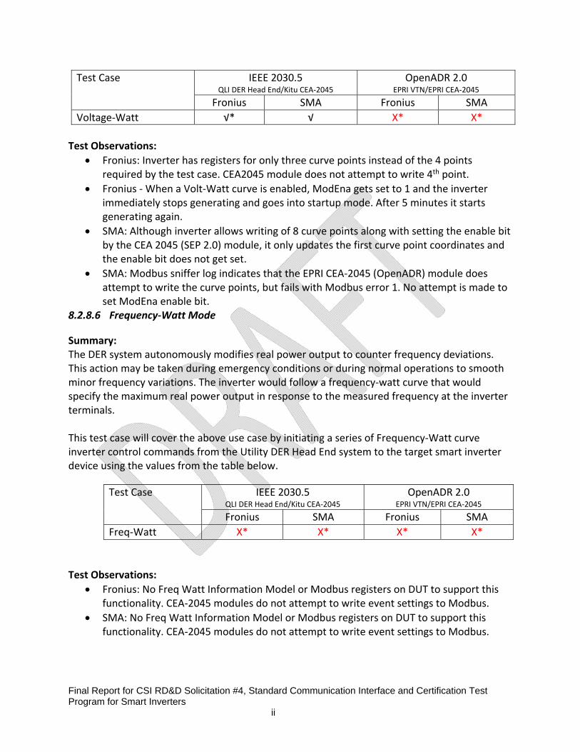
Final Report for CSI RD&D Solicitation #4, Standard Communication Interface and Certification Test Program for Smart Inverters ii
Test Observations:
Fronius: Inverter has registers for only three curve points instead of the 4 points required by the test case. CEA2045 module does not attempt to write 4th point.
Fronius ‐ When a Volt‐Watt curve is enabled, ModEna gets set to 1 and the inverter immediately stops generating and goes into startup mode. After 5 minutes it starts generating again.
SMA: Although inverter allows writing of 8 curve points along with setting the enable bit by the CEA 2045 (SEP 2.0) module, it only updates the first curve point coordinates and the enable bit does not get set.
SMA: Modbus sniffer log indicates that the EPRI CEA‐2045 (OpenADR) module does attempt to write the curve points, but fails with Modbus error 1. No attempt is made to set ModEna enable bit.
8.2.8.6 Frequency‐Watt Mode
Summary: The DER system autonomously modifies real power output to counter frequency deviations. This action may be taken during emergency conditions or during normal operations to smooth minor frequency variations. The inverter would follow a frequency‐watt curve that would specify the maximum real power output in response to the measured frequency at the inverter terminals. This test case will cover the above use case by initiating a series of Frequency‐Watt curve inverter control commands from the Utility DER Head End system to the target smart inverter device using the values from the table below.
Test Observations:
Fronius: No Freq Watt Information Model or Modbus registers on DUT to support this functionality. CEA‐2045 modules do not attempt to write event settings to Modbus.
SMA: No Freq Watt Information Model or Modbus registers on DUT to support this functionality. CEA‐2045 modules do not attempt to write event settings to Modbus.
Test Case IEEE 2030.5 QLI DER Head End/Kitu CEA‐2045
OpenADR 2.0 EPRI VTN/EPRI CEA‐2045
Fronius SMA Fronius SMA
Voltage‐Watt √* √ X* X*
Test Case IEEE 2030.5 QLI DER Head End/Kitu CEA‐2045
OpenADR 2.0 EPRI VTN/EPRI CEA‐2045
Fronius SMA Fronius SMA
Freq‐Watt Χ* Χ* Χ* X*

Final Report for CSI RD&D Solicitation #4, Standard Communication Interface and Certification Test Program for Smart Inverters ii
8.2.8.7 Connect/Disconnect
Summary: This particular function causes the DER system to electrically connect or disconnect from the grid. This may be implemented in response to an unusual or emergency condition requiring the DER system to be de‐energized. The DER equipment may be disrupting the grid due to malfunctioning behavior or the resource may need to be disconnected for maintenance. This test case will cover the above use case by initiating a Connect/Disconnect inverter control commands from the Utility DER Head End system to the target smart inverter device. Results:
Test Case IEEE 2030.5 QLI DER Head End/Kitu CEA‐2045
OpenADR 2.0 EPRI VTN/EPRI CEA‐2045
Fronius SMA Fronius SMA
Connect/Disconnect √* √* √* X*
Test Observations:
Fronius: Remains disconnected after event expires, but enters Sync Mode and automatically Connects after 5 minutes.
Fronius: Event works, but causes DUT to enter sync mode. After 5 minutes in Sync mode it reconnects.
o Question: Should a disconnect command have a predetermined time limit after which it causes the inverter to reconnect? If disconnected for safety reasons, shouldn't it remain so until conditions are determined safe and a Connect command supersedes it? For that matter when is it ever safe to Connect an inverter remotely, given that ground crews may not expect it? Should connect/disconnect be a static setting or time based event?
SMA: WLimMax_Ena is always 1 and cannot be cleared by the SunSpec Dashboard. Causes a Modbus exception 1.
SMA: Modbus trace indicates that the CEA Module successfully clears the Connected register, clears WMaxLimPct, and sets WMaxLim_Ena. The SunSpec Dashboaed is unable to read the write‐only Connected register. The inverter reduces its generation output, but the inverter display panel and DC Power Supply are still indicating production of 300V at .1A.
SMA: Modbus sniffer log indicates that the EPRI CEA‐2045 (OpenADR) module does not attempt to write to Conn, WMaxLimPct, or WLimMax_Ena registers with event settings. No change to AC output power of inverter.
8.2.8.8 Monitor DER Status and Output
Summary: DER systems connected to the utility distribution system will be required to have monitoring capabilities that provide operational state data. This may include the system status (i.e.

Final Report for CSI RD&D Solicitation #4, Standard Communication Interface and Certification Test Program for Smart Inverters ii
connected/disconnected) as well as various power system measurements (watts, vars, voltage, etc.). This test case will cover the above use case by initiating a set of inverter monitoring commands from the Utility DER Head End system to the target smart inverter device. Results:
Test Case IEEE 2030.5 QLI DER Head End/Kitu CEA‐2045
OpenADR 2.0 EPRI VTN/EPRI CEA‐2045
Fronius SMA Fronius SMA
Monitor DER Status √* √* √ √
Test Observations: Modbus traces indicates that the Kitu CEA‐2045 (SEP 2.0) module is not requesting Current(A) and Voltage (V). Posts are fixed at 655350 and 21300 respectively.
8.3 EPRI Supplemental Laboratory Testing
EPRI conducted supplemental testing to better understand some of the results conducted by the utilities. This included investigating issues identified in the results and understanding differences in functionality between the AutoGrid module and the EPRI module. The investigation required a deep dive into the implementation of SunSpec in the devices which revealed a few key leaning points. More focus was put on testing where the utilities identified differences in how the SunSpec Dashboard, AutoGrid module, and EPRI module performed. This occurred more often with the SMA so the results are more detailed for the SMA compared to the Fronius.
Figure 8‐8 EPRI’s’ laboratory setup.
EPRI Laboratory Test Results Summary The results below summarize the support of each inverter for the registers defined in the SunSpec Specification. The results do not reflect the functionality of any non‐SunSpec registers or manufacturer specific functionality. The Fronius was connected to a DC Power supply in testing. The SMA was connected to PV Simulator. Both inverters were connected to the local grid.

Final Report for CSI RD&D Solicitation #4, Standard Communication Interface and Certification Test Program for Smart Inverters ii
A new firmware was released by SMA during the EPRI supplemental testing. All of the utility and UL testing was performed using FW Pack 2.63. The newly release version was FW Pack 2.65. Differences in performance between the two are identified below on a function by function basis. In general, the new firmware was almost identical with a couple exceptions. In all cases it appeared the differences were improvements. All of the electrical characteristics were captured using the most recent firmware – FW Pack 2.65
Table 8‐12, Model Software Version for the Inverters Tested
Fronius SMA
Model IG Plus Advanced SB5000TL‐US‐22
Software Version 6.2.28 (2.1.21 ‐Modbus Card) 2.65.03
It should be noted that the SMA requires a Grid Guard Code to be entered before operational parameters can be changed in the inverter. Software was added to the EPRI VTN module to enter a code before sending commands. An alternative approach, and the one taken for SunSpec Dashboard testing, was to enter it using a Modbus utility tool. The Grid Guard code lasts for 10 hours or until the inverter is powered off.
Table 8‐13, Summarized Test Results from EPRI’s Supplemental Testing
Test Case
Fronius Inverter SMA Inverter SunSpec(Modbus)
EPRI VTN(OpenADR)
SunSpec (Modbus)
EPRI VTN(OpenADR)
Limit Max Real Power Fixed Power Factor Ramp Rate (WGra)
Connect / Disconnect Volt‐Var Curve * Volt‐Watt Curve *
Frequency/Watt Curve Ramp Rate
DER Monitoring Points *The volt‐var and volt‐watt modes functioned electrically however the curves had to be programmed one point
at a time which prevented the EPRI VTN from controlling it. See full test results for more details.
A high‐level summary of the results is found in Table 8‐13. It is important to understand that each function contains a series of parameters to control the function. This includes timers (randomized start window, reversion timer), ramp rates specific to the function, on/off control, and other input parameters. Not all of these parameters are required for the function to operate. In EPRI’s testing a function was considered supported if it had enough of these parameters to create an electrical response (watts, vars). Timers and function specific ramp rates were not tested thoroughly. The specific parameters required in the field may differ from what was tested depending on grid codes and the requirements of the customers (utilities, homeowners, and building owners).

Final Report for CSI RD&D Solicitation #4, Standard Communication Interface and Certification Test Program for Smart Inverters ii
Volt‐VAR Mode Note: The values on the dependent axis can be changed for curves allowing it to function differently for different use‐cases. This is controlled by the DeptRef flag. In the case of Volt‐Var the options include percent of maximum VARs (rating), percent of VARs available (only produces as many VARs available at the current power output – prioritizes power generation over VARs), and percent of wattage rating. Each of these are communicated by passing either 1, 2, or 3 to the DeptRef variable. SMA: The SMA supports Volt‐Var Mode. Writing curves to Volt‐Var Mode behaved oddly.
SunSpec Dashboard: The SMA supports the necessary points to implement Volt‐Var Mode including on/off control (ModEna)and active curve (ActCrv). It supports a single, twelve‐point volt‐var curve. It did not support the three timers or ramp rates. The inverter only supported percent of maximum VARs (rating). DeptRef was set to read only so writing to it always returned a Modbus exception error if written.
Figure 8‐9, Volt‐Var Function, Reactive Power vs.AC Voltage for SMA
EPRI VTN (OpenADR): The EPRI VTN did not support Volt‐Var Mode on the SMA. Three issues were identified. Two we corrected during testing.
1. A utility test report helped identify a bug in the SunSpec Library used by the EPRI module. Once this bug was corrected the module attempted to communicate with the inverter.
2. The EPRI module was sending an invalid DeptRef value to the inverter. There was a bug in the code where the EPRI VTN passes 0, an invalid entry. The bug was corrected by accepting the default DeptRef value. This topic is discussed further in the findings below.
3. The SMA does not allow multiple points to be changed in a single Modbus message. It does not throw an error however it only stores the first value received (V1). In a separate test EPRI sent a curve one point at a time and was able to populate a curve, turn it on, and observe the inverter adjust its power output based on voltage. The behavior of accepting a single value at a time is unfavorable and not likely in conformance with Modbus standard.

Final Report for CSI RD&D Solicitation #4, Standard Communication Interface and Certification Test Program for Smart Inverters ii
Fronius: The Fronius supports Volt‐Var Mode.
SunSpec Dashboard: The SMA supports the necessary points to implement Volt‐Var Mode including on/off control (ModEna)and active curve (ActCrv). It supports four, four‐point volt‐var curves. It also supported timers and ramp rates specific to the function. The inverter only supported percent of maximum VARs (rating). DeptRef was set to read/write but all values written were ignored. Reading the register always returned percent of maximum VARs.
Figure 8‐10 Volt‐Var Function, Reactive Power vs.AC Voltage for Fronius
EPRI VTN (OpenADR): The functions behave as expected. Parameters are passed to the SunSpec registers and they produce an electrical response.
Fixed Power Factor SMA: The SMA does not support Fixed Power Factor mode.
SunSpec Dashboard: The function is unsupported however some parameters appear on the SunSpec Dashboard. In the firmware version tested in this project (FW Pack 2.63) some parameters were available to be changed but produced errors when used. In most cases writing to these parameters returned a Modbus exception error for Illegal Data

Final Report for CSI RD&D Solicitation #4, Standard Communication Interface and Certification Test Program for Smart Inverters ii
Address. An update to the most recent, publically available firmware (FW Pack 2.65) completely removed these parameters indicating the function was unsupported. EPRI VTN (OpenADR): The function is unsupported so the C library created by SunSpec does not attempt to write to the parameters.
Fronius: The Fronius supports Fixed Power Factor mode.
SunSpec Dashboard: The Fronius supports the necessary points to implement Fixed Power Factor including on/off control (WMaxLim_Ena) and power factor selection (OutPFSet). It also supported timers and ramp rates specific to the function.
Figure 8‐11 Power Factor Test Results for Fronius

Final Report for CSI RD&D Solicitation #4, Standard Communication Interface and Certification Test Program for Smart Inverters ii
Figure 8‐12 VAR Preference with Fixed Power Factor Function for Fronius
EPRI VTN (OpenADR): The functions behave as expected. Parameters are passed to the SunSpec registers and they produce an electrical response.
Limit Maximum Real Power SMA: The SMA does not support Limit Maximum Real Power.
SunSpec Dashboard: The function is unsupported but some parameters appear on the SunSpec Dashboard. The SMA supports the on/off parameter (WMaxLim_Ena) but does not allow the user to turn it off once enabled. The SMA does not support the parameter to control output power (WMaxLimPct) as defined in the SunSpec Specification. The parameter can be written to but not read. Technically a user can write to this parameter can produce an electrical response but because SunSpec Specification requires it to be readable and writable this function is deemed unsupported by the library. EPRI VTN (OpenADR): The function is unsupported so the C library created by SunSpec does not attempt to write to the parameters.
Fronius: The Fronius supports Limit Maximum Real Power.

Final Report for CSI RD&D Solicitation #4, Standard Communication Interface and Certification Test Program for Smart Inverters ii
SunSpec Dashboard: The Fronius supported the parameter to control output power (WMaxLimPct) and the on/off parameter (WMaxLim_Ena). These were the only two parameters required in EPRI’s test. It was noted that the Fronius also supports the timers and the ramp rate specific to the function.
Figure 8‐13 Maximum Power Limit Function Real Power vs. Power Limit Setting for Fronius
EPRI VTN (OpenADR): The functions behave as expected. Parameters are passed to the SunSpec registers and they produce an electrical response. Scheduling from the EPRI VTN was tested for this function. It was only tested for this function because bugs had been reported on this function. Start and stop times sent from the EPRI VTN were followed by the inverter.
Volt‐Watt Mode Note: The values on the dependent axis can be changed for curves allowing it to function differently for various use‐cases. This is controlled by the DeptRef flag. In the case of Volt‐Watt the options include percent of maximum watts (rating) and percent of watts available. Each of these are communicated by passing either 1 or 2 to the DeptRef variable.

Final Report for CSI RD&D Solicitation #4, Standard Communication Interface and Certification Test Program for Smart Inverters ii
SMA: The SMA supports Volt‐Watt Mode. Writing curves to Volt‐Watt Mode behaved oddly.
SunSpec Dashboard: The SMA supports the necessary points to implement Volt‐Watt Mode including on/off control (ModEna)and active curve (ActCrv). It supports a single, eight‐point volt‐watt curve. It did not support the three timers or ramp rates. The SMA is locked into WAvailable mode. The inverter only supported percent of watts available. This may be a bug in the code as the inverter behaved as expected for percent of maximum watts (rating). DeptRef was set to read only so writing to it always returned a Modbus exception error if written.
Figure 8‐14 Volt‐Watt Function, Real Power vs. AC Voltage for SMA
EPRI VTN (OpenADR): The EPRI VTN did not support Volt‐Watt Mode on the SMA. Two issues were identified. One was corrected during testing.
1. The EPRI module was sending an invalid DeptRef value to the inverter. The EPRI VTN only supported WMax while the Fronius only supported WAvailable. A change was made during the testing to accept the default value however this is not ideal. EPRI applied the change for the sake of testing. The module now accepts the default DeptRef value. This topic is discussed further in the findings below.
2. The SMA does not allow multiple points to be changed in a single Modbus message. It does not throw an error however it only stores the first value received (V1). In a separate test EPRI sent a curve one point at a time and was able to populate a curve, turn it on, and see the inverter adjust its power output based on voltage. The behavior of accepting a single value at a time is unfavorable and not likely in conformance with Modbus standard.
Fronius: The Fronius supports Volt‐Watt Mode.

Final Report for CSI RD&D Solicitation #4, Standard Communication Interface and Certification Test Program for Smart Inverters ii
SunSpec Dashboard: The Fronius supports the necessary points to implement Volt‐Watt Mode including on/off control (ModEna)and active curve (ActCrv). It supports four, 3‐point volt‐watt curves. It also supports timers and ramp rates specific to the function. The inverter only supported percent of watts available. DeptRef was set to read/write but all values written were ignored. Reading the register always returned watts available (DeptRef=2). Testing revealed three interested items about Fronius’ implementation of Volt‐Watt.
1. Testing revealed that to make changes to the volt‐watt parameters, an order of operations had to be followed. Parameters had to be turned off to make changes to others. Once this order is established the function operated as expected.
2. If the volt‐watt function was altered, it caused the inverter to go into standby
mode and then reconnect. This happened if the curve was turned on or off using ModEna or if any of the four curves were changed while ModEna was set to 1. There also seemed to be residual effects on other functions if they were changed around the time when volt/watt was active causing the inverter to restart.
3. The Fronius appears to verify volt‐watt curves in two ways. First, the first two
wattage values (three total) were locked to 100%. Writing anything other than 100% did not produce errors but the value was replaced by 100% when read. Second, the inverter returned Modbus Error 3, Illegal Data Value, if voltages were not in increasing order. Both of these behaviors follow the expected shape for a volt‐watt curve however the same behavior was not noticed in other functions.

Final Report for CSI RD&D Solicitation #4, Standard Communication Interface and Certification Test Program for Smart Inverters ii
Figure 8‐15 Volt‐Watt Function, Real Power vs. AC Voltage for Fronius
EPRI VTN (OpenADR): The functions behave as expected. Parameters are passed to the SunSpec registers and they produce an electrical response as long as the order of operations mentioned above is followed.
Frequency‐Watt Mode Note: Frequency‐Watt mode comes into two forms. Function 1 uses parameters to control the behavior of the inverter in reference to deviation from nominal frequency. This parameter can also provide a hysteresis effect. Function 2 is curve based where the user provides data points to create a curve. SMA: The SMA supports as Function 2.
SunSpec Dashboard: The SMA supports all the required parameters for Function 2 of the Frequency‐Watt curve.
Figure 8‐16 Frequency‐Watt Function, Real Power vs. AC Voltage for Fronius

Final Report for CSI RD&D Solicitation #4, Standard Communication Interface and Certification Test Program for Smart Inverters ii
EPRI VTN (OpenADR): Frequency‐Watt is supported by the EPRI VTN but only for Function 1, the curve based Frequency‐Watt Mode. The EPRI VTN was not able to control Frequency‐Watt Mode on the SMA because the SMA only supports Function 2 of Frequency‐Watt Mode.
Fronius: The Fronius does not support Frequency‐Watt Mode.
SunSpec Dashboard: The function is unsupported and does therefore not appear on the SunSpec Dashboard. EPRI VTN (OpenADR): The function is unsupported so the C library created by SunSpec does not attempt to write to the parameters.
Connect/Disconnect Mode Note: Connect/Disconnect is a mode that allows a user to connect or disconnect an inverter. A disconnect can take two forms: 1) physical operation of a switch and 2) setting output to 0 / ceasing to energize. SMA: The SMA does not support Connect/Disconnect.
SunSpec Dashboard: The function is unsupported and does therefore not appear on the SunSpec Dashboard. EPRI VTN (OpenADR): The function is unsupported so the C library created by SunSpec does not attempt to write to the parameters.
Fronius: The Fronius supports the on/off parameter for connect/disconnect.
SunSpec Dashboard: The Fronius supports connect disconnect. When disconnected the Fronius takes the second approach mentioned above, cease to energize. The Fronius supports the required Connect/Disconnect parameter (Conn) and both timers (Conn_WinTms, Conn_RvrtTms). EPRI VTN (OpenADR): The function behaves as expected. Parameters are passed to the SunSpec registers and they produce an electrical response.
Ramp Rate There are two types of ramp rates in the SunSpec Specification. A general ramp rate (WGra) and function specific ramp rates. This function, Ramp Rate, only controls the general ramp rate. All function specific ramp rates are nested within their applicable function. If a function specific ramp rate is entered, it takes precedence over the general ramp rate.

Final Report for CSI RD&D Solicitation #4, Standard Communication Interface and Certification Test Program for Smart Inverters ii
SMA: The SMA supports ramp rate (WGra).
SunSpec Dashboard: The ramp rate parameter did not behave properly in the firmware version tested in this project (FW Pack 2.63). Values written to the register did not read back as the same value. Once updated to the newest release version (FW Pack 2.65) the ramp rate function worked as expected.
EPRI VTN (OpenADR): The EPRI VTN passes the ramp rate to the inverter.
Fronius: The Fronius does not support ramp rate (WGra).
SunSpec Dashboard: The function is unsupported and therefore does not appear on the SunSpec Dashboard. EPRI VTN (OpenADR): The function is unsupported so the C library created by SunSpec does not attempt to write to the parameters.
Monitor DER Status and Output This project only required a subset of the measurement points supported by the two inverters. The required parameters are shown below in Table 8‐14. Table 8‐14, Summary of Monitoring Test Results for SunSpec Dashboard and VTN
Test Case
Fronius Inverter SMA Inverter Supported Units Supported Units
Total Real Energy Output Watt‐Hours Watt‐Hours
Alarm Flags / Status Monitoring
Various Status Points Supported Various Status Points Supported
AC Voltage at ECP Van Vab, Van, Vbn
AC Real Power W W
AC Reactive Power VARs, OF VARs
Power Factor PF Line Frequency Hz Hz
SMA: The SMA supports status monitoring points.
Figure 8‐17, Voltage Measurement Comparison for SMA

Final Report for CSI RD&D Solicitation #4, Standard Communication Interface and Certification Test Program for Smart Inverters ii
SunSpec Dashboard: The SMA supported the following status monitoring points.
Figure 8‐18, Status monitoring points supported by the SMA Inverter
EPRI VTN (OpenADR): The supported functions are summarized in Table 8‐14. It was observed that sometimes the inverter would return invalid data. Further investigation found that the inverter did not always return a full list of monitoring points. This occurred on both inverters. It would often correctly transmit all the supported monitoring points at the next reporting interval.
Fronius: The Fronius supports status monitoring points.
Figure 8‐19, Voltage Measurement Comparison for Fronius

Final Report for CSI RD&D Solicitation #4, Standard Communication Interface and Certification Test Program for Smart Inverters ii
SunSpec Dashboard: The Fronius supported the following status monitoring points.
Figure 8‐20, Status monitoring points supported by the Fronius. Snapshot of the SunSpec Dashboard.
EPRI VTN (OpenADR): The supported functions are summarized in Table 8‐14. It was observed that sometimes the inverter would return invalid data. Further investigation found that the inverter did not always return a full list of monitoring points and would fill in this unreported data with the maximum value for the data type – a value that corresponds to “not implemented”. This occurred on both inverters. It would often correctly transmit all the supported monitoring points at the next reporting interval.
Key Findings
Both inverters successfully supported some of the functions and had issues with others. The SMA had a number of issues with how the functions were implemented but it appears that SunSpec interoperability is within sight for them. Many of the functions did not behave ideally however the functions worked with a few tweaks. In the course of this project many changes were made to the firmware, each one advancing the inverter a bit further forward. The Fronius had a couple issues but it appeared that the functions that were implemented were implemented fully. Future Research Opportunities: In both cases conformance testing, plug fests, and interoperability events will help identify these issues over time.
DeptRef is a parameter that should be evaluated. The modes that use DeptRef change in functionality depending on which DeptRef is set. The two inverters tested did not always implement the same DeptRef. Future Research Opportunities: A dashboard or top node should either make it clear to users what DeptRef is default or provide users with a choice. The inverters should also be able to communicate which modes are supported or provide meaningful error

Final Report for CSI RD&D Solicitation #4, Standard Communication Interface and Certification Test Program for Smart Inverters ii
messages back to the user. It is likely that grid codes and utilities will require specific deptref values in interconnection agreements. If this is the case, the supported DeptRefs across management tools and inverters will converge on these requirements.
SMA’s Grid Guard® feature required changes to the EPRI’s OpenADR module that are custom for the SMA. A custom approach was taken to support this outside of SunSpec. Future Research Opportunities: It may be beneficial to address whether these types of access protection keys should be handled by SunSpec and if so, how to transmit them.
The SMA only allows curves to be written one point at a time. Future Research Opportunities: Though feasible, this may not be the ideal implementation for wide‐scale implementation.
The Fronius power cycles at the beginning and end of volt‐watt operation and when changes are made to the parameters. The function also requires an order of operation to enable volt‐watt curves. Future Research Opportunities: This behavior is easily adapted to on an individual basis but may be more difficult when controlling a large set of inverters. The impact of this behavior will need to be studied to understand their impact on a larger scale.

Final Report for CSI RD&D Solicitation #4, Standard Communication Interface and Certification Test Program for Smart Inverters ii
9 FIELD TESTING
The laboratory testing was followed by field testing by both SCE and SMUD. The purpose of the field testing was to re‐assess the communication systems and inverters in actual environments. Specifically:
The communication system signal strengths may be ideal in laboratory environments but weak in field environments. This is of particular concern when small communication modules are used because their antenna geometries typically do not have the gain or range that larger equipment has.
Communication system noise levels may be higher. Laboratory tests can inadvertently create ideal circumstances that are not common in the field.
Communication system activity may be higher. In field environments, the communication systems may be active supporting other uses and this activity could impact the test results.
Inverter operation may differ when fed from actual PV panels instead of a PV simulator.
Inverter operation may differ when connected to an actual AC grid voltage (e.g. voltage variability, noise) rather than a grid simulator.
Per the project scope and plan, the scale of the field tests was the same as the laboratory testing. Multiple inverters at multiple sites would have provided more insight into the field communication scenarios.
9.1 Southern California Edison Field Testing
<to be added here>
9.2 Sacramento Municipal Utility District Field Testing
<to be added here>
Final Report for CSI RD&D Solicitation #4, Standard Communication Interface and Certification Test Program for Smart Inverters ii
10 CONCLUSIONS
This project was timely in that the execution ran in parallel with and accelerated important industry activities:
SIWG Recommendations
CA Rule 21 Revisions
IEEE 1547a Amendment
IEEE 1547 Full Revision
IEC 61850‐7‐420 and IEC 61850‐7‐520 revisions in TC57 WG17
EPRI Common Functions, 4th Edition, 2016
UL 1741 SA
EPRI DER Group‐Level Integration Initiative
10.1 Positive Outcomes
Rule 21 Functionality is Achievable. The project found that the CA Rule 21 Phase 1 functionalities are practical and supportable, even by small scale residential inverters. This is an important finding and informs industry discussions regarding what sizes of DER might be able to provide grid support. SunSpec Protocol Interoperability. The project found that the SunSpec Modbus protocol could be used to achieve interoperability of smart inverters based on a core set of monitoring and management functions. Project partners Fronius and SMA were able to produce products that supported required functionality and interoperated to varying degrees. Modular Communication Interface. This project utilized a modular communication approach in which the inverters were made with a standard CEA‐2045 port interface and each communication system provider produced a standard communication module that could plug‐into the ports and bring the inverters onto their network. The project demonstrated that such an approach can enable smart inverters to be communication‐system flexible and to work with any network type. IEEE 2030.5 Protocol. The project successfully applied the existing IEEE 2030.5 protocol in one of the communication networks (from the utility head‐end to a gateway that then connected to the communication modules on the Fronius and SMA inverters) to support the California Rule 21 control and monitoring functions. OpenADR 2.0b Protocol. The project was able to adapt the OpenADR 2.0b protocol in order to support Rule 21 functionality. It is noted that OpenADR's specified Event types do not inherently support Rule 21 inverter functions. However, using OpenADR's flexible tool box of Event characteristics, it was straightforward to build conformant OpenADR Event payloads that could encapsulate the inverter function settings. The project team was able to show the

Final Report for CSI RD&D Solicitation #4, Standard Communication Interface and Certification Test Program for Smart Inverters ii
network flexibility achieved by the SunSpec/CEA‐2045 interface and that OpenADR 2.0b could be used to communicate information to the smart inverters.
10.2 Challenges
Timing of Parallel Industry Activities. When this project started in 2014, it was not possible to know the exact content and timeline of developments within the California Rule 21 revision and associated UL 1741 SA processes. The project plan was to be as adaptive as possible, tracking these activities and modifying the technical scope as long as possible. As it turned out, the approved California Rule 21 Phase 1 did not require communications, so the associated UL 1741 SA likewise does not require the use of any particular communication protocol. This resulted in the smart inverter requirements of this project meeting, but also exceeding, the present Rule 21 requirements. General Complexity of Smart Inverter Integration. The project brought the project team deeper appreciation of the complexity of smart inverter functions and integration with utility systems. A strategy of small, incremental steps is advisable. Levels of Interoperability. The developments and testing of this project underscored the fact that interoperability is multi‐faceted. Communication system developers commonly work with the Open Systems Interconnection (OSI) model of 7 layers or the simplified 4 layers of the Internet model. But these layers only address the successful transfer of data from one entity to the other. Understanding of goals and intentions at other levels is also required to achieve the utility industry’s goals in relation to solar integration. The GridWise Architecture Council’s eight‐layer model shown in Figure 10‐1 can be used to highlight the challenges noted in this project. The communication standards and specifications utilized addressed (or attempted to address) the lower “Technical” layers, with the CEA‐2045 port definition and Wi‐Fi media relating to Layer 1 and the SunSpec, IEEE 2030.5 and OpenADR 2.0b protocols relating to Layers 2 and 3. The GWAC “informational” layers 4 and 5 relate to some of the interoperability challenges identified in the project:
One inverter, upon each change to the Volt‐Watt function setting, shutdown and restarted (a minutes‐long process) before the change took effect. The communication protocol was correct and the functionality of the Volt‐Watt function (once active) was correct.
There were differences in the number of Volt‐Var curve points that each inverter could accommodate. As a result, a control system that attempted to send a common 4‐point curve to all DER in a group would succeed with some but fail with others. The communication protocol was correct, and the functionality of the Volt‐Var function was correct within the limitations of each brand. This shows why grid codes and associated
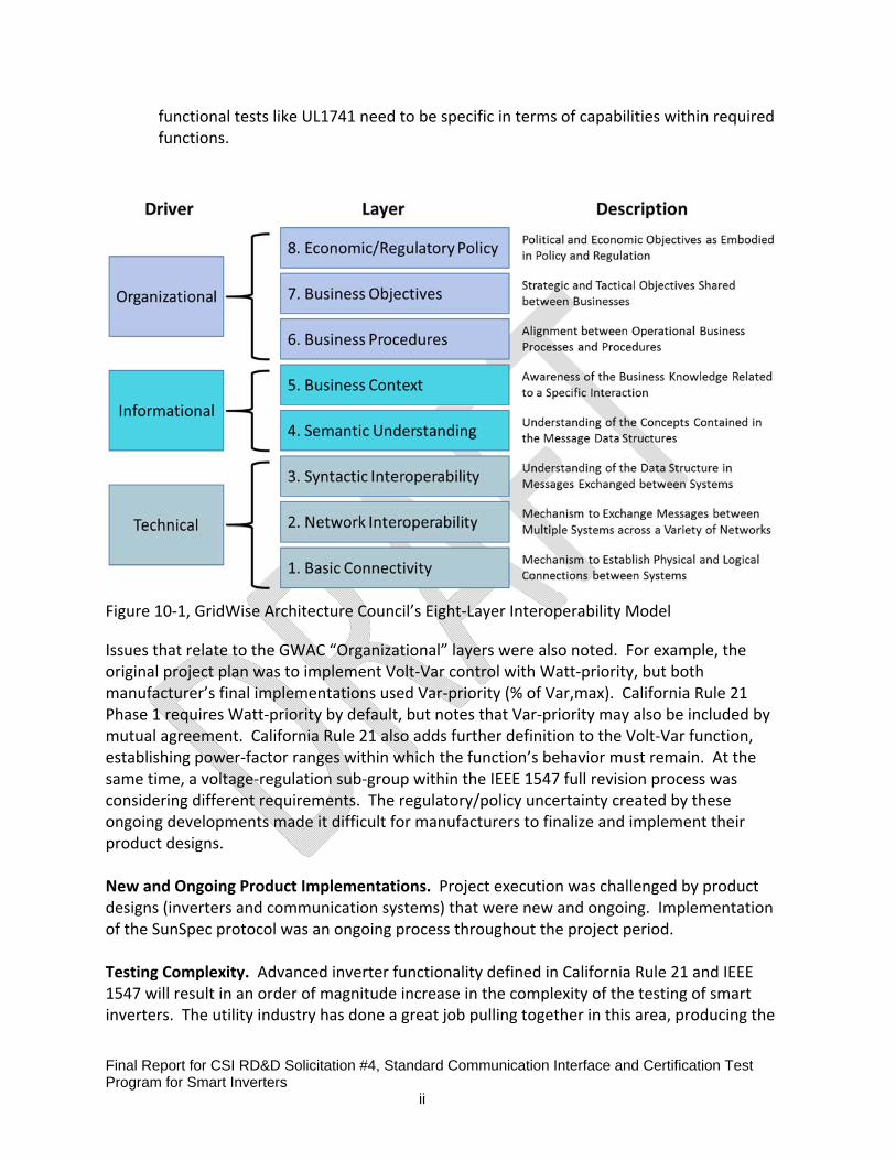
Final Report for CSI RD&D Solicitation #4, Standard Communication Interface and Certification Test Program for Smart Inverters ii
functional tests like UL1741 need to be specific in terms of capabilities within required functions.
Figure 10‐1, GridWise Architecture Council’s Eight‐Layer Interoperability Model
Issues that relate to the GWAC “Organizational” layers were also noted. For example, the original project plan was to implement Volt‐Var control with Watt‐priority, but both manufacturer’s final implementations used Var‐priority (% of Var,max). California Rule 21 Phase 1 requires Watt‐priority by default, but notes that Var‐priority may also be included by mutual agreement. California Rule 21 also adds further definition to the Volt‐Var function, establishing power‐factor ranges within which the function’s behavior must remain. At the same time, a voltage‐regulation sub‐group within the IEEE 1547 full revision process was considering different requirements. The regulatory/policy uncertainty created by these ongoing developments made it difficult for manufacturers to finalize and implement their product designs. New and Ongoing Product Implementations. Project execution was challenged by product designs (inverters and communication systems) that were new and ongoing. Implementation of the SunSpec protocol was an ongoing process throughout the project period. Testing Complexity. Advanced inverter functionality defined in California Rule 21 and IEEE 1547 will result in an order of magnitude increase in the complexity of the testing of smart inverters. The utility industry has done a great job pulling together in this area, producing the

Final Report for CSI RD&D Solicitation #4, Standard Communication Interface and Certification Test Program for Smart Inverters ii
UL 1741SA8 test specification during the project. This specification is becoming the recognized certification process for the smart inverter functions but in‐line with CA Rule 21 Phase 1, does not include any communications testing in the certification at this time. Complete Communication Certification is Needed. Achieving interoperability is difficult, even for a short list of functions and a relatively simple protocol. Communication compliance testing is needed for both inverters and communication modems/modules. A strong supporting testing document and associated processes are needed ‐ Interoperability requires steps beyond basic compliance. The ideal scenario would be formal industry certification end‐end (head‐end to the SunSpec inverter interface) consisting of both conformance and interoperability testing by recognized 3rd party independent test labs. For communication networks that are internally based on open standards, such as the IEEE 2030.5 and OpenADR 2.0b used in this project, communication modules could be provided by multiple sources of supply, so additional certifications are also needed. The OpenADR Alliance has a conformance certification program but it does not include specific smart inverter functionality or interoperability. The USnap Alliance does not currently have a certification program in operation while the SunSpec Alliance conducts a self‐certification program that is only conformance oriented. Neither conduct interoperability testing as part of their certifications. There is a formal industry test specification for IEEE 2030.5 and approved test tools that implement it, but there is not yet a formal industry certification program in place nor does the current specification include interoperability testing, smart inverter specific tests or end‐to‐end testing.
8 1741SA passed initial ballot but with 175 comments. Draft made available to IEEE 1547 for augmentation of 1547.1