Jumal Kejuruteraan 11(1) (1999) 21-34 Performance ... · adalah lebih baik berbanding sistem omni...
14
Jumal Kejuruteraan 11(1) (1999) 21-34 Performance Enhancement of Cellular Topologies Employing Dynamic Cell Sectoring and Base Station Antenna Beam Steering Using Time Division Multiple Access Mahamod Ismail T.L.Doumi J.G.Gardiner ABSTRACT This paper discusses the performance of cellular radio topologies employing dynamic cell sectoring and beam steering. Interference analysis and a teletraffic simulation study based on a TDMA cellular system employing dynamic cell sectoring and base station antenna beam steering technique has been carried out. Results in term of calls dropped, handovers per call, channel utilisation and mean value of CII at the mobiles are compared with those obtained when omni-directional and uni-directional antenna patterns are used in base stations. Simulation results have shown that dynamic cell sectoring system improved teletraffic performances over omni-system but not over sectorisation in some cases. ABSTRAK Kerlas ini membincangkan prestasi topologi radio selular yang menggunakan pengsektoran sel dinamik dan pemacu alur. Analisis gangguan dan kajian simulasi berasaskan sistem selular TDMA yang menggunakan pengsektoran sel dinamik dan antena stesen tapak dengan teknik pemacuan alur telah dijalankan. Hasil kajian yang melibatkan panggilan yang digugurkan, kadar bertukar-tangan bagi setiap panggilan, penggunaan saluran dan nilai purata CII pada stesen bergerak, telah dibandingkan dengan hasil apabila stesen tapak menggunakan corak antena omni-arah dan eka-arah. Hasil simulasi menunjukkan bahawa prestasi teletrafik sistem pengsektoran set dinamik adalah lebih baik berbanding sistem omni tetapi kurang baik berbanding sistem pengsektoran dalam beberapa kes yang tertentu. INTRODUCTION The variety of new services, which will be provided by the Universal Mobile Telecommunication System (UMTS), will be supported by a wider range of cellular topologies than hitherto. In connection less services, for instance, single cell clusters may offer advantages in throughput and capacity in terms over more conventional configurations. The main basis of using different cell topologies is to minimize cellular reuse distance while reducing co- channel interference. Given that the allocated spectrum will be distributed into a smaller area, the system spectral efficiency is increased. Since the implementation of certain topologies is to adapt to certain traffic demands
Transcript of Jumal Kejuruteraan 11(1) (1999) 21-34 Performance ... · adalah lebih baik berbanding sistem omni...

Jumal Kejuruteraan 11(1) (1999) 21-34
Performance Enhancement of Cellular Topologies Employing Dynamic Cell Sectoring and Base
Station Antenna Beam Steering Using Time Division Multiple Access
Mahamod Ismail T.L.Doumi
J.G.Gardiner
ABSTRACT
This paper discusses the performance of cellular radio topologies employing dynamic cell sectoring and beam steering. Interference analysis and a teletraffic simulation study based on a TDMA cellular system employing dynamic cell sectoring and base station antenna beam steering technique has been carried out. Results in term of calls dropped, handovers per call, channel utilisation and mean value of CII at the mobiles are compared with those obtained when omni-directional and uni-directional antenna patterns are used in base stations. Simulation results have shown that dynamic cell sectoring system improved teletraffic performances over omni-system but not over sectorisation in some cases.
ABSTRAK
Kerlas ini membincangkan prestasi topologi radio selular yang menggunakan pengsektoran sel dinamik dan pemacu alur. Analisis gangguan dan kajian simulasi berasaskan sistem selular TDMA yang menggunakan pengsektoran sel dinamik dan antena stesen tapak dengan teknik pemacuan alur telah dijalankan. Hasil kajian yang melibatkan panggilan yang digugurkan, kadar bertukar-tangan bagi setiap panggilan, penggunaan saluran dan nilai purata CII pada stesen bergerak, telah dibandingkan dengan hasil apabila stesen tapak menggunakan corak antena omni-arah dan eka-arah. Hasil simulasi menunjukkan bahawa prestasi teletrafik sistem pengsektoran set dinamik adalah lebih baik berbanding sistem omni tetapi kurang baik berbanding sistem pengsektoran dalam beberapa kes yang tertentu.
INTRODUCTION
The variety of new services, which will be provided by the Universal Mobile Telecommunication System (UMTS), will be supported by a wider range of cellular topologies than hitherto. In connection less services, for instance, single cell clusters may offer advantages in throughput and capacity in terms over more conventional configurations. The main basis of using different cell topologies is to minimize cellular reuse distance while reducing cochannel interference. Given that the allocated spectrum will be distributed into a smaller area, the system spectral efficiency is increased. Since the implementation of certain topologies is to adapt to certain traffic demands
22
or geographical constraints, a wider range of cellular topologies exist, among them: cell splitting, cell sectoring, cell layering and micro-cellular techniques. The topology is usually determine by the base station CBS) configuration and channel assignment strategies.
Hence, base station antennas play important roles in designing cell size and suppressing uLldesired radiation so that effective frequency re-use can be achieved. Base stations employing omni-directional antennas are simpler and cheaper to implement but lead to small gain and offer no discrimination against multi path. On the other hand, base stations employing flxed sector antennas can overcome some of these problems but are not fully optimized according to trafflc conditions. In addition they offer a lower trunking efficiency and probably reduced coverage. Although lowering and tilting the base station antennas give some improvements, new base station architectures that can accommodate the ever increasing capacity while maintaining the required radio quality have to be installed. Such base stations must employ antennas that can dynamically tum their maximum radiation pattern gain in the look direction and to place nulls in the undesired directions. The best choices to fulm the user requirement seems to be adaptive antennas or smart antenna that have been specially developed for military purposes, aerospace industries and satellite communications. Although adaptive antenna is known to be complex and expensive, the continued advancement in electronics will make it feasible to be commercialised and used in cellular mobile communications. Since an adaptive antenna is related to the formation of a multiple beam system, this type of base station configuration is also known as multiple beam antenna system or adaptive beamforming.
New cellular conflgurations that could co-exist within the existing cellular topologies employing adaptive multiple beam base station antennas have been proposed by Telecom Australia (Davies et al. 1988) and then further considered by Swales (Swales et al. 1990), Kwala (Kwala et al. 1993) and Ohgane (Ohgane 1994). The possible use of adaptive antennas in base stations intended for NMT900 and GSM900IDCS1800 has been considered by (Andersson et al. 1994) and (Forssen et al. 1994).
The implementation of an adaptive multiple-beam base station antenna in cellular systems is not far from reality. 'Smart' antenna prototypes which are able to support larger numbers of mobile users in a given area, resulting in an increase in spectrum efficiency over omni-directional systems, have been produced (ERA 1993). A switched-beam smart antenna systems also have been shown to be feasible option for AMP system (Ho 1988). However, much work remains to done before systems are deployed. We are particularly interested on the effect of such scheme on handovers and traffic probabilities and not on direction finding techniques. We called the system as dynamic cell sectoring and base station antenna beam steering since the base station antenna can dynamically reconfigures its 3-dB beamwidth and directs its main beam towards the serving mobiles. Furthermore, the base station system can track the roaming mobiles. A study based on the simulation of a Time Division Multiple Access (TDMA)
cellular system employing dynamic cell sectoring and beam steering technique has therefore been carried out with emphasis on the traffic performance (Mahmod Ismail 1995).

23
INTERFERENCE ANALYSIS
Consider a seven cell cluster cellular system that employs adaptive antenna arrays at the base station to receive and transmit signals from and to Mobile Stations (MSs). The analysis will only consider antenna arrays at the base station, although antenna arrays have been implemented at the MS. Figure lea) shows a desired signal and interference signals from mobiles within and outside the serving base station in the up-link while Figure I (b) shows a similar scenario for downlink interference from adjacent BSs.
Ca)
Cb)
-- Desired signal Interfering signal • Base station
FIGURE 1. Interference in (a) uplink and (b) downlink for dynamic cell sectoring and base station antenna beam steering

24
Now, let us investigate the downlink co-channel interference scenario for two base stations with the notation as shown in Figure 2 in more detail. Assuming base stations BSj and BSk direct their main beams towards their respective serving mobiles. The 3-dB beamwidths of BSj and BSk are 13· and 13k respectively while the distance between base stations BSj and BSk i~ djk•
If the serving mobiles, MSj and MSk, are at (r/9 and (rk'~)' then the carrier-to-interference level at mobile MSj , fj' and at mobile MSk, f k' are given by
f . = r/ .gi(I3I,O)
) X;: ·gk (13,,<p;)
f k = r;Y.g;{I3"O)
X;Y .gk (13k' <p j)
<P i = 1t - [Uj + sin-I( ~ki sin(uk ))]
<Pk = 1t - [Uk + sin-I( ~k sin(uJ)]
and y is the propagation constant g{) is the gain of beam j gk(.) is the gain of beam k
~1<::-------->l3>t BS k
FIGURE 2. Interference analysis in downlink for two base station
(1)
(2)
(3)
(4)
(5)
(6)
In order to maintain communications, carrier-to-interference levels at both MSs must be greater than a threshold, fth' such that, fj > fth' and f k > f th . If one of the mobile, e.g. MSk, is already been serviced by a base

25
station, e.g. BSk, another mobile, e.g. MSj , can only be serviced by a different base station, e.g. BSj and re-using the same channel when it is within certain location from both BSs.
Besides the analytical representation as above, a simulation study has also been carried out (Abdalla et al. 1996). A short program was written in MATLAB© to investigate the above scenarios. The antenna pattern is modelled as a sinc2 function. The overall antenna gain is also affected by the 3-dB beamwidth of the antenna. The effect of log-normal shadowing is also studied. Carrier-to-interference levels are measured at various values of (ri , <Xj ) and their cumulative distributions are then plotted. Throughout the simulation, various parameters that influence the cochannel interference had been analysed. These included the interfering base station antenna 3-dB beamwidth size and its main beam orientation towards serving base station, the distance between serving and interfering base stations and contribution of a log-normal shadowing. Furthermore, azimuthal angle of serving mobile with respect to main beam orientation of interfering base station, will determine whether the mobile is in the null or side lobes of interfering base station antenna. If it is so, the mobile will achieve higher value of carrier-to-interference.
TELETRAFFIC SIMULATION
The simulation environment represents a sub-urban area served by a number of base stations arranged in a symmetrical fashion. The following assumptions have been made:
1. The call traffic is derived from Poisson-distributed arrivals and exponentially distributed call duration's. 2. Mobile spatial locations at call set-up are uniformly distributed throughout the simulated area with mobiles moving randomly in 8 possible directions. The speed and direction of every mobile are kept constant throughout its call duration. The former is generated from a uniform distribution. 3. The propagation channel is characterised by a distance dependent loss and log-normal shadowing. 4. A handover is initiated as soon as the quality of the signal falls below a carrier-to-interference threshold. However, handover re-attempts are allowed before any call is dropped. 5. Dynamic Channel Assignment (DCA) is used throughout. The signal selection is based on the best carrier-to-interference plus noise ratio. 6. Each base station has only one active transceiver during each time-slot. 7. The base station antenna pattern of every beam is modelled by a sinc2
function with a variable beamwidth. Mobiles' antennas are omni-directional. 8. The location, or rather the direction of arrival (DOA), of the mobile is known to every base station.
Table 1 summarises the various parameters that have been used throughout the simulation. Call statistics are gathered at the end of the simulation. The performance is then based on the percentage of dropped

26
calls, rejected calls out of the total number of simulated calls and the number of handovers (inter and intra handover) per call. The simulation is re-run for different traffic densities, beam formation and antennas parameters.
TABLE 1. Simulation parameters
Number of Base-Stations
Base-station transmitted power
C/(I+N)threshold
Receiver Sensitivity (Noise Floor)
Log-Normal Shadowing
No. of Frequency Carriers
Total SlotlFrame (TDMA)
Mean Call Duration
Handover re-attempts
Mobile Mean Speed
16
27 - 40 dBm
9 dB
-105 dBm
8 dB
12
8
120 s
10 x 1.67 s
15 mls
DYNAMIC SECTORING BEAM FORMATION ALGORITHMS
The beam formation at every base station is based on the mobiles' DOAs. Figure 3(a) shows the actual parameters used in the algorithm. Given the jth base station and two mobiles, say the ith and the kth, the angles of arrival are denoted a ~ij and (X.kj respectively while the separation angle between the mobiles is r {}. By setting a minimum separation angle between adjacent mobiles, say y, we are then in a position to narrow or widen antenna beamwidths after all directions of arrivals have been sorted. Figure 3(b) shows an example of beam formation where
(~j - (X.lj) < y and «(X.3j- (X.2j) < y
(u4j - (X.3j) > y and «(X.5j- (X.4j) < y
(U6j - U5j) > y,
(~j - (X.6j) > y and
(u8j - (X.7j) > y
Henceforth, beam number 1 and 2 respectively will cater for a group of three and two mobiles, while beams numbers 3,4 and 5 will cater each for a single mobile. The beams sizes are given by (uij-(X.pj + y) where i and p represent the first and the last mobiles in the same beam respectively. When a new mobile arrives such that,
(~j - U1j) < Y and (U3j- ~j) < y,
(U4j - (X.3j) > y and «(X.5j- (X.4j) < Y
«(X.6j - (X.5j) > y, «(X.newj - u 6j) < y and (~r u newj) < y and
(u8j - U7j) > y

27
then the new formation of beams is as shown in Figure 3(c). It can be seen that the number of beams is teduced from five to four and there is only a single beam serving lone mobile instead of three.
(a)
Bcunl Beun2 llearn> • Bcun4 .------ -- -- 1
I
, EI
, 1:1 1:1 1:1 1:1 1:1 1:1 1:1 ~
a Ij a lj IX 3j IX 4j IX ~j a 6j IX 7j IX 8j IX 9j a .. I)
Direction of arrival
(b)
!learn I n""m2 Beam3 Dum4 - ----- -- -- 1 -- - -------1 I I
, 1
, I ! n n n a Ij a 2j a 3j a 4j a Sj a 6j a ncwj a 7j a 8j a 9j a ij
Direction of arrival (c)
FIGURE 3. (a) Actual beam formation algorithm parameters and (b) Examples of beam formation (c) Beam reformation to accomodate a new call
Now consider two other different algorithms that are based on maximum numbers of mobiles in a beam and minimum separation between adjacent beams. For the mobiles DOA as shown in Figure 3(c), if the maximum number of mobiles in a beam is two and adjacent beams must be separated by at least the minimum size of a beam ~ = y, then new beam formations are shown in Figures 4(a) and (b) respectively. However, in the second algorithm (a6f a5j) > 2y is considered.
It is clearly shown that two extra beams are formed as the numbers of mobiles in a beam were limited to two. Furthermore, adjacent beams were prone to overlap. If the size of a beam is limited to a certain beamwidth, similar results would occur. On the contrary, by limiting the spacing between adjacent beams to y, the numbers of beams were reduced to two.
In the real system implementation, a maximum beam size for each zones usually must be defmed. The minimum size of each beam will then determine the number of beams in each zone. Each beam can also be assumed to be separated

28
!learn I !leam2 Beam3 Bcam4 BeamS 8eam6 - - - - - - T-r - -I -- - -I
I I 0
I I
~ - - - - - r, - -. o 0
I I I
I I I I I I I I o I
0 I I
0 8 ! n n n I
alj a 2j a 3j a 4j a Sj
I I I ,n .,..,. I
'n l " ) a 9j a ij a 6j a newj a 7j
Direction of arriva
(a) BeIIml Beam2 ----------------, I
1---------------, o !
I I
'n n" .M nR n° n ) a 9j a ij a Ij a 2j a 3j a 4j a Sj a 6j a newj a 7j
Direction of arriva (b)
FIGURE 4. Beams formation based on (a) maximum numbers of mobiles in a beam and (b) minimum seperation between adjacent beams
from the others at least by certain beamwidth. A trade-off between the beamwidth (and hence the maximum number of beams per users) and the side lobes level (and hence the intetference suppression experienced at the users) is suggested.
RESULTS AND DISCUSSION
Performance of Dynamic Cell Sectoring against Omni-directional and Unidirectional Antenna Patterns
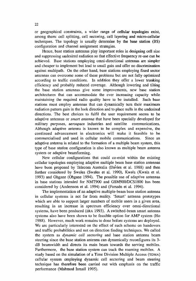
A comparison was made by assuming a uni-directional system as a type of base station antenna pattern. Three types of antenna sectorisations have been used to illuminate full horizontal coverage: 3 x 120°, 6 x 60° and 12 x 30°. The main beams of 60° sectors were pointed towards 30°, 90°, 150°,210°, 270° and 300° while the main beams of 120° sectors were pointed towards 60°, 180° and 300°C. Similarly the main beams of30° were pointed towards 15°,45°,75°, 105°C, 135°, 165°, 195°, 225°, 255°, 285°, 315° and 345°. For a dynamic cell sectoring and base station antenna beam steering system, an "idle" base station, i.e. not serving any mobiles, is assumed to use omni-directional antenna pattern. The minimum separation angle between adjacent mobiles serving the base station and the antenna minimum 3-dB beamwidth are assumed to be equal i.e. a = y = 6°.
From the simulation results as shown in Figures 5(a), 5(b) and 5(c), it is clear that the dynamic cell sectoring approach gives some significant performance improvement against the omni system in terms of fewer dropped calls (approximately 15% better) and fewer handovers per call. As for the blocking performance, the dynamic cell sectoring method performs better than omni-systems approximately by 3%, below 8 Erlangs for this specific case study. However, beyond this figure, the omni-system performs better than dynamic cell sectoring system.
- r- -,... - - -,- , - -, - ,-_ , __ 1 ____ 1 __ , _ J _ .J _
I I 1 I I 1 - t- - t- - - -1- -t - -t - -t, ,
-T-,.-r-,.._J._.1..L_L _
I , I 1 -.,.-t'-t--":
I ,
-'--I- ----~-~ ::::::: :::v:='= ~- ... -, , , , -1- -,-_ L. _'-
6--6 3al11O·AudIildaf __ OMI
_ L _, ____ ,_ J _ J _ J_ , , , -t"'" -r- - - -1- -.- '"1-"1-
• I 'I' I -.- -,- - - -,- -.- i - .-
,. 'I I I - ,- -,- - - -,- -, ~ i - "1-_ ~ _ L. _ __ 1_ ..... _ ..I _ ..,_
I I 1 I
(a)
r-r.L._L. _
10.0
~r-----~------------r-----------~-----------'
J _~_L __ ~_~_~_~_
r r r r I 1
~~-I'-'-I'-~-_-;-I-~-'---TI-_-T'--r~~'-;-~~T7~~
i "
1.5 11.0 7.1
(b)
-:- r'-_--'.-=-~-'-....:..--....:....--'.IooJeI-''-:-~-I- ~ - ~ - ~ ~_ .....--.. ,,,,.,,,,,,,,, I 1 I
.......-..................... I __ .. t" __ , _0n00I -: - '-,-,...---;--,--.--.,.--...,--....,..-/
I
1 .0
(e)
- ... - .... - ... -1--
10.0
I I r I
_.L_L_I_~_ I , I
1.6 10.0
FIGURE 5. (a) Dropping Percentage (b) Blocking Percentage and (c) Handover/call for different traffic/cell for dynamic cell sectoring. omni-directional and uni~directional BS antenna patterns [~ = y = 6°]
29

30
The dynanlic cell sectoring approach gives some significant perfonnance improvement in comparison with sectorisation but only in tenns of fewer dropped calls when the traffic/cell is above 5 Erlangs (1 % to 8% improvement). Fewer handovers per call were gathered by the dynanlic cell sectoring against 3 x 120° sectorisation but not against 6 x 60° and 12 x 30° sectorisations. As for blocking perfonnance, the dynanlic cell sectoring perfonned better than 6 x 60° and 12 x 30° sectorisation but not against 3 x 120° sectorisation.
Carrier-to-Interference Ratio Distributions Spectral efficiencies of cellular systems are influenced by the carrier-tointerference ratio distributions at the mobiles . Furthennore, the gain of the beam in a certain azimuthal direction and thus carrier-to-interference ratios, are functions of the antenna minimum 3-dB beamwidth and the azimuthal direction deviation from the antenna main lobes. Carrier-to-interference ratio distributions at the mobiles for different antenna minimum 3-dB beamwidths and direction-of-arrival errors were examined (Mahmod Ismail, et al. 1994). Better perfonnances as expected are achieved when the minumum 3-dB beamwidhth is reduced. Although DOA errors yet result in better CII values (at least by 5 dB) than with omni-directional antennas, there is no apparent, or significant, degradation of the CII distribution.
Channel Utilisation Carrier-to-interference ratios were measured at selected channels for certain duration of time. Three channels have been selected: channell, channel 48 and channel 96. The selection represented channel in the middle and channels at both ends. The cumulative distributions of carrier-to-interference ratio at different channels were then plotted. The traffic per cell was maintained at 7 Erlangs. Higher CII values can be obtained when dynamic cell sectoring system is used as compared to either when ornni-directional or 6 x 60° sectoring are employed. The median values of a dynamic cell sectoring were respectively improved by at least 10 dB and 1 dB compared to omni-directional and 6 x 60° sectoring.
Effect on Dynamic Channel Assignments Two types of carrier-to-interference selection criteria were studied (Mahmod Ismail et al. 1995a). The selection criteria was based on best CII and least good CII. In the fonner, a channel which gives best CII was selected while in the latter a good channel i.e CII ~ CIITH' which has lowest CII was selected. Figure 6(a) show respectively plots of maximum channel re-use for best CII and lowest good CII selection criteria.
From the plots, it is clear that channel assignment method based on least good CII perfonns much better than channel assignment method based on best CII. The improvement is denoted by increasing number of channel reuses. The last two carriers also were not used which indicate that 10 carriers can be used in the simulation.
Furthennore, the perfonnance of channel assignment based on best CII seems better than channel assignment based on lowest good CII in tenns of lower dropping percentage (up to 8%) and fewer handovers per call (up to 10 handovers/caU). However, in terms of blocking percentage, channel assignment based on lowest good C/I perfonns much better than channel assignment based on best CII particularly when traffic/cell is greater than 5 Erlangs.

4
3
2
o
Max. no. of cbanncl ~
1 2 3 4 5 , 7 I 9 10 11 12
Carrier DO., C
(a)
Max. no. of ehInneI re-UIC
12] 4" ,.91011 12
Carrier DO., C
(b)
23
1
7' " 4 Slot no., s
FIGURE 6. Carrier-to-interference selection based on (a) best CII and (b) least good CII
Effect of Beam Formation Updating Time
31
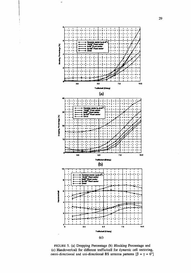
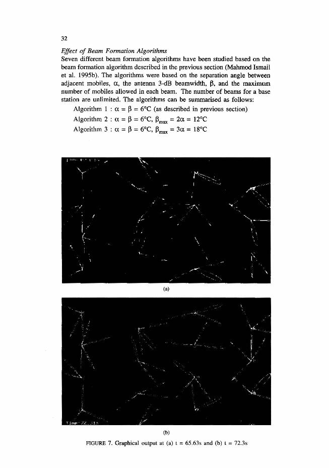
The whole antenna patterns of a single base station, i.e. its beam orientations and their widths, were updated at regular time intervals. By doing so, the mobile will be tracked in azimuthal direction by the beam. Graphical outputs of a simulation state at times t=65.63s and t=72.31s are respectively shown in Figures 7(a) and 7(b).
During that elapsed time, the beam patterns of seven base stations have been updated. The number of blocked calls is also found not greatly affected by how fast the beam is being updated. A similar conclusion can be drawn for the number of dropped calls although the number of handovers per call has increased by 10% when updating time is being doubled.
32
Effect of Beam Formation Algorithms Seven different beam formation algorithms have been studied based on the beam formation algorithm described in the previous section (Mahmod Ismail et a1. 1995b). The algorithms were based on the separation angle between adjacent mobiles, a, the antenna 3-dB beamwidth, ~, and the maximum number of mobiles allowed in each beam. The number of beams for a base station are unlimited. The algorithms can be summarised as follows:
"
Algorithm 1 : a = ~ = 6°e (as described in previous section)
Algorithm 2 : a = ~ = 6°e, ~max = 2a = l20e
Algorithm 3 : a = ~ = 6°e, ~max = 3a = 18°e
I-- I .... ~
\y "
... r----..... ~---....
"-~-
..... -~ -'. .
.-.~~:!\ ..... -/
f .- " ,.'" l,~-
I '\
( \ '. , ,
", [< ;~ /--
(a)
(b)
FIGURE 7. Graphical output at (a) t = 65 .63s and (b) t = 72.3s
\.

33
Algorithm 4: a = ~ = 6°, Maximum number of mobiles in each beam =1
Algorithm 5 : a = ~ = 6°, Maximum number of mobiles in each beam = 3
Algorithm 6: a = ~ = 6°, Maximum number of mobiles in each beam = 5
Algorithm 7 : ~ = 6°C (separation between adjacent beams ~ ~)
The teletraffic performance of a dynamic cell sectoring for various beam updating algorithms at traffic per cell of 7 Erlangs are tabulated in Table 2.
TABLE 2. Blocking percentages, dropping percentages and handovers per call for different beam updating algorithm at traffic/cell ::; 7 Erlangs
Blocking Percentage Dropping Percentage Handovers/call (%) (%)
Algorithm 1 1.47 2.38 6
Algorithm 2 0.73 8.79 6
Algorithm 3 0.87 8.98 6
Algorithm 4 1.11 8.24 4
Algorithm 5 0.65 11.75 10
Algorithm 6 0.35 14.53 18
Algorithm 7 1.54 5.76 2
From the table, it is clear that as wider antenna 3-dB beam width were allowed, the blocking percentages and dropping percentages were increased as shown by algorithm 2 and algorithm 3. By allowing more mobiles in a beam, the dropping percentages and number of handovers per call were increased. Conversely, the blocking percentages were decreased. The minimum number of handovers per call were achieved when the adjacent beams were separated at least by the size of antenna 3-dB beamwidth as shown by algorithm 7.
CONCLUSION
The teletraffic performance of cellular topologies employing dynamic cell sectoring and beam steering in a TDMA mobile radio system employing a DCA strategy has been studied. Simulation results have shown that the performance of a dynamic cell sectoring is better than an omni-directional base station system. This was shown by fewer dropped calls, fewer handovers per call, better channel utilisation and better mean value of CII at the mobiles. Further improvements were gained when channel assignment method based on lowest good CII were used. They have also shown that even a coarse knowledge of the direction of arrival, for direction finding purposes, may be sufficient to provide an enhancement to the provision of services, when compared with the omni system.

34
REFERENCES
Abdalla, A.G.E. M.lsmail & A.EMohd Zaino Cost optimization softwares for a mobile radio system. Proc. IEEE Singapore International Conference on Communication Systems (ICCS) !International Workshop on Intelligent Signal Processing & Communication Systems (ISPACS), 28 -30 Nov 1996, Vol. 113, 10.2.1 - 10.2.5.
ERA Technology News. 1993 - Winter, pp.l. H.Andersson, M.Landing, A.Rydberg & T.Oberg. 1994. An adaptive antenna for the
NMT 900 mobile telephony system. Proc. 43rd IEEE Vehicular Technology Conf., pp. 610-614.
Mahmod. Ismail, T.L. Doumi & lG. Gardiner. 1995a. Adaptive radio coverage in a mobile cellular system. Proc. 2nd IEEE Malaysia International Conference on Communications 1995, Langkawi. pp. 5.5.1-5.5.5.
Mahmod. Ismail, T.L. Doumi & J.G. Gardiner, 1995b. Performance of a dynamic cell sectoring and base station antenna beam steering for a mobile cellular syste. Proc. IEEE International Conference on Jakarta Asia Pacific Communication Conference, Jakarta p. 8.1.1 - 8.1.5.
Mahmod.Ismail, 1995. Cellular topologies for personal communication. Ph.D Thesis, University of Bradford.
Ho, M.J. G.L.Stuber & M.Austin. 1998. Performance of switched-beam smart antennas for cellular radio systems. IEEE Transaction on Vehicular Technology 47 (1): 10 - 19.
Kwala, P. A.U.H.Sheikh. 1993. Adaptive multiple-beam array' for wireless communications, lEE Int. Con/. on Antennas and Propagation ICAP93: 971-974.
Swales, S.c. M.A. Beach & DJ. Edwards. 1990. The performance enhancement of multibeam adaptive base station antennas for cellular land mobile radio systems, IEEE Transaction on Vehicular Technology 39(1): 56 - 67.
Ohgane. T. 1994. Spectral Efficiency Evaluation of Adaptive Array base Station for Land Mobile Cellular Systems. Proc. 43rd IEEE Vehicular Technology Conf., pp. 1470-1474.
Forssen, U. J.Karisson, B.Johannisson, M.Almgren, ELotse & EKronestedt. 1994. Adaptive antenna arrays for GSM900IDCSI800. Proc. 43rd IEEE Vehicular Technology Con! pp. 605-609.
Davies, W.S . R.J.Lang & E.Vinnal. 1988. Proposed advanced base station antennas for future cellular mobile radio systems. Australian Telecommunications Research 22(1): 53-60.
Mahmod Ismail Department of Electrical, Electronic and System Engineering Faculty of Engineering Universiti Kebangsaan Malaysia 43600 UKM Bangi Selangor D.E. Malaysia
T.L. Doumi & J.G. Gardiner Telecomunication Research Group Department of Engineering and Electrical Universiti Kebangsaan Malaysia 43600 UKM Bangi Selangor D.E. Malaysia