JP - PowerBox Systems · To ensure, that the Mercury SRS can work with the RC system, you have to...
3
is the CARF J-10: too many channels for a standard receiver, fast and strong servos with large deflexions for the thrust vector control and the 3D flight needs Gyro support. Of course, the J-10 can fly with only one battery and one receiver. But, due to bad experience, I fly my jets only with receiver and battery redundancy. The integrated GPS telemetry functions such as height, speed, distance, flown route, coordinates, etc., are very interest- ing. As in the Royal SRS, all data is passed through, so the GPS sensor is available for the speed-dependant adjustment of the sensitivity (Gain) of the iGyro and teleme- try. It reduces the amount of servos and cables, making the installation easier. Before installing and launching the Mercury SRS, it’s worth taking a look into the very compact manual, which can be also downloaded from the PowerBox website. If you have questions, a visit of the PowerBox expert forum at forum.powerbox-systems.com might help. Here, you will find many tips and tricks regarding all PowerBox products and your questions will be answered quickly. It’s recommended to test-install the compo- nents and test servos, in order to learn about their functions. Before installing into the jet, you should reset the Mercury, which makes the configuration much faster. To ensure a trouble-free function of the Mercury, it should be screwed right-angled to the main axis on a firm surface in the model. The position will be recognised automatically. The handling of the Mercury SRS follows the proven tradition. The supplied sensor switch serves as on and off switch for both batteries. The box can be config- ured with the three buttons in combina- tion with the external display. In order to activate the Mercury, the switch, the display, two serial receivers (four satellites in the Spektrum) and the GPS II sensor are in- stalled. Two batteries with Multiplex plug are needed for the power supply. The correct battery polarity is ab- solutely necessary, a wrong polarity would destroy the voltage regulators! The start display shows the battery volt- age, the receiver status, the GPS anten- na, the position of the flight mode switch, the operating time and the output voltage for receiver and servos. All infos, except for the timer, can be shown on telemetry displays of almost all com- mon RC systems. The Mercury displays are in English, special terms in the manu- al are written in German. To ensure, that the Mercury SRS can work with the RC system, you have to choose the RC system in the menu item “General Settings”. The receivers have to be set to serial transmission, in order to communicate with the Mercury. If two re- ceivers are plugged in, the Mercury will choose one during the switch-on and will switch onto the other within seconds, if having receiving problems. In order to improve the receiving situation, I keep my receivers wide apart from each other. In jets I place one receiver in the cockpit area, one antenna in flight direction, another one across. The second receiver is placed in the mostly hollow vertical sta- biliser, one antenna vertical, the other one horizontal. That’s how I cover all receiving directions. In dependence of the applied servos and batteries, the next steps are setting up the frame rate, the battery type and the desired output voltage. The Mercury can be set up to LiIon, LiPo, LiFePo or NiMh. If the wrong battery is set up, the switch will still work, only the graphic bar display won’t be accurate. The assistants The already known assistants have been developed consequently, in order to make the set-up as easy as possible, assuming, there is a prepared RC trans- mitter, meaning, all functions and encoders are configured and verified with JET POWER 6/2016 25 25 Measures 93 x 67 x 19 mm Weight 85 g Weight sensor switch 15g Weight Display 15 g Operating voltage 4,0 – 9,0 V Power supply 2s LiPo / LiIon / LiFePo, 5s NiCd / NiMH Power consumption operation 99 mA (mit OLED) Power consumption standby 3 µA Current carrying capacity peak 2 x 20 A Dropout current 0,3 V Output voltage 5,9 or 7,4 V stabilised Signal input serial Supported RS systems Jeti, Futaba, Spektrum, HoTT, M-Link, JR Propo Receiver redundancy SRS Channels 15 (18) Servo outputs 15 Resolution servo impulse 0,5 µs Impulse repetition rate 12, 15, 18, 21 ms Gyroscope system iGyro Gyro controlling Heading and normal mode Gyro-sensor type MEMS Number sensor axis 6 Supported telemetry Jeti, Futaba, Spektrum, HoTT, M-Link, JR Propo Price 499,- € Manufacturer PowerBox Systems www.powerbox-systems.com In order to learn about the functioning of the Mercury, it was equipped with two serial receivers and a GPS sensor. The menu screen is clear and uncluttered. TECHNICAL DATA JP The Mercury has a lot of functions: 15 servo outputs, an iGyro with GPS regulation, two serial receiver inputs, two battery inputs with two redundant regula- tion systems and each with 20 A peak current, the output voltage can be set to stabilised 5,9 or 7,4 V, extensive telemetry functions, door sequencer, ser- vo matching and a lot more. Furthermore, the Mercury works with almost all current RC systems and can decode 18 channels serially. The proven iGyro unites the experiences of all the versions iGyro 3e, iGyro SRS and Royal SRS. The external OLED display has a similar size to those of the integrated Cockpit/Competition series. The Mercury fits into all jets with 15 servo outputs and the currents passing through the receiver. Prime example for the successful application of the Mercury 24 24 JET POWER 6/2016 MULTI-FUNCTIONAL ERICH BÄCKER JP www.jetpower-magazin.com Having switched to the Jeti DC-16 transmitter, Erich Bäcker went on a hunt for new receivers, a gyroscope and a power supply for his CARF J-10. So, the Mercury SRS from PowerBox Systems, a redundant system with integrated gyro and serial receiver inputs, came at the exact right moment. One could say, that the Mercury is a bridge between the high-end Royal SRS and the smaller Cockpit/Competition. The small POWER MANAGER PowerBox Systems Mercury SRS The delivery scope of the Mercury SRS from Power- Box Systems with GPS II sensor. The start screen of the Mercury.
Transcript of JP - PowerBox Systems · To ensure, that the Mercury SRS can work with the RC system, you have to...

is the CARF J-10: too many channels for astandard receiver, fast and strong servoswith large deflexions for the thrust vectorcontrol and the 3D flight needs Gyrosupport. Of course, the J-10 can fly withonly one battery and one receiver. But,due to bad experience, I fly my jets onlywith receiver and battery redundancy.
The integrated GPS telemetry functionssuch as height, speed, distance, flownroute, coordinates, etc., are very interest-ing. As in the Royal SRS, all data is passedthrough, so the GPS sensor is available forthe speed-dependant adjustment of thesensitivity (Gain) of the iGyro and teleme-try. It reduces the amount of servos andcables, making the installation easier.
Before installing and launching theMercury SRS, it’s worth taking a look intothe very compact manual, which can bealso downloaded from the PowerBoxwebsite. If you have questions, a visit ofthe PowerBox expert forum atforum.powerbox-systems.com might help.Here, you will find many tips and tricksregarding all PowerBox products and yourquestions will be answered quickly. It’srecommended to test-install the compo-nents and test servos, in order to learnabout their functions. Before installinginto the jet, you should reset the Mercury,which makes the configuration muchfaster. To ensure a trouble-free function ofthe Mercury, it should be screwedright-angled to the main axis on a firmsurface in the model. The position will berecognised automatically.
The handling of the Mercury SRSfollows the proven tradition. The suppliedsensor switch serves as on and off switchfor both batteries. The box can be config-
ured with the threebuttons in combina-tion with the externaldisplay. In order toactivate the Mercury,the switch, the display,two serial receivers(four satellites in theSpektrum) and theGPS II sensor are in-stalled. Two batterieswith Multiplex plug areneeded for the powersupply. The correctbattery polarity is ab-solutely necessary, awrong polarity woulddestroy the voltageregulators!
The start displayshows the battery volt-age, the receiverstatus, the GPS anten-na, the position of theflight mode switch, theoperating time and the
output voltage for receiver and servos. Allinfos, except for the timer, can be shownon telemetry displays of almost all com-mon RC systems. The Mercury displaysare in English, special terms in the manu-al are written in German.
To ensure, that the Mercury SRS canwork with the RC system, you have tochoose the RC system in the menu item“General Settings”. The receivers have tobe set to serial transmission, in order tocommunicate with the Mercury. If two re-ceivers are plugged in, the Mercury willchoose one during the switch-on and willswitch onto the other within seconds,if having receiving problems. In order toimprove the receiving situation, I keep myreceivers wide apart from each other. Injets I place one receiver in the cockpitarea, one antenna in flight direction,another one across. The second receiveris placed in the mostly hollow vertical sta-biliser, one antenna vertical, the other onehorizontal. That’s how I cover all receivingdirections.
In dependence of the applied servosand batteries, the next steps are setting upthe frame rate, the battery type and thedesired output voltage.
The Mercury can be set up to LiIon,LiPo, LiFePo or NiMh. If the wrong batteryis set up, the switch will still work, only thegraphic bar display won’t be accurate.
The assistantsThe already known assistants have
been developed consequently, in order tomake the set-up as easy as possible,assuming, there is a prepared RC trans-mitter, meaning, all functions andencoders are configured and verified with
JETPOWER 6/2016 2525
Measures 93 x 67 x 19 mm
Weight 85 g
Weight sensor switch 15g
Weight Display 15 g
Operating voltage 4,0 – 9,0 V
Power supply 2s LiPo / LiIon /LiFePo, 5s NiCd /NiMH
Power consumptionoperation 99 mA (mit OLED)
Power consumptionstandby 3 µA
Current carryingcapacity peak 2 x 20 A
Dropout current 0,3 V
Output voltage 5,9 or7,4 V stabilised
Signal input serial
Supported RS systems Jeti, Futaba,Spektrum, HoTT,M-Link, JR Propo
Receiver redundancy SRS
Channels 15 (18)
Servo outputs 15
Resolutionservo impulse 0,5 µs
Impulse repetition rate 12, 15, 18, 21 ms
Gyroscope system iGyro
Gyro controlling Heading andnormal mode
Gyro-sensor type MEMS
Number sensor axis 6
Supported telemetry Jeti, Futaba,Spektrum, HoTT,M-Link, JR Propo
Price 499,- €
Manufacturer PowerBoxSystems
www.powerbox-systems.com
In order to learn about the functioning of the Mercury, it was equippedwith two serial receivers and a GPS sensor.
The menu screen is clear and uncluttered.
TECHNICAL DATAJP
The Mercury has a lot of functions:15 servo outputs, an iGyro with GPSregulation, two serial receiver inputs, twobattery inputs with two redundant regula-tion systems and each with 20 A peakcurrent, the output voltage can be setto stabilised 5,9 or 7,4 V, extensive
telemetry functions, door sequencer, ser-vo matching and a lot more. Furthermore,the Mercury works with almost all currentRC systems and can decode 18 channelsserially. The proven iGyro unites theexperiences of all the versions iGyro 3e,iGyro SRS and Royal SRS. The external
OLED display has a similar size to thoseof the integrated Cockpit/Competitionseries.
The Mercury fits into all jets with 15servo outputs and the currents passingthrough the receiver. Prime example forthe successful application of the Mercury
2424 JETPOWER 6/2016
MULTI-FUNCTIONAL ERICH BÄCKERJPwww.jetpower-magazin.com
Having switched to the Jeti DC-16 transmitter,Erich Bäcker went on a hunt for new receivers,a gyroscope and a power supply for hisCARF J-10. So, the Mercury SRS fromPowerBox Systems, a redundant system withintegrated gyro and serial receiver inputs,came at the exact right moment. One couldsay, that the Mercury is a bridge betweenthe high-end Royal SRS and the smallerCockpit/Competition.
The smallPOWER
MANAGERPowerBox Systems Mercury SRS
The delivery scope of the Mercury SRS from Power-Box Systems with GPS II sensor.
The start screen of the Mercury.
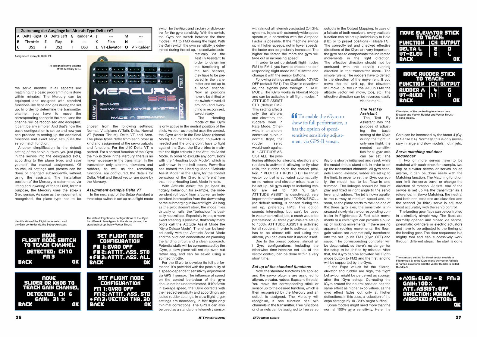
with almost all telemetry-adjusted 2,4 GHzsystems. In jets with extremely wide speedspectrum, a correction with the AirspeedFactor is possible. If the machine swingsup in higher speeds, not in lower speeds,the factor can be gradually increased. Thehigher the factor, the more the gyro willfade out in increasing speed.
In order to set up default flight modesFM1 to FM 4, you have to choose the cor-responding flight mode via FM switch andchange it with the sensor buttons.
Following settings are available: *GYROOFF (default FM1) The iGyro is deactivat-ed, the signals pass through. * RATEMODE The iGyro works in Normal Modeand can be activated in all flight modes. *ATTITUDE ASSISTSTD (default FM2)This setting affectsonly the aileronsand elevators, therudders work inRate Mode. Other-wise, in an aileron-controlled curve innormal flight, therudder servowould work againstit. * ATTITUDE AS-SIST ALL The posi-tioning attitude for ailerons, elevators andrudders is activated, allowing to fly slowrolls, the rudder holds the correct posi-tion. * VECTOR THRUST 3 D The thrustvector control is activated automatically,so no rudder and elevator mixes have tobe set up. All gyro outputs including vec-tor are set to 100 % gain,ATTITUDE ASSIST is deactivated, veryimportant for vector jets. * TORQUE ROLL(no default setting, is chosen during theset up, preferably FM3) This optionsounds interesting, but can’t be usedin vector-controlled jets, a crash would bepredestined. All three gyro axis are set upto 100%, ATTITUDE ASSIST is activatedfor all rudders. In order to activate, the jethas to be almost still, and using theaileron, you can even turn it around itself.
Due to the preset options, almost alli Gyro configurations, including theotherwise time-intensive set up of thevector control, can be done within a veryshort time.
Set up of the standard functionsNow, the standard functions are applied
and the servo plug-ins are assigned toaileron, elevator, rudder, flaps and throttle.You move the corresponding stick orsensor up to the desired function, which isthen recognised by the Mercury and anoutput is assigned. The Mercury willrecognise, if one function has twochannels in the transmitter. Free functionsor channels can be assigned to free servo
outputs in the Output Mapping. In case ofa failsafe of both receivers, every availablefunction can be set up individually to Hold(HD) or to preset positions (Failsafe FS).The correctly set and checked effectivedirections of the iGyro are very important,the gyro has to compensate the indirectedmovements in the right direction.The effective direction should not beconfused with the servo’s runningdirection in the transmitter menu. Thesimple rule is: The rudders have to deflectin the direction of the movement. If youmove the tail unit up, the elevatorswill move up, too (in the J-10 in FM3 thealtitude vector will move, too), etc. Theeffective direction can be reversed easily
via the menu.
The Test FlyAssistant
The Test FlyAssistant has thepurpose of adjust-ing the basicsetting of the iGyroduring the flight. Inonly one flight, theneeded sensitivi-ties for all gyro axiscan be set. The
iGyro is shortly initialised and reset, whilethe model should stand still. In order to setup the transmitter channels, all gyro chan-nels aileron, elevator, rudder are set up tothe limit. In order to set the iGyro correct-ly, the model has to be flown-in andtrimmed. The linkages should be free ofplay and fixed in right angle to the servolever and rudders. The jet is flown parallelto the runway at medium speed and, assoon, as the plane starts to rock on one ofthe three gyro axis, the sensitivity is in-creased slowly via the corresponding con-troller in Flightmode 2. Fast stick move-ments or a knife flight can provoke a buildup of rocking movements. If there are noapparent rocking movements, the flowngain values are automatically transferredinto the set up via FM1 (Gyro OFF) andsaved. The corresponding controller willbe deactivated, so there’s no danger forthe setup to be shifted by mistake. Afterthat, the iGyro can be activated via Flight-mode button to FM2 and the first landingwill be supported by the Gyro.
If the Expo values for the aileron,elevator and rudder are high, the flightbehaviour might be perceived as spongy,after the iGyro set-up. Correcting theiGyro around the neutral position has thesame effect as higher expo values, as thegyro effect fades out only at higherdeflections. In this case, a reduction of theexpo settings by 10 - 20% might suffice.
Some models might need more than thenormal 100% gyro sensitivity. Here, the
Gain can be increased by the factor 4 (Gy-ro Sense x 4). Normally, this is only neces-sary in large and slow models, not in jets.
Servo matching and doorsequencer
If two or more servos have to bematched with each other, for example, twoflap or elevator servos or servos on anaileron, it can be done easily with theMatching function. The Matching functioncan limit the servo travel or change thedirection of rotation. At first, one of theservos is set up via the transmitter as areference. In Servo Matching, the neutraland both end positions are classified andthe second (or third) servo is adjustedmost accurately with the servo control.
The landing gear flaps can be controlledin a similarly simple way. The flaps arenormally opened and closed via servos,pneumatic cylinders or electric actuatorsand have to be adjusted to the timing ofthe landing gear. The door sequencer is amighty tool and can successively workthrough different steps. The start is done
JETPOWER 6/2016 2727
Classifying of the controlling functions - hereElevator and Vector, Rudder and Vector Thrust -is done quickly.To enable the iGyro to
show its full performance, ithas the option of speed-sensitive sensitivity adjust-ment via GPS-II sensor.
The standard setting for thrust vector models inFlightmode 3: in the iGyro menu the vector Altitudeis named Elevator-B and the vector Rudder is calledRudder-B.
the servo monitor. If all aspects arematching, the basic programming is donewithin minutes. The Mercury can beequipped and assigned with standardfunctions like flaps and gas during the setup. In order to determine the transmitterchannel, you have to move thecorresponding sensor in the menu and thechannel will be recognised and accepted.It can’t be any simpler. And that’s how thebasic configuration is set up and now youcan proceed to setting up the additionalfunctions and exact servo set-up via theservo match function.
Another simplification is the defaultsetting of the servo outputs, you just plugin the servos into the designated slots,according to the plane type, and saveyourself the manual assignment. Ofcourse, all settings and presets can bedone or changed subsequently, withoutusing the assistant. The installationposition of the Mercury is determined vialifting and lowering of the tail unit, for thispurpose, the Mercury uses the six-axisGyro sensor. As soon as the movement isrecognised, the plane type has to be
chosen from the following settings:Normal, V-tailplane (V-Tail), Delta, NormalVT (Vector Thrust), Delta VT and Acro.The plane types differ from each other inkind and assignment of the servo outputsand functions. For the J-10 Delta VT isperfect. For a correct function of the iGyrothe mix is done in the Mercury, there is nomixer necessary in the transmitter. In thetransmitter only ailerons, elevators andrudders, as well as the remainingfunctions, are configured, the details forDelta, V-tail and thrust vector are done bythe Mercury.
Assignment example Delta VTIn the next step of the Setup Assistant a
three-step switch is set up as a flight mode
switch for the iGyro and a rotary or slide con-trol for the gyro sensitivity. With the switch,the iGyro can switch between the threemodes FM1 to FM3 during the flight. Withthe Gain switch the gyro sensitivity is deter-mined during the set up, it deactivates auto-
matically via theTest Fly Assistant. Inorder to determinethe functioning ofthe two sensors,they have to be pre-pared in the trans-mitter and set up toa servo channel.Now, all positionshave to be shifted orthe switch moved allaround - and every-thing is recognised,saved, ready.
The Headingmode of the iGyro
is only active in the neutral position of thestick. As soon as the pilot uses the control,the iGyro works in the Rate Mode (NormalMode). So, for this function, no switch isneeded and the pilots don’t have to fightagainst the Gyro, the iGyro tries to main-tain the flight attitude in the Attitude AssistMode. In order to exclude any confusionswith the “Heading Lock Mode”, which iswell-known in the heli scene, PowerBoxhas named the Heading Mode “AttitudeAssist Mode” in the iGyro, for the controlbehaviour of the iGyro is different fromthat in the Heading Lock Mode in helis.
With Attitude Assist the jet loses itsfidgety behaviour, for example, the inde-pendent roll back from a curve, an inde-pendent interception from the downswingor the submerging in inward flight. As longas the pilot doesn’t steer, the model fliesvirtually on rails, the “behaviour” is basi-cally neutralised. Especially in jets, a moreexact steering is possible, that’s why manypilots call the Attitude Assist Mode the“Gyro Deluxe Mode”. The jet can be land-ed easily with the Attitude Assist Modeand the pilot can concentrate on planningthe landing circuit and a clean approach.Potential stalls will be compensated by theiGyro, a slow plane will not dip over, butrather sag, and can be saved using aspirited throttle.
For the iGyro to develop its full perfor-mance, it’s provided with the possibility ofa speed-dependent sensitivity adjustmentvia GPS II sensor. The influence of speedon the control behaviour of the gyroshould not be underestimated. If it’s flownin average speed, the iGyro corrects withthe needed sensitivity and accordingly ad-justed rudder settings. In slow flight largersettings are necessary, in fast flight onlyminimal corrections. The GPS II can alsobe used as a standalone telemetry sensor
2626 JETPOWER 6/2016
Assignment example Delta VT.
15 assigned servo outputsof the Mercury SRS.
Identification of the Flightmode switch andthe Gain controller via the Set-up Assistant.
The default Flightmode configurations of the iGyrofor different plane types. In the above picture, thestandard set-up, below Vector Thrust.

via the landing gear switch, the chronolo-gy can be adjusted to the original.Another function of the door sequencer: itcan switch-off the nose wheel servo afterretracting and park it in a defined position.That’s how you can save the setting-up ofmixers in the transmitter.
In the Setup Assistant of the doorsequencer, the landing gear switch andthe servos/actuators/valves are definedseparately and assigned to the outputs ofthe Mercury. There is a total of 24 singleprocedures, called tasks (12 ON and12 OFF) and they define almost allprocedures of a landing gear. Apart fromthat, there are three pre-defined modes(Motion Sequence).
Mode 1: The landing gear flaps openbefore extending and close after retract-ing of the landing gear.
Mode 2: After extending of the landinggear, the main landing gear flaps close again.
Mode 3: In addition to the main landinggear flaps, also the nose landinggear flaps close while the landing gear isextended.
Flight recorder and telemetryThe flight recorder monitors and
records the reception quality. It docu-ments Antenna Fades, Lost Frames andHolds or rather Failsafes. If there are anyabnormalities, the installation position ofthe antennae or receivers have to bechanged. I have explained the possibilitiesof the PowerBox switch, inter alia the Mer-cury SRS, in connection with jet telemetryand the transmitter DC-16, in theJETPOWER 3/2016. The Mercury is, ofcourse, updatable and can be kept up todate via a PC and a free terminal programand an optional USB adapter. A more ele-
gant solution is the BlueCom adapter anda smartphone or tablet, which will make anupdate possible even at the airfield.
The installationThe Mercury is located in a CFRP sand-
wich carrier, behind the Canard frame ofmy CARF J-10. When installing, you canuse the cardboard holder from the pack-age as a stencil. Depending on the ver-sion, the J-10 needs between 9 and 14servos/channels, the configuration isdone quickly with the set-up assistantand Aircraft Type DELTA VT. I didn’t needa single mixer for the installation in thetransmitter. The Canards of the J-10 don’thave to be necessarily gyro-ed, you cantag them along, for example via the directconnection in the Output Mapping of theMercury. According to a hint of EnricoThäter, the Canards in my J-10 are fixed inneutral by now. Originally, they were re-sponsible for a clean straight flight via aseparate Heading gyro, this task has nowbeen taken over by the altitude functionof the Delta rudders.
ConclusionThe new PowerBox Mercury SRS is a
small box with many important and mod-ern functions. It’s space-saving, designedfor medium-sized machines and quicklyinstalled. Due to the redundancy and theintegrated iGyro, it makes the handling ofmodel jets safer and more comfortable.The gyro support helps not only for the pi-lots to relax, but also creates more safetyduring the landing. The set up is donequickly, using the assistant, and, eventhough I love setting up everything myself,I have to admit, that I came to appreciateMercury’s assistant.
Thanks to the support of the integratedgyro, the handling of my Eurosport haschanged significantly. The flight image isrounder and softer, simply more jet-like.The landings in wind are as uncomplicat-ed as in calm weather. In the J-10, the Mer-cury SRS simplifies the cable handlingand the set up, especially of the vectorthrust system. With the help of the set upassistant you will set everything up withinminutes and won’t have to deal with mix-ers or additional flight conditions in thetransmitter. Flying with iGyro support is apleasure, especially in 3 D mode. You stillhave to fly, though, this is the one thing theMercury can’t do for you.
JP
2828 JETPOWER 6/2016
The Mercury is locatedin a CFRP sandwich car-rier, behind the Canardframe of a J-10. Thecardboard holdercan be used as a stencil.