Journal of Structural Geology - TU Bergakademie Freiberg et al... · derived from the Jurassic...
18
Pseudotachylyte in muscovite-bearing quartzite: Coseismic friction-induced melting and plastic deformation of quartz Michel Bestmann a, * , Giorgio Pennacchioni b, c , Gerhard Frank d , Mathias Göken e , Helga de Wall a a GeoZentrum Nordbayern, University of Erlangen-Nuremberg, Germany b Department of Geosciences, University of Padova, Italy c Istituto Nazionale di Geofisica e Vulcanologia, Roma, Italy d Department Werkstoffwissenschaften VII, University of Erlangen-Nuremberg, Germany e Department Werkstoffwissenschaften I, University of Erlangen-Nuremberg, Germany article info Article history: Received 12 January 2010 Received in revised form 16 September 2010 Accepted 30 October 2010 Available online 5 November 2010 Keywords: Pseudotachylyte Quartz Microstructures Plastic deformation EBSD TEM abstract Thin (0.5e2 mm thick) pseudotachylyte veins occur within muscovite-bearing (w10% volume), amphibolite-facies quartzites of the Schneeberg Normal Fault Zone (Austroalpine, Southern Tyrol, Italy). Pseudotachylytes are associated with precursor localized plastic microshear zones (50e150 mm thick) developed sub-parallel to the host-rock foliation and with conjugate sets oriented at a high angle to the foliation. Such microshear zones are characterized by recrystallization to ultrafine-grained (1e2 mm grain size) mosaic aggregates of quartz showing a transition from a host-controlled to a random crystallo- graphic preferred orientation towards the shear zone interior. Subsequent coseismic slip mainly exploited these microshear zones. Microstructural analysis provides evidence of extensive friction- induced melting of the muscovite-bearing quartzite, producing a bimodal melt composition. First, the host-rock muscovite was completely melted and subsequently crystallized, mainly as K-feldspar. Then, about 60% volume of the ultrafine-grained quartz underwent melting and crystallized as spherulitic rims (mostly consisting of quartz Ti Fe) around melt-corroded quartz clasts. The two melts show immiscibility structures in the major injection veins exploiting microshear zones at high angles to the quartzite foliation. In contrast, they were mechanically mixed during flow along the main fault veins. Ó 2010 Elsevier Ltd. All rights reserved. 1. Introduction Tectonic pseudotachylytes are solidified friction-induced melts produced along a fault during seismic slip (i.e. at slip rates of 1e3 ms 1 )(Sibson, 1986; Spray, 1992; Swanson,1992; Sibson and Toy, 2006; Lin, 2008; Di Toro et al., 2009 and references within). They have been reported in a large variety of silicate-built rocks including felsic to mafic-ultramafic intrusive rocks and different metamorphic rocks (Sibson and Toy, 2006; Di Toro et al., 2009). However, pseudotachylytes within quartzites have not been reported previously. Non-equilibrium melting is inferred to be the dominant process during friction-induced melting as indicated by the disappearance, or a decrease in the percentage, of host-rock clasts of low-melting point minerals (e.g. micas and amphiboles) in the pseudotachylyte. Preferential melting of mafic minerals (having relatively low single- phase melting point) results in a more basic composition of the pseudotachylyte melt (or matrix) than the host-rock, whereas the bulk pseudotachylyte composition (clasts þ matrix) is identical to that of the host-rock (Allen, 1979; Bossière, 1991; Camacho et al., 1995; Maddock, 1986, 1992; Magloughlin, 1989; Sibson, 1975; Spray, 1992, 1993; Di Toro and Pennacchioni, 2004). In pseudo- tachylytes from within granitoid rocks: (i) biotite melts completely, (ii) plagioclase (with a melting temperature under dry conditions in the range of 1100e1550 C) undergoes partial to complete melting in the centre of centimetre thick veins, indicative of superheating of friction-induced melts (Di Toro and Pennacchioni, 2004), and (iii) quartz, having a very high melting temperature (1720 C under dry conditions; Deer et al., 1992), commonly survives as clast, although embayed shapes have been reported as local evidence of quartz melting (Lin, 2008 and references within). In addition to the high melting point of quartz, the friction-induced melting of this mineral is potentially hindered by the occurrence of extreme fault weak- ening at high slip rates; this has been experimentally determined in quartzite and related to lubrication by silica gel (Di Toro et al., 2004). * Corresponding author. E-mail address: [email protected] (M. Bestmann). Contents lists available at ScienceDirect Journal of Structural Geology journal homepage: www.elsevier.com/locate/jsg 0191-8141/$ e see front matter Ó 2010 Elsevier Ltd. All rights reserved. doi:10.1016/j.jsg.2010.10.009 Journal of Structural Geology 33 (2011) 169e186
Transcript of Journal of Structural Geology - TU Bergakademie Freiberg et al... · derived from the Jurassic...

lable at ScienceDirect
Journal of Structural Geology 33 (2011) 169e186
Contents lists avai
Journal of Structural Geology
journal homepage: www.elsevier .com/locate/ jsg
Pseudotachylyte in muscovite-bearing quartzite: Coseismic friction-inducedmelting and plastic deformation of quartz
Michel Bestmann a,*, Giorgio Pennacchioni b,c, Gerhard Frank d, Mathias Göken e, Helga de Wall a
aGeoZentrum Nordbayern, University of Erlangen-Nuremberg, GermanybDepartment of Geosciences, University of Padova, Italyc Istituto Nazionale di Geofisica e Vulcanologia, Roma, ItalydDepartment Werkstoffwissenschaften VII, University of Erlangen-Nuremberg, GermanyeDepartment Werkstoffwissenschaften I, University of Erlangen-Nuremberg, Germany
a r t i c l e i n f o
Article history:Received 12 January 2010Received in revised form16 September 2010Accepted 30 October 2010Available online 5 November 2010
Keywords:PseudotachylyteQuartzMicrostructuresPlastic deformationEBSDTEM
* Corresponding author.E-mail address: [email protected] (M.
0191-8141/$ e see front matter � 2010 Elsevier Ltd.doi:10.1016/j.jsg.2010.10.009
a b s t r a c t
Thin (0.5e2 mm thick) pseudotachylyte veins occur within muscovite-bearing (w10% volume),amphibolite-facies quartzites of the Schneeberg Normal Fault Zone (Austroalpine, Southern Tyrol, Italy).Pseudotachylytes are associated with precursor localized plastic microshear zones (50e150 mm thick)developed sub-parallel to the host-rock foliation and with conjugate sets oriented at a high angle to thefoliation. Such microshear zones are characterized by recrystallization to ultrafine-grained (1e2 mm grainsize) mosaic aggregates of quartz showing a transition from a host-controlled to a random crystallo-graphic preferred orientation towards the shear zone interior. Subsequent coseismic slip mainlyexploited these microshear zones. Microstructural analysis provides evidence of extensive friction-induced melting of the muscovite-bearing quartzite, producing a bimodal melt composition. First, thehost-rock muscovite was completely melted and subsequently crystallized, mainly as K-feldspar. Then,about 60% volume of the ultrafine-grained quartz underwent melting and crystallized as spherulitic rims(mostly consisting of quartz � Ti � Fe) around melt-corroded quartz clasts. The two melts showimmiscibility structures in the major injection veins exploiting microshear zones at high angles to thequartzite foliation. In contrast, they were mechanically mixed during flow along the main fault veins.
� 2010 Elsevier Ltd. All rights reserved.
1. Introduction
Tectonic pseudotachylytes are solidified friction-induced meltsproduced along a fault during seismic slip (i.e. at slip rates of1e3 ms�1) (Sibson, 1986; Spray, 1992; Swanson, 1992; Sibson andToy, 2006; Lin, 2008; Di Toro et al., 2009 and references within).They have been reported in a large variety of silicate-built rocksincluding felsic to mafic-ultramafic intrusive rocks and differentmetamorphic rocks (Sibson and Toy, 2006; Di Toro et al., 2009).However, pseudotachylytes within quartzites have not beenreported previously.
Non-equilibrium melting is inferred to be the dominant processduring friction-induced melting as indicated by the disappearance,or a decrease in the percentage, of host-rock clasts of low-meltingpoint minerals (e.g. micas and amphiboles) in the pseudotachylyte.
Bestmann).
All rights reserved.
Preferential melting of mafic minerals (having relatively low single-phase melting point) results in a more basic composition of thepseudotachylyte melt (or matrix) than the host-rock, whereas thebulk pseudotachylyte composition (clasts þ matrix) is identical tothat of the host-rock (Allen, 1979; Bossière, 1991; Camacho et al.,1995; Maddock, 1986, 1992; Magloughlin, 1989; Sibson, 1975;Spray, 1992, 1993; Di Toro and Pennacchioni, 2004). In pseudo-tachylytes fromwithin granitoid rocks: (i) biotite melts completely,(ii) plagioclase (with amelting temperature under dry conditions inthe range of 1100e1550 �C) undergoes partial to complete meltingin the centre of centimetre thick veins, indicative of superheating offriction-induced melts (Di Toro and Pennacchioni, 2004), and (iii)quartz, having a very high melting temperature (1720 �C under dryconditions; Deer et al., 1992), commonly survives as clast, althoughembayed shapes have been reported as local evidence of quartzmelting (Lin, 2008 and references within). In addition to the highmelting point of quartz, the friction-inducedmelting of this mineralis potentially hindered by the occurrence of extreme fault weak-ening at high slip rates; this has been experimentally determined inquartzite and related to lubrication by silica gel (Di Toro et al., 2004).
M. Bestmann et al. / Journal of Structural Geology 33 (2011) 169e186170
The maximum temperature achieved during friction-inducedmelting is an important parameter for estimating the energy budgetof an earthquake from exhumed paleoseismic faults (Di Toro et al.,2005). To estimate this temperature, minerals surviving meltinghave often been used (e.g. Maddock, 1983). The commonly reportedrange of estimated and inferred friction melt temperatures is650e1730 �C (Sibson and Toy, 2006). The observation of quartzmelting could therefore provide evidence for unusually high thermalpeaks (in a dry environment). The amount of quartz involved inmelting to form a pseudotachylyte cannot be easily quantified.Spherulitic overgrowth structures around quartz clasts have beendescribed in some pseudotachylytes (e.g. “quartz-nucleus spheru-lites”: Lin, 1994; Di Toro and Pennacchioni, 2004), where inclusion-rich quartz rims surround rounded quartz clasts. However, thesefeatures cannot be univocally related to the achievement of single-quartz melting point.
In this study, we report on the occurrence of pseudotachylyteswithin muscovite-bearing (w10% volume) amphibolite-faciesquartzites of the “Schneeberg Normal Fault Zone” (Austroalpine,Southern Tyrol, Italy) clear evidence of extensive frictional meltingof quartz. The detailed microstructural and electron microscopeanalysis (scanning electronmicroscopye SEM, electron backscatterdiffraction technique e EBSD, and transmission electron micros-copy e TEM) show a close spatial association between pseudo-tachylytes and ultrafine-grained aggregates (grain size in the orderof a few microns) delineating microshear zones in the hostquartzite close to the fault vein.
2. Methods
2.1. Sample preparation
Optical microscopy (transmitted light) and SEM analysis werecarried out on oriented samples. Polished thin-sections were ob-tained from slabs cut parallel to the mineral lineation (X-axis) andperpendicular to the foliation (XYplane) of the quartzite hosting thepseudotachylyte. The XZ section is also orthogonal to the pseudo-tachylyte veins. EBSDmeasurements (Section 5.1.2) have shown thatthis reference frame also contains the main kinematic axes of thenetwork of microshear zone precursors of seismic slip. For SEManalyses, the thin-sections were chemical polished using a colloidalsilica suspension (SYTON) and subsequently carbon coated (coatingthickness of ca. 3 nm).
2.2. SEM analysis
SEM analyses were carried out with a ZEISS CrossBeam 1540 EsBequipped with a thermo-ionic field emission located at the Depart-ment of Material Sciences of the University Erlangen-Nuremberg.The cathodoluminescence (CL) images of Fig.10dwas producedwitha TESCAN Vega-XM-U SEM attached with a CL-system.
2.3. EBSD
Full crystallographic orientation data were obtained fromautomatically indexed EBSD patterns collected in beam scan modeon a 0.2 and 0.3 mm grid (working conditions: working distance16 mm, 20 kV acceleration voltage, 120 mm aperture and highcurrent mode resulting in ca. 7 nA beam current). The stored EBSDpatterns were indexed by using the program CHANNEL 5.09 fromOxford Instruments. The centre of 8 Kikuchi bands was automati-cally detected using the Hough transform routine (Schmidt et al.,1991; Adams et al., 1993) with a resolution of 120 (internalHough resolution parameter in the software). The solid anglescalculated from the patterns were compared with the mineral
specific match unit (muscovite, quartz and/or orthoclase) con-taining 75 reflectors to index the patterns.
EBSD orientation data are presented as processed orientationmaps. Non-indexed points were replaced by the most commonneighbouring orientation. The degree of processing required to fillnon-indexed data points, without introducing artefacts, was testedcarefully by comparing the resulting orientation map with thepattern quality map (Bestmann and Prior, 2003).
2.4. TEM
The TEM foils were examined at 300 kV in a Phillips CM 30Twin/STEM transmission electronmicroscope at the Central Facilityfor High Resolution Electron Microscopy of the University Erlan-gen-Nuremberg. All diffraction contrast images were producedusing bright field (BF) conditions. Geochemical energy-dispersivespectroscopy (EDS) analyses (element mapping and line scans)were carried out in the scanning transmission electron microscopy(STEM) mode with an Oxford Instrument ISIS 300 EDS system,using a Si(Li) detector.
Two different sample preparation methods were applied for theTEM analysis. Samples of 1 inch size were assembled with a 200 mmspaced copper net for conventional ion beam thinning with a BAL-TEC BALZER RES 010 (thinning parameter: inclination angle 11e12�,acceleration voltage 3.5e5 kV). This sample preparation was notappropriate for geochemical area analyses in the TEM because ina polyphase rock, such as the pseudotachylyte, a sample topographycould not be excluded. Such small-scale irregularities on the samplesurface might cause thickness-dependent artefacts especially inEDS line scans and element mappings. To guarantee plane parallelelectron-transparent foils, the focussed ion beam (FIB) techniquewas applied. This technique allows site specific TEM foils (10e20 mmwide, 5e15 mmhigh and 100e200 nm thick) to be prepared throughGa-ion beam thinning on standard thin-sections. The TEM foilswere prepared using a ZEISS CrossBeam 1540 EsB at the MaterialScience Department at the University Erlangen-Nuremberg.
2.5. Electron microprobe analysis (EMPA)
Compositional data of muscovite and K-feldspar were measuredon a Jeol JXA-8200 at the GeoZentrum Nordbayern (University ofErlangen-Nuremberg). Natural silicates were used as standards anda ZAF routine was applied for matrix correction. Measuringconditions using a focussed electron beamwere: 15 kV accelerationvoltage and 15 nA beam current.
2.6. Image analysis
Image analysis was performed on the quartzite and pseudo-tachylyte veins in order to estimate the relative amounts ofminerals and of the different fabric elements within the pseudo-tachylyte (i.e. matrix, quartz clasts and spherulitic quartz over-growth on clasts). Image analysis was carried out with DIAnasoftware (�J. Duyster).
Host-rock volume percentage of quartz, muscovite and K-feld-spar were determined from manual drawings from light opticalmicroscope images. The analysis of pseudotachylyte veins wasperformed automatically on SEM-BSE images using a greyscalerange selection option in the DIAna software.
3. Geological setting
The Schneeberg Normal Fault Zone (SNFZ) is developed in theSchneeberg/Monteneve Unit (SMU) which belongs to thecomposite Austroalpine nappe of the central-Eastern Alps that was

M. Bestmann et al. / Journal of Structural Geology 33 (2011) 169e186 171
derived from the Jurassic paleo-Adriatic continental margin. TheSNFZ outcrops NW of Meran/Merano, in a tectonically complexarea located W of the Southalpine indenter, close to a major bendof the Periadriatic lineament (Fig. 1a). In this region, the Austro-alpine domain consists of a stack of NeNW-dipping tectonic unitsnamely, from top to bottom: (a) Ötztal-Stubai, (b) Schneeberg-Monteneve, (c) Texel and (d) Campo-Ortler/Mauls-Penserjoch(Fig. 1b, c). Units (a) and (d) consist of basement rocks (mainlyparaneisses and orthogneisses) preserving a dominant amphibo-lite, partly eclogite-facies Carboniferous (375e310 Ma) meta-morphic imprint. Unit (d) also contains Permian intrusives. Units(b) and (c) show a dominant amphibolite- to eclogite-faciesCretaceous metamorphic imprint from ca. 95e80 Ma ago (Sölvaet al., 2005; Habler et al., 2006; Hoinkes and Thöni, 1987) that in(c) overprint pre-Cretaceous amphibolite-facies assemblages. Notethat the SMU, which consists of garnet micaschists, marble layers,amphibolites, quartzites, hornblende-garbenschiefer and calcsili-cate schists, does not show relicts of pre-Cretaceous meta-morphism. These rocks underwent a polyphase deformationhistory, representing an about 4.5 km thick extensional shear zone(Schneeberg Fault Zone, Sölva et al., 2005). Exhumation startedaround 95 Ma from high-P amphibolite-facies (ca. 1.0 GPa and600 �C at 95 Ma, constrained from garnet SmeNd data, Konzettand Hoinkes, 1996; Sölva et al., 2005) and persisted to lowgreenschist-facies/brittle conditions at 76 Ma (constrained frombiotite RbeSr data, Sölva et al., 2005), with a consistent top-to-(W)NW kinematics and a progressive localization of strain duringdecreasing temperature. Pseudotachylytes were described asdeveloping along late-stage brittle faults. The Schneeberg FaultZone was interpreted to represent the hanging wall normal fault ofan extruding wedge (represented by the Texel Complex), in whichCretaceous eclogite-facies metamorphic rocks were exhumed(Sölva et al., 2005).
4. Outcrop and samples description
The study samples were collected from a quartzite layer, ofabout 10 m thickness, within garnet micaschists of the SMU (Fos-sental; GPS: E653553/N5180119, Zone 32N UTM WGS 84). Both inthe field and hand samples, the quartzite shows a colour banding(Fig. 2), that does not correspond to any obvious mineral variationin thin-sections, and defines a foliation. The quartzite contains thin(less than 2 mm thick), sharply-bounded dark pseudotachylyteveins mainly forming fault veins (sensu Sibson, 1975) oriented sub-parallel or at a low angle to the quartzite foliation and with noconnection to the flanking micaschists. In detail, these layer-parallel pseudotachylyte veins have local variations in thicknessand show breccia-like structures at contractional bridges
Fig. 1. (a) Tectonic map of the Eastern Alps (modified after Frey et al., 1999); (b) map of theet al., 2005); (c) schematic model of Cretaceous Alpine EeSE-directed exhumation of HP roZone (SNFZ) represents the upper thrusting boundary of the wedge. Age data at w80 Ma i
connecting adjacent, overlapping en-echelon slip surfaces spaceda few centimetres apart and forming paired shears in the over-lapping zone. The studied samples include one such contractionaldomain, formed between two main slip surfaces, referred to asfault1a and fault1b (Fig. 2b). The main faults1 are connected bylinkage veins (e.g. fault2) in the contractional domain. In proximityto the pseudotachylyte vein forming the “relay ramp” linking fault1aand fault1b, and within the contractional bridge, the foliation isdistorted and folded. The fold asymmetry on the ramp structure isconsistent with the normal sense of shear along the main faults.Small (a few millimetres long) injection veins intrude the hostquartzite, branching off at a high angle to fault1a.
Conjugated sets of extensional faults3, decorated by pseudo-tachylyte veins, extend at a high angle from fault1a into the hostquartzite. The offset of the main foliation across major faults3 is onthe order of 5 mm and can be seen in hand samples (Fig. 2b). Inaddition to major faults3, the host quartzite contains numeroussmaller incipient faults3, with offsets in the orderof a fewmillimetresor less, forming a lozenge shaped pattern overprinting the foliation(Fig. 5f). The pseudotachylyte veins along the fault1a show thickeningat their intersectionwith fault3 but are not offset by these structures.
5. Microstructures
5.1. Host-rock quartzite
5.1.1. Undamaged host-rockThe host-rock quartzites containmuscovite (10e12% in volume),
in oriented isolated flakes defining the foliation, and K-feldspar(1e2%). The K-feldspar occurs as small isolated grains or as a localpartial replacement of muscovite. Muscovite contains 2e7 wt %FeO, up to 2.6 wt % TiO2 and up to 2 wt % MgO. It is associated withan Fe-phase, mainly hematite (w1 vol.%). Accessory minerals arebiotite, rutile, ilmenite, apatite and zircon.
The quartzite away from the pseudotachylytes consists of largegrains, up to 500 mm in size, preferentially elongated parallel tothe foliation (Fig. 3).Quartzgrainshave irregular lobateboundaries andquartzequartzboundaries tend to forma90� anglewith themuscovite{001} plane. These microstructures are typical of high grade meta-morphic conditions and grain boundary migration recrystallizationconsistent with the peak metamorphism of the SMU unit.
5.1.2. Fault-related deformation microstructures in the quartziteClose to and/or between pseudotachylyte veins, and where the
quartzite host foliation is folded towards the main pseudotachy-lyte-bearing fault, the quartzite shows deformation microstruc-tures (Figs. 2b, 5 and 6) that are absent in the host-rock away fromthe fault (Fig. 3). These microstructures include: (i) pervasive fine
tectonic units around the Schneeberg/Monteneve Unit and Texel Complex (after Sölvacks within an extruding wedge (after Sölva et al., 2005). The Schneeberg Normal Faultndicate cooling below 300 �C after (Sölva et al., 2005).

Fig. 2. (a) Pseudotachylyte fault vein (indicated by the white arrow) sub-parallel to the main foliation of the host muscovite-bearing quartzite. (b) Polished sample of the studypseudotachylyte. Pseudotachylyte occurs in different types of veins: fault1a and fault1b veins are sub-parallel to the main foliation in the quartzite; faults2 are linkage veins con-necting fault1a and fault1b en-echelon segments in the contractional bridge; and fault3 veins are conjugate sets at a high angle to the foliation. The sense of shear along the main faultzone is sinistral. The colour variation across the main fault vein does not correspond to any detectable compositional variation of the quartzite.
M. Bestmann et al. / Journal of Structural Geology 33 (2011) 169e186172
kinking of muscovite (Fig. 4bee), and (ii) patchy undulatoryextinction, deformation bands, deformation lamellae and smallnew grains (grain size < 2 mm) along inter- and intragranularmicroshear zones in quartz (Figs. 5e7).
The muscovite deformation microstructure is similar to thatreported in muscovite-rich cataclasites associated with pseudo-tachylytes in the Siberia Fault Zone (White, 2001) and, for biotite, inthe damaged tonalite flanking pseudotachylyte-bearing faults inthe Adamello (Di Toro and Pennacchioni, 2005). EBSD analysisreveals lattice bending and kinking of {001} planes and the devel-opment of subgrain boundaries due to rotation around crystallo-graphic axes (<�310> and/or <010>) that are sub-parallel to thebulk vorticity axis Y (Fig. 4e) (see also Bell et al., 1986).
Ultrafine-grained microshear zones occur adjacent, and sub-parallel or at a low angle, to the pseudotachylytes veins within thequartzite (Fig. 5). These inter- and intragranular microshear zones,are delineated by aggregates of ultrafine-grained (0.5e2.5 mm)quartz (Fig. 8h). An offset (100e200 mm) is sometimes evident onintragranular shear zones (Fig. 5bII, f and in supplementary onlinematerial, Fig. SOM1). The intergranular microshear zones occur as50e150 mm thick discontinuous layers, especially along contacts
Fig. 3. Optical micrograph (crossed polars) of the amphibolite-facies host-rockshowing the “undamaged” coarse-grained quartzite (qtz) including isolated alignedlamellae of muscovite (msc) outlining the foliation.
between the host quartzite and the fault1e3 pseudotachylytes(Fig. 5c). The microstructure and crystallographic preferred orien-tation (CPO) of quartz in the microshear zones was investigated bycombined optical microscopy, SEM-OC, EBSD and TEM. Represen-tative EBSD-datasets are shown in Fig. 9 and in Fig. SOM1-4(supplementary online material). The orientation contrast images(Fig. 8a, b) and EBSD orientation map (Fig. 9a) reveal that the hostquartz grains contain localized deformation zones with a highsubgrain boundary density.
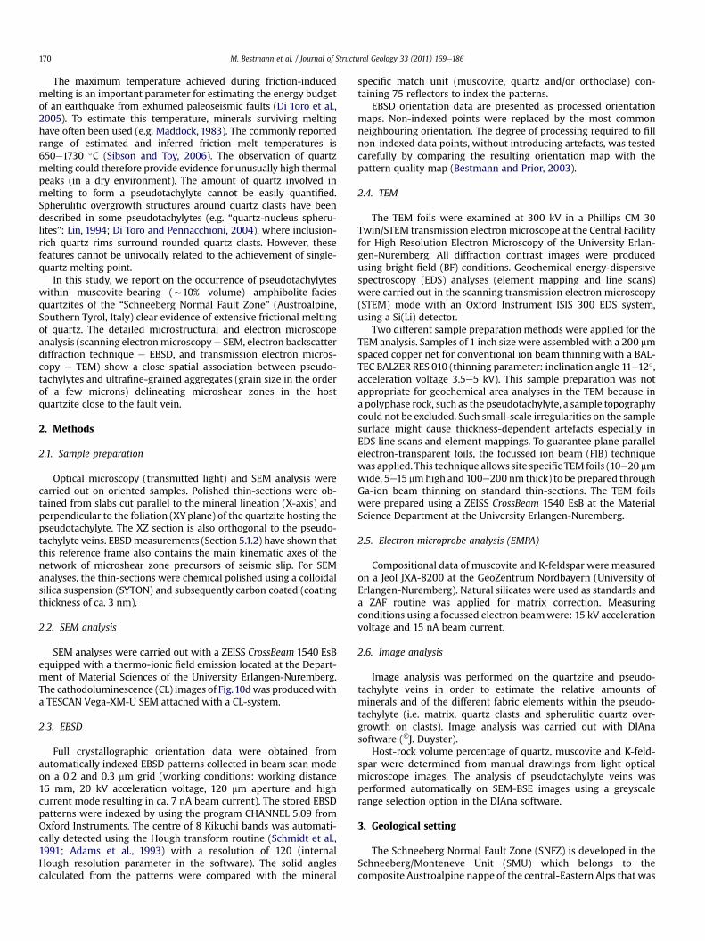
Towards the microshear zone, the size of subgrains decreasesand the orientation contrast pattern becomes diffuse. Related tothese highly deformed host domains, TEM images show both thelocal appearance of a high dislocation density and the preferentialarrangement of dislocations to define a subgrain mosaic (mainsubgrain size of 300e500 nm) (Fig. 8e). The “subgrain”walls consisteither of disordered dislocations or of ordered arrays dislocations.Towards the interior of microshear zones, the subgrain micro-structure merges into an aggregate of individual ultrafine grains(Fig. 8c, d and f) that are also evident in the orientation map (Fig. 9)(i.e. individual grains are entirely surrounded by high angleboundaries with a misorientation angle > 15�, see Bestmann andPrior, 2003). These new grains have straight or slightly curvedboundaries and build a mosaic of polygonal grains with triple grainjunctions at 120�, and grain sizes in the range of 0.5e2 mm, i.e.slightly larger than subgrains (Fig. 8c, d, f, g and h). They are ingeneral free of dislocations (Fig. 8g). The new grain boundaries arelocally decorated with regular arrays of fluid inclusions (Fig. 8dand g) similar to grain boundary pores commonly described inquartz mylonites (e.g. Mancktelow and Pennacchioni, 2004).
Both the orientation maps and the crystallographic orientationplots reveal a gradual lattice bending of the host quartz towards thehighly-distorted area which merges into the microstructure withnew small grains (Fig. 9a). The pole figures show a rotation of thelattice around one crystallographic a-axis (up to 45� in the highly-distorted areas) in a synthetic sensewhen compared with the senseof shear in the associated microshear zone. For all analysedmicrostructures (see also Fig. SOM1e3), the lattice deflectiongenerally occurs around an axis (sub)parallel to the Y-axis, i.e.coinciding with the vorticity axis of the bulk fault zone (see alsoSection 2.1; Bestmann and Prior, 2003).
The CPO of the small new grains, adjacent to the highly-dis-torted area, scatters statistically around the orientation of the

Fig. 4. Micrograph (crossed polars) of (a) undeformed and (b) deformed muscovite. (c, d) SEM-OC (orientation contrast due to electron channelling processes) image of micro-kinksand subgrain mosaic within deformed muscovite. (e) EBSD data of deformed muscovite. [I] Patten quality (band contrast) map. [II] Orientation map. Each pixel represents anorientation, colour coded with respect to its Euler angles. Substructure is colour coded according to angular deviation from a given reference point (red square). Grey pixels arequartz or non-index points of muscovite. Purple, yellow and green lines mark subgrain boundaries (misorientation <15�), black lines indicate high angle boundaries (>15�). [III]Orientation data along misorientation line (red) are presented as pole figures (equal area upper hemisphere stereoplots of main {planes} and <axes> of muscovite). Note latticedeflection around <�310> and/or <010>. [IV] Misorientation profile AeA’; the continuous change of misorientation angle is displayed with respect to the first point A.
M. Bestmann et al. / Journal of Structural Geology 33 (2011) 169e186 173
distorted host grain (area-2 in Fig. 9a and Fig. SOM1-3). In contrast,the small grains from the interior of the microshear zones showa nearly random CPO with a very weak maximum inherited fromthe host quartz (area-3 in Fig. 9a). This random CPO is also evidentfor the intergranular microshear zones that typically formdiscontinuous layers (50e150 mm in thickness) at the contactbetween the quartzite host-rock and the fault1e3 pseudotachylytesveins (Fig. 9b). Coarser remnants of the host-rock material withinthese ultrafine-grained intergranular microshear zones may showa high dislocation density and subgrain structure. All the quartzdeformationmicrostructures described in the host-rock also occurin clasts embedded within the pseudotachylyte matrix (Figs. 8i, jand 9b).
5.2. Pseudotachylyte
Pseudotachylytes consist of a matrix derived from solidificationand crystallization of a frictional melt (see Section 6.2). Glass anddevitrification microstructures have not been observed. Quartzclasts within the pseudotachylyte matrix were derived from boththe coarse quartzite grains and the ultrafine-grained recrystallizedaggregates (see Section 6.3). The quartz clasts show differentmicrostructures and have been differentlymodified during the hightemperature stages related to melting (see Section 6.3).
5.2.1. Quartz clasts and quartz overgrowths (spherulites) inpseudotachylyte
Quartz clasts (qtz-1) range in size from <1 mm to a few 100 mm(Figs. 7a, 8i, 10 and 12a, b) with a dominant grain size of 0.5e3 mm,similar to the grain size of quartz aggregates within the microshearzones of the host quartzite (Fig. 11b). They have a variable shape,from angular to rounded, depending on their position within thepseudotachylyte veins. Some coarse (10’s to 100’s mm in size) clastsshow embayments (Fig. 13a). Coarse clasts are both single crystalsand polycrystalline, the latter consisting of fragments of the ultra-fine-grained microshear zones (Figs. 8i and 9b) typically developedin the quartzite adjacent to the pseudotachylytes. Similar to thedescription of the microshear zones in the host quartzite, thepolycrystalline clasts consists of a compact, ultrafine-grainedmicrostructure with a nearly random CPO (Fig. 9b-II).
Cathodoluminescence (CL) shows bright, thin (<1 mm) rimsaround quartz clasts (Fig. 10d). Locally, within polycrystallinequartz aggregates, a bright diffuse CL patternmay appear related toan ultrafine-grained microstructure. In SEM-BSE (back-scatteredelectron) images such clasts show a transition from a discontin-uous decoration of the quartz grain boundaries of the ultrafine-grained microstructure from tiny blebs of K-feldspar �muscovite(inner part of the clast) to a honeycomb microstructure (out-er part), where the single small quartz grains are completely

Fig. 5. Optical microstructures of the pseudotachylyte-bearing fault network. (a) Thin-section view (plane parallel light) of fault1a and one major antithetic fault3. The orientation ofthe main foliation in the quartzite ranges from sub-parallel to fault1a (lower part) to oblique (upper part), inclined to up 30� and abutting abruptly against the slip surface. Somesmall pseudotachylyte pockets (yellow arrow) and injection vein (black arrow) are marked along fault1a. (b) Enlargements in [I] and [II] (photomontage of plane parallel light -pseudotachylyte, pst - and crossed polars with additional gypsum plate - quartz, qtz) show that fault vein pockets are controlled by the intersection of localized microshear zones, athigh angle to the slip surface, with fault1a (see also Figures SOM2 and 3). Note in [I] the offset of clast along microshear zone. (c) Detail of fault3 (f3) (I: plane polarized light; II:crossed polars; III: crossed polars and gypsum plate). White arrows indicate localized ultrafine-grained microshear zones in the “damaged” quartzite host adjacent and (sub)parallelto the pseudotachylyte vein. Note dextral sense of shear is given because of antithetic fault3 set. (d) Intragranular microshear zone within a deformed host quartz (location is shownin c-III); see Fig. 8aeg for detailed SEM and TEM microstructures. (e) Thin-section view (plane parallel light) of fault1a and one major synthetic fault3 extending on the right side of(a), showing the location of (f) and of images in Fig. 12a. (f) Twomicroshear zones within quartzitic host-rock at fewmillimetres distance from the main fault1a oriented both parallelto the fault1a (f1a) vein and to synthetic fault3 veins.
M. Bestmann et al. / Journal of Structural Geology 33 (2011) 169e186174

Fig. 6. (a) Distorted and folded quartz host foliation towards the main pseudotachylyte-bearing fault plane. (b) Enlargement of deformation microstructure.
Fig. 7. Eye-shaped flow structure (likely a section of a sheath fold) within the main fault1a vein. Micrographs with (a) plane polarized light and (b) crossed polarized light. The flowstreaks are marked by colour banding in (a). Note crushed host-rock below eye-shaped fault vein pocket.
M. Bestmann et al. / Journal of Structural Geology 33 (2011) 169e186 175
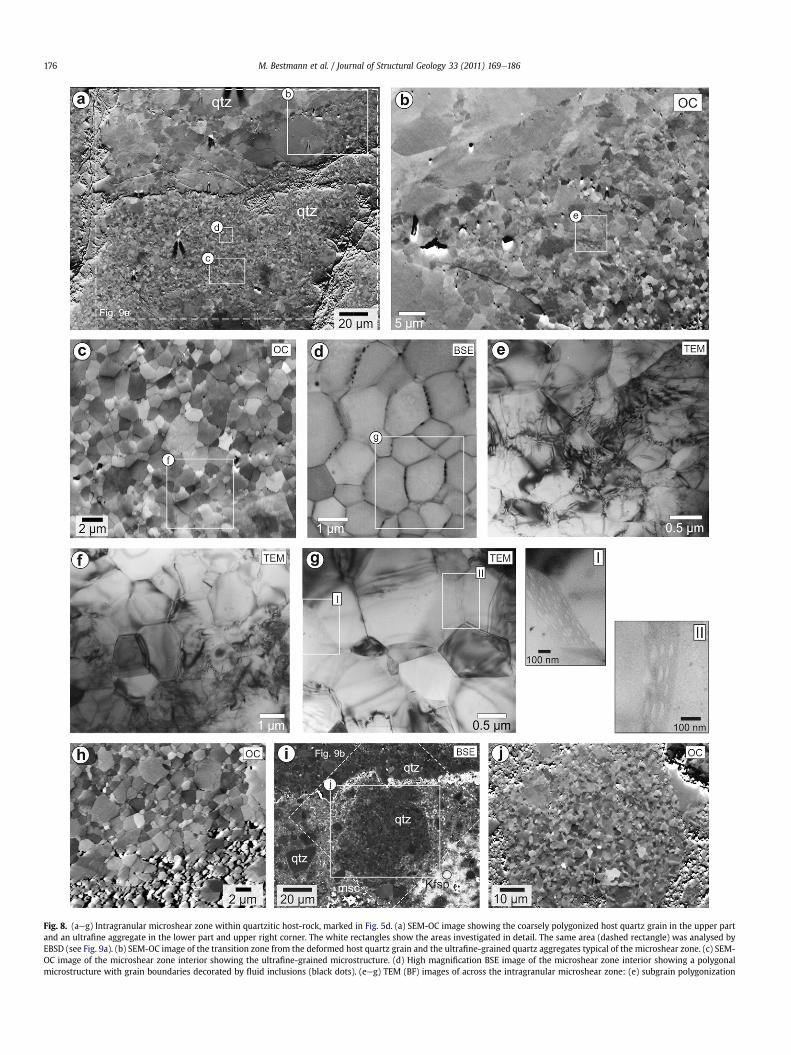
Fig. 8. (aeg) Intragranular microshear zone within quartzitic host-rock, marked in Fig. 5d. (a) SEM-OC image showing the coarsely polygonized host quartz grain in the upper partand an ultrafine aggregate in the lower part and upper right corner. The white rectangles show the areas investigated in detail. The same area (dashed rectangle) was analysed byEBSD (see Fig. 9a). (b) SEM-OC image of the transition zone from the deformed host quartz grain and the ultrafine-grained quartz aggregates typical of the microshear zone. (c) SEM-OC image of the microshear zone interior showing the ultrafine-grained microstructure. (d) High magnification BSE image of the microshear zone interior showing a polygonalmicrostructure with grain boundaries decorated by fluid inclusions (black dots). (eeg) TEM (BF) images of across the intragranular microshear zone: (e) subgrain polygonization
M. Bestmann et al. / Journal of Structural Geology 33 (2011) 169e186176

M. Bestmann et al. / Journal of Structural Geology 33 (2011) 169e186 177
surrounded by the K-feldspar �muscovite matrix (Fig. 10b and c).This process of progressive invasion along the former grainboundary structure leads to disaggregation of the ultrafine-grainedquartz aggregates into small quartz clasts (grain size of 0.5e3 mm)(Fig. 10c).
Initial pseudotachylyte microstructures preserved along themain fault planes (fault1a) showthat theultrafine-grainedportionofquartz clasts within the pseudotachylyte matrix is in part pre-determined by the grain size refinement of quartz along themicroshear zones which preceded seismic faulting (Fig.11b). In fact,the large dominance of quartz clasts with a small grain size of0.5e2 mm within the pseudotachylyte veins mostly results fromcataclastic disaggregation by grain boundary parting of the ultra-fine-grained recrystallized quartz, initially formed alongmicroshearzones in thehost rock, during the initial state of the coseismic failure.
These quartz clasts (qtz-1) are mostly surrounded by a 0.2e1 mmthick rim (qtz-2) forming quartz spherulites (Fig. 13aef). TEMeEDS(energy-dispersive spectrometry) element mapping (Fig. 13d), EDScompositional profiles (Fig. 13e) and BSE-SEM imaging (higherZ-contrast in Fig. 13a) all show an enrichment of Fe and Ti in thespherulitic qtz-2 rim. Small inclusions of mica (mainly biotite, witha grain size up to 700 nm) and Ti-phases (ilmenite and rutile, witha grain size of 50e200 nm) are abundant in qtz-2. The inclusionswithin qtz-2 mostly have a euhedral shape. Elongated to roundedilmenite and rutile are often concentrated at the boundary betweenqtz-1 and qtz-2 (Fig. 11c-II), and/or at the outer surface of thisspherulite rim (Fig. 13e, f). Muscovite and biotite flakes, commonlywith rounded ends, are present as monomineralic flakes andsometimes as combined crystals (Fig. 13f).
The qtz-2 rim surrounding single crystal qtz-1 is monocrystallineand overgrows the core clast epitaxially. Radial growth of poly-crystalline spherulitic rims occurs locally in the case of poly-crystalline clasts (Fig.12b-II). The spherulitic qtz-2 rim around clastsismorepronounced in the centre of the thickest (>500 mm)portionsof fault1þ2 veins, within fault3 veins and injection veins (Fig. 12).
Theqtz-2 spherulites are in turn locallyovergrownbyanepitaxialrim of almost pure, inclusion-free quartz (qtz-3) (Figs. 12b-III and13g). Only few dislocations are present within qtz-3 (Fig. 13g, h). Inareas of high spherulite density, the qtz-3 rims of adjacent spheru-lites impinge against each others and build amosaic aggregate (witha 2e5 mm grain size) with polygonal grains, cored by qtz-2 spheru-lites, showing triple junctions at 120� (Fig.12b-III and c-II). The grainboundaries of these spherulite-cored qtz-3 aggregates are typicallydecorated with fluid inclusions (Figs. 12b-III, c-II and 13g, h). Theformation of polygonal qtz-3 fabrics mainly occurs within fault3(Fig. 12b-III) and injection veins (Fig. 12c-II) and are rarely observedin fault1 veins.
5.2.2. Pseudotachylyte matrixIn the SEM-BSE images of Fig. 12a and b, at a relatively low
magnification, three different domains can be distinguished: (i)dark-grey, coarse clasts of quartz, (ii) grey pseudotachylytesdomains, including the coarse clasts, and (iii) irregular whitepatches. The grey areas of the pseudotachylyte correspond todomains volumetrically dominated by small quartz clasts over-grown by qtz-2 rims (the trace amounts of Ti and Fe explains thelighter BSE grey level compared with the quartz clasts, Fig. 13aand d). Between the small quartz spherulites there is an interstitial
structure and local high dislocation density in the transition zone between host grain and rright part), with characteristic subgrain structure/high dislocation density, and new small disgrains forming a mosaic aggregate with straight grain boundaries forming typical triple junctgrain boundaries. (h) SEM-OC image of a microshear zone (upper part) along the margin of p(undeformed, left, and polycrystalline ultrafine-grained aggregate of former deformed host-and 12b): qtz ¼ quartz; msc ¼ muscovite; kfsp ¼ K-feldspar. Note ultrafine-grained host-rocThe dashed rectangle marks the area analysed by EBSD (see Fig. 9b). (j) Detail of the micro
matrix formed by K-feldspar þ muscovite. The large white patchesin the pseudotachylytes consist of K-feldspar (orthoclase, Kfsp,identified by EBSD pattern analysis). No compositional zoning ofKfsp is evident in the SEM-BSE images (Fig. 12b-I, c-I). EBSD analysisreveals that these patches consist of large (up to several 100’s mm)skeletal single crystals grown within the dispersed cloud of quartzclasts and quartz spherulites (Fig. 14). TEM images show the pres-ence of only few dislocations and the rare subgrain boundarieswithin the Kfsp (Fig. 13c). Kfsp contains small inclusions of zircon,apatite, Fe-sulfide and mica.
5.2.3. Pseudotachylyte vein structureThe ratio between clasts and matrix, their spatial distribution
and their microstructures vary at different positions in a pseudo-tachylyte vein and between the different veins. The different fabriccomponents (qtz-1 clasts, qtz-2 and qtz-3 rims, and matrix) couldbe discriminated automatically by image analysis (see Section 2.6)of SEM-BSE photos by their different greyscale colours: (i) white-light grey for K-feldspar and muscovite, (ii) medium grey forimpure qtz-2 spherulitic rims, and (ii) dark grey for qtz-1 clasts andqtz-3 mosaic (not distinguishable by the applied image analysemethod). Data were collected from mosaics of SEM-BSE imagestaken at 150� (image resolution 2048 � 1536) and 200� (imageresolution 1026 � 624) magnification to allow a meaningful areato be analysed. A test of the reliability of the data collected in thisway was made on mosaics of images with 500� magnification(3072 � 2304) taken from parts of the 200� magnificationmosaic-area.
On average, the fault1þ2 veins contain 21e25 vol.% qtz-1,63e64 vol.% qtz-2 and 11e13 vol.% K-feldspar (þmuscovite) and1e2 vol.% inclusions. Qtz-3 rarely appears in fault1þ2 veins. Fault3veins contain 35e40 vol.% qtz-1 and qtz-3, 43e49 vol.% qtz-2,12e14 vol.% K-feldspar (þmuscovite), and 1e2 vol.% inclusions.
A major difference between the fault1þ2 veins and fault3 injec-tion veins is the distribution and size of the K-feldspar matrixpatches. The pseudotachylyte matrix appears strongly intermixedwith the quartz domains in the fault1þ2 veins, whereas quartz-1-2-3and K-feldspar form separate domains in the fault3 injection veins.
6. Discussion
6.1. Quartz melting in pseudotachylyte
The pseudotachylytes within the SNFZ quartzite provide un-equivocal evidence of extensive friction-induced melting of quartz.In SNFZ pseudotachylytes, the volume of quartz spherulitic rims,crystallized from the melt, accounts for more than 60 and 40 vol. %in fault1þ2 and fault3 veins, respectively. Considering that the host-rock contains up to 12 vol.% of muscovite (�1e2% K-feldspar),which to a first approximation corresponds to the volume fractionof K-feldspar�muscovite in the matrix, the largest part of the meltmust have been almost pure silica derived from the host quartz andcannot be ascribed to a process of fractionation (e.g. Warr and vander Pluijm, 2005). Extensive melting of quartz in tectonic pseudo-tachylytes is not usual and quartz is commonly reported as survivorclasts within the pseudotachylyte matrix. However, rounded andembayed clasts within the matrix have been reported as evidenceof local partial melting (Boullier et al., 2001). Di Toro and
ecrystallized aggregate; (f) transition between a deformed host quartz remnant (lowerlocation-free grains within the microshear zone, and (g) dislocation-free new polygonalion at 120�; the enlargement [I, II] show arrays of voids (fluid inclusions) along straightseudotachylyte veins (lower part). (i) SEM-BSE (atomic contrast) image of quartz clastsrock, centre) within the pseudotachylyte (the location of this site is marked in Figs. 5ck microshear zone in direct contact to pseudotachylyte vein (upper part of the image).structure (SEM-OC image) of clast marked in (i).

Fig. 9. EBSD analysis of quartz in (a) an intragranular microshear zone in the host quartzite (see location in Figs. 5d and 8a) and (b) along fault vein margin and, as a clast, within thepseudotachylyte (pt) vein (see location inFigs. 5c and8i). [I] EBSDorientationmaps; in the imageeachpixel is colour codeddependingonquartzorientation (Euler angles). The substructureofhostquartz in (a) is colour codedaccording to angulardeviation fromagiven referencepoint (small red square in theupperpartof the image). Boundary levels are colour-coded (seekey).[II] Polefigures of<c>,<a> and<m> axes. For (a) the orientation data of thehost domain (blue, area-1), small grains adjacent to thedeformedhost (area-2; one point per grain) and smallgrains within the intragranular deformation zone (area-3; one point per grain) are plotted; for (b) the data of the ultrafine-grained deformation zone in the host adjacent to the pt vein(margin, onepointpergrain) and thepolycrystallinequartzclastwithin thept veinaregiven (clast, onepointper grain).Thepoint colours in theplotsare the sameas in theEBSDmaps.Notein (a-II) lattice distortion in the host grain indicates dextral shear sense (because antithetic fault3 set)with a general rotation axis around one of the<a> axis of the host quartz. Polefiguresare presented as equal area upper hemisphere stereoplots. In order to discriminate between þa and ea axes upper and lower hemisphere plots are presented for <11e20> direction.Multiples of random distribution (MRD) is colour coded in contoured pole figures (half width 15� , data clustering 5�). Red colour marks maxima, also given as numerical number (MRD).
M. Bestmann et al. / Journal of Structural Geology 33 (2011) 169e186178

Fig. 10. Interaction between quartz clast and melt. (a) Optical micrograph (crossed polars) of a polycrystalline clast in fault1 vein. (b) BSE image of the same area as in (a). Note thatthe ultrafine-grained, recrystallized portion of the quartz clasts disaggregates into single grains along the grain boundaries at the periphery of the clast due to intrusion of melt,indicated by a K-feldspar-muscovite matrix (white box)(enlargement in (c)). In the BSE image: qtz-1 is black to dark-medium grey (depending on the crystallographic orientationcontrast e the used four-quadrant BSE detector produce, in addition to the Z-contrast, an orientation contrast signal), qtz-2 is medium to light grey, and K-feldspar þ muscovite islight greyewhite medium grey. (d) SEM-CL image of the same area as in (aeb). The coarse-grained quartz clast shows a bright CL narrow rim. In the case of polycrystalline clastportions the bright CL signal is pervasive, even in the clast interior where there are only a sparse isolated small blebs of melt-derived pockets.
M. Bestmann et al. / Journal of Structural Geology 33 (2011) 169e186 179
Pennacchioni (2004) showed that, in contrast to plagioclase, whoseamount (total clast area) significantly decreases towards the centreof thick (>1 cm) pseudotachylyte veins, quartz remains approxi-mately constant across the veins. This was interpreted as evidencethat in the centre of the vein, where high melt temperatures lastedfor a longer time, plagioclase was consumed by melting whereasquartz was not; the initial melt temperature was inferred to havebeen between 1200 �C (plagioclase single-phase melting under dryconditions) and 1720 �C (quartz single-phase dry melting) (Deeret al., 1992). It is to point out that none-equilibrated frictionalmelting during coseismic events predicts that melting only occursat the melting temperature higher than that of each individualrock-forming mineral (Lin, 2008).
In the case of the SNFZ pseudotachylytes, melting of quartzshould indicate a melt temperature of 1720 �C, assuming dryconditions (Deer et al., 1992). The absence of free water fluids, andfluid-deficient conditions in general, are a common assumption forpseudotachylytes (Spray, 1992). The effect of a free fluid phasealong a fault plane during seismic slip would cause shear heating-induced thermal pressurization of the fault and a loss of frictionalresistance (Sibson, 1973; Mase and Smith, 1987; Otsuki et al., 1999),precluding the onset of friction-induced melting. However, theassumption of dry conditions during pseudotachylyte generation isnot probably always correct, as it is suggested by the coexistence ofpseudotachylytes and epidote-chlorite veins at the contractionaland extensional bends, respectively, of undulated fault surfaceswithin the Sierra Nevada (Griffith et al., 2010).
In the SNFZ quartzite, water fluids were certainly releasedduring frictional melting of muscovite. Water was probably also
present as a free fluid phase before coseismic slip, as abundantfluid inclusions present along the grain boundaries of ultrafine-grained recrystallized quartz of themicroshear zones and, as trails,in the host coarse-grained quartz (Krenn, 2010). Fluids can beincorporated in a melt as dissolved volatiles and this wouldprevent thermal pressurization of the fault. Boullier et al. (2001)inferred about 8 vol. % of volatiles dissolved in the frictionalmelt on the basis of the EMPA-determined composition of theglassy matrix of pseudotachylytes within a granodiorite exhumedalong the Nojima Fault (Japan). The presence of fluid inclusions inthe Nojima pseudotachylyte glass provides evidence of H2O andCO2 saturation in the melt, originating from melting of H2O-bearing minerals and carbonates. Thus potentially a relativelylarge amount of fluids can be stored in the melt, although fluidsolubility in a melt is largely dependent on melt composition andon pressure.
Under the same ambient conditions, muscovite has a lowersingle-mineral melting temperature than quartz (ca. 1300 and1720 �C, respectively, under dry conditions) and should undergomelting at an earlier stage according to the general assumption forpseudotachylytes of non-equilibrium (non-eutectic) fusion (Lin,2008). In the SNFZ pseudotachylytes, this is supported by theobservation that within clasts of the former compact ultrafine-grained recrystallized quartz the grain boundary networkwasfilledwith K-feldspar þ muscovite (Figs. 11b and b-I) mainly derived bymuscovite melting. At that intial stage of coseismic frictionalsliding, there is no clearmicrostructural evidence of involvement ofquartz in melting (see also section 6.2). Therefore, water fluidsproduced by muscovite melting could have been incorporated in

Fig. 11. Microstructural inventory of pseudotachylyte veins. (a) Sketch of fault1þ3 veins (simplified from Fig. 5a and e) and location of BSE images of (bec) and Fig. 12. (b) Ultrafinerecrystallized aggregate in the host quartzite (upper part) with a sharp contact with a pseudotachylyte vein (lower part) mainly formed of a dense population of quartz clasts, ofa comparable grain size as the small grains in the wall rock, and an interstitial K-feldspar þ muscovite matrix. (b-I) Detail of the microstructure in the pseudotachylytes. Quartz grainsdo not show any evident overgrowth. Kfsp ¼ K-feldspar; msc ¼ muscovite. (c) Heterogeneous microstructure in the pseudotachylytes including irregular domains dominated by K-feldspar matrix and clast-dominated portions with subordinate interstitial K-feldspar þ muscovite. (c-I) Detail of a clast-dominated domain showing quartz clasts surrounded byspherulitic rims (qtz-2) enhanced by the lighter grey (due to a change in Fe and Ti composition, see Fig. 13) than the qtz-1 cores and by the presence of concentrations of brightinclusions (Fe, Ti phase, see Fig. 13) at the interface between qtz-1 and qtz-2. (c-II) Detail of a matrix-rich domain showing small quartz spherulites embedded in the Kfsp �msc matrix.
M. Bestmann et al. / Journal of Structural Geology 33 (2011) 169e186180
part into the early K-rich melt before the occurrence of extensivequartz melting. Fluids present along the quartz grain boundariescould also have been dissolved in the early melt during fluidpercolation through grain boundaries of (ultra)fine aggregates. Asa result, some degree of hydrated conditions during melting, andconsequently lower temperature of fusion of single minerals thanunder dry conditions, can be reasonably assumed during seismicslip in the SNFZ quartzite. For example, the melting point of quartzcan vary from1100 to1720 �C, depending on bothwater activity andpressure (Kennedy et al., 1962). The first melting of quartz is
documented by the appearance of rounded small quartz clasts andembayed coarser quartz clasts (e.g. Sibson, 1975; Lin, 1999;Magloughlin, 1992) (Fig. 11c-I). Subsequently, these clasts act asnuclei for concentric growth of impure secondary quartz (qtz-2)from a quartz-rich melt (Sato, 1975; Macaudiére et al., 1985;Lin, 1994) (see also section 6.2). Hydrated conditions during crys-tallization of quartz are also suggested by the crystallization ofbiotite/muscovite, forming small idioblastic inclusions in thespherulitic qtz-2 rims (Fig. 13e, f) and by fluid inclusions along theqtz-3 grain boundary network (Fig. 12b-III and 13h).

Fig. 12. Inventory of BSE microstructural images from (a) fault1, (b) fault3 and (c) injection veins. (a) Overview of fault1. (b) Overview of fault3. (b-I) Spherulitic quartz clasts (qtz-1 þ qtz-2) floating in a locally homogeneous Kfsp matrix. (b-II) Polycrystalline spherulitic rim of radially distributed qtz-2 crystals surrounding a polycrystalline quartz-1 clasts andmonocrystalline spherulite around single grain clasts. (b-III) Mosaic fabric of equate, inclusion-free impinging qtz-3 overgrowths. Note the presence of small fluid inclusions (darkdots) along the grain boundaries. (c) Zoned pseudotachylyte injection vein including a quartz (qtz-1 þ qtz-2) spherulite-dominated interior and a Kfsp matrix-dominated zone at thecontact with the wall rock. (c-I) Detail of the sharp contact between quartz spherulite-dominated domain (inner vein) and the Kfsp matrix-dominated domain (vein border). (c-II)Detail of qtz-1-3 aggregate in the Kfsp matrix-free pseudotachylyte inner domain.
M. Bestmann et al. / Journal of Structural Geology 33 (2011) 169e186 181
Fig. 13. (aef) Microstructural and geochemical analysis of quartz spherulites within Kfsp matrix, marked in Fig. 12b. (a) SEM-BSE image showing the sectional line (white), alongwhich the TEM-lamellae was prepared, across quartz spherulites in a K-feldspar matrix. (b) Compositional contrast image obtained with SEM�SE2 detector of the TEM lamellae. (c)TEM (bright field) image of the area marked in (b) showing the quartz spherulites within the Kfsp matrix. Note Kfsp matrix shows only few dislocations. (d) TEMeEDS (energy-dispersive spectrometry) element maps of spherical quartz spherulite. (e) Element (EDS) profile across quartz spherulite (qtz-1 and qtz-2). Note slightly enhanced content of Ti andFe within qtz-2 as marked along stippled line in the TEM image and as white area in the Ti and Fe element line profiles. (f) Microlite inclusions of biotite (Bt), muscovite (msc) withinand ilmenite at the margin of qtz-2. (g) TEM microstructure of qtz-2 and qtz-3 developed within fault3 vein. Note qtz-2 contains inclusions whereas qtz-3 is “pure” quartz. (h) Fluidinclusions (black arrows) along the grain boundaries of qtz-3.
M. Bestmann et al. / Journal of Structural Geology 33 (2011) 169e186182
The occurrence of extensive quartz melting in the SNFZ pseu-dotachylyte prompts the question as towhy quartz melting is rarelyreported in other pseudotachylytes. The process of quartz meltingcan be overlooked or difficult to detect in pseudotachylytes within
polycrystalline rocks (especially in the ultrafine-grained clast frac-tion), but it is a commonobservation that quartz ismainly preservedas a clast in pseudotachylyte. The common interpretation is thatquartz has a high single-mineral melting temperature and, under

Fig. 14. EBSD analysis of the K-feldspar fabric of the pseudotachylyte martrix. (a) SEM-BSE image of the analysed area within a fault3 vein (location is shown in Fig. 12b). (b)EBSD orientation map of Kfsp matrix. Note that the matrix consists of large (several 10sof microns) amoeboid single crystals of different orientation. Note subgrain boundariesare rare. (c) Pole figures of Kfsp crystallographic orientation. Figure description forEBSD data presentation follows those for Fig. 9.
M. Bestmann et al. / Journal of Structural Geology 33 (2011) 169e186 183
the commonly assumed almost dry conditions in pseudotachylytes,it would escape melting even in superheated melts (Di Toro andPennacchioni, 2004). As discussed above, the SNFZ quartziteinitially contained water fluids and water-bearing phases, and
melting under hydrous conditions can dramatically lower themelting temperature of quartz and other minerals. However, fric-tion-induced melting in rock containing hydrous mineral phases(and thus capable of releasing aqueous fluids during coseismicfaulting), as well as intragranular and grain boundary fluidinclusions, appears to be common rather than the exception.Many pseudotachylytes are preceded by cataclastic deformation(Magloughlin, 1992), which is commonly associated with a largefluid influx and rock alteration (Boullier et al., 2001; Di Toro andPennacchioni, 2004; Caggianelli et al., 2005). Another explanationfor the limited quartz melting in quartz-bearing polymineralic rockis that the melting of large amounts of minerals with a lowermelting point than quartz buffers the frictionmelt temperature dueto latent heat of fusion. This would impede the temperature riseuntil the complete consumption of theseminerals. For example, thetonalite described by Di Toro and Pennacchioni (2004) consists ofplagioclase (45e50% in volume), quartz (25e30%), biotite (15e20%)and K-feldspar (1e5%) and consequently a large amount of the totalfrictional heat generated along the fault plane must have been usedfor the complete melting of >70% of the rock volume before thetemperature could rise to the melting point of quartz. In contrast,after consumption of the minor volume of muscovite in the SNFZquartzite, heat was readily available to increase temperature.Therefore, under similar ambient conditions and amount ofcoseismic slip, quartz melting is more likely effective in a quartzitethan in quartz-bearing crustal rocks. The validity of this speculationis difficult to assert, given the non-equilibrium character of friction-induced melting.
6.2. Immiscible friction-induced melts
The SNFZ pseudotachylytes show two distinct componentsderived from crystallization of the friction-induced melts, namely:the K-feldspar � muscovite matrix and the qtz-2 and qtz-3 over-growths of qtz-1 clasts. These two melt-derived componentsdeveloped at different stages in the friction-induced meltingprocess and represent distinct, immiscible melts. The formerdeveloped at an earlier stage due to melting of muscovite thatunderwent complete fusion in the frictional melt. This is suggestedby the incipient filling of pore space and dilatants grain boundariesof the clasts of ultrafine-grained quartz with K-feldspar andmuscovite; at this stage of pseudotachylyte evolution, there is noevidence of development of any qtz-2 rim in the “melt-infiltrated”aggregate (Fig. 11b and b-I). The absence of transitional domainswith an intermediate composition indicates that the K-rich andsilica-rich melts were almost immiscible. However some“contamination” of the quartz melt is indicated by the presence ofthewidespread small (50e200 nm) biotite/muscovite, ilmenite andrutile inclusions preserved in the spherulitic rims, together withthe Ti- and Fe-enriched qtz-2 composition (Fig. 13d, e, f). The localovergrowth of qtz-2 spherulites by an almost pure inclusion-freequartz-3 fabric gives evidence that quartz melt changed composi-tion with time. These qtz-3 overgrowths mainly developed alongfault3 zones and injection veins, whereas they appear absent alongthe main fault1 veins where melts underwent pervasive shearing,flow and mechanical mixing after formation.
The size and the rounded shape of ilmenite and rutile inclusionswithin the qtz-2 rims and in contact to the qtz-3 overgrowth seemsto exclude that they are fragments derived from the host-rock.Instead, the concentrations of Fe- and Ti-rich minerals withinthe qtz-2 rims are considered to have formed by the preferentialfractional crystallization of mafic minerals from the melt (Warr andvan der Pluijm, 2005). Geochemical TEM analysis reveals thata small amount of Ti and Fe (Fig. 13e) are also incorporated into theqtz-2 lattice, which is why qtz-2 appears medium grey in electron

M. Bestmann et al. / Journal of Structural Geology 33 (2011) 169e186184
backscatter images. The concentration of idioblastic inclusions ofilmenite and rutile at the inner or outer part of qtz-2 rim, withrespect of the position of the spherulites within the fault veins,indicates an early and late state of preferred crystallization of theFeeTi phases from the melt. Ti and Fe could be released duringmelting of muscovite, which contains 2e7 wt.% FeO and up to2.6 wt.% TiO2. Melting of the FeeTi ore phase from the host-rockcould also be a source for Fe and Ti. This would imply friction-induced melting points of 1356 �C for ilmenite, 1475e1565 �C forhematite and 1825 �C for rutile.
6.3. Ductile microshear zones associated with pseudotachylyte
Pseudotachylytes are spatially associated with microshearzones in the host-rock showing recrystallization of quartz toultrafine-grained aggregates. The host-rock coarse quartz grainsadjacent to themicroshear zones showdeflection and reorientationof the lattice around rational crystallographic axes (Fig. 9a), typicalof crystal plastic deformation and dislocation creep (Lloyd andFreeman, 1994; Lloyd et al., 1997; Prior et al., 2002; Bestmann andPrior, 2003; Bestmann et al., 2008). The dislocation substructuresare also indicative of crystal-plasticity. The development of a sub-grain mosaic with partly well-ordered dislocations walls (Fig. 8e)adjacent to areaswith a high dislocation density (with a lowdegreeof organization) indicates that both dislocation creep and disloca-tion glide took place. The small new grains adjacent to stronglydeformed host-rock quartz have a crystallographic orientationslightly misoriented with respect to that of the host and showa dispersion around rational axes close in orientation to the Y-axis(the vorticity axis of bulk deformation). The grain size of newgrainsis of the same order of magnitude as the subgrain size in the host.These features would be consistent with subgrain rotation recrys-tallization. In detail, the new recrystallized grains are slightlycoarser (0.5e2 mm) than the subgrains (0.3e0.5 mm) in the parentquartz, probably due to post-kinematic static grain growth. Asa result, an equilibrated grain boundary network of strain free newgrains within the microshear zones developed (Fig. 8d, g).
The randomization of the CPO of the new small grains within themicroshear zone (Fig. 9a) might be related to the activity of grain-size-sensitive (GSS) grain boundary sliding, subsequent to grainsize reduction by subgrain rotation recrystallization (De Bresseret al., 2001; Bestmann and Prior, 2003). Thus we infer that newrecrystallized grains, once formed, are able to deform and rotate bygrain boundary sliding and cause a weakening of the formerexisting CPO (Casey and McGrew, 1999; Bestmann et al., 2008).
A detailed discussion about the significance of the plasticdeformation mechanism within the quartzites associated withcoseismic faulting will be published elsewhere. We will comparethe crystal plastic microfabrics (microstructure and CPO) of thesepseudotachylyte-related shear zones with microfabrics interpretedas the result of short-term deformation at high stress in the (semi)brittle regime and subsequent stress release (Trepmann andStöckhert, 2003; Trepmann et al., 2007). In this interpretation,recrystallization and the annealed microstructure of quartz aggre-gates is mainly the result of (dynamic and/or static) recovery of thehighly-distorted and dislocation-rich portions of quartz involved intransient low-temperature crystal-plasticity developed duringdownward propagation of earthquake ruptures to the upper ductilecrust.
6.4. Timing of host-rock deformation and pseudotachylytedevelopment
The fault1�3pseudotachylytes strictly followaprecursor networkof localized microshear zones characterized by strong grain size
reduction. Once formed, these deformed zones were preferentiallyused as slip surfaces during coseismic slip. The aggregates ofultrafine-grainedmicroshear zones are present in the host quartziteat the contact or at a small distance from pseudotachylyte and areincluded as clasts within the veins. This indicates a phase of local-ized plastic deformation prior to the formation of the pseudo-tachylytes. The kinematics of deformation in the microshear zones(constrained by EBSD data, Fig. SOM1) is consistent with both thegeneral top-to-NW sense of shear in the high temperature fabric ofthe SNF (Sölva et al., 2005; G. Cotza, personal comment) and thesense of shear during the coseismic faulting generating the pseu-dotachylyte veins (constrained by flow fabrics, Fig. 7a andFig. SOM4).
The question arises of whether the ultrafine aggregates devel-oped at different ambient (P, T) conditions than coseismic slip,during a separate, pre-existing deformation phase, or duringa precursory, almost coeval stage to the pseudotachylytes-gener-ating event and thus belong to the seismic cycle. The actual timelapse between pre-seismic crystal plastic grain size reduction andcoseismic rupture process is difficult to constrain. However, thefollowing microstructural observations point to a continuous pre-to coseismic crystal plastic deformation of quartzitic host-rockmaterial: (i) the development of melt pockets along fault1 planes iscontrolled by microshear zones where the displacement-relatedopening space is directly filled with pseudotachylyte material(Fig. 5b and Figs. SOM2 and SOM3), (ii) the distorted and foldedquartz host foliation near the main pseudotachylyte-bearing faultplanes shows the same crystal plastic deformation microstruc-tures (Fig. 6) and (iii) flow structures of deformed host quartzaggregates within pseudotachylyte veins are characterized by thesame crystal plastic induced grain size reduction processes andmicrostructures (Fig. SOM4).
Recently, high-velocity rotary shear experiments on calciteCarrara marble at coseismic slip rates have produced similarmicrostructures as described here for the SNFZ pseudotachylytes.The marble also show a plastic deformation of the wall rock (bentcalcite deformation twins accompanied by patchy unduloseextinction) and a layer of ultrafine-grained (2e5 mm) calciteaggregates with equilibrated grain boundaries adjacent to theprincipal slip layer (Figure DR5 in Kim et al., 2010).
Our observations suggest that the fault-related plastic defor-mation microstructures of the pseudotachylyte-bearing SNFZquartzite were coseismic and related to heterogeneous slip andstrain rates during a single seismic event, consistently with theexperimental observation of Kim et al. (2010). This could haveoccurred during the acceleration stages of the seismic faulting or bystrain rate partitioning in host rock during the coseismic slip alongthe principal pseudotachylyte-bearing plane.
Post-seismic deformation can be excluded since, within thepseudotachylyte veins, neither the K-feldspar nor the qtz-2 and qtz-3 aggregates (both crystallized form the friction-induced melt)show any internal deformation microstructure (Fig. 13c, g, h). Evenminor reactivation deformation or recrystallization would haveoverprinted these nearly dislocation-free microstructures. Thusneither host-rock nor coexisting pseudotachylyte veins showevidence of a multiphase deformation history.
7. Conclusions
During a single-jerk seismic event, pseudotachylyte veinsdeveloped at coseismic slip rates in the muscovite-bearingquartzite of the SNFZ (Southern Tirol, Italy) with extensive meltingof quartz. During the same faulting event, crystal plastic deforma-tion in the host-rock produced ultrafine-grained microshear zones.

M. Bestmann et al. / Journal of Structural Geology 33 (2011) 169e186 185
Microstructural analysis provides unambiguous evidence ofextensive quartz melting. This does not necessarily indicate melttemperatures as high as 1720 �C (quartzmelting temperature underdry conditions), since partially hydrated conditions prevailedduring coseismic faulting. Quartz melting in quartzite may be morecommon than in polymineralic rocks (e.g. granitoids) because ofthermal buffering by the latent heat of fusion of the low-meltingpoint minerals. In fact, quartz has one of the highest melting pointsof the common silicate rock-forming minerals.
The occurrence of pseudotachylytes in quartzite suggests thatthe fault-weakening mechanism in quartz described in experi-ments (Di Toro et al., 2004) at low confining pressure may be non-operative at deeper structural levels in the continental crustwhere large earthquakes nucleate and most pseudotachylytes areproduced.
Pseudotachylytes are closely associated with crystal plasticdeformation of the quartzitic host rock along microshear zonesclose to the fault plane. This deformation occurred before andduring the main seismic slip along the pseudotachylyte-producingfaulting. The development of localized plastic deformation duringthe seismic cycle deserves future investigation for a better under-standing of the mechanics of earthquake sources.
Acknowledgment
The authors gratefully acknowledge: Gianluca Cotza forproviding the sample and sample location; Ulli Exner for fieldsupport; Jens Schaufler, Elmar Schweitzer, Matthias Bickermann,Edeltraut Völkel and Florian Heidelbach for electron microscopysupport; Volker von Seckendorf, Nico Langenhof and Jürgen Gosefor microprobe support; Jens Götze and Rolf Neuser for HOT-CLsupport; Hubert Schulze, Angela Halfpenny, Werner Langer, PetraRosner and Friederike Urban for sample preparation; BernhardGrasemann, Gerlinde Habler, Bernhard Schulz, Bernhard Stöckhert,Claudia Trepmann and Markus Ebner for discussion; Hugh Rice forEnglish correction; Claudia Trepmann and Aiming Lin for review-ing the manuscript. Further acknowledgments go to the DeutscheForschungsgemeinschaft (DFG) for funding the project WA 1010/11-1 (Lab and research funding)(MB) and for supporting within theframework of its `Excellence Initiative’ the Cluster of Excellence`Engineering of Advanced Materials’ (www.eam.uni-erlangen.de)at the University of Erlangen-Nuremberg (MG). GP thanks Fon-dazione Cariparo (Progetto di eccellenza “Revealing the secrets ofan earthquake: physico-chemical constraints from a multidisci-plinary study of exhumed faults”) and ERC StG 205175 for financialsupport.
Appendix. Supplementary data
Supplementary data related to this article can be found online atdoi:10.1016/j.jsg.2010.10.009.
References
Adams, B.L., Wright, S.I., Kunze, K., 1993. Orientation imaging: the emergence ofa new microscopy. Metallurgical Transactions 24A, 819e831.
Allen, A.R., 1979. Mechanism of frictional fusion in fault zones. Journal of StructuralGeology 1, 231e243.
Bell, I.A., Wilson, C.J.L., McLare, A.C., Etheridge, M.A., 1986. Kinks in mica: role ofdislocation and (001) cleavage. Tectonophysics 127, 49e65.
Bestmann, M., Prior, D.J., 2003. Intragranular dynamic recrystallization in naturallydeformed calcite marble: diffusion accommodated grain boundary sliding asa result of subgrain rotation recrystallization. Journal of Structural Geology 25,1597e1613.
Bestmann, M., Habler, G., Heidlebach, F., Thöni, M., 2008. Dynamic recrystallizationof garnet and related diffusion processes. Journal of Structural Geology 30,777e790.
Bossière, G., 1991. Petrology of pseudotachylytes from the Alpine fault of NewZealand. Tectonophysics 196, 173e193.
Boullier, A.-M., Ohtani, T., Fujimoto, K., Ito, H., 2001. Fluid inclusions in pseudo-tachylytes from the Nojima fault, Japan. Journal of Geophysical Research 106,21965e21977.
Caggianelli, A., de Lorenzo, S., Prosser, G., 2005. Modelling the heat pulses generatedon a fault plane during coseismic slip: inferences from the pseudotachylites ofthe Copanello cliffs (Calabria, Italy). Tectonophysics 405, 99e119.
Camacho, A., Vernon, R.H., Fitz Gerald, J.D., 1995. Large volumes of anhydrouspseudotachylyte in the Woodroffe Thrust, eastern Musgrave ranges, Australia.Journal of Structural Geology 17, 371e383.
Casey, M., McGrew, A.J., 1999. One-dimensional kinematic model of preferredorientation development. Tectonophysics 303, 131e140.
De Bresser, J.H.P., Ter Heere, J.H., Spiers, C.J., 2001. Grain size reduction by dynamicrecrystallization: can it result in major rheological weakening. InternationalJournal of Earth Sciences (Geologische Rundschau) 90, 28e45.
Deer, W.A., Howie, R.A., Zussman, J., 1992. An Introduction to the Rock FormingMinerals. Longman Scientific and Technical, pp. 696.
Di Toro, G., Pennacchioni, G., 2004. Superheated friction-induced melts in zonedpseudotachylytes within the Adamello tonalites (Italian Southern Alps). Journalof Structural Geology 26, 1783e1801.
Di Toro, G., Pennacchioni, G., 2005. Fault plane processes and mesoscopic structureof a strong-type seismogenic fault in tonalites (Adamello batholith, SouthernAlps). Tectonophysics 402, 54e79.
Di Toro, G., Goldsby, D.L., Tullis, T.E., 2004. Friction falls towards zero in quartz rockas slip velocity approaches seismic rates. Nature 427, 436e439.
Di Toro, G., Pennacchioni, G., Teza, G., 2005. Can pseudotachylytes be used to inferearthquake source parameters? an example of limitations in the study ofexhumed faults. Tectonophysics 402, 3e20.
Di Toro, G., Pennacchioni, G., Nielsen, S., 2009. Pseudotachylytes and earthquakesource mechanisms. In: Fukuyama, E. (Ed.), Fault-zone Properties and Earth-quake Rupture Dynamics. International Geophysics Series, vol. 94. Elsevier,pp. 87e133.
Frey, M., Desmons, J., Neubauer, F., 1999. The New Metamorphic Map of the Alps,EUG 10. Terra Abstracts. Cambridge Publications, Strassbourg, pp. 792.
Griffith, W.A., Nielsen S., Di Toro G., Smith S.A.F., 2010. Rough faults, distributedweakening, and off-fault deformation. Journal of Geophysical Research 115,B08409, pp. 1e22.
Habler, G., Sölva, H., Thöni, M., 2006. Tracing the high pressure stage in the poly-metamorphic Texel Complex (Austroalpine basement unit, Eastern Alps):P-T-t-d constraints. Mineralogy and Petrology 88, 269e296.
Hoinkes, G., Thöni, M., 1987. New findings of eclogites within the eo-Alpineamphibolite grade area of the Ötztal basement. Terra Cognita 7, 96.
Kennedy, G.C., Wasserburg, G.J., Heard, H.C., Newton, R.C., 1962. The upper three-phase region in the SiOeH2O. American Journal of Science 260, 501e521.
Kim, J.-W., Ree, J.-H, Han, R., Shimamoto, T., 2010. Experimental evidence for thesimultaneous formation of pseudotachylyte and mylonite in the brittle regime.Geology 38, 1143e1146.
Konzett, J., Hoinkes, G., 1996. Paragonite-hornblende assemblages and theirpetrological significance: an example from the Austroalpine SchneebergComplex, Southern Tyrol; Italy. Journal of Metamorphic Geology 14, 85e101.
Krenn, K., 2010. Fluid inclusions in quartz related to subsequent stages of foliationdevelopment during a single metamorphic cycle (Schneeberg Fault Zone,Eastern Alps, Austria). Lithos 118, 255e268.
Lin, A., 1994. Microlite morphology and chemistry in pseudotachylite, from theFuyun fault zone, China. Journal of Geology 102, 317e329.
Lin, A., 1999. Roundness of fragments in pseudotachylytes as an indicator of fric-tional melting. Journal of Structural Geology 21, 473e478.
Lin, A., 2008. Fossil Earthquakes: The Formation and Preservation of Pseudo-tachylytes. In: Lecture Notes in Earth Sciences, vol. 111. Springer, pp. 348.
Lloyd, G.E., Freeman, B., 1994. Dynamic recrystallization of quartz and quartzites.Journal of Structural Geology 16, 867e881.
Lloyd, G.E., Farmer, A.B., Mainprice, D., 1997. Misorientation analysis and theformation and orientation of subgrain and grain boundaries. Tectonophysics279, 55e78.
Macaudiére, J., Brown, W.L., Ohnenstetter, D., 1985. Microcrystalline texturesresulting from rapid crystallization in a pseudotachylite melt in a meta-anor-thosite. Contribution of Mineralogy and Petrology 89, 39e51.
Maddock, R.H., 1983. Melt origin of fault-generated pseudotachylytes demonstratedby textures. Geology 11, 105e108.
Maddock, R.H., 1986. Partial Melting of Lithic Porphyroclasts in Fault-GeneratedPseudotachylytes, vol. 155. Neues Jahrbuch für Mineralogie, Abhandlungen,1e14.
Maddock, R.H., 1992. Effects of lithology, cataclasis and melting on the compositionof fault-generated pseudotachylytes in Lewisian gneiss, Scotland. Tectonophy-sics 204, 261e278.
Magloughlin, J.F., 1989. The nature and significance of pseudotachylite from theNason terrane, North Cascade Mountains, Washington. Journal of StructuralGeology 11, 907e917.
Magloughlin, J.F., 1992. Microstructural and chemical changes associated withcataclasis and frictional melting at shallow crust levels: the cataclasite-pseu-dotachylyte connection. Tectonophysics 204, 243e260.
Mancktelow, N.S., Pennacchioni, G., 2004. Microstructures of quartz mylonites:the importance of grain boundary fluids. Journal of Structural Geology 26,47e69.

M. Bestmann et al. / Journal of Structural Geology 33 (2011) 169e186186
Mase, C.W., Smith, L., 1987. Effects of frictional heating on the thermal, hydrologic,and mechanical response of a fault. Journal of Geophysical Research 92 (B7),6249e6272.
Otsuki, K., Monzawa, N., Nagase, T., 1999. Thermal pressurization, fluidization andmelting of fault gouge during seismic slip recorded in the rock from Nojimafault. In: Ito, H., et al. (Eds.), International Workshop of the Nojima FaultCore and Borehole Data Analysis. Geological Survey of Japan, Tsukuba,pp. 43e50.
Prior, D.J., Wheeler, J., Peruzzo, L., Spess, R., Storey, C., 2002. Some garnet micro-structures: an illustration of the potential of orientation maps and misorien-tation analysis in microstructural studies. Journal of Structural Geology 24,999e1011.
Sato, H., 1975. Diffusion coronas around quartz xenocrysts in andesite and basaltfrom Tertiary volcanic region in northeastern Shikoku, Japan. Contributions toMineralogy and Petrology 50, 49e64.
Schmidt, N.H., Bildesorensen, J.B., Jensen, D.J., 1991. Band positions used for onlinecrystallographic orientation determination from electron back scatteringpatterns. Scanning Microscopy 5, 637e643.
Sibson, R.H., Toy, V., 2006. The habitat of fault-generated pseudotachylyte: presencevs. absence of friction melt. In: Abercrombie, R., McGarr, A., Di Toro, G.,Kanamori, H. (Eds.), Earthquakes: Radiated Energy and the Physics of Faulting.Geophysical Monograph Series, vol. 170. American Geophysical Union, Wash-ington, DC, pp. 153e166.
Sibson, R.H., 1973. Interactions between temperature and pore-fluid pressureduring earthquake faulting and a mechanism for partial or total stress relief.Nature 243, 66e68.
Sibson, R.H., 1975. Generation of pseudotachylyte by ancient seismic faulting.Geophysical Journal of the Royal Astronomical Society 43 (3), 775e794.
Sibson, R.H., 1986. Earthquakes and rock deformation in crustal fault rocks. AnnualReviews of Earth Planetary Sciences 14, 149e175.
Sölva, H., Grasemann, B., Thöni, M., Thiede, R., Habler, G., 2005. Normal faultingassociated with cretaceous SE-directed extrusion in the Eastern Alps (Italy/Austria). Tectonophysics 401, 143e166.
Spray, J.G., 1992. A physical basis for the frictional melting of some rock-formingminerals. Tectonophysics 204, 205e221.
Spray, J.G., 1993. Viscosity determinations of some frictionally generated silicatemelts: implications for fault zone rheology at high strain rates. Journal ofGeophysical Research 98, 8053e8068.
Swanson, M.T., 1992. Fault structure, wear mechanisms and rupture processes inpseudotachylytes generation. Tectonophysics 204, 223e242.
Trepmann, C.A., Stöckhert, B., 2003. Quartz microstructures developed during non-steady state plastic flow at rapidly decaying stress and strain rates. Journal ofStructural Geology 25, 2035e2051.
Trepmann, C.A., Stöckhert, B., Dorner, D., Haamidzadeh, R., Küster, M., Röller, K.,2007. Simulating coseismic deformation of quartz in the middle crust and fabricevolution during postseismic stress relaxation d an experimental study. Tec-tonophysics 442, 83e104.
Warr, L.N., van der Pluijm, B.A., 2005. Crystal fractionation in the friction melts ofseismic faults (Alpine Fault, New Zealand). Tectonophysics 402, 111e124.
White, S.R., 2001. Textural and microstructural evidence for semi-brittle flow innatural fault rocks with varied mica content. International Journal of EarthSciences 90, 14e27.