Journal of Sound and Vibration - Laboratory of Sound ... · PDF fileDepartment of Mechanical...
11
Computational and experimental studies of microvascular void features for passive-adaptation of structural panel dynamic properties Nicholas C. Sears, Ryan L. Harne * Department of Mechanical and Aerospace Engineering, The Ohio State University, Columbus, OH 43210, USA article info Article history: Received 28 May 2017 Received in revised form 12 August 2017 Accepted 22 September 2017 Keywords: Adaptive structures Vibration control Mass redistribution Microvascular voids abstract The performance, integrity, and safety of built-up structural systems are critical to their effective employment in diverse engineering applications. In conflict with these goals, harmonic or random excitations of structural panels may promote large amplitude oscil- lations that are particularly harmful when excitation energies are concentrated around natural frequencies. This contributes to fatigue concerns, performance degradation, and failure. While studies have considered active or passive damping treatments that adapt material characteristics and configurations for structural control, it remains to be under- stood how vibration properties of structural panels may be tailored via internal material transitions. Motivated to fill this knowledge gap, this research explores an idea of adapting the static and dynamic material distribution of panels through embedded microvascular channels and strategically placed voids that permit the internal movement of fluids within the panels for structural dynamic control. Finite element model and experimental in- vestigations probe how redistributing material in the form of microscale voids influences the global vibration modes and natural frequencies of structural panels. Through param- eter studies, the relationships among void shape, number, size, and location are quantified towards their contribution to the changing structural dynamics. For the panel composition and boundary conditions considered in this report, the findings reveal that transferring material between strategically placed voids may result in eigenfrequency changes as great as 10.0, 5.0, and 7.4% for the first, second, and third modes, respectively. © 2017 Elsevier Ltd. All rights reserved. 1. Background and motivation Harmonic or random excitations of structures can lead to large amplitude oscillations at the modes of vibration, which are significantly magnified when structures are driven around the natural frequencies. For aerospace structures, vibrations at resonance are particularly concerning. In turbine engines for instance, vibration response has been found to be magnified by 1000 times normal levels when driven at resonance [1]. For compressor blades of such turbines, it was found that oscillations at the lowest order modes are the primary reasons for fatigue fractures [2]. In fact, over half of aircraft structural failures are caused by fatigue which includes the oscillatory stress cycles that are magnified at the natural frequencies of the system [3]. Vibrations excited by diverse energy sources, such as external flows or internal motors, also play large roles in the progressive * Corresponding author. E-mail address: [email protected] (R.L. Harne). Contents lists available at ScienceDirect Journal of Sound and Vibration journal homepage: www.elsevier.com/locate/jsvi https://doi.org/10.1016/j.jsv.2017.09.024 0022-460X/© 2017 Elsevier Ltd. All rights reserved. Journal of Sound and Vibration 412 (2018) 17e27
Transcript of Journal of Sound and Vibration - Laboratory of Sound ... · PDF fileDepartment of Mechanical...

Journal of Sound and Vibration 412 (2018) 17e27
Contents lists available at ScienceDirect
Journal of Sound and Vibration
journal homepage: www.elsevier .com/locate/ jsvi
Computational and experimental studies of microvascularvoid features for passive-adaptation of structural paneldynamic properties
Nicholas C. Sears, Ryan L. Harne*
Department of Mechanical and Aerospace Engineering, The Ohio State University, Columbus, OH 43210, USA
a r t i c l e i n f o
Article history:Received 28 May 2017Received in revised form 12 August 2017Accepted 22 September 2017
Keywords:Adaptive structuresVibration controlMass redistributionMicrovascular voids
* Corresponding author.E-mail address: [email protected] (R.L. Harne).
https://doi.org/10.1016/j.jsv.2017.09.0240022-460X/© 2017 Elsevier Ltd. All rights reserved.
a b s t r a c t
The performance, integrity, and safety of built-up structural systems are critical to theireffective employment in diverse engineering applications. In conflict with these goals,harmonic or random excitations of structural panels may promote large amplitude oscil-lations that are particularly harmful when excitation energies are concentrated aroundnatural frequencies. This contributes to fatigue concerns, performance degradation, andfailure. While studies have considered active or passive damping treatments that adaptmaterial characteristics and configurations for structural control, it remains to be under-stood how vibration properties of structural panels may be tailored via internal materialtransitions. Motivated to fill this knowledge gap, this research explores an idea of adaptingthe static and dynamic material distribution of panels through embedded microvascularchannels and strategically placed voids that permit the internal movement of fluids withinthe panels for structural dynamic control. Finite element model and experimental in-vestigations probe how redistributing material in the form of microscale voids influencesthe global vibration modes and natural frequencies of structural panels. Through param-eter studies, the relationships among void shape, number, size, and location are quantifiedtowards their contribution to the changing structural dynamics. For the panel compositionand boundary conditions considered in this report, the findings reveal that transferringmaterial between strategically placed voids may result in eigenfrequency changes as greatas 10.0, 5.0, and 7.4% for the first, second, and third modes, respectively.
© 2017 Elsevier Ltd. All rights reserved.
1. Background and motivation
Harmonic or random excitations of structures can lead to large amplitude oscillations at the modes of vibration, which aresignificantly magnified when structures are driven around the natural frequencies. For aerospace structures, vibrations atresonance are particularly concerning. In turbine engines for instance, vibration response has been found to be magnified by1000 times normal levels when driven at resonance [1]. For compressor blades of such turbines, it was found that oscillationsat the lowest order modes are the primary reasons for fatigue fractures [2]. In fact, over half of aircraft structural failures arecaused by fatigue which includes the oscillatory stress cycles that are magnified at the natural frequencies of the system [3].Vibrations excited by diverse energy sources, such as external flows or internal motors, also play large roles in the progressive

N.C. Sears, R.L. Harne / Journal of Sound and Vibration 412 (2018) 17e2718
weakening of aircraft panels and have been intently studied to understand the magnitude of their impact [4e6]. The need toavoid such resonant operating conditions for aircraft structural panels pertains to multiple concerns, including structuresafety, aerodynamic performance, and integrity.
Research on structural vibration control methods has flourished, especially considering archetypal structures such ascantilever beams and structural panels. For instance, piezoelectric materials have been embeddedwithin or directly mountedon structures such as those used in aerospace applications for low profile, active vibration control purposes [7e9]. In addition,the reduction of vibration or acoustic energy transmission through panels has been achieved using piezoceramic actuatortransducers [10], variable stiffness panels with piezoelectric control actuators [11,12], sensoriactuators that are used incontrast to control units composed of separate sensors and actuators [13], control systems that are aided with the use of rib-stiffened panels [14], and shunted piezoelectric patch absorbers [15]. Such active vibration control strategies may apply to awide range of working conditions [16] and enable fast response time [17] at the expense of complexity, electrical powerdemand, and potential stability concerns.
Yet, the added complexity of the active electronic implementations, energy required to put the methods to practice, andthe potential for loss-of-control are reasons to instead prioritize development of passive adaptive methods that address vi-bration concerns often without such drawbacks. For example, recent studies have explored the viability of embeddingtemperature-sensitive silicone fluids within a cantilever beam having an internal channel [18]. In this case, the natural fre-quencies and damping ratio are seen to change due to the added fluid mass and operating temperature [18]. Similarly, othershave focused on the incorporation of nanoscale channels and fluids to tailor the damping properties and frequency sensi-tivities of nanomechanical resonators [19]. Alternative concepts of material redistribution for structural vibration controlhave been achieved by using free-sliding masses along cantilever beams [20,21], while continued development of this ideahas shown that a passive restoring force to return the free-sliding mass to a starting position enhances vibration reductioncapability [22]. Other studies have shown that straight, fluidic passage networks attached to the top of a cantilever beam canchange the natural frequencies of vibration due to characteristics similar to vibration absorbers [23] while fluidic flexiblematrix composite tubes containing air-pressurized fluid may act as tunable vibration isolators [24]. The change in funda-mental vibration characteristics of the systems accomplished by such passive adaptive strategies diminishes the possibilityfor unrestrained resonant response when subjected to excitation energies.
Researchers have also explored changes to interior material distribution of structures to favorably tune the forcedresponse. For instance, internal honeycomb cores and viscoelastic cores augment stiffness and damping of structural panels toadvance system resilience when compared to panels composed of bulk materials [25e27]. Multi-layer and laminate panelsare also shown to balance structural integrity and light-weighting demands with desirable acoustic performance [28].Furthermore, embedded poroelastic materials [29e31] reduce transmitted elastic energy through sandwich panels, whileporosity realized by perforated geometries reduces sound radiation compared to their solid counterparts [32]. All together, byleveraging internal material, geometric, and structural features, the dynamic response of cantilever or panel architecturesmay be favorably tuned to promote performance needs and system robustness when subjected to adverse excitation energies.
Despite the advancements surveyed above, it remains to be determined how concepts of material redistribution applied tomostly one-dimensional cantilever beams [18e21] affect the structural dynamics of systems like panels whose three-dimensional (3D) geometry is pivotal towards the dynamic behavior. One idea under investigation similar to this spirit isthe concept of microvascular channels within panels that are used to pass liquid metal and polymers for sake of realizingtunable antenna [33,34], self-healing [35e37], and adaptive thermal properties [38]. Inspired by this idea, this researchexplores the ability to tune low order vibration characteristics of structural panels by the transfer of material among internalvoids via microvascular channel passages that connect them. For panels, the multi-dimensional modal vibrations signify thatinternal void placement obtains an increased importance when compared to the lower dimensionality of cantilever beams[7,16,18]. Indeed, the attention to 3D structural panels opens up design flexibility for void shape, number, size, and locationthat may tailor the vibration properties of structural systems commonly found in diverse engineering applications. Motivatedto fill this knowledge gap, this research uses computational and experimental methods to create and assess strategies ofdesign and implementation for microvascular voids in structural panels to tune panel dynamic properties.
This paper is organized as follows. Sec. 2 describes the development of finite element models to probe the adaptation ofdynamic response via microvascular channels and voids and presents results from comprehensive parameter studies. Then,Sec. 3 presents the experimental undertakings for validating the model and exploring opportunities that may not yet beprobed by the finite element method due to computational feasibility. Finally, Sec. 4 summarizes the knowledge derived fromthese investigations.
2. Finite element model investigations
This section presents the finite element (FE) model investigations that are used to evaluate the ability of voids to tailor thevibration characteristics of structural panels. In all cases considered, the voids are positioned at the mid-plane of the panels.Void shape, number, size, and location are the parameters considered to be available for manipulation. Then, guidelines thatenable changes in eigenfrequency via a material transition between voids are presented to direct experimental validationefforts.
The FE method via COMSOL Multiphysics software is leveraged to model the panel dynamics. A solid model is used tocapture the through-thickness variation of material realized experimentally. Two cases of boundary conditions are

N.C. Sears, R.L. Harne / Journal of Sound and Vibration 412 (2018) 17e27 19
considered. For panel edges with fixed-free-fixed-free boundaries (hereafter termed “fixed-free”), the panel is 12.70 cm by8.46 cm in span and 3.2 mm in thickness. For all-free boundaries (hereafter termed “free-free”), the panel is 13.65 cm by8.46 cm in span and 3.2 mm in thickness. For fixed-free boundaries, the 8.46 cm length of the panel is the fixed end. Theabsolute panel dimensions are selected to accommodate the experimental efforts of this research, while acrylic is used for thepanel linear elastic material composition for similar reasons. As such, the density of the acrylic is taken to be 1190 kg/m3, theYoung's modulus is 2 GPa, and the Poisson's ratio is 0.35. In the subsequent FE model parameter studies of this Sec. 2, thefixed-free boundary condition case is considered in detail, while both boundary condition cases are used for assessments withrespect to the experimental efforts reported in Sec. 3.
The FE model is used to emulate a scenario in which fluid is transferred into and out of voids via microvascular channelsthat connect them, embedded within the structural panel, in an effort to tailor the dynamics of the panel, as seen in Fig. 1. Thevoids, when incorporated, constitute removal of the middle third of panel thickness.
In preliminary efforts of this research, FE models of the dynamics of 3D panels with internal fluid-structure interactionsare found to be computationally infeasible due to an extreme number of required elements and therefore significantcomputation time. Therefore, for a first approximation of the roles of fluid-filled voids on tailoring the dynamics of the panels,it is assumed that the fluids filling the voids are the same as the panel material. The contributions to the mechanical anddynamic behavior resulting from the small microvascular channels that connect the voids are also assumed to be negligibleand are thus omitted from the FE model geometry to accelerate the computational time. The efficacy of these assumptions islater tested in the experimental efforts of this research, as reported in Sec. 3.
Prior to quantifying the effects of voids on changing the dynamic properties of the panels, an eigenfrequency evaluation isconducted for the fixed-free panel without voids. Fixed-free panels are found to have first, second, and third eigenfrequenciesof approximately 275, 375, and 756 Hz. In FE model results presented hereafter, the percent change in eigenfrequency iscalculated as a difference between the eigenfrequencies of the panel with filled and empty voids.
To investigate the influence of void shape, either two circular voids with radius 1.06 cm or two square voids with sidelength 1.88 cm, for equivalent surface area, thickness, and thus volume of material removed in the form of voids, are located atthe panel mid-plane. For a given FE simulation, the void positions are located at a specific extent along the 12.70 cm side of thepanel, as schematically shown in the inset image of Fig. 2(a). This schematic is displayed on the modal deformed state coloredby the stress distribution of the fundamental mode according to the color bar in Fig. 2(f). For each specific case of voidpositioning, the percent changes in eigenfrequencies of the panel are calculated with respect to the panel without voids. Asseen in the plot of Fig. 2(a), the changes in the first eigenfrequency are nearly identical whether the voids are circular orsquare-shaped. As a result of the practical significance of the fundamental eigenmode and frequency towards influencing
Fig. 1. Schematic of idea that is examined in this research. A structural panel, in an aerospace context is shown to contain embedded voids and microvascularchannels in its middle third of thickness.
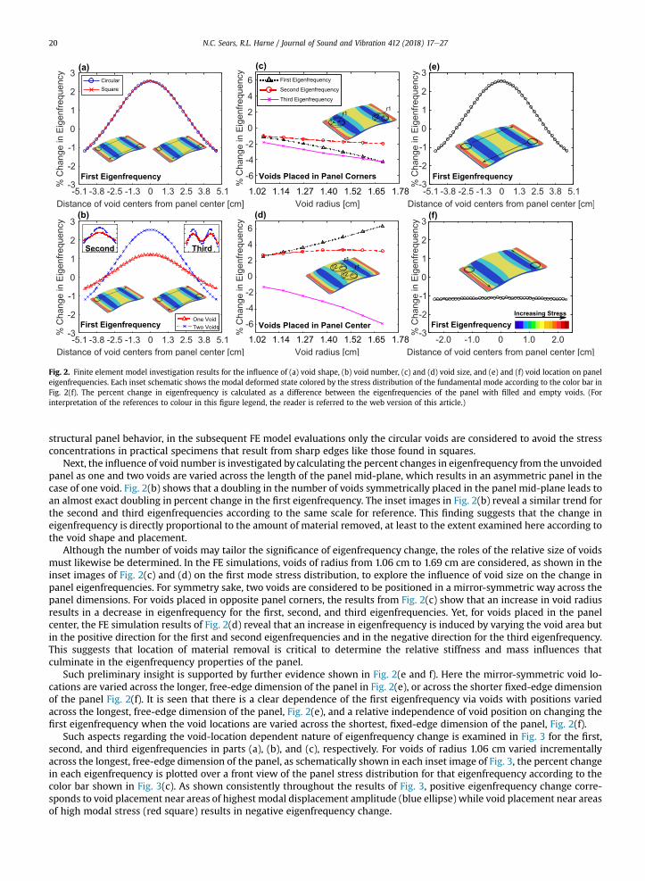
Fig. 2. Finite element model investigation results for the influence of (a) void shape, (b) void number, (c) and (d) void size, and (e) and (f) void location on paneleigenfrequencies. Each inset schematic shows the modal deformed state colored by the stress distribution of the fundamental mode according to the color bar inFig. 2(f). The percent change in eigenfrequency is calculated as a difference between the eigenfrequencies of the panel with filled and empty voids. (Forinterpretation of the references to colour in this figure legend, the reader is referred to the web version of this article.)
N.C. Sears, R.L. Harne / Journal of Sound and Vibration 412 (2018) 17e2720
structural panel behavior, in the subsequent FE model evaluations only the circular voids are considered to avoid the stressconcentrations in practical specimens that result from sharp edges like those found in squares.
Next, the influence of void number is investigated by calculating the percent changes in eigenfrequency from the unvoidedpanel as one and two voids are varied across the length of the panel mid-plane, which results in an asymmetric panel in thecase of one void. Fig. 2(b) shows that a doubling in the number of voids symmetrically placed in the panel mid-plane leads toan almost exact doubling in percent change in the first eigenfrequency. The inset images in Fig. 2(b) reveal a similar trend forthe second and third eigenfrequencies according to the same scale for reference. This finding suggests that the change ineigenfrequency is directly proportional to the amount of material removed, at least to the extent examined here according tothe void shape and placement.
Although the number of voids may tailor the significance of eigenfrequency change, the roles of the relative size of voidsmust likewise be determined. In the FE simulations, voids of radius from 1.06 cm to 1.69 cm are considered, as shown in theinset images of Fig. 2(c) and (d) on the first mode stress distribution, to explore the influence of void size on the change inpanel eigenfrequencies. For symmetry sake, two voids are considered to be positioned in a mirror-symmetric way across thepanel dimensions. For voids placed in opposite panel corners, the results from Fig. 2(c) show that an increase in void radiusresults in a decrease in eigenfrequency for the first, second, and third eigenfrequencies. Yet, for voids placed in the panelcenter, the FE simulation results of Fig. 2(d) reveal that an increase in eigenfrequency is induced by varying the void area butin the positive direction for the first and second eigenfrequencies and in the negative direction for the third eigenfrequency.This suggests that location of material removal is critical to determine the relative stiffness and mass influences thatculminate in the eigenfrequency properties of the panel.
Such preliminary insight is supported by further evidence shown in Fig. 2(e and f). Here the mirror-symmetric void lo-cations are varied across the longer, free-edge dimension of the panel in Fig. 2(e), or across the shorter fixed-edge dimensionof the panel Fig. 2(f). It is seen that there is a clear dependence of the first eigenfrequency via voids with positions variedacross the longest, free-edge dimension of the panel, Fig. 2(e), and a relative independence of void position on changing thefirst eigenfrequency when the void locations are varied across the shortest, fixed-edge dimension of the panel, Fig. 2(f).
Such aspects regarding the void-location dependent nature of eigenfrequency change is examined in Fig. 3 for the first,second, and third eigenfrequencies in parts (a), (b), and (c), respectively. For voids of radius 1.06 cm varied incrementallyacross the longest, free-edge dimension of the panel, as schematically shown in each inset image of Fig. 3, the percent changein each eigenfrequency is plotted over a front view of the panel stress distribution for that eigenfrequency according to thecolor bar shown in Fig. 3(c). As shown consistently throughout the results of Fig. 3, positive eigenfrequency change corre-sponds to void placement near areas of highest modal displacement amplitude (blue ellipse) while void placement near areasof high modal stress (red square) results in negative eigenfrequency change.

Fig. 3. Finite element model investigation results of the influence of void location on the (a) first, (b) second, and (c) third eigenfrequencies of the structural panelFE model plotted over front view of the modal stress distribution. The percent change in eigenfrequency is calculated as a difference between the eigen-frequencies of the panel with filled and empty voids.
N.C. Sears, R.L. Harne / Journal of Sound and Vibration 412 (2018) 17e27 21
The finite element model investigations show that although void shape does not play a significant role in changing theeigenfrequencies of the panel, void location determines the sign of eigenfrequency change while void size and numberamplify the eigenfrequency variation, likely due to the amount of material removal. These findings suggest that structuralpanels may be designed such that material transitions between voids placed in locations of high modal stress and highmodaldisplacement can occur for a targeted low order mode to be tuned. Specifically, voids at locations of largemodal displacementare seen to result in an increase in the eigenfrequency while voids at locations of large modal stress cause a reduction ineigenfrequency. By using such combination of voids andmaterial transition between them, eigenfrequency variation betweenmaximum and minimum values is induced. For example as schematically shown in Fig. 4(a), a panel designed to adapt thefirst eigenfrequency may have a set of voids placed on and/or near the antinode of the first eigenmode and another set ofvoids near to the fixed edge where stress for the first mode is maximized. Under the assumptions of the FE model for amaterial transition between such void sets, with radius 1.69 cm, notable changes in eigenfrequency that leverage strategicvoid location may be realized. As shown in Fig. 4(b), eigenfrequency changes of 10.0, 5.0, and 7.4% are ideally possible for thefirst, second, and third eigenfrequencies, respectively, with respect to the eigenfrequencies of the unvoided panel using thisapproach.
3. Experimental validation
This section describes experimental efforts undertaken to validate the finite element model and explore opportunities formaterial transitions through internal voids to tailor the structural dynamics of panels. Following a description of fabricationmethods for specimens considered, measurements taken with free-free and fixed-free panels are reported and discussed.
3.1. Specimen fabrication
The panel specimens are fabricated by bonding two pieces of acrylic together. Each panel piece represents half of aspecimen, and, as appropriate, each panel half includes voids engraved at one-half of the depth required to achieve the totalvoid thickness once the panel halves are bonded together. Transparent acrylic sheets (McMaster-Carr, 8560K171) are used.This material is chosen based on the capabilities of the laser cutter (Full Spectrum LASER H-Series 20x12 Desktop CO2 Laser)to cut specimens out of acrylic stock and to engrave voids, as schematically shown in Fig. 5(a and b). For all specimens, solventbonding (TAPAcrylic) is utilized to securely and completely bond the specimen halves together, Fig. 5(c and d). The specimensare 13.7 by 8.5 cm2 in span, and 3.2 mm in thickness. Due to clamping boundary conditions required for the fixed-free panelevaluations, the side fixed with the clamps must extend beyond the clampmounting point, which necessitates the additionallength on the 13.7 cm side. Thus, for the fixed-free panel experiments, the resulting panel extending beyond the clamps hasdimensions of 12.7 by 8.5 cm2 in span and 3.2mm in thickness, in agreement with the FEmodel composition for the fixed-freepanel. Experiments conducted with the panel in a free-free boundary condition have panel dimensions 13.7 by 8.5 cm2 inspan and 3.2 mm in thickness. As shown in Fig. 5(e)-(h), the specimens fabricated include panels with (e) no voids, (f) voidsplaced on a shared displacement node of the first, second, and third modes, (g) voids placed on the anti-node of the thirdmode displacement, and (h) voids placed on the shared anti-node of the first and second mode displacement. For clarity, thespecimen without voids, shown in Fig. 5(e), is also fabricated by solvent bonding two sheets together in the method used forthe specimens with voids. In this way, all specimens evaluated include the similar bonding-related influences upon themechanical properties and structural dynamics.

Fig. 4. Shown on (a) the stress distribution of the first mode, voids placed in areas of both high modal stress and highest amplitude modal displacement can beused together such that a material transition between such voids could occur. This material transition would constitute a percent eigenfrequency change betweenmaximum positive and negative percent eigenfrequency changes with respect to the original eigenfrequencies, with total changes shown in (b).
Fig. 5. Fabricating the specimens constitutes (a) cutting the specimens out of acrylic stock with a laser cutter, (b) engraving half of each void (if present) into asingle piece of acrylic with a laser cutter, (c) bonding the two pieces of acrylic together with acrylic cement to constitute (d) the final specimen. The fabricatedspecimens are shown in (e), (f), (g), and (h).
N.C. Sears, R.L. Harne / Journal of Sound and Vibration 412 (2018) 17e2722
3.2. Impact hammer experiments
Impact hammer experiments are performed on free-free panel specimens as a first step to validate the FE model. Com-parisons between experimental and FE model mode shapes for the unvoided specimen and eigenfrequencies for all speci-mens are used for this validation. Using the FE model infrastructure of this research, it is computed that free-free panels havefirst, second, and third eigenfrequencies of 285, 324, and 689 Hz, respectively.
In the experiments, specimens are suspended by fishing line as seen in Fig. 6(a). Then, a modal impact hammer (PCB086C02) strikes the specimens at nine different locations, while acceleration is measured with a mini-accelerometer (PCBU352B22) at one location. These signals are then processed (LMS SCADAS Mobile SCM01) to extract the mode shapes andcorresponding eigenfrequencies. The measured mode shapes of each panel specimen are correlated to the mode shapespredicted by the FE model to serve as preliminary model validation. The mode shapes of the first three eigenfrequencies areshown in Fig. 6(beg) for the specimenwithout voids by displacement according to the color bar in Fig. 6(c). Clear agreement isobserved comparing FE model predictions and experimental results for the panel mode shapes. Similar agreement is seenbetween the mode shapes measured and predicted for specimens with voids, which are not presented here for brevity sakebecause the voids do not greatly change the modal deformations for these lowest order eigenmodes.
On the other hand, voids do tailor the eigenfrequencies of the lowest order modes from the case of the unvoided panel.Looking closely at the eigenfrequency characteristics of all of the panel specimens evaluated with free-free boundary con-ditions, Fig. 7 displays a comparison between the predicted and measured eigenfrequencies for (a) the unvoided specimen,and for the specimens with voids placed on (b) a node of the first, second, and third mode, (c) the antinodes of the third mode,and (d) the antinodes of the first and second mode. The FE model predictions are closer to experimental data in Fig. 7(a) forthe unvoided specimen more so than compared to Fig. 7(b), (c), and (d) for the voided specimens. Yet, in all cases, themeasurements of eigenfrequency are equal to or slightly less than those values determined from themodel. This suggests that

Fig. 6. (a) The experimental setup with free-free panel specimens suspended by fishing line, hit in nine different locations indicated by cyan stars, with ac-celeration measured by an accelerometer placed on the specimen. LMS software is then used to correlate experimental mode shapes for the (b) first, (d) second,and (f) third mode shapes with the (c) first, (e) second, and (g) third mode shapes predicted by the finite element model for the unvoided specimen. (Forinterpretation of the references to colour in this figure legend, the reader is referred to the web version of this article.)
Fig. 7. FE model predictions (yellow bars) and experimental results (blue bars) for the eigenfrequencies of (a) the unvoided specimen, (b) the specimen withvoids placed on a node of the first, second, and third mode, (c) the specimen with voids placed on the third mode antinodes, and (d) the specimen with voidsplaced on the first and second mode antinodes. (For interpretation of the references to colour in this figure legend, the reader is referred to the web version of thisarticle.)
N.C. Sears, R.L. Harne / Journal of Sound and Vibration 412 (2018) 17e27 23
a softening mechanism in the solvent bonding process uniformly influences the eigenfrequencies of the experimentalspecimens. Despite such uniform reduction in the eigenfrequency changes observed experimentally than those predicted bythe model, the overall agreement between modeled and experimental results serves as validation to the premise of voidinclusions to tailor the dynamic properties of the panels.
3.3. Random excitation shaker experiments
Random excitation experiments are performed on fixed-free panel specimens to characterize the frequency responseadaptation via material redistributions within the panel specimens.

Fig. 8. (a) Random excitation experiment schematic, (b) comparison between experimental results (blue bars) with FE model predictions of the eigenfrequenciesof the unvoided specimen for pinned-free (red bars) and fixed-free (yellow bars) boundary conditions, and (c) the frequency response transfer function for each ofthe panel specimens. (For interpretation of the references to colour in this figure legend, the reader is referred to the web version of this article.)
N.C. Sears, R.L. Harne / Journal of Sound and Vibration 412 (2018) 17e2724
A schematic of the experimental setup is shown in Fig. 8(a). A vibration controller (Vibration Research VR9500) provides awhite noise signal to a power amplifier (LabWorks PA-141) that drives the electrodynamic shaker (LabWorks LT-140-110) towhich specimens are fixed. An accelerometer (PCB 352C33) is placed on the shaker for control purposes, while three ac-celerometers (PCB 352A24) are placed on the panel specimens to measure the output panel acceleration. Accelerometerplacements on the panels are selected to best measure the lowest order modes according to the modal displacementamplitude anticipated from the FE model studies. For the random excitation experiments, the panel specimens undergo baseacceleration excitationwith white noise filtered from 50 to 2000 Hz. Data is acquired at a sampling frequency of 16384 Hz foran individual experiment time of 1 min. The frequency response transfer function is then computed respecting the outputglobal acceleration to the input base acceleration.
The eigenfrequencies measured for the fixed-free panels and the FE model predictions are compared in Fig. 8(b). Becauseof additional compliance introduced in the experimental realization of fixed boundary edges on the softer acrylic panelmaterial, it is observed that the boundary conditions are more accurately reproduced in the FE model via pinned edges on theside that are ideally “fixed”. Thus, the FE model for pinned-free boundaries is more comparable to the fixed-free conditionsrealized in the laboratory. Indeed, as seen in Fig. 8(b), the eigenfrequencies of the pinned-free unvoided specimen (red bars)show stronger resemblance to the experimental data (blue bars) than the fixed-free specimen (yellow bars) for the first andthird eigenfrequencies. In contrast, the second eigenfrequency in the FE model shows greater deviation from experimentaldata for the pinned-free specimen compared to the fixed-free specimen. This is believed to be due to twisting motion of thesecond mode, as seen in Fig. 3(b), which may more substantially resist the clamping setup. Because results of the impacthammer evaluations using free-free specimens agree well with FE model predictions, it is apparent that the experimentalrealization of the fixed-edge boundary conditions for the acrylic specimens is challenging. On the other hand, the variation infrequency response shown in Fig. 8(c) exemplifies that the natural frequencies may be appreciably altered by introducing thevoids in the panels. In the case of the void placement on the first and second mode antinodes (red dashed curve), the secondmode natural frequency is seen to shift by almost 18% when compared to the panel specimen without voids (black dottedcurve).
To explore the opportunity for controlling these dynamic properties via real-time material redistribution, the motivatingspirit of this research is harnessed via on-demand fluid flow into and out of the panels with fixed-free boundaries while theshaker provides a random excitation. During this time, the voids are filled using syringes connected to tubes that access thevoids. Each void is connected to two tubes, one for the injection of blue colored water and one for air relief. The slow fluidinjection is stopped when water begins to escape through the air relief tube. The filling procedure is undertaken slowlyenough such that about 90 s elapse from the time of no fluid fill to the time of full fluid fill, which is a filling rate slightlygreater than 1% void volume per second. This slow fluid fill procedure ensures that near-steady-state conditions are achieved

Fig. 9. Random excitation experiment results shown for the voided specimens with (a) empty and (b) filled voids placed on the antinodes of vibration of the thirdeigenfrequency with (c) the frequency response shift shown as a result of a filled to empty void transition. Additionally, depicted here are (d) empty and (e) filledvoids placed on a node of vibration of the first, second, and third eigenfrequency with (f) the frequency response shift shown as a result of a filled to empty voidtransition. Shifts in frequency response are plotted according to the FE model simulations in which the panel undergoes a material transition from filled (dottedblack line) to empty (solid red line) voids. (For interpretation of the references to colour in this figure legend, the reader is referred to the web version of thisarticle.)
N.C. Sears, R.L. Harne / Journal of Sound and Vibration 412 (2018) 17e27 25
over several seconds of time duration in order to compute the broadband frequency response. In order to replicate the filled toempty material transition used in the FE model, the frequency response transfer function is shown for two of the voidedspecimens as a difference between filled and empty voids, as seen in Fig. 9(c,f).
Fig. 9(c) shows that, for the specimen with voids placed on the antinodes of vibration of the third mode, the thirdeigenfrequency at 640 Hz shifts by 18 Hz, or 2.74% of its original value, with a þ1.02 dB change in its amplitude response.Considering the FE model results, this experimental trend is in agreement with the predicted decrease in third eigenfre-quency by material removal from the antinodes of vibration for the third mode. Measurements presented in Fig. 9(f) showthat for the specimen with voids placed on the nodes of vibration of the first, second, and third eigenfrequencies, theeigenfrequencies shift by �1 Hz, 0 Hz, and þ10 Hz with corresponding �0.58 dB, �0.05 dB, and þ1.16 dB changes inamplitude, respectively. Excepting the lack of change for the second eigenfrequency, these decreases in eigenfrequency arelikewise in agreement with the FE model results. On the other hand, the significance of the measured eigenfrequency shiftsare not as great as those predicted in the FE simulations. This may be explained by the attachment of the fluid-flow tubes inthe axis of panel out-of-plane deflection that may substantially modify the structural dynamics by contributing undesiredstiffness and mass to impede the free out-of-plane deformation. These influences may counteract the influences of the fluidfill via microvascular channels towards tailoring the overall structural dynamics at the mid-plane, and encourage animplementation of mid-plane level microvascular channels as ideally envisioned in Fig. 1. The coupling of the fluid-flow tubesused in experiments here may consequently exert similar influences observed for cables that interact with the dynamics ofstructures to which the cables are attached [39,40]. Nevertheless, the trends of the experimental results of on-demand fluiddelivery are supported by the FE model findings to exemplify the concept of leveraging internal fluid-based material re-distributions to adapt the dynamic properties of structural panels for vibration control practices.
4. Conclusions
In this research, passive adaptation of structural panel dynamic properties is examined via the transmission of material inand out of voids at the mid-plane of the panel. From computational and experimental studies, it is found that, with respect toan unvoided panel, material voids in areas of higher modal displacement lead to an increase in eigenfrequency while materialvoids positioned in areas of higher stress correspond to a decrease in eigenfrequency. These effects are magnified using largervoid sizes and a greater number of identical voids, to the extent and number considered here. The FE model suggests that bytransferring material between strategically placed voids, an eigenfrequency change between positive and negative values,

N.C. Sears, R.L. Harne / Journal of Sound and Vibration 412 (2018) 17e2726
with respect to those of the panel without voids, may be as great as 10.0, 5.0, and 7.4% for the first, second, and third modes,respectively. Experiments are undertaken to provide model validations and for exploratory purposes including to probe howfluid flow into and out of the panel influences the dynamic response in real time. The experiments also illuminate practicalchallenges and opportunities for material redistribution that passively adapts the dynamic properties of panels, for instancethe possibility of using denser fluids, such as liquid metals [33], that may more substantially tailor the vibration character-istics of the structures. Additionally, in a manner similar to how free sliding masses may be redistributed via resonantphenomena to tune structural dynamics [20,21], future investigations may study the ability of fluid to redistribute itselfthroughout the embedded voids in panel systems to similarly tune the panel dynamics. These efforts identify strategies forfuture FE model improvements and exemplify the opportunities for leveraging microvascular channels within structuralpanels to tune dynamic properties using internal and non-obtrusive elements for vibration control.
Acknowledgements
The authors acknowledge helpful conversations about the motivations of this research with Dr. Jeff Baur of the Air ForceResearch Laboratory and Dr. Darren Hartl of the Texas A&M University. The authors also thank Dr. Jason Dreyer of The OhioState University (OSU) for assistance during the impact hammer experiments. R.L.H. acknowledges start-up funds from theDepartment of Mechanical and Aerospace Engineering at The Ohio State University (OSU). N.C.S. acknowledges support fromthe OSU College of Engineering Honors Research Scholarship.
References
[1] D.J. Ewins, Control of vibration and resonance in aero engines and rotating machinery - an overview, Int. J. Press. Vessels Pip. 87 (2009) 504e510.[2] E. Poursaeidi, A. Babaei, M.R. Mohammadi Arhani, M. Arablu, Effects of natural frequencies on the failure of R1 compressor blades, Eng. Fail. Anal. 25
(2012) 304e315.[3] S.K. Bhaumik, M. Sujata, M.A. Venkataswamy, Fatigue failure of aircraft components, Eng. Fail. Anal. 15 (6) (2008) 675e694.[4] M. Aykan, M. Celik, Vibration fatigue analysis and multi-axial effect in testing of aerospace structures, Mech. Syst. Signal Process. 23 (3) (2009)
897e907.[5] J.F. Wilby, F.L. Gloyna, Vibration measurements of an airplane fuselage structure, J. Sound Vib. 23 (1972) 443e446.[6] I. Holehouse, Sonic fatigue of aircraft structures due to jet engine fan noise, J. Sound Vib. 17 (1971) 287e298.[7] T. Bailey, J.E. Hubbard, Distributed piezoelectric-polymer active vibration control of a cantilever beam, AIAA J. 8 (1985) 605e611.[8] G. Ferrari, M. Amabili, Active vibration control of a sandwich plate by non-collocated positive position feedback, J. Sound Vib. 342 (2015) 44e56.[9] C.R. Fuller, S.D. Snyder, C.H. Hansen, R.J. Silcox, Active control of interior noise in model aircraft fuselages using piezoceramic actuators, AIAA J. 30
(1992) 2613e2617.[10] E. Bianchi, P. Gardonio, S.J. Elliot, Smart panel with multiple decentralized units for the control of sound transmission. part I: theoretical predictions, J.
Sound Vib. 274 (2004) 163e192.[11] J.P. Carneal, C.R. Fuller, An analytical and experimental investigation of active structural acoustic control of noise transmission through double panel
systems, J. Sound Vib. 272 (2004) 749e771.[12] B. Aloufi, K. Behdinan, J. Zu, Vibro-acoustic model of an active aircraft cabin window, J. Sound Vib. 398 (2017) 1e27.[13] R. Boulandet, M. Michau, P. Micheau, A. Berry, Aircraft panel with sensorless active sound power reduction capabilities through virtual mechanical
impedance, J. Sound Vib. 361 (2016) 2e19.[14] X. Ma, K. Chen, S. Ding, H. Yu, Physical mechanisms of active control of sound transmission through rib stiffened double-panel structure, J. Sound Vib.
371 (2016) 2e18.[15] D. Casagrande, P. Gardonio, M. Zilletti, Smart panel with time-varying shunted piezoelectric patch absorbers for broadband vibration control, J. Sound
Vib. 400 (2017) 288e304.[16] K.O. Prakah-Asante, K.C. Craig, The application of multi-channel design methods for vibration control of an active structure, Smart Mater. Struct. 3
(1994) 329e343.[17] C. Zhang, J. Ou, Modeling and dynamical performance of the electromagnetic mass driver system for structural vibration control, Eng. Struct. 82 (2015)
93e103.[18] Y. Wang, M. Masourni, M. Gaucher-Petitdemange, Damping analysis of a flexible cantilever beam containing an internal fluid channel: experiment,
modeling and analysis, J. Sound Vib. 340 (2015) 331e342.[19] T.P. Burg, J.E. Sader, S.R. Manalis, Nonmonotonic energy dissipation in microfluidic resonators, Phys. Rev. Lett. 102 (22) (2009) 1e4.[20] L.M. Miller, P. Pillatsch, E. Halvorsen, P.K. Wright, E.M. Yeatman, A.S. Holmes, Experimental passive self-tuning behavior of a beam resonator with
sliding proof mass, J. Sound Vib. 332 (2013) 7142e7152.[21] V.I. Babitsky, A.M. Veprik, Damping of beam forced vibration by a moving washer, J. Sound Vib. 166 (1) (1993) 77e85.[22] J.J. Thomsen, Vibration suppression by using self-arranging mass: effects of adding restoring force, J. Sound Vib. 197 (1996) 403e425.[23] B. Zhu, C.D. Rahn, C.E. Bakis, Fluiduc flexible matrix composite vibration absorber for a cantilever beam, J. Vib. Acoust. 137 (2015), 021005.[24] L.H. Scarborough III, C.D. Rahn, E.C. Smith, Fluidic composite tunable vibration isolators, J. Vib. Acoust. 134 (2012) 1e7.[25] P.R. Cunningham, R.G. White, Dynamic response of doubly curved honeycomb sandwich panels to random acoustic excitation, J. Sound Vib. 264 (2003)
579e603.[26] M.P. Arunkumar, M. Jagadeesh, J. Pitchaimani, K.V. Gangadharan, M.C. Lenin Babu, Sound radiation and transmission loss characteristics of a hon-
eycomb sandwich panel with composite facings: effect of inherent material damping, J. Sound Vib. 383 (2016) 221e232.[27] C.V.R. Reddy, N. Ganesan, B.V.A. Rao, Response of clamped sandwich panels with viscoelastic core under random acoustic excitation, J. Sound Vib. 75
(1981) 481e494.[28] C.J. Cameron, E.L. Nordgren, P. Wennhage, P. Goransson, On the balancing of structural and acoustic performance of a sandwich panel based on to-
pology, property, and size optimization, J. Sound Vib. 333 (2014) 2677e2698.[29] J.S. Bolton, N.M. Shiau, Y.J. Kang, Sound transmission through multi-panel structures lined with elastic porous materials, J. Sound Vib. 191 (1996)
317e347.[30] Y. Liu, Sound transmission through triple-panel structures lined with poroelastic materials, J. Sound Vib. 339 (2015) 376e395.[31] C. Guigou, C.R. Fuller, Control of aircraft interior broadband noise with foam-pvdf smart skin, J. Sound Vib. 220 (1999) 541e557.[32] A.A. Mana, V.R. Sonti, Sound radiation from a perforated panel set in a baffle with a different perforation ratio, J. Sound Vib. 372 (2016) 317e341.[33] D.J. Hartl, G.J. Frank, G.H. Huff, J.W. Baur, A liquid metal-based structurally embedded vascular antenna: I. concept and multiphysical modeling, Smart
Mater. Struct. 26 (2016) 1e15.

N.C. Sears, R.L. Harne / Journal of Sound and Vibration 412 (2018) 17e27 27
[34] D.J. Hartl, G.H. Huff, H. Pan, L. Smith, R.L. Bradford, G.J. Frank, J.W. Baur, Analysis and characterization of structurally embedded vascular antennas usingliquid metals, in: SPIE 9803, Las Vegas, Nevada, 2016, pp. 1e9.
[35] K.S. Toohey, N.R. Sottos, J.A. Lewis, J.S. Moore, S.R. White, Self-healing materials with microvascular networks, Nat. Mater. 6 (2007) 581e585.[36] C.J. Hansen, W. Wu, K.S. Toohey, N.R. Sottos, S.R. White, J.A. Lewis, Self-healing materials with interpenetrating microvascular networks, Adv. Mater. 21
(2009) 4143e4147.[37] R.C.R. Gergely, S.J. Pety, B.P. Krull, J.F. Patrick, T.Q. Doan, A.M. Coppola, P.R. Thakre, N.R. Sottos, J.S. Moore, S.R. White, Multidimensional vascularized
polymers using degradable sacrificial templates, Adv. Funct. Mater. (2015) 1043e1052.[38] S. Soghrati, P.R. Thakre, S.R. White, N.R. Sottos, P.H. Geubelle, Computational modeling and design of actively-cooled microvascular materials, Int. J.
Heat Mass Transf. 55 (2012) 5309e5321.[39] D.M. Coombs, J.C. Goodding, V. Babu�ska, E.V. Ardelean, L.M. Robertson, S.A. Lane, Dynamic modeling and experimental validation of a cable-loaded
panel, J. Spacecr. Rockets 48 (2011) 958e973.[40] K.S. Spak, G.S. Agnes, D.J. Inman, Modeling vibration response and damping of cables and cabled structures, J. Sound Vib. 336 (2015) 240e256.

![Journal of Sound and Vibration - Lakehead Universityflash.lakeheadu.ca/~kliu/JSV_2010_1.pdf · Journal of Sound and Vibration 329 (2010) 1254–1273. were used in [6] to improve vehicle](https://static.fdocuments.us/doc/165x107/5f7df43fb84a72049b17ec49/journal-of-sound-and-vibration-lakehead-kliujsv20101pdf-journal-of-sound.jpg)