
VIBRATION TRANSMISSION THROUGH AN … and...Journal of Sound and
29
Journal of Sound and < ibration (2001) 248(5), 925 } 953 doi:10.1006/jsvi.2001.3852, available online at http://www.idealibrary.com on VIBRATION TRANSMISSION THROUGH AN ISOLATOR MODELLED BY CONTINUOUS SYSTEM THEORY S. KIM AND R. SINGH Acoustics and Dynamics ¸aboratory, Department of Mechanical Engineering and ¹he Center for Automotive Research, ¹ he Ohio State ;niversity, Columbus, OH 43210-1107, ;.S.A. E-mail: singh.3@osu.edu (Received 19 February 2001, and in ,nal form 15 June 2001) This article focuses on the #exural motion of an elastomeric isolator but the longitudinal motion is also considered. The continuous system theory is used to describe mobility or sti!ness characteristics and power-based vibration isolation measures. The scope of this study is limited to the frequency domain analysis of a linear time-invariant (LTI) system with a single isolator that is placed between a rigid body and a "nite or in"nite beam receiver. The upper limit of the frequency range is 4 kHz. Two types of solutions to the Timoshenko beam for a rubber material are critically examined, and the Timoshenko and Euler beam solutions are compared for vibration power measures. Our analysis shows that the shear deformation and rotary inertia must be considered in order to properly describe a thick isolator that e!ectively transmits #exural motions at higher frequencies. The shear deformation e!ect is, however, found to be more pronounced as evaluated by the power-based vibration isolation measures at higher frequencies. Further, the roles of isolator parameters such as the static sti!ness ratios, shape factors and material properties are investigated. The continuous system theory clearly accounts for the cross-axis coupling terms and it may be further utilized for optimizing vibration isolation schemes over a wide range of frequencies. ( 2001 Academic Press 1. INTRODUCTION Vibration isolators are often characterized as discrete elastic elements, with or without viscous or hysteritic damping [1}4]. The compressional sti!ness term is typically used to develop isolation system models [2}4] though the transverse (shear) and rotational components are also sometimes speci"ed or included [5}7]. Additionally, at higher frequencies, inertial or standing wave e!ects occur within the isolator [8, 9]. Nonetheless, the isolators are still modelled by many researchers in terms of spectrally invariant discrete sti!ness elements without any cross-axis coupling terms [5}7]. Such descriptions are clearly inadequate at higher frequencies. Consequently, one must adopt the distributed parameter approach. It is the main focus of this article. Only a few articles have examined the elastomeric devices using the continuous vibration system theories [10}15]. For example, the longitudinal sti!ness of an isolator has been described by the wave equation to characterize the material property of an isolator [13]. Also, rubber-like material has been modelled using the wave closure relationship [14]. The Euler beam theory has been adopted to describe the #exural motions of a mount for an active vibration control system [10, 11] and to characterize an isolator [12]. However, no prior article has examined the shear deformation and rotary inertia e!ects of an isolator. Further, the in#uence of component parameters on the behavior of an isolation system has 0022-460X/01/500925#29 $35.00/0 ( 2001 Academic Press
Transcript of VIBRATION TRANSMISSION THROUGH AN … and...Journal of Sound and
Journal of Sound and <ibration (2001) 248(5), 925}953doi:10.1006/jsvi.2001.3852, available online at http://www.idealibrary.com on
VIBRATION TRANSMISSION THROUGH AN ISOLATORMODELLED BY CONTINUOUS SYSTEM THEORY
S. KIM AND R. SINGH
Acoustics and Dynamics ¸aboratory, Department of Mechanical Engineering and ¹he Center forAutomotive Research, ¹he Ohio State ;niversity, Columbus, OH 43210-1107, ;.S.A.
E-mail: [email protected]
(Received 19 February 2001, and in ,nal form 15 June 2001)
This article focuses on the #exural motion of an elastomeric isolator but the longitudinalmotion is also considered. The continuous system theory is used to describe mobility orsti!ness characteristics and power-based vibration isolation measures. The scope of thisstudy is limited to the frequency domain analysis of a linear time-invariant (LTI) system witha single isolator that is placed between a rigid body and a "nite or in"nite beam receiver. Theupper limit of the frequency range is 4 kHz. Two types of solutions to the Timoshenko beamfor a rubber material are critically examined, and the Timoshenko and Euler beam solutionsare compared for vibration power measures. Our analysis shows that the shear deformationand rotary inertia must be considered in order to properly describe a thick isolator thate!ectively transmits #exural motions at higher frequencies. The shear deformation e!ect is,however, found to be more pronounced as evaluated by the power-based vibration isolationmeasures at higher frequencies. Further, the roles of isolator parameters such as the staticsti!ness ratios, shape factors and material properties are investigated. The continuoussystem theory clearly accounts for the cross-axis coupling terms and it may be furtherutilized for optimizing vibration isolation schemes over a wide range of frequencies.
( 2001 Academic Press
1. INTRODUCTION
Vibration isolators are often characterized as discrete elastic elements, with or withoutviscous or hysteritic damping [1}4]. The compressional sti!ness term is typically used todevelop isolation system models [2}4] though the transverse (shear) and rotationalcomponents are also sometimes speci"ed or included [5}7]. Additionally, at higherfrequencies, inertial or standing wave e!ects occur within the isolator [8, 9]. Nonetheless,the isolators are still modelled by many researchers in terms of spectrally invariant discretesti!ness elements without any cross-axis coupling terms [5}7]. Such descriptions are clearlyinadequate at higher frequencies. Consequently, one must adopt the distributed parameterapproach. It is the main focus of this article.
Only a few articles have examined the elastomeric devices using the continuous vibrationsystem theories [10}15]. For example, the longitudinal sti!ness of an isolator has beendescribed by the wave equation to characterize the material property of an isolator [13].Also, rubber-like material has been modelled using the wave closure relationship [14]. TheEuler beam theory has been adopted to describe the #exural motions of a mount for anactive vibration control system [10, 11] and to characterize an isolator [12]. However, noprior article has examined the shear deformation and rotary inertia e!ects of an isolator.Further, the in#uence of component parameters on the behavior of an isolation system has
0022-460X/01/500925#29 $35.00/0 ( 2001 Academic Press
926 S. KIM AND R. SINGH
been investigated using a standing wave description in the longitudinal direction anda static sti!ness term in the #exural direction [14]. Yet, the frequency-dependentcharacteristics of an isolator have not been considered in the previous isolation studies. Thisarticle proposes to overcome this particular void in the literature.
2. PROBLEM FORMULATION
Vibration transmitted via multi-dimensional motions of an isolator is conceptuallyshown in Figure 1 in the context of source, path (isolator) and receiver. A rigid body isemployed for the source and the receiver is modelled using two alternate formulations: anin"nite beam and then a "nite beam with "xed boundary conditions. The analysis focuseson the #exural motion of the isolator but the longitudinal motion is also considered.Though both are assumed to be uncoupled within the isolator, coupling will arise because ofthe receiver dynamics. Harmonic force and moment excitations are applied at the masscenter of source. The scope of this study is strictly limited to the frequency domain analysisof a linear time-invariant (LTI) system with a single isolator that is placed between a rigidbody and #exible receiver. Complicating e!ects such as isolator pre-load, temperaturedependence and the like are not considered. Primary objectives of this study are as follows.(1) Develop the frequency response characteristics (mobility or sti!ness) of an isolator basedon the continuous system theory that includes Timoshenko beam (in the transversex direction) and the longitudinal (y) wave equation formulation. In particular, criticallyexamine the two types of solutions to the Timoshenko beam for a cylindrical rubbermaterial. (2) Compare the Timoshenko and Euler beam solutions for the e!ects of sheardeformation and rotary inertia of an isolator on vibration power attenuation measures. (3)Investigate the role of isolator parameters such as the static sti!ness ratios, shape factorsand material properties on isolation measures over a broad range of frequencies.
3. FLEXURAL MODEL OF ISOLATOR USING TIMOSHENKO BEAM THEORY
3.1. MOBILITIES OF A FINITE TIMOSHENKO BEAM
The classical Timoshenko beam theory that describes the e!ects of shear deformationand rotary inertia has been well studied by many researchers [4, 16}18]. The literatureshows that there are two types of solution and two modal functions that exist at highfrequencies [4, 16]. However, the high-frequency solution has been ignored by many sincethis phenomenon has been believed to occur only at extremely high frequencies [4]. Onlya few studies have been conducted to examine the dispersion and spectrum relations of theTimoshenko beam structure at high frequencies [17, 18]. In our study, we examine this issueand the harmonic response of an elastomeric beam with free boundary conditions. It isassumed that the shear modulus (G) is very low, which is true for a rubber-like material.Further, the characteristic mobilities are obtained for a semi-in"nite beam. The governingequation for an unforced and undamped Timoshenko beam (in #exure) is expressed asfollows where E is the Young's modulus, I
Sis the area moment of inertia, S is the section
area, o is the mass density and i is the shear constant [4, 16]. Also, refer to Appendix A forthe identi"cation of symbols.
EIS
L4XM (y, t)
Ly4#oS
L2XM (y, t)
Lt2!CoI
S#EI
S
oiGD
L4XM (y, t)
Lt2Ly2#oI
S
oiG
L4XM (y, t)
Lt4"0. (1)
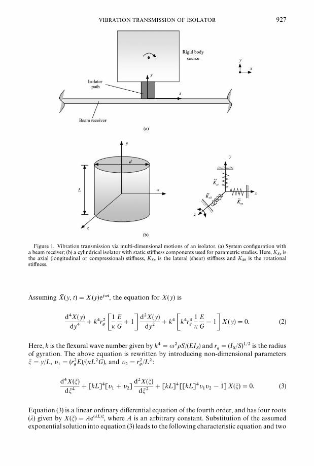
Figure 1. Vibration transmission via multi-dimensional motions of an isolator. (a) System con"guration witha beam receiver; (b) a cylindrical isolator with static sti!ness components used for parametric studies. Here, K
Syis
the axial (longitudinal or compressional) sti!ness, KSx
is the lateral (shear) sti!ness and KSh is the rotational
sti!ness.
VIBRATION TRANSMISSION OF ISOLATOR 927
Assuming XM (y, t)"X (y)e+ut, the equation for X(y) is
d4X(y)
dy4#k4r2
g C1
iE
G#1D
d2X(y)
dy2#k4 Ck4r4
g
1
iE
G!1D X(y)"0. (2)
Here, k is the #exural wave number given by k4"u2oS/(EIS) and r
g"(I
S/S)1@2 is the radius
of gyration. The above equation is rewritten by introducing non-dimensional parametersm"y/¸, t
1"(r2
gE)/(i¸2G), and t
2"r2
g/¸2 :
d4X(m)
dm4#[k¸]4[t
1#t
2]
d2X(m)
dm2#[k¸]4[[k¸]4t
1t2!1] X(m)"0. (3)
Equation (3) is a linear ordinary di!erential equation of the fourth order, and has four roots(j) given by X(m)"Ae(jL)m, where A is an arbitrary constant. Substitution of the assumedexponential solution into equation (3) leads to the following characteristic equation and two

928 S. KIM AND R. SINGH
categories of roots [16]:
(j¸)4#[k¸]4[t1#t
2](j¸)2#[k¸]4[[k¸]4t
1t2!1]"0, (4a)
(j1¸)2"
!(k¸)4 (t1#t
2)!J(k¸)8(t
1!t
2)2#4(k¸)4
2, (4b)
(j2¸)2"
!(k¸)4 (t1#t
2)#J(k¸)8(t
1!t
2)2#4(k¸)4
2, (4c)
(j1¸)2#(j
2¸)2"(k¸)4(t
1#t
2), (j
1¸)2(j
2¸)2"(k¸)4[(k¸)4t
1t2!1]. (4d, e)
The (j1¸)2 root is always negative but the (j
2¸)2 solution is positive only when R(1,
where R"(oISu2)/(iSG). However, (j
2¸)2 will be negative when R'1 according to the
following relationship:
[[k¸]4t1t2!1]"
oISu2
iSG!1"R!1. (5)
Therefore, when R'1, solutions are expressed only in the trigonometric form. Otherwise,for R(1, solutions must be expressed using both trigonometric and hyperbolic forms. It isbelieved that the R'1 case is related to an extremely high-frequency phenomenon, andthus previously not considered to be of any practical interest in structural dynamics [4].However, our study for a rubber-like material shows that the transition for this occurs atmoderately high frequencies. The solution changes at the transition frequency u
T, that is
uT"JiSG/(oI
S). (6)
The steady state response in #exural motion for the case when R(1 is
X(m)"A1e~+*(qL)m+#B
1e+*(qL)m+#C
1e~*(e1L)m+#D
1e*(e1L)m+, or (7a)
X(m)"A1
sin[(q¸)m]#B1
cos[(q¸) m]#C1
sinh[(e1¸)m]#D
1cosh[(e
1¸)m]. (7b)
In the above expressions, the following parameters are introduced:
(q¸)2"!(j1¸)2, (e
1¸)2"(j
2¸)2. (8a, b)
Next, for the case when R'1, the steady state response in #exural motion is
X(m)"A2e~+*(qL)m+#B
2e+*(qL)m+#C
2e~+*(e2L)m+#D
2e+*(e2L)m+, or (9a)
X(m)"A2
sin[(q¸)m]#B2
cos[(q¸)m]#C2
sin[(e2¸)m]#D
2cos[(e
2¸)m]. (9b)
The following parameter is used in equations (9a, b) along with equation (8a):
(e2¸)2"!(j
2¸)2. (10)
Note that the (q¸)2, (e1¸)2 and (e
2¸)2 are positive for an undamped structure. Hence, the
arguments of trigonometric and hyperbolic terms in equations (7b) and (9b) remain realvalued. Therefore, the decaying near"eld components do not appear in the solution for theR'1 case. Conversely, the solution for the R(1 case consists of both propagating andnear"eld wave components. For a damped structure, it is more convenient to employ the

VIBRATION TRANSMISSION OF ISOLATOR 929
following general expression along with equations (4b, c) without separating the two casessince the expansion of exponential terms with a complex argument becomes tedious:
X(m)"Ae*(j1L)m+#Be~*(j1L)m+#Ce*(j2L)m+#De~*(j2L)m+. (11)
The harmonic responses are obtained by applying the following boundary conditions:a harmonic force f
0e+ut is applied at y"0 and the other end (y"¸) is free.
iSGt1
[1!(k¸)4t1t2]¸ C
d3X(0)
dm3#(k¸)4(t
1#t
2)dX(0)
dm D"f0, (12a)
!
EIS
¸2 Cd2X(0)
dm2#t
1(k¸)4X(0)D"0, (12b)
!
iSGt1
[1!(k¸)4t1t2]¸ C
d3X(1)
dm3#(k¸)4(t
1#t
2)dX(1)
dm D"0, (12c)
!
EIS
¸2 Cd2X(1)
dm2#t
1(k¸)4X(1)D"0. (12d)
Further, we simplify the above equations (12a}d) as
EIS(k¸)4
¸3(j1¸)(j
2¸)
[(j2¸)A!(j
2¸)B#(j
1¸)C!(j
1¸)D]"f
0, (13a)
!
EIS
¸2[kA#kB#sC#sD]"0, (13b)
!
EIS(k¸)4
¸3(j1¸) (j
2¸)
[(j2¸) e(j1L)A!(j
2¸) e~(j1L)B#(j
1¸) e(j2L)C!(j
1¸) e~(j2L)D]"0, (13c)
!
EIS
¸2[ke(j1L)A#ke~(j1L)B#se(j2L)C#se~(j2L)D]"0, (13d)
where
k"[(k¸)4t1#(j
1¸)2], s"[(k¸)4t
1#(j
2¸)2]. (14a, b)
Only the slope hB
due to bending is considered since the shear deformation does notproduce any rotation:
hB(m)"
k¸(j
1¸)
Ae(j1L)m!k
¸(j1¸)
Be~(j1L)m#s
¸(j2¸)
Ce(j2L)m!s
¸(j2¸)
De~(j2L)m. (15)
Like the harmonic force excitation case, replacing the right-hand sides of equations (13a)and (13b) by 0 and q
0, respectively, yields steady state responses when a harmonic moment

930 S. KIM AND R. SINGH
q0e+ut is applied at y"0. In a similar manner, the driving point and transfer mobility
components for the case of force and moment excitations at y"¸ can be obtained by usingthe following reciprocity and physical symmetry conditions:
vL
fL
"
v0
f0
,wL
fL
"!
w0
f0
,vL
qL
"!
v0
q0
,w
LqL
"
w0
q0
, (16a}d)
v0
fL
"
vL
f0
,w0
fL
"
vL
q0
,v0
qL
"
wL
f0
,w0
qL
"
wL
q0
. (16e}h)
Here, the subscripts 0 and ¸ imply response or excitation at y"0 and ¸ respectively.Further, v and w are the translational and rotational velocity amplitudes respectively. Theresulting mobility matrix that incorporates the "nite Timoshenko beam can be directly usedto determine the harmonic response of any combined system by using the mobility synthesisformulation. Note that the mobility synthesis method uses free boundary conditions forsub-systems [19].
3.2. CHARACTERISTIC MOBILITIES OF A SEMI-INFINITE TIMOSHENKO BEAM
It is of interest to observe the behavior of a semi-in"nite Timoshenko beam since themobility of a "nite Timoshenko beam shows a completely di!erent tendency for the secondtype of solution at higher frequencies when compared with lower frequencies. Rewriteequation (3) using the parameters t
1~"(r2
gE)/(iG) and t
2~"r2
gas
d4X(y)
dy4#k4 [t
1~#t
2~]
d2X(y)
dy2#k4 [k4 t
1~t2~
!1]X(y)"0. (17)
Similar to the "nite beam case, it is more convenient to adopt the following solution fora damped semi-in"nite structure:
X(y)"Ae~*j1~y+#Ce~*j2~y+, (18a)
j21~
"
!k4(t1~
#t2~
)!Jk8 (t1~
!t2~
)2#4k4
2, (18b)
j22~
"
!k4(t1~
#t2~
)#Jk8(t1~
!t2~
)2#4k4
2. (18c)
For the case when R(1, the harmonic response for a semi-in"nite beam is
X(y)"A1e~+*q1~y+#C
1e~*e1~y+, q2
1~"!j2
1~, e2
1~"j2
2~. (19a}c)
Next, when R'1, the harmonic response is
X(y)"A2e~+*q1~y+#C
2e~+*e2~y+, e2
2~"!j2
2~. (20a, b)

VIBRATION TRANSMISSION OF ISOLATOR 931
The characteristic mobilities of a semi-in"nite Timoshenko beam are obtained by applyingthe force and moment excitations to equation (18a) at y"0:
v0
f0
"
j1~
j2~
[t1~
!t2~
] juEI[j
2~s~!k
~j1~
],
w0
q0
"
[s~!k
~] ju
EI[j2~
s~!k
~j1~
], (21a, b)
w0
f0
"
v0
q0
"
[j1~
!j2~
] juEI[j
2~s~!k
~j1~
]. (21c)
k~"[k4t
1~#j2
1~], s
1~"[k4t
1~#j2
2~]. (21d, e)
3.3. TYPICAL MOBILITY SPECTRUM
The e!ects of shear deformation and rotary inertia on the characteristic mobilities fora semi-in"nite rubber beam are examined and shown in Figure 2. Calculations are alsoconducted by letting t
2~"0 in equations (21a}c) for a Euler beam with shear deformation
only and by letting t1~
"0 for a Euler beam with rotary inertia only. The example caseconsiders a rubber beam with circular shape. The spectrally invariant material propertiesand dimensions of the beam that is considered as an isolator are shown in Table 1. It isobserved from Figure 2 that the inclusion of shear deformation increases the magnitudes offorce and moment mobilities. Conversely, the rotary inertia decreases the magnitudes offorce and moment mobilities. Further, the shear deformation does not a!ect the couplingmobility of Figure 2(b) that is frequency-invariant for the Euler beam model and the onewith shear deformation only. For this circular rubber beam, u
Tis approximately 1)7 kHz
and the nature of the solution changes beyond this transition. Beyond uT, the characteristic
force and moment mobilities of the Timoshenko beam model remain frequency-invariant asthe frequency increases, unlike the Euler beam model. Further, the coupling mobilitydecreases by the rotary inertia e!ect and one of the Timoshenko beam solution decreasesmore rapidly beyond u
T. Also, the coupling mobilities of the Euler beam with or without
shear deformation are the same as shown in Figure 2(b). The transfer mobilities of a "nitecircular rubber beam are also computed using the material properties and dimensions of theisolator in Table 1, as shown in Figure 3 for loss factors (g) 0)001 and 0)3. Unlike the transfermobilities of the Euler beam, anti-resonances appear in the Timoshenko beam case asshown in Figure 3. Similar to the characteristic mobilities of a semi-in"nite Timoshenkobeam, the characteristics of force and moment mobilities for a "nite beam remainfrequency-invariant. The coupling mobility of a "nite beam, however, decreases in anasymptotic manner as the frequency increases beyond u
T, as shown in Figure 3.
4. VIBRATION POWER TRANSMITTED TO AN INFINITE BEAM RECEIVER
4.1. SYSTEM CONFIGURATION
The vibrational behavior is examined for an isolation system (Figure 1(a)) with an in"nitebeam receiver. Harmonic excitation is applied at the mass center of a cubic rigid body.A circular isolator is shown in Figure 1(b) along with vibration components transmittedthrough the path. The isolator is modelled using the Timoshenko beam theory (#exuralmotion) and the wave equation (longitudinal motion). Note that the coupling mobility doesnot exist for an in"nite beam receiver. However, a coupling arises because the motion (orforce) in shear direction of an isolator is coupled with the longitudinal direction of a receiver

Figure 2. Characteristic mobilities of a semi-in"nite beam. (a) Force mobility Dv/f D; (b) coupling mobility Dv/qD;(c) moment mobility Dw/qD: **, Timoshenko beam; s, Euler beam with shear deformation; - - - - -, Euler beamwith rotary inertia; } - } - }, classical Euler beam. Here, u
Tis 1700 Hz.
932 S. KIM AND R. SINGH
beam. The following measures of vibration isolation performance are examined: (1) totalvibration power (P) transmitted to receiver; (2) transmission e$ciency (C"ratio oftransmitted power to input power); and (3) e!ectiveness of vibration power (N"ratio of thenet transmitted power with mount to the net transmitted power without mount). Steadystate responses of an isolator path for axial (y) and #exural (x and h) motions are,respectively, as follows where the subscript P implies the isolator path. The second subscriptgives the direction x or y. Further, A, B, C and D are arbitrary constants and k
PLis the
longitudinal wave number of the isolator path.
>MP(y, t)">
P(y) e+ut"MA
Pye~+kPLy#B
Pye+kPLyNe+ut, (22a)
XMP(y, t)"X
P(y) e+ut"MA
Pxe*qy+#B
Pxe~*qy+#C
Pxe*ey+#D
Pxe~*ey+Ne+ut. (22b)
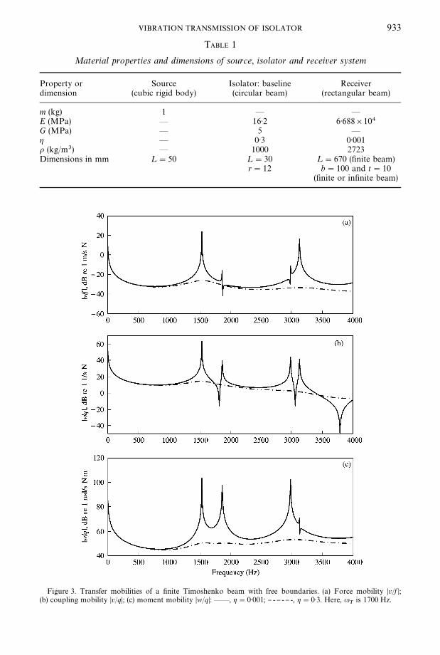
TABLE 1
Material properties and dimensions of source, isolator and receiver system
Property or Source Isolator: baseline Receiverdimension (cubic rigid body) (circular beam) (rectangular beam)
m (kg) 1 * *
E (MPa) * 16)2 6)688]104G (MPa) * 5 *
g * 0)3 0)001o (kg/m3) * 1000 2723Dimensions in mm ¸"50 ¸"30 ¸"670 ("nite beam)
r"12 b"100 and t"10("nite or in"nite beam)
Figure 3. Transfer mobilities of a "nite Timoshenko beam with free boundaries. (a) Force mobility Dv/f D;(b) coupling mobility Dv/qD; (c) moment mobility Dw/qD: **, g"0)001; } - } - } -, g"0)3. Here, u
Tis 1700 Hz.
VIBRATION TRANSMISSION OF ISOLATOR 933

934 S. KIM AND R. SINGH
Also, harmonic responses of an in"nite beam for axial (x) and #exural (y) motions are,respectively, as follows where the subscript R denotes the receiver beam. The secondsubscripts R and ¸ in equation (23) are used for the right-travelling and the left-travellingwaves, respectively, and the third subscript implies the direction x or y. Further, k
RLand
kRB
are the longitudinal and bending wave numbers of the receiver beam respectively.
XMRL
(x, t)"XRL
(x) e+ut"ARLx
e+kRLxe+ut, (23a)
XMRR
(x, t)"XRR
(x) e+ut"ARRx
e~+kRLxe+ut, (23b)
>MRL
(x, t)">RL
(x) e+ut"MARLy
e+*kRBx+#BRLy
e *kRBx+Ne+ut, (23c)
>MRR
(x, t)">RR
(x) e+ut"MARRy
e~+*kRBx+#BRRy
e~*kRBx+Ne+ut. (23d)
The governing equations in frequency domain are described as follows where theubiquitous term e+ut is dropped. Here, I
mis the moment of inertia corresponding to a rigid
body source and h is the rigid body location where the isolator is attached. Also, fyand q
are harmonic force and moment excitation amplitudes, respectively, at frequency u.
XRL
(0)"XRR
(0), >RL
(0)">RR
(0), (24a, b)
XRL
(0)"XP(0), >
RL(0)">
P(0), (24c, d)
d>RL
(0)
dx"
d>RR
(0)
dx,
d>RL
(0)
dx"!
dXP(0)
dy, (24e, f )
ERIRS C
d3>RR
(0)
dx3!
d3>RL
(0)
dx3 D"SPEP
d>P(0)
dy, (24g)
iPSPG
Pt1
1!(kP¸
P)4t
1t2C¸2
P
d3XP(0)
dy3#(k
P¸
P)4(t
1#t
2)dX
P(0)
dy D"S
RER C
dXRR
(0)
dx!
dXRL
(0)
dx D , (24h)
ERIRS C
d2>RL
(0)
dx2!
d2>RR
(0)
dx2 D"EPIPS C
d2XP(0)
dy2#
t1
¸2(k
P¸)4X
P(0)D , (24i)
!
iPSPG
Pt1
1!(kP¸
P)4t
1t2C¸2
P
d3XP(¸
P)
dy3#(k
P¸
P)4(t
1#t
2)dX
P(¸
P)
dy D!mu2XP(¸
P)
!mhu2dX
P(¸
P)
dy"0, (24j)
!mu2>P(¸
P)#S
PEP
d>P(¸
P)
dy"f
y, (24k)
!(ImG
#mh2) u2dX
P(¸
P)
dy!mhu2X
P(¸
P)
#EPIPS C
d2XP(¸
P)
dy2#
t1
¸2(k
P¸)4X
P(¸
P)D"q. (24l)

VIBRATION TRANSMISSION OF ISOLATOR 935
Harmonic responses for each excitation are separately obtained by solving the boundaryconditions (24a}l) in terms of the arbitrary constants A, B, C and D. When the harmonicforce f
yis applied at the mass center of the rigid body, the steady state responses are
obtained by letting q"0 in equation (24l). Similarly, the right-hand side of (24k) is set to0 when q is applied at the mass center of rigid body. Internal axial (F ), shear (< ) forces andmoment (M) at interfacial location between an isolator and an in"nite beam receiver arecalculated as follows using the resulting arbitrary constants:
FR"S
RER C
dXRL
(0)
dx!
dXRR
(0)
dx D , MR"E
RIRS C
d2>RL
(0)
dx2!
d2>RR
(0)
dx2 D , (25a, b)
<R"!E
RIRS C
d3>RL
(0)
dx3!
d3>RR
(0)
dx3 D . (25c)
The time-averaged vibrational power (P) components transmitted to an in"nite beamreceiver are obtained by using the resulting harmonic responses and interfacial forces (F and<) and moment (M). De"ne P
x, P
yand Ph as the lateral (x), axial (y) and rotational (h)
power components, respectively:
Px(u)"
1
2Re[FI (u) vJ H
x(u)]"
1
2Re[vJ
x(u)FI H(u)], (26a)
Py(u)"
1
2Re[<I (u) vJ H
y(u)]"
1
2Re[vJ
y(u)<I H(u)], (26b)
Ph (u)"1
2Re[MI (u) wJ H(u)]"
1
2Re[wJ (u)MI H(u)]. (26c)
Here, vx, v
yand w are the axial (shear direction x for isolator), vertical (axial direction y for
isolator) and rotational (h) velocity amplitudes of the receiver beam respectively. Finally, thetotal vibration power transmitted to a receiver beam is
PTotal
(u)"Px(u)#P
y(u)#Ph (u). (27)
Additionally, de"ne the following measures of vibration isolation performance:
C(u)"P
Total(u)
PIN
(u), N (u)"
PTotal,With
(u)
PTotal,Without
(u), (28a, b)
where PIN
is the harmonic power supplied to a rigid body source. For force ( fy) and
moment (q) excitation cases, we "nd
PIN
(u)"fyju>
P(¸
P), P
IN(u)"q ju
dXP(¸
P)
dy. (29a, b)
The governing equations of the system without an isolator are
XRL
(0)"XRR
(0), >RL
(0)">RR
(0),d>
RL(0)
dx"
d>RR
(0)
dx, (30a}c)
!mu2XR(0)#mhu2
d>R(0)
dx#S
RER C
dXRL
(0)
dx!
dXRR
(0)
dx D"0, (30d)

936 S. KIM AND R. SINGH
!mu2>R(0)#E
RIRS C
d3>RR
(0)
dx3!
d3>RL
(0)
dx3 D"fy, (30e)
!(ImG
#mh2) u2d>
RL(0)
dx!mhu2X
R(0)#E
RIRS C
d2>RL
(0)
dx2!
d2>RR
(0)
dx2 D"q. (30f )
Similar to the system with an isolator, harmonic responses of a receiver beam are obtainedusing equations (23a}d). Further, moment, shear force of an in"nite beam and transmittedpower are obtained using equations (25a}c) and (26, 27).
Material properties of the isolator are listed in Table 1. Young's modulus EP
for a rubbermaterial is found from the relation E
P"3G
P(1#Q¹2), where Q is an empirical constant
and ¹ is the shape factor. For a circular rubber cylinder, Q is 2 and ¹ is equal to 2r/(4¸P),
where r and ¸P
are the radius and length of the isolator beam respectively [4]. Also,a frequency-invariant loss factor g
Pis included in the calculation with the complex-valued
Young)s modulus as EIP"E
P(1#jg
P) to incorporate hysteretic damping within the
isolator. Material properties of the receiver beam are, as well as the dimensions of source,also shown in Table 1. A loss factor g
Rof 0)001 is used to represent a lightly damped
structure and is included in the complex-valued EIR. Given the system properties, the e!ects
of shear deformation and rotary inertia of an isolator on the vibration power transmitted toreceiver are examined. Further, the e!ects of isolator material and geometric properties areinvestigated.
4.2. EXAMINATION OF ALTERNATE ISOLATOR MODELS
Vibration power transmission to receiver is analyzed up to 4 kHz when a harmonicmoment is applied at the source. The following four alternate isolator models are employedto describe the #exural vibration power transmitted to an in"nite beam receiver:Timoshenko beam, Euler beam with shear deformation, Euler beam with rotary inertia andEuler beam models. Total vibration power (P) transmitted to a receiver beam is shown inFigure 4 along with the transmission power e$ciency (C) and the e!ectiveness (N) ofvibration power. First, it is observed that rotary inertia does not signi"cantly a!ect thevibration power transmission below u
T, that is, around 1)7 kHz. Note that the measures of
Figure 4 based on the Euler beam isolator with rotary inertia are similar to those using theEuler beam below u
T. Beyond u
T, the discrepancies between measures based on those
alternate models are pronounced as frequency increases. Further, it is seen that the Eulerbeam model with shear deformation provides a closer representation of the Timoshenkobeam isolator even beyond u
Teven though there exist small disagreements between them.
However, large discrepancies between the Timoshenko beam and Euler beam formulationswithout shear deformation are found. Normalized power components with respect to thetotal actual power transmitted to the receiver beam are shown in Figure 5. As mentionedearlier, since each vibration power component is decoupled from the others in total power,each power component is always positive in this case. Only #exural motions are transmittedthrough the mount in this particular example case and therefore only the lateral (sheardirection of the mount) and rotational power components control the total vibration powertransmission. It is observed in Figure 5 that the lateral power component is larger than therotational component when the isolator is modelled using the Timoshenko beam or Eulerbeam with shear deformation. Also, the total vibration power with the Euler beam isolatormodels with and without rotary inertia is almost equally divided into lateral and rotationalcomponents.

VIBRATION TRANSMISSION OF ISOLATOR 937
4.3. EFFECT OF ISOLATOR PROPERTIES ON VIBRATION POWER TRANSMISSION
In order to understand the e!ect of isolator properties, it is useful to examine the staticsti!nesses (K
S) of an isolator. It should be noted that #exural sti!nesses have to be dealt
with in a matrix form since there exist coupling terms between lateral (shear x) androtational (h) sti!nesses. The static sti!nesses of a Euler beam are well known and writtenhere as follows, where the subscript E represents the Euler beam:
Cf
qD"KSE CX
hD"C!12EI/¸3 !6EI/¸2
6EI/¸2 2EI/¸ D CX
hD . (31)
For the static sti!nesses of a Timoshenko beam, the following governing equations are usedfor the sake of convenience:
!GSi CLX2(y)
Ly2!
LhB(y)
Ly D"w(x), (32a)
GSi CLX(y)
Ly!h
B(y)D#EI
S
L2hB(y)
Ly2"0. (32b)
Here, w(x) is the load intensity function and hBis the slope due only to bending of the beam.
Combining the above equations and including the inertia terms yield equation (1) that hasbeen previously used for the harmonic response. The static sti!nesses of the Timoshenkobeam are obtained by using the singularity function for load intensity and displacementfunctions and applying the blocked end boundary condition at one end. The resulting staticsti!ness matrix is as follows, where the subscript ¹ stands for the Timoshenko beam:
Cf
qD"KS¹ CX
hBD"
!
1
¸3/12EIS#¸/GSi
!
1
¸2/6EIS#2/GSi
1
¸2/6EIS#2/GSi
1
¸/3EIS#4/GSi¸
!
EIS
¸
CX
hBD . (33)
From the above equation, the #exural sti!ness terms can be interpreted in terms ofa lumped system that combines the elastic elements due to bending and shear in series.Further, it is seen that KS¹PKSE when GSiPR in equation (33). Equation (33) isexpanded by using the relationships I
S"Sr2
gand G"E/2(1#l), and the KS¹ is rewritten
as follows where KSx
, KSc
and KSh represent the static shear, coupling and rotational
sti!nesses, respectively:
KS¹"CK
SxK
ScK
ScK
ShD"
GS
¸
4r2gi (1#l)
[i¸2#24(1#l) r2g] C
!6 !3¸
3¸ ¸2[1!12(1#l)r2g/i¸2]D . (34)
On the other hand, the static axial (y) sti!ness is
KSy"
ES
¸
"
2GS(1#v)
¸
. (35)
Note that G (or E) is common to all sti!ness terms. The system con"guration of section 4.1is adopted here. Highly damped material with a loss factor of 0)3 is used for this isolator sothat the overall frequency-dependent characteristics are observed without the in#uence of

Figure 4. E!ect of shear deformation and rotary inertia of an isolator on vibration isolation measures with anin"nite beam receiver given a moment excitation. (a) Total transmitted vibration power P
Total; (b) e$ciency C for
total transmitted vibration power; (c) e!ectiveness NP for total transmitted vibration power: **, Timoshenkobeam isolator; )))))))))), Euler beam isolator with shear deformation; - - - - - -, Euler beam isolator with rotatoryinertia; } - } - } -, Euler beam isolator.
938 S. KIM AND R. SINGH
isolator resonances. Results for C are shown in Figure 6(a) for a variation in G values for anisolator when a harmonic moment is applied to the mass center of a rigid body source. It isobserved in Figure 6(a) that C rises due to an increase in G as the frequency increases. Next,
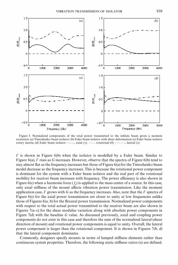
Figure 5. Normalized components of the total power transmitted to the in"nite beam given a momentexcitation. (a) Timoshenko beam isolator; (b) Euler beam isolator with shear deformation; (c) Euler beam isolatorrotary inertia; (d) Euler beam isolator: - - - - -, axial (y); **, rotational (h); } - } - } -, lateral (x).
VIBRATION TRANSMISSION OF ISOLATOR 939
C is shown in Figure 6(b) when the isolator is modelled by a Euler beam. Similar toFigure 6(a), C rises as G increases. However, observe that the spectra of Figure 6(b) tend tostay almost #at as the frequency increases but those of Figure 6(a) for the Timoshenko beammodel decrease as the frequency increases. This is because the rotational power componentis dominant for the system with a Euler beam isolator and the real part of the rotationalmobility for receiver beam increases with frequency. The power e$ciency is also shown inFigure 6(c) when a harmonic force ( f
y) is applied to the mass center of a source. In this case,
only axial sti!ness of the mount a!ects vibration power transmission. Like the momentapplication case, C grows with G as the frequency increases. Also, note that the C spectra ofFigure 6(c) for the axial power transmission are closer to unity at low frequencies unlikethose of Figures 6(a, b) for the #exural power transmission. Normalized power componentswith respect to the total actual power transmitted to the receiver beam are also shown inFigures 7(a}c) for the shear modulus variation along with absolute power components inFigure 7(d) with the baseline G value. As discussed previously, axial and coupling powercomponents do not exist in this case and therefore the sum of the normalized lateral (sheardirection of mount) and rotational power components is equal to unity. Overall, the lateralpower component is larger than the rotational component. It is shown in Figures 7(b, d)that the lateral component dominates.
Commonly, designers specify mounts in terms of lumped sti!ness elements rather thancontinuous system properties. Therefore, the following static sti!ness ratios (a) are de"ned.

Figure 6. E!ect of shear modulus G of an isolator beam on e$ciency (C ) with an in"nite beam receiver. (a) Fora Timoshenko beam isolator model; (b) for an Euler beam isolator model given a moment excitation; (c) givena force excitation f
y: } - } - } -, 0)5G; **, G; - - - - -, 2G.
940 S. KIM AND R. SINGH
Here, each ratio is normalized with respect to the axial component:
axy"
KSx
KSy
, acy"
KSc
KSy
, ahy"K
ShK
Sy
, (36a}c)

Figure 7. Vibration transmitted to the in"nite beam given a moment excitation. (a) Normalized power for 0)5G;(b) normalized power for G; (c) normalized power for 2G; (d) power in W for G: - - - - -, axial (y);**, rotational (h);} - } - } -, lateral (x).
VIBRATION TRANSMISSION OF ISOLATOR 941
where axy
, acy
and ahy are the ratios of shear, coupling and rotational sti!ness components tothe axial sti!ness respectively. For a cylindrical isolator, the static #exural sti!nesses ofequation (34) are represented in terms of the static axial sti!ness (K
Sy) as follows by using
equations (34) and (35):
KS¹"iK2
Sy4(1#l)[nGi¸#3K
Sy] C
!6 !3¸
3¸ ¸2[1!3KSy
/2ni¸G]D . (37)
Key parameters include the slenderness ratio (S/¸), material properties (G and l) and KSy
.In this case, it is observed from equation (37) that the #exural sti!nesses change when ¸ isvaried proportionally to S, unlike the K
Syvalue. Note that this behavior is also true for the
Euler beam case. Note that axy
decreases but both acy
and ahy increase as the ¸ or S valueincreases, while holding S/¸, G and l. The e!ects of a
xyon e$ciency (C) are examined in
Figure 8 for the case when¸ proportionally varies with S. Figure 8(a) shows that C increasesas a
xyincreases at higher frequencies when a harmonic moment is applied at the mass center
of a source. Similar to the previous case, C with an isolator modelled by a Euler beam isshown in Figure 8(b). Unlike the system with a Timoshenko beam isolator, C decreases asaxy
increases at higher frequencies. Note that the minimum value of axy
produces the bestvibration isolation (hence the lowest C ) for a system with a Timoshenko beam isolator asshown in Figure 8(a). Therefore, shear deformation and rotary inertia play important roles

Figure 8. E!ect of axy
(ratio of shear to axial components of static sti!ness) of an isolator beam on e$ciency (C)with an in"nite beam receiver. (a) For a Timoshenko beam isolator model given a moment excitation; (b) fora Euler beam isolator model given a moment excitation; (c) given a force excitation f
y: } - } - } -, 0)7a
xy; **, a
xy;
- - - - -, 1)3axy
.
942 S. KIM AND R. SINGH
in in#uencing isolation measures. The C spectra are shown in Figure 8(c) when a harmonicforce ( f
y) is applied to a source. Note that K
Syis the only component that a!ects the power
transmission and KSy
is unchanged as axy
is varied in this case. As expected, C remains

Figure 9. Vibration transmitted to the in"nite beam given a moment excitation. (a) Normalized power for0)7a
xy; (b) normalized power for a
xy; (c) normalized power for 1)3a
xy; (d) power in W for 0)7a
xy: - - - - -, axial (y);**,
rotational (h); } - } - } -, lateral (x).
VIBRATION TRANSMISSION OF ISOLATOR 943
unchanged for the axy
variations at lower frequencies. However, it is observed in Figure 8(c)that C increases as a
xyincreases at higher frequencies. Similar to the previous case, vibration
power components are calculated in Figure 9. The dominance of lateral and rotationalpower components changes at a certain frequency for the lowest a
xyvalue as shown in
Figures 9(a, d) for both normalized and absolute powers respectively. Observe that for thelowest a
xyvalue case the rotational power component is dominant at lower frequencies and
continues to dominate up to the mid-frequency regime where the lateral component isimportant. However, the lateral component becomes more signi"cant when a
xyis increased
and the rotational component is negligible for the highest axy
case. Next, the e!ects of theisolator shape on isolation measures are examined. The shape factor (b) of an isolator isde"ned as b"¸/d. Note that an increase in b reduces the static #exural and axial sti!nessesas seen from equations (34) and (35). Results are shown in Figure 10. The C value decreasesat higher frequencies as b increases for both the Timoshenko and Euler beam isolatormodels when a moment is applied. Similar to the moment excitation case, C decreases athigher frequencies as b increases for a force ( f
y) excitation case as shown in Figure 10(c).
Normalized and absolute vibration power components are also shown in Figure 11 for thelowest b case. Like the previous cases, the lateral component is larger than the rotationalcomponent over all the frequencies. However, the rotational component becomes moreimportant at lower and higher frequencies as b is increased.

Figure 10. E!ect of isolator shape factor b on e$ciency (C) with an in"nite beam receiver. (a) For a Timoshenkobeam isolator model given a moment excitation; (b) for a Euler beam isolator model given a moment excitation;(c) given a force excitation f
y: } - } - } -, 0)5b; **, b; - - - - -, 2b.
944 S. KIM AND R. SINGH
5. VIBRATION POWER TRANSMITTED TO A FINITE BEAM RECEIVER
A "nite beam receiver (with clamped ends) is employed to examine the vibrationtransmission through the isolator for a system of Figure 1(a). Similar to the system with an

Figure 11. Vibration transmitted to the in"nite beam given a moment excitation. (a) Normalized power for 0)5b;(b) normalized power for b; (c) normalized power for 2b; (d) power in W for 0)5b: - - - - -, axial (y);**, rotational(h); } - } - } -, lateral (x).
VIBRATION TRANSMISSION OF ISOLATOR 945
in"nite beam receiver, the Timoshenko beam model and its subsets represent #exuralmotion of an isolator along with the wave equation for longitudinal motion. Harmonicresponses for axial (x) and #exural (y) motions of the receiver beam are, respectively, asfollows using the notations of section 4.1:
XMRL
(x, t)"XRL
(x) e+ut"[ARLx
e~+kRLx#BRLx
e+kRLx] e+ut, (38a)
XMRR
(x, t)"XRR
(x) ejut"[ARRx
e~+kRLx#BRRx
e+kRLx] e+ut, (38b)
>MRL
(x, t)">RL
(x) e+ut"MARLy
e~+*kRBx+#BRLy
e~*kRBx+#CRLy
e+*kRBx+#DRLy
e*kRBx+Ne+ut,
(38c)
>MRR
(x, t)">RR
(x) e+ut"MARRy
e~+*kRBx+#BRRy
e~*kRBx+#CRRy
e+*kRBx+#DRRy
e*kRBx+Ne+ut.
(38d)
The harmonic responses for the isolator are still given by equations (22a, b). The arbitraryconstants of the harmonic responses are obtained by solving the following governingequations in addition to equations (24a}l), where ¸
Ris the total length of the receiver beam
and ¸RI
is the length between one clamped end and the junction of receiver and isolator:
XRL
(!¸RI
)"0, XRR
(¸R!¸
RI)"0, (39a, b)

946 S. KIM AND R. SINGH
>RL
(!¸RI
)"0, >RR
(¸R!¸
RI)"0, (39c, d)
d>RL
(!¸RI
)
dx"0,
d>RR
(¸R!¸
RI)
dx"0. (39e, f )
Finally, PTotal
, C and N are obtained by using equations (25}28) and the resulting harmonicresponses, like the in"nite beam receiver calculation. An isolator connected to a rigid bodysource at one end is assumed to be located o!-center (¸
RI"3¸
R/4) of the receiver beam in
order to incorporate the e!ect of coupling mobility of the receiver beam. Note that sucha coupling mobility does not exist for both centrally driven beam (with both ends clamped)and an in"nite beam.
Figure 12 shows the PTotal
, C and N for a system with various Timoshenko beam models.Results are given in terms of 1/3 octave band center frequencies from 20 to 4000 Hz andonly the mean values within each bandwidth are plotted in Figure 12 and similarly inFigures 13}15. Similar to the system with an in"nite beam receiver, the Euler beam isolatorwith shear deformation well represents the Timoshenko beam model except for thefrequencies around 2)5 kHz. Further, three isolation measures for the Euler beam isolatorwith rotary inertia are similar to those with the Euler beam isolator at frequencies less thanu
T. But discrepancies between the Euler beam isolator models that include or exclude
rotary inertia are pronounced as the frequency increases. However, it is observed fromFigure 12 that the Euler beam isolator models without shear deformation show largedeviations from those with shear deformation. The aforementioned behavior is analogousto the results observed for the in"nite beam receiver. The e!ects of G of a Timoshenko beamisolator on C are shown in Figure 13(a) when a moment is applied at a source. Like thein"nite beam receiver case, C increases especially at higher frequencies as G of an isolatorincreases. However, the deviation from the aforementioned behavior is observed at certainfrequencies (around 2 kHz) due to the coupling mobility and resonances of the receiverbeam. Figure 13(b) shows the C spectra with the Euler beam isolator for a momentexcitation case. Again, C rises with G, but the increases in C are not as much as thosewith the Timoshenko beam isolator. Like the system with an in"nite beam receiver, Cf the isolator in Figure 13(b) grows as the frequency increases. But C of the Timoshenkobeam isolator shows the relatively #at spectra over the frequencies as shown inFigure 13(a). When a force f
yis applied to a source, C increases as G increases as shown in
Figure 13(c). Unlike the case of an in"nite beam receiver, C is not closer to unity at lowfrequencies.
Next, the e!ect of axy
is examined while holding the slenderness and material properties ofthe mount. Results are shown in Figure 14 for a moment excitation case. Similar to thein"nite beam receiver case, C increases at higher frequencies as a
xyof the Timoshenko beam
isolator increases as shown in Figure 14(a). However, the di!erences in C between thehigher a
xyvalues are not signi"cant for the Euler beam isolator as shown in Figure 14(b).
This observation implies that the axy
in#uences the shear deformation e!ect of an isolator.Despite the small di!erences, Figure 14(b) shows that C decreases at higher frequencies asaxy
increases for the Euler beam isolator case, like the system with an in"nite beam receiver.In addition, C is shown in Figure 14(c) when a force f
yis applied and observe that
C increases at higher frequencies as axy
increases like the moment excitation case eventhough the static axial sti!ness (K
Sx) plays a major role in this force excitation case;
KSx
remains unchanged for all axy
variations. Note that C remains unchanged up toa certain frequency (around 800 Hz in this case) as a
xyis varied, as shown in Figure 14(c).
Finally, the e!ects of b on C are examined in Figure 15. Similar to the in"nite beam receivercase, an increase in b decreases C for both moment and force excitation cases.

Figure 12. E!ect of shear deformation and rotary inertia of an isolator on vibration isolation measures witha "nite beam receiver given a moment excitation. (a) Total transmitted vibration power P
Total; (b) e$ciency C for
total transmitted vibration power; (c) e!ectiveness NP for total transmitted vibration power: **, Timoshenkobeam isolator; ))))))))), Euler beam isolator with shear deformation; - - - - -, Euler beam isolator with rotatory inertia;} - } - } -, Euler beam isolator. Results are given in terms of 1/3 octave band center frequencies from 20 to 4000 Hzand only the mean values within each bandwidth are plotted here and in Figures 13}15.
VIBRATION TRANSMISSION OF ISOLATOR 947

Figure 13. E!ect of isolator G on e$ciency (C) with a "nite beam receiver. (a) For a Timoshenko beam isolatormodel given a moment excitation; (b) for a Euler beam isolator model given a moment excitation; (c) given a forceexcitation f
y: } - } - } -, 0)5G; **, G; - - - - -, 2G.
948 S. KIM AND R. SINGH
6. CONCLUSION
The chief contribution of this paper is the application of continuous system theory to anelastomeric isolator and the examination of associated #exural and longitudinal motions of

Figure 14. E!ect of isolator axy
on e$ciency (C) with a "nite beam receiver. (a) For a Timoshenko beam isolatormodel given a moment excitation; (b) for a Euler beam isolator model given a moment excitation; (c) given a forceexcitation f
y: } - } - } -, 0)3a
xy; **, a
xy; - - - - -, 1)3a
xy.
VIBRATION TRANSMISSION OF ISOLATOR 949
the source}path}receiver system. Two di!erent frequency response characteristics of anelastomeric isolator are predicted by the Timoshenko beam theory. The second typesolution, that has been previously believed to occur at extremely high frequencies (say

Figure 15. E!ect of isolator shape factor b on e$ciency (C) with a "nite beam receiver. (a) For a Timoshenkobeam isolator model given a moment excitation; (b) for a Euler beam isolator model given a moment excitation;(c) given a force excitation f
y: } - } - } -, 0)5b; **, b; - - - - -, 2b.
950 S. KIM AND R. SINGH
around 80 kHz) for metallic structures and therefore not of interest in structural dynamics,takes place at relatively low frequencies (say around 1)5 kHz) for a rubber-like material. Thebehavior of a typical vibration isolation system has been examined using the power
VIBRATION TRANSMISSION OF ISOLATOR 951
transmitted to an in"nite beam or a "nite beam receiver, when excited by a harmonicmoment or force at the source. The continuous system analysis clearly shows that the sheardeformation and rotary inertia must be considered in order to properly describe thetransmission of #exural motions at higher frequencies. In particular, the shear deformatione!ect is found to be more pronounced than the role of the rotary inertia, as evaluated by thepower-based vibration isolation measures at higher frequencies. Parametric study ofisolator parameters on the transmission measures has been conducted using theTimoshenko beam isolator model and an in"nite beam receiver. Material and geometricparameters of an isolator have been examined along with the static sti!ness ratios (betweenK
Sy, K
Sxand K
Sh components). The vibration power e$ciency, e!ectiveness and powertransmitted to an in"nite beam structure increase with frequency as the isolator shearmodulus increases. Resulting characteristics for a system with a "nite beam receiver con"rmthe trends.
Future work is required to quantify the vibration source in terms of power transmission.Future analysis must also incorporate the e!ect of compliant sources for a single ora multi-isolator system on the vibration power transmission. Further, an experimentalinvestigation is needed to con"rm the phenomena identi"ed in this article. Properinterpretation of various vibration isolation measures for a multi-dimensional system, suchas power e$ciency and e!ectiveness, must also be sought over a broad range of frequencies.Finally, non-linear e!ects of an isolator should be examined.
ACKNOWLEDGMENTS
The General Motors Corporation (Noise and Vibration Center) and the Goodyear Tireand Rubber Company (Transportation Molded Products) are gratefully acknowledged forsupporting this research.
REFERENCES
1. T. JEONG and R. SINGH 2001 Journal of Sound and <ibration 245, 385}415. Inclusion of measuredfrequency- and amplitude-dependent mount properties in vehicle or machinery models.
2. H. G. D. GOYDER and R. G. WHITE 1980 Journal of Sound and <ibration 68, 97}117. Vibrationalpower #ow from machines into built-up structures, part III: power #ow through isolation systems.
3. J. I. SOLIMAN and M. G. HALLAM 1968 Journal of Sound and <ibration 8, 329}351. Vibrationisolation between non-rigid machines and non-rigid foundations.
4. J. C. SNOWDON 1968 <ibration and Shock in Damped Mechanical Systems. New York: John Wiley& Sons, Inc.
5. M. A. SANDERSON 1996 Journal of Sound and <ibration 198, 171}191. Vibration isolation:moments and rotations included.
6. W. L. LI and P. LAVRICH 1999 Journal of Sound and <ibration 224, 757}774. Prediction of power#ows through machine vibration isolators.
7. J. PAN, J. PAN and C. H. HANSEN 1992 Journal of the Acoustical Society of America 92, 895}907.Total power #ow from a vibrating rigid body to a thin panel through multiple elastic mounts.
8. E. E. UNGAR and C. W. DIETRICH 1966 Journal of Sound and <ibration 4, 224}241.High-frequency vibration isolation.
9. L. L. BERANEK 1988 Noise and <ibration Control. Washington, DC: Institute of Noise ControlEngineering.
10. P. GARDONIO, S. J. ELLIOTT and R. J. PINNINGTON 1997 Journal of Sound and <ibration 207,61}93. Active isolation of structural vibration on a multiple-degree-of-freedom system, part I: thedynamics of the system.
11. P. GARDONIO and S. J. ELLIOTT 2000 Journal of Sound and <ibration 237, 483}511. Passive andactive isolation of structural vibration transmission between two plates connected by a set ofmounts.

952 S. KIM AND R. SINGH
12. S. KIM and R. SINGH 2001 Journal of Sound and <ibration 245, 877}913. Multi-dimensionalcharacterization of vibration isolators over a wide range of frequencies.
13. L. F. NIELSEN, N. J. WISMER and S. GADE 2000 Sound and<ibration 20}24. An improved methodfor estimating the dynamic properties of materials.
14. L. CREMER, M. HECKLE and E. E. UNGAR 1973 Structure-Borne Sound: Structural<ibrations andSound Radiation at Audio Frequencies. New York: Springer-Verlag.
15. R. G. DEJONG, G. E. ERMER, C. S. PAYDENKAR and T. M. REMTEMA 1998 Noise-Con 98,>psilanti, Michigan, ;.S.A. High frequency dynamic properties of rubber isolation elements.
16. R. W. TRAILL-NASH and A. R. COLLAR 1953 Quarterly Journal of Mechanics and AppliedMathematics 6, 186}222. The e!ect of shear #exibility and rotary inertia on the bending vibrationsof beams.
17. J. F. DOYLE 1997=ave Propagation in Structures: Spectral Analysis ;sing Fast Discrete Fourier¹ransforms. New York: Springer-Verlag.
18. S. GOPALAKRISHNAN, M. MARTIN and J. F. DOYLE 1992 Journal of Sound and <ibration 158,11}24. A matrix methodology for spectral analysis of wave propagation in multiple connectedTimoshenko beams.
19. R. E. D. BISHOP and D. C. JOHNSON 1960 ¹he Mechanics of <ibration. Cambridge: CambridgeUniversity Press.
APPENDIX A: NOMENCLATURE
A, B, C, D arbitrary constantsb widthd diameterE Young's modulusf force amplitudeF axial forceG shear modulush distance between rigid body center and mount interfaceIS
area moment of inertiaIm
mass moment of inertiaj J!1k wave numberK sti!nessK sti!ness matrix¸ lengthm massM momentq moment amplitudeQ empirical constant for rubber materialr radiusrg
radius of gyrationR variable for root transitionS areat thickness¹ shape factor for rubber materialv translational velocity< shear forcew load intensity functionw rotational velocityX displacement in x direction> displacement in y directionx, y, z Cartesian co-ordinatesa static sti!ness ratiob shape factor of isolator (¸/d)C e$ciency of vibration powerg loss factorh rotational displacement
VIBRATION TRANSMISSION OF ISOLATOR 953
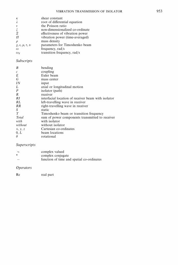
i shear constantj root of di!erential equationl the Poisson ratiom non-dimensionalized co-ordinateN e!ectiveness of vibration powerP vibration power (time-averaged)o mass densitys, e, k, q, t parameters for Timoshenko beamu frequency, rad/su
Ttransition frequency, rad/s
Subscripts
B bendingc couplingE Euler beamG mass centerIN input¸ axial or longitudinal motionP isolator (path)R receiverRI interfacial location of receiver beam with isolatorR¸ left-travelling wave in receiverRR right-travelling wave in receiverS static¹ Timoshenko beam or transition frequency¹otal sum of power components transmitted to receiverwith with isolatorwithout without isolatorx, y, z Cartesian co-ordinates0, ¸ beam locationsh rotational
Superscripts
& complex valued* complex conjugate! function of time and spatial co-ordinates
Operators
Re real part