Jøtul F 3 CB - Tall Pines Farm Stoves & Fireplacess Manual/Manual... · Jøtul F 3 CB woodstove,...
24
Jøtul F 3 CB Installation and Operating Instructions for the USA and Canada 2 Exploded view 20 Kindly save these instructions for future reference. Jøtul F 3 CB Manual Version R14
Transcript of Jøtul F 3 CB - Tall Pines Farm Stoves & Fireplacess Manual/Manual... · Jøtul F 3 CB woodstove,...
Jøtul F 3 CB
Installation and Operating Instructions for the USA and Canada
2Exploded view
20
Kindly save these instructions for future reference.
Jøtul F 3 CBM
anual Version R14
2
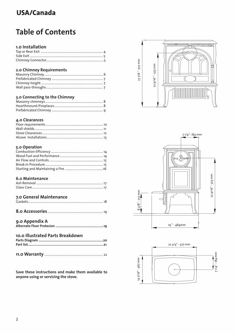
Table of Contents
1.0 InstallationTop or Rear Exit ............................................................................ 4Side Exit .......................................................................................... 5Chimney Connector.......................................................................5
2.0 Chimney RequirementsMasonry Chimney ........................................................................ 6Prefabricated Chimney ............................................................... 7Chimney height ............................................................................ 7Wall pass-throughs ...................................................................... 7
3.0 Connecting to the ChimneyMasonry chimneys ....................................................................... 8Hearthmount/Fireplaces ............................................................ 8Prefabricated Chimney ............................................................... 9
4.0 ClearancesFloor requirements ...................................................................... 10Wall shields .................................................................................... 11Stove Clearances ........................................................................... 12Alcove Installations ..................................................................... 13
5.0 OperationCombustion Efficiency ................................................................ 14Wood Fuel and Performance ..................................................... 14Air Flow and Controls .................................................................. 15Break-in Procedure ....................................................................... 15 Starting and Maintaining a Fire ...............................................16
6.0 MaintenanceAsh Removal .................................................................................. 17Glass Care ....................................................................................... 17
7.0 General MaintenanceGaskets ............................................................................................ 18
8.0 Accessories .................................................................... 19
9.0 Appendix AAlternate Floor Protecion ....................................................19
10.0 Illustrated Parts BreakdownParts Diagram ......................................................................20Part list..................................................................................21
11.0 Warranty ........................................................................ 22
Save these instructions and make them available to anyone using or servicing the stove.
22 9
/16
" - 5
73 m
m
27 7
/8 "
-707
mm
7 1/4"- 184 mm
19 " - 484mm
8 3/
8" -
212
mm
22 9
/16"
- 57
3 m
m
22 3/4" - 577 mm
7 1/
4" -
184
mm
14 7
/16"
- 36
7 m
m
USA/Canada

3
Check Building CodesWhen installing, operating and maintaining your Jøtul F 3 CB woodstove, follow the guidelines presented in these instructions, and make them available to anyone using or servicing the stove.Your city, town, county or province may require a building permit to install a solid fuel burning appliance. In the U.S., the National Fire Protection Association’s Code, NFPA 211, Standards for Chimneys, Fireplaces, Vents and Solid Fuel Burning Appliances, or similar regulations, may apply to the installation of a solid fuel burning appliance in your area. In Canada, the guideline is established by the CSA Standard, CAN/CSA-B365-M93, Installation Code for Solid-Fuel-Burning Appliances and Equipment.
Always consult your local building inspector or authority having jurisdiction to determine what regulations apply in your area.
USA/Canada
StandardsThe Jøtul F 3 CB solid fuel heater has been tested and listed to : U.S. Standards: ANSI/UL 737 and ANSI/UL 1482. Canadian Standards: CAN/ULC-S627-M00 and CAN/ULC-S628-M93
Certified Safety Tests performed by: Intertek Testing Services, Middleton, Wisconsin U.S.A.
Manufactured by: Jøtul AS P.O. Box 1411, Fredrikstad, Norway andJøtul North America, Inc.55 Hutcherson DriveGorham, Maine 04038, USA
Combustion Specifications
Heat Output*: Under specific test conditions, this heater has been shown to deliver heat ranging from 11,400 to 43,500 BTU’s.
Efficiency*: 63%
CO Emissions: N/A
Pariculate Emissions: 3.8 g/h
* Default values per previous Federal Register 40 CFR Part 60, Subpart AAA.
EPA validated efficiency and CO values were unavailable at the time of this printing. These values will be made available in the manual and on the Jotul website (www.jotul.us) for your reference in the near future.
Installation and Operation Instructions for North AmericaSafety Notice: If this solid fuel room heater is not properly installed, a house fire may result. For your safety, follow the installation directions. Contact local building or fire officials about restrictions and installation inspection requirements in your area.
This manual describes the installation and operation of the Jøtul F 3 CB non-catalytic wood heater. Read this entire manual before you install and use your new stove. Save these instructions for future reference.
This wood heater needs periodic inspection and repair for proper operation. See this manual for specific information. It is against federal regulations to operate this wood heater in a manner inconsistent with the operating instructions in this owner’s manual.
This heater meets the 2015 U.S. Environmental Protection Agency’s
emission limits for wood heaters manufactured after May 15, 2015.
This heater may not to be sold after May 15, 2020.
WARNING !THIS WOOD HEATER HAS A MANUFACTURER-SET MINIMUM LOW BURN RATE THAT MUST NOT BE ALTERED. IT IS AGAINST FEDERAL REGULATIONS TO ALTER THIS SETTING OR OTHERWISE OPERATE THIS WOOD HEATER IN A MANNER INCONSISTENT WITH OPERATING INSTRUCTIONS IN THIS MANUAL.
See Sect. 5.0 of this manual for important information regarding the safe, proper, and most efficient operation of your stove.

4
1.0 Installation
NOTE: Your local officials have final authority in determining if a proposed installation is acceptable. Any requirement that is not specifically addressed in this manual defaults to NFPA 211, and local codes in the U.S. or in Canada, CAN/CSA-B365-M and local codes.
Installing the VentingThe Jøtul F 3 can be vented from the top, the rear or from either the right or left side. Follow the instructions below for the desired venting location.
Top-exit VentingWhen top exit venting is desired, use a 3mm allen wrench to remove the two set screws that secure the top casting to the sides of the stove and lift off the top casting. Lay the top casting upside-down on a flat surface. Remove the 10mm bolt from the cross bar and remove the smoke outlet cover. See figure 1.NOTE: Ivory and Majolica stoves are built for rear-exit flue connection - the rear outlet is left open. THE SMOKE OUTLET COVER PLATE MUST BE REINSTALLED OVER THE REAR OPENING BEFORE REPLACING THE TOP PLATE.S e c u re t h e t o p p l a t e t o t h e s t o ve b o d y b y tightening the set screws previously loosened.
Rear-exit VentingWhen rear exit venting is desired it will be necessary to “knock-out” the vent hole from the rear casting on Matte Black and Blue Black stoves. Ivory and Brown Majolica enamel stoves are built with the rear outlet open. Remove the top casting of the stove by removing the two 3mm set screws that secure the top to the sides. The set screws are located on the outside of the stove on the top of each side panel. Use a 10mm wrench to remove the double rear heatshields from the back of the stove. Remove the front door to avoid damage to the glass. NOTE: Loss of the hinge washer will result in improper door alignment when reinstalling the door.
USA/Canada
Stove pipe stop
Traverse bar securing smoke outlet cover to top casting
Stove pipe top
Fig. 1Upside downTop casting
Safety Notices• BURN SOLID, NATURAL WOOD FUEL ONLY. DO NOT
BURN ANY OTHER FUEL.• DO NOT USE CHEMICALS OR FLUIDS TO START A FIRE.
DO NOT BURN GARBAGE OR FLAMABLE FUELS.• DO NOT USE A GRATE OR ELEVATE THE FIRE. BUILD
THE FIRE DIRECTLY ON THE HEARTH.• IF THIS ROOM HEATER IS NOT PROPERLY INSTALLED,
A HOUSE FIRE MAY RESULT. TO REDUCE THE RISK OF FIRE, FOLLOW THE INSTRUCTIONS IN THIS MANUAL. FAILURE TO FOLLOW THESE INSTRUCTIONS MAY RE-SULT IN PROPERTY DAMAGE, BODILY INJURY, OR LOSS OF LIFE.
• CONTACT LOCAL BUILDING OR FIRE OFFICIALS ABOUT RESTRICTIONS AND INSTALLATION INSPECTION RE-QUIREMENTS IN YOUR AREA.
• ANY EXISTING CHIMNEY SYSTEM MUST BE INSPECTED BEFORE INSTALLATION OF THIS APPLIANCE.
• DO NOT CONNECT THIS STOVE TO ANY AIR DISTRIBU-TION DUCT OR SYSTEM.
• EXTREMELY HOT WHILE IN OPERATION! KEEP CHIL-DREN, CLOTHING, AND FURNITURE AWAY. CONTACT WILL CAUSE SKIN BURNS. USE A CHILD GUARD SCREEN TO PREVENT ACCIDENTAL CONTACT BY SMALL CHILDREN.
• INSTALL SMOKE DETECTORS IN THE LIVING AREA AND BEDROOMS OF YOUR HOME. TEST THEM REGULARLY AND INSTALL FRESH BATTERIES TWICE ANNUALLY.
WHEN INSTALLED IN THE SAME ROOM AS THE STOVE, A SMOKE OR CARBON MONOXIDE DETECTOR SHOULD BE LOCATED AS FAR FROM THE STOVE AS POSSIBLE TO PREVENT THE ALARM SOUNDING WHEN ADDING FUEL.
• Avoid creating a low pressure condition in the room where the stove is operating. Be aware that opera-tion of an exhaust fan or clothes dryer can create a low pressure area and consequently promote flow reversal through the stove and chimney system. In some cases, the optional Outside Air Kit #154335 can be used to alleviate this condition. The chimney and building, however, always work together as a system - provision of outside air, directly or indirectly to an atmospherically vented appliance will not guarantee proper chimney performance. Consult your local Jøtul authorized dealer regarding specific installation/per-formance issues.
• Jøtul strongly recommends that this stove be in-stalled by a professional solid fuel technician, or that you consult one if you do the work yourself. Also, consult your insurance company regarding any other specific requirements.

5
Use a hammer to strike the center of the 6” “knock-out” disc from the outside of the stove. The “knock-out” disc will break into four wedges and may need to be tapped out. Touch up any remaining sharp edges with a file or hand grinder.
Reinstall the top casting and front door with hinge washer. Replace the rear heatshields and shield spacer nuts. Remove the metal cover plates from the heatshields and reinstall. Reminder: Reinstall the small nuts used as spacers between the two heatshields. See fig 2.
Side-exit VentingIf venting through the side is desired it will be necessary to remove the top casting. Using a 3mm allen wrench remove the two set screws that secure to the top to the side panels. Remove the front door to avoid damage to the glass. Reminder: Loss of the door washer will result in improper door alignment when reinstalling the door.
Using a claw hammer or a small sledge hammer strike the center of the 6” “knock-out” disc from the inside of the stove. The “knock-out” disc will break into four wedges and may need to be tapped out. Touch up any remaining sharp edges with a file or hand grinder. Reinstall the front door, remembering the washer and the top casting.
Installing the flue collar Place the self-adhesive gasket (Fig.3A) on the underside of the smoke outlet (Fig. 3B).Mount the smoke outlet with use of the supplied screws and cross bar (Fig. 3C)
Secure the first section of stove pipe to the flue collar using two sheet metal screws.
USA/Canada
Fig. 2 Spacer Nuts
Heatshield with listing label should be installed on the outside
Fig.3
Stove pipe - chimney connectorThe chimney connector is a single walled pipe used to connect the stove to the chimney. For use with the Jøtul F3 the chimney connector must be 6” in diameter, with a minimum thickness of 24 gauge black steel.
Aluminum and galvanized steel pipe is not acceptable for use with the Jøtul F3. These materials cannot withstand the extreme temperatures of a wood fire and can give off toxic fumes when heated.
Each chimney connector or stove pipe section must be installed to the stove flue collar and to each other with the male (crimped) end toward the stove. See figure 4.
Fig. 4
Crimped end installedtoward the stove
This prevents any amount of condensed or liquid creosote from running down the outside of the pipe or the stove top. All joints must be secured with three sheet metal screws to ensure that the sections do not separate.
For the best performance the chimney connector should be as short and direct as possible, with no more than two 90° elbows. The maximum horizontal run is 36” and a recommended total length of stove pipe should not exceed 10 feet. Always slope horizontal runs upward 1/4” per foot toward the chimney.
No part of the chimney connector may pass through an attic or roof space, closet or other concealed space, or through a floor or ceiling. All sections of the chimney connectors must be accessible for cleaning.
6
Where passage through a wall or partition of combustible construction is desired, the installation must conform with NFPA 211 or CAN/CSA-B365, and is also addressed in this manual.
Do not connect this unit to a chimney flue servicing another appliance.
Do not use the connector pipe as a chimney.
2.0 Chimney requirementsThere are two types of chimneys suitable for the Jøtul F3:
1. A code- approved masonry chimney with a flue liner.2. A prefabricated chimney complying with the
requirements for type HT (2100°F) chimneys per UL 103 or ULC S629.
The chimney size should not be less than the cross-sectional area of the flue collar, and not more than three times greater than the cross-sectional area of the flue collar.
When selecting a chimney type and the location for the ce of the chimney, as well as the proximity of surrounding trees or buildings.
As a result, a short masonry chimney on the exterior of a house will give the poorest performance. This is because it can be very difficult to warm the chimney thereby creating inadequate draft. In extremely cold northern areas it may be necessary to reline the chimney or extend its height to help establish draft.Oppositely, a tall masonry chimney inside the house is easier to keep warm and will perform the best.
The following guidelines give the necessary chimney requirements based on the national code (ANSI-NFPA 211 for the us. And CSA CAN-B365 for Canada). However, many local codes differ from the national code to take into account climate, altitude, or other factors. It is important that you check with your local building officials to find out what codes apply in your area before installing your new Jøtul F3.
CHIMNEY INSPECTION: A Level II (camera) inspection of an existing chimney system must be conducted by a qualified technician as specified by NFPA 211 when verification of the suitability of the chimney for new or changed conditions of service is needed or when a Level I inspection is not sufficient to determine serviceability of the chimney.
Masonry chimneysWhen installing the Jøtul F3 into a masonry chimney you must conform to all of the following guidelines:• The chimney flue size should not be less than the cross
sectional area of the stove flue collar. • The cross-sectional area of the flue of a chimney with
no walls exposed to the outside below the roofline shall not be more than three times the crosssectional area of the stove flue collar.
• The cross-sectional area of the flue of a chimney with one or more walls exposed to the outside below the roofline shall not be more than two times the cross-sectional area of the stove flue collar.
• Larger chimney flues should be relined with a listed or code approved liner.
• The masonry chimney must have a fireclay liner or equivalent, with a minimum thickness of 5/8” and must be installed with refractory mortar. There must be at least 1/2” air space between the flue liner and chimney wall.
• The fireclay flue liner must have a nominal size of 8” x 8”, and should not be larger than 8”x 12”. If a round fireclay liner is to be used it must have a minimum inside diameter of 6” and not larger than 8” in diameter. If a chimney with larger dimensions is to be used, it should be relined with an appropriate liner that is code approved.
• The masonry wall of the chimney, if brick or modular block, must be a minimum of 4” nominal thickness. A mountain or rubble stone wall must be at least 12” thick.
• A newly-built chimney must conform to local codes and in their absence must recognize national regulations.
• When using an existing chimney, it must be inspected by a professional licensed chimney sweep, fire official, or code officer, to ensure that the chimney is in proper working order.
• No other appliance can be vented into the same flue.• An airtight clean-out door should be located at the
base of the chimney.
Prefabricated chimneysIf a prefabricated metal chimney is to be used it must be a chimney type that is tested and listed for use with solid fuel burning appliances. High temperature (ht) chimney standard UL103 for the U.S. And high temperature standard ULC S-629 for Canada.
The manufacturer’s installation instructions must be followed precisely. Always maintain the proper clearance to combustibles as established by the pipe manufacturer. This clearance is usually a minimum of 2”, although it may vary by manufacturer or for certain chimney components.
USA/Canada
7
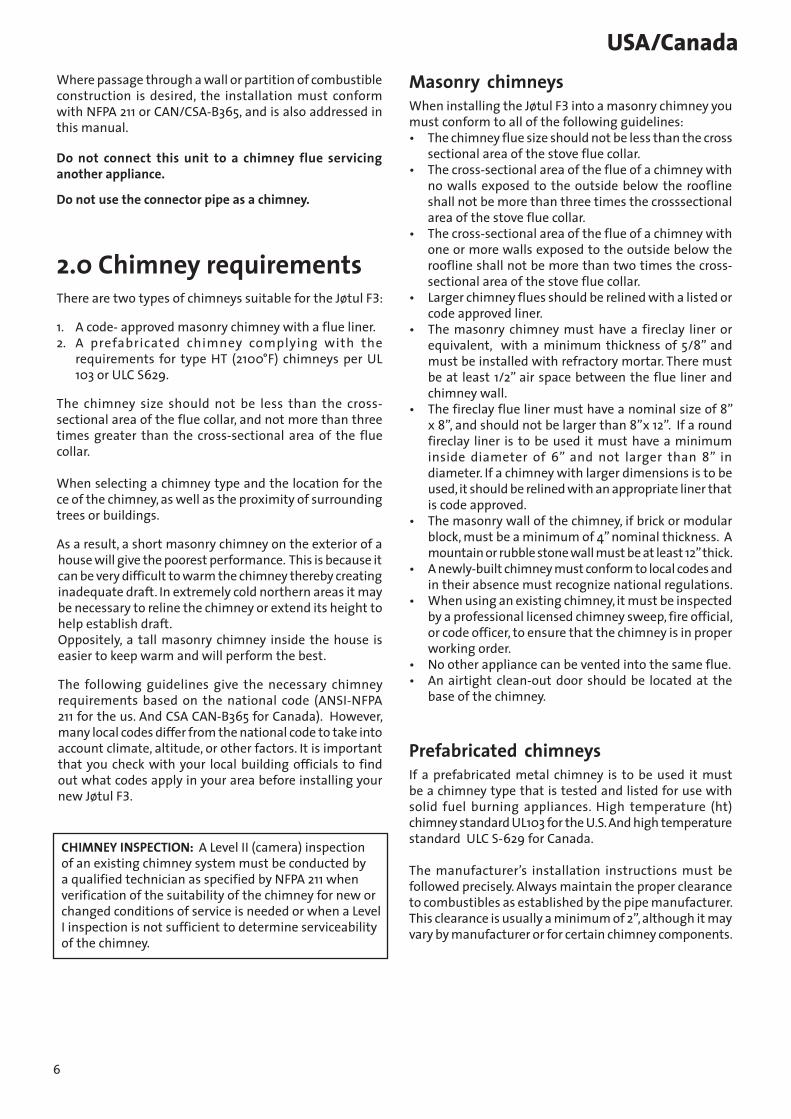
Chimney HeightThe minimum chimney height for the F 3 CB is 15 feet. Whether a masonry chimney or prefabricated metal chimney is used it must rise at least 3 feet higher than the highest point where it passes through the roof and at least 2 feet higher than the highest part of the roof or structure that is within 10 feet of the chimney, measured horizontally. See figure 6.
Fig. 6
At least 3 feet
At least 3 feet
10 feet
Chimneys shorter than 15 feet may not provide adequate draft. This could result is smoke spilling into the room from the stove when loading the stove, or when the door is open. In addition, inadequate draft can cause back puffing, which is a build up of gases inside the firebox.
Other times, chimney height can create excessive draft which can cause high stove temperatures and short burn times. Excessive drafts can be corrected by installing a butterfly damper. If you suspect you have a draft problem, consult your dealer.
Wall pass-throughsWhen your installation unavoidably requires the chimney connector to pass through a combustible wall to reach the chimney, always consult your local building officials, and be sure any materials to be used have been tested and listed for wall pass-throughs.
In the U.S.The national fire protection association’s publication, NFPA 211, standard for chimneys, fireplaces, vents and solid fuel burning appliances permits four methods for passing through a combustible wall. Before proceeding with any method be sure to consult with your local building officials to discuss any local code requirements.
Common method When passing through a combustible wall to a masonry chimney this method requires the removal of all
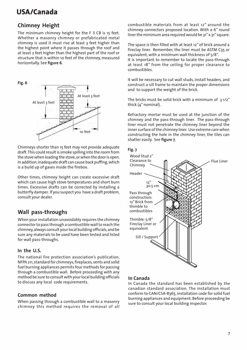
USA/Canadacombustible materials from at least 12” around the chimney connectors proposed location. With a 6” round liner the minimum area required would be 31” x 31” square.
The space is then filled with at least 12” of brick around a fireclay liner. Remember, the liner must be ASTM C35 or equivalent, with a minimum wall thickness of 5/8”. It is important to remember to locate the pass-through at least 18” from the ceiling for proper clearance to combustibles.
It will be necessary to cut wall studs, install headers, and construct a sill frame to maintain the proper dimensions and to support the weight of the brick.
The bricks must be solid brick with a minimum of 3 1/2” thick (4” nominal).
Refractory mortar must be used at the junction of the chimney and the pass-through liner. The pass-through liner must not penetrate the chimney liner beyond the inner surface of the chimney liner. Use extreme care when constructing the hole in the chimney liner, the tiles can shatter easily. See figure 7.
Fig. 7Wood Stud 2”Clearance toChimney
Header
12”30.5 cm
Pass throughconstruction:12” Brick fromthimble tocombustibles
Sill / Support
Flue Liner
Thimble: 5/8”Fireclay Liner orequivalent
In Canada In Canada the standard has been established by the canadian standard association. The installation must conform to CAN/CSA-B365, installation code for solid fuel burning appliances and equipment. Before proceeding be sure to consult your local building inspector.

8
Fig. 8
Connector pipe mustbe flush with the inside of the flue tile
ChimneyConnectorPipe
Thimble
Flue Tile
Make sure the connector pipe or thimble sleeve does not protrude into the flue liner, thereby restricting the area the smoke has to flow through. This bottle-neck will have a negative affect on the chimney system.
The chimney connector should be sealed at the thimble with refractory cement and the stove pipe leading to the stove should have a minimum of three screws.
Do not connect this stove to a chimney flue servicing another appliance of any kind.
Hearth-mount into a masonry fireplaceThe Jøtul F 3 may be installed into a masonry fireplace provided the opening is a minimum of 28 1/2” high. The short leg package reduces the stove’s height by 2 1/4”.
When installing the Jøtul F 3 into a masonry fireplace, code requires that the fireplace damper plate be removed or securely fixed in the open position. A connector pipe must then extend from the stove’s flue exit through the damper area of the fireplace and into the chimney tile liner. See figure 9.
Common methodThis method requires the removal of all combustible materials from at least 18” (457mm) around the chimney connector’s proposed location. With a 6” round liner the minimum area required would be 43” x 43” square.
It is important to remember to locate the pass-through at least 25” from the ceiling to maintain the proper clearance to combustibles.
The space that is cleared of combustible materials must then remain empty. Sheet metal panels can then be used to cover the area. However, when using a panel on both sides of the wall each cover must be installed on noncombustible spacers at least 1” from the wall. If one panel of sheet metal is to be used it may be installed flush to the wall.
See section 5.3.1 and 5.3.2 of CAN/CSA - B365-m91.Consult your local building inspector, authorized Jøtul Dealer, NFPA 211 in the U.S. or CAN/CSA-B635 in Canada for other approved wall pass-through methods.
3.0 Connecting to the chimneyMasonry chimneyWhen installing a Jøtul F 3 into a masonry chimney through a “thimble”(the opening through the chimney wall to the flue), the thimble must be lined with ceramic tile or metal and be securely cemented in place.
The chimney connector/stove pipe must slide completely inside the thimble to the inner surface or the flue liner. It may be necessary to make use of a thimble sleeve (a pipe with a slightly smaller diameter than standard stove pipe). This special pipe can be easily installed into a thimble. See Figure 8.
USA/Canada

9
Fig. 9
Tile liner
Connector extends tofirst flue tile
Damper opening is sealedwith sheetmetal plate andsealant
The inside area of the flue liner must not be less than the area of the stove’s flue exit, and cannot be more than three times greater than the cross sectional area of the stove’s flue exit.If the chimney liner is too large to accommodate the stove, an approved relining system must be installed to resize the flue. A new sheet metal damper block-off plate must be installed around the connector pipe at the damper frame and sealed with the proper sealant (usually high-temp silicone).
Fireplace installation must also observe the proper clearances to surrounding trim and mantels (addressed in clearance section of this manual). In addition, fireplace installations must also adhere to the floor protection guidelines specified in the following section.
Prefabricated chimneysWhen installing the Jøtul F 3 to a prefabricated metal chimney always follow the pipe manufacture’s instructions and be sure to use the components that are required. This usually includes some type of “smoke pipe adapter” that is secured to the bottom section of the metal chimney and allows the chimney pipe to be secured to it with three sheet metal screws. See figures 10 and 11.
Fig. 10
Listed CapStorm Collar
Flashing
Combustible Ceiling Joists
Chimney Connector
to Stove
CeilingSupport
FloorProtector
SpecifiedClearance
ListedChimney
AtticInsulationShield
Fig. 11
USA/Canada

10
4.0 Clearances to combustiblesFloor ProtectionFloor protection under the Jøtul F 3, must be one of the following:1. Any non combustible material with an insulative
R value of 1.1.
2. Any UL, ULC or WH hearth board. The bottom heatshield (standard equipment) is required in all installations.
Individual sections of floor protection must be mortared together t,o prevent sparks from falling through to combustible materials. Any carpeting must be removed from under the floor protection.
In the U.S.and CanadaThe Jøtul F 3 must be installed on a non-combustible surface extending a minimum of 16” for U.S. (46 cm for Canada) in front of the stove and 8” (20 cm) on the remaining sides of the stove (measured from side and back panels).
This will result in a minimum floor protection of 39 cm D x 39 cm W. for U.S.,and 104 cm D x 99 cm W for Canada.See figure 12.
In a rear vent installation the floor protection must also extend under the stove pipe a minimum of 2” (5 cm) beyond either side of the pipe.
Fig. 122”(5 cm)
39” U.S(104 cm Can)
39” U.S.(99 cm Can)
Hearth ProtectionA: 8” (20 cm)B: 16” for U.S. (46 cm for Canada)
B
A A
A
USA/Canada
Clearances to walls and ceilingsThe following clearances have been tested to UL and ULC standards and are the minimum clearances specifically established for the Jøtul F 3. (See next page)
The following charts and diagrams give the required clearances you must maintain when installing the Jøtul F 3 near combustible surfaces.
A combustible surface is anything that can burn (i.e. Sheet rock, wall paper, wood, fabrics etc.). These surfaces are not limited to those that are visible and also include materials that are behind non-combustible materials.
If you are not sure of the combustible nature of a material, consult your local fire officials.
Remember: “Fire resistant” materials are considered combustible; they are difficult to ignite, but will burn. Also “fire-rated” sheet rock is also considered combustible.Contact your local building officials about restrictions and installation requirements in your area.
Using shields to reduce clearancesPipe shields: When using listed pipe shields to reduce the connector clearance to combustibles, it must start 1” above the lowest exposed point of the connect pipe and extend vertically a minimum of 25” above the top surface of the stove.Double wall pipe: Listed double wall pipe is an acceptable alternative to connector pipe heatshields.
Wall-mounted protection: When reducing clearances through the use of wall mounted protection:
In the U.S. Refer to NFPA 211, standard for chimneys, fireplaces, vents and solid fuel burning appliances, for acceptable materials, proper sizing and construction guidelines.
In Canada, refer to CAN/CSA-B365, installation code for solid-fuel burning appliances and equipment, also for acceptable materials, proper sizing and construction guidelines.
Stove mounted rear heatshield is standard equipment on all Jøtul F 3`s. No other stove mounted heat shield may be used.

11
USA/Canada
Wall Shield for close clearance
Combustible wallWall Shield
Must be 30” wide and centred behind the stove.Must be 1” off the wall and 1” off the floor.With standard legs, the shield must be 32” high.With optional short legs, the shield must be 30” high.
Combustible wallWall Shield
The wall shield must extenda min. of 4” (102 mm) pastthe side of the stove.
The wall shield must extenda min. of 4” (102 mm) pastthe ash lip of the stove.
Must be 1” off the wall and 1” off the floor.With standard legs, the shield must be 40” high.With optional short legs, the shield must be 38” high.Both shields must extend and join in the corner.
Combustible wallWall shield
The wall shield mustextend a min. of 12” (305mm) past the side of the stove.
The wall shield must extenda min. of 12” (305 mm) pastthe ash lip of the stove.
Must be 1” off the wall and 1” off the floor.With standard legs, the shield must be 40” high.With optional short legs, the shield must be 38” high.Both shields must extend and join in the corner.

12
A
BC
D
Jøtul F 3 Clearances
Stove Clearances Unprotected Surfaces Protected Surfaces Top vent/vertical per NFPA 211 or CAN/CSA-B365-M Side Rear Corner Side Rear Corner Rear heatshield with 24” 25” 18” 10” 14” 10” Single wall pipe 610mm 635mm 460mm 255mm 355mm 255mm Rear heatshield with 18” 10” 14” 6” 6” 6” Double wall pipe or shields 460mm 255mm 355mm 150mm 150mm 150mm
Stove Clearances Unprotected Surfaces Protected Surfaces Rear Vent/Horizontal per NFPA 211 or CAN/CSA-B365-M Side Rear Corner Side Rear CornerRear heatshield with 24” 25” 20” 10” 25” 18”Single wall pipe 610mm 635mm 510mm 255mm 635mm 460mm
Rear heatshield with 18” 14” 17” 6” 6” 6”Double wall pipe or shields 460mm 355mm 430mm 150mm 150mm 150mm
Connector Unprotected Surface Protected Surface Clearances per NFPA 211 or CAN/CSA-B365-M
Singlewall pipe -vertical installations 18” (460mm) 6” (150mm) Double wall pipe-vertical installations pipe mfgr. listing pipe mfgr. listingSingle wall pipe -horizontal installations 18” (460mm) 9” (230mm)Double wall pipe-horizontal installations pipe mfgr. listing pipe mfgr. listing
Dimensions in Inches represent U.S. requirements. Dimensions in Millimeters represent Canadian requirements.
Wall protection is discussed in further detail on page 10 of this manual.
A: Top to Mantel 34” 860 mmB: Top to Top Trim 20” 510 mmC: Side to Side trim 13” 330 mmD: Side to Side Wall 24” 610 mm
USA/Canada
Maximum Mantel Depth: 11 1/2” 292 mmMaximum Top and Side Trim Depth: 1 1/2” 38 mm

13
USA/Canada
NoticeAccessories for woodstoves for clearance reduction have been developed by many manufacturers. If not following the methods of the installation codes, be sure that any accessory you choose has been tested by an independent laboratory and carries the laboratory’s testing mark. Make sure to follow all of the manufacturer’s instructions.
Always contact your local building inspector or fire officials about restriction and requirements in your area. Reminder, it is the local officials who have final authority in the installations approval.
AlcoveThe Jøtul F 3 is approved for installations in an unprotected and protected alcove provided the following guidelines are followed: Stoves must be positioned as shown in figures 13 or 14.
Alcove floor protection must be: A UL/ULC or WHI listed hearth board or a non combustible material with a minimum r value of 1.1.
Minimum unprotected alcove:Assumes-Top exit, single wall pipe, and stove’s rear heatshield.
Minimum alcove width = 71” (1805mm)Maximum alcove depth = 40” (1015mm)Height above the top of the stove = 68” (1730mm)
Top vent/vertical - assumes the connector pipe is exiting off the top of the stove and traveling vertically. If top vented to any horizontal runs – the stove’s position is dictated by the connector pipe clearances.
Minimum protected alcove:Assumes-Top exit, double wall pipe, and stove’s rear heatshield.Minimum alcove width = 35” (890mm)Maximum alcove depth= 24” (610mm)Height above the top of the stove= 40” (1015mm)
In a protected alcove installation both side walls and rear wall must be protected per NFPA 211 or CAN/CSA-B365. The wall protection must be elevated 1” from the floor and at least 1” off the combustible wall to allow for an air-flow.
Rear exit alcove installations:Unprotected alcove: Assumes single wall pipe and stove’s rear heatshield.
Minimum alcove width = 71” (1805 mm)Maximum alcove depth = 40” (1015mm)Alcove ceiling above top of stove = 68” (1730mm)
Protected alcove: Assumes double wall pipe and stove’s rear heatshield.
Minimum alcove width = 35” (890mm)Maximum alcove depth = 30” (760mm)Alcove ceiling above top of stove = 40” (1015mm)
Max. depth40” (1015 mm)
71" (1805 mm)
25" (635 mm)
24"(610mm)
24"(610mm)
Fig. 13
Max. depth24" (610 mm)
Min. 35" (890 mm)
10" (255 mm)
6"(150)
6"(150)
Fig. 14
14
USA/Canada
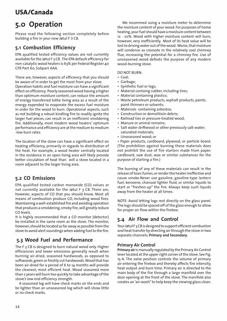
5.0 OperationPlease read the following section completely before building a fire in your new Jøtul F 3 CB.
5.1 Combustion EfficiencyEPA qualified tested efficiency values are not currently available for the Jøtul F 3 CB . The EPA default efficiency for non-catalytic wood heaters is 63% per Federal Register 40 CFR Part 60, Subpart AAA.
There are, however, aspects of efficiency that you should be aware of in order to get the most from your stove. Operation habits and fuel moisture can have a significant effect on efficiency. Poorly seasoned wood having a higher than optimum moisture content, can reduce the amount of energy transferred tothe living area as a result of the energy expended to evaporate the excess fuel moisture in order for the wood to burn. Operational aspects, such as not building a robust kindling fire to readily ignite the larger fuel pieces, can result in an inefficient smoldering fire. Additionally, most modern wood heaters’ optimum performance and efficiency are at the medium to medium -low burn rates.
The location of the stove can have a significant effect on heating efficiency, primarily in regards to distribution of the heat. For example, a wood heater centrally located in the residence in an open living area will likely provide better circulation of heat than will a stove located in a room adjacent to the larger living area.
5.2 CO EmissionsEPA qualified tested carbon monoxide (CO) values ar not currently available for the Jøtul F 3 CB. There are, however, aspects of CO that you should know. Most all means of combustion produce CO, including wood fires. Maintaining a well-established fire and avoiding operation that produces a smoldering, smoky fire, will greatly reduce CO levels. It is highly recommended that a CO monitor (detector) be installed in the same room as the stove. The monitor, however, should be located as far away as possible from the stove to avoid alert soundings when adding fuel to the fire.
5.3 Wood Fuel and PerformanceThe F 3 CB is designed to burn natural wood only. Higher efficiencies and lower emissions generally result when burning air-dried, seasoned hardwoods, as opposed to softwoods, green or freshly cut hardwoods. Wood that has been air-dried for a period of 6 to 14 months will provide the cleanest, most efficient heat. Wood seasoned more than 2 years will burn too quickly to take advantage of the stove’s low end efficiency strength. A seasoned log will have check marks on the ends and be lighter than an unseasoned log which will show little or no check marks.
We recommed using a moisture meter to determine the moisture content of your wood. For purposes of home heating, your fuel should have a moisture content between 12 - 20%. Wood with higher moisture content will burn, however, very inefficiently. Most of its heat value will be lost to driving water out of the wood. Worse, that moisture will condense as creosote in the relatively cool chimney flue, increasing the potential for a chimney fire. Use of unseasoned wood defeats the purpose of any modern wood-burning stove.
DO NOT BURN:• Coal;• Garbage;• Synthetic fuel or logs;• Material containg rubber, including tires;• Material containing plastics;• Waste petroleum products, asphalt products, paints, paint thinners or solvents;• Materials containing asbestos;• Construction or demolitioin debris;• Railroad ties or pressure-treated wood;• Manure or animal remains;• Salt water driftwood or other previously salt-water; saturated materials; • Unseasoned wood; or• Paper products, cardboard, plywood, or particle board. (The prohibition against burning these materials does not prohibit the use of fire starters made from paper, cardboard, saw dust, wax or similar substances for the purpose of starting a fire.)
The burning of any of these materials can result in the release of toxic fumes, or render the heater ineffective and cause smoke.Never use gasoline, gasoline-type lantern fuel, kerosene, charcoal lighter fluid, or similar liquids to start or “freshen-up” the fire. Always keep such liquids away from the heater at all times.
NOTE: Avoid letting logs rest directly on the glass panel. The logs should be spaced off of the glass enough to allow for proper air flow within the firebox.
5.4 Air Flow and ControlYour Jøtul F 3 CB is designed to support efficient combustion and heat transfer by directing air through the stove in two separate channels; Primary and Secondary.
Primary Air ControlPrimary air is manually regulated by the Primary Air Control lever located at the upper right corner of the stove. See Fig. 15-A. The valve position controls the volume of primary air entering the firebox and thereby affects fire intensity, heat output and burn time. Primary air is directed to the main body of the fire through a large manifold over the door opening at the front of the stove. The manifold also creates an ’air-wash” to help keep the viewing glass clean.

15
USA/CanadaSecondary air allows combustion of volatile gas and other by-products of primary combustion that would otherwise enter the atmosphere unburned. This unregulated air is preheated as it passes over the back of the stove and through a stainless steel manifold at the top of the firebox. This additional hot oxygen allows any unburned gasses to be burned inside the stove. The action of secondary combustion can be readily seen through the viewing glass a slow, rolling flames suspended over the main fuel bed and smaller jets of flame extending from the secondary manifold ports. At the same time, no smoke will be observed exiting the chimney. This is evidence that the stove is operating at the so-called ”sweet-spot” wherein optimum efficiency is realized.
Start-Up Air ControlThe start-up air control lever is located below the glass in the center of the front door. This control is for “start - up” air only and should not be used to freshen an existing fire or during refueling. Never leave the stove unattended while this control is open, overfiring could result, which can damage the appliance. See figure 15.-B.
Fig. 15A
B
Use a Stove-top ThermometerDetermining the primary air setting for the best overall performance for your particular needs and installation will be established over time through trial and error. Each installation has unique characteristics that will affect stove performance. Use a stove-top thermometer to monitor the status of the fire. Place the thermometer on the stove top, centered two one side or the other. See fig. 16. Generally speaking, once the stove temperature has reached 400°F - 600°F, the air control may be set in a mid-range position to allow adequate oxygen to support efficient combustion throughout the burn cycle.
Fig. 16
Stove top thermometer
5.5 Break-In ProcedureThe Jøtul F 3 CB is constructed of cast iron and stove furnace cement. Cast iron, while very durable, expands and contracts as it is heated and cooled. This type of construction requires the stove to be “broken-in” gradually so that thermal expansion does not occur too quickly. The following steps describe the proper break-in procedure for the Jøtul F 3 CB:1. Light a small fire of newspaper and kindling. Only al-
low the stove to reach a maximum surface tempera-ture of 200°F (93° C). Burn for approximately 1 hour.
2. Allow the stove to cool to room temperature.3. Light a second fire, allowing the stove to reach a
maximum temperature of 300°F (149°C) for 1 hour.4. Cool the stove to room temperature.5. Light a third fire and gradually allow the stove to
reach a surface temperature of 400°F (204°C).6. Cool stove to room temperature. This completes the
“break-in” procedure.
Note: Keep the stove under 400°F (204°C) surface temperature during any “break-in fire”, with the exception of the last “break-in” fire. If the temperature exceeds 400°F, move the primary air control lever all the way to the left to shut off the air supply completely. It is normal that the stove top temperature will continue to climb until the fuel burns down somewhat. Once the fire is out and the stove has cooled to room temperature, continue the break-in procedure. Never attempt to reduce the temperature by removing burning logs from the fire. NOTE: It is normal for a new painted stove to emit an odor and smoke during its first several fires. This is caused by the seasoning of the high temperature paint and will diminish with each fire. Opening a window or door to provide additional ventilation will alleviate this condition.

16
USA/Canada5.6 Starting and Maintaining a FireBurn only solid wood directly on the bottom grate of the stove. Do not elevate the fire in any way.
WARNING: THE ASH PAN DOOR MUST ALWAYS BE SECURELY CLOSED WHEN THE STOVE IS IN OPERATION. BURNING THE STOVE WITH THE ASH DOOR OPEN WILL PROMOTE UNEVEN THERMAL EXPANSION AND CAN RESULT IN DAMAGE TO THE STOVE AND VOID YOUR WARRANTY.
Traditional Fire Building 1. With both the primary and start-up air control levers
in the full open position (to the right), place several sheets of crumbled paper directly on the grate. On top of the newspaper, place several pieces of small dry kindling (approx. 1” in diameter) with two to three larger logs (approx. 3” to 5” in diameter) on top.
2. Light the fire and close the door, slowly building the fire by adding larger and larger logs. Be sure to follow the break-in procedure before creating a hot fire that might damage the stove.
3. Once the stove has reached a surface temperature range of between 400° and 600°, (204°C -316°C), adjust the primary air control lever as necessary to generate the heat output and burn time desired.
We recommend using a magnetic stove top ther-mometer to monitor the surface temperature of the stove. The optimum surface temperature range for the most efficient burn is between 400° and 600° (204°C -316°C). for the best locations to place a stove-top thermometer.
Top-Down Fire BuildingMany people find this method to be superior to the
traditional method.1. With both the primary and start-up air control levers
in the full open position (to the right), place two short 1/4-split logs on the firebox floor, perpendicular to the rear wall, about 6 inches apart.
2. Place kindling across the base logs.3. Place one or two smaller logs on top of the kindling.5. Place newspaper between the two bottom logs under
the kindling. Light the news paper and close the door. Continue to add kindling and small logs as necessary to build the fire. Keep the air control fully open until the fire is well-established.
WARNING: DO NOT OVERFIRE THIS HEATER. IF ANY PART OF THE STOVE OR CHIMNEY CONNECTOR GLOWS, YOU ARE OVERFIRING. A HOUSE FIRE OR SERIOUS DAMAGE TO THE STOVE OR CHIMNEY COULD RESULT.
ATTEMPTS TO ACHIEVE HEAT OUTPUT RATES THAT EXCEED HEATER DESIGN SPECIFICATIONS CAN RESULT IN PERMANENT DAMAGE TO THE HEATER.
Creosote and Soot Formation and the Need for RemovalWhen wood is burned slowly, it produces tar and other organic vapors which combine with expelled moisture to form creosote. These creosote vapors condense in the relatively cool chimney flue of a slow burning fire. The creosote that accumulates in the flue is highly flammable and is the fuel of chimney fires. To prevent a chimney fire, the creosote needs to be removed by sweeping the chimney and flue connector. The frequency of sweeping will depend on how you operate your stove. An accumulation of 1/4” or more on the sides of the flue or connector is considered hazardous and should be removed.
In the event that creosote in your chimney or flue connector ignites, the resulting fire is often accompanied by a roaring noise and a crackling sound as flakes of burned creosote break loose. lf you suspect you are having a chimney fire, immediately close the primary air control and make sure the stove door is closed. Call the fire department and get everyone safely out of the house.
Trying to extinguish the fire in the stove will not help. In fact it can make the matter worse by allowing more oxygen through the door, which then accelerates the fire in the chimney. When the roaring and crackling has stopped, you should resist the temptation to open the door and look at the fire. The fire may have suffocated, but could rekindle when you open the door. After a chimney fire, do not use your stove until the chimney and the flue connector has been cleaned and inspected to ensure that no damage has occurred.
5.7 Adding FuelWhen reloading the stove while it is still hot and a bed of hot embers still exists, follow this reloading procedure:• Always wear gloves when tending to the stove.• Place only the Primary Air Control in the full open
position (far right). The Start-up Air Control should be fully closed when the stove is operating.
• Wait a few seconds before opening the door.• Use a stove tool or poker to distribute the hot embers
equally around the firebox and away from the air inlet ports at the front center of the firebox floor.
• Load the fuel, usually with smaller logs first.• Close the door, be sure to latch the door tightly.• Wait 5 – 10 minutes before adjusting the air controls
to the desired heat output setting. (If you have at least a 2” thick ember bed when reloading, it may be possible to close the door and immediately adjust the air control setting).

17
USA/Canada
6.0 MaintenanceAsh removal: For your protection, always wear safety gloves when handling the ash pan.
Ash removal will be required periodically depending on how frequently the stove is used. Conveniently, the Jøtul F 3 CB is equipped with an ash pan assembly for easy ash removal, without the need for opening the front doors.
The ash pan door is located under the front ashlip of the stove. To open the ash door rotate the door knob counterclockwise to unlatch the door and clockwise to latch the door.
Remove the ash pan. When the stove is in operation always close the ash pan door before leaving to dispose of the ashes. The ashes should be placed in a metal container equipped with a tight sealing lid. The container should be placed on a noncombustible floor or on the ground, well away from all combustible materials, pending final disposal. If the ashes are disposed of by burial in soil or otherwise locally dispersed, they should be retained in the closed container until all cinders have thoroughly cooled.
Glass careCleaning: On occasion it will be necessary to clean the carbon deposits and fly ash off of the glass. If the carbon and fly ash are allowed to remain on the glass for an extended period of time it could eventually cause the glass to become etched and cloudy. Any creosote, which might deposit on the glass, will burn off during the next hot fire.
The proper cleaning procedure is as follows:1. Glass needs to be completely cool.2. Only use a cleaner that is specifically designed for this
purpose. The use of abrasives will damage the glass and ultimately leave the glass frosted.
3. Rinse and dry glass completely, before burning your stove.
Important: Replace glass only with a ceramic glass panel specifically designed for the Jøtul F 3. Do not use substitutes. Replacement glass panels can be ordered through your Jøtul dealer.
Glass removal: Always operate the doors slowly and cautiously to avoid cracking or breaking the glass. Never use the door to push wood into the firebox. If the glass becomes cracked or broken follow this procedure for replacement:
Never operate the stove with a cracked or broken glass panel.1. Remove the door from the stove and place on a flat
surface.2. Carefully remove all of the glass clips from the inside
of the door.3. Gently remove all pieces of the glass panel and
gasketing.4. Remove all remaining debris from the glass area using
a wire brush.5. Apply a small bead of gasket/stove cement and the new
gasket. Do not overlap the ends of the gasket rope.6. Center the new glass panel over the gasket and reinstall
the glass clips. See figure 17. Important: The side of the glass treated with an
infrared coating (marked on the perimeter) should always be facing outward. It is extremely important to tighten the glass clips slowly and in a repeating pattern, like tightening the lugs on an automobile wheel.
7. It may be necessary to retighten the glass clips after the stove has be burned and the gasketing has been seated.
Chimney SystemThe Jøtul F 3 CB is designed to burn cleanly and efficiently when used according to the guidelines in this manual. In order to maintain proper performance, you should inspect the chimney and chimney connector at the beginning of each heating season and then, every other month during the heating season. Clean the chimney whenever creosote and fly ash accumulation exceeds 1/4 inch in any part of the system.
Chimney brushes are available from your local Jøtul dealer or hardware supply store. Your dealer can also refer you to a reputable, professional chimney sweep who will have all the equipment to ensure a complete and proper job. Failure to keep the chimney system free of creosote and build up could result in a serious chimney fire.

18
USA/Canada
7.0 General MaintenanceAs with your car, regular maintenance will prolong the life of your stove and ensure satisfactory performance.
The following procedures do not take long and are generally inexpensive, but when done consistently, increase the life of your appliance and in turn, increase your years of enjoyment.
Enamel Care• DO NOT ATTEMPT TO CLEAN HOT ENAMEL SURFACES.
Clean only cold enamel surfaces with a soft damp cloth and polish with a clean dry cloth. Most stains can be removed with a solution of baking soda and vinegar. Let this solution sit on the stain for a min-ute or two before rubbing it dry with a damp cloth. Organic cleaning commercial cleaning solutions, such as Citra-Solv®, can also be effective.
• DO NOT USE SOAPY OR ABRASIVE SOLUTIONS. These can cause stains. Coffee, tea, and fruit jucies will also cause stains.
• AVOID CONTACT WITH METAL OBJECTS. Trivets, ket-tles, or pots, can damage the enamel.
Annual Inspection• Empty stove of all soot and ashes. Only use a vacuum
for this job if the vacuum is specifically designed for ashes.
• Inspect the stove seams. Use a utility light to inspect the stove inside and out for cracks or leaks. Replace all cracked parts and repair any cement leaks with furnace cement.
Fig. 17
DoorGasketGlass
Glass clips
GasketsDoor and glass panel gaskets will harden and compress with over time. Inspect and replace if necessary. Use Universal Gasket Kit 157050, available from your local Jøtul Authorized Dealer.Check the door gasket for tightness. Close and latch the doors on a dollar bill and slowly try to pull the dollar bill free. If it can be easily removed then the seal is too loose.
Check several spots around the door, and repeat the procedure on the ash pan door as well.
Gasket Replacement1. Use pliers and a putty knife to remove the old gasket from
the door. 2. Thoroughly clean the channel with a wire brush. 3. Apply a small bead of cement to the channel. 4. Gently press the new gasket into the cement to seat it in the
channel. Close and latch the door and then reopen. Wipe any excess cement squeezed out from around the gasket.
Gasket list for the Jøtul F 3 CBDescription Order # Size Length Top plate gasket 100038 3/8” ld 6’ Ash housing gasket 128213 sheet gasket Ash door gasket 200024 1/4” ld 3’ Glass gasket 200028 1/4” ld 3’6” Door gasket 200024 11/32” ld 5’ Air manifold Gasket 200028 3/16” 16”
19
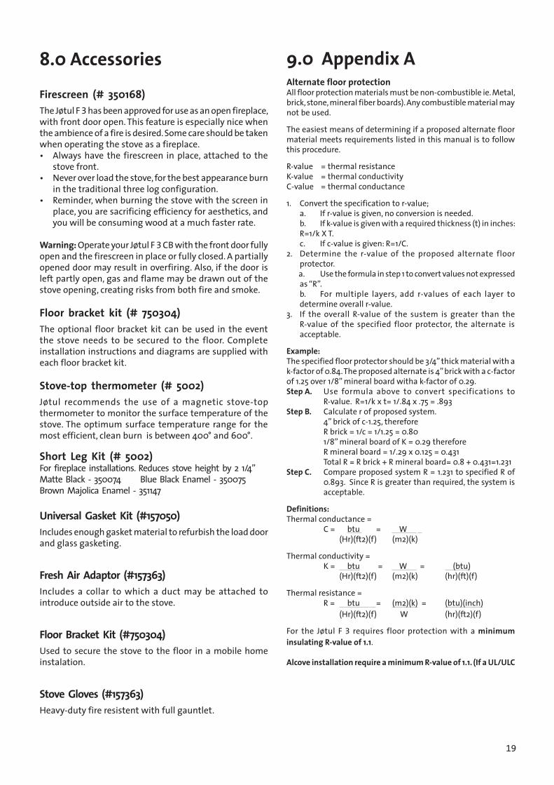
9.0 Appendix AAlternate floor protectionAll floor protection materials must be non-combustible ie. Metal, brick, stone, mineral fiber boards). Any combustible material may not be used.
The easiest means of determining if a proposed alternate floor material meets requirements listed in this manual is to follow this procedure.
R-value = thermal resistanceK-value = thermal conductivityC-value = thermal conductance
1. Convert the specification to r-value; a. If r-value is given, no conversion is needed. b. If k-value is given with a required thickness (t) in inches:
R=1/k X T. c. If c-value is given: R=1/C.2. Determine the r-value of the proposed alternate floor
protector. a. Use the formula in step 1 to convert values not expressed
as “R”. b. For multiple layers, add r-values of each layer to
determine overall r-value.3. If the overall R-value of the sustem is greater than the
R-value of the specified floor protector, the alternate is acceptable.
Example:The specified floor protector should be 3/4” thick material with a k-factor of 0.84. The proposed alternate is 4” brick with a c-factor of 1.25 over 1/8” mineral board witha k-factor of 0.29. Step A. Use formula above to convert specifications to
R-value. R=1/k x t= 1/.84 x .75 = .893Step B. Calculate r of proposed system. 4” brick of c-1.25, therefore R brick = 1/c = 1/1.25 = 0.80 1/8” mineral board of K = 0.29 therefore R mineral board = 1/.29 x 0.125 = 0.431 Total R = R brick + R mineral board= 0.8 + 0.431=1.231Step C. Compare proposed system R = 1.231 to specified R of
0.893. Since R is greater than required, the system is acceptable.
Definitions:Thermal conductance = C = btu = W (Hr)(ft2)(f) (m2)(k)
Thermal conductivity = K = btu = W = (btu) (Hr)(ft2)(f) (m2)(k) (hr)(ft)(f)
Thermal resistance = R = btu = (m2)(k) = (btu)(inch) (Hr)(ft2)(f) W (hr)(ft2)(f)
For the Jøtul F 3 requires floor protection with a minimum insulating R-value of 1.1.
Alcove installation require a minimum R-value of 1.1. (If a UL/ULC
8.0 Accessories
Firescreen (# 350168)The Jøtul F 3 has been approved for use as an open fireplace, with front door open. This feature is especially nice when the ambience of a fire is desired. Some care should be taken when operating the stove as a fireplace. • Always have the firescreen in place, attached to the
stove front.• Never over load the stove, for the best appearance burn
in the traditional three log configuration.• Reminder, when burning the stove with the screen in
place, you are sacrificing efficiency for aesthetics, and you will be consuming wood at a much faster rate.
Warning: Operate your Jøtul F 3 CB with the front door fully open and the firescreen in place or fully closed. A partially opened door may result in overfiring. Also, if the door is left partly open, gas and flame may be drawn out of the stove opening, creating risks from both fire and smoke.
Floor bracket kit (# 750304)The optional floor bracket kit can be used in the event the stove needs to be secured to the floor. Complete installation instructions and diagrams are supplied with each floor bracket kit.
Stove-top thermometer (# 5002)Jøtul recommends the use of a magnetic stove-top thermometer to monitor the surface temperature of the stove. The optimum surface temperature range for the most efficient, clean burn is between 400° and 600°.
Short Leg Kit (# 5002) For fireplace installations. Reduces stove height by 2 1/4” Matte Black - 350074 Blue Black Enamel - 350075 Brown Majolica Enamel - 351147
Universal Gasket Kit (#157050)Includes enough gasket material to refurbish the load door and glass gasketing.
Fresh Air Adaptor (#157363)Includes a collar to which a duct may be attached to introduce outside air to the stove.
Floor Bracket Kit (#750304)Used to secure the stove to the floor in a mobile home instalation.
Stove Gloves (#157363)Heavy-duty fire resistent with full gauntlet.
20
USA/Canada
JĂTUL
78
8586
7776
7574
73
5059
2257
5083 826163 62
4521
5552
5149
4644
43
2 2b1
358
4
76
512
98
1615
4
42
39 414038373533 3431 323026 28 2927523 24
1817
5 22
65 70
72
71464
81
60
5 710 5
1319
1420
1150
4
48
79
79
84
313.
0
8788
89
66 69 4
90 91 92 93 94 95
2c 2d
2e
9697
98
Part
list F
3 /
F3 U
SA
JØTU
L A
SFr
edrik
stad
, Nor
way
Tegn
ing
nr: 1
-133
1-P1
3D
ate
Oct
11

21
USA/Canada
No Description, Dim./Spec.1 Nut brass, M6x20 DIN 15872 Heat shield aluz. f/ivory en. 2 b Heat shield 3 Screw, M6x16 DIN 9654 Nut , M6 DIN 9345 Screw collar, M6x16 st.5.6 ubeh.6 Cover smoke outlet rear 7 Traverse bar to cover smoke outlet rear 8 Top plate compl. w/ cover smoke outlet 9 Gasket, LD 375-2 9.5x180010 Cover smoke outlet side 11 Baffle plate 12 Air distributor USA 13 Cover smoke outlet top 14 Traverse/cover smoke outlet top 15 Back plate 16 Screw, M6x35 st.5.6 ubeh17 Gasket, LD 360 M/L Ø8.7x15018 Gasket, LD 360 M/L Ø8.7x56019 Gasket, LD 250-2 M/L Ø6,4x54020 Cast iron washer 21 Screw, M8x20 st.8.822 Side plate 23 Burn plate, back 24 Burn plate right 26 Air deflektor 27 Gasket, LD 187-1 M/L 4.8x41028 Sliding vent 29 Front plate 30 Washer, Ø12x6x0.531 Log retainer. 32 Screw, M6x8 poz33 Glass clip w\ gasket 34 Gasket, LD 360 Ø8.7x148035 Door compl. w/o glass 37 Hinge pin, Ø0,6x3338 Ignition vent 39 Washer, D nr. 53124140 Cover/ign. vent 41 Screw/collar, M6x12 st. 8.8 ubeh.42 Handle compl., nickel-plated 43 Locking bar 44 Gasket, LD 187 m\l Ø4,8x180045 Glass , 358 x 233 mm46 Spark screen 48 Spring 49 Knob, plastic, 0,30mm M650 Screw collar, M6x16 st. 5.6 51 Ash lip 52 Leg 53 Skrew M6x20 ST 8,8 ubeh.54 Washer, Ø18x0,6, 4x155 Bottom plate, 57 Inner bottom plate 58 Screw sink head, M6x25 sortkrom.poz. (black-poz.)
59 Burn plate left 60 Insulation, Firemaster blanket (after X-607)61 Screw , M8x25 st.8.862 Cover/sec. air inlet, 63 Screw sinkhead, M6x40 poz DIN 96564 Gasket-flat 65 Ash house w\ heat shield and hinge (after 1998)66 Hinge, ash house (before 1998)69 Screw sh Pozid, M6x10 DIN 965 (before 1998)70 Ash box, 1mm steel plate71 Hinge pin, Ø6x10072 Locking screw, M6x10 DIN91573 Handle for ashdoor 74 Handle stub 75 Spring 76 Door ashroom complete, 77 Gasket, LD 250-2 Ø6.4x73078 Door latch 79 Gasket, LD 250 m\l Ø6,4x60081 Hexagon nut, M8 DIN 93482 Locking pin, M6x20 DIN 91483 Fixing bracket 84 Air blocker (for USA) 85 Heat shield rear (for Germany)86 Heat shield under (for Germany)87 Extention nut for heat shield, rear (for Germany)
M6x18mm88 Distance sleeve for heatshield, under (for Germany)
Ø10xØ6,2x15mm89 Self closing mechanism (for Germany)90 Nut , M10 DIN 93491 Door latch, 3mm stainless steel92 Spring Ø10 inside, 2mm stainless steel93 latch bolt ash door, Steel94 Wooden knob, Hard wood95 Skrew, M6x60 DIN 8496 Cast iron flue collar97 Screw, M6 x 60 mm countersunk PH, 298 Flue Collar Cross Bar
1-1331-P23
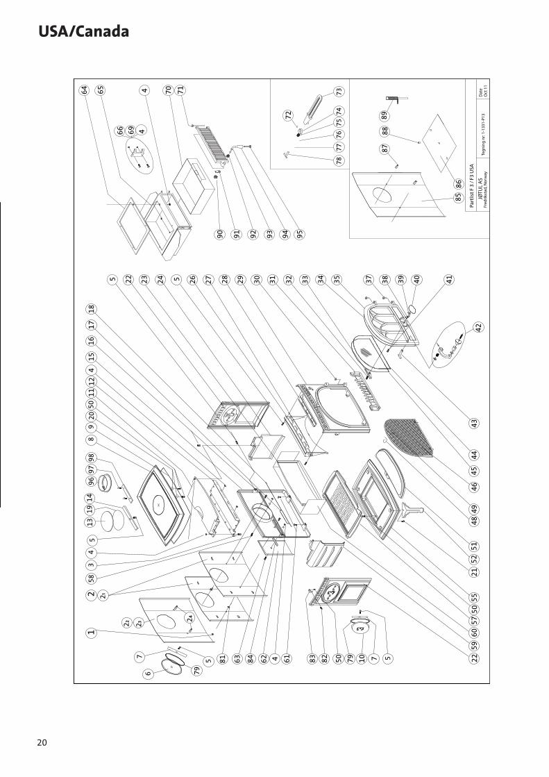
Only use replacements parts provided through your authorized Jøtul dealer.
10.0 Illustrated Part List for Jøtul F 3 CB
22
11.0 Jøtul Woodstove Limited Lifetime WarrantyEffective January 1, 2013
This warranty policy applies to wood-burning products identified by Jøtul and Scan trade names, as set forth below.
A. LIMITED LIFETIME WARRANTY, parts only:Jøtul North America Inc. (JØTUL) warrants, to the original retail purchaser, that those baffle and air manifold components of the Jøtul or Scan Stove or Fireplace Insert specified above will be free of defects in material and workmanship for the life of the product. This warranty is subject to the terms, exclusions and limitations set forth below.
B. LIMITED FIVE YEAR WARRANTY - Cast Iron and Steel Components:JØTUL warrants, to the original retail purchaser, that those components of the Jøtul or Scan Stove or Fireplace Insert specified above will be free of defects in material and workmanship for a period of five (5) years from the date of purchase. This warranty is subject to the terms, exclusions and limitations set forth below.
C. LIMITED TWO YEAR WARRANTY - Enamel Finish: JØTUL warrants, to the original retail purchaser, the enamel finish on cast iron components of the Jøtul Stove or Fireplace Insert specified above against peeling or fading for a period of two (2) years from the date of purchase. This warranty is subject to the terms, exclusions and limitations set forth below.
D. LIMITED ONE YEAR WARRANTY - Electrical Components (blowers, thermostatic switches): JØTUL warrants, to the original retail purchaser, that those components of the Jøtul or Scan Stove or Fireplace Insert specified above will be free of defects in material and workmanship for a period of one (1) year from the date of purchase. This warranty is subject to the terms, exclusions, and limitations set forth below:
JØTUL will repair or replace, at its option, any of the above components determined by JØTUL to be covered by this warranty. You must, at your own expense, arrange to deliver or ship the component to an authorized Jøtul
or Scan dealer and arrange for pickup or delivery of the component after repairs have been made. If, upon inspection, JØTUL determines that the component is covered by this warranty, the repair or replacement will be made as set forth above. This warranty is not transferable and is extended only to, and is solely for the benefit of, the original retail purchaser of the Jøtul or Scan Stove or Fireplace Insert. This paragraph sets forth the sole remedy available under this warranty in the event of any defect in the Jøtul Scan Stove or Fireplace Insert.
The warranty period for any replaced component will be the remaining unexpired portion of the warranty period for the original component.
Please retain your dated sales receipt in your records as proof of purchase.
EXCLUSIONS AND LIMITATIONSNOTICE: This warranty is void if installation or service is performed by someone other than an authorized installer or service agency, or if installation is not in conformance with the installation and operating instructions contained in this owner’s manual or local and/or national fire and building regulations. A listing of local authorized installers, service agencies and gas suppliers can be obtained from the National Fireplace Institute at http://www.nficertified.org/. This warranty does not cover the following:1. Repair or replacement of parts that are subject to
normal wear and tear during the warranty period or to parts that may require replacement in connection with normal maintenance. These parts include paint, gaskets, burn plates, ceramic insulation blankets, skamol baffles and panels, firebricks, fire grates, or glass (Ceramic glass is warranted against thermal breakage only).
2. Damage due to incorrect installations not in conformance with the installation instructions contained in this owner’s manual or local and/or national fire and building regulations.
3. Damage, including damage to enamel surfaces, caused by improper operation, over-firing, and/or misuse. Improper operation, such as burning the stove with the ash door open, can damage the stove. Over-firing occurs when any part of the stove glows red. Over-firing can also be identified by warped plates, rust-colored cast iron, paint pigment that has turned dusty white, or bubbling, cracking and discoloration of the enamel finish. Misuse includes, without limitation, use that is not in conformance with the operating instructions contained in this owner’s manual.
4. Damage to enamel finish including chipping, mechanical or chemical abrasion, crazing, staining, or rust caused by high humidity or salt air environments.
5. Damage from or repair of rust. Use of a stove-top steamer can cause rust.
USA/Canada
23
6. Damage due to service performed by an installer or service agency, unless otherwise agreed to in writing by JØTUL.
7. Damage caused by unauthorized modification, use or repair.
8. Costs incurred by travel time and/or loss of service.9. Labor or other costs associated with the repair of
components beyond the warranty period.10. Damage incurred while the Jøtul or Scan Stove or
Fireplace is in transit.
IN NO EVENT SHALL JØTUL, ITS PARENT COMPANY, SHAREHOLDERS, AFFILIATES, OFFICERS, EMPLOYEES, AGENTS OR REPRESENTATIVES BE LIABLE OR RESPONSIBLE TO YOU FOR ANY SPECIAL, INDIRECT, INCIDENTAL, CONSEQUENTIAL, PUNITIVE OR OTHER SIMILAR DAMAGES, INCLUDING, BUT NOT LIMITED TO, LOST PROFITS, LOST SALES, INJURY TO PERSON OR PROPERTY, OR DAMAGES TO A STRUCTURE OR ITS CONTENTS, ARISING UNDER ANY THEORY OF LAW WHATSOEVER. ALL IMPLIED WARRANTIES, INCLUDING THE IMPLIED WARRANTIES OF MERCHANTABILITY AND FITNESS FOR A PARTICULAR PURPOSE, OR OTHERWISE, ARE LIMITED IN DURATION TO THE LENGTH OF THIS WRITTEN WARRANTY. EXCEPT AS EXPRESSLY SET FORTH HEREIN, JØTUL MAKES NO ORAL, WRITTEN OR OTHER WARRANTY WITH RESPECT TO JØTUL OR SCAN STOVES OR FIREPLACES.
Some states do not allow the exclusion or limitation of incidental or consequential damages, or limitations on the length of implied warranties. Therefore, the above exclusions or limitations may not apply to you. This warranty gives you specific legal rights, and you may have other rights, which vary from state to state.
JØTUL reserves the right to discontinue, modify or change the materials used to produce the Jøtul or Scan Stove or Fireplace Insert. JØTUL shall have the right to replace any defective component with substitute components determined by JØTUL to be of substantially equal quality and price.
The dollar value of JØTUL’s liability for breach of this warranty shall be limited exclusively to the cost of furnishing a replacement component. JØTUL may at its discretion discharge all obligations by refunding the wholesale price of any defective part or appliance. JØTUL shall in no event be liable for any special, indirect or consequential damage of any nature which is in excess of the original wholesale purchase price of the product. JØTUL shall not in any event be liable for the cost of labor expended by others in connection with any defective component. Any costs or expenses beyond those expressly assumed by JØTUL under the terms of this warranty shall be the sole responsibility of the owner(s) of the Jøtul Stove or Fireplace.
No dealer, distributor, or other person is authorized to modify, augment, or extend this limited warranty on behalf of JØTUL. NO MODIFICATION OR CHANGE TO THIS WARRANTY WILL BE EFFECTIVE UNLESS IT IS MADE IN A WRITTEN DOCUMENT MANUALLY SIGNED BY AN
USA/CanadaAUTHORIZED OFFICER OF JØTUL.
An authorized installer may have been provided with certain information related particularly to the Jøtul or Scan Stove or Fireplace; however, no authorized installer or other person who may service the appliance is an agent of JØTUL. No inference should be made that JØTUL has tested, certified, or otherwise pronounced any person as qualified to install or service the appliance. JØTUL shall not be liable or otherwise responsible for any error or omission by a person installing or servicing a Jøtul or Scan Stove or Fireplace Insert.
If you believe your Jøtul or Scan Stove or Fireplace Insert is defective, you should contact your nearest authorized Jøtul dealer, who will process a warranty claim. IN ORDER TO QUALIFY FOR WARRANTY COVERAGE, JØTUL MUST RECEIVE NOTICE OF A POSSIBLE DEFECT WITHIN SIXTY (60) DAYS OF THE DATE THE DEFECT IS FIRST DISCOVERED, OR REASONABLY COULD HAVE BEEN DISCOVERED.
This warranty is given by Jøtul North America, Inc., 55 Hutcherson Drive, Gorham, Maine 04038 USA

24
Jøtul pursues a policy of continuous product development. Products supplied may therefore differ in specification, colour and type of accessories from those illustrated and described in the brochure.
Jøtul vise sans cesse à améliorer ses produits. C’est pourquoi, il se réserve le droit de modifier les specifications, couleurs et équipements sans avis prélable.
QualityJøtul AS has a quality system that conforms to NS-EN ISO 9001 for product development, manufacturing, and distribution of stoves and fireplaces. This policy gives our customers quality and safety piece of mind as a result of Jøtul’s vast experience dating back to when the company first started in 1853.We appreciate your trust in welcoming our product into your home and invite your comment and appraisal of our efforts to provide you with the finest in home hearth products.
Qualité Le système de contrôle de la qualité de Jøtul AS est conforme à la norme NS-EN ISO 9001 relative à la conception, à la fabrication et à la distribution de poêles, foyers et inserts. Cette politique nous permet d’offrir à nos clients une qualité et une sécurité reposant sur la vaste expérience accumulée par Jøtul depuis sa création en 1853.
Art. no 10024372-P14
Jøtul AS, May, 2015
Jøtul North America Inc55 Hutcherson DriveGorham, Maine 04038, USA
Jøtul AS, P.o. box 1411N-1602 Fredrikstad, Norwaywww.jotul.com