Jøtul F 118 Black Bear - Acme Stove · Jøtul F 118 Black Bear for the United States and Canada...
24
Jøtul F 118 Black Bear for the United States and Canada Installation and Operating Instructions Jøtul F 118 Black Bear “I built me a flame late one night. When day is done, God will my flame never die” Viking proverb translated from the Old Nørse cast into the front plate. The Jøtul F 118 Black Bear fireplace insert is listed to burn solid wood only. Do not burn any other fuels. Read this entire manual before you install and use this appliance. Save these instructions for future reference and make them available to anyone using or servicing the fireplace insert. This wood heater requires periodic inspection and repair for proper operation. See this manual for specific maintenance information. It is against federal regulations to operate this wood heater in a manner inconsistent with the operating instructions in this owner’s manual.
Transcript of Jøtul F 118 Black Bear - Acme Stove · Jøtul F 118 Black Bear for the United States and Canada...

Jøtul F 118 Black Bear for the United States and Canada
Installation and Operating Instructions
Jøtul F 118 Black Bear
“I built me a flame late one night. When day is done, God will my flame never die”
Viking proverb translated from the Old Nørse cast into the front plate.
� The Jøtul F 118 Black Bear fireplace insert is listed to burn solid wood only. Do not burn any other fuels.
� Read this entire manual before you install and use this appliance.
� Save these instructions for future reference and make them available to anyone using or servicing the fireplace insert.
� This wood heater requires periodic inspection and repair for proper operation. See this manual for specific maintenance information. It is against federal regulations to operate this wood heater in a manner inconsistent with the operating instructions in this owner’s manual.

Jøtul F 118 Black Bear 5/17
2
Table of ContentsAccessories ............................................................................... 2 Standards and Safety Notices Standards .................................................................................... 3 Combustion Specifications ..................................................... 4 Building Codes ........................................................................... 4 Safety Notices ............................................................................. 5
1.0 Installation1.1. Assembly Before Installation ............................................. 51.2 Flue Collar Installation ......................................................... 51.3 Heat Shield Installation ....................................................... 61.4 Door Knob Installation ........................................................ 61.5 Chimney Connector .............................................................. 6
2.0 Chimney Requirements2.1 Masonry Chimneys .............................................................. 72.2 Prefabricated Chimneys ...................................................... 72.3 Chimney Height .................................................................... 82.4 Wall Pass-Throughs .............................................................. 8
3.0 Connecting to the Chimney3.1 Masonry Chimneys .............................................................. 93.2 Hearthmount into a Masonry Fireplace .......................... 93.3 Prefabricated Chimneys ...................................................... 10
4.0 Clearances to Combustibles4.1 Floor Protection ..................................................................... 104.2 Clearances to Walls and Ceilings ...................................... 11 4.3 Using Shields to Reduce Clearances ................................. 114.4 Alcove Installation ................................................................ 114.5 Clearance Specification Chart ........................................... 124.6 Clearance Diagrams .............................................................. 13
5.0 Operation5.1 Combustion Efficiency ......................................................... 145.2 CO Emissions .......................................................................... 145.3 Wood Fuel and Stove Performance .................................. 145.4 How Your Stove Works ......................................................... 15 5.5 Control Functions .................................................................. 155.6 Break-in Procedure ................................................................ 165.7 Starting and Maintaining a Fire ........................................ 16 5.8 Adding Fuel ............................................................................. 165.9 Open Door Fire-viewing ...................................................... 17 5.10 Creosote Accumulation ..................................................... 17 5.11 Ash Removal ......................................................................... 17
6.0 Maintenance6.1 Glass Care ................................................................................ 186.2 Glass Removal or Replacement ......................................... 186.3 General Care ........................................................................... 186.4 Gaskets .................................................................................... 186.5 Gasket Replacement ............................................................ 196.6 Chimney System ................................................................... 19 7.0 Illustrated Parts List .................................................................. 20,21
8.0 Warranty ............................................................................. 22
PLEASE NOTE:IT IS NORMAL FOR SMOKE AND ODOR TO OCCUR DURING THE INITIAL STAGES OF OPERATION, DEPENDING UPON TEMPERATURES GENERATED OVER TIME. THIS “CURING” CONDITION CAN BE ALLEVIATED BY PROMOTING FRESH AIR CIRCULATION WITHIN THE IMMEDIATE VICINITY OF THE APPLIANCE. SEE PAGE 16 FOR DETAILS.

3
Jøtul F 118 Black Bear 5/17
����������
���������������� �
��������� ���
����������
����������������� ���������� ���
����������
��������������
���������������� �� �������
���������
�� ����� �� �������
����������������������
����������
������������
��������������
��
��
����������
������������
StandardsThe Jøtul F 118 woodstove has been tested and listed to: U.S: ANSI/UL 1482 and ANSI/UL 737 Canada: CAN/ULC-S627-M00 CAN/ULC-S628-M93
Certified Safety Tests performed by ITS, Intertek Testing Services Middleton, WI
Manufactured by: Jøtul North America 55 Hutcherson Drive Gorham, Maine 04038-2644 (207) 591-6601
A French language version of fhis manual is available to download at www. jotul. ca.
Télécharger la version française de ce manuel à l’adresse www. jotul.ca.
F 118 Black Bear Dimensions
This heater meets the 2015 U.S. Environmental Protection Agency’s
emission limits for wood heaters manufactured after May 15, 2015.
This model heater may not be sold after May 15, 2020.
WARNING !THIS WOOD HEATER HAS A MANUFACTURER-SET MINIMUM LOW BURN RATE THAT MUST NOT BE ALTERED. IT IS AGAINST FEDERAL REGULATIONS TO ALTER THIS SETTING OR OTHERWISE OPERATE THIS WOOD HEATER IN A MANNER INCONSISTENT WITH OPERATING INSTRUCTIONS IN THIS MANUAL.
Jøtul F 118 Black Bear 5/17
4
Check Building CodesYour city, town, county or province may require a building permit to install a solid fuel burning appliance.
In the U.S., the National Fire Protection Association’s Code, NFPA 211, Standards for Chimneys, Fireplaces, Vents and Solid Fuel Burning Appliances, or similar regulations, may apply to the installation of a solid fuel burning appliance in your area.
In Canada, the guideline is established by the CSA Standard, CAN/CSA-B365-M93, Installation Code for Solid-Fuel-Burning Appliances and Equipment.
Always consult your local building inspector or authority having jurisdiction to determine what regulations apply in your area. Any requirement by the local authority having jurisdiction that is not specifically addressed in this manual, defaults to NFPA 211, and local codes in the U.S. or in Canada, CAN/CSA-B365-M and local codes. Your local officials have final authority in determining if a proposed installation is acceptable.
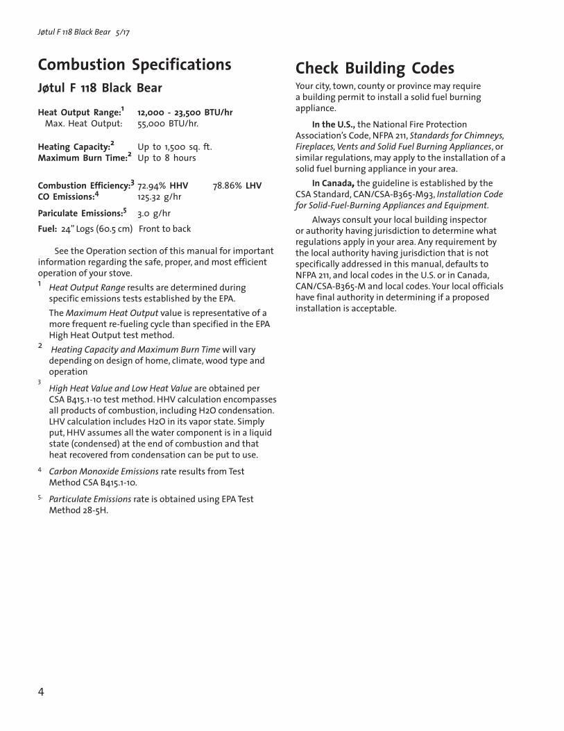
Combustion Specifications Jøtul F 118 Black Bear
Heat Output Range:1 12,000 - 23,500 BTU/hr Max. Heat Output: 55,000 BTU/hr.
Heating Capacity:2 Up to 1,500 sq. ft. Maximum Burn Time:2 Up to 8 hours
Combustion Efficiency:3 72.94% HHV 78.86% LHV CO Emissions:4 125.32 g/hr
Pariculate Emissions:5 3.0 g/hrFuel: 24” Logs (60.5 cm) Front to back
See the Operation section of this manual for important information regarding the safe, proper, and most efficient operation of your stove.1 Heat Output Range results are determined during
specific emissions tests established by the EPA. The Maximum Heat Output value is representative of a
more frequent re-fueling cycle than specified in the EPA High Heat Output test method.
2 Heating Capacity and Maximum Burn Time will vary depending on design of home, climate, wood type and operation
3 High Heat Value and Low Heat Value are obtained per
CSA B415.1-10 test method. HHV calculation encompasses all products of combustion, including H2O condensation. LHV calculation includes H2O in its vapor state. Simply put, HHV assumes all the water component is in a liquid state (condensed) at the end of combustion and that heat recovered from condensation can be put to use.
4 Carbon Monoxide Emissions rate results from Test Method CSA B415.1-10.
5. Particulate Emissions rate is obtained using EPA Test Method 28-5H.

5
Jøtul F 118 Black Bear 5/17
Safety Notices• Burn solid wood fuel only. Do not burn other fuels.
• Do not use chemicals or fluids to start the fire. Do not burn garbage or flammable fluids.
• If this room heater is not properly installed, a house fire may result. To reduce the risk of fire, follow the installation instructions. Failure to follow these instructions may result in property damage, bodily injury, or loss of life.
• Contact the local building or fire officials about restrictions and installation inspection requirements in your area.
• Do not connect this stove to any air distribution duct or system.
• Extremely hot while in operation! Keep children, clothing and furniture away. Contact will cause skin burns.
• Install smoke detectors in the living areas and bedrooms of your home. Test them regularly and install new batteries twice annually.
When installed in the same room as the stove, a smoke detector should be located as far from the stove as possible to prevent it from sounding when adding fuel to the fire.
• Avoid creating a low pressure condition in the room where the stove is operating. Be aware that operation of an exhaust fan or clothes dryer can create a low pressure area and consequently promote flow reversal through the stove and chimney system. The chimney and building, however, always work together as a system - provision of outside air, directly or indirectly to an atmospherically vented appliance will not guarantee proper chimney performance. Consult your local Jøtul authorized dealer regarding specific installation/performance issues.
• Jøtul recommends that this stove be installed by a professional solid fuel technician or that you consult one if you do the work yourself. Also, consult your insurance company regarding any other specific requirements.
1.0 Installation.
1.1 Assembly Before Installation
Unpack the StoveInspect the stove for damage. Contact your dealer immediately if any damage is found. Do not install the stove if any damage is evident.
Contents:• 6” Pipe Adaptor • Door Handle Knob and hardware • Pipe Adaptor Screws, M6x16 Hex Hd (2) • 3 mm hex key
1.2 Flue Collar InstallationAs built, the Flue Collar is oriented in the Rear Exit position.
Follow this procedure to change the collar to a Top Exit or Side Exit position if appropriate. You will need a 10 mm open end wrench or socket wrench.1. Reach through the flue collar opening and remove the
two 10 mm bolts that secure it to the rear panel. 2. Remove the two 10 mm bolts that secure the Cover
Plate to either the Top or Side Plate as desired.3. Re-install the Flue Collar on the appropriate position
and attach the Cover Plate to the rear panel using the screws previously removed.

Jøtul F 118 Black Bear 5/17
6
1.3 Heat Shield InstallationConsult Section 4 to determine whether or not a heat shield should be installed.The Rear and Side shields are perforated to enable you to use tin snips to remove material to accommodate the Flue Collar position your installation requires. Rear Heat Shield:
1. Remove the set screw located at the center of the stove back plate using the 3 mm hex key included with your stove.
2. Engage the heat shield stand-offs with the slot at each side of the back plate and attach the shield to the center hole using the M6 x 45 hex bolt supplied. See fig. 1.
Side Heat Shield:
1. Use a 10 mm wrench to loosen the two mounting bolts located under the lip of the stove bottom. See fig. 2.
2. Insert the stand-off clips, (attached to the backside of the shield), under the lip of the stove Shoulder Plate and engage the slots in the lower flange with the mounting screws. Tighten the screws.
Bottom Heat Shield: The bottom heat shield is pre-installed and must be used unless the stove hearth is composed of poured concrete on earth.
1.4 Assemble the Door Knob1. Locate the white washer between the handle and the
knob and attach to the door latch as shown in fig. 3.
1.5 Chimney ConnectorUse 6” single wall or listed 6” double-wall stovepipe to connect the stove to the chimney. Single wall stovepipe must be black iron or stainless steel and have a minimum thickness of 24 gauge. Do not use aluminum or galvanized steel pipe for chimney connection - these materials are not suitable for use with solid fuel.
Follow these guidelines regarding chimney connector construction:
• Do not use chimney connector as a chimney. It is intended only as a connection device.
• Each connector section must be oriented with the male (crimped) end pointing toward the stove. See fig. 4.
• Secure all connector joints with three sheet metal screws. The connection to the stove flue collar uses the two M6x 16 mm self-tapping screws provided.
�����������
������������ ����
Figure 4. Chimney connector orientation.
Figure 1. Install the Rear Heat Shield.
Cut out section for rear exit flue collar
Figure 2. Install the Side Heat Shield.
Shoulder Plate
Figure 3. Load Door latch assembly.

7
Jøtul F 118 Black Bear 5/17
The following guidelines give the necessary chimney requirements based on the national code (ANSI-NFPA 211 for the US. And CSA CAN-B365 for Canada). However, many local codes differ from the national code to take into account climate, altitude, or other factors. Your local building inspector is the final approving authority. Consult them prior to installation.
Do not connect the stove to any air distribution duct or system.
2.1 Masonry ChimneysFollow these guidelines when installing the Jøtul F 118 into a masonry fireplace:
• The masonry chimney must have a fireclay liner or equivalent, with a minimum thickness of 5/8” (14 mm) and must be installed with refractory mortar. There must be at least 1/2” (12.7 mm) air space between the flue liner and chimney wall.
• The fireclay flue liner must have a nominal size of 8” X 8” (20 cm x 20 cm), and should not be larger than 8”X 12” (20 cm x 30 cm). A round fireclay liner must have a minimum inside diameter of 6” (15 cm) and maximum inside diameter of 8” (20 cm). A larger chimney should be relined with an appropriate code approved liner.
• Brick or modular block must be a minimum of 4” (10 cm) nominal thickness. Stone construction must be at least 12” (30 cm) thick.
• A newly-built chimney must conform to local codes, or, in their absence, must comply with national regulations.
• An existing chimney must be inspected by a professional, licensed chimney sweep, fire official, or code officer to ensure that the chimney is in proper working order. Any repairs must be completed before installing the stove.
• No other appliance may be vented into the same flue.
• An airtight clean-out door should be located at the base of the chimney.
2.2 Prefabricated ChimneysA prefabricated metal chimney must be tested and listed for use with solid fuel burning appliances. High Temperature (HT) Chimney Standard UL 103 for the U.S. and High Temperature Standard ULC S-629 for Canada.
The manufacturer’s installation instructions must be followed precisely. Always maintain the proper clearance to combustibles as established by the pipe manufacturer. This clearance is usually a minimum of 2”, although it may vary by manufacturer or for certain chimney components.
• For the best performance, the chimney connector should be as short and direct as possible, including no more than two 90° elbows.
• The maximum vertical run of single wall stovepipe should not exceed 10 ft. (305 cm).
• The maximum horizontal run should not exceed 3 ft. (92 cm) with a 1/4” rise per foot. Under no circumstance should horizontal pipe be allowed to slant down toward the chimney.
• No part of the chimney connector may pass through an attic or roof space, closet or other concealed space, or through a floor or ceiling. All sections of the chimney connectors must be accessible for cleaning. Where passage through a wall or partition of combustible construction is desired, the installation must conform with NFPA 211 or CAN/CSA-B365, and is also addressed in this manual.
• Do not connect this stove to a chimney flue serving another appliance.
2.0 Chimney RequirementsThere are two types of approved chimneys:
1. A code-approved masonry chimney with a ceramic tile or listed steel flue liner.
2. A prefabricated chimney complying with the requirements for Type HT (2100°F) chimneys per UL 103 or ULC S629.
The chimney size should not be less than the cross-sectional area of the flue collar, and not more than three times greater than the cross-sectional area of the flue collar.
When selecting a chimney type and the location for the chimney in the house, keep this in mind: It is the chimney that makes the stove work - not the stove that makes the chimney work. This is because a chimney actually creates a suction, called “draft” which pulls air through the stove.
Several factors affect draft: chimney height, cross-sectional area (size), and temperature of the chimney, as well as the proximity of surrounding trees or buildings.
A short exterior masonry chimney will give the poorest performance because it will be difficult to warm the flue and sustain the temperatures necessary to maintain draft strength. In extremely cold climates, it may be necessary to reline the chimney or extend the height to help establish draft.
A tall, interior masonry chimney is easier to keep warm and will perform the best under a variety of weather and environmental conditions.

Jøtul F 118 Black Bear 5/17
8
2.3 Chimney HeightThe chimney must be at least 3 feet (92 cm) higher than the highest point where it passes through the roof and at least 2 feet (61 cm) higher than the highest part of the roof or structure that is within 10 feet (3.05 m) of the chimney, measured horizontally. See figure 5.
Chimneys shorter than 14 feet (4.27 m) may not provide adequate draft. Inadequate draft can result in smoke spillage when loading the stove, or when the door is open. Poor draft can also cause back puffing (ignition of gas build-up inside the firebox) and sluggish performance. The minimum height does not, in itself, guarantee proper chimney performance. Optimum draft force should be in the .05 - .10 psi range measured by a Magnahelic gauge.
Excessive chimney height can promote over-strong draft resulting in high stove temperatures and short burn times. Excessive draft can be corrected by installing a butterfly damper. Your Jøtul dealer is an expert resource to consult regarding draft issues or other performance-related questions.
2.4 Wall Pass-Throughs
In the U.S.The National Fire Protection Association’s publication, NFPA 211, Standard for Chimneys, Fireplaces, Vents and Solid Fuel Burning Appliances permits four methods for passing through a combustible wall. Before proceeding with any method be sure to consult with your local building officials to discuss any local code requirements.
Common Method:
See fig. 6. Remove all combustible materials from the pass-through area ( around the chimney connector), a minimum 12” (30.5 cm). A 6” (15.2 cm) diameter connector will require a 31” x 31” (78.7 x 78.7 cm) square opening.
The opening must be filled with at least 12” (30.5 cm) of brick around a fireclay liner. The liner must be ASTM C35 or equivalent, having a minimum wall thickness of 5/8” (16 mm).
The Pass-through must be at least 18” (45.7 cm) from combustible ceiling materials.
It will be necessary to cut wall studs, install headers, and construct a sill frame to maintain the proper dimensions and to support the weight of the brick.
The bricks must be solid brick with a minimum of 3 inches thick (nominal 4”/ 102 mm).
Refractory mortar must be used at the junction of the chimney and the pass-through liner. The pass-through liner must not penetrate the chimney liner beyond the
inner surface of the chimney liner. Use extreme care when constructing the hole in the chimney liner as the tiles can shatter easily.
In Canada The installation must conform to CAN/CSA-B365, Installation Code for Solid Fuel Burning Appliances and Equipment. Before proceeding be sure to consult your local building inspector.
Common Method:
This method requires the removal of all combustible materials from at least 18” (45.7 cm) around the chimney connector’s proposed location. A 6” round liner requires a minimum opening 43” x 43” (109.2 x 109.2) square.
Locate the pass-through at least 18” from combustible ceiling materials.
2” clearance between wall stud and chimney
Header
Pass-through construction: 12” brick from thimble to chimney
Thimble: 5/8” Fireclay Liner or equivalent
Sill/Support
12” 30,5 cm
12” 30,5 cm
Flue Liner
Figure 6. Masonry Wall Pass-through.
10’305 cm
3’91.5 cm
2’61 cm
Figure 5. Chimney Height Requirement.

9
Jøtul F 118 Black Bear 5/17
The space that is cleared of combustible materials must remain empty. Sheet metal panels can be used to cover the area. However, when using a panel on both sides of the wall, each cover must be installed on noncombustible spacers at least 1” from the wall. If one panel of sheet metal is to be used it may be installed flush to the wall.
See section 5.3.1 and 5.3.2 of CAN/CSA - B365-M91. Consult your local building inspector, authorized Jøtul Dealer, NFPA 211 in the U.S. or CAN/CSA-B635 in Canada for other approved wall pass-through methods.
3.0 Connecting to the Chimney
3.1 Masonry ChimneyWhen installing a Jøtul F 118 Black Bear into a masonry chimney through a “thimble” (the opening through the chimney wall to the flue), the thimble must consist of ceramic tile or steel and be securely cemented in place.
The chimney connector/stove pipe must slide completely inside the thimble to the inner surface or the flue liner. It may be necessary to make use of a thimble sleeve (a pipe with a slightly smaller diameter than standard stove pipe). See fig.7.
The connector pipe or thimble sleeve must not protrude into the flue liner or otherwise restrict draft.
Use refractory cement to seal the seam between the chimney connector, sleeve, and thimble.
Do not connect this stove to a chimney flue servicing another appliance of any kind.
3.2 Hearthmount into a Masonry FireplaceThe Jøtul F 118 Black Bear may be installed into a masonry fireplace with a minimum opening height of 30 1/2” (77.5 c m).
Building code requires that the fireplace damper plate be removed or securely fixed in the open position. A connector pipe must then extend from the stove’s flue exit through the damper area of the fireplace and into the chimney tile liner. See fig. 8. A new sheet metal damper block-off plate must be installed around the connector pipe at the damper frame and sealed with the proper sealant (usually High-Temp Silicone). In any case, we recommend that a full liner be installed through any masonry chimney to ensure good performance.
The inside area of the flue liner must not be less than the area of the stove flue collar and cannot be more than three times greater than the cross sectional area of the stove flue collar.
If the chimney liner is too large to accommodate the stove, an approved relining system must be installed to resize the flue.
Figure 8. Hearthmount Installation.
Connector extends at least into the first flue
Damper is sealed with a steel plate and sealant
Figure 7. Masonry Chimney Thimble.
Connector pipe must be flush with the inside of the flue tile
Chimney Connector Pipe
Thimble
Flue Tile

Jøtul F 118 Black Bear 5/17
10
3.3 Prefabricated ChimneysWhen connecting the Jøtul F 118 Black Bear to a prefabricated metal chimney always follow the pipe manufacturer’s instructions and be sure to use the components that are required. This usually includes a “smoke pipe adapter” that is secured to the bottom section of the metal chimney and allows the chimney pipe to be secured to it with two sheet metal screws. See fig. 9.
Listed Chim-ney
Ceiling Support
Specified clearance
Attic Insulation Shield
Combustible Ceiling Joists
Chimney Connector
Figure 9. Prefabricated Listed Type HT Chimney.
Storm Collar
Listed Cap
Combustible Ceiling Joists
Flashing
Chimney Connector
4.0 Clearance to Combustibles
4.1 Floor Protection The Jøtul F 118 Black Bear includes a bottom heat shield. The stove must be installed with the bottom heat shield unless the stove is on a concrete floor poured on earth.
The Jøtul F 118 Black Bear requires one of the following forms of hearth protection if not installed directly on concrete poured on earth:
1) Any UL, ULC, or Warnock Hersey Listed Type 1 hearth board.
2) Any noncombustible material.
All forms of protection must include a noncombustible surface extending forward from the glass panel at least 16” for the U.S., or 18” (46cm) for Canada. Protection must extend 8” (21 cm) from the sides and rear for both the U.S. and Canada.
This will result in a minimum floor protection of 30 1/2” W x 53” D for the U.S. or 30 1/2” W x 55” D for Canada. See fig. 10.
In a rear vent installation, the floor protection must also extend under the stove pipe a minimum of 2” (50 mm) beyond either side of the pipe. See fig.10.

11
Jøtul F 118 Black Bear 5/17
4.2 Clearances to Walls and CeilingsThe clearances listed and diagramed in this manual have been tested to UL and ULC standards and are the minimum clearances to combustible materials specifically established for the Jøtul F 118 Black Bear.
A combustible surface is anything that can burn (i.e. sheet rock, wall paper, wood, fabrics etc.). These surfaces are not limited to those that are visible and also include materials that are behind noncombustible materials.
If you are not sure of the combustible nature of a material, consult your local fire officials.
Remember: “Fire Resistant” materials are considered combustible; they are difficult to ignite, but will burn. Also “Fire-rated” sheet rock is also considered combustible.
Contact your local building officials about restrictions and installation requirements in your area.
See pages 11-12 for clearance requirements and diagrams.
4.3 Using Shields to Reduce ClearancesDouble Wall Connector: Listed double wall pipe is an acceptable alternative to connector pipe heat shields.
Wall-Mounted Protection: When reducing clearances through the use of wall mounted protection:
In the U.S. refer to NFPA 211, Standard for Chimneys, Fire-places, Vents and Solid Fuel Burning Appliances, for acceptable materials, proper sizing and construction guidelines.
In Canada, refer to CAN/CSA-B365, Installation Code for Solid-Fuel Burning Appliances and Equipment, also for acceptable materials, proper sizing and construction guidelines.
Notice: Many manufacturers have developed woodstove accessories that permit clearance reduction. Use only those accessories that have been tested by an independent laboratory and carry the laboratory’s testing mark. Be sure to follow all of the manufacturer’s instructions.
4.4 Alcove InstallationThe Jøtul F 118 Black Bear can be installed in an Alcove as diagrammed in figure 11.
1. The stove was tested with a Rear Heat Shield and single-wall chimney connector installed.
2. Wall shielding must be used in an Alcove installation. No clearance reduction is permitted.
3. Alcove floor protection must consist of a UL/ULC or WHI listed hearth pad or a non combustible material.
4. Minimum ceiling height in an unprotected installation, from the floor is 84”(214.3 cm). The stove was not tested with ceiling protection installed.
Figure 10. Floor Protection minimum dimensions, U.S. / CAN.
Figure 11. Alcove with Wall Protection.
4” 10.2 cm
33” 83.8 cm
57 1/2” 146 cm
22” 56 cm
22” 56 cm
8” 21 cm
2” 5 cm
8” 21 cm
16” U.S. 18” (46 cm) CAN
30” U.S. 77 cm CAN
53” U.S. 55” (140cm) CAN

Jøtul F 118 Black Bear 5/17
12
Figure 12. Minimum Wall Shield sizes, centered on stove. Wall Protection construction must follow NFPA 211 or CAN/CSA guideliines. Corner wall protection extends 38” from corner.
Measure clearances from the combustible surface to the closest stove surface.
K* : As tested, no clearance reduction is obtained with wall shielding
4.5 Jøtul F 118 Black Bear Clearance Specifications
STOVE UNPROTECTED SURFACE PROTECTED SURFACE INSTALLATION CLEARANCES INSTALLATION PER NFPA211 OR CAN/CSA -B365-M93 SIDE REAR CORNER SIDE REAR CORNER Stove - No Heat Shield, A B C D E F Single Wall Pipe 35”/ 89 cm 9”/ 23 cm 26”/ 66 cm 29.5”/ 75 cm 8.5”/21.5 cm 22”/ 56 cm Stove - Rear & Side H/S G H I J K* L with Single Wall Pipe 18”/ 45.7 cm 4”/ 10.2 cm 12”/ 30.5 cm 12.5”/31.7 cm 4.5”/ 11.4 cm 9.5”/ 24 cm
Stove - Rear & Side H/S M N O P Q R with Double Wall Pipe 18”/ 45.7 cm 3”/ 7.6 cm 12”/ 30.5 cm 12.5”/ 31.7 cm 3.5”/ 8.9 cm 8.5”/ 21.6 cm
Use of Side Heat Shield is not required to obtain rear clearance using Rear Heat Shield only.Use of Rear Heat Shield is not required to obtain side clearance using Side Heat Shield only.Both stove heat shields required for reduced corner clearance.
Vertical Chimney UNPROTECTED SURFACE PROTECTED SURFACE Connector Clearance per NFPA211 or CAN/CSA-B365-M93 Single Wall Pipe 13” / 33 cm 12.5” / 31.7 cm Double Wall Pipe 7” / 18 cm 7” / 18 cm Horizontal UNPROTECTED SURFACE PROTECTED SURFACE Connector Clearance per NFPA211 OR CAN/CSA-B365-M93 Single Wall Connector 18” / 45.7 cm 12.5” / 32 cm Double Wall Pipe 6” / 15 cm Use mfg’s specification
32”81 cm
29”73.6 cm
32”81 cm
32”81 cm
9 1/4”23.5 cm
38”96.5 cm
9 1/4”23.5 cm
13
Jøtul F 118 Black Bear 5/17
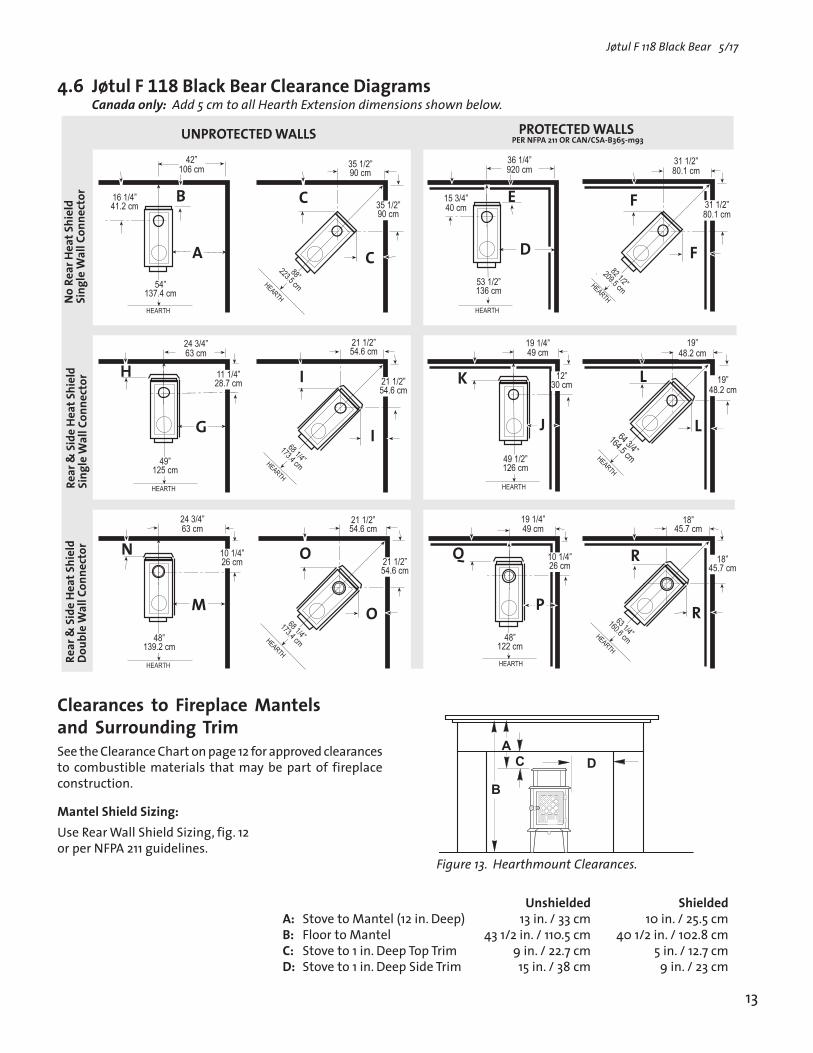
Unshielded ShieldedA: Stove to Mantel (12 in. Deep) 13 in. / 33 cm 10 in. / 25.5 cm B: Floor to Mantel 43 1/2 in. / 110.5 cm 40 1/2 in. / 102.8 cm C: Stove to 1 in. Deep Top Trim 9 in. / 22.7 cm 5 in. / 12.7 cmD: Stove to 1 in. Deep Side Trim 15 in. / 38 cm 9 in. / 23 cm
Clearances to Fireplace Mantels and Surrounding TrimSee the Clearance Chart on page 12 for approved clearances to combustible materials that may be part of fireplace construction.
Mantel Shield Sizing: Use Rear Wall Shield Sizing, fig. 12 or per NFPA 211 guidelines.
Canada only: Add 5 cm to all Hearth Extension dimensions shown below.
�����
����
�����
�����
����
����
�����
����
���
����
������
�����
�����
���
����
����
�����
����
���
����
������
�����
�����
���
��
����
�����
����
���
����������������� ������������������������������������������ ����
���������
��������������
������
����� �����
�
����
��������������
������������
������������
�
�
������������
���������� ���
������
���������
�
�
�������� ������������
��������������
�
�
��������������
������
�
�
��������������
��������������
�������� ������
������
�����������
������������
�
�
������������
������
�������������
������������
���������
��������
��������������
����������
����������
�
�
������ ���
���������������������
������ ���
�
�
������
�������������
�������������
�������������
�
������
���������
������������
�
�
������������
��������������
���������������������
�
�
��������������
��������������������������������� ����� ��� ���������������������� ����� ���� �������������������������� ������ ���� ����� ��������������������� ��������� ���������������������������������������������������������� ���������
���
�
Figure 13. Hearthmount Clearances.
4.6 Jøtul F 118 Black Bear Clearance Diagrams

Jøtul F 118 Black Bear 5/17
14
5.0 OperationPlease read the following section before building the first fire in your new Jøtul F 118 Black Bear.
5.1 Combustion EfficiencyThe Jøtul F 118 Black Bear has an EPA tested High Heating Value (HHV) efficiency rate of 72.94%. There are aspects of efficiency, however, that you should be aware of in order to get the most from your stove.
Operation habits and fuel moisture can have a significant effect on efficiency. Poorly seasoned wood having a higher than optimum moisture content, can reduce the amount of energy transferred to the living area. Much fuel energy is expended to evaporate excess moisture before the wood can burn. Operational aspects, such as not building a robust kindling fire to readily ignite the larger fuel pieces, can result in an inefficient, smoldering fire. Additionally, most modern wood heaters deliver best performance and efficiency at the medium to medium-low burn rates.
The location of the stove can also have a significant effect on heating efficiency, primarily in regards to distribution of the heat. For example, a wood heater centrally located in the residence in an open living area will likely provide better circulation of heat than will a stove located in a room adjacent to the larger living area.
5.2 Minimize Carbon Monoxide EmissionsTesting the F 118 to CSA B414.1-10 resulted in a carbon monoxide emission rate of 125.32 grams per hour. Most means of combustion produce CO, including wood fires. Maintaining a well-established fire and avoiding operation that produces a smoldering, smoky fire, will greatly reduce CO levels. .
We highly recommended that a CO monitor (detector) be installed in the same room as the stove. The monitor, however, should be located as far away as possible from the stove to avoid alert soundings when adding fuel to the fire.
5.3 Wood Fuel and Stove PerformanceThe F 118 Black Bear is designed to burn natural wood only. Higher efficiencies and lower emissions generally result when burning air-dried, seasoned hardwoods, as opposed to softwoods, green or freshly cut hardwoods. Wood that has been air-dried for a period of 6 to 14 months will provide the cleanest, most efficient heat. Wood seasoned more than 2 years will burn too quickly to take advantage of the stove’s low end efficiency strength.
A seasoned log will have check marks (cracks) on the ends and be lighter than an unseasoned log which will show little or no check marks.
We recommend using a digial moisture meter to determine the moisture content of your wood. For purposes of home heating, your fuel should have a moisture content between 12 - 20%. Wood with higher moisture content will burn, however, very inefficiently. Most of its heat value will be lost to driving water out of the wood. Worse, that moisture will condense as creosote in the relatively cool chimney flue, increasing the potential for a chimney fire. Use of unseasoned or wet wood defeats the purpose of any modern wood-burning stove.
DO NOT BURN:• Coal;• Garbage;• Synthetic fuel or logs;• Material containg rubber, including tires;• Material containing plastics;• Waste petroleum products, asphalt products, paints, paint thinners or solvents;• Materials containing asbestos;• Construction or demolitioin debris;• Railroad ties or pressure-treated wood;• Manure or animal remains;• Salt water driftwood or other previously salt-water; saturated materials; • Unseasoned wood; or• Paper products, cardboard, plywood, or particle board. (The prohibition against burning these materials does not prohibit the use of fire starters made from paper, cardboard, saw dust, wax or similar substances for the purpose of starting a fire.)The burning of any of these materials can result in the release of toxic fumes, or render the heater ineffective and cause smoke. Never use gasoline, gasoline-type lantern fuel, kerosene, charcoal lighter fluid, or similar liquids to start or “freshen-up” the fire. Always keep such liquids away from
WARNINGALWAYS WEAR STOVE GLOVES WHILE TENDING THE FIRE.NEVER ALLOW THE FIRE TO REST DIRECTLY ON THE GLASS. KEEP THE LOGS SPACED AT LEAST ONE INCH FROM THE GLASS TO ALLOW FOR PROPER AIR FLOW WITHIN THE STOVE. AVOID STRIKING THE GLASS WITH LOGS.
OPERATE THIS STOVE ONLY WITH THE DOOR FULLY CLOSED. OPERATION WITH THE DOOR PARTIALLY OPEN MAY RESULT IN OVER-FIRING. IF THE DOOR IS LEFT PARTIALLY OPEN, GAS AND FLAME MAY BE DRAWN OUT OF THE STOVE CREATING SAFETY RISKS FROM BOTH FIRE AND SMOKE.

15
Jøtul F 118 Black Bear 5/17
�����
������
5.4 How Your Stove WorksThe modern version of the original Jøtul F 118 builds on the strengths of its predecessor; a long, front-to-back burn pattern combines with a baffled heat exchange chamber to promote maximum heat transfer. Your new Jøtul F 118 Black Bear, however, burns fuel substantially more efficiently. The CrossFlow combustion system directs a precise volume of pre-heated secondary air through stainless steel tubes located along the sides, directly under the baffle at the top of the burn chamber. Volatile gases, released unburned from the fuel bed, rise to the baffle where they are turbulently mixed with the fresh oxygen. Secondary combustion then occurs before the gases pass into the heat exchange chamber. See fig. 14.
5.5 Primary Air ControlLocated in the Load Door, this shutter regulates and directs primary air to the front of the burn chamber. Fig. 15, A. Push it to the right to allow maximum air to support combustion. It should be fully open when first starting or rekindling a fire, or when greater heat output is desired.
Clean Glass / Air Wash A fixed amount of primary air also enters the firebox directly above the glass panel on the door. This incoming air creates a turbulent barrier or ”airwash” between the glass and the fire which helps keep the glass clean.
Figure 15. Air Shutter Control
Figure 14. Combustion air paths
ExhaustSecondary AirPrimary Air
Jøtul F 118 Black Bear 5/17
16
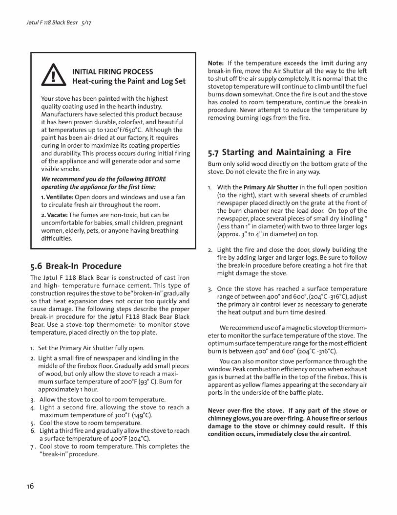
INITIAL FIRING PROCESSHeat-curing the Paint and Log Set
Your stove has been painted with the highest quality coating used in the hearth industry. Manufacturers have selected this product because it has been proven durable, colorfast, and beautiful at temperatures up to 1200°F/650°C. Although the paint has been air-dried at our factory, it requires curing in order to maximize its coating properties and durability. This process occurs during initial firing of the appliance and will generate odor and some visible smoke.We recommend you do the following BEFORE operating the appliance for the first time:1. Ventilate: Open doors and windows and use a fan to circulate fresh air throughout the room. 2. Vacate: The fumes are non-toxic, but can be uncomfortable for babies, small children, pregnant women, elderly, pets, or anyone having breathing difficulties.
�
5.6 Break-In ProcedureThe Jøtul F 118 Black Bear is constructed of cast iron and high- temperature furnace cement. This type of construction requires the stove to be“broken-in” gradually so that heat expansion does not occur too quickly and cause damage. The following steps describe the proper break-in procedure for the Jøtul F118 Black Bear Black Bear. Use a stove-top thermometer to monitor stove temperature, placed directly on the top plate.
1. Set the Primary Air Shutter fully open.2. Light a small fire of newspaper and kindling in the
middle of the firebox floor. Gradually add small pieces of wood, but only allow the stove to reach a maxi-mum surface temperature of 200°F (93° C). Burn for approximately 1 hour.
3. Allow the stove to cool to room temperature.4. Light a second fire, allowing the stove to reach a
maximum temperature of 300°F (149°C).5. Cool the stove to room temperature.6. Light a third fire and gradually allow the stove to reach
a surface temperature of 400°F (204°C).7 . Cool stove to room temperature. This completes the
“break-in” procedure.
Note: If the temperature exceeds the limit during any break-in fire, move the Air Shutter all the way to the left to shut off the air supply completely. It is normal that the stovetop temperature will continue to climb until the fuel burns down somewhat. Once the fire is out and the stove has cooled to room temperature, continue the break-in procedure. Never attempt to reduce the temperature by removing burning logs from the fire.
5.7 Starting and Maintaining a FireBurn only solid wood directly on the bottom grate of the stove. Do not elevate the fire in any way.
1. With the Primary Air Shutter in the full open position (to the right), start with several sheets of crumbled newspaper placed directly on the grate at the front of the burn chamber near the load door. On top of the newspaper, place several pieces of small dry kindling * (less than 1” in diameter) with two to three larger logs (approx. 3” to 4” in diameter) on top.
2. Light the fire and close the door, slowly building the fire by adding larger and larger logs. Be sure to follow the break-in procedure before creating a hot fire that might damage the stove.
3. Once the stove has reached a surface temperature range of between 400° and 600°, (204°C -316°C), adjust the primary air control lever as necessary to generate the heat output and burn time desired.
We recommend use of a magnetic stovetop thermom-eter to monitor the surface temperature of the stove. The optimum surface temperature range for the most efficient burn is between 400° and 600° (204°C -316°C).
You can also monitor stove performance through the window. Peak combustion efficiency occurs when exhaust gas is burned at the baffle in the top of the firebox. This is apparent as yellow flames appearing at the secondary air ports in the underside of the baffle plate.
Never over-fire the stove. If any part of the stove or chimney glows, you are over-firing. A house fire or serious damage to the stove or chimney could result. If this condition occurs, immediately close the air control.

17
Jøtul F 118 Black Bear 5/17
5.8 Adding FuelWhen reloading the stove while it is still hot and a bed of hot embers still exist, follow this reloading procedure:• Always wear gloves when tending to the stove.• Open the Primary Air Shutter and wait a few seconds
before opening the load door. This will allow fresh air to flush the firebox and prevent smoke escaping when the door is opened..
• Use a stove tool or poker to distribute the hot embers equally around the firebox.
• Load the fuel, usually with smaller logs first.• Close the door, be sure to latch the door tightly.• Wait 5 – 10 minutes before setting the air controls
for the desired heat output and burn time. (If you have at least a 2” thick ember bed when reloading, it may be possible to close the door and immediately adjust the air control setting).
• Set the Air Sutter on the door for the desired heat output.
5.9 Open Door Fire-viewingWarning: This stove should be operated with the door either fully open with optional Spark Screen in place or with the door fully closed. If the door is left partly open, there is risk of overfiring. Also, gas and flame may be drawn out of the fireplace stove opening, creating risks from both fire and smoke.
Be aware that when operating with the door open, there exists the possibility of generating carbon monoxide by some fuels (e.g. charcoal), and the hazards of carbon monoxide. Be sure adequate fresh air and ventilation is available to the stove.
5.10 Creosote Formation and the Need for RemovalWhen wood is burned slowly, it produces tar and other vapors that combine with moisture to form creosote. Creosote vapors condense in the relatively cool chimney flue, and creosote residue accumulates on the flue lining. When ignited, this creosote fuels an extremely hot fire.
The chimney connector and chimney flue should be inspected at least twice monthly during the heating season to determine if creosote buildup has occurred.If creosote has accumulated, it should be removed to reduce the chance of a chimney fire.
In the event that creosote ignites in the flue, the resulting fire is often accompanied by a roaring noise and crackling sound as flakes of burning creosote break loose. If you suspect you are having a chimney fire, immediately close the air controls and make sure the door is closed securely. Call the fire department and have everyone leave the house.
Do not attempt to extinguish the fire. Opening the door will only supply additional oxygen and intensify the fire. When the fire in the flue has subsided, resist the temptation to open the door to check on the fire. The fire may have suffocated, but could re-ignite with a supply of fresh air. After a chimney fire, do not use the stove until the chimney connector and flue have been cleaned and inspected to ensure no damage has been sustained.
See Section 6.6 of this manual regarding chimney cleaning.
5.11 Ash RemovalAsh removal will be required periodically, depending on how frequently the stove is used. Avoid letting the ash accumulate to spill over the front lip. For your protection, always wear safety gloves when handling the ashes. Use an ash shovel to remove the accumulation from the bottom of the firebox. It is a good idea to leave a bed of ash in the stove bottom to promote longer burn times and easy start-up.
Ashes should only be placed in a metal container equipped with a tight sealing lid. The container should be placed on a noncombustible floor or on the ground, well away from all combustible materials, pending final disposal. If the ashes are disposed of by burial in soil or otherwise locally dispersed, they should be kept in the closed container until all cinders have thoroughly cooled.

Jøtul F 118 Black Bear 5/17
18
6.2 Glass Removal or Replacement See fig. 16.1. Place the door face down on a protected surface.2. Remove the two screws from the Air Wash Manifold
and remove the manifold.3. Remove the two screws from the Lower Air Manifold
and remove the manifold with gasket.4. Lift the glass panel out of the door.5. Replace the parts in the same order in which they were
removed.
6.3 General CareLike your car, regular maintenance prolongs the life of your stove. The following procedures do not take long and are generally inexpensive, but when done consistently, increase the life of your stove and in turn, increase your years of enjoyment.
Bi-annual Inspection• Empty stove of all soot and ashes. Only use a vacuum for
this job if the vacuum is specifically designed for ashes.• Inspect the stove: Using a strong light inspect the stove
inside and out for cracks or leaks. Replace all cracked parts and repair any cement leaks with furnace cement.
6.4 GasketsCheck door and glass panel gaskets for tightness. To check the seal of the front door, close and latch the door on a dollar bill and slowly try to pull the dollar bill free. You should feel resistance as you pull. If it can be easily removed, the seal is too loose. Check several spots around the door.
Figure 16. Glass and Gasket Replacement
Door Gasket
Glass Panel
Lower Air Manifold
Air Shutter
Air Wash Manifold Glass
Gasket
Air Manifold Gasket
6.0 Maintenance
6.1 Glass Care
CleaningOn occasion it will be necessary to clean the carbon deposits and fly ash off of the glass. If the carbon and fly ash are allowed to remain on the glass for an extended period of time it could eventually cause the glass to become etched and cloudy. Any creosote that might develop on the glass will burn off during the next hot fire.
Follow this glass cleaning procedure:
1. Glass must be completely cool.2. Only use a cleaner that is specifically designed for this
purpose. The use of abrasives will damage the glass and ultimately leave the glass frosted.
3. Rinse and dry glass completely before burning the stove.
Caution! Always operate the door slowly and carefully to avoid cracking or breaking the glass. Never use the door to push wood into the firebox. If the glass becomes cracked or broken follow the replacement procedure below. Never operate the stove with a cracked or broken glass panel.
Important: Replace glass only with ceramic glass panel PN 128101 specifically designed for the Jøtul F 118 Black Bear. Do not use substitutes. Replacement glass is available from your local Jøtul dealer.

19
Jøtul F 118 Black Bear 5/17
6.5 Gasket Replacement1. Use pliers and a putty knife to remove the old gasket
from the door. 2. Thoroughly clean the channel with a wire brush. 3. Apply a small bead of cement to the channel. 4. Gently press the new gasket into the cement to seat
it in the channel. Close and latch the door and then reopen. Wipe away any excess cement that may have squeezed out from around the gasket.
Gasket List for the Jøtul F 118 Black BearDescription Size Length Top Plate Gasket 3/8” LD 7 ft Flue Collar Gasket LD/SA 3 ft Glass Gasket LD 187-1 4.8 x 600 m Door Gasket LD 360 mm 8.7 x 850 mm Air Manifold Gasket LD V-125 8 x 150 mm
Door and Glass Gasket Kit #157050
6.6 Chimney SystemThe Jøtul F 118 Black Bear is designed to burn cleanly and efficiently when used according to the guidelines in this manual. In order to maintain proper performance, you should inspect the chimney and chimney connector at the beginning of each heating season and then every other month during the heating season. Clean the chimney whenever creosote and fly ash accumulation exceeds 1/4 inch in any part of the system.
Chimney brushes are available from your local Jøtul dealer or hardware supply store. Your dealer can also refer you to a reputable, professional chimney sweep who will have all the equipment to ensure a complete and proper job. Failure to keep the chimney system free of creosote and build up could result in a serious chimney fire.

7.0 Illustrated Parts Breakdown
Figure 19.
Jøtul F 118 Black Bear 5/17
20
1 2 3 4 5 6
78
13
910
11
13 14 2 1512 16
17 18
19
20
17
1823
2425
26 27 29 3020
31
32 3334
35 36 20 37 3839
4041
4243
4445
46
4748
32502
5152
538
7
6
2
1
57
17
202
6162636465
66672
6869
2
70
20
3
71
59

21
Jøtul F 118 Black Bear 5/17
Only use replacement parts provided through your authorized Jøtul dealer.
No. Description Part Number1. Smoke Outlet Cover - MB 104448922. Screw, M6 x 16, Hexagon Cap Flange 996253. Gasket, Smoke Outlet 2215184. Rear Plate, Outer 104437925. Screw, M6x40, Hex Cap Flange 1175636. Side Plate, Upper - MB 104445927. Side Plate, Lower - MB 104434928. Burn Plate, Left / Right 104436129. Rear Plate, Lower Inner, MB 1044339210. Refractory Brick, 230 x 55 x 32mm 22149411. Refractory Brick, 230 x 115 x 32mm 12908212. Brick Retainer 1044411213. Bottom Plate, Complete - MB 1044319214. Secondary Air Plate 22583015. Bottom Heat Shield 22149116. Leg - MB 1008179217. Washer, Ø6.4xØ18x1.6 1200418. Screw, M6 x 25 St 8.8 Blk 11801919. Screw, M6 x 12 St 8.8 Blk 11713020. Nut, M6 St8.8, Hex Flange 11796823. Gasket, Secondary Air Tubes, LD 187-1 Ø4,8x150mm 22150324. Secondary Air Tube, Left 22152225. Secondary Air Tube, Front 22151526. Secondary Air Tube, Right 22152127. Front Plate, Upper - MB 1044439229. Front Plate, Lower - MB 1044321230. Glass Panel 12810131. Door Air Valve Housing 1044381232. Screw, M6 x 12mm, Pan Hd 11804233. Air Valve Gasket, V125 8x150mm 12721534. Air Valve Spring 12842735. Air Valve - MB 1031559236. Glass Gasket, LD 187-1 Ø4,8x600mm 20002837. Nut, M8 St8.8, Hex Cap Flange 11699438. Door Latch - MB 1010859239. Insulating Washer, ø22xø8,2x2mm 12485340. Screw, M8x25 St 8.8 DIN 7991 11696041. Door Knob, Wooden - Blk 12992942. Sleeve, Ø8xØ6x62 12993043. Washer, Ø6.4xØ18x1.6 St8.8 Black 12710544. Screw, Cylh Slotted 11782545. Door Gasket, LD 360 Ø8,7x850mm 10003846. Door - MB 15622647. Hinge Pin, Ø6x33 Black chromate 127075 48. Air Deflector - MB 1031529250. Door Catch 12001351. Left Baffle 1046621252. Right Baffle 10466112 Replacement Baffle Kit, inc. #51, #52 15775953. Insulation Blanket 22150657. Screw, M6 x 60 Hex 9910159. Gasket, Top / Upper - LD 375-2 Ø9,5x1657mm 22569561. Washer, Cast Iron 10325312
Jøtul F 118 Black Bear Part List
No. Description Part Number 62. Screw, M6 x 25, Hex Cap Flange 11709963. Traverse Bar 1002291264. Griddle Plate 1044491865. Smoke Outlet - MB 1044479266. Cover Plate 22583167. Top Plate, Lower - MB 1044359268. Top Plate Bracket 1037131269. Top Plate, Upper - MB 15622970. Rear Plate, Upper - MB 1044449271. Socket Set Screw, M6 x 25 117577
MB indicates Matte Black Paint

8.0 Jøtul North America, Inc. Woodburning Product Limited Warranty
This warranty policy applies to wood-burning products identified by Jøtul trade names, as set forth below.
A. LIMITED LIFETIME WARRANTY, parts only:Jøtul North America Inc. (JØTUL) warrants, to the original retail purchaser, that those baffle and air manifold components of the Jøtul or Scan Stove or Fireplace Insert specified above will be free of defects in material and workmanship for the life of the product. This warranty is subject to the terms, exclusions and limitations set forth below.
B. LIMITED FIVE YEAR WARRANTY - Cast Iron and Steel Components:JØTUL warrants, to the original retail purchaser, that those components of the Jøtul or Scan Stove or Fireplace Insert specified above will be free of defects in material and workmanship for a period of five (5) years from the date of purchase. This warranty is subject to the terms, exclusions and limitations set forth below.
C. LIMITED TWO YEAR WARRANTY - Enamel Finish: JØTUL warrants, to the original retail purchaser, the enamel finish on cast iron components of the Jøtul Stove or Fireplace Insert specified above against peeling or fading for a period of two (2) years from the date of purchase. This warranty is subject to the terms, exclusions and limitations set forth below.
D. LIMITED ONE YEAR WARRANTY - Electrical Components (blowers, thermostatic switches): JØTUL warrants, to the original retail purchaser, that those components of the Jøtul or Scan Stove or Fireplace Insert specified above will be free of defects in material and workmanship for a period of one (1) year from the date of purchase. This warranty is subject to the terms, exclusions, and limitations set forth below:
JØTUL will repair or replace at its option, any of the above components determined by JØTUL to be covered by this warranty. You must, at your own expense, arrange to deliver or ship the component to an authorized Jøtul dealer and arrange for pickup or delivery of the component after repairs have been made. If, upon inspection, JØTUL determines that the component is covered by this warranty, the repair or replacement will be made as set forth above. This warranty is not transferable and is extended only to, and is solely for the benefit of, the original retail purchaser of the Jøtul Stove or Fireplace Insert. This paragraph sets forth the sole remedy available under this warranty in the event of any defect in the Jøtul Stove or Fireplace Insert.The warranty period for any replaced component will be the remaining unex-pired portion of the warranty period for the original component.Please retain your dated sales receipt in your records as proof of purchase.
EXCLUSIONS AND LIMITATIONSNOTICE: This warranty is void if installation or service is performed by someone other than an authorized installer or service agency, or if installation is not in conformance with the installation and operating instructions contained in this owners manual or local and/or national fire and building regulations. A listing of local authorized installers, service agencies and gas suppliers can be obtained from the National Fireplace Institute at http://www.nficertified.org/. This warranty does not cover the following:1) Repair or replacement of parts that are subject to normal wear and tear
during the warranty period or to parts that may require replacement in connection with normal maintenance. These parts include paint, gaskets, burn plates, firebricks, fire grates, ceramic insulation blankets or glass (glass is only warranted against thermal breakage).
2) Damage due to incorrect installations not in conformance with the installation instructions contained in this owners manual or local and/or national fire and building regulations.
3) Damage, including damage to enamel surfaces, caused by improper opera-tion, over-firing, and/or misuse. Improper operation, such as burning the stove with the ash door open, can damage the stove. Over-firing occurs when any part of the stove glows red. Over-firing can also be identified by warped plates, rust-colored cast iron, paint pigment that has turned dusty white, or bubbling, cracking and discoloration of the enamel finish. Misuse includes, without limitation, use that is not in conformance with the operating instructions contained in this owners manual.
4) Damage due to, or repair of, rust. Use of stove-top steamers may cause rust.
5) Damage due to service performed by an installer or service agency, unless otherwise agreed to in writing by JØTUL.
6) Damage caused by unauthorized modification, use or repair.7) Costs incurred by travel time and/or loss of service.8) Labor or other costs associated with the repair of components beyond the
warranty period.9) Damage incurred while the Jøtul Stove or Fireplace Insert is in transit.IN NO EVENT SHALL JØTUL, ITS PARENT COMPANY, SHAREHOLDERS, AFFILIATES, OFFICERS, EMPLOYEES, AGENTS OR REPRESENTATIVES BE LIABLE OR RESPONSIBLE TO YOU FOR ANY SPECIAL, INDIRECT, INCIDENTAL, CONSEQUENTIAL, PUNITIVE OR OTHER SIMILAR DAMAGES, INCLUDING, BUT NOT LIMITED TO, LOST PROFITS, LOST SALES, INJURY TO PERSON OR PROPERTY, OR DAMAGES TO A STRUCTURE OR ITS CONTENTS, ARISING UNDER ANY THEORY OF LAW WHATSOEVER. ALL IMPLIED WARRANTIES, INCLUDING THE IMPLIED WARRANTIES OF MERCHANTABILITY AND FITNESS FOR A PARTICULAR PURPOSE, OR OTHERWISE, ARE LIMITED IN DURATION TO THE LENGTH OF THIS WRITTEN WARRANTY. EXCEPT AS EXPRESSLY SET FORTH HEREIN, JØTUL MAKES NO ORAL, WRITTEN OR OTHER WARRANTY WITH RESPECT TO JØTUL OR SCAN STOVES OR FIREPLACES.Some states do not allow the exclusion or limitation of incidental or consequential damages, or limitations on the length of implied warranties. Therefore, the above exclusions or limitations may not apply to you. This warranty gives you specific legal rights, and you may have other rights, which vary from state to state. JØTUL reserves the right to discontinue, modify or change the materials used to produce the Jøtul Stove or Fireplace. JØTUL shall have the right to replace any defective component with substitute components determined by JØTUL to be of substantially equal quality and price. The dollar value of JØTULs liability for breach of this warranty shall be limited exclusively to the cost of furnishing a replacement component. JØTUL shall not in any event be liable for the cost of labor expended by others in connection with any defective component. Any costs or expenses beyond those expressly assumed by JØTUL under the terms of this warranty shall be the sole responsibility of the owner(s) of the Jøtul Stove or Fireplace Insert.
No dealer, distributor, or other person is authorized to modify, augment, or extend this limited warranty on behalf of JØTUL. NO MODIFICATION OR CHANGE TO THIS WARRANTY WILL BE EFFECTIVE UNLESS IT IS MADE IN A WRITTEN DOCUMENT MANUALLY SIGNED BY AN AUTHORIZED OFFICER OF JØTUL.
An authorized installer may have been provided with certain information related particularly to the Jøtul Stove or Fireplace Insert; however, no authorized installer or other person who may service the appliance is an agent of JØTUL. No inference should be made that JØTUL has tested, certified, or otherwise pronounced any person as qualified to install or service the appliance. JØTUL shall not be liable or otherwise responsible for any error or omission by a person installing or servicing a Jøtul Stove or Fireplace Insert.
If you believe your Jøtul or Fireplace Insert is defective, you should contact your nearest authorized Jøtul dealer, who will process a warranty claim. IN ORDER TO QUALIFY FOR WARRANTY COVERAGE, JØTUL MUST RECEIVE NOTICE OF A POSSIBLE DEFECT WITHIN SIXTY (60) DAYS OF THE DATE THE DEFECT IS FIRST DISCOVERED, OR REASONABLY COULD HAVE BEEN DISCOVERED.
T h i s w a r r a n t y i s g i v e n b y J ø t u l N o r t h A m e r i c a , I n c . , 55 Hutcherson Drive, Gorham, Maine 04038 USA
Jøtul F 118 Black Bear 5/17
22

This page is intentionally blank.
23
Jøtul F 118 Black Bear 5/17

Jøtul F 118 Black Bear 5/17
24
139679-R05M
ay 2017
Jøtul AS P.O. Box 1411N-1602 Fredrikstad, Norway
Jøtul North America Inc.P.O. Box 115755 Hutcherson DriveGorham, Maine 04038 USA
www.jotul.us
QualityJøtul pursues a policy of continuous product development. Products supplied may therefore differ in specification, colour and type of accessories from those illustrated and described in the brochures.
We appreciate your trust in welcoming our product into your home and invite your comment and appraisal of our efforts to provide you with the finest in home hearth products.