Jet A Explosions - Field Test Plan 1/4-Scale ExperimentsJet A Explosions - Field Test Plan 1/4-Scale...
65
Jet A Explosions - Field Test Plan 1/4-Scale Experiments J. E. Shepherd, J. C. Krok and J. J. Lee Explosion Dynamics Laboratory California Institute of Technology Pasadena, CA 91125 M. M. Birky National Transportation Safety Board 490 L’Enfant Plaza, SW Washington DC 20594 June 27, 1997 Revised December 6, 1997 Explosion Dynamics Laboratory Report FM97-17 Prepared for and supported by the National Transportation Safety Board Under Order NTSB12-97-SP-0127
Transcript of Jet A Explosions - Field Test Plan 1/4-Scale ExperimentsJet A Explosions - Field Test Plan 1/4-Scale...
Jet A Explosions - Field Test Plan
1/4-Scale Experiments
J. E. Shepherd, J. C. Krok and J. J. LeeExplosion Dynamics LaboratoryCalifornia Institute of Technology
Pasadena, CA 91125
M. M. BirkyNational Transportation Safety Board
490 L’Enfant Plaza, SWWashington DC 20594
June 27, 1997
Revised December 6, 1997
Explosion Dynamics Laboratory Report FM97-17
Prepared for and supported by the National Transportation Safety BoardUnder Order NTSB12-97-SP-0127
Contents
1 Introduction 1
2 Issues 2
3 Testing Program 43.1 Tank Model . . . . . . . . . . . . . . . . . . . . . . . . . . . . . . . . . . 43.2 Test Matrix . . . . . . . . . . . . . . . . . . . . . . . . . . . . . . . . . . 5
4 Fuel-air mixture 9
5 Scaling issues 115.1 Geometrical scaling . . . . . . . . . . . . . . . . . . . . . . . . . . . . . . 115.2 Fuel Amount Considerations . . . . . . . . . . . . . . . . . . . . . . . . . 125.3 Passageways and Vents . . . . . . . . . . . . . . . . . . . . . . . . . . . . 15
5.3.1 Passageways . . . . . . . . . . . . . . . . . . . . . . . . . . . . . . 155.3.2 Vent Stringers . . . . . . . . . . . . . . . . . . . . . . . . . . . . . 15
5.4 Quenching . . . . . . . . . . . . . . . . . . . . . . . . . . . . . . . . . . . 165.5 Structural . . . . . . . . . . . . . . . . . . . . . . . . . . . . . . . . . . . 16
5.5.1 Failure . . . . . . . . . . . . . . . . . . . . . . . . . . . . . . . . . 165.5.2 Motion . . . . . . . . . . . . . . . . . . . . . . . . . . . . . . . . . 18
6 Diagnostic measurements 196.1 Pressure . . . . . . . . . . . . . . . . . . . . . . . . . . . . . . . . . . . . 196.2 Temperature . . . . . . . . . . . . . . . . . . . . . . . . . . . . . . . . . . 216.3 Flame Speed . . . . . . . . . . . . . . . . . . . . . . . . . . . . . . . . . . 216.4 Partition motion . . . . . . . . . . . . . . . . . . . . . . . . . . . . . . . 216.5 Visualization . . . . . . . . . . . . . . . . . . . . . . . . . . . . . . . . . 216.6 Data Acquisition . . . . . . . . . . . . . . . . . . . . . . . . . . . . . . . 226.7 Fuel Handling . . . . . . . . . . . . . . . . . . . . . . . . . . . . . . . . . 226.8 Ignition System . . . . . . . . . . . . . . . . . . . . . . . . . . . . . . . . 236.9 Safety Considerations . . . . . . . . . . . . . . . . . . . . . . . . . . . . . 24
7 Caltech, Contractor and NTSB Roles 247.1 Caltech Responsibilities . . . . . . . . . . . . . . . . . . . . . . . . . . . 247.2 Contractor Responsibilities . . . . . . . . . . . . . . . . . . . . . . . . . . 247.3 Reporting . . . . . . . . . . . . . . . . . . . . . . . . . . . . . . . . . . . 257.4 Information Release . . . . . . . . . . . . . . . . . . . . . . . . . . . . . . 25
8 Schedule 25
9 Budget 25
10 Technical Contacts 27
i

A CWT Geometry 29
B 1/4-Scale Facility 45
ii

List of Figures
1 Cut-away view of the 747-100 Center Wing Tank (CWT) showing beamsand spars that partition the tank into compartments. Passageways andexternal vents are not shown. . . . . . . . . . . . . . . . . . . . . . . . . 1
2 Schematic of the 1/4-scale model of the CWT. . . . . . . . . . . . . . . . 53 Side view schematic of the 1/4-scale model of the CWT. . . . . . . . . . 64 Combustion tests in the 1/4-scale model of the center wing tank. a) to c)
Tests with rigid partition connections to top and bottom plates. d) Testswith weak partition connections and variable ignition location. . . . . . . 7
5 Combustion tests using LAX and El Monte Jet A in the Hyjet Facility(1180 liters), mass loading of 3 kg/m3, spark ignition, pressure of 0.585bar (14 kft equivalent). . . . . . . . . . . . . . . . . . . . . . . . . . . . . 10
6 Comparison of combustion tests using LAX Jet A at 50◦C mass loadingof 3 kg/m3 and 0.585 bar, and propane/hydrogen (1.4%/7%) at 25◦C and0.83 bar in the Hyjet Facility (1180 liters), both with spark ignition. . . . 11
7 Plan view of 1/4-scale facility showing the compartment labeling, locationsof partitions, and vents. . . . . . . . . . . . . . . . . . . . . . . . . . . . 13
8 Positioning of the gauges on the top plate of the tank in one compartment. 209 Conceptual design for location of cameras used in visualization of the flame
propagation and partition motion. . . . . . . . . . . . . . . . . . . . . . . 2210 Proposed schedule for 1/4-scale test program. . . . . . . . . . . . . . . . 2611 Schematic of 747-100 showing the location of Center Wing Tank. . . . . . 2912 Perspective views of Center Wing Tank. . . . . . . . . . . . . . . . . . . 3013 Location of the CWT within the fuselage, cross sectional view showing
ACMs. . . . . . . . . . . . . . . . . . . . . . . . . . . . . . . . . . . . . . 3114 Schematic of 747-100 CWT venting arrangement. . . . . . . . . . . . . . 3215 Side view of CWT. Actual dimensions. . . . . . . . . . . . . . . . . . . . 3316 Front spar (FS) of CWT. Actual dimensions. . . . . . . . . . . . . . . . . 3417 Location of water bottles on Front spar (FS) of CWT. Actual dimensions. 3518 Spanwise beam 3 (SWB3) of CWT. Actual dimensions. . . . . . . . . . . 3619 Spanwise beam 2 (SWB2) of CWT. Actual dimensions. . . . . . . . . . . 3720 Midspar (MS) of CWT. Actual dimensions. . . . . . . . . . . . . . . . . . 3821 Spanwise beam 1 (SWB1) of CWT. Actual dimensions. . . . . . . . . . . 3922 Rear spar (RS) of CWT. Actual dimensions. . . . . . . . . . . . . . . . . 4023 Partial rib between RS and SWB1 of CWT. Actual dimensions. . . . . . 4124 Partial rib between SWB1 and MS of CWT. Actual dimensions. . . . . . 4225 Perspective view of assembled 1/4-scale facility. . . . . . . . . . . . . . . 4526 Side view of assembled 1/4-scale facility. . . . . . . . . . . . . . . . . . . 4627 End view of assembled 1/4-scale facility. . . . . . . . . . . . . . . . . . . 4728 Close-up side view of assembled 1/4-scale facility. . . . . . . . . . . . . . 4829 Top plate layout for 1/4-scale facility. . . . . . . . . . . . . . . . . . . . . 4930 Bottom plate layout for 1/4-scale facility. . . . . . . . . . . . . . . . . . . 50
iii

31 Strong partition mounting scheme. 1/4-scale facility. . . . . . . . . . . . 5132 Strong partition mounting holes. 1/4-scale facility. . . . . . . . . . . . . . 5233 SWB1 hole layout for 1/4-scale facility. . . . . . . . . . . . . . . . . . . . 5334 MS hole layout for 1/4-scale facility. . . . . . . . . . . . . . . . . . . . . . 5435 SWB2 hole layout for 1/4-scale facility. . . . . . . . . . . . . . . . . . . . 5536 Forward partial rib hole layout for 1/4-scale facility. . . . . . . . . . . . . 5637 Aft partial rib hole layout for 1/4-scale facility. . . . . . . . . . . . . . . . 5738 Window hole layout for 1/4-scale facility. . . . . . . . . . . . . . . . . . . 5839 Window sealing detail for 1/4-scale facility. . . . . . . . . . . . . . . . . . 5840 Plumbing detail for 1/4-scale facility. . . . . . . . . . . . . . . . . . . . . 59
iv

List of Tables
1 Factorial representation of test parameters . . . . . . . . . . . . . . . . . 72 Proposed Tests . . . . . . . . . . . . . . . . . . . . . . . . . . . . . . . . 83 Volume scaling and partition locations. . . . . . . . . . . . . . . . . . . . 124 Fuel-air mass ratios, equivalence ratios, and adiabatic combustion pressure
(.83 atm, 23◦C) for propane/hydrogen blend in air combustion. . . . . . . 145 Effect of initial temperature on AICC pressure at an initial pressure of .83
atm for the nominal propane/hydrogen blend in air combustion. . . . . . 146 Actual and scaled areas between compartments of the center wing tank
and 1/4-scale model. . . . . . . . . . . . . . . . . . . . . . . . . . . . . . 167 Estimate pressure differentials required to fail spanwise beams and spars
in the CWT. Information provided by Boeing in briefing of Feb. 6, 1997. 178 Failure pressure differentials of maintenance and manufacturing doors. In-
formation provided by Boeing in letter of May 30, 1997. . . . . . . . . . . 189 Actual or estimated panel mass and scaled value for 1/4-scale facility . . 1910 Summary of diagnostic instrumentation . . . . . . . . . . . . . . . . . . . 2311 Passageways in Spanwise Beam 1 (SWB1). . . . . . . . . . . . . . . . . . 4312 Passageways in the Midspar (MS). . . . . . . . . . . . . . . . . . . . . . 4313 Passageways in Spanwise Beam 2 (SWB2). . . . . . . . . . . . . . . . . . 4314 Passageways in the partial rib between the Rear-spar (RS) and the Mid-
spar (MS). . . . . . . . . . . . . . . . . . . . . . . . . . . . . . . . . . . . 44
v

1 Introduction
The TWA 800 crash investigation is focusing on the explosion of Jet A-air mixtures inthe ullage of the center-wing tank (CWT), see Fig. 1, as the key event in the accident.Laboratory tests are being carried out on Jet A-air mixtures in the 1.2-m3 HYJET facilityat Caltech (Shepherd et al. 1997), and preparations are being made for larger-scale fieldtesting. This document is a proposal for the first phase of the field testing.
PartialRib
78 in.
255 in.
242 in.
48 in.
Figure 1: Cut-away view of the 747-100 Center Wing Tank (CWT) showing beams andspars that partition the tank into compartments. Passageways and external vents arenot shown.
At the present time, one of the main goals of the investigation into TWA 800 is todetermine the location and source of ignition in the CWT. The experimental test pro-gram has been designed to develop basic information that will aid the investigators inreaching this goal. Laboratory experiments have so far examined issues relating to fuelchemical properties, flammability limits and pressure histories during controlled labora-tory explosions of Jet A vapor and air. Laboratory testing to determine ignition energiesand flame speeds is in progress.
All the laboratory testing has been carried out in simple test facilities consisting of asingle, unvented chamber that is relatively small compared to the CWT, which has anapproximate volume (not including the dry bay) of 50 m3. Field testing is needed toaddress the effect of size, compartmentalization, and other factors such as vents in thecenter wing tank. The CWT is divided into six wet bays and one dry bay, see Fig. 1.There are passageways between the bays and vents to the outside of the airplane in fourof the bays. The sequence analysis of the CWT failure indicates that the front spar (FS),the spanwise beam 3 (SWB3) and the manufacturing panel in spanwise beam 2 (SWB2)all failed and were ejected from the airplane early in the event.
The construction of the tank and accident sequence analysis indicate that it is im-portant to understand the phenomena associated with flame propagation in a multicom-
1

partment, vented tank and to also consider the coupling between the flame propagationand structural failure. A program of field tests has been developed to examine theseissues. The experimental testing will proceed in conjunction with numerical simulationswhile maintaining constant feedback between the two programs in order to optimize theexperimental conditions and minimize the number of tests to be conducted.
The field testing has been divided into three phases.
1. 1/4-scale tests in a CWT-like geometry.
2. Full-scale tests of actual CWT or mockups.
3. Full-scale tests using actual aircraft.
The general objective of the Phase 1 tests is to obtain information about combustionin a multicompartment, vented enclosure geometrically similar to the CWT. Phase 2full-scale tests will be carried out to examine the effects of scale and more realisticstructural failure on combustion . The airplane tests in phase 3 are intended to simulateas realistically as possible an explosion of a Jet A-air mixture within the ullage of theCWT in a 747-100 with a pressurized fuselage.
This document focuses exclusively on the 1/4-scale tests. Subsequent documents willdescribe the test program in Phases 2 and 3. The program is proceeding sequentially,with information developed in the earlier phases being used to define the test programin subsequent phases.
2 Issues
We believe that the following issues are significant in determining the combustion phe-nomena in the CWT:
1. Amount of fuel vapor
One of the uncertainties is the amount of fuel present in the vapor form within theullage. The reason for this uncertainty is due to the spatial variation in temperaturewithin the tank and the lack of measurements appropriate to this specific situation.Fuel vapor mass effects have been examined extensively in the laboratory tests andat least two levels of fuel vapor concentration will be compared in the proposed1/4-scale (Phase 1) tests.
2. Ignition location
The primary objective of the investigation is to determine the location and sourceof ignition in the CWT. This will be examined in the Phase 1 tests by carryingout tests with ignition sources in each compartment of the tank as shown in Fig. 4.The pattern of flame propagation, failure of partitions between compartments, andresulting depressurization may give an indication as to the possible ignition loca-tions that could produce the observed CWT failure sequence in TWA-800. Onekey objective of these tests will be to determine if that is possible in a scale model.
2
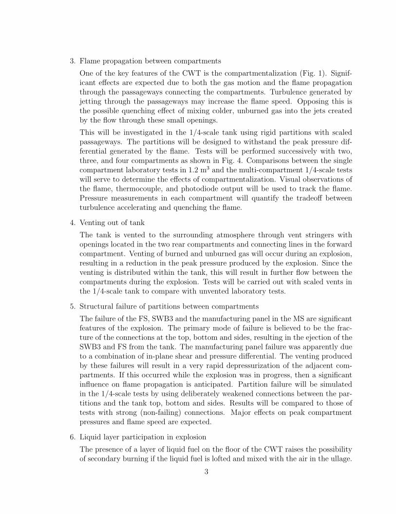
3. Flame propagation between compartments
One of the key features of the CWT is the compartmentalization (Fig. 1). Signif-icant effects are expected due to both the gas motion and the flame propagationthrough the passageways connecting the compartments. Turbulence generated byjetting through the passageways may increase the flame speed. Opposing this isthe possible quenching effect of mixing colder, unburned gas into the jets createdby the flow through these small openings.
This will be investigated in the 1/4-scale tank using rigid partitions with scaledpassageways. The partitions will be designed to withstand the peak pressure dif-ferential generated by the flame. Tests will be performed successively with two,three, and four compartments as shown in Fig. 4. Comparisons between the singlecompartment laboratory tests in 1.2 m3 and the multi-compartment 1/4-scale testswill serve to determine the effects of compartmentalization. Visual observations ofthe flame, thermocouple, and photodiode output will be used to track the flame.Pressure measurements in each compartment will quantify the tradeoff betweenturbulence accelerating and quenching the flame.
4. Venting out of tank
The tank is vented to the surrounding atmosphere through vent stringers withopenings located in the two rear compartments and connecting lines in the forwardcompartment. Venting of burned and unburned gas will occur during an explosion,resulting in a reduction in the peak pressure produced by the explosion. Since theventing is distributed within the tank, this will result in further flow between thecompartments during the explosion. Tests will be carried out with scaled vents inthe 1/4-scale tank to compare with unvented laboratory tests.
5. Structural failure of partitions between compartments
The failure of the FS, SWB3 and the manufacturing panel in the MS are significantfeatures of the explosion. The primary mode of failure is believed to be the frac-ture of the connections at the top, bottom and sides, resulting in the ejection of theSWB3 and FS from the tank. The manufacturing panel failure was apparently dueto a combination of in-plane shear and pressure differential. The venting producedby these failures will result in a very rapid depressurization of the adjacent com-partments. If this occurred while the explosion was in progress, then a significantinfluence on flame propagation is anticipated. Partition failure will be simulatedin the 1/4-scale tests by using deliberately weakened connections between the par-titions and the tank top, bottom and sides. Results will be compared to those oftests with strong (non-failing) connections. Major effects on peak compartmentpressures and flame speed are expected.
6. Liquid layer participation in explosion
The presence of a layer of liquid fuel on the floor of the CWT raises the possibilityof secondary burning if the liquid fuel is lofted and mixed with the air in the ullage.
3

This may be particularly significant during the explosive decompression that oc-curred when the FS and SWB3 failed. A layer of liquid will be placed on the floorof the 1/4-scale tank in selected tests with weak partition connections (Fig. 4d).Visual observations of the flame propagation and measurements of pressure (inter-nal and external to the tank) will indicate the extent and effect of fuel lofting andsecondary burning.
3 Testing Program
We propose a limited campaign of about 26 tests in a 1/4-scale mockup of the center wingtank. The issues we are examining in these tests are discussed below. This campaignis designed to systematically investigate these issues by varying the number of compart-ments, strength of the partitions, location of ignition, amount of fuel vapor and liquid.The tests will proceed in a logical sequence from the simplest configuration to the mostcomplex.
The 1/4-scale tank model will be extremely simplified compared to the actual CWT.Volumes and vent areas will be geometrically scaled (see scaling discussion below), how-ever, there will be very limited scaling of the structure and no attempt to replicatecrack propagation, deformation or other structural failure mechanisms. Initially, onlythe effects of combustion in a rigid tank with various numbers of compartments will beexamined. Later tests will study the effect of the complete failure of the connections ofpartitions corresponding to the FS and SWB3 to the upper and lower skin of the tank.Finally, tests will be carried out with lightweight, weak beams, spars and partial ribs.
3.1 Tank Model
The 1/4-scale tank will essentially consist of a rectangular vessel (Fig. 2) with nonyieldingsteel top, bottom, rear spar, and transparent sides. The tank can be divided by a variablenumber of partitions which can be either be rigidly connected to the top and bottom orelse have weak connections designed to fail at a predetermined pressure difference betweenadjacent compartments or bays. The tank can be divided into seven bays, representingthe six fuel tank “wet” bays and the dry bay. The division is by metal panels thatrepresent the main spars or beams and transparent, high-strength plastic (Lexan) thatrepresents the partial ribs. The partitions representing SWB1, SWB2, MS and the partialribs will have scaled communicating passageways. The front compartment is a dry baywhich is not filled with the fuel-air mixture like the other compartments. The front sparand attached water bottles will be simulated in some tests. The top plate is fitted withdiagnostic gauges and also contains scaled vents to the exterior.
The required amount of fuel will be introduced into the tank using a propane-hydrogengas simulant for the Jet A vapor and cold liquid Jet A in the case of the liquid fuel. Thetank will be sealed and partially evacuated before introducing the gaseous and liquidfuel. The method of partial pressures will be used to meter in the correct amount of fuel
4

Lexanside-windows
partitions
spark igniter
5 ft
5 ft
1.5 ft
inter-connectingvents
opening
diagnosticgauge ports
heavy steelplates
Lexanfront-window
Figure 2: Schematic of the 1/4-scale model of the CWT.
vapor. The liquid Jet A will be at a sufficiently low temperature that its vapor pressurewill make no contribution to the initial fuel-air mixture. The fuel will be distributed toeach compartment by a manifold and subsequently mixed with the air by circulating themixture through the tank with a mixing pump connected to the external vents.
The partitions consist either of thick (0.75-in) or thin (0.090-in) aluminum sheetsfixed to the rigid top and bottom plates. The thick partitions are designed to be fixedboundaries and not to fail or to move during the tests. High strength fasteners will beused to attach the thick partitions securely to the upper and lower plates of the testfixture. The lightweight (thin) partitions are attached at the top and bottom edges withshear pins designed to fail when a critical pressure difference (about 20 psi) is appliedon the partition. Each type of partition contains scaled passageways between the bays.The partitions are interchangeable as shown in Fig. 3 and can be chosen to have weak orrigid connections depending on the requirements of the experiment.
3.2 Test Matrix
We propose to divide the testing in the 1/4-scale tank into three series (see Table 1).
5

rigid frame
rigid top plate
rigid bottom plate
strong or weakpartitions
sparkigniter
flame front
compartments
Figure 3: Side view schematic of the 1/4-scale model of the CWT.
The first series consists of ALPHA tests with an increasing number of rigid partitions,as shown in Figs. 4a through 4c. These start with a single volume and work up tofour subdivisions. The ignition location is fixed and the tank is not vented, althoughcommunication through the vents can occur.
The second series of BETA tests will use rigid partitions to observe the effect ofignition location on flame acceleration process from one compartment to the next. Testswith a single partition will be used to examine the effect of distributed passageways vs.a single hole.
In the third series of GAMMA tests, the effects of partition failure and ignition lo-cation will be investigated. Partitions with weak connections will be used in these testsand the ignition source will be placed in different compartments as shown in Fig 4d. Ineach series, some tests will be carried out with a layer of liquid fuel placed on the tankfloor to investigate the possibility of fuel lofting and secondary combustion. Tests withhigh (H) and low (L) fuel concentrations will be carried out in addition to the standard(S) level.
The DELTA series tests are reserved for repeating tests with anomalies or doing avariation that is decided during the course of the test series.
The summary of all parameter combinations tested are shown in matrix form inTable 1.
The proposed number of tests is 26. We anticipate that the number and sequence oftests will change as the test program proceeds. The results will be assessed on an ongoingbasis to determine if modifications to the test conditions are appropriate. A tentative setof test conditions for each of the 26 tests is proposed in Table 2. This set of conditionsis for planning purposes only.
6

rigid partitionwith vents
igniter rigid partitionwithout vents
strong box
rigid partitionwith vents
igniter partition
without vents
strong box
(a) (b)
rigid partitionwith vents
igniter partition
without vents
strong box
weak partitionswith vents
igniterpositions
weak partitionwithout vents
strong box
liquid fuellayer
(c) (d)
Figure 4: Combustion tests in the 1/4-scale model of the center wing tank. a) to c) Testswith rigid partition connections to top and bottom plates. d) Tests with weak partitionconnections and variable ignition location.
Table 1: Factorial representation of test parameters
Partition connections Strong Strong WeakNumber of compartments 1 2 3 4 6 7Ignition compartment 5 5 3 2 1 5 3 2 1Vapor fuel S S S S S S S S L, S, H S S SLiquid fuel X X X X X
7

Table 2: Proposed Tests
Test Config. Ign. Partitions Vented Fuel CommentsALPHA
A1 All strong 5 none No Standard1 BaselineA2 All strong 5 MS No Standard 2-compartmentA3 All strong 5 MS,SWB2 No Standard 3-compartmentA4 All strong 5 MS, SWB2,
SWB1No Standard 4-compartment
A5 All strong 5 MS with 2-in diamhole
plugged Standard Validation test
BETAB1 All strong 5 All2 Yes Standard Full-upB2 All strong 3 All2 Yes Standard Full-upB3 ll strong 2 All2 Yes Standard Full-upB4 All strong 1 All2 Yes Standard Full-upB5 All strong 5 All2 Yes Standard w/liquid Full-upB6 All strong 6R3 All2 Yes Nominal Ignition locationB7 All strong 1R3 All2 Yes Nominal Ignition location
GAMMAC1 One weak 5 SWB3 weak Yes Standard Model testC2 All strong 5 All strong with
weak access doorin SWB2
Yes Standard Access door fail
C3 2 weak 5 SWB3, FS weak,weak access doorin SWB2
Yes Standard Access door fail
C4 All weak 5 All2 Yes Standard failing partitionsC5 All weak 5 All2 Yes Standard w/liquid loftingC6 All weak 2L3 All2 Yes Standard w/liquid loftingC7 All weak 1 All2 Yes Standard w/liquid loftingC8 All weak 2L3 All2 Yes Low 1 7% total fuelC9 All weak 2L3 All2 Yes Low 2 6% total fuelC10 All weak 2L3 All2 Yes Standard ComparisonC11 All weak 2L3 All2 Yes Standard w/liquid Tilt tank, 6 deg
DELTAD1-D3 TBD TBD TBD TBD TBD RepeatsNotes:
1 Standard mixture is 1.4% C3H8, 7% H2, 91.6% air2 All partitions includes: SWB1, MS, SWB2, and both Partial Ribs3 Ignition location that simulate fuel probes: 1R, far right side next to
SWB2 at top; 6R, far right next to SWB1 at top; 2L, Butt line, 2-infrom bottom (compensator)
8

4 Fuel-air mixture
Since the exact TWA-800 ullage conditions (composition, pressure, temperature) at thetime of the explosion are difficult to reproduce in outdoor testing with vented tanks, avapor fuel simulant will be used instead of Jet A vapor. The mixtures to be used in thetests have been chosen to mimic the properties of Jet A and the environmental conditionsof the explosion at 14 kft in TWA 800 (see the discussion in Shepherd et al. 1997).
Recent flight testing (Bower 1997) indicates that at the time of the explosion, thetemperatures in the air within the CWT ranged between 38 and 54◦C (100 and 130◦F),and the tank lower surface temperatures ranged between 38 and 60◦C (100 and 140◦F).Based on these temperatures and measured vapor pressures at Caltech, the fuel-air com-position within the tank was in the flammable range with fuel-air mass ratios1 between0.040 and 0.072 (mole fractions between .0089 and .015). These estimates are corrobo-rated by the vapor sampling Sagebiel (1997), who measured fuel-air mass ratios between.048 and .054 (mole fractions between 0.010 and 0.012) at 14kft. These values shouldbe compared with a lean limit fuel-air mass ratio of 0.030 (mole fraction of 0.007) and astoichiometric fuel-air mass ratio of 0.070 (mole fraction of 0.015).
The fuel simulant is blend of hydrogen and propane. Jet A will be used for the fuelliquid in the cases where the liquid fuel layer on the tank floor is simulated. The fuelsimulant was chosen on the basis of laboratory testing comparing explosions of Jet Avapor in air at a simulated altitude of 14 kft with propane/hydrogen air mixtures at thepressure altitude of the test site (.83 atm).
Peak pressures for fuel-air mixtures depend primarily on the fuel-air mass ratio (f= Mfuel/Mair). For a vapor fuel this depends purely on the fuel type and the partialpressure of fuel. For a vapor that is produced by and in equilibrium with a liquid, thevapor state is determined by the liquid fuel type, mass loading (mass of fuel per vaporvolume) and the temperature.
If the exact composition of the fuel is known, the pressure can be estimated byperforming a constant volume calculation. However Jet A is a complex blend of severalhundred species, and the actual measured pressures are lower due to heat transfer betweenthe mixture and the confinement walls. Therefore experimental tests must be performedto determine the peak explosion pressure. These tests have been carried out in laboratoryscale experiments for Jet A and for the proposed simulant mixtures.
The results of experiments on Jet A at a mass loading of 3 kg/m3 (appropriate to theTWA 800 CWT conditions) and temperatures between 40 and 60◦C are shown in Fig. 5.As shown, the peak pressure rise varies between 2 and 4 bar for initial temperaturesbetween 40 and 60◦C. From these measurements and the previous considerations aboutthe temperatures and fuel concentrations measured in the flight test, we have selectedthe 50◦C condition as being representative of TWA tank contents at 14 kft. In terms ofJet A vapor concentration, this case has a fuel-air mass ratio of 0.055 and a fuel molefraction of 0.012.
1In making these computations, we have used Sagebiel’s estimated Jet A vapor composition ofC9.58H17.2, which has an average molar mass of 132 g/mole.
9

0
0.5
1
1.5
2
2.5
3
3.5
4
0 0.5 1 1.5 2 2.5 3
pres
sure
ris
e (b
ar)
time (s)
Jet A, 40 CJet A, 40 C
Jet A, 40 C (fan)Jet A, 50 C Jet A, 60 C
Figure 5: Combustion tests using LAX and El Monte Jet A in the Hyjet Facility (1180liters), mass loading of 3 kg/m3, spark ignition, pressure of 0.585 bar (14 kft equivalent).
After a series of experiments, a combination of fuels was found that approximatelysimulated the pressure-time characteristics of Jet A at 50◦C. This combination was testedat a reduced pressure (0.83 bar) to correspond to the higher elevation of the proposedtest site. A comparison between the simulant mixture of 1.4% propane, 7% hydrogenand 91.6% air and Jet A is shown in Fig. 6. Analysis of these pressure traces indicatesthat peak pressure rise is slighty larger for the simulant (∆Pmax = 3.65 bar) than for theJet A (∆Pmax = 3.36 bar). However, the simulant has a slightly lower effective burningvelocity (as determined by the ∆P 1/3 analysis discussed in Shepherd et al. (1997)) of 52cm/s as compared to 60 cm/s for the Jet A. Note that at 40◦C, Jet A has an effectiveburning velocity of 15 to 18 cm/s and at 60◦C, 66 cm/s.
In addition to matching the peak pressure and flame speed, some considerationsabout the scaling of flame propagation are needed. Previous work on scale models ofexplosions (Mercx et al. 1995) indicate that small concentrations of oxygen or hydrogenmay be required in order to increase the laminar burning velocity and prevent quenching.Separate laboratory experiments on quenching were carried out to show that the simulantmixture did not quench when passing through a 0.5-in diameter hole, the smallest sizeused to simulate the passageways through the beams, spar and partial ribs. However,quenching was observed with a 0.25-in diameter hole. These tests were carried out in theHyjet facility, starting the flame in the 27-liter driver vessel which was connected at oneend by the orifice to the 1180-liter main vessel.
10

0
0.5
1
1.5
2
2.5
3
3.5
4
0 0.5 1 1.5 2 2.5 3
pres
sure
ris
e (b
ar)
time (s)
1.4% C3H8, 7% H2Jet A, 50 C
Figure 6: Comparison of combustion tests using LAX Jet A at 50◦C mass loading of3 kg/m3 and 0.585 bar, and propane/hydrogen (1.4%/7%) at 25◦C and 0.83 bar in theHyjet Facility (1180 liters), both with spark ignition.
5 Scaling issues
A basic geometric scaling of the main CWT dimensions is performed. Passagewaysbetween compartments and exterior vents are scaled to achieve similarity in the fluidflow and flame propagation phenomena. The effect of partition motion on the flamepropagation is investigated with a scaled mass partition designed to “fail” (disconnectfrom the top and bottom surfaces of the tank model) at a prescribed pressure difference.Complete similarity of the model is not attempted because that would be overly complexfor the purposes of the present study. For example, we do not propose to include thenumerous stringers and stiffeners that are used in the actual CWT. Nor do we propose tomodel the type of structural failure that was observed. We only propose to model thosefeatures (partitions, vents, passageways between compartments) that are important tothe basic combustion processes that the 1/4-scale tests are intended to address.
5.1 Geometrical scaling
The main geometrical features of the tank will be scaled in proportion to the commonscaling factor α = 1/4. All lengths L will therefore be smaller in the model by thatfactor, areas will be reduced by α2, and volumes by α3.
Lmodel = αL Amodel = α2A Vmodel = α3V (1)
11

The full-scale CWT has a total volume (excluding the dry bay) of 50.1 m3. The1/4-scale model should therefore have a volume of 0.78 m3 and the same proportions asthe actual tank. Our model is a compromise between exact geometric similarity and easeof construction.
As shown in Fig. 1, the actual CWT is rectangular in planform but increases 50% inheight in going from the rear spar to the front spar. For simplicity, we have neglectedthe height variation and approximated the CWT as a rectangular box with a constantheight. The nominal dimensions chosen for the box (60-in wide × 60-in long × 18-inhigh) correspond closely to actual 1/4-scale dimensions (63.75-in wide × 60-in long ×12-in high at the RS, 19.5-in high at the FS). The location of the model SWBs, MS andFS have been chosen to give the exact scaled volumes of the corresponding compartmentsin the CWT. The actual volumes, scaled volumes and locations are given in Table 3. Thenotation is given in the plan view layout, Fig. 7. The locations of the partitions arenominal values that do not account for the partition thickness. Dimensions of the testtank will be adjusted to compensate for the partition thickness.
Table 3: Volume scaling and partition locations.
Compartment V (actual) V (1/4-scale) Location from RS (scale)(m3) (in3) (in)
5 6.25 5956. 11.066 6.25 5956. 11.06
3 5.55 5291. 20.84 5.55 5291. 20.8
2 11.1 14707. 30.6
1 15.4 14707. 44.2
total ullage 50.1 47770. -
0 15.2 14524. 57.75
As a first approximation, vent and passageways will be scaled geometrically but thereare other considerations as discussed below.
5.2 Fuel Amount Considerations
It is estimated that about 50 gal or 150 kg of liquid fuel remained in the bottom of thetank when TWA 800 reached JFK. Determining how much was in the vapor state at thetime of the explosion is a complex problem (Shepherd et al. 1997). The tank would have
12

Figure 7: Plan view of 1/4-scale facility showing the compartment labeling, locations ofpartitions, and vents.
to be filled with appropriate mass of Jet A, differentially heated, and dynamically ventedto a pressure of 0.585 bar (corresponding to 14 kft) in order to simulate the events leadingup to the explosion. Even if this was done, it is not clear that this is the appropriatemethod of handling the fuel in a sub-scale model since heat transfer and quenching donot scale directly with the linear scale factor. Requiring the model tank to accommodatea sub-atmospheric pressure also substantially complicates the design.
This is why we propose to use the propane/hydrogen blend as the main fuel vaporrather than creataing the vapor with warm Jet A in these tests. Jet A will be used asthe liquid fuel, but it will be cool, i.e., at ambient temperature. The liquid fuel amountis proportional to the volume scale factor, which yields 2.34 kg or about 3 l of liquidfor the 1/4-scale model. The vapor fuel amount (8.4% fuel, fuel-air mass ratio of 0.029)was discussed above and is chosen to have a pressure-time history that is close to thenominal Jet A behavior measured in laboratory (Shepherd et al. 1997) experiments.Because hydrogen has very different combustion characteristics than the much heavierhydrocarbons that make up Jet A, it is not possible to directly compare the amount ofsimulant.
Simulant combustion properties for a range of fuel concentrations are given in Table 4.The computed adiabatic, isochoric, complete combustion (AICC) pressures are given fora range of compositions on a warm day. The effect of ambient temperature on the peakpressure is computed for the nominal composition of interest and presented in Table 5.
13

Table 4: Fuel-air mass ratios, equivalence ratios, and adiabatic combustion pressure (.83atm, 23◦C) for propane/hydrogen blend in air combustion.
Fuel fraction Fuel-air Equivalence C3H8 H2 Air O2 N2 PAICC
mass ratio ratio (bar)
1 0.167 0.8330.14 0.051 0.97 0.023 0.117 0.860 0.181 0.679 7.410.13 0.047 0.89 0.022 0.108 0.870 0.183 0.687 7.250.12 0.043 0.81 0.020 0.100 0.880 0.185 0.695 6.860.11 0.039 0.74 0.018 0.092 0.890 0.187 0.703 6.510.1 0.035 0.66 0.017 0.083 0.900 0.189 0.711 6.230.09 0.031 0.59 0.015 0.075 0.910 0.191 0.719 5.790.08 0.027 0.52 0.013 0.067 0.920 0.193 0.727 5.300.07 0.023 0.45 0.012 0.058 0.930 0.195 0.735 4.950.06 0.020 0.38 0.010 0.050 0.940 0.197 0.743 4.41
Standard0.084 0.029 0.55 0.014 0.07 0.916 0.192 0.724 5.6
Table 5: Effect of initial temperature on AICC pressure at an initial pressure of .83 atmfor the nominal propane/hydrogen blend in air combustion.
T PAICC
(◦C) (bar)
-15 6.32-10 6.22-5 6.110 6.015 5.9110 5.8215 5.7220 5.6425 5.5530 5.47
14

5.3 Passageways and Vents
Vented explosion analyses and experiments have identified a simple scaling parameter forventing during combustion:
CdA
V 2/3
Su
co
(ρu
ρb
− 1) (2)
This is for a compartment of volume V vented through an area A with loss coefficientCd, laminar burning velocity Su, initial sound speed co, densities ρu for unburned gas andρb for burned gas. Note that V 2/3 corresponds to the total compartment surface area aslong as the aspect ratio is not large. The thermophysical parameters are all evaluated forthe initial conditions in the tank, i.e., before any compression or venting of the contentshas occurred.
After the gas is burned, there will be venting of the burned gas through the ventstringers and any openings created by failure of the tank pressure boundary, e.g., SBW3and SWB2 access door. This is controlled by the parameter A/V 2/3, again indicatingthat geometric scaling of the vent areas is appropriate.
The vent scaling indicates that if we match the thermophysical properties, i.e., usethe same fuel and initial conditions in the scale model as the actual tank, then the ventarea should be scaled with the geometric-area scaling factor α2. Venting occurs bothbetween compartments (through the passageways) and from the tank to the atmosphere(through the vent stringers). Each case is discussed separately below.
5.3.1 Passageways
The passageways between the compartments will be simulated by drilling or cuttingholes in the partitions in the scaled locations. The size of each hole will be such that thescaled area of the corresponding passageways is reproduced. The details of the actualpenetrations and areas have been provided by Boeing and are attached in the Appendix.The scaled and actual areas between each compartment are given in Table 6.
5.3.2 Vent Stringers
There are two vent stringers. Each stringer is approximately 100 ft long and has a crosssection of 2.75-in by 4.75 (nominal) for a combined area of 26 in2. One stringer (left) isconnected to compartments 3 and 1, the other (right) to 6 and 1. The stringers in therear compartments are connected to the tank through a short length (8-in long) of 2-inOD tube. Compartment 1 is connected to the vent stringers by 3.5-in OD tubes.
The scaled area of both vents combined is 1.68 in2 — not accounting for the flowresistance of the 100-ft long stringer. The venting in the 1/4-scale model will consist of1-in diam openings in the top plate in compartments 5 and 6. These will be connectedthrough tubing to “tees” that connect on one side to 1-in diameter lines connecting to 1-in diameter openings in the top of compartment 1 and on the other side to 1-in diameterlines connected to the atmosphere through a restricting orifice to simulate the 100-ftlength of vent stringer.
15

Table 6: Actual and scaled areas between compartments of the center wing tank and1/4-scale model.
Partition Flow path Actual Flow Area Scaled Flow Area(in2) (in2)
Aft Partial rib 5-6 108.3 6.8Forward Partial rib 2 3-4 44.5 2.8SWB1 (L) 5-3 20.65 1.29SWB1 (R) 6-4 26.2 1.64MS (L) 3-2 25.2 1.58MS (R) 4-2 24.2 1.51SWB2 2-1 34.4 2.15FS 0-FCB 316 19.75
A simple analysis of subsonic and choked flow at the stringer exit indicates that arestriction of 0.45-in diameter would adequately represent the effect of both the flowresistance of the stringer and the flow rate reduction due to choking (high-speed flow).
5.4 Quenching
It has been suggested (Mercx et al. 1995) that it is important to model the possibleeffects of flame quenching in sub-scale gas explosion experiments. Several techniques aresuggested for this and the simplest is to increase the flame speed as follows
Su,model = Su,actualα−1/4 (3)
In the present case, this corresponds to increasing the flame speed by a factor of 1.4. Sincewe are already treating the fuel amount as uncertain and simply varying it as a parametricquantity, factors of 1.4 in the flame speed will not be resolved anyway. It will only beimportant to make sure that the passageways are larger than the quenching diameter forthat mixture. The quenching diameters for the propane/hydrogen-air mixtures has beenmeasured in laboratory experiments at Caltech and is less than 0.5-in. One test will becarried out with a single large diameter (2-in) opening of equal area to the distributedopenings in the MS to examine this issue.
5.5 Structural
5.5.1 Failure
The essential idea is to match the pressure difference between compartments at whichfailure is expected to occur in full scale. Failure pressure differentials for the variousbeams and spars have been estimated by Boeing and are given in Table 7. The first value
16

∆P1 is the pressure differential required for failure if all adjacent panels are intact andthe second value ∆P2 is that needed for failure when an adjacent beam or spar is alreadyfailed. There are access doors in SWB1, MS and SWB2 which are also expected to failwhen the pressure differential reaches about 20 psi. Failure pressures for the variousaccess doors were estimated by Boeing and are given in Table 8.
The accident sequence investigation indicates that FS, SWB3, and the manufacturingaccess panel in SWB2 all completely failed at the earliest stage of the process. SWB2,MS, SWB1, RS and the partial ribs are believed to have remained intact until the aircraftcompletely broke up.
The accident sequence postulated is a progressive failure of first SWB3 (due to thepressure differential resulting from the explosion), the rotation of SWB3 into the FS andsubsequent failure of the FS. The motion of the FS is inhibited by the mass of the twopotable water bottles attached on the Forward Cargo Bay side. The rapid decompressionof the CWT tank resulting from FS and SWB3 failure combined with the in-plane shearloads on SBW2 apparently resulted in the failure of the access panel in SWB2.
Based on the estimated failure pressures and the accident sequence analysis, a nominalfailure pressure differential of 20 psi has been selected for the partitions representingspanwise beams 2 and 3, and 7 psi for the front spar. Instead of modeling the failure ofthe access panel only in SWB2, for simplicity we will allow the entire partition to fail.Failure in the 1/4-scale model means that the connection between the partitions and therigid tank structure will shear at this pressure differential. Based on a panel area of 1080in2 and a pressure differential of 20 psi, this will occur at a total shear load of 21,600 lb.Distributed among 12 shear pins or fasteners (5 on the top, 5 on the bottom and 2 oneach side), each pin must fail with a shear load of 1800 lb. In the case of the front spar,the failure shear load will be 630 lb.
Table 7: Estimate pressure differentials required to fail spanwise beams and spars in theCWT. Information provided by Boeing in briefing of Feb. 6, 1997.
Structure ∆P1 ∆P2
(psi) (psi)
rear spar 55partial ribs 48spanwise beam 1 48 32midspar 33 11spanwise beam 2 21 19.5spanwise beam 3 21 16front spar 35 7
17

Table 8: Failure pressure differentials of maintenance and manufacturing doors. Infor-mation provided by Boeing in letter of May 30, 1997.
SWB3 SWB2 MS SWB1MFG Maint. MFG Maint. Maint. Maint.(psi) (psi) (psi) (psi) (psi) (psi)
Yield 35† 21∗ (fwd) 35† 21‡ 21‡ 21‡ (fwd)29† (aft) (fwd & aft) (fwd & aft) 12† (aft)
Ultimate 45† 22∗ (fwd) 45† 22∗ (fwd) 23∗ (fwd) 24‡ (fwd)31† (aft) 24‡ (aft) 24‡ (aft) 13∗ (aft)
Fail propagation§ - - 12† - - -∗ Joint ultimate tension strength.† Joint yield and ultimate shear strength.‡ Flat honeycomb sandwich structure strength.§ Residual strength after some fasteners are failed in shear.
5.5.2 Motion
The essential idea is to match the scaled acceleration of the panels that have failed andare being ejected from the tank. The acceleration can be computed from Newton’s law.Neglecting the effects of aerodynamic drag and gravity, we have
d2X
dt2=
∆PA
M(4)
Assuming that length and time scale directly as the linear scale factor α, which is thecorrect scaling if the flame and sound speeds are the same in partial and full scale, thenthe mass of the panels should be scaled with the volume factor α3. The mass of FS andSWB3 were supplied by Boeing and the mass of SWB2, MS and SWB1 were scaled inproportion to the height of these partitions relative to SWB3. The values of actual orestimated mass and scaled mass of the partitions are given in Table 9. Since the variationin height of the CWT is not simulated in the 1/4-scale model, all of the beams and sparsof similar construction have the same scaled mass.
The potable water bottles mounted on the front of the FS have a significant amountof inertia and will be modeled by an equivalent mass located at the scaled center-of-gravity in the 1/4-scale model. The rear spar, upper and lower wing panels and side-of-body ribs are modeled as rigid structures. The structural analysis indicates that theseportions of the tanks are quite stiff and strong (RS, upper and lower wing skin) and thesequencing analysis indicates that they did not fail during the initial explosion event.The side of body ribs form the side of the wing inner fuel tanks which were full. Thisprovides an enormous amount of confining inertia and the sequence analysis indicates thatthey did not fail during the initial explosion but only later after the airplane structurecatastrophically failed.
18

Table 9: Actual or estimated panel mass and scaled value for 1/4-scale facility
Object Actual Mass 1/4-scale mass(lb) (lb)
Potable water bottles (2) 897 ea 14 eaFS 710 11
SWB3 488 7.1SWB2 454 7.1
MS 415 7.1SWB1 372 7.1
6 Diagnostic measurements
Diagnostic instrumentation will be used to characterize the initial state of the tank andthe development of the explosion. The purposes of this instrumentation will be to char-acterize the following aspects of the experiment:
1. Combustion:
(a) Pressure at selected points within each compartment
(b) Temperature at selected points within each compartment
(c) Movement of the flame
2. Partition failure:
(a) Time of partition failure
(b) Motion of the partition
3. Fuel lofting:
(a) Development of fuel aerosol and combustion
(b) External blast pressure measurements
The top plate of the tank will be instrumented as shown in Fig. 2. A number of diagnosticgauges will be located in each compartment, as shown in more detail in Fig. 8. Eachgauge will be mounted in a fixture that threads into the top plate. These fixtures will allbe identical to enable rapid replacement or substitution of the gauges.
6.1 Pressure
Two types of pressure measurements will be made: slow, quasi-static measurements of thepressures developed by the flame, and fast pressure measurements of decompression and
19

thermocouple
pressuretransducers
motion detectors
photodetector
partition
top plate
compartment
Figure 8: Positioning of the gauges on the top plate of the tank in one compartment.
blast-wave phenomena. Quasi-static pressure will be measured using Endevco pressuregauges protected by sintered metal filters, and fast pressure changes will be measured withPiezotronic PCB113A21 gauges. One Endevco gauge will be placed in each compartment.These gauges are strain-gauge bridges and require an excitation voltage of 10 V and havea nominal output of 100 mV at the maximum pressure of 250 psi. We expect pressuresof 50 to 100 psi in these experiments.
Two PCB gauges will be placed in each compartment and three will be placed outsidethe tank for blast wave measurements. The PCB gauges require an ICP power supplyand voltage follower and produce an analog output. The sensitivity of these gauges is27 mV/psi, so it is possible that signal levels up to 1 V might be produced, however theblast waves will be at a much lower level, less than 5 psi, so that signals less than 150mv are expected. If standard power supplies are used, then we expect to only record therapid transients associated with depressurization. It will therefore be necessary to haveappropriate fiducials or timing information in order to plot these traces together with restof the data recorded at slower speeds. Another possibility is to alter the power supplytime constant (up to 100 s), in order to capture both combustion and depressurization.This is more problematic due to the strong thermal response of unprotected piezoelectricgauges.
20

6.2 Temperature
The flame time-of-arrival and an estimate of flame temperatures will be obtained using.005-in diam type-K thermocouples with exposed junctions in each compartment. Thethermocouples are mounted from the top plate and extend to the center of the com-partment. There will be two thermocouples in each compartment. The maximum signaloutput will about 20 (500 C) to 40 mV (1000 C). The air and fuel temperatures will berecorded before each test using these thermocouples and a hand-held electronic readout.
6.3 Flame Speed
If the flame is sufficiently luminous, the film and video cameras will be the primarymeans of determining flame speed. Secondary measurements will be made with thethermocouples and photodetectors. The photodiodes will produce a low level (10 to 100mV) analog output.
6.4 Partition motion
In experiments with aluminum partitions, partition motion will be observed by twomeans. The simplest is through the film and video records made during the test. Asecondary method is to place break wires or switches on one side of the partition toelectrically detect failure of the joint. These switches will be connected to a debouncingcircuit and produce a TTL level output voltage that will be recorded by the instrumen-tation circuit. We will only place switches to detect the forward motion of the partitionscorresponding to the FS, SWB3, and SWB2. There will be four switches per partition,one at each corner.
6.5 Visualization
The flame propagation process will be recorded using 400–500 frame-per-second pin-register type cameras located around the tank as shown in Fig. 9. Four cameras arelocated at tank level in front of the transparent side panels of the tank. These will beused to visualize the motion of the flame, the partitions and lofting of the liquid fuel.
Two additional cameras located above and in front of the tank provide a downwarddiagonal view of the flame propagation into the next-to-last compartment adjacent thedry bay. Four scientific-quality video cameras will duplicate the film camera coverage forquick-look results. A video camera and a motor-drive SLR camera sequenced with theignition will be placed a large distance from the tank for an overall view.
The diagnostic gauges and visualization instrumentation to be used in the tests aresummarized in Table 10.
21

high-speedcamera
(elevated)
PCB pressuretransducers
overall viewcamera
high-speedcamera
(side views)
* 4 additionalvideo cameras
at various locationsaround the tank
Figure 9: Conceptual design for location of cameras used in visualization of the flamepropagation and partition motion.
6.6 Data Acquisition
The data acquisition should have two types of channels, fast and slow. The burn isexpected to take about 1 s total (based on the laboratory experiments at Caltech) andthe subsequent venting events may last 2-3 s. All instruments except the piezoelectricgauges (PCBs) will be connected to the slower channels. A preliminary estimate ofsampling speed is 1 kHz for the slower channels and 250 kHz for the faster channels. Atotal of 46 slow channels and 13 fast channels is anticipated. Room for expansion up to20% should be planned.
6.7 Fuel Handling
The fuel will be injected remotely from reservoirs attached to the tank prior to thetest with quick-release fittings. Vacuum feed will be used to move the liquid from the
22

Table 10: Summary of diagnostic instrumentation
Instrument NumberPressure, slow (Endevco) 7Pressure, fast (Piezotronics PCB) 10Blast gauges (fast) (Piezotronics PCB) 3Light, (photodiode) 7Temperature, (thermocouple) 14Motion detectors 18Film (400–500 fps) exterior 6Video exterior (scientific quality) 435 mm timed SLR 1
reservoir into the tank. Solenoid valves will be used for the remote control and timingof the injection process. The control signals needed are 12 VDC-level voltages for thesolid-state relays to actuate the solenoids. Caltech will supply the 12 VDC power supplyand control panel with switches. Semaphores will be mounted on the valves to determinethe actuation and position by remote video monitor.
The propane/hydrogen mixture will be obtained from premixed supply in a bottleobtained from a commercial supplier. A two-stage regulator will be used to reduce thebottle pressure of about 500 psi to 7 psi used for filling. The tank will first be evacuatedto a pressure than is 91.6% of ambient before filling with gas and then mixing. The gasis introduced through an orifice in a pipe fitting mounted in each of the 6 bays. Theorifice for the larger bays is twice the area of the smaller bays. After the gas is filled itis circulated by a bellows pump for about 15 minutes to insure uniformity.
The liquid layer will be injected by sucking a measured quantity of fuel from a reservoirinto the tank through four ports mounted along the centerline in the bottom plate of thetank. The suction will be created by slightly evacuating the tank. This is done prior toloading the vapor fuel. For most cases, the tank will be level and for at least one case, arearward tilt (simulating climb) will be deliberately introduced.
6.8 Ignition System
Ignition will be carried out by rapidly heating the filament of a type 1156 taillight bulb(12 VDC) with the discharge from a fireset containing a 1400 µF capacitor charged to150 VDC. The glass bulb is deliberately broken and the base of the lamp mounted into astandard holder connected with stiff wires through an insulating feedthrough to the firingline. The function and timing of this igniter has been determined in separate laboratoryignition tests. A backup igniter is provided in case the primary igniter fails.
23

6.9 Safety Considerations
In all cases, the fuel will simply deflagrate or burn and a very limited blast and fragmenteffect is expected. However, for the purposes of safety evaluation, the net explosive weightcan be bounded by estimating the equivalent mass of HE as 15 lbs. This corresponds to3 kg of fuel with an energy values of 43 MJ/kg and an explosive equivalent of 4 MJ/kg.But under no circumstances will the combustion event be equivalent to detonating thatamount of HE.
In the “strong” configurations, no prompt venting or fragment production is expected.In the “weak” configurations, venting will occur and a blast wave will be produced.
7 Caltech, Contractor and NTSB Roles
Caltech is the lead technical organization and has developed this test plan in concertwith the NTSB. The Contractor will provide the test site, test implementation, dataacquisition, and imaging. The Contractor will provide a detailed proposal indicatinghow each of elements will be implemented, a schedule and a detailed budget. Caltech,the Contractor and the NTSB will work together in this test campaign. Caltech personneland NTSB observers will be present during the actual testing. The NTSB is responsiblefor providing all funding for this project.
7.1 Caltech Responsibilities
Caltech will supply the test tank (including partitions and plastic sides), instruments,fuel supply system, gas sampling system and ignition system.
Caltech will ensure that the instruments function correctly and will work with theContractor to make sure that the electrical interfaces are properly defined.
Caltech will supply personnel to work with the Contractor in setting up the test, andin installing and checking out instruments, fuel distribution and ignition systems.
Caltech and the NTSB will work together to provide a set of test conditions (fueltype and amount, ignition location, measurement details) prior to the start of testing.This test matrix will be used by the Contractor to plan the tests.
Caltech will work with the Contractor to develop the test procedures and safetyassessments. Changes in the test conditions may be requested by Caltech during the testseries depending on the outcome of the ongoing testing. Changes in the test conditionsor procedures during the test should be made in consultation between the Contractor,Caltech, and the NTSB.
7.2 Contractor Responsibilities
The Contractor will supply the test site, data-acquisition system, photographic systems,control system, and the personnel to operate the test site and related equipment. Thedata acquisition system includes the cabling and connections from the 1/4-scale tank
24

to the data-acquisition location, signal-conditioning equipment, digitizers, computer andnecessary peripherals.
The Contractor will be responsible for all test site preparations, range safety andadministrative control over the test site.
The Contractor will be responsible for executing each test and ensuring that the dataare properly obtained.
The Contractor will provide preliminary data plots after each test and copies of theraw data in digital form (e.g., zip drive) to Caltech and NTSB as soon as possible aftereach test. All necessary information such as calibration factors, format, and channel IDswill be provided so that Caltech can process the data. The data will be considered asproprietary and access should be limited to those personnel directly involved in the test.
The Contractor will be responsible for processing the film, providing prints and videoformat results to Caltech.
7.3 Reporting
Caltech will be responsible for preparing interim and final reports.The Contractor will be responsible for providing a data report within 30 days after the
end of the campaign. This report will summarize all the instrument and data acquisitionparameters for each test, and provide hardcopy plots of each instrument output.
Caltech will provide interim reports as the campaign progresses. These will be in theform of letter reports after each phase of the testing is complete. Caltech will provide afinal report within 90 days after the end of testing.
7.4 Information Release
No information regarding these tests or this request for proposal should be released tothe public. All requests for information should be referred to the NTSB.
8 Schedule
A proposed schedule for testing is given in Fig. 10. The first 8 weeks will be used toprepare procedures, construct instrumentation, design and build the 1/4-scale tank, andto prepare the test site. The next 8 weeks will be used for test implementation. Thedata report will be published within 4 weeks of the completion of testing and the analysisreport will be published within 12 weeks of the completion of testing.
9 Budget
Caltech and the Contractor will develop detailed budgets for this project and submitthem to the NTSB.
25

Time elapsed (weeks) 1 2 3 4 5 6 7 8 9 10 11 12 13 14 15 16 17 18 19 20Start of contract
Preparation
Instrumentation procurement
Tank design
Tank construction
Site preparation
Instrumentation hookup
Checkout testing
Test plan
SOP
Testing
Part I
Evaluation
Part II
Evaluation
Part III
Cleanup
Reporting
Data Report
Caltech Analysis Report 2 mos
Figure 10: Proposed schedule for 1/4-scale test program.
26
10 Technical Contacts
The responsible parties are:
Caltech:
J. E. ShepherdAeronautics, f105-50CaltechPasadena, CA 91125TEL 626 395 3283, FAX 626 449 2677, e-mail: [email protected]
NTSB:
M. M. BirkyNational Transportation Safety Board490 L’Enfant Plaza, SWWashington DC 20594TEL 202 314 6503, FAX 202 314 6598, e-mail: [email protected]
27

References
Bower, D. (1997, November). Flight Test Chairman’s Factual Report. Accident DCA-96-MA-070, NTSB Docket SA-516, Exhibit 23, National Transportation SafetyBoard.
Mercx, W. P. M., D. M. Johnson, and J. Puttock (1995). Validation of scaling tech-niques for experimental vapor cloud explosions. Process Safety Progress 14 (2), 120–130.
Sagebiel, J. C. (1997, November). Sampling and analysis of vapors from the centerwing tank of a test Boeing 747-100 aircraft. Final report for NTSB, Desert ResearchInstitute.
Shepherd, J. E., J. C. Krok, and J. J. Lee (1997, June). Jet A explosion experiments:Laboratory testing. Explosion Dynamics Laboratory Report FM97-5, CaliforniaInstitute of Technology.
28

A CWT Geometry
The geometry of the center wing tank is described in this appendix. This descriptionis based on proprietary information provided by Boeing in a series of letters and faxesto Caltech during the period January 1997 to June 1997. The location of the CWTwithin the 747 is shown in Fig. 11. The CWT is located within the fuselage betweenthe wings. Directly in front of the CWT is the forward cargo bay. Directly behind theCWT, the inner landing gear are stowed. Above the CWT is the cabin floor and directlybeneath the CWT are the air-cycle machines (ACM) which condition the air that is usedto pressurize the cabin. Two perspective views with nominal dimensions are shown inFig. 12. The tank is framed by the structural members of the wings (beams and spars),the upper and lower wing surfaces and the side-of-body ribs that separate the CWT fromthe inner wing tanks, see Fig. 13. With the exception of two vent stringers that connectthe CWT to vents at the wing tips, the wet bays of the tank are sealed off (see Fig. 14)from the outside atmosphere.
The tank is divided into compartments by three spanwise beams (SWBs) and themidspar. A side view indicating the location of these partitions is shown in Fig. 15. Inthe 747-100, the portion of the tank that contains fuel is between SWB3 and the RS. Thecompartment between SWB3 and the FS is a dry bay. It communicates with the exteriorof the airplane (see Fig. 16) through two openings so that it is at ambient pressure duringflight. Attached to the front spar are two potable water bottles (Fig. 17) which have asubstantial inertia that plays a role in the structural failure sequence.
There are a number of openings (passageways) and access doors in the partitionsbetween the compartments. The locations and dimensions are given in Figs. 18 to 21.Details about the passageway dimensions and areas are given in Tables 11 to 13. Thedoors are fastened onto the beams and spars in normal operation and do not serve aspassageways. There are penetrations in the rear spar for fuel pumps but these are notshown in Fig. 22. Along the centerline of the tank between the RS and MS, there is apartial rib. Details on the flow passageways and other penetrations are given in Figs. 23and 24, and also Table 14.
Figure 11: Schematic of 747-100 showing the location of Center Wing Tank.
29

PartialRib
78 in.
255 in.
242 in.
48 in.
Figure 12: Perspective views of Center Wing Tank.
30

ACM
140 F
fuel-air mixture
CABIN
70 F (21 C) vent toatmosphere
condensation
Jet A fuel layer 115 F (46 C)fuel temperature
ACM
255"
COLDFUEL 60"
78 F (25 C)
COLDFUEL
Figure 13: Location of the CWT within the fuselage, cross sectional view showing ACMs.
31

Surge tank
Vent inlets
Ventingchannel
Vent outlet
Rear Front
Center wingtank
Wing
Figure 14: Schematic of 747-100 CWT venting arrangement.
32

Figure 15: Side view of CWT. Actual dimensions.
33

Figure
16:Front
spar(F
S)of
CW
T.A
ctualdimensions.
34

Figure
17:Location
ofw
aterbottles
onFront
spar(F
S)of
CW
T.A
ctualdimensions.
35

Figure
18:Spanw
isebeam
3(SW
B3)
ofC
WT
.Actualdim
ensions.
36

Figure
19:Spanw
isebeam
2(SW
B2)
ofC
WT
.Actualdim
ensions.
37

Figure 20: Midspar (MS) of CWT. Actual dimensions.
38

Figure
21:Spanw
isebeam
1(SW
B1)
ofC
WT
.Actualdim
ensions.
39

Figure
22:R
earspar
(RS)
ofC
WT
.Actualdim
ensions.
40
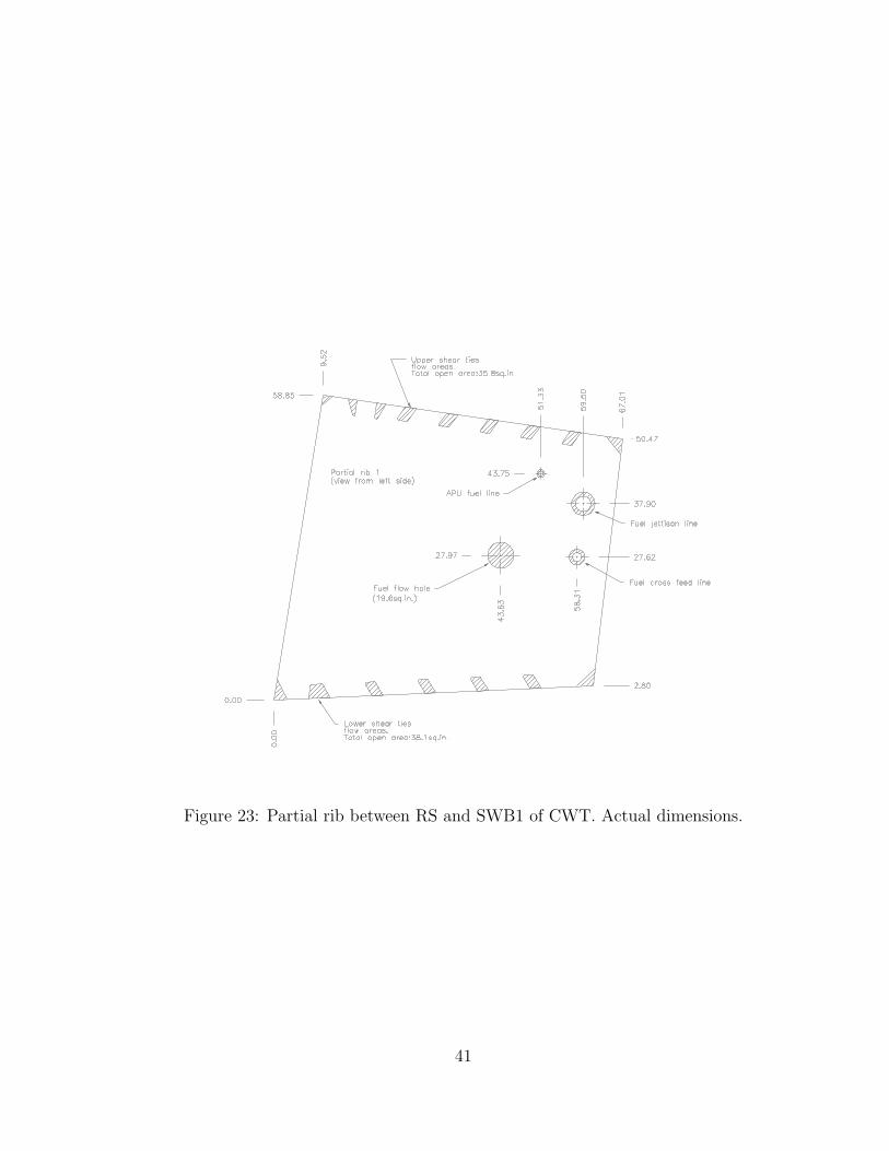
Figure 23: Partial rib between RS and SWB1 of CWT. Actual dimensions.
41

Figure 24: Partial rib between SWB1 and MS of CWT. Actual dimensions.
42

Table 11: Passageways in Spanwise Beam 1 (SWB1).
Passageway Hole dia. Tube OD Flow area Quantity(in.) (in.) (in2)
Lower stringer flow area - - 6.50 2Upper stringer flow area - - 3.30 2Fuel vent 4.25 3.50 4.57 1Refuel manifold 3.00 2.00 3.93 2Jettison 2.75 2.25 1.96 1Scavenge 1.50 1.00 0.98 1Flow hole 2.75 none 5.94 2Total vent area (in2) 46.84
Table 12: Passageways in the Midspar (MS).
Passageway Hole dia. Tube OD Flow area Quantity(in.) (in.) (in2)
Lower stringer flow area - - 6.00 2Upper stringer flow area - - 3.30 2Fuel vent 4.25 3.50 4.57 2Refuel manifold 3.00 1.50 5.30 2Scavenge 1.50 1.00 0.98 1Flow hole 2.53 none 5.03 2Total vent area (in2) 49.37
Table 13: Passageways in Spanwise Beam 2 (SWB2).
Passageway Hole dia. Tube OD Flow area Quantity(in.) (in.) (in2)
Lower stringer flow area - - 5.30 2Upper stringer flow area - - 3.30 2
Fuel vent 4.25 3.50 4.57 2Refuel manifold 2.50 1.50 3.14 2
Flow hole (scavenge) 1.50 none 1.77 1Total vent area (in2) 34.38
43

Table 14: Passageways in the partial rib between the Rear-spar (RS) and the Mid-spar(MS).
Between RS and SWB 1 Between SWB 1 and MSPassageway Hole dia. Tube OD Flow area Flow area
(in.) (in.) (in2) (in2)Lower shear ties - - 38.1 20.4Upper shear ties - - 35.8 24.1Flow hole 5.00 none 19.6 noneAPU fuel line 1.50 1.00 0.98 noneCrossfeed line 3.00 1.75 4.66 noneFuel jettison line 4.50 3.00 8.83 noneTotal flow area 107.98 44.5
44

B 1/4-Scale Facility
Figure 25: Perspective view of assembled 1/4-scale facility.
45

Figure 26: Side view of assembled 1/4-scale facility.
46

Figure 27: End view of assembled 1/4-scale facility.
47

Figure 28: Close-up side view of assembled 1/4-scale facility.
48

Figure 29: Top plate layout for 1/4-scale facility.
49

Figure 30: Bottom plate layout for 1/4-scale facility.
50

Figure 31: Strong partition mounting scheme. 1/4-scale facility.
51

Figure 32: Strong partition mounting holes. 1/4-scale facility.
52

Figure 33: SWB1 hole layout for 1/4-scale facility.
53

Figure 34: MS hole layout for 1/4-scale facility.
54

Figure 35: SWB2 hole layout for 1/4-scale facility.
55

Figure 36: Forward partial rib hole layout for 1/4-scale facility.
56
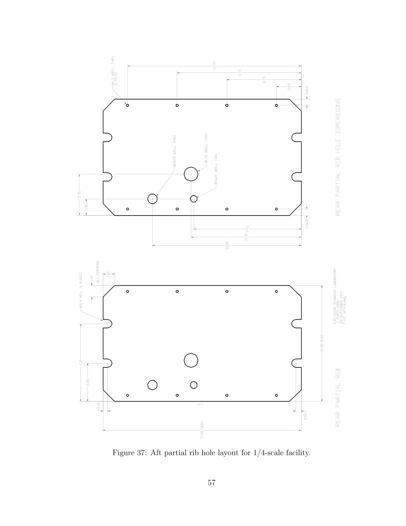
Figure 37: Aft partial rib hole layout for 1/4-scale facility.
57

Figure 38: Window hole layout for 1/4-scale facility.
Figure 39: Window sealing detail for 1/4-scale facility.
58

Figure 40: Plumbing detail for 1/4-scale facility.
59