JC6000 MULTI AXIS JOYSTICK CONTROLLER - Vente … · JC6000 MULTI AXIS JOYSTICK CONTROLLER...
15
JC6000 MULTI AXIS JOYSTICK CONTROLLER Innovation In Motion Wimesure • 54, rue de Versailles • 78460 CHEVREUSE • Tél. 01 30 47 22 00 • Fax 01 30 47 28 29 www.wimesure.fr • [email protected]
-
Upload
nguyenhanh -
Category
Documents
-
view
236 -
download
0
Transcript of JC6000 MULTI AXIS JOYSTICK CONTROLLER - Vente … · JC6000 MULTI AXIS JOYSTICK CONTROLLER...

JC6000 MULTI AXIS JOYSTICK CONTROLLER
Innovation In Motion
Wimesure • 54, rue de Versailles • 78460 CHEVREUSE • Tél. 01 30 47 22 00 • Fax 01 30 47 28 29www.wimesure.fr • [email protected]
Wimesure • 54, rue de Versailles • 78460 CHEVREUSE • Tél. 01 30 47 22 00 • Fax 01 30 47 28 29www.wimesure.fr • [email protected]
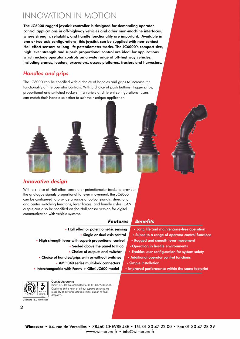
The JC6000 rugged joystick controller is designed for demanding operatorcontrol applications in off-highway vehicles and other man-machine interfaces,where strength, reliability, and handle functionality are important. Available inone or two axis configurations, this joystick can be supplied with non-contactHall effect sensors or long life potentiometer tracks. The JC6000’s compact size,high lever strength and superb proportional control are ideal for applicationswhich include operator controls on a wide range of off-highway vehicles,including cranes, loaders, excavators, access platforms, tractors and harvesters.
INNOVATION IN MOTION
Benefits
• Long life and maintenance-free operation
• Suited to a range of operator control functions
• Rugged and smooth lever movement
•Operation in hostile environments
• Enables user configuration for system safety
• Additional operator control functions
• Simple installation
• Improved performance within the same footprint
Features
• Hall effect or potentiometric sensing
• Single or dual axis control
• High strength lever with superb proportional control
• Sealed above the panel to IP66
• Choice of outputs and switches
• Choice of handles/grips with or without switches
• AMP 040 series multi-lock connectors
• Interchangeable with Penny + Giles' JC600 model
Handles and grips
The JC6000 can be specified with a choice of handles and grips to increase thefunctionality of the operator controls. With a choice of push buttons, trigger grips,proportional and switched rockers in a variety of different configurations, userscan match their handle selection to suit their unique application.
2
Certificate No.LRQ 0924881
Quality AssurancePenny + Giles are accredited to BS EN ISO9001:2000Quality is at the heart of all our systems ensuring thereliability of our products from initial design to finaldespatch.
Innovative designWith a choice of Hall effect sensors or potentiometer tracks to providethe analogue signals proportional to lever movement, the JC6000can be configured to provide a range of output signals, directionaland center switching functions, lever forces, and handle styles. CANoutput can also be specified on the Hall sensor version for digitalcommunication with vehicle systems.•

Cell manufacturedThe modular design of the JC6000 joystick is designed to provide the userwith a wide choice of options, but allows efficient build and despatch usingcell manufacturing principles. Contact your nearest sales office for the latestinformation on availability.
Total reliabilityThe JC6000 includes lever mechanics designed to give smooth proportionalcontrol, with Hall effect sensors that provide contactless, long life operation up to15 million operations. Alternative potentiometer tracks featuring multi-fingeredprecious metal wipers give low electrical noise and a long life of greater than 5million operations.
Custom designPenny+Giles offer an extensive range of fingertip and handoperated joysticks in standard modular configurations,designed to meet the majority of individual customer needs, butwe can customise our designs for OEMs who require somethingmore specialised to their application. Please talk to our technicalsales team about your requirements.
J C 6 0 0 0 M U L T I - A X I S J O Y S T I C K C O N T R O L L E R
3
SafetyThe JC6000 with the Hall sensors option has dual outputsfitted as standard, allowing the signals to be monitored andcompared for failure detection in safety critical applications.Additional independent switch functions can be specified fordirectional and center position indication - vital for vehicle systemstart-up safety. These switch functions are also available with thepotentiometer tracks, which can also be specified with paddingresistors to limit the output signals to 10-90% or 25-75%, allowingcomparison and error detection.
Wimesure • 54, rue de Versailles • 78460 CHEVREUSE • Tél. 01 30 47 22 00 • Fax 01 30 47 28 29www.wimesure.fr • [email protected]

J C 6 0 0 0 J O Y S T I C K C O N T R O L L E R
P E R F O R M A N C EMECHANICAL
Lever operating forcebreakout* Noperating* Nmaximum allowable** N
Lever mechanical anglesingle axis only ºsquare gate º
Seat
Expected life
Weight g
ENVIRONMENTAL
Operating temperature ºC
Storage temperature ºC
Environmental protection(above the flange)
Vibration
Shock
EMC immunity level
EMC emissions level
ESD immunity level
E L E C T R I C A L - H A L L E F F E C T S E N S O RResolution
Supply voltage range Vdc
Over voltage (maximum) Vdc
Reverse polarity (maximum) Vdc
Output voltage span - options Vdc
Load impedance (minimum) kΩCenter voltage (no load) %
Current consumption mA
Insulation resistance
Output sense
Output matching
E L E C T R I C A L C O N N E C T I O N S
Mating 12 way connector and pins
Mating 12 way harness
7 or 1619 or 39 (full deflection)390 (490 overload)
±20 forward/reverse±20 in X and Y directions
preferred bias on axis
15 million operations (5 million for potentiometer track version)
750 without handle fitted
-25 to +80 (-25 to +80 with microswitches)
-25 to +85 (-25 to +85 with microswitches)
IP66 IEC 60529 (fitted with HKN handle)
Level±3g,10Hz to 200Hz (random) @ 3.6g(rms)
20g, 6mS, half sine profile
100V/m, 30MHz to 1GHz, 1KHz 80% sine wave modulation, EN50082-2 (1995)
Complies with EN50081-2 (1993), 150kHz to 30MHz, level B
IEC61000-4-2 level 4 8kV contact discharge, 15kV air discharge
Infinite
5 ±0.5 regulated transient free
15 continuous
14.5
±25% span - nominal 1.1 to 3.9
±30% span - nominal 1.0 to 4.0
±40% span - nominal 0.5 to 4.5
5
48 - 52 of supply voltage
13 per axis (6.5 per sensor)
Greater than 50MΩ at 50Vdc
The dual outputs rise together in the same direction, increasing with lever forward (and right),decreasing with lever backward (and left)
See maximum output difference diagram below
All Hall sensor connections terminate in a 12-way AMP 040 series multi-lock connector in thejoystick base. See page 8 for pin identities
SA48061 (AMP 040 12 way connector 174045-2; pins 175062-1)
P49779 (connector, pins and 380mm long cable)
4
* Measured at 55mm above upper flange face ** Measured 130mm above upper flange face
Wimesure • 54, rue de Versailles • 78460 CHEVREUSE • Tél. 01 30 47 22 00 • Fax 01 30 47 28 29www.wimesure.fr • [email protected]

E L E C T R I C A L -P O T E N T I O M E T E R T R A C KResolution
Track resistance ±20% kΩTrack operating angle º
Output voltage range %
Center tap voltage %
Center tap angle º
Center tap to switch alignment º
Supply voltage maximum Vdc
Wiper circuit impedance MΩPower dissipation @ 25°C W
Insulation resistance
E L E C T R I C A L -D I R E C T I O N A L O R C E N T E RS W I T C H ( L O W C U R R E N T )Switch operating angle º
Supply voltage maximum Vdc
Load current maximum mA
E L E C T R I C A L C O N N E C T I O N S
Mating 16 way connector and pins
Mating 16 way harness
Mating 8 way connector and pins
Mating 8 way harness
E L E C T R I C A L -M I C R O S W I T C HSwitch configuration
Switch operating angle º
Contact rating
Switch life minimum
Operating temperature ºC
E L E C T R I C A L C O N N E C T I O N S
C A N O U T P U T V E R S I O N
Supply voltage range Vdc
CAN version
Protocol
Under-panel sealing
E L E C T R I C A L C O N N E C T I O N SMating connector and pins
Virtually infinite
1.8, 2, 2.9, 5
±18
0-100, 10-90, 25-75 of input
48 - 52 of applied voltage
±2.5
Within 0.5
32
1 minimum recommended*
0.25
Greater than 15MΩ at 50Vdc* The long life resistive elements require a high impedance load in the wiper circuit to minimisethe current flowing through the wiper for optimum life conditions
Not available with CANbus output
1.5 or 5 either side of center
35
200 resistive
All primary potentiometer track and directional/center switch connections terminate in a 16-wayAMP 040 series multi-lock connector in the joystick base. Secondary potentiometer trackconnections terminate in an 8-way AMP 040 series multi-lock connector. See page 8 forpin identities
SA47931 (AMP 040 16 way connector 174046-2; Pins 175062-1)
P49780 (connector, pins and 380mm long cable)
SA304522 (AMP 040 8 way connector 174044-2; pins 175062-1)
P303083 (connector, pins and 380mm long cable)
Not available with CANbus output
Two switches per axis. Normally open at lever center position
2 to 5 either side of center
3A @125Vac, 2A @ 30Vdc
100,000 cycles, cycled at 1Hz, 1A and 12Vdc
-25 to +85
Microswitch connections in the potentiometer joystick will replace the low currentdirectional/center switches in the 16-way AMP 040 series multi-lock connector in the joystickbase. In the Hall sensor joystick, switches terminate in the 8-way connector. See ElectricalConnections on page 8 for pin identities
JC6000 with Hall sensing option can also be supplied with an integrated CANBUS outputoffering the J1939 protocol. This CANBUS interface meets the requirements of IEC61508 SIL level 1
9 to 36
CAN 2.0b
J1939
IP66 IEC60529
All connections terminate in the 6-way Deutsch DTM04-6P integrated connector
P304844 (includes 390mm flying leads)
5
Wimesure • 54, rue de Versailles • 78460 CHEVREUSE • Tél. 01 30 47 22 00 • Fax 01 30 47 28 29www.wimesure.fr • [email protected]

J C 6 0 0 0 J O Y S T I C K C O N T R O L L E R H O W T O S P E C I F Y
A X E S
S E N S I N GOutput
Output
L E V E R S P R I N G F O R C E
G AT E
M E C H A N I C A LF E AT U R E S
M I C R O S W I T C H
I N T E R F A C E
H A N D L E / G R I P S T Y L ESee pages 9-15
PERFORMANCE OPTIONS CODESingle NY
Dual XY
Potentiometer Px or Pxx selected from below P
5k 0-100%, ±5º directional switch E
1.8k 0-100%, ±5º directional switch N
2.9k 25-75%, ±1.5º directional switch Q
2k 10-90%, ±1.5º directional switch R
2k 10-90%, ±5º directional switch S
2.9k 25-75%, ±5º directional switch T
Dual outputs per axis, 2k 10-90%, ±1.5º directional switch U
Dual Hall Effect sensors each axis Hxx with output selected from below H
Dual Hall Effect sensors each axis and ±1.5º directional switch Bxx with output B
selected from below
1.1Vdc to 3.9Vdc K
1.0Vdc to 4.0Vdc L
0.5Vdc to 4.5Vdc M
CANbus Output HC
Single Axis/Dual Axis 1 or 2
Note: Directional track switches not currently available with CANbus output.
Heavy duty, 16N breakout, 39N full deflection H
Medium duty, 7N breakout,19N full deflection M
Square ±20º mechanical angle in X and Y directions S
No lock or detents fitted NL
No switch fitted N
High current microswitches, 2A @ 30Vdc (Not available with CANbus output) Y
Standard interface (no electronics) STN
CANbus output, SAE J1939 protocol, Source Address 33 (HEX) JR1
1000 CAN counts Source Address 34 JL1
Source Address 35 JC1
Source Address 36 JA1
Standard knob, no functions HKN
Hand grip with options for buttons or rocker HB
Ergonomic grip with multiple buttons and proportional rockers A
Trigger grip with optional rocker switching MG
No handle NH
No handle, flying leads fitted (allows customer to fit own handle.) NHF
E X A M P L E O R D E R C O D E XY- PRR - H - S - NL - N - STN - HKNJC6000 -
6
Wimesure • 54, rue de Versailles • 78460 CHEVREUSE • Tél. 01 30 47 22 00 • Fax 01 30 47 28 29www.wimesure.fr • [email protected]

J C 6 0 0 0 J O Y S T I C K C O N T R O L L E R
D I M E N S I O N SNote: drawings not to scale
I N S TA L L AT I O NThe joystick is designed to be fitted from
below the mounting panel, through a
70mm diameter hole. The effectiveness of
the joystick flange sealing is dependent on
the panel mounting surface being
sufficiently rigid to compress the sealing
gaiter. The surface finish of the mounting
panel is critical to achieving an adequate
seal and rough surface finishes, paint
chips, deep scratches, etc. should be
avoided.
Recommended panel thickness
3.5 to 6mm
Recommended screw torque
Fixing screws can be driven to a maximum
torque of 5Nm when clamped against a
3.5mm thick panel.
The mounting hole depth is 12.6mm. For
through-hole installation, the screws can
be driven at a torque of 3.5Nm directly
through the blind cast holes to remove the
cast covers. The joystick mounting flange
should be connected to the vehicle chassis
or reference plane (normally zero volts).
CAN OUTPUT CONTROLLERPOTENTIOMETER AND HALL EFFECTCONTROLLER
7
C A N O U T P U T O P T I O N SThe sealing of the lower cover meets the
requirements of IP66 (IEC 60529) and uses
an integrated Deutsch DTM04-6P 6 pin
connector with the cover. The use of a
suitable sealed mating connector will
enable a full IP66 connection to be made.
The cover also includes an integrated
breather system to ensure pressure
regulation under all barometric pressure
and temperature conditions without
moisture ingress into the joystick.
See next page for electrical connections
61 mountingscrew centers
M6 Torx T30 supplied(4 places)
61 mountingscrew centers
M6 Torx T30 supplied(4 places)
ø11.93/12.00ø9.518/9.548
ø11.93/12.00ø9.518/9.548
Joystick mountingsurface
80 (includes gaiter)Pin 1
Pin 1
Forwardorientation
ident on thisface
Pin 9
Pin 7
8-way connectorsecondary pot interface(Switch connections on
Hall version).
12-way connectorHall sensor interface
(handle on potentiometerversion)).
Forwardorientation
ident
Pin 1Pin 1
Pin 5
16-way connectorPotentiometer interface(Handle on Hall version)
68 (m
ax)
150
(nom
inal
)
74 (m
ax)
329.
7
329.
7
ø 3.218/3.2 ø 3.218/3.2
Wimesure • 54, rue de Versailles • 78460 CHEVREUSE • Tél. 01 30 47 22 00 • Fax 01 30 47 28 29www.wimesure.fr • [email protected]

E L E C T R I C A L C O N N E C T I O N S
16-way primary connector
8-way secondary connector (where fitted)
12-way connector
6 pin Deutsch connector CAN output
Pin number Potentiometer tracks Hall effect sensors
1 Y switch track N/O (lever forward +Y) Pins 1 to 12 used for handle connections
2 X switch track center on See chosen handle style for details
3 X pot track left -
4 X pot track wiper signal -
5 X pot track right -
6 X pot track center tap -
7 X switch track common -
8 X switch track N/O (lever left -X) -
9 Y pot track backward -
10 Y pot track wiper signal -
11 Y pot track forward -
12 Y pot track center tap -
13 Y switch track common Not connected
14 Y switch track N/O (lever backward -Y) Not connected
15 X switch track N/O (lever right +X) Not connected
16 Y switch track center on Not connected
1 Secondary Y pot track backward Forward (directional or micro) switch common
2 Secondary Y pot track center tap Forward switch output
3 Secondary Y pot track wiper signal Backward switch output
4 Secondary Y pot track forward Backward switch common
5 Secondary X pot track right Left switch common
6 Secondary X pot track wiper signal Left switch output
7 Secondary X pot track center tap Right switch output
8 Secondary X pot track left Right switch common
1 Pins 1 to 12 used for handle connections +5V supply - sensors 3 and 4
2 See chosen handle style for connection details 0V supply - sensors 3 and 4
3 - +5V supply - sensors 1 and 2
4 - 0V supply - sensors 1 and 2
5 - Forward/backward output - sensor 3
6 - Left/right output - sensor 2
7 - Left/right output - sensor 4
8 - Forward/backward output - sensor 1
9 - Not connected
10 - Not connected
11 - Not connected
12 - Not connected
1 Not available Ground
2 Not available Power
3 Not available CAN high
4 Not available CAN low
5 Not available CAN shield
6 Not available Not connected
J C 6 0 0 0 J O Y S T I C K C O N T R O L L E R
8
Wimesure • 54, rue de Versailles • 78460 CHEVREUSE • Tél. 01 30 47 22 00 • Fax 01 30 47 28 29www.wimesure.fr • [email protected]

9
J C 6 0 0 0 J O Y S T I C K C O N T R O L L E RH A N D L E O P T I O N S
MGDesigned to provide a simple approach to a ‘Person Present’ handle whilst offering the
flexibility of switch options in the top of the handle. The profile of the MG handle
ensures the operator's fingers are permanently close to the buttons, minimising operator
fatigue and maximising functional control. The handle can be supplied with or without
a hand rest and can be configured with a combination of trigger lever, single or dual
switches.
This handle can also be purchased separately, for fitting to customer levers or
assemblies. Ask our sales team for more details on this option.
HKNThe HKN handle is the simplest option
available for the JC6000. This handle does
not include any additional functionality, but is
designed to allow the joystick to be controlled
by the operator gripping the handle palm
downwards.
NH or NHFThese options are selected when
no handle is required to be fitted.
NHF option has wires fitted to the
joystick connector on the base,
through the operating lever.
HBDeveloped to replicate the functionality of the
traditional mechanical handle, the HB range of
hand grips can be specified with either a button
or rocker switch, mounted into the top of the
handle, within easy reach of the operator’s
thumb. These can be configured as a ‘Person
Present’ feature or, for example, the steer
signal for an access platform.
A RANGEDesigned to meet the demands for more complex control systems in off-highway
applications, the 'A' range of ergonomic hand grips can be fitted with a combination
of analogue outputs, push button and ‘Person Present’ switches. The handle can be
specified with two independent analogue outputs generated by proportional rockers
which, in turn, provide auxiliary directional switching in addition to the potentiometric
output. When coupled with the two axis JC6000 base joystick this unit can provide a
four-axis controller.
This handle can also be purchased separately, for fitting to customer levers or
assemblies. Ask our sales team for more details on this option.
Wimesure • 54, rue de Versailles • 78460 CHEVREUSE • Tél. 01 30 47 22 00 • Fax 01 30 47 28 29www.wimesure.fr • [email protected]

10
H K N H A N D L E O P T I O N
N H O R N H F H A N D L E O P T I O N SE L E C T R I C A L C O N N E C T I O N SWire size
Wire current
ø35
45
110
max
250
min
DIMENSIONS
28AWG
1.4A
NHF handle option note: Wires terminate on the 12-way connector (Potentiometer
version), or the 16-way connector (Hall sensor version).
NH option has no wires fitted.
NHF option allows customer to
fit own handle style to joystick
operating lever.
Pin Wire color
1 Grey
2 Yellow
3 Red
4 Orange
5 Brown
6 Black
7 Green
8 White
9 Blue
10 Violet
11 Pink
12 Red/Yellow
13 Not connected
14 Not connected
15 Not connected
16 Not connected
see page 7 for lever dimensions
Wimesure • 54, rue de Versailles • 78460 CHEVREUSE • Tél. 01 30 47 22 00 • Fax 01 30 47 28 29www.wimesure.fr • [email protected]

HB0 HB1 HB2 HBD
H B H A N D L E O P T I O N S
11
S P E C I F I C AT I O N H B O H B 1 H B 2 H B D
Maximum height above flange mm 149 155 155 164
Maximum grip diameter mm 35 35 35 35
Environmental sealing (IEC 60529) IP65 IP65 IP65 IP65
Number of switches 0 1 2 1
Action Momentary rocker Momentary rocker Momentary button
Switch operating force N - - - 7
Maximum current @ 30Vdc A - 2.5 2.5 5
Expected life (operations) 100,000 100,000 100,000 100,000
E L E C T R I C A L C O N N E C T I O N SCommon terminal 11 11 11
N/O contact switch 1 4 4 1
N/C contact switch 1 1
N/O contact switch 2 1
Note: Signals terminate on the 12 way connector (potentiometer version) or the 16 way connector (Hall sensor version)
155
155
164
ø35
115
149
max
DIMENSIONS
Wimesure • 54, rue de Versailles • 78460 CHEVREUSE • Tél. 01 30 47 22 00 • Fax 01 30 47 28 29www.wimesure.fr • [email protected]

S P E C I F I C AT I O NMaximum height above flange mm
Maximum grip diameter mm
Environmental sealing
(IEC 60529)
Number of switches
Action
Switch operating force N
Maximum current @ 50Vdc mA
Expected life (operations)
Weight g
Operating temperature ºC
Storage temperature ºC
166
61
IP65
1 to 6 in the top plate
Momentary button
3
200
1 million
170 - A2LD option
-40 to +70
-40 to +80
A R A N G E H A N D L E O P T I O N S
12
S W I T C H A N D R O C K E R O P T I O N S
R O C K E RRocker profile
Breakout force N
Operating force N
Mechanical movement º
Electrical movement º
Expected life (operations)
Load current (maximum) mA
Power dissipation @ 25ºC W
Track resistance
Output voltage
Center tap angle º
Directional or center off switch
Switch gap º
Switch supply voltage Vdc
Standard (S) or V profile (V)
5 at the end of the rocker
15 at the end of the rocker
±10 (±1°)
±9 (±1°)
5 million
200 (see note on page 5)
0.25
Will match JC6000 Y axis resistance †
Will match JC6000 Y axis output †
±1.5
Standard
2.5 either side of center
35† unless requested otherwise
F U N C T I O N A L I T Y S W I T C H E S R O C K E R S
1 2 3 4 5 6 TOP Person Present LEFT RIGHT HORIZONTAL
S W I T C H 1S W I T C H 2S W I T C H 3S W I T C H 4S W I T C H 5S W I T C H 6T O P S W I T C HP E R S O N P R E S E N T
L E F T R O C K E RR I G H T R O C K E RH O R I Z O N TA L
A000A00TA00DA00B
1
3 2
4 1
3
4 1
5
2
3
3
2
2
1
3
4 1
5
6
2 2
2 3
3 3
4
4
2
2
5
3
6
1
1
1
A100A10TA10DA10B
A200A20TA20DA20B
A300A30TA30DA30B
A400A40TA40DA40B
A500A50TA50DA50B
A600A60TA60DA60B
AOLOAOLTAOLDAOLB
A1LOA1LTA1LDA1LB
A2LOA2LTA2LDA2LB
A3LOA3LTA3LDA3LB
AOROAORTAORDAORB
A1ROA1RTA1RDA1RB
A2ROA2RTA2RDA2RB
A3ROA3RTA3RDA3RB
AOBOA0BD
A0H0A0HD
A1HOA1HD
A2H0A2HD
Wimesure • 54, rue de Versailles • 78460 CHEVREUSE • Tél. 01 30 47 22 00 • Fax 01 30 47 28 29www.wimesure.fr • [email protected]
13
O R D E R I N G C O D E S A - 2 - L - D - R - S
Push button select 1 to 6 in the top plate
Additional switchesO = NoneT = TopD = Person Present (Deadmans)B = Both
Rocker positionO = NoneL = LeftR = RightB = BothH = Horizontal
Note: When ordering a handle fitted with a rocker, two profiles can be supplied (S = standard profile; V = v profile) please specify style when ordering.
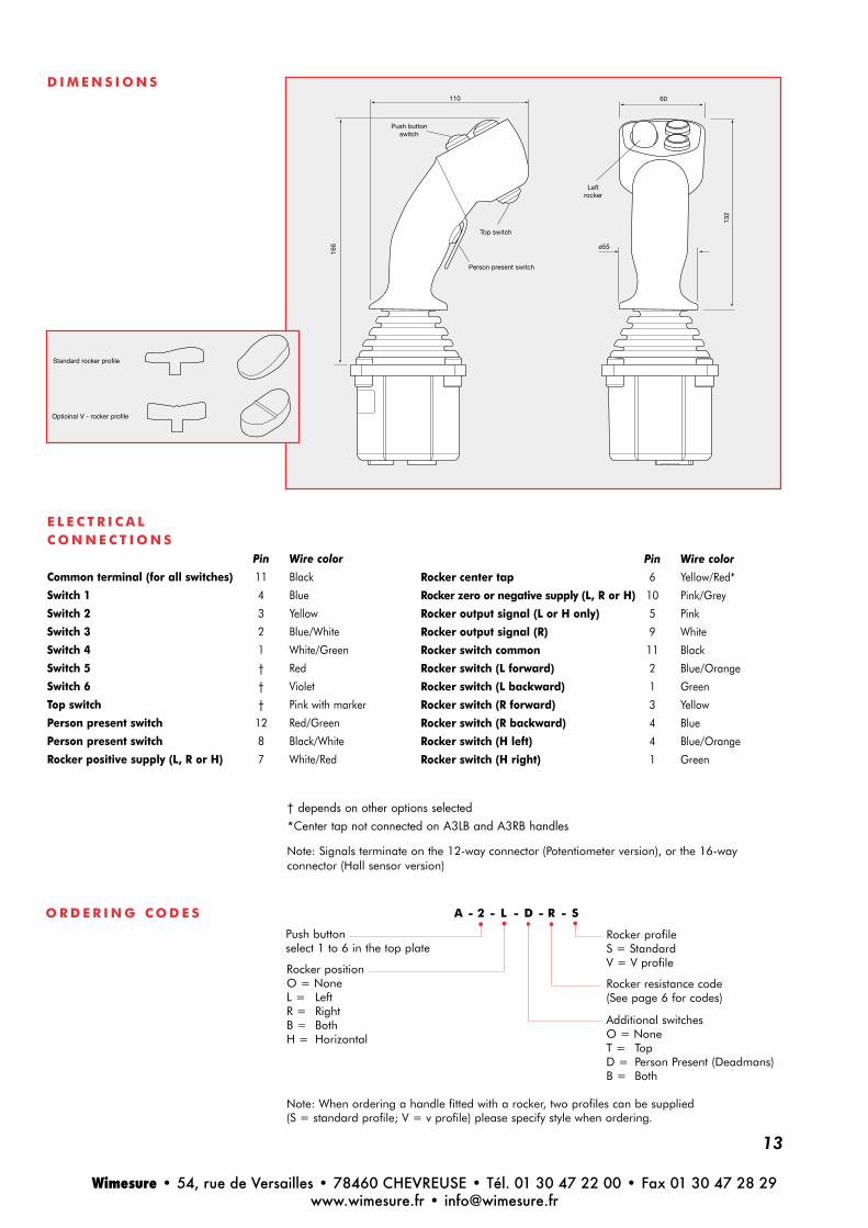
D I M E N S I O N S
E L E C T R I C A L C O N N E C T I O N S
Pin Wire color
Common terminal (for all switches) 11 Black
Switch 1 4 Blue
Switch 2 3 Yellow
Switch 3 2 Blue/White
Switch 4 1 White/Green
Switch 5 † Red
Switch 6 † Violet
Top switch † Pink with marker
Person present switch 12 Red/Green
Person present switch 8 Black/White
Rocker positive supply (L, R or H) 7 White/Red
Pin Wire color
Rocker center tap 6 Yellow/Red*
Rocker zero or negative supply (L, R or H) 10 Pink/Grey
Rocker output signal (L or H only) 5 Pink
Rocker output signal (R) 9 White
Rocker switch common 11 Black
Rocker switch (L forward) 2 Blue/Orange
Rocker switch (L backward) 1 Green
Rocker switch (R forward) 3 Yellow
Rocker switch (R backward) 4 Blue
Rocker switch (H left) 4 Blue/Orange
Rocker switch (H right) 1 Green
† depends on other options selected*Center tap not connected on A3LB and A3RB handles
Note: Signals terminate on the 12-way connector (Potentiometer version), or the 16-wayconnector (Hall sensor version)
Rocker profileS = StandardV = V profile
Rocker resistance code(See page 6 for codes)
110
166
132
60
ø55
Top switch
Push buttonswitch
Leftrocker
Person present switch
Standard rocker profile
Optioinal V - rocker profile
Wimesure • 54, rue de Versailles • 78460 CHEVREUSE • Tél. 01 30 47 22 00 • Fax 01 30 47 28 29www.wimesure.fr • [email protected]

S P E C I F I C AT I O NMaximum height above flange mm
Maximum grip diameter mm
Environmental sealing (IEC 60529)
Number of switches
Action
Switch operating force
Trigger N
Switch 1 or 2 N
Maximum current @ 30Vdc mA
Expected life (operations)
Operating temperature ºC
Storage temperature ºC
168
40
IP67 (IP66 with trigger switch)
0 to 3
Momentary Button, Rocker or Trigger
5
7
100
1 million
-25 to +75
-30 to +80
M G H A N D L E O P T I O N SD I M E N S I O N S
14
54
Switch 1/2
Switch 1
Switch 2
14
Trigger114
168
28
ø62.
5
ø40
Wimesure • 54, rue de Versailles • 78460 CHEVREUSE • Tél. 01 30 47 22 00 • Fax 01 30 47 28 29www.wimesure.fr • [email protected]

15
Top switch position Trigger switch Hand rest
None No No
1 No No
1 & 2 No No
1 & 2 Yes No
1 & 2 Yes Yes
1 Yes Yes
1 & 2 No Yes
1 No Yes
1 Yes No
None Yes Yes
None None Yes
None Yes NoSee Electrical Connections for wire color codes.
HANDLE CODEMG00
MG01
MG02
MG03
MG04
MG05
MG06
MG07
MG08
MG09
MG10
MG11
E L E C T R I C A LC O N N E C T I O N SCommon terminal (for top switches)
Switch 1- Left
Switch 2 - Right
Trigger switch
Trigger switch
Pin number Wire color
12 Black
6 Blue
3 Green
4 Blue/Orange
5 Yellow
Note: Signals terminate on the 12-way connector (Potentiometer version), or the 16-wayconnector (Hall sensor version)
Wimesure • 54, rue de Versailles • 78460 CHEVREUSE • Tél. 01 30 47 22 00 • Fax 01 30 47 28 29www.wimesure.fr • [email protected]