
Japan Fiscal Year 2009 Summer Launch Season Launch ... · Japan Fiscal Year 2009 Summer Launch...
27
Japan Fiscal Year 2009 Summer Launch Season Launch/Operation and Control Plans for H-II Transfer Vehicle (HTV) Demonstration Flight H-IIB Launch Vehicle Test Flight (H-IIB TF1) July 2009 Japan Aerospace Exploration Agency (JAXA) (Independent Administrative Agency)
-
Upload
truonghuong -
Category
Documents
-
view
216 -
download
0
Transcript of Japan Fiscal Year 2009 Summer Launch Season Launch ... · Japan Fiscal Year 2009 Summer Launch...

Japan Fiscal Year 2009 Summer Launch Season
Launch/Operation and Control Plans for
H-II Transfer Vehicle (HTV) Demonstration Flight
H-IIB Launch Vehicle Test Flight (H-IIB TF1)
July 2009
Japan Aerospace Exploration Agency (JAXA) (Independent Administrative Agency)
i
Table of Contents Page
1. Overview 1 1.1 Organization in Charge of Launch/Operation and Control 1 1.2 Person in Charge of Launch/Operation and Control 1 1.3 Objectives of Launch/Operation and Control 2 1.4 Launch Vehicle and Payload 2 1.5 Launch Window (Day and Time) 2 1.6 Facilities for Launch/Operation and Control 2
2. Launch Plan 3 2.1 Launch Site 3 2.2 Launch Organization 3 2.3 Launch Vehicle Flight Plan 4 2.4 Major Characteristics of the Launch Vehicle 4 2.5 Securing Launch Safety 4 2.6 Correspondence Method of Launch Information to Parties Concerned 5 2.7 Launch Result Report 5
3. Operation and Control Plan of the H-II Transfer Vehicle (HTV) Demonstration Flight 6 3.1 Operation and Control Site 6 3.2 Operation and Control Organization 7 3.3 Flight Plan of the HTV Demonstration Flight 8 3.4 Major Characteristics of the HTV Demonstration Flight 8 3.5 Safety Securing Method for Re-entry 8 3.6 Correspondence Method of Re-entry Information 8 3.7 Operation and Control Result Report 8
[List of Figures] Figure 1: Map of Launch/Operation and Control Facilities 9 Figure 2-1: Launch Vehicle Flight Trajectory 11 Figure 2-2: Configuration of the H-IIB Launch Vehicle 13 Figure 2-3: Access Control Areas for Launch 14 Figure 2-4: Impact Areas of the Launch Vehicle 16 Figure 3-1: Operation and Control System Configuration of the HTV Demonstration
Flight 17 Figure 3-2: Overview of the HTV Demonstration Flight Operation Plan 19 Figure 3-3: Configuration of the HTV Demonstration Flight 23 Figure 3-4: Re-entry Flight Path 24 Figure 3-5: Acceptable Impact Area for Water Landing 25
[List of Tables] Table 2-1: Launch Vehicle Flight Plan 10 Table 2-2: Major Characteristics of the Launch Vehicle 12 Table 3-1: Operation Plan for the HTV Demonstration Flight 18 Table 3-2: Operation and Control Stations Plan for the HTV Demonstration Flight 20 Table 3-3: Major Characteristics of the HTV Demonstration Flight 21

- 1 -
1. Overview The Japan Aerospace Exploration Agency (hereinafter referred to as “JAXA”), an independent administrative agency, is scheduled to carry out the launch of the H-II Transfer Vehicle Demonstration Flight (hereinafter referred to the “HTV Demonstration Flight”) using the H-IIB Launch Vehicle Test Flight (hereinafter referred to the “H-IIB TF1”) in the summer launch season in Japanese Fiscal Year 2009. This document explains the launch plan for the HTV Demonstration Flight from the time of the liftoff of the H-IIB TF1 through the confirmation of the payload separation from the second stage of the launch vehicle, as well as the operation and control plan of the HTV Demonstration Flight. (HTV stands for H-II Transfer Vehicle.)
1.1 Organization in Charge of Launch/Operation and Control
Japan Aerospace Exploration Agency (Independent Administrative Agency) President: Keiji Tachikawa Address: 7-44-1 Jindaiji Higashi-machi, Chofu-shi, Tokyo, 182-8522 Japan
1.2 Person in Charge of Launch/Operation and Control
(1) Director General for Launch Jiro Kouchiyama, Executive Director
(2) Director General for Operation and Control Kuniaki Shiraki, Executive Director

- 2 -
1.3 Objectives of Launch/Operation and Control
To inject the HTV Demonstration Flight into its scheduled orbit using the H-IIB TF1, and to carry out the HTV Demonstration Flight operation and control.
1.4 Launch Vehicle and Payload
Launch Vehicle: One unit of the H-IIB Launch Vehicle Test Flight Payload: One unit of the H-II Transfer Vehicle (HTV) Demonstration Flight
1.5 Launch Window (Day and Time)
Launch Vehicle Type
Scheduled Launch Day (Japan Standard
Time)
Scheduled Launch Time (*1)
(Japan Standard
Time)
Launch Window
Time of the Launch Vehicle Jettison
(After liftoff)
H-IIB Launch Vehicle Test Flight (H-IIB TF1)
Sept. 11, 2009
2:04 a.m.
Between Sept. 12 thru. 30, 2009 (*2)
- Solid rocket boosters: about 6 to 10 minutes after liftoff.
- Payload fairing: about 10 to 24 minutes after liftoff.
- First stage: about 14 to 20 minutes after liftoff.
*1 The launch time will be finalized based on the updated orbit of the International Space Station (ISS.) *2 The launch time during the launch window will be determined according to the international coordination for
the ISS operation. 1.6 Facilities for Launch/Operation and Control
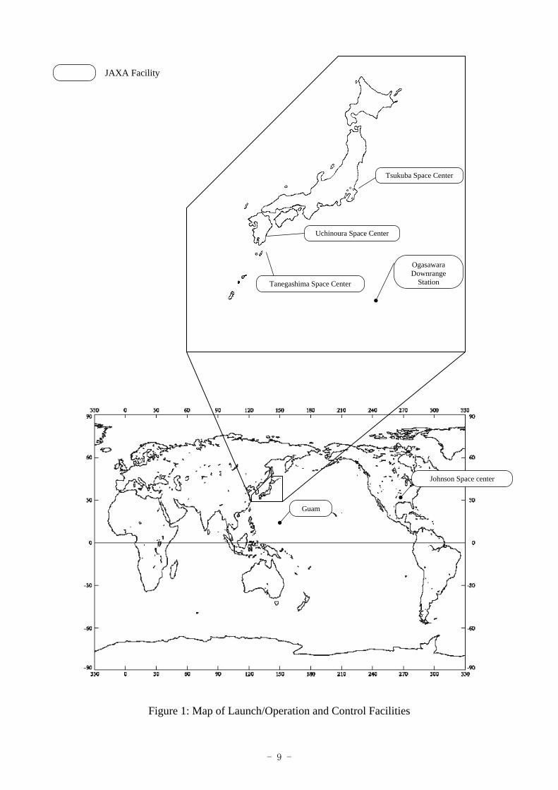
Figure-1 shows the facilities of JAXA and organizations that will support JAXA for the launch, operation, and control.

- 3 -
2. Launch Plan 2.1 Launch Site
(1) JAXA Facility (a) Tanegashima Space Center
Oaza-Kukinaga, Minamitane-machi, Kumage-gun, Kagoshima, Japan (b) Ogasawara Downrange Station
Kuwanokiyama, Chichijima, Ogasawara-mura, Tokyo (c) Uchinoura Space Center
Minamikata, Kimotsuki-cho, Kimotsuki-gun, Kagoshima (d) Guam Downrange Station
Guam, Island, U.S.A 2.2 Launch Organization
The following Launch Team led by the Director General for Launch is organized for smooth and accurate operations of launch site activities, the launch itself and HTV Demonstration Flight orbit injection.
*Note: Each group is responsible for its general affairs, external affairs and public affairs.
Launch Team Organization
Launch Vheicle Group
Ground Facility Group
Range Group
Guard Group
Planning Group
Range Safety Group
Jiro Kouchiyama, Executive Director of
the Space Transportation
Mission Directorate
Takahisa Sato Director of Range Safety Control Office
Kagoshima Space Center
Flight Safety Director
Toru Samejima Manager of Ground Safety Control Division,
Range Safety Control Office Kagoshima Space Center
Range Safety Director
Takashi Nishida Director of Range Technology Development Office
Kagoshima Space Center
Tomihisa Nakamura H-IIB Project Manager
Launch Vehicle Director
Flight Safety Group
Norio Sakazume Director of the
Kagoshima Space Center
Director General for
Launch
Deputy Director General
for Launch
Assistant to the Director General for
Launch
Director For
Legal Security
Planning and Management Director
- 4 -
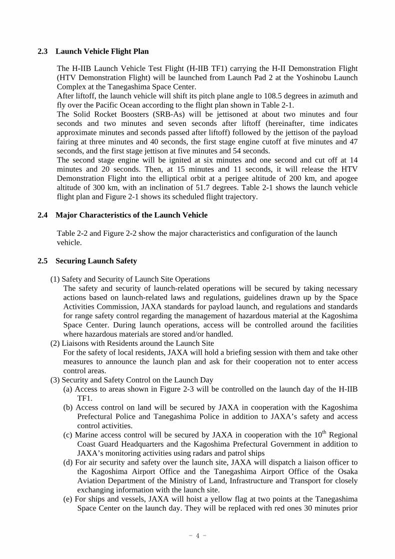
2.3 Launch Vehicle Flight Plan
The H-IIB Launch Vehicle Test Flight (H-IIB TF1) carrying the H-II Demonstration Flight (HTV Demonstration Flight) will be launched from Launch Pad 2 at the Yoshinobu Launch Complex at the Tanegashima Space Center. After liftoff, the launch vehicle will shift its pitch plane angle to 108.5 degrees in azimuth and fly over the Pacific Ocean according to the flight plan shown in Table 2-1. The Solid Rocket Boosters (SRB-As) will be jettisoned at about two minutes and four seconds and two minutes and seven seconds after liftoff (hereinafter, time indicates approximate minutes and seconds passed after liftoff) followed by the jettison of the payload fairing at three minutes and 40 seconds, the first stage engine cutoff at five minutes and 47 seconds, and the first stage jettison at five minutes and 54 seconds. The second stage engine will be ignited at six minutes and one second and cut off at 14 minutes and 20 seconds. Then, at 15 minutes and 11 seconds, it will release the HTV Demonstration Flight into the elliptical orbit at a perigee altitude of 200 km, and apogee altitude of 300 km, with an inclination of 51.7 degrees. Table 2-1 shows the launch vehicle flight plan and Figure 2-1 shows its scheduled flight trajectory.
2.4 Major Characteristics of the Launch Vehicle Table 2-2 and Figure 2-2 show the major characteristics and configuration of the launch vehicle.
2.5 Securing Launch Safety
(1) Safety and Security of Launch Site Operations
The safety and security of launch-related operations will be secured by taking necessary actions based on launch-related laws and regulations, guidelines drawn up by the Space Activities Commission, JAXA standards for payload launch, and regulations and standards for range safety control regarding the management of hazardous material at the Kagoshima Space Center. During launch operations, access will be controlled around the facilities where hazardous materials are stored and/or handled.
(2) Liaisons with Residents around the Launch Site For the safety of local residents, JAXA will hold a briefing session with them and take other measures to announce the launch plan and ask for their cooperation not to enter access control areas.
(3) Security and Safety Control on the Launch Day (a) Access to areas shown in Figure 2-3 will be controlled on the launch day of the H-IIB
TF1. (b) Access control on land will be secured by JAXA in cooperation with the Kagoshima
Prefectural Police and Tanegashima Police in addition to JAXA’s safety and access control activities.
(c) Marine access control will be secured by JAXA in cooperation with the 10th Regional Coast Guard Headquarters and the Kagoshima Prefectural Government in addition to JAXA’s monitoring activities using radars and patrol ships
(d) For air security and safety over the launch site, JAXA will dispatch a liaison officer to the Kagoshima Airport Office and the Tanegashima Airport Office of the Osaka Aviation Department of the Ministry of Land, Infrastructure and Transport for closely exchanging information with the launch site.
(e) For ships and vessels, JAXA will hoist a yellow flag at two points at the Tanegashima Space Center on the launch day. They will be replaced with red ones 30 minutes prior

- 5 -
to the liftoff time. A signal flare will be fired two minutes prior to the liftoff. Two flares will be fired after the launch, and then the red flags will be removed.
(4) Flight Safety of the Launch Vehicle Flight safety of the launch vehicle after liftoff will be monitored and determined by acquired data from the launch vehicle. Any necessary action will be taken based on this data.
2.6 Correspondence Method of Launch Information to Parties Concerned
(1) Correspondence regarding Launch Implementation
(a) A decision on whether the launch will be held as scheduled or delayed will be finalized by 3:00 p.m. two days prior to the scheduled launch day, and that decision will be conveyed to all related organizations listed in a separate document by facsimile.
(b) In case the launch is delayed due to adverse weather conditions and/or other factors, the postponement and new launch date will be swiftly informed to all related organizations.
(c) JAXA will announce the status of the launch two days prior to the launch day, then six hours, two hours and thirty minutes prior to launch, and again just after liftoff, to the following parties: the New Tokyo Airport (Narita Airport) Office of the Tokyo Aviation Department, the Kagoshima Airport Office and the Tanegashima Airport Office of the Osaka Aviation Department, the Air Traffic Control Center of the Civil Aviation Bureau, and Air Traffic Control Centers in Tokyo, Fukuoka, and Naha.
(2) Prior Notice and Launch Information Announcement for Maritime Traffic Safety
(a) JAXA will request the Hydrographic and Oceanographic Department of the Japan Coast Guard to publish a notice to mariners regarding the marine access control areas shown in Figure 2-3 (2/2) and the impact areas shown in Figure 2-4.
(b) For general navigation ships and vessels, JAXA will announce the launch activity, in addition to the notice for mariners, through radio navigation warnings and shipping broadcasts by Kyodo News Enterprise (a navigation warning offered by the Japan Coast Guard).
(c) For fishing boats, JAXA will announce the launch activity through fishery radio stations, and the shipping broadcast of Kyodo News Enterprise (a navigation warning offered by the Japan Coast Guard).
(3) Prior Notice and Launch Information Announcement for Air Traffic Safety
(a) Air traffic safety will be secured through a supplement of the Aviation Information Publication and the Notice of Airman (NOTAM) issued by the Ministry of Land, Infrastructure, and Transport (MLIT). JAXA will place the request well in advance to the MLIT according to Article 99, Section 2, of the Aviation Act and its related regulations, so that the supplement will be promptly issued by the Civil Aviation Bureau of the MLIT. The information necessary for issuing the NOTAM will also be conveyed to the Aeronautical Information Service Centers.
2.7 Launch Result Report
(1) The result of the launch will be swiftly reported to the Ministry of Education, Culture, Sports,
Science and Technology, and the press will also be informed by the Director General for the Launch or someone equivalent.
(2) JAXA supports press and media coverage activities while paying full attention to maintain their safety.

- 6 -
3. Operation and Control Plan of the H-II Transfer Vehicle (HTV) Demonstration Flight
The HTV Demonstration Flight will be launched and injected into an elliptical orbit at an altitude of 200 km/300 km by the H-IIB TF1 from the Tanegashima Space Center. After injection, it will be maneuvered under the automatic sequence of the command sequence and attitude control that will have been previously programmed, under monitoring from the ground, to make a safe rendezvous with the International Space Station (ISS) at an altitude of 350 to 460 km. As it goes closer to the ISS, it will make a relative stop at the ISS (or fly at the same speed as the ISS so that the HTV seems to be stopped away from the ISS) at a predetermined position, then the ISS robotic arm will hold the HTV Demonstration Flight to be mated with the ISS, berthed, and cargos will be transported to the ISS. The HTV Demonstration Flight will then be loaded with used materials and waste, and leave the ISS to go into re-entry orbit. Figure 3-1 shows the Operation and Control System Configuration of the HTV Demonstration Flight.
3.1 Operation and Control Site
(1) JAXA Facility
(a) Space Station Integration and Promotion Center (SSIPC), Tsukuba Space Center Sengen, Tsukuba-shi, Ibaraki, Japan
(2) Non-JAXA Facility (a) Mission Control Center – Houston (MCC-H), NASA Johnson Space Center of the
United States Houston Texas, the United States of America

- 7 -
3.2 Operation and Control Organization
The following Operation and Control Team of the HTV Demonstration Flight is in charge of flight operation and control of the HTV Demonstration Flight from launch preparations at the launch site, launch phase until the separation from the H-IIB TF1, flight (rendezvous) phase, berthed phase at the ISS, separation phase from the ISS, de-orbiting phase, to re-entry phase.
Kuniaki Shiraki Executive Director
Yoshiyuki Hasegawa Associate Executive Director
HTV Launch Site Operation Chief
HTV Operation Chief
Safety and Mission Assurance Chief
Planning Group Information Correspondence Group External Affairs Group Public Affairs Group Seiichi Ueno
Director Program Management and Integration Department
Yoshihiko Torano Project Manager HTV Project Team
Masayuki Ozawa Director Human Space Safety and Mission Assurance Office
Yoshihiko Torano Project Manager HTV Project Team
Director General for HTV Operation
and Control
Assistant for Director General
Deputy Director General for HTV Operation and
Control
Planning and Management Director
HTV Demonstration Flight Operation and Control Team Organization
Planning and Management Group Operation and Control Group Technical Support Group Network Group
HTV Launch Site Operation Group Cargo Integration Group
Safety and Mission Assurance Group

- 8 -
3.3 Flight Plan of the HTV Demonstration Flight
Table 3-1 and Figure 3-2 show the flight and operation plan (with rough planned values) from the launch to the flight to the ISS, berthing, separation, and re-entry. Also, Table 3-2 shows the Operation and Control Stations Plan for the HTV Demonstration Flight.
3.4 Major Characteristics of the HTV Demonstration Flight
The major characteristics of the HTV Demonstration Flight are explained in Table 3-3, and Figure 3-3 depicts its configuration.
3.5 Safety Securing Method for Re-entry
(1) HTV Demonstration Flight Re-entry Flight Safety Flight safety for the re-entry flight of the HTV Demonstration Flight will be monitored and determined by acquired data from the HTV Demonstration Flight. Any necessary action will be taken based on this data. Figure 3-4 and Figure 3-5 show the re-entry flight path and the acceptable impact area for water landing, respectively.
3.6 Correspondence Method of Re-entry Information
(1) Notice for Air Traffic Safety (a) In order to inform the possible water landing area of the HTV Demonstration Flight
shown in Figure 3-5 to everybody concerned, JAXA will notify necessary government bureaus of countries that are in charge of that area (New Zealand and Chile) to issue the Notice of Airman (NOTAM.) Although the acceptable area of water landing is outside of the areas where the Ministry of Land, Infrastructure, and Transport (MLIT) of Japan is in charge, JAXA will place a request to the MLIT to describe the outline of the re-entry and water landing in a supplement of the Aviation Information Publication.
(2) Notice for Maritime Traffic Safety (a) In order to inform the possible water landing area of the HTV Demonstration Flight
shown in Figure 3-5 to everybody concerned, JAXA will request the Hydrographic and Oceanographic Department of the Japan Coast Guard to publish a notice to mariners and a Japan’s navigational warning.
(b) To notify the area to all general navigation ships and fishing vessels through radio broadcast and other means based on the World-Wide Navigational Warning System stipulated by the International Maritime Organization (IMO,) JAXA will ask necessary government bureaus of countries that are in charge of that area (New Zealand and Chile) to make such an announcement.
3.7 Operation and Control Result Report
(1) The result of the HTV Demonstration Flight operation and control will be promptly reported to the Ministry of Education, Culture, Sports, Science and Technology, and the press will also be informed by the Director General for the HTV Demonstration Flight Operation and Control, or someone equivalent.
(2) Information of the HTV Demonstration Flight orbit injection and orbit departure will be promptly provided to international organizations such as the United Nations and the Committee on Space Research (COSPAR), through related government organizations.
(3) JAXA supports press and media coverage activities while paying full attention to maintain their safety.
- 9 -
JAXA Facility
Figure 1: Map of Launch/Operation and Control Facilities
Guam
Johnson Space center
Tsukuba Space Center
Ogasawara Downrange
Station
Uchinoura Space Center
Tanegashima Space Center

- 10 -
Table 2-1: Launch Vehicle Flight Plan
Event Time after liftoff Distance Altitude Inertial speed
Hour Min. Sec. km km km/s
(1) Liftoff 0 0 0 0 0.4
(2) Solid rocket booster burnout* 1 54 51 53 1.9
(3) Solid rocket booster 1st pair jettison** 2 4 64 61 1.9
(4) Solid rocket booster 2nd pair jettison** 2 7 68 63 1.9
(5) Payload fairing jettison 3 40 245 120 2.9
(6) 1st stage engine (main engine) cutoff (MECO) 5 47 707 184 5.6
(7) 1st and 2nd stages separation 5 54 746 189 5.6
(8) 2nd stage ignition (SEIG) 6 1 781 194 5.6
(9) 2nd stage engine cutoff (SECO) 14 20 3725 289 7.7
(10) HTV Demonstration Flight injection 15 11 4080 287 7.7
*)When the maximum combustion pressure reaches 2% **)Thrust strut cutoff

- 11 -
Figure 2-1: Launch Vehicle Flight Trajectory

- 12 -
Table 2-2: Major Characteristics of the Launch Vehicle
All Stages
Name H-IIB Launch Vehicle Test Flight
Height (m) 56.6
Mass (t) 531 (Without payload)
Guidance Method Inertial Guidance Method
Each Stage
First Stage Solid Rocket Booster (SRB-A) Second Stage Payload
Fairing
Height (m) 38 15 11 15
Outside diameter (m) 5.2 2.5 4.0 5.1
Mass (t) 202 306 (for four SRB-As in total) 20 3.2
Propellant mass (t) 177.8 263.8 (for four SRB-As in total) 16.6 -
Thrust (kN) *1 2,196 9,220 137 -
Combustion time (s) 352 114 499 -
Propellant type Liquid oxygen/hydrogen
Polybutadiene composite solid
propellant
Liquid oxygen/hydrogen -
Propellant supply system Turbo pump - Turbo pump -
Impulse to weight ratio (s) *1 440 283.6 448 -
Attitude control method Gimbal Movable nozzle Gimbal
gas jet system
Major onboard avionics
- Guidance control equipment
- Telemetry transmitter
- Guidance control equipment
- Radar transponder - Telemetry
transmitter - Command destruct
system
* In vacuum. Solid rocket booster’s thrust is set to the maximum value.

- 13 -
Figure 2-2: Configuration of the H-IIB Launch Vehicle
Payload fairing (5S-H type)
HTV Demonstration Flight
Payload separation mechanism
2nd stage liquid hydrogen tank
2nd stage liquid oxygen tank
2nd stage engine
1st stage liquid oxygen tank
1st stage liquid hydrogen tank
Solid rocket booster
1st stage (main) engine
Total Height 56.6 m
1st stage38 m
Payload fairing 15 m
2nd Stage 11 m

- 14 -
Land Access Control Area
Figure 2-3: Access Control Areas for Launch (1/2)

Marin Access Control Area
Figure 2-3: Access Control Areas for Launch (2/2)
- 15 -

- 16 -
Figure 2-4 Impact Areas of the Launch Vehicle

Figure 3-1: Operation and Control System Configuration of the HTV Demonstration Flight
- 17 -

- 18 -
Table 3-1: Operation Plan for the HTV Demonstration Flight
Event Approx. time after liftoff (Reference)
Period (Reference)
1) Launch 0 minute 0 2) HTV Demonstration Flight Separation / TDRS
Initial Acquisition 16 minutes 0
3) Two-axis Attitude Establishment 56 minutes 0 4) Three-axis Attitude Establishment 1 hour 26 minutes 1 5) Phase Maneuver 7 hours 33 minutes 5 6) First Height Adjust Maneuver 3 days 21 hours 55 minutes 64 7) Second Height Adjust Maneuver 5 days 6 hours 10 minutes 85 8) Third Height Adjust Maneuver 5 days 9 hours 13 minutes 87 9) Approach Initiation Point Arrival 5 days 9 hours 59 minutes 88 10) Captured by the ISS Robotic Arm (SSRMS) 5 days 16 hours 17 minutes 93 11) ISS Connection 5 days 21 hours 17 minutes - 12) Berthing at the ISS (Cargo unloading/loading) - - 13) Departure from the ISS 36 days 17 hours 17 minutes 0
14) First Deorbit Maneuver 37 days 3 hours 41 minutes 8
15) Second Deorbit Maneuver 37 days 5 hours 12 minutes 9 16) Third Deorbit Maneuver 37 days 9 hours 40 days 12 17) Re-entry (Altitude at120 km) 37 days 10 hours 9 minutes 12
*The above operation plan is subject to change due to operation conditions (such as an orbit change of the ISS or progress of the HTV mission.)

Figure 3-2: Overview of the HTV Demonstration Flight Operation Plan
- 19 -

Table 3-2: Operation and Control Stations Plan for the HTV Demonstration Flight
Operational Phase Ground Station
Launch Phase Rendezvous
Phase (Flight to the ISS)
ISS berthing thru
detaching phase
Deorbit/reentry phase
Space Station Integration& Promotion Center (SSIPC)
NASA Tracking and Data Relay Satellite (TDRS)
White Sands Test Facility (WSF)
Mission Control Center – Houston (MCC-H) -
Operation and
system
Huntsville Operations Support Center (HOSC) -
Related facility
Tanegashima Space Center Takesaki Range Control Center (RCC) - - -
*Those with an asterisk are used only as a backup for the MCC-H.
- 20 -
* * *

- 21 -
T Table 3-3: Major Characteristics of the HTV Demonstration Flight (1/2)
Characteristics
Name H-II Transfer Vehicle (HTV) Demonstration Flight
Configuration/ Dimension
A columnar shape with a big opening through which the Exposed Pallet can be directly taken out to space on the side, and the Passive Common Berthing Mechanism (PCBM), a common mating mechanism with the International Space Station (ISS,) on the shorter side. Height: about 9.4 meters x Diameter: about 4.4 meters (Opening on the Unpressurized Carrier: 2.5 m x 2.96 m)
- Pressurized Carrier Functions to maintain the pre-pressurized condition, air conditioning, thermal control, receiving power from the ISS, communication data processing, and supply operation support. Major onboard cargos are explained on the next page. Some cargos are loaded at the late access (last-minute access) to the HTV as late as 80 hours prior to launch.
- Unpressurized Carrier With space and functions for loading, pulling out and putting in the Exposed Pallet filled with unpressurized cargos. Also equipped with a power supply function to the Exposed Pallet, video monitoring function when putting it in the Carrier again, and navigation light.
- Avionics Module Composed of systems for navigation and guidance control, communication, data processing, power distribution, solar array panel, thermal control, structure, and measurement equipment. After the initial orbit insertion, the navigation and guidance control system will generate activation signals necessary for the propulsion system to go closer to the ISS. The communication and data processing systems will receive command signals via a Tracking and Data Relay Satellite (TDRS) or the ISS to deliver them to each system, and send telemetry signals. The power distribution system will supply power to each system by receiving electric power from the solar array, secondary battery, primary battery, and the ISS. The carrier monitor and control, and propulsion system monitor and control functions are also equipped.
- Propulsion Module Propellant Fuel: MMH(mono methyl hydrazine) Max. load: 918 kg Oxidizer: MON3 Max load: 1514 kg Main thruster 4 units 500 N Minimum pulse 200 msec RCS thruster 28 units 120 N Minimum pulse 30 msec Pressurant gas: GHe
System Composition
- Exposed Pallet I type Two pressurized cargos (exposed payloads) can be loaded. The heater power supply function and temperature monitor function are equipped.

- 22 -
Table 3-3: Major Characteristics of the HTV Demonstration Flight (2/2)
Characteristics
ISS orbit Altitude: 350 km to 460 km Inclination: 51.6 degrees Period: about 90 minutes
Mass Total mass at liftoff with all parts integrated: 16.5 tons maximum Supply cargo mass: 4.5 tons maximum
Mission time Until berthing to the ISS: about 7 days Period being berthed: about 30 days Re-entry: about 6 hours
Launch time window No launch time window is set. Launch only at a specific launch time.
Superconducting Submillimeter-Wave Limb-Emission Sounder (SMILES) will be installed onto the Kibo’s Exposed Facility to carry out the following experiments.
- Verification of a super-conductive device (submillimeter wave SIS mixer) in space
- Verification of a mechanical 4K freezer in space - Verification of a submillimeter wave observation technology in
space - Global distribution measurement of the stratospheric trace
molecular
Onboard cargos (unpressurized cargos)
HREP (HICO/RAIDS - Experiment Payloads) A NASA exposed experiment device to be installed onto the Kibo’s Exposed Facility to carry out observations of the atmosphere, the ionosphere, and the oceans.
Onboard cargos (pressurized cargos)
Cargo Transfer Bag (CTB)/ HTV Resupply Rack (HRR) The CTB is a rectangular soft bag to carry clothes, food, daily goods, and other consumption articles. The CTB will be packed in the HRR to be loaded onto the Pressurized Carrier.

Figure 3-3: Configuration of the HTV Demonstration Flight
PCBM
Pressurized Carrier Unpressurized Carrier
Avionics Module
Exposed Pallet
Propulsion Module
- 23 -
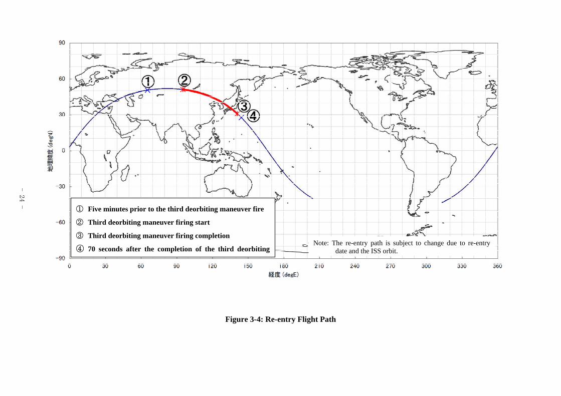
Figure 3-4: Re-entry Flight Path
① Five minutes prior to the third deorbiting maneuver fire
② Third deorbiting maneuver firing start
③ Third deorbiting maneuver firing completion
④ 70 seconds after the completion of the third deorbiting Note: The re-entry path is subject to change due to re-entry
date and the ISS orbit.
- 24 -
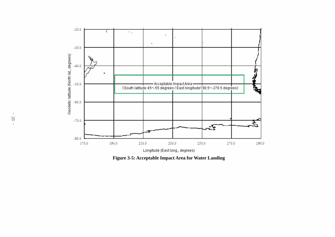
Figure 3-5: Acceptable Impact Area for Water Landing
- 25 -