IW-25-4 Combo Manual 8.5.20
16
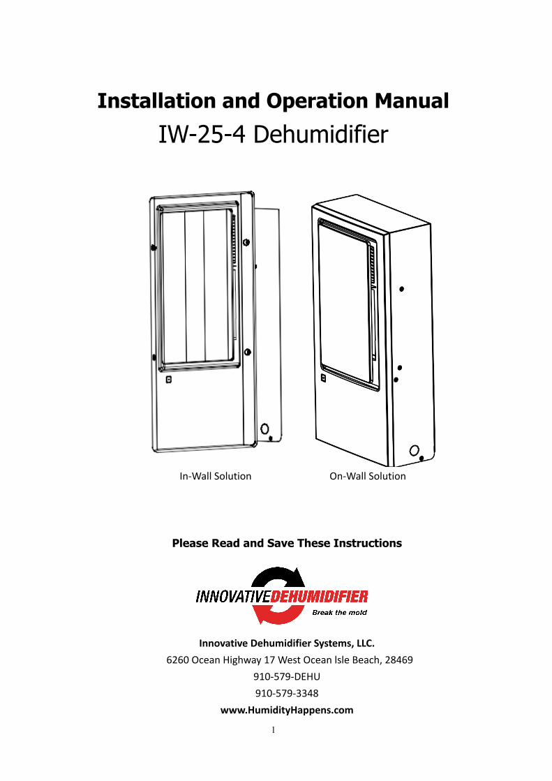
1 Installation and Operation Manual IW-25-4 Dehumidifier In-Wall Solution On-Wall Solution Please Read and Save These Instructions Innovative Dehumidifier Systems, LLC. 6260 Ocean Highway 17 West Ocean lsle Beach, 28469 910-579-DEHU 910-579-3348 www.HumidityHappens.com
Transcript of IW-25-4 Combo Manual 8.5.20
1
Installation and Operation Manual IW-25-4 Dehumidifier
In-Wall Solution On-Wall Solution
Please Read and Save These Instructions
AlorAir Solutions, Inc Innovative Dehumidifier Systems, LLC.
6260 Ocean Highway 17 West Ocean lsle Beach, 28469 910-579-DEHU 910-579-3348
www.HumidityHappens.com

2
Table of Contents Safety Notes................................................................................................................................... 2 Identification................................................................................................................................. . 3 Electrical Supply............................................................................................................................. 3 Principle of Operation.................................................................................................................... 3 Dehumidifier Diagram.................................................................................................................... 4 Dimension Diagram......................................................................................................................... 5 Dehumidifier Installation General 6 In-Wall Solution Only 8 On-Wall Solution Only 9 Optional Condensate Pump Installation 11 Operating Instructions.................................................................................................................... 12 Maintenance................................................................................................................................... 13 Wiring Schematic............................................................................................................................. 14 Troubleshooting............................................................................................................................... 15 Warranty Information...................................................................................................................... 16
Safety Notes
l The IW-25-4 Dehumidifier must always be connected using a grounded electrical connection as
required for all electrical appliances. The warranty is voided and all responsibility for the operation is
born by the owner if non-grounded wiring is utilized.
l The IW-25-4 Dehumidifier must only be installed, maintained and serviced by a qualified technician.
Follow all state and local plumbing and electric codes.
l The IW-25-4 Dehumidifier is intended only for operation when the unit is wall mounted or in wall and
level. Any other orientation could cause water to contact electrical components.
l If any water may have spread throughout the unit, the unit should be opened and allowed to dry
thoroughly before reconnecting to electric and restarting.
l For proper operation, no obstruction should be located within 36” of the discharge of the unit
l Do not insert any objects or fingers into the inlet or discharge. If service is required, call a qualified
technician. All work on unit should be done with the unit “off” and unplugged or the breaker turned
“off.”

3
l Do not use water to clean the unit exterior. Only use a damp cloth to clean the exterior and always
unplug or disconnect the power of unit first.
l The drain hose must be installed to ensure the proper flow of condensate water to a drain source.
Identification:
For future reference, write down the model, serial number, date of purchase so you can identify your unit when seeking assistance in the future. The data label on the side of your unit has key characteristics of your specific unit. Model Number IW-25-4 Serial Number _____________________________ Date of Purchase _____________________________ For additional questions concerning the operation of your dehumidifier, please:
q Contact your installing contractor q Please call Innovative Dehumidifier systems, LLC. Support Team at 910-579-3348
Electrical Supply:
Power Supply: 120 V, 60 Hz AC, Single Phase Outlet Requirement: 3-Prong, GFCI Circuit Protector: 15 Amp Time Delay Fuse or Circuit Breaker
WARNING: 120 Volts AC may cause serious injury from electric shock.
To ensure safety: 1. Disconnect electrical power before servicing 2. Only plug unit into grounded electrical circuit 3. Do not use extension cord 4. Do not use plug adapter
Principle of Operation
The IW-25-4 Dehumidifier utilizes its integral humidistat to monitor the conditioned space. When the relative humidity goes above the selected set point, the dehumidifier will energize. Air is drawn across an evaporator coil, which is cooler than the dew point of air. This means moisture will condense out of the air. The air is then reheated through the condenser coil and distributed back into the room.
4
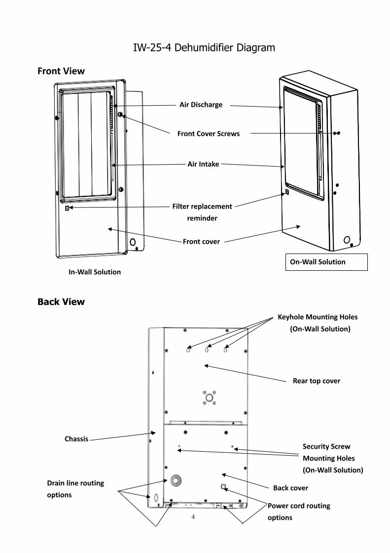
IW-25-4 Dehumidifier Diagram
Front View
+
Back View
Back cover
Air Discharge
Front Cover Screws
Power cord routing options
Chassis
Front cover
Rear top cover
Drain line routing options
Filter replacement reminder
Security Screw Mounting Holes (On-Wall Solution)
Keyhole Mounting Holes (On-Wall Solution)
Air Intake
In-Wall Solution On-Wall Solution
5
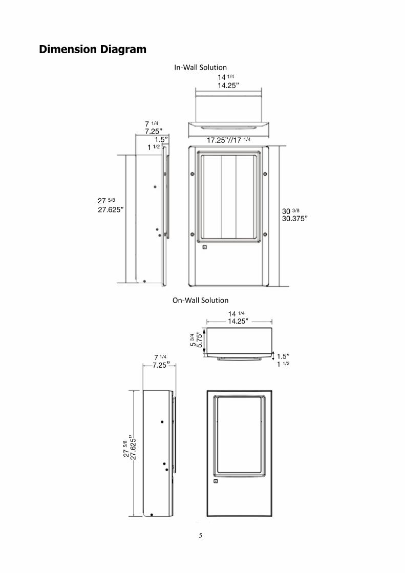
Dimension Diagram In-Wall Solution
On-Wall Solution

6
Dehumidifier Installation Step 1. Cut the two zip ties, and remove the shipping bracket. Fasten mounting tabs (4) with screws provided to the chassis (In-Wall Only) Version 1 Version 2 Step 2. Connect power to unit using either included 10’ power cord or the unit can be hardwired. WARNING! SHUT OFF BREAKER / POWER /Make sure power cord is unplugged BEFORE Wiring Unit. There are two reserved power cord holes, one on the back and one on the bottom of the unit. Remove appropriate knock out as needed. Complete electrical connections: • White to White (L) • Green to Green (GRN) • Black to Black (N)
Attach mounting
tabs to chassis for
in-wall mounting
only
7
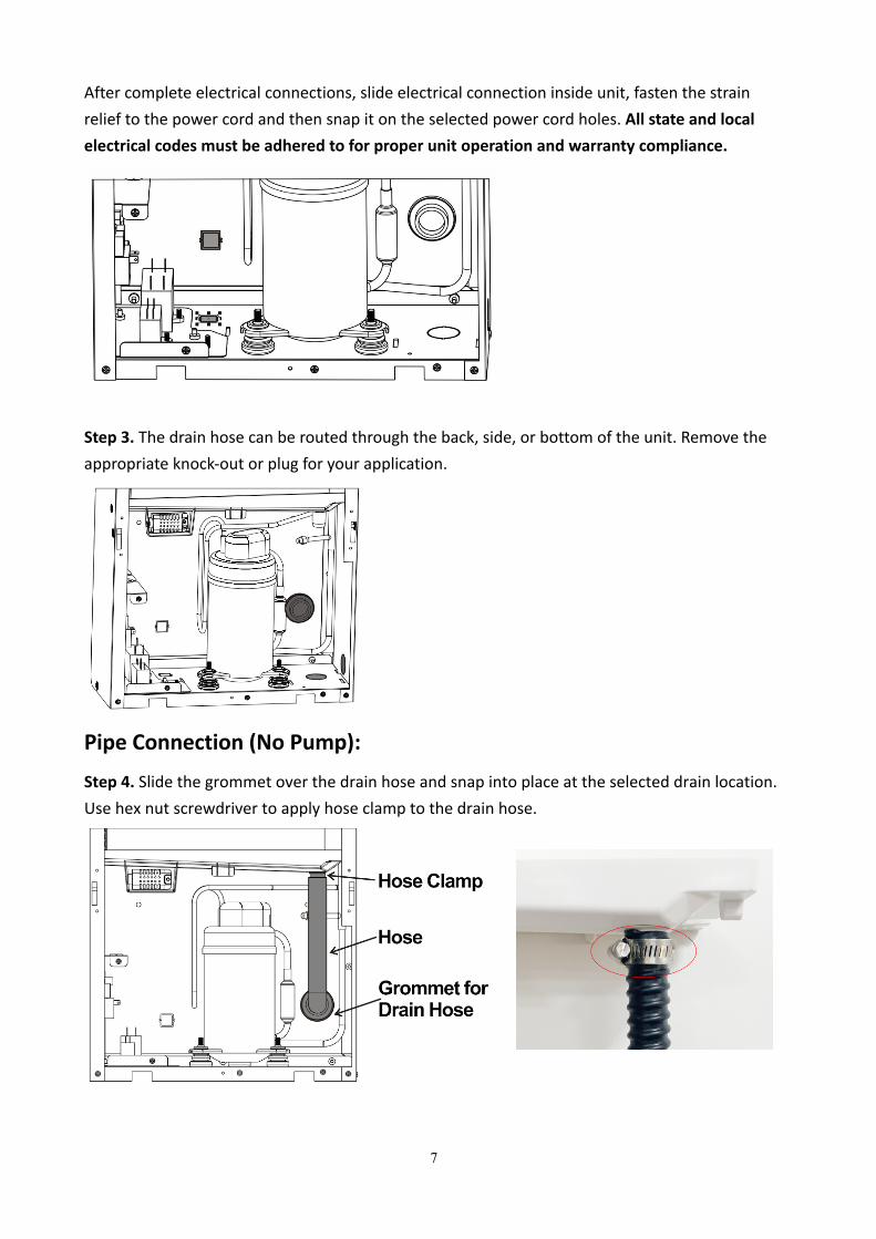
After complete electrical connections, slide electrical connection inside unit, fasten the strain relief to the power cord and then snap it on the selected power cord holes. All state and local electrical codes must be adhered to for proper unit operation and warranty compliance.
Step 3. The drain hose can be routed through the back, side, or bottom of the unit. Remove the appropriate knock-out or plug for your application.
Pipe Connection (No Pump):
Step 4. Slide the grommet over the drain hose and snap into place at the selected drain location. Use hex nut screwdriver to apply hose clamp to the drain hose.

8
IN-WALL ONLY – SEE PAGE 9 for Balance of ON-WALL Installation Instructions NOTE: If mounting unit to drywall, position mounting template so that 1 of the keyhole mounting locations is on a stud. Step 5. Select mounting location between two studs. Step 6. Using the mounting template on the front cover box, mark install location on wall. Step 7. Cut hole. (Rough Opening Dimensions: 28.0” x 14.5” 5.75”) Step 8. Lift the unit and place it near the wall opening to route electrical wires and drain hose through appropriate knockouts. Step 9. Once electrical and drain hose are routed through the unit, set the unit into the wall.
Step 10. The chassis of the units slips in the wall from the front and is secured by the four mounting tabs with screws (not provided). Ensure the unit is level and the bottom of the unit is supported before screwing through the drywall and into the studs. Step 11. Connect the drain line to the drain source making sure to have adequate slope on the drain hose. Step 12. Turn breaker/power back on. Step 13. Set the digital controller to desired RH. See Operating Instructions (Page 12) Step 14. Plug filter light wire from control board into diffuser cover. Step 15. Install diffuser cover by aligning the lower tabs first, then setting the cover back against the wall. Insert the included six tamper-resistant screws to secure the diffuser cover.

9
ON-WALL ONLY (SEE PAGE 8 for IN-WALL Specific Instructions) Step 5: Using the mounting template to locate holes, install 3 screws on the wall (Select appropriate hardware based on application). Leave screw head 3/16” out from the wall surface to allow the unit to be slipped over the screws into the teardrop shaped hanger holes on the rear of the dehumidifier.
Step 6: Hanging the unit on the wall
Position keyhole mounting slots over screws in wall. Ensure center keyhole hits stud. Allow unit to drop onto screws.

10
Step 7: Secure the unit with the 2 safety mounting screws (not supplied).
Step 8. Turn breaker/power back on. Step 9. Set the digital controller to desired RH. See Operating Instructions (Page 12) Step 10. Install diffuser cover by aligning the lower tabs first, then setting the cover back against the wall. Insert the included four tamper-resistant screws (2 tamper-resistant screws on the left and right sides and 2 tamper-resistant screws on the bottom) to secure the diffuser cover.

11
Optional Condensate Pump Installation:
SHUT OFF BREAKER / POWER BEFORE BEGINNING INSTALLATION. 1. Remove the shipping to prepare for installation of pump assembly. 2. Insert included ¾” DIA short drain line into pump reservoir. This drain line will eventually connect to water drain tray. 3. Insert condensate pump into chassis while routing attached drain line and check valve through desired chassis drain hole location (back, bottom, side). 4. Attach pump to chassis with included screw. 5. Connect other end of short ¾” DIA drain line to drain on drain tray just about pump reservoir insuring that other end of ¾” DIA line remains in pump reservoir. 6. Connect power supply line from circuit board to power line from condensate pump 7. Connect float switch line from circuit board to switch line from condensate pump 8. Connect included long condensate line to check valve connected to pump. Route condensate line to desired drain. NOTE: Pump can pump up approximately 10’. After initial vertical rise, condensate line must flow down to drain without any additional loops or vertical rises.

12
Display Board
Operating Instructions 1. ON/OFF Control
Plug the unit in and the display will show the current room relative humidity. Press the on/off button, and the machine will beep twice indicating it is ready for automatic service. If the humidity is below setpoint, it will remain in standby condition. The on/off led will flash indicating the unit is in standby mode. If the humidity is above setpoint, the unit will turn on and begin to remove moisture from the room. The on/off led will be in constant on mode while the dehumidifier is in on mode. Press the on/off button again, and a single beep will indicate that the unit is turning off. No room conditioning will occur until the unit is turned on again. The on/off LED will be turned off.
2. Setting the Humidity Level
Press the button to set indoor humidity. The humidity display will shift from displaying the actual room humidity level to the current setpoint. The humidity can be in 1% increments from 36-90%. Pressing the SET button increases the setpoint by 1% unit you reach 90%, then rolls over to “CO” and increases from there.
Humidity Display
On/Off Button
Humidity Setpoint Button
Filter replacement time switches between 60 or 75 days
LED

13
3. Time
Used to adjust the filter replacement time (selection of 60 days or 75 days).
Maintenance
WARNING: 120 Volts AC may cause serious injury from electric shock. Be sure the unit is
powered off and unplugged or circuit breaker is turned off before removing front cover to service unit.
A. When the filter maintenance red light on the front panel lights up, open the front panel and wash or replace filter as necessary. Light is off during normal operation
B. After the filter replacement is completed, press the filter reminder reset button to reset the filter replacement time.
A. Mix a 6 ounce solution of vinegar (2 oz vinegar + 4 oz water) B. Remove diffuser and filter from face plate so you have access to the drain tray C. Disconnect power to the unit D. Pour the cleaning solution into the drain tray at the base of the coils. If any
cleaning solution gets on the coils, flush with water. E. Allow solution to soak 15 minutes. F. Reconnect unit to power G. Pour in 12 ounces of clean water to flush out the drain line. If optional pump is
installed, it should cycle 2x.
3. Drain Maintenance
2. Filter Maintenance Reminder
1. Unit Maintenance Once a month, complete the following:
A. Clean or change the reusable filter. Reset the filter maintenance light B. Lightly wipe or vacuum the grill, humidity sensor, and coil fins C. Spray the coils with self-rinsing, foaming coil cleaner D. Check the airways and drain hose to make sure they are unblocked

14
Wiring Schematic

15
Troubleshooting

16
Warranty
Innovative Dehumidifier systems, LLC. warrants the equipment to be free from defects in workmanship and materials
for a period of 60 months after shipment. This warranty is limited, however, to the repair or replacement of defective
equipment at the manufacturer’s discretion. This does not apply to optional condensate pump, which has a 1 year
warranty. The optional exterior sleeve is also excluded from the 5 year warranty.
If it is necessary to return unit for service, customer is solely responsible for proper packaging and transportation
costs to and from the service center. Customer must initiate warranty process by contacting IDS. Do not send any
component or product back to IDS without a Return Material Authorization.
This limited warranty does not apply to any part or component that is damaged in transit or when handling, during
installation, has been subject to misuse, has not been installed, operated or serviced according to the Seller’s
instructions, or has been operated beyond the seller’s – rated capacity or has been altered in any way. Routine
maintenance is not covered by this warranty. Lack of proper maintenance voids this warranty.
This warranty does not cover corrosion, freezing or acts of nature – flooding, fire, water damage, power surges, and
hurricane or storm damage.
Seller’s liability is limited to replacement of defective parts or components and does not include any cost of labor
(including, but not limited to, labor to remove and/or reinstall any defective part), refrigerant or piping. Customer
may elect to have unit fixed locally with prior authorization in which case required replacement parts will be sent to
customer at customer’s expense.
IDS shall not be responsible for loss of use of any product, loss of time, inconvenience, or damage to other
equipment, or any other indirect or consequential damage with respect to property whether as a result of breach of
warranty, neglect, or otherwise.
THE WARRANTIES AND LIABILITIES SET FORTH ARE IN LIEU OF ALL OTHER WARRANTIES EXPRESSED OR IMPLIED, IN
LAW OR IN FACT, INCLUDING IMPLIED WARRANTIES OF MERCHANTABILITY AND FITNESS FOR PARTICULAR
PURPOSE. IDS total liability, regardless of nature of claim shall not exceed original purchase price of the product. If
a product or component is replaced while under warranty, the applicable warranty period shall not be extended
beyond the original warranty time period.
The foregoing shall constitute the total liability of seller in the case of defective performance of all or any of the
equipment or services provided to Buyer. Buyer agrees to accept and hereby accepts the foregoing as the sole and
exclusive remedy for any breach or alleged breach of warranty by Seller.