ITEM 3 Propulsion Components and Equipment · Propulsion components and equipment usable in the ......
21
ITEM 3 Propulsion Components and Equipment
-
Upload
phungduong -
Category
Documents
-
view
221 -
download
0
Transcript of ITEM 3 Propulsion Components and Equipment · Propulsion components and equipment usable in the ......

ITEM 3Propulsion Components and Equipment
3-1I T E M 3
Nature and Purpose: The turbojet and turbofan engines of concern are jetengines that can power unmanned air vehicles (UAVs), including cruisemissiles, great distances. They are similar in design and operation to the en-gines that power civilian aircraft, just smaller in size and power. They makelong-range cruise missiles operationally practical.
Method of Operation: The gas turbine engine has several subcomponents, in-cluding the fan (in the case of a turbofan), compressor, combustion chamber,and turbine. The compressor, which may consist of one or more stages of al-ternating stationary and rotating airfoil-section blades, draws air in, pressurizesit, and delivers it into the combustion chamber. The combustion chamber is aheat-resistant tube in which air is mixed with vaporized fuel and then ignited.Spark plugs (called ignitors) initiate combustion, which is continuous once ig-
Produced bycompanies in
•China•France•Germany•India• Israel• Japan•Russia•South Africa•Sweden•United Kingdom•United States
CAT
EGO
RY
II ~
ITE
M 3
PropulsionComponentsandEquipment
Propulsion components and equipment usable in the systems in Item 1,as follows, as well as the specially designed “production facilities” and“production equipment” therefor, and flow-forming machines specifiedin Note (1):(a) Lightweight turbojet and turbofan engines (including turbocom-
pound engines) that are small and fuel efficient;
Notes to Item 3:(2) (a) The only engines covered in subitem (a) above, are the follow-ing:
(1) Engines having both of the following characteristics:(a) Maximum thrust value greater than 1000 N (achieved
un-installed) excluding civil certified engines with amaximum thrust value greater than 8,890 N (achievedun-installed), and
(b) Specific fuel consumption of 0.13kg/N/hr or less (atsea level static and standard conditions); or
(2) Engines designed or modified for systems in Item 1, regard-less of thrust or specific fuel consumption.
(b) Item 3 (a) engines may be exported as part of a manned aircraft orin quantities appropriate for replacement parts for manned aircraft.
3-2 I T E M 3
nition has occurred. The combustion products, or exhaust gases, then pass intothe turbine, which consists of one or more stages of alternating stationary androtating airfoil-section blades. The turbine extracts only enough energy fromthe gas stream to drive the compressor; the remaining energy provides thethrust. The gas flow then passes into a converging duct, or nozzle, in order tomaximize the thrust produced by the engine. In the case of a turbofan, thereis a larger diameter multiblade fan stage in front of the compressor.
Typical Missile-Related Uses: These lightweight engines are used topower UAVs, including cruise missiles.
Other Uses: Such engines are generally not uniquely designed for missilepurposes and can be used directly in other applications such as aircraft andhelicopters. Gas turbine engines are also used in the marine and power-generating industries and in some land vehicles.
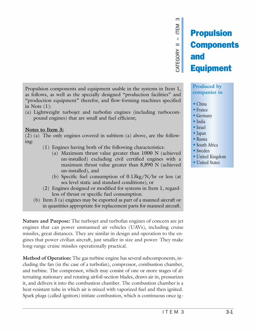
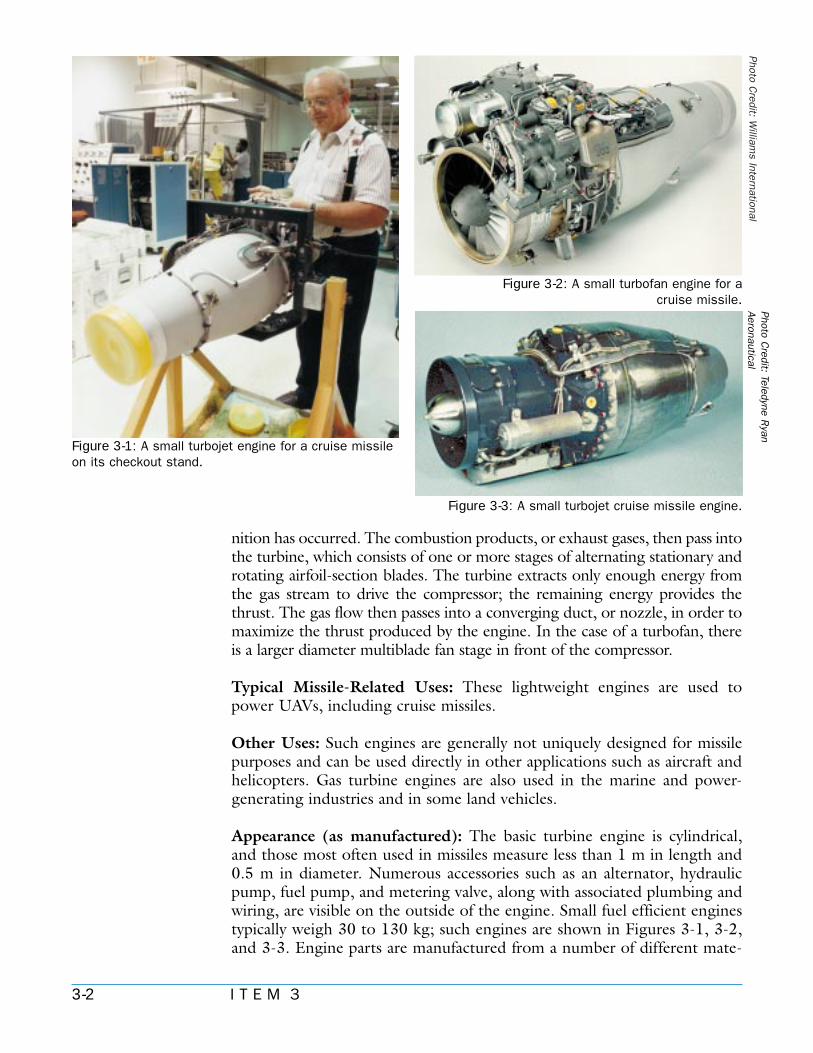
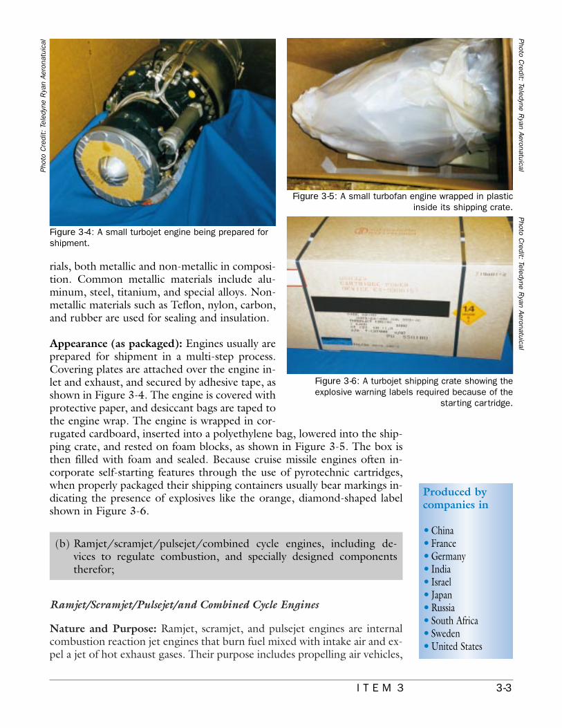
Appearance (as manufactured): The basic turbine engine is cylindrical,and those most often used in missiles measure less than 1 m in length and0.5 m in diameter. Numerous accessories such as an alternator, hydraulicpump, fuel pump, and metering valve, along with associated plumbing andwiring, are visible on the outside of the engine. Small fuel efficient enginestypically weigh 30 to 130 kg; such engines are shown in Figures 3-1, 3-2,and 3-3. Engine parts are manufactured from a number of different mate-
Figure 3-1: A small turbojet engine for a cruise missileon its checkout stand.
Figure 3-2: A small turbofan engine for acruise missile.
Photo Credit: W
illiams International
Figure 3-3: A small turbojet cruise missile engine.
Photo Credit: Teledyne R
yan Aeronautical
3-3I T E M 3
rials, both metallic and non-metallic in composi-tion. Common metallic materials include alu-minum, steel, titanium, and special alloys. Non-metallic materials such as Teflon, nylon, carbon,and rubber are used for sealing and insulation.
Appearance (as packaged): Engines usually areprepared for shipment in a multi-step process.Covering plates are attached over the engine in-let and exhaust, and secured by adhesive tape, asshown in Figure 3-4. The engine is covered withprotective paper, and desiccant bags are taped tothe engine wrap. The engine is wrapped in cor-rugated cardboard, inserted into a polyethylene bag, lowered into the ship-ping crate, and rested on foam blocks, as shown in Figure 3-5. The box isthen filled with foam and sealed. Because cruise missile engines often in-corporate self-starting features through the use of pyrotechnic cartridges,when properly packaged their shipping containers usually bear markings in-dicating the presence of explosives like the orange, diamond-shaped labelshown in Figure 3-6.
Ramjet/Scramjet/Pulsejet/and Combined Cycle Engines
Nature and Purpose: Ramjet, scramjet, and pulsejet engines are internalcombustion reaction jet engines that burn fuel mixed with intake air and ex-pel a jet of hot exhaust gases. Their purpose includes propelling air vehicles,
Produced bycompanies in
•China•France•Germany•India• Israel• Japan•Russia•South Africa•Sweden•United States
(b) Ramjet/scramjet/pulsejet/combined cycle engines, including de-vices to regulate combustion, and specially designed componentstherefor;
Figure 3-5: A small turbofan engine wrapped in plasticinside its shipping crate.
Phot
o C
redi
t: T
eled
yne
Rya
n Ae
rona
tuic
al
Figure 3-4: A small turbojet engine being prepared forshipment.
Photo Credit: Teledyne R
yan Aeronatuical
Figure 3-6: A turbojet shipping crate showing theexplosive warning labels required because of the
starting cartridge.
Photo Credit: Teledyne R
yan Aeronatuical

3-4 I T E M 3
including cruise missiles. Because these engines have very few moving parts(they have no mechanical compressors), they are much simpler and poten-tially less costly than turbojets. Since ramjets and scramjets can toleratemuch higher combustion temperatures than turbojets, they are the onlypractical option for sustained flight at high supersonic speeds. Combinedcycle engines integrate two propulsion systems (e.g., turbojet and ramjet orscramjet) into a single assembly in order to be operable from rest throughsupersonic speeds. A pulsejet is another type of compressorless jet engine;however, unlike ramjets, combustion takes place intermittently (in pulses),and they can produce thrust at rest.
Method of Operation: Ramjets capture air and direct it into the engine asthey move through the atmosphere. The air is compressed by the “ram ef-fect” and slowed to subsonic speeds by diffusion inside the inlet duct. Fuelis added, and the mixture is ignited. Power is produced by the expulsion ofhot exhaust gases through a nozzle. Ramjets usually operate between Mach2 and 3, but can operate over a wide range of speeds from high subsonicMach numbers to supersonic speeds up to about Mach 4. The primary dis-advantage of ramjets is that they cannot generate thrust at zero flight speedso they must be accelerated by some other form of propulsion to the nec-essary starting speed, typically 650 km per hour or higher. A small solid pro-pellant rocket motor is often used at launch for this purpose and discardedafter the ramjet/scramjet is started.
“Scramjet” is a contraction of “supersonic combustion ramjet.” It operateslike the ramjet, but the air entering the engine is not slowed as much andcombustion occurs while the air in the engine is supersonic. Scramjets usu-ally operate at speeds between Mach 5 and 7. Scramjets must be boosted toan appropriate speed (over Mach 4) to permit ignition.
A pulsejet produces thrust by a series of explosions occurring at the ap-proximate resonance frequency of the engine. In one design, air is drawn inthrough open valves at the front of the engine and is heated by the injectedburning fuel. The burning gases expand; as they increase the pressure, theyclose the inlet valves and escape as a jet through the exhaust duct. As theexhaust gases are expelled, the pressure in the combustion chamber de-creases, allowing the front intake valves to open again, than the cycle re-peats. The function of the intake valves is to prevent flow reversal at the in-let. However, the prevention of flow reversal can be accomplished withoutthe use of valves, through the proper use of inlet duct area design and anunderstanding of wave phenomena. By extending the length of the inletduct or by using flow rectifiers (i.e., passages of lesser resistance to the flowin one direction than in the opposite direction), the effects of flow reversalcan be inhibited. Some valveless pulsejet configurations also conserve thrustby turning the intake duct 180 degrees to the freestream (facing aft insteadof forward). Pulsejets typically operate at subsonic speeds.
The turbojet/ramjet combined cycle engine operates as an afterburningturbojet until it reaches a high Mach speed, at which point airflow is by-

3-5I T E M 3
passed around the compressor andinto the afterburner. The enginethen operates as a ramjet with theafterburner acting as the ramjetcombustor.
Typical Missile-Related Uses:These engines can be used to powercruise missiles and sometimes othertypes of UAVs. Ramjet and com-bined cycle engines provide in-creased speed and performance overturbojets with minimum volumeand weight; however, they are notparticularly fuel efficient. Ramjetsproduce substantially more powerper unit volume and typically offermuch greater range and/or payloadcapacity than solid rocket motors.Pulsejets have relatively poorperformance and low fuel ef-ficiency, but they are rela-tively easy to design andmanufacture.
Other Uses: Ramjet andcombined cycle (turbo-ramjet) engines have beenused to power high-speedmanned aircraft and heli-copters.
Appearance (as manufac-tured): Ramjets can be ei-ther mounted in cylindrical pods attached to the mis-sile in various locations or built into the missile body.These engines often resemble a metallic pipe with aconical plug in the inlet to control the air flow and aflared conical nozzle on the opposite end. A typicalramjet for missile use can measure 2 to 4.5 m in lengthand 0.3 to 1.0 m in diameter, and weigh up to 200 kg.An example of a rather large ramjet is shown inFigure 3-7. A scramjet may look like a simple metallicbox with sharp inlets; two developmental scramjets areshown in Figures 3-8 and 3-9. Pulsejets are character-ized by their long cylindrical resonator cavity con-nected to a bulbous control mechanism towards thefront, as shown in Figure 3-10.
Photo Credit: K
aiser Marquardt
Figure 3-7: A large ramjet engine on a handling dolly.
Photo Credit: K
aiser Marquardt
Figure 3-8: A developmental scramjet engine.
Photo Credit: K
aiser Marquardt
Figure 3-9: A developmental scramjet engine.
Figure 3-10: A modern pulsejet engine with arearward-facing intake.
Photo Credit: Therm
o-jet
3-6 I T E M 3
Appearance (as packaged): These engines are packaged like turbojet en-gines covered in (a) above; however, they are most likely to be shipped inwooden or metal crates.
Devices to Regulate Combustion in Ramjets, Scramjets, Pulsejets, andCombined Cycle Engines
Nature and Purpose: Ramjets, scramjets, pulsejets,and combined cycle engines are often required to workover a wide range of velocities, some of which may de-grade engine performance. Devices that regulate com-bustion by altering air- and fuel-flow characteristics inflight are typically integrated into the engine. The es-sential elements of a system to regulate ramjets are flowdividers, fuel-injection systems, ignitors, flameholdingdevices, and a power control computer.
Method of Operation: The control system for a ram-jet engine performs two basic functions: it maintainsthe desired engine performance throughout the flightof the vehicle, and it minimizes departure from thedesired performance during transients.
Typical Missile-Related Uses: Devices that regulatecombustion can make these engines operate efficientlythroughout their flight and thereby increase missilespeed and range. These devices are usually specific tothe engine application and missile configuration forwhich they are designed.
Other Uses: The flow dividers, fuel injection and me-tering devices, and flameholders found in ramjets aresimilar in concept to devices found in afterburningturbojets and turbofans. However, the devices are notinterchangeable.
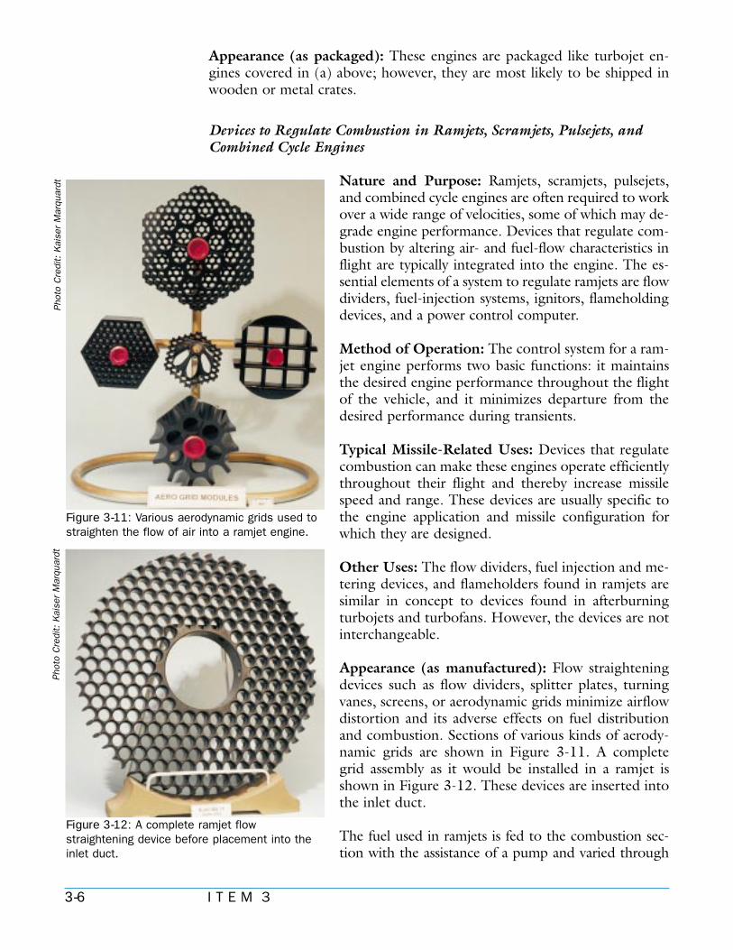
Appearance (as manufactured): Flow straighteningdevices such as flow dividers, splitter plates, turningvanes, screens, or aerodynamic grids minimize airflowdistortion and its adverse effects on fuel distributionand combustion. Sections of various kinds of aerody-namic grids are shown in Figure 3-11. A completegrid assembly as it would be installed in a ramjet isshown in Figure 3-12. These devices are inserted intothe inlet duct.
The fuel used in ramjets is fed to the combustion sec-tion with the assistance of a pump and varied through
Phot
o C
redi
t: K
aise
r M
arqu
ardt
Figure 3-11: Various aerodynamic grids used tostraighten the flow of air into a ramjet engine.
Phot
o C
redi
t: K
aise
r M
arqu
ardt
Figure 3-12: A complete ramjet flowstraightening device before placement into theinlet duct.
3-7I T E M 3
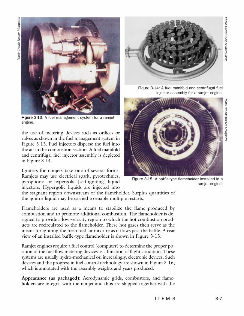
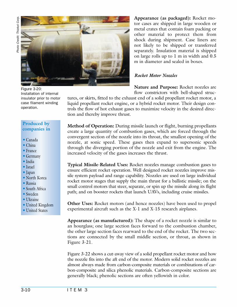
the use of metering devices such as orifices orvalves as shown in the fuel management system inFigure 3-13. Fuel injectors disperse the fuel intothe air in the combustion section. A fuel manifoldand centrifugal fuel injector assembly is depictedin Figure 3-14.
Ignitors for ramjets take one of several forms.Ramjets may use electrical spark, pyrotechnics,pyrophoric, or hypergolic (self-igniting) liquidinjectors. Hypergolic liquids are injected intothe stagnant region downstream of the flameholder. Surplus quantities ofthe ignitor liquid may be carried to enable multiple restarts.
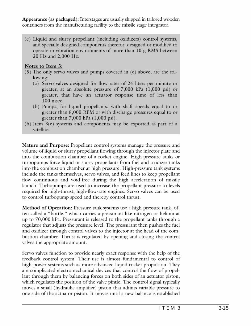
Flameholders are used as a means to stabilize the flame produced bycombustion and to promote additional combustion. The flameholder is de-signed to provide a low-velocity region to which the hot combustion prod-ucts are recirculated to the flameholder. These hot gases then serve as themeans for igniting the fresh fuel-air mixture as it flows past the baffle. A rearview of an installed baffle-type flameholder is shown in Figure 3-15.
Ramjet engines require a fuel control (computer) to determine the proper po-sition of the fuel flow metering devices as a function of flight condition. Thesesystems are usually hydro-mechanical or, increasingly, electronic devices. Suchdevices and the progress in fuel control technology are shown in Figure 3-16,which is annotated with the assembly weights and years produced.
Appearance (as packaged): Aerodynamic grids, combustors, and flame-holders are integral with the ramjet and thus are shipped together with the
Figure 3-13: A fuel management system for a ramjetengine.
Photo Credit: K
aiser Marquardt
Figure 3-14: A fuel manifold and centrifugal fuelinjector assembly for a ramjet engine.
Photo Credit: K
aiser Marquardt
Figure 3-15: A baffle-type flameholder installed in aramjet engine.
Phot
o C
redi
t: K
aise
r M
arqu
ardt

3-8 I T E M 3
main engine. The exceptions are the fuel pumps, igniters, or fuel controls,which may be shipped separately and then mounted on the engine body dur-ing assembly. These parts are shipped in wooden or cardboard containers.
Rocket Motor Cases, Interior Lining, and Insulation
Nature and Purpose: Rocket motor cases are the main structural compo-nents of solid or hybrid rocket motors. Cases are the cylindrical containersof the propellant. They use special materials to resist the pressures and heatof combustion.
Produced bycompanies in
•Brazil•China•France•Germany•India• Israel• Italy• Japan•Norway•Russia•South Korea•Sweden•United Kingdom•United States
(c) Rocket motor cases, “interior lining,” “insulation” and nozzles there-for;
Notes to Item 3:(3) In Item 3(c), “interior lining” suited for the bond interface between
the solid propellant and the case or insulating liner is usually a liquidpolymer based dispersion of refractory or insulating materials, e.g.,carbon filled HTPB or other polymer with added curing agents to besprayed or screeded over a case interior.
(4) In Item 3(c), “insulation” intended to be applied to the componentsof a rocket motor, i.e., the case, nozzle inlets, and case closures, in-cludes cured or semi-cured compounded rubber sheet stock contain-ing an insulating or refractory material. It may also be incorporatedas stress relief boots or flaps.
Phot
o C
redi
t: K
aise
r M
arqu
ardt
Figure 3-16: Ramjet fuelcontrol technology hasprogressed significantlysince the 1960s.

3-9I T E M 3
Method of Operation: Rocket motor cases are pres-sure vessels used to contain the hot gases generatedby the propellant combustion process. These hotgases are expanded and accelerated through therocket motor nozzle to produce thrust. Interior lin-ing and insulation are low-density, high-heat-resis-tant materials that provide protective layers betweenthe burning propellant and the case.
Typical Missile-Related Uses: All solid propellantrocket motors use motor cases and interior lining orinsulation. Such cases are usually designed to meetspecific requirements of particular missiles. Cases, in-terior lining, and insulation are critical to maintainthe integrity of solid rocket motors.
Other Uses: Motor case materials are used in high-pressure applications such as piping. Some materialsused in the interior linings or insulation of rocket mo-tors are used in commercial applications requiringheat-resistant materials.
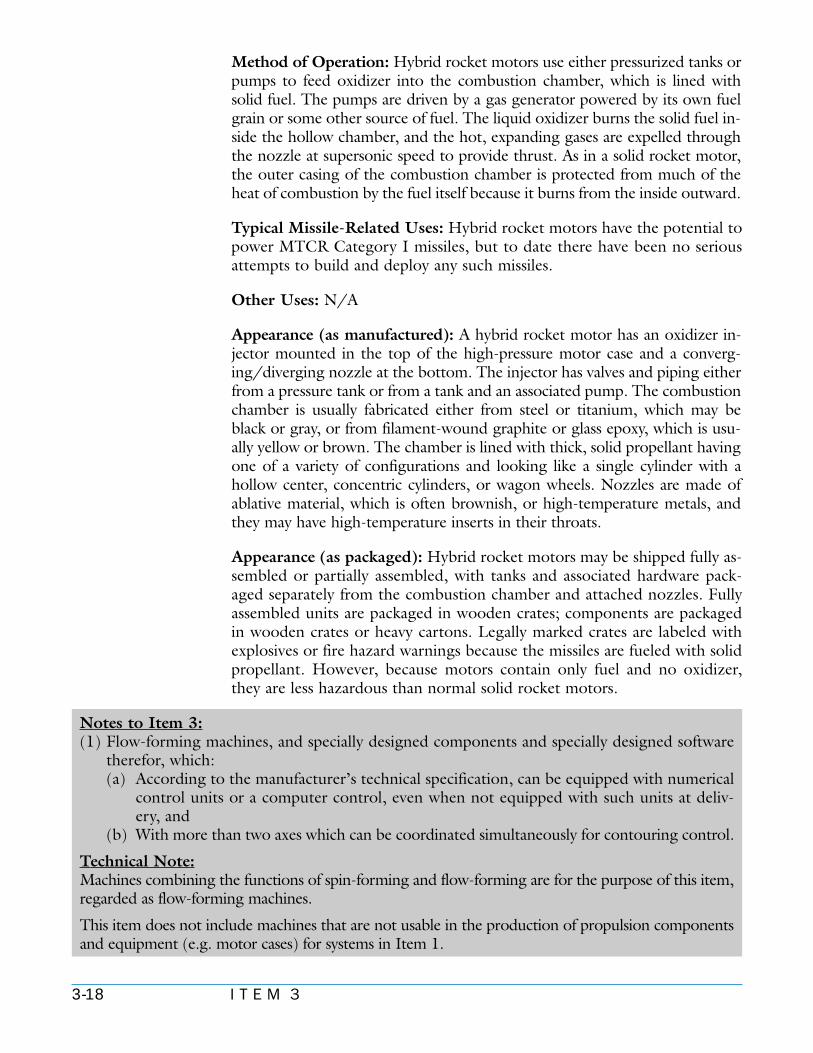
Appearance (as manufactured): A rocket motor caseis a large, steel or composite-filament-wound cylinderwith spheroidal or ellipsoidal domes at either end. Amotor case for an Item 2(c) rocket motor typicallywould be larger than 4 m in length and 0.5 m in diam-eter. Each of the domes usually has a hole; the smallhole at the front end is for the igniter or other internalmotor hardware, and the large hole at the back end isfor the nozzle. A large filament-wound mo-tor case displaying these features is shownin Figure 3-17. An interior lining is a thinlayer of special chemicals used to help thesolid propellant adhere to the case insula-tion. The lining is usually applied to thecase onsite before propellant casting. Thecase may or may not have internal insula-tion in place when shipped. Rocket motorinsulation is usually made of synthetic rub-bery material such as ethylene propylenediene monomer, (EPDM), polybutadiene,neoprene, or nitrile rubber. Insulationmaterial contains silica or asbestos and re-sembles a gray or green sheet of rubber approximately 2 to 6 mm thick.Figure 3-18 shows installation of lining inside a motor case. Figure 3-19 showsa motor case under inspection after application of the thermal insulation.Figure 3-20 shows the installation of the internal insulation onto a mandrelprior to the motor case filament winding operation.
Photo Credit: Aerospatiale
Espace & D
efense
Figure 3-17: A large filament-wound solid rocketmotor case.
Photo Credit: Thiokol C
orp.
Figure 3-18: Installation of lining inside amotor case.
Photo Credit: Fiat Avio
Figure 3-19: A rocket case under inspection after applicationof the thermal insulation.
3-10 I T E M 3
Appearance (as packaged): Rocket mo-tor cases are shipped in large wooden ormetal crates that contain foam packing orother material to protect them fromshock during shipment. Case liners arenot likely to be shipped or transferredseparately. Insulation material is shippedon large rolls up to 1 m in width and 0.5m in diameter and sealed in boxes.
Rocket Motor Nozzles
Nature and Purpose: Rocket nozzles areflow constrictors with bell-shaped struc-
tures, or skirts, fitted to the exhaust end of a solid propellant rocket motor, aliquid propellant rocket engine, or a hybrid rocket motor. Their design con-trols the flow of hot exhaust gases to maximize velocity in the desired direc-tion and thereby improve thrust.
Method of Operation: During missile launch or flight, burning propellantscreate a large quantity of combustion gases, which are forced through theconvergent section of the nozzle into its throat, the smallest opening of thenozzle, at sonic speed. These gases then expand to supersonic speedsthrough the diverging portion of the nozzle and exit from the engine. Theincreased velocity of the gases increases the thrust.
Typical Missile-Related Uses: Rocket nozzles manage combustion gases toensure efficient rocket operation. Well designed rocket nozzles improve mis-sile system payload and range capability. Nozzles are used on large individualrocket motor stages that supply the main thrust for a ballistic missile; on thesmall control motors that steer, separate, or spin up the missile along its flightpath; and on booster rockets that launch UAVs, including cruise missiles.
Other Uses: Rocket motors (and hence nozzles) have been used to propelexperimental aircraft such as the X-1 and X-15 research airplanes.
Appearance (as manufactured): The shape of a rocket nozzle is similar toan hourglass; one large section faces forward to the combustion chamber,the other large section faces rearward to the end of the rocket. The two sec-tions are connected by the small middle section, or throat, as shown inFigure 3-21.
Figure 3-22 shows a cut-away view of a solid propellant rocket motor and howthe nozzle fits into the aft end of the motor. Modern solid rocket nozzles arealmost always made from carbon-composite materials or combinations of car-bon-composite and silica phenolic materials. Carbon-composite sections aregenerally black; phenolic sections are often yellowish in color.
Produced bycompanies in
•Canada•China•France•Germany•India• Israel• Japan•North Korea•Russia•South Africa•Sweden•Ukraine•United Kingdom•United States
Figure 3-20:Installation of internalinsulator prior to motorcase filament windingoperation.
Phot
o C
redi
t: T
hiok
ol C
orp.

3-11I T E M 3
Liquid propellantrockets may usecarbon-compositenozzles, but usuallyuse metal-based ma-
terials such as stainless steel alloys or titanium andcolumbium (niobium). Metal nozzles are one ofseveral shades of gray as shown in Figure 3-21.Nozzles also may have a metal exterior and a non-metallic interior made of materials that can with-stand the high temperature of the exhaust gases,such as bulk graphite or silica phenolic.
Nozzle size depends on the rocket size and appli-cation. Large nozzles intended for solid propellantrocket motors are increasingly built as movablenozzles. In such an application, the forward end ofthe nozzle has devices and insulators that allow itto be attached to the aft dome of the motor in a ball-in-socket arrangement. These nozzles may have 2 to 4 lugs onthe outside wall to which the motion actuators are fastened,or the actuators may be connected near the throat. Very ad-vanced nozzles can be extendable, which means they arestored in a collapsed configuration and extended to their fulldimensions when needed. Such a nozzle complete with itsactuators and control mechanism is shown in Figure 3-23.Nozzles intended for liquid rocket engines usually are re-generatively cooled. They are made either by a series ofmetal tubes welded together to form the nozzle, or by sand-wiching a piece of corrugated metal between an inner andouter wall, as shown in Figures 3-24, 3-25, and 3-26. Fuelis injected into the large manifold near the bottom of the
Phot
o C
redi
t: A
eroj
et-G
ener
al C
orp.
Figure 3-21: A liquid enginewith a metal, radiatively cooledlower nozzle skirt.
Photo Credit:Thiokol Corp.
Figure 3-22:A cut-away view of asolid motor thatshows how thenozzle fits into theaft end of the motor.
Photo Credit: Alliant TechS
ystems, Inc.
Figure 3-23: A modern
extendable rocketnozzle skirtshowing the
actuators thatincrease its length
after staging.
Photo Credit: AlliedS
ignal/Aerospace
Figure 3-24:An engine with a large,regeneratively coolednozzle.
Photo Credit: B
oeing
Figure 3-25: Side view of a regenerativelycooled nozzle.

3-12 I T E M 3
nozzle; as it flows up through the passages it ab-sorbs heat and cools the nozzle.
Appearance (as packaged): Shipping contain-ers for rocket nozzles are of two types, depend-ing on nozzle size. Small nozzles with an exitdiameter no greater than 50 cm have tailoredcontainers, even metallic cases. Larger nozzlesusually have tailored shipping containers builtfrom wood or fiberglass. Protective plastic wrapsmay also be used, depending on the envi-ronmental-control capability of the shippingcontainer.
Staging Mechanisms and Separation Mechanisms
Nature and Purpose: Separating rocket stages quickly and cleanly is tech-nically challenging. Moreover, it is critical to the successful flight of a multi-stage missile. Staging mechanisms ensure the safe and reliable separation oftwo missile stages after termination of the thrust of the lower stage. Thisseparation is achieved by relatively simple separation mechanisms, the mostcommon of which are explosive bolts and flexible linear shaped charges(FLSC). Explosive bolts attach the missile stages together through speciallyconstructed, load-carrying interstages with flanges at the ends and, onsignal, explode to allow the two stages to separate. A built-in FLSC is usedto make a circumferential cut through the interstage skin and structure toallow stage separation. Mechanical, hydraulic, or pneumatic devices can beused to help separate stages. Similarly, mechanisms like ball locks are usedfor separating the payload from the uppermost missile stage at the very endof powered flight.
Method of Operation: When the propellant in any missile stage is nearlyexhausted, the guidance set signals the separation hardware to release thespent stage. This electronic signal fires detonators which, in turn, triggerseparation mechanisms like explosive bolts or FLSC that sever the structuraland electrical connection and let the exhausted missile stage drop off. If at-mospheric drag forces are not likely to be strong enough to ensure separa-tion, mechanical, hydraulic, or pneumatic compression springs are placedbetween the two stages to force them apart. Spent stages may require re-verse thrusters or thrust termination to prevent collision of the stages priorto next-stage ignition.
Typical Missile-Related Uses: All multi-stage missiles require staging andseparation mechanisms. Single-stage missiles with separating warheads alsorequire separation mechanisms.
Phot
o C
redi
t: B
oein
g
Figure 3-26:End views ofregenerativelycooled nozzles.
Produced bycompanies in
•China•France•Germany•India• Israel• Italy• Japan•North Korea•Russia•United Kingdom•United States
(d) Staging mechanisms, separation mechanisms, and interstages therefor;

3-13I T E M 3
Other Uses: Prepackaged devices such as ex-plosive bolts have other military applications,most notably in launching weapons or sepa-rating external fuel tanks from fighter aircraft.FLSC are routinely used in the oil industry forcutting large pipes. Compression springs areused in the industrial world as shock absorbersand load-levelers.
Appearance (as manufactured): Explosivebolts look like large machine bolts, but with ahousing section at the head end; three exam-ples are shown in Figure 3-27. Typically, theymeasure 7 to 10 cm in length and 1 to 2.5 cmin diameter, and weigh 50 to 75 g. The hous-ing section contains the ordnance and haswires or cables leading out of it from the in-ternal detonators, which typically require aDC power source. Built-in staging mechanisms almost always use FLSC, achevron-shaped, soft metal tube of lead or aluminum filled with explosive, typ-ically RDX or HMX. The FLSC is fastened by metal clips to the interior of theinterstage structure holding the two missile stages together and, when initiatedby a small detonator, cuts through the structure and skin to release the stages.The tube is a gray metal color, and the explosive is white to whitish-gray incolor, as shown in Figure 3-28. The width, height, andweight per unit of length are a function of the thicknessof the material it is designed to cut through.
Ball locks do not involve explosives and are sometimesused in payload separation systems. Internally, they use asolenoid/spring/ball-bearing that enables the desiredsoft disconnect; externally, they appear much like explo-sive bolts, that is, like a machine bolt with a housing andtwo wires. Compression springs used for stage separationare long stroke (10 to 20 cm), small diameter (2 to 4 cm)devices mounted in canisters at several locations (mini-mum of three) in the rim of the interstage. These steelcanisters house steel springs or pistons and have built-in flanges for attachmentto the interstage. The hydraulic and pneumatic pistons have built-in fluid reser-voirs to pressurize the units when the stages are assembled.
Appearance (as packaged): Explosive bolts are shipped in simple cardboardboxes with ample internal foam or other packing to mitigate the effects ofshocks. Properly shipped boxes are marked with “Danger-Explosive” or“Danger-Ordnance” symbols and are shipped under restrictions governingexplosive materials. FLSC are usually shipped in varying lengths in lined andprotected wooden boxes. They are supposed to be marked with the same la-bels as they are subject to the same shipping restrictions as any ordnance. Balllocks can be packaged and shipped without ordnance restrictions and have
Photo Credit: H
i-Shear Technology C
orp.
Figure 3-27: Threeexamples of explosive
bolts. Notice theelectrical connection
on the top bolt, whichdetonates it.
Photo Credit: Ensign-B
ickford Co.
Figure 3-28: Shortsection of flexible
linear-shaped charge(on a centimeter
scale) designed tocut through a missile
stage.

3-14 I T E M 3
no distinguishing features or labels on their packaging. Compression springsare shipped in the uncompressed state in cardboard boxes.
Interstages
Nature and Purpose: An interstage is a cylindrical or truncated-cone-shapedstructure that connects two missile propulsion stages. An interstage is, in prin-ciple, a simple piece of equipment, but the requisite electrical connections, sep-aration mechanisms, and high strength-to-weight ratios make it rather complexin its adaptation to specific missiles. The purpose of an interstage is to maintainmissile integrity during launch and flight, and to ensure stage separation with-out damage to any missile component or adverse effect on velocity.
Method of Operation: Upon command from the guidance system, the sep-aration mechanism is prompted, first, to release the lower stage from the in-terstage connecting it to the next stage, and secondly, after a brief pause, tojettison that interstage. In some cases, separation occurs between theinterstage and the upper stage; the interstage remains attached to the lowerstage. Staging mechanisms are usually activated before the upper stage ignites.
Typical Missile-Related Uses: Interstages are used to carry thrust loads fromthe lower stage to the upper stages of ballistic missiles during rocket motor
burn. Some early designs used simple open-truss struc-tures; later designs incorporate thin-skin shell coveringsto reduce drag by creating a smooth aerodynamic fairingbetween the stages. They also incorporate the separationmechanisms used to jettison the spent lower stage.Dropping a spent lower stage improves missile range(compared to that of a single stage missile) but must beaccomplished cleanly and with proper timing to preventdamage to the missile or deviation from its trajectory.
Other Uses: N/A
Appearance (as manufactured): An interstage is aconical or cylindrical hoop-like structure that has thesame outside diameter as the rocket stages it connects.It has connecting frames at each end and locations forseparation devices on one end. It has structural sup-ports visible inside the structural walls and end rings orframes used to join it to the missile stages. The lengthof an interstage is usually equal to about half the out-side diameter of the engine nozzle on the next stageabove. In the past stainless steel and titanium have beenused, but current interstages use graphite compositeconstruction with metal end rings. Two interstages in ashipping crate are shown in Figure 3-29. An interstagebeing positioned for attachment to a solid rocket mo-tor is shown in Figure 3-30.
Produced bycompanies in
•Brazil•China•France•Germany•India• Israel• Italy• Japan•North Korea•Norway•Pakistan•Russia•South Korea•Spain•Sweden•Ukraine•United Kingdom•United States
Figure 3-29: Two interstages in their shippingcontainer.
Figure 3-30: An interstage being positioned forattachment.
3-15I T E M 3
Appearance (as packaged): Interstages are usually shipped in tailored woodencontainers from the manufacturing facility to the missile stage integrator.
Nature and Purpose: Propellant control systems manage the pressure andvolume of liquid or slurry propellant flowing through the injector plate andinto the combustion chamber of a rocket engine. High-pressure tanks orturbopumps force liquid or slurry propellants from fuel and oxidizer tanksinto the combustion chamber at high pressure. High-pressure tank systemsinclude the tanks themselves, servo valves, and feed lines to keep propellantflow continuous and void-free during the high acceleration of missilelaunch. Turbopumps are used to increase the propellant pressure to levelsrequired for high-thrust, high-flow-rate engines. Servo valves can be usedto control turbopump speed and thereby control thrust.
Method of Operation: Pressure tank systems use a high-pressure tank, of-ten called a “bottle,” which carries a pressurant like nitrogen or helium atup to 70,000 kPa. Pressurant is released to the propellant tanks through aregulator that adjusts the pressure level. The pressurant then pushes the fueland oxidizer through control valves to the injector at the head of the com-bustion chamber. Thrust is regulated by opening and closing the controlvalves the appropriate amount.
Servo valves function to provide nearly exact response with the help of thefeedback control system. Their use is almost fundamental to control ofhigh-power systems such as more advanced liquid rocket propulsion. Theyare complicated electromechanical devices that control the flow of propel-lant through them by balancing forces on both sides of an actuator piston,which regulates the position of the valve pintle. The control signal typicallymoves a small (hydraulic amplifier) piston that admits variable pressure toone side of the actuator piston. It moves until a new balance is established
(e) Liquid and slurry propellant (including oxidizers) control systems,and specially designed components therefor, designed or modified tooperate in vibration environments of more than 10 g RMS between20 Hz and 2,000 Hz.
Notes to Item 3:(5) The only servo valves and pumps covered in (e) above, are the fol-
lowing:(a) Servo valves designed for flow rates of 24 liters per minute or
greater, at an absolute pressure of 7,000 kPa (1,000 psi) orgreater, that have an actuator response time of less than100 msec.
(b) Pumps, for liquid propellants, with shaft speeds equal to orgreater than 8,000 RPM or with discharge pressures equal to orgreater than 7,000 kPa (1,000 psi).
(6) Item 3(e) systems and components may be exported as part of asatellite.

3-16 I T E M 3
at a new flow rate. Servo valves are usually the mostcostly, sensitive, and failure-prone of all valvesbecause their orifices can easily be clogged bycontaminants.
Turbopumps push propellants into the combustionchamber at pressures up to fifty times greater than thepressure at which the propellants normally are stored.Turbopumps are powered by burning some of therocket propellant in a gas generator; its exhaust gasespower a turbine driving the pump. Turbopumps formissiles typically rotate at 8,000 to 75,000 RPM.Engine thrust is regulated by altering the propellant
flow to the gas generator (sometimes with a servo valve), and therebychanging the turbine speed of the turbopump and thus the propellant flowinto the combustion chamber.
Typical Missile-Related Uses: All liquid propellant rocketengines use either a pressure-fed or a pump-fed propellantdelivery system. Pressure-fed systems can be specifically de-signed for a particular engine or assembled from dual-usecomponents. Turbopumps are usually specifically designedfor a particular engine.
Other Uses: Servo valves are common in closed-loop con-trol systems handling liquids. Numerous civil applications in-clude fuel and hydraulic system control in aircraft. Other ap-
plications involve precision handling of fluids such as in the chemical industry.Turbine drill pumps are popular in the petroleum and deep well industries.
Appearance (as manufactured): Servo valves look much like on-off valvesor line cylinders with tube stubs for propellant inlets and outlets in a metalcase. Most valves and housings are made of stainless steel. However, thesevalves are larger than on-off valves because they have a position feedback de-vice. A servo valve from a Scud missile is shown in Figure 3-31. A modernliquid propellant control valve is shown in Figure 3-32. Two types of liquidpropellant injector plates are shown in Figures 3-33 and 3-34.
Figure 3-31: A servo valve from a Scud missile.
Figure 3-32:A modern liquidpropellantcontrol valve.
Figure 3-33:A liquid propellantinjector plate.
Photo Credit: AlliedSignal Aerospace
Figure 3-34:Another style ofliquid propellantinjector plate.
Phot
o C
redi
t: B
oein
gPh
oto
Cre
dit:
Boe
ing

3-17I T E M 3
Turbopumps are usually housedin metal cases and are sized forspecific applications. Althoughthey resemble automotive ortruck turbochargers, they aremuch larger and can weigh sev-eral hundred kilograms. Turbo-pumps for rocket engines mayhave a separate pump and tur-bine assembly for each propel-lant (e.g., for the fuel and forthe oxidizer), or a single unitthat combines both pumps andthe turbine drive mechanism.Examples of single- and multi-shaft turbopump assemblies areshown in Figures 3-35 and 3-36, respectively. The ribbing ofthe housings is typical of tur-bopumps because they providegood strength and light weight;however, some turbopumpshave smooth metallic housings,as shown in Figure 3-37.
Appearance (as packaged): Servo valves are packaged likeother valves, especially on-off valves. Inlets and outlets areplugged to prevent contamination. The valves are placed invacuum-sealed plastic bags or sealed plastic bags filled withnitrogen or argon to keep the valves clean and dry. They maysometimes be double bagged and are usually shipped inside acontainer, often an aluminum case with a contoured foamliner. Small turbopumps are often packaged and shipped in alu-minum shipping containers. Depending on size and interfacefeatures, a large turbopump may be packaged and shipped in acustom-built shipping crate, with pump supports built in.Turbopumps may also be shipped as a breakdown kit in whichseparate components are packaged for assembly after receipt.
Nature and Purpose: Hybrid rocket motors use both solid and liquid propel-lants, usually a solid fuel and a liquid oxidizer. Because flow of the liquid oxi-dizer can be controlled, hybrid motors can be throttled or shut down com-pletely and then restarted. Hybrid rocket motors thereby combine some of thesimplicity of solid rocket motors with the controllability of liquid rocket engines.
Figure 3-36: A multi-shaft turbopumpassembly.
Figure 3-37: A smooth turbopumphousing; compare with those in
Figures 3-35 and 3-36.
Figure 3-35: A single-shaftturbopump.
Photo Credit: AerojetPh
oto
Cre
dit:
Aer
ojet
Photo Credit: AlliedS
ignal Aerospace
(f) Hybrid rocket motors and specially designed components therefor.
Produced bycompanies in
•Japan•Russia•United States
3-18 I T E M 3
Method of Operation: Hybrid rocket motors use either pressurized tanks orpumps to feed oxidizer into the combustion chamber, which is lined withsolid fuel. The pumps are driven by a gas generator powered by its own fuelgrain or some other source of fuel. The liquid oxidizer burns the solid fuel in-side the hollow chamber, and the hot, expanding gases are expelled throughthe nozzle at supersonic speed to provide thrust. As in a solid rocket motor,the outer casing of the combustion chamber is protected from much of theheat of combustion by the fuel itself because it burns from the inside outward.
Typical Missile-Related Uses: Hybrid rocket motors have the potential topower MTCR Category I missiles, but to date there have been no seriousattempts to build and deploy any such missiles.
Other Uses: N/A
Appearance (as manufactured): A hybrid rocket motor has an oxidizer in-jector mounted in the top of the high-pressure motor case and a converg-ing/diverging nozzle at the bottom. The injector has valves and piping eitherfrom a pressure tank or from a tank and an associated pump. The combustionchamber is usually fabricated either from steel or titanium, which may beblack or gray, or from filament-wound graphite or glass epoxy, which is usu-ally yellow or brown. The chamber is lined with thick, solid propellant havingone of a variety of configurations and looking like a single cylinder with ahollow center, concentric cylinders, or wagon wheels. Nozzles are made ofablative material, which is often brownish, or high-temperature metals, andthey may have high-temperature inserts in their throats.
Appearance (as packaged): Hybrid rocket motors may be shipped fully as-sembled or partially assembled, with tanks and associated hardware pack-aged separately from the combustion chamber and attached nozzles. Fullyassembled units are packaged in wooden crates; components are packagedin wooden crates or heavy cartons. Legally marked crates are labeled withexplosives or fire hazard warnings because the missiles are fueled with solidpropellant. However, because motors contain only fuel and no oxidizer,they are less hazardous than normal solid rocket motors.
Notes to Item 3:(1) Flow-forming machines, and specially designed components and specially designed software
therefor, which: (a) According to the manufacturer’s technical specification, can be equipped with numerical
control units or a computer control, even when not equipped with such units at deliv-ery, and
(b) With more than two axes which can be coordinated simultaneously for contouring control.
Technical Note:Machines combining the functions of spin-forming and flow-forming are for the purpose of this item,regarded as flow-forming machines.
This item does not include machines that are not usable in the production of propulsion componentsand equipment (e.g. motor cases) for systems in Item 1.
3-19I T E M 3
Nature and Purpose: Flow-forming machines are large shop machines usedin heavy duty manufacturing to make parts to precision dimensions. Theirbases are massive in order to support the structures for mounting rollers, man-drels, and other components. Power supplies, hydraulic rams, and positioningscrews are also large enough to resist deflection by the large forming forces.
Method of Operation: Flow-forming machines use a point-deformationprocess whereby one or more rollers move along the length of a metalblank, or preform, and press it into a rotating mold or onto a mandrel withthe desired shape.
Typical Missile-Related Uses: Flow-forming machines are used to makerocket motor cases, end domes, and nozzles.
Other Uses: Flow-forming machines are used to make numerous parts for theaerospace industry, including commercial aircraft parts, tactical missile compo-nents, and liners for shaped charges. They are also used to make automobilewheels, automatic transmission components for automobiles, gas containers,pressure-tank heads, and containers for electronic equipment.
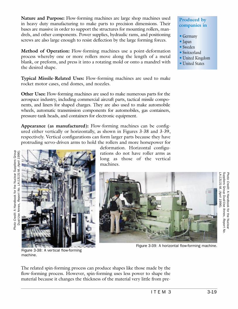
Appearance (as manufactured): Flow-forming machines can be config-ured either vertically or horizontally, as shown in Figures 3-38 and 3-39,respectively. Vertical configurations can form larger parts because they haveprotruding servo-driven arms to hold the rollers and more horsepower for
deformation. Horizontal configu-rations do not have roller arms aslong as those of the verticalmachines.
The related spin-forming process can produce shapes like those made by theflow-forming process. However, spin-forming uses less power to shape thematerial because it changes the thickness of the material very little from pre-
Produced bycompanies in
•Germany•Japan•Sweden•Switzerland•United Kingdom•United States
Figure 3-38: A vertical flow-formingmachine.
Figure 3-39: A horizontal flow-forming machine.
Phot
o C
redi
t: A
Han
dboo
k fo
r th
e N
ucle
ar S
uppl
iers
Gro
upD
ual-U
se A
nnex
, R
epor
t N
o. L
A-13131-M
, (A
pril
1996).
Photo Credit: A H
andbook for the Nuclear
Suppliers G
roup Dual-U
se Annex, Report N
o.LA-1
3131-M
, (April 19
96
).

3-20 I T E M 3
form to final shape. An exampleof a flow-forming machine usedto make end domes for propellanttanks is shown in Figure 3-40.
Specially designed productionfacilities and equipment resembleaerospace and manufacturingequipment but with attributesdesigned for a given system.
Appearance (as packaged):Larger vertical machines usuallyrequire that roller areas, verticalcolumns, and mandrels be boxedseparately in wooden crates forshipping. Smaller vertical ma-chines as well as horizontal ma-chines may be shipped in largewooden containers, with theroller arms shipped in the assem-
bled configuration. They are securely fastened to the containers to precludemovement. The control unit and any hydraulic supply and power units arealso boxed separately for shipment.
Figure 3-40: A flow-formingmachine used tomake end domes forpropellant tanks.
Phot
o C
redi
t: A
eroj
et