Components redundancy in power and propulsion systems installed onboard platform supply vessels
13
Components redundancy Components redundancy in power and propulsion systems in power and propulsion systems installed onboard platform supply vessels installed onboard platform supply vessels RISK, QUALITY AND RELIABILITY – RQR ‘07 September 20-21, 2007 Technical University of Ostrava, Czech Republic Dr inż. Leszek Chybowski Prof. dr hab. inż. Zbigniew Matuszak Mgr inż. Paweł Pełka
-
Upload
erasmus-hutchinson -
Category
Documents
-
view
20 -
download
0
description
RISK, QUALITY AND RELIABILITY – RQR ‘07 September 20-21, 2007 Technical University of Ostrava, Czech Republic. Components redundancy in power and propulsion systems installed onboard platform supply vessels. Dr inż. Leszek Chybowski Prof. dr hab. inż. Zbigniew Matuszak. - PowerPoint PPT Presentation
Transcript of Components redundancy in power and propulsion systems installed onboard platform supply vessels

Components redundancy Components redundancy in power and propulsion systems in power and propulsion systems installed onboard platform supply vesselsinstalled onboard platform supply vessels
RISK, QUALITY AND RELIABILITY – RQR ‘07September 20-21, 2007
Technical University of Ostrava, Czech Republic
Dr inż. Leszek Chybowski
Prof. dr hab. inż. Zbigniew Matuszak
Mgr inż. Paweł Pełka

Minutes of presentationMinutes of presentation
Dynamic positioning (DP) systems classification
Platform supply vessels characteristics
Power and propulsion plants characteristics
Propulsion and power plants components redundancy
Final conclusion
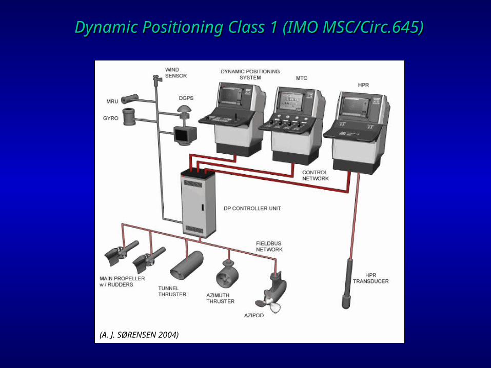
Dynamic Positioning Class 1 Dynamic Positioning Class 1 ((IMO MSC/Circ.645IMO MSC/Circ.645))
(A. J. SØRENSEN 2004)

Dynamic Positioning Class Dynamic Positioning Class 22 ((IMO MSC/Circ.645IMO MSC/Circ.645))
(A. J. SØRENSEN 2004)
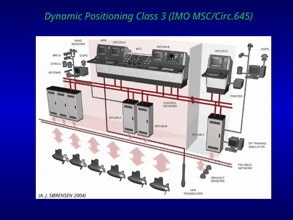
Dynamic Positioning Class Dynamic Positioning Class 33 ((IMO MSC/Circ.645IMO MSC/Circ.645))
(A. J. SØRENSEN 2004)
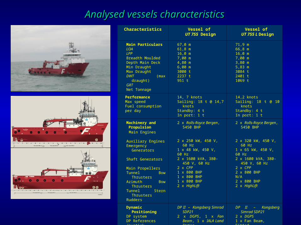
Characteristics Vessel of UT 755 Design
Vessel of UT 755 L Design
Main ParticularsLOALPPBreadth MouldedDepth Main DeckMin DraughtMax DraughtDWT (max draught)GRTNet Tonnage
67,0 m61,8 m16,0 m7,00 m4,80 m6,00 m3000 t2237 t951 t
71,9 m66,8 m16,0 m7,00 m3,80 m5,83 m3084 t2401 t1069 t
PerformanceMax speedFuel consumption per day
14, 7 knotsSailing: 18 t @ 14,7 knotsStandby: 4 tIn port: 1 t
14,2 knotsSailing: 18 t @ 10 knotsStandby: 4 tIn port: 1 t
Machinery and Propulsion Main Engines
Auxiliary EnginesEmergency
Generators
Shaft Generators
Main PropellersTunnel Bow ThrustersAzimuth Bow
ThrustersTunnel Stern ThrustersRudders
2 x Rolls-Royce Bergen, 5450 BHP
2 x 250 kW, 450 V, 60 Hz1 x 48 kW, 450 V, 60 Hz2 x 1600 kVA, 380-450 V,
60 Hz2 x CPP1 x 800 BHP1 x 800 BHP1 x 800 BHP2 x HighLift
2 x Rolls-Royce Bergen, 5450 BHP
2 x 320 kW, 450 V, 60 Hz1 x 65 kW, 450 V, 60 Hz2 x 1600 kVA, 380-450 V,
60 Hz2 x CPP2 x 800 BHPN/A2 x 800 BHP2 x HighLift
Dynamic PositioningDP systemDP ReferencesJoystick
DP II – Kongsberg Simrad SDP21
2 x DGPS, 1 x Fan Beam, 1 x IALA Land Station
Fitted
DP II – Kongsberg Simrad SDP21
2 x DGPS1 x Fan Beam, Fitted
Analysed vessels characteristicsAnalysed vessels characteristics
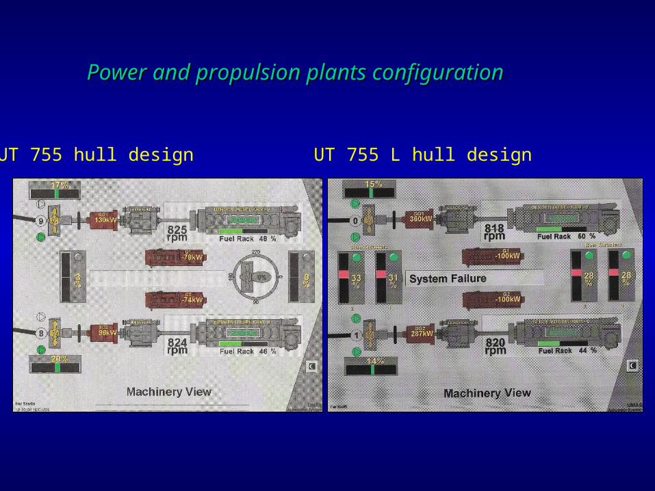
Power and propulsion plants configurationPower and propulsion plants configuration
UT 755 L hull designUT 755 hull design

z(X,t) - complex number plane position for system X is:
where: p(X, t) - number of basic components r(X, t) - number of standby components i - imaginary unit
For a given moment of time t≥0 the total number of components J(X,t) in the system X equals:
where: J(X,0) - size of the system X at t=0 JREST - number of components of the system X that have been failed till the time t.
Redundancy in different DP classesRedundancy in different DP classes

Components redundancy in Components redundancy in power and propulsion plant systemspower and propulsion plant systems
ES1-1 – DP control unitES1-2 – DP supervision stationES1-3 – manual control system ES2-1 – main generator setsES2-2 – main switchboardES2-3 – gensets auxiliary systemsES2-4 – mains switchboard busesES3-1 – ship’s main propulsion unitES3-2 – main propulsion rudderES4-1 – uninterrupted power supplyES4-2 – battery setES4-3 – emergency power plantES5-1 – gyrocompassES5-2 – anemometer

For the subsystem X with a threshold k-out-of-n structure composed of identical components EX the system reliability is:
For the threshold structure k-out-of-n composed of components E1, E2,…En with various reliability characteristics system reliability is:
Reliability calculation based on redundancy modelReliability calculation based on redundancy model

Reliability calculation Reliability calculation for for DPDP thrusters thrusters (for(for exponentional failures distribution and exponentional failures distribution and generic datageneric data))

Final conclusionFinal conclusion
Component redundancy model allows to compare different redundancy classes (DP Classes)
Component redundancy model allows to compare different systems in same redundancy class
Component redundancy model allows to number of transformations and particular measures estimation
There is possibility of application of redundancy model for reliability estimation
Thank you for attentionThank you for attention