Isogeometric nonlinear bending and buckling analysis · PDF fileIsogeometric nonlinear bending...
30
Isogeometric nonlinear bending and buckling analysis of variable-thickness composite plate structures T. Le-Manh a , Q. Huynh-Van b , Thu D. Phan c , Huan D. Phan d , H. Nguyen-Xuan e,* a Faculty of Civil Engineering, HCMC University of Technology (HUTECH), Vietnam b Faculty of Mechanical Engineering, Nguyen Tat Thanh University, Vietnam c Faculty of Mechanical Engineering, Ho Chi Minh City Vocational College, Vietnam d Faculty of Mechanical Engineering, Ho Chi Minh City University of Technology, Vietnam e Duy Tan university, Danang, Vietnam Abstract This paper investigates nonlinear bending and buckling behaviours of composite plates characterized by a thickness variation. Layer interfaces are described as functions of inplane coordinates. Top and bottom surfaces of the plate are sym- metric about the midplane and the plate could be considered as a flat surface in analysis along with thickness parameters which vary over the plate. The variable thickness at a certain position in the midplane is modeled by a set of control points (or thickness-parameters) through NURBS (Non-Uniform Rational B-Spline) ba- sic functions. The knot parameter space which is referred in modelling geometry and approximating displacement variables is employed for approximating thick- ness, simultaneously. The use of quadratic NURBS functions results in C 1 conti- nuity of modeling variable thickness and analyzing solutions. Thin to moderately thick laminates in bound of first-order shear deformation theory (FSDT) are taken into account. Strain-displacement relations in sense of von-Karman theory are employed for large deformation. Riks method is used for geometrically nonlinear analysis. The weak form is approximated numerically by the isogeometric analy- sis (IGA), which has been found to be a robust, stable and realistic numerical tool. Numerical results confirm the reliability and capacity of the propose method. Keywords: Composite plates, Variable thickness, Nonlinear analysis, Isogeometric analysis * Corresponding author. Email: [email protected] Preprint submitted to Elsevier February 21, 2018 arXiv:1604.01367v1 [cs.CE] 3 Apr 2016
Transcript of Isogeometric nonlinear bending and buckling analysis · PDF fileIsogeometric nonlinear bending...

Isogeometric nonlinear bending and buckling analysisof variable-thickness composite plate structures
T. Le-Manha, Q. Huynh-Vanb, Thu D. Phanc, Huan D. Phand, H. Nguyen-Xuane,∗
aFaculty of Civil Engineering, HCMC University of Technology (HUTECH), VietnambFaculty of Mechanical Engineering, Nguyen Tat Thanh University, Vietnam
cFaculty of Mechanical Engineering, Ho Chi Minh City Vocational College, VietnamdFaculty of Mechanical Engineering, Ho Chi Minh City University of Technology, Vietnam
eDuy Tan university, Danang, Vietnam
Abstract
This paper investigates nonlinear bending and buckling behaviours of compositeplates characterized by a thickness variation. Layer interfaces are described asfunctions of inplane coordinates. Top and bottom surfaces of the plate are sym-metric about the midplane and the plate could be considered as a flat surface inanalysis along with thickness parameters which vary over the plate. The variablethickness at a certain position in the midplane is modeled by a set of control points(or thickness-parameters) through NURBS (Non-Uniform Rational B-Spline) ba-sic functions. The knot parameter space which is referred in modelling geometryand approximating displacement variables is employed for approximating thick-ness, simultaneously. The use of quadratic NURBS functions results in C1 conti-nuity of modeling variable thickness and analyzing solutions. Thin to moderatelythick laminates in bound of first-order shear deformation theory (FSDT) are takeninto account. Strain-displacement relations in sense of von-Karman theory areemployed for large deformation. Riks method is used for geometrically nonlinearanalysis. The weak form is approximated numerically by the isogeometric analy-sis (IGA), which has been found to be a robust, stable and realistic numerical tool.Numerical results confirm the reliability and capacity of the propose method.
Keywords: Composite plates, Variable thickness, Nonlinear analysis,Isogeometric analysis
∗Corresponding author. Email: [email protected]
Preprint submitted to Elsevier February 21, 2018
arX
iv:1
604.
0136
7v1
[cs
.CE
] 3
Apr
201
6

1. Introduction
Composite materials are extensively employed in industry varying from largescale structures such as aircraft bodies, ship hulls to specific components of trans-port vehicles. Particularly, variable thickness panels are widely applicable andhence requiring appropriate approaches for analysis and design. A number ofstudies investigated isotropic beams and plates with the thickness change. Ana-lytical analysis of flexural bars of uniform and variable thickness was presented byFertis [1]. Ohga et al. [2] presented the transfer-matrix method for buckling anal-ysis of thin-walled structures with variable thickness cross sections. Timoshenkoand Woinowsky-Krieger [3] gave solutions of circular plates of nonuniform thick-ness in some particular cases. Wu and Liu [4] investigated free vibration analysisof variable thickness circular plates using the generalized differential quadraturerule. Buckling analysis of rectangular plates of linearly tapered thickness wasconsidered by Eisenberger and colleagues [5, 6] using the extended Kantorovichmethod. Theories for analysis of variable thickness composite plates were alsopresented. Ganesan and Liu [7] carried out the nonlinear buckling analysis andthe prediction of the first-ply failure of tapered laminated plates under uniax-ial compression. Besides, a number of works investigated laminated compositeplates with thickness change caused by ply drop [8, 9]. However, most of stud-ies considered the linear change of thickness and there is a lack of approachesfor composite plates with complex nonuniform thickness. Accordingly, in thiswork, a numerical method considering the laminated composite plates of variablethickness is proposed based on isogeometric analysis in which the thickness of theplates is approximated from a set of control thickness parameters using NURBSbasis functions.
The idea of using Non-Uniform Rational B-Spline basis functions in finite el-ement analysis procedure was presented by Hughes et al. [10, 11] in so-called iso-geometric analysis. The method filled the gap between geometric design based onNURBS (see [12]) and structural analysis. The smoothness and high continuity inNURBS-based finite element meshes promise more accurate solutions. Over thelast decade, many efforts have been investigated in developing the method suchas global refinement techniques [10, 13], local refinement techniques [14, 15, 16,17, 18], quadrature rules [19, 20]. Analysis of various plate structures includingvibration, bending, buckling, postbuckling and nonlinear thermomechanical sta-bility based on IGA was widely investigated in [21, 22, 23, 24, 25, 26, 27, 28, 29,30, 31, 32, 33, 34, 35, 36, 37, 38, 39, 40, 41, 42, 43, 44] and so on.
Nonlinear bending and buckling analysis of variable thickness composite plates
2
are conducted in this work. Kinematics is based on first-order shear deforma-tion theory (FSDT) in considering the global behavior of structures. von-Karmanstrain-displacement relations including geometric imperfections which were pre-sented in the works of Le-Manh and Lee [27, 28] in investigating postbuckling oflaminated composited plates are employed. Governing equations are constructedbased on the virtual displacement principle of energy approach. In the isogeomet-ric analysis framework, the 2-dimensional parameter space which is referred inconstructing geometry and finite element model is also the one of thickness ap-proximation. Surfaces of the plate could be arbitrarily defined, in assumption ofbeing symmetric about the midplane, and then the thickness will be interpolatedfrom a set of control thickness parameters using NURBS basis. This providesa flexible solution in modeling smooth nonuniform surfaces while plate theoriesare applicable. C1 continuous requirements in modeling variable thickness andanalyzing solutions are achieved by the use of quadratic NURBS elements. Riksalgorithm is employed for geometrically nonlinear analysis. Numerical problemsconsisting of isotropic and laminated composite plates in various boundary con-ditions are carried out. Variable thickness examples are defined and examined indifferent amplitudes in order to demonstrate the applicability as well as accuracyof the present method.
The article is outlined beginning with a general introduction of isogeomet-ric analysis. A brief of theoretical formulations focusing on the adjustment ofkinematics and the nonuniform thickness treatment is presented in Section 3. Nu-merical examples describing nonlinear bending and buckling behavior of variablethickness composite plates are carried out in next Section. Some concluding re-marks are drawn at last.
2. Isogeometric analysis
A brief recall of NURBS-based geometry and the framework of isogeometricanalysis are presented in this section.
2.1. NURBS basis functionsA knot vector which defines the parameter space is a set of non-decreasing
real numbers,
Ξ = {ξ1, ξ2, ..., ξn+p+1} (1)
3

where ξi is a knot and interval [ξ1, ξn+p+1] is called a patch. A knot vector is openif the first and the last knot have the multiplicity p+ 1, and uniform if the otherknots ξi are in uniform space.
Assuming Ξ is an open uniform knot vector, B-Spline basis functions of orderp ≥ 0 are constructed using the following recursive formula [12],
Ni,0(ξ) =
{1 , if ξi ≤ ξ ≤ ξi+1
0 , otherwise(2a)
Ni,p(ξ) =ξ − ξiξi+p − ξi
Ni,p−1(ξ) +ξi+p+1 − ξξi+p+1 − ξi+1
Ni+1,p−1(ξ) (2b)
B-Spline basis function has important properties such as,
• Non-negative: Ni,p(ξ) ≥ 0,∀ξ,
• Ni,p(ξ) is locally supported in the interval [ξi, ξi+p+1],
• Constitute a partition of unity:∑n
i=1Ni,p(ξ) = 1,∀ξ.
Considering a 2-dimensional parameter space, the basis functions are derived as,
Rpqij (ξ, η) = Ni,p (ξ)Mj,q (η) (3)
where i = 1, 2, ..., n and j = 1, 2, ...,m. Ni,p (ξ) and Mj,q (η) are the basis oforder p and q in Ξ = {ξ1, ξ2, ..., ξn+p+1} and H = {η1, η2, ..., ηm+q+1} directions,respectively.
B-Spline surface is a tensor product of a control net of n×m control points{Bij} ∈ Rd and 2-dimensional B-Spline basis functions,
S (ξ, η) =n∑i=1
m∑j=1
Rpqij (ξ, η)Bij (x, y, z) (4)
4
B-Spline surface is C∞ continuous inside a knot span [ξi, ξi+1] and Cp−1
continuous at a single knot ξi. NURBS surface is obtained by projecting anonrational B-Spline surface Sw (ξ, η) from a homogeneous coordinate in Rd+1
space onto physical Rd space, which has a final form similar to Eq. (4) with therational NURBS basis defined by
Rpqij (ξ, η) =
Ni,p (ξ)Mj,q (η)wijn∑i=1
m∑j=1
Ni,p (ξ)Mj,q (η)wij
(5)
where wij ≥ 0 is the weight of control point Bwij = (wijxij, wijyij, wijzij, wij)
T
in homogeneous space.
2.2. Isogeometric analysis modelIsogeometric analysis proposed by Hughes et al. [10] employs NURBS ba-
sis for geometrical modelling and finite element approximations, simultaneously.More accurate solutions compared with standard finite element analysis of com-posite structures are usually obtained due to the higher-order continuity in theNURBS meshes, while using less total degrees-of-freedom (DOFs). In the anal-ysis domain, dependent displacement variables and other geometric informationcould be approximated by the following formula,
s =nC∑c=1
Rcsc (6)
where nC is the number of control points, sc are control parameters (i.e.displacements of control points, initial deviation of control points or controlthickness parameters, etc) and Rc are 2-dimensional NURBS basis functions.
In finite element subdomain, Eq. (6) could be written as,
se =nCe∑c=1
Recsec (7)
where nCe is the number of control points per element, sec are control parametersof corresponding element and Re
c are NURBS basis functions evaluated withrespect to parameter coordinates which define the element in physical space.
5

3. Theoretical formulation
In this work, first-order shear deformation is employed to consider thin andmoderately thick composite plates. The kinematics of FSDT theory including ge-ometric imperfections is carried out and constitutive relations of composite platesof variable thickness are presented in the isogeometric analysis framework.
3.1. KinematicsAssume that midplane is the origin of material coordinate system of a perfectly
flat plate. The displacement field in FSDT is defined as follows [45, 46],
ux(x, y, z) = u(x, y) + zφx(x, y) (8a)uy(x, y, z) = v(x, y) + zφy(x, y) (8b)uz(x, y, z) = w(x, y) (8c)
where (ux, uy, uz) and (u, v, w) are the displacements of a point in body anddisplacements of a point on midplane along (x, y, z) directions, respectively. φxand φy are the rotations of transverse normal of the mid-plane about the y and xaxes, respectively.
When the initial configuration of the plate contains geometric imperfections, i.e.initial deviations along out-of-plane direction from being perfectly flat, this smalldeflection can be described as a function of inplane coordinates,
uz(x, y, z) = w(x, y) (9)
In a recent work, Le-Manh and Lee [27] applied geometric mode shapeimperfection in investigating postbuckling behavior of rectangular compositeplates. The effect of imperfection magnitude was taken into account. Thedeformed geometry of imperfect plate in FSDT could be depicted in Fig. 1. Thetotal deflection is the summation of w(x, y) and w(x, y). Nonlinearstrains-displacement relations in sense of von-Karman theory includingimperfections can be arranged into the inplane strains, curvatures and shearstrains as follows,
6

ε =
∂u∂x
+ 12
(∂w∂x
)2+ ∂w
∂x∂w∂x
∂v∂y
+ 12
(∂w∂y
)2
+ ∂w∂y
∂w∂y
∂u∂y
+ ∂v∂x
+ ∂w∂x
∂w∂y
+ ∂w∂x
∂w∂y
+ ∂w∂x
∂w∂y
(10a)
κ =
∂φx∂x∂φy∂y∂φx∂y
+ ∂φy∂x
(10b)
γ =
{φy + ∂w
∂y+ ∂w
∂y
φx + ∂w∂x
+ ∂w∂x
}(10c)
3.2. Constitutive relations for composite plates of variable thicknessHere, composite plates whose geometry is symmetric about the midplane are
taken into account, and hence their initial configuration still can be modeled as aflat surface. The thickness of the layer k at a certain position on the midplane isa function of inplane coordinates h(k)(x, y) which could be approximated from aset of control thickness parameters h(k)
c using 2-dimensional NURBS basis:
h(k) =
nCh∑c=1
Rch(k)c (11)
Basically, the number of control points nC and the number of control thicknessparameters nCh could be different, and the parameter spaces for each of themcould be also separated. However, it is more convenient to use a uniqueparameter space in the analysis framework. Accordingly, one control thicknessparameter will be assigned at each control point to define a lamina thickness. Fora composite laminate made of n laminae, there will be n× nC control thicknessparameters in total. The thickness of the laminate is derived as follows
h =n∑k=1
h(k) =n∑k=1
nC∑c=1
Rch(k)c =
nC∑c=1
Rc
(n∑k=1
h(k)c
)(12)
Due to the change of thickness, the extensional stiffness matrix A, theextensional-bending coupling matrix B, bending matrix D and transverse shearstiffness matrix As vary over the plate and can be computed by
7

A =n∑k=1
Q(k)(_zk+1 −
_zk)
(13)
B =1
2
n∑k=1
Q(k)(
_z
2
k+1 −_z
2
k
)(14)
D =1
3
n∑k=1
Q(k)(
_z
3
k+1 −_z
3
k
)(15)
As = Ks
n∑k=1
Q(k)s
(_zk+1 −
_zk)
(16)
where Q(k) and Qs are the global plane-stress stiffness and shear stiffness oflamina (k), _
zk (k = 1, 2, ..., n+ 1) are the coordinates of interfaces along normaldirection determined at a specific position on midplane via Gauss quadraturepoints in the integral loop and Ks is shear correction factor.
The constitutive relations are then derived as follows,
NMQ
=
A B 0B D 00 0 As
εκγ
(17)
where N, M, Q is the vectors of inplane force resultants, moment resultants andtransverse shear force resultants, respectively.
8
4. Numerical examples
In this section, numerical problems including bending and buckling analy-sis of isotropic and composite plates of variable thickness are investigated to il-lustrate the application of the proposed approach. These plates vary from thinto moderately thick in bound of FSDT. The finite element meshes of full platesare constructed using quadratic NURBS elements in nonlinear parameterizationswhich lead to regular meshes in physical space. Reduced integration techniqueis employed to evaluate the transverse shear terms in Gauss quadrature. Conver-gence tests are not shown in details for the sake of brevity. For illustration, 6×6quadratic NURBS elements are employed for analysis. Mesh refinement will bestated as necessary. Riks method is used for nonlinear analysis with the toleranceof displacement convergence δ = 10−3. In buckling analysis, geometric imperfec-tion is applied on the plates in primary mode shape with the normalized amplitude∆ = wc/a = 10−5, (see Ref. [27]).
The arc length methods for nonlinear analysis have been well known for thecapacity of tracking equilibrium paths through limit point at which the tangentstiffness matrix KT becomes singular. Among the methods, Riks algorithm iswidely used. Reddy [47] gave an explanation of the scheme and provided a detailof computational algorithm. The residual vector is a function of bothdisplacement u and load parameter λ: R (u + w, λ) = K (u + w)− λF; wherew is the imperfection vector, K is the direct stiffness matrix and F is thepreference load vector. In this study, the tolerance of displacement convergenceis δ = 10−3.
The non-dimensional material properties are defined as: For isotropic plates: E =3×10⁶ and ν = 0.25, and for composite plate: E1/E2 = 25, G12/E2 = 0.5, G23/E2
= 0.2, G13 = G12 and ν = 0.25.
4.1. Isotropic square plates of linearly tapered thickness along x directionThe model of a square plate with the thickness h linearly decreasing along x
direction is depicted in Fig. 2. Inplane dimension of the plate is a×a. The taperedratio α, i.e. the slope of the tapered surface, is defined by
α =hmax − h
a=h− hmin
a(18)
9

where h is the uniform thickness, α = 0, of the plate which has the same volumewith those of tapered thickness. The top surface of the plate could be describedas the following function
z(x) =h
2− αx (19)
Moreover, the bottom surface is geometrically symmetric with the top surfaceabout the midplane. In this example, isotropic square plates are investigated. Thenon-dimensional geometry and uniform thickness are assumed as a=10 andh=0.2 (a/h = 50). In bending test, the plate is clamped at AD and subjected toincreasing uniform transverse load, deflection of point M is measured. Inbuckling test, all 4 edges of the plate is simply-supported (SS1), uniaxialcompression load is applied in x direction and central transverse displacement atorigin O is measured:
Clamped at AD : u = v = w = φx = φy = 0 (20)
SS1 at AD and BC : w = φy = 0 (21a)SS1 at AB and CD : w = φx = 0 (21b)
The transverse displacement w, uniform transverse load q and compression loadN are normalized as
w =w
h(22)
q =qa4
Eh4(23)
λ =Na2
π2D(24)
where D is the flexural rigidity of the plate of uniform thickness , i.e. taperedratio α = 0.
10

The solutions are given in Fig. 3 and Fig. 4. In bending test, linear responses ofthe cantilever plates under uniform transverse load are obtained. It is alsoreasonable that the larger tapered thickness ratio α results in smaller deflection.Fig. 4 presents buckling and postbuckling path of imperfect isotropic squareplates under uniaxial compression load in x direction. The results are in goodagreement with ones of uniform thickness α = 0 given by Sundaresan et al. [48]and Le-Manh and Lee [27]. It can be seen that when increasing the slope oftapered surfaces, the critical load of the plate significantly decreases. Thisindicates that stability analysis should be taken into account in designing taperedstructures.
4.2. Isotropic square plates of linearly tapered thickness along the diagonal di-rection
In this problem, isotropic square plates of tapered thickness in two dimensionsare investigated. The thickness h is gradually changes along the diagonal DB ofthe plate, Fig. 5. In this case, the tapered ratio α and the top surface of the platecould be derived as follows
α =hmax − ha√
2=h− hmin
a√
2(25)
z(x, y) =h
2− α√
2x+
α√2y (26)
It should be noted the plates with different tapered ratios have the same volume.Non-dimensional geometry and normalized parameters are similar to theprevious example. In bending test, edge AD and CD are under simply-supported(SS2) in Eq. (27). The plate is subjected to increasing uniform transverse loadand corresponding transverse displacement is computed at the corner point B. Inbuckling test, boundary conditions SS1 in Eq. (21) are applied and the plate isunder biaxial compression loads in x and y directions:
SS2 at AD and DC : u = v = w = 0 (27)
The results of bending test are shown in Fig. 6. It is interesting to observe thedifferent behavior in linear and nonlinear analysis. When increasing the taperedratio α the linear bending deflection decreases, however, when the transversedisplacement is considerably large, higher tapered ratio results in larger nonlinearbending deflection. Buckling and postbuckling path of the isotropic square platesunder biaxial compression loads are plotted in Fig. 7. The critical buckling loadnotably decreases when the slope of tapered surfaces increases.
11

4.3. Symmetric cross-ply (0/90)s laminated composite square plate of linearly ta-pered thickness along x direction
Considering a cantilever symmetric cross-ply (0/90)s square laminated com-posite plate of tapered thickness along x direction. The non-dimensional inplanedimension and uniform thickness of the plate are a=10 and h=0.2 (a/h = 50).Cross section of the laminate in x − z plane is depicted in Fig. 8. The thicknessof each ply is equal together at any position over the plate. Boundary and loadconditions for bending and buckling analysis are similar to example 4.1. Uniformtransverse load q and compression load N are normalized as follows,
q =qa4
E2h4(28)
λ =Na2
E2h3(29)
The obtained transverse displacement versus loading curves are shown in Fig. 9for bending analysis and Fig. 10 for buckling analysis. Behavior of the cantileversymmetric cross-ply laminate has the similar pattern with the clamped isotropicplate. The deflection of the cantilever composite plate decreases when thetapered ratio α increases, and the buckling load also drops considerably.
4.4. Symmetric angle-ply (45/-45)s laminated composite square plate of linearlytapered thickness along the diagonal direction
A symmetric angle-ply (45/-45)s square plate of linearly tapered thicknessalong diagonal direction (see Fig. 5) is taken in account here. Boundary and loadconditions are applied same in example 4.2. The thickness of each ply is equaltogether at any position over the plate. The inplane dimensions, uniform thicknessand normalized parameters are similar to example 4.3.
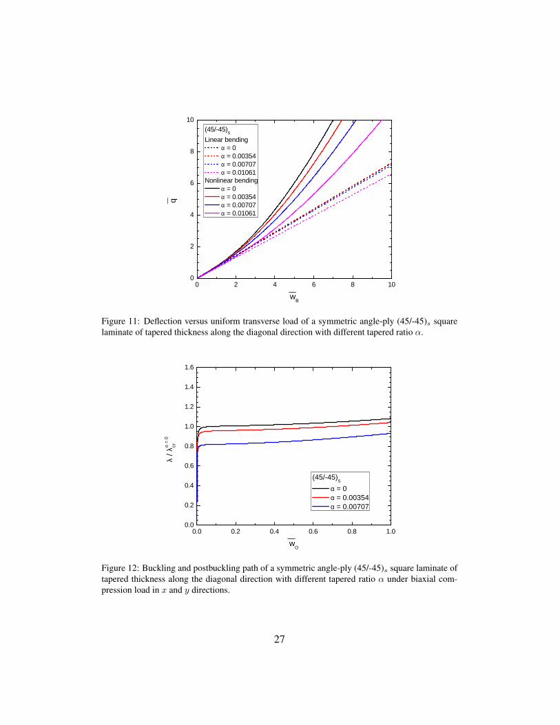
The results of bending test are given in Fig. 11. It can be seen that in linearbending analysis there is an unpredictable development of the deflection withrespect to the increase of tapered ratio α. Therefore, nonlinear analysis should beconsidered in designing plates of tapered thickness, especially in cases ofcomplex boundary conditions. Besides, critical load of the symmetric angle-ply(45/-45)s laminate under biaxial compression loads notably drops whenincreasing the slope of the tapered surface, see Fig. 12.
12

4.5. Composite square plates of thickness as a sine waveIn this example, nonlinear buckling of composite plates including isotropic
square plate and symmetric cross-ply (0/90)s laminated composite square plates ofvariable thickness is examined. The top surface of the plates is described as a sinewave function, Eq. (30), and the bottom surface is geometrically symmetric withthe top surface about the midplane. The cross section of the plates are illustratedin Fig. 13. Non-dimensional inplane dimension and the uniform thickness area=10 and h=0.5 (a/h=20).
z(x) = αh sin (2πnx
a+π
2)+h
2(30)
where α is the parameter that controls the amplitude of the sine wave and n is tochange the number of wavelength. The plates are subjected to uniaxialcompression load in y direction. When increasing the number of wavelength, theplate surfaces are more complex and it is required mesh refinement to obtainconvergence solution. In this works, the mesh of 6×6 quadratic NURBSelements is used for α = 0, 12×12 quadratic NURBS elements for α 6= 0 andn=1,2 and 3.
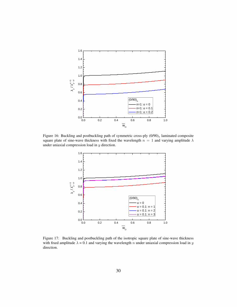
The effects of the amplitude parameter α and the number of wavelength n to thecritical load of the plates will be investigated. The obtained bifurcation behaviorin nonlinear buckling analysis is given in Fig. 14 and Fig. 15 for the isotropicplate, and Fig. 16 and Fig. 17 for the cross-ply laminate. It can be remarked thatα and n slightly affect the buckling and postbuckling path of the isotropic plateswhile the buckling load of the cross-ply laminate significantly fluctuatesdepended on these parameters. In details, when the wavelength is fixed at n = 1and increasing the amplitude of sine wave, Fig. 16, the critical load of thecross-ply laminate dramatically drops in comparison with the laminate ofuniform thickness. On the other hand, when the amplitude of sine wave is fixedat α = 0.1 and changing the shape the plates by increasing the number ofwavelength, buckling load of the cross-ply laminate decreases considerably(n=1), but it rises again and approaches a certain value close to the critical loadin case of uniform thickness (n=2,3), see Fig. 17.
5. Conclusions
Nonlinear bending and buckling analysis of symmetric composite plates ofvariable thickness based on the framework of isogeometric analysis were pre-
13

sented in this work. Control thickness parameters were introduced to approxi-mate the thickness which varies over the plates. This allows us model smoothnon-uniform surfaces while using plate theories for analysis. Numerical exampleswere provided to illustrate the accuracy and applicability of the method as wellas present some interesting features in nonlinear analysis of isotropic and lami-nated composite plates of variable thickness. According to the present methodand obtained numerical solutions, some conclusions could be drawn:
(i) The approach successfully obtains nonlinear bending and buckling behaviorof variable thickness composite plates. Numerical problems of isotropic andlaminated composite plates with different kinds of thickness changes weredefined, giving reliable solutions in comparison with other reference methods.
(ii) Nonlinear analysis should be carried out in designing plates of variablethickness, especially composite laminates whose critical load could considerablydecrease in comparison with ones of uniform thickness having the same volume.
14

References
References
[1] Fertis DG. Nonlinear Mechanics. CRC Press; 1993.
[2] Ohga M, Shigematsu T, Kawaguchi K. Buckling analysis of thin-walledmembers with variable thickness. J Struct Eng 1995;121(6):919–24.
[3] Timoshenko S, Woinowsky-Krieger S. Theory of plates and shells. McGraw-hill; 1959.
[4] Wu TY, Liu GR. Free vibration analysis of circular plates with variablethickness by the generalized differential quadrature rule. Thin-Walled Struc-tures 2001;38:7967–80.
[5] Eisenberger M, Alexandrov A. Buckling loads of variable thickness thinisotropic plates. Thin-Walled Structures 2003;41(9):871–89.
[6] Shufrin I, Eisenberger M. Stability of variable thickness shear de-formable platesfirst order and high order analyses. Thin-Walled Structures2005;43(2):189–207.
[7] Ganesan R, Liu DY. Progressive failure and post-buckling response oftapered composite plates under uni-axial compression. Compos Struct2008;82(2):159–76.
[8] Dinardo MT, Lagace PA. Buckling and postbuckling of laminated compositeplates with ply dropoffs. AIAA Journal 1989;27:1392–8.
[9] Varughese B, Mukherjee A. A ply drop-off element for analysis of taperedlaminated composites. Compos Struct 1997;39:123–44.
[10] Hughes TJR, Cottrell JA, Bazilevs Y. Isogeometric analysis: Cad, finiteelements, nurbs, exact geometry and mesh refinement. Comput MethodsAppl Mech Eng 2005;194:4135–95.
[11] Cottrell JA, Hughes TJR, Bazilevs Y. Isogeometric analysis: toward inte-gration of CAD and FEA. John Wiley and Sons; 2009.
[12] Piegl L, Tiller W. The NURBS book (Monographys in Visual Communica-tion), 2nd edition. Springer-Verlag; 1997.
15

[13] Cottrell JA, Hughes TJR, Reali A. Studies of refinement and continu-ity in isogeometric structural analysis. Comput Methods Appl Mech Eng2007;196:4160–83.
[14] Bazilevs Y, Calo VM, Cottrel JA, Evans JA, Hughes TJR, Lipson S, et al.Isogeometric analysis using t-splines. Comput Methods Appl Mech Eng2010;199:229–63.
[15] Nguyen-Thanh N, Nguyen-Xuan H, Bordas S, Rabczuk T. Isoge-ometric analysis using polynomial splines over hierarchical t-meshesfor two-dimensional elastic solids. Comput Methods Appl Mech Eng2011;200:1892–908.
[16] Nguyen-Thanh N, Kiendl J, Nguyen-Xuan H, Wucher R, Bletzinger KU,Bazilevs Y, et al. Rotation free isogeometric thin shell analysis using pht-splines. Comput Methods Appl Mech Eng 2011;200:3410–24.
[17] Kleiss SK, Juttler B, Zulehner W. Enhancing isogeometric analysis by afinite element-based local refinement strategy. Comput Methods Appl MechEng 2012;213-216:168–82.
[18] Schillinger D, Dede L, Scott MA, Evans JA, Borden MJ, Rank E, et al. Anisogeometric design-through-analysis methodology based on adaptive hier-archical refinement of nurbs, immersed boundary methods, and t-spline cadsurfaces. Comput Methods Appl Mech Eng 2012;249-252:116–50.
[19] Hughes TJR, Reali A, Sangalli G. Efficient quadrature for nurbs-based iso-geometric analysis. Comput Methods Appl Mech Eng 2010;199:301–13.
[20] Auricchio F, Calabro F, Hughes TJR, Reali A, Sangalli G. A simple algo-rithm for obtaining nearly optimal quadrature rules for nurbs-based isogeo-metric analysis. Comput Methods Appl Mech Eng 2012;249-252:15–27.
[21] Luu AT, N. I. Kim NI, Lee J. Nurbs-based isogeometric vibration analysisof generally laminated deep curved beams with variable curvature. ComposStruct 2015;119:150–65.
[22] Kapoor H, Kapania RK. Geometrically nonlinear nurbs isogeometricfinite element analysis of laminated composite plates. Compos Struct2012;94:3434–47.
16

[23] Thai CH, Nguyen-Xuan H, Nguyen-Thanh N, Le TH, Nguyen-Thoi T,Rabczuk T. Static, free vibration, and buckling analysis of laminated com-posite reissnermindlin plates using nurbs-based isogeometric approach. IntJ Numer Methods Eng 2012;91:571–603.
[24] Thai CH, Ferreira AJM, Carrera E, Nguyen-Xuan H. Isogeometric analysisof laminated composite and sandwich plates using a layerwise deformationtheory. Compos Struct 2013;104:196–214.
[25] Nguyen-Xuan H, Thai CH, Nguyen-Thoi T. Isogeometric finite elementanalysis of composite sandwich plates using a higher order shear deforma-tion theory. Compos Part B 2013;55:558–74.
[26] Nguyen VP, Nguyen-Xuan H. High-order b-splines based finite ele-ments for delamination analysis of laminated composites. Compos Struct2013;102:261–75.
[27] Le-Manh T, Lee JH. Postbuckling of laminated composite plates usingnurbs-based isogeometric analysis. Compos Struct 2014;109:286–93.
[28] Le-Manh T, Lee JH. Stacking sequence optimization for maximum strengthsof laminated composite plates using genetic algorithm and isogeometricanalysis. Compos Struct 2014;116:357–63.
[29] Guo Y, Nagy AP, Grdal Z. A layerwise theory for laminated composites inthe framework of isogeometric analysis. Compos Struct 2014;107:447–57.
[30] Guo Y, Ruess M, Grdal Z. A contact extended isogeometric layerwise ap-proach for the buckling analysis of delaminated composites. Compos Struct2014;116:55–66.
[31] Tran LV, Ferreira AJM, Nguyen-Xuan H. Isogeometric analysis of function-ally graded plates using higher-order shear deformation theory. CompositesPart B: Engineering 2013;51:368–83.
[32] Tran LV, Thai CH, Nguyen-Xuan H. An isogeometric finite element for-mulation for thermal buckling analysis of functionally graded plates. FiniteElements in Analysis and Design 2013;73:65–76.
[33] Nguyen-Xuan H, Tran LV, Thai CH, Kulasegaram S, Bordas SPA. Isoge-ometric analysis of functionally graded plates using a refined plate theory.Composites Part B: Engineering 2014;64:222–34.
17

[34] Hosseini S, Remmers JJ, Verhoosel CV, Borst RD. An isogeometric con-tinuum shell element for non-linear analysis. Comput Methods Appl MechEng 2014;271:1–22.
[35] Kapoor H, Kapania RK, Soni SR. Interlaminar stress calculation in com-posite and sandwich plates in nurbs isogeometric finite element analysis.Compos Struct 2013;106:537–48.
[36] Nguyen-Thanh N, Valizadeh N, Nguyen MN, Nguyen-Xuan H, Zhuang X,Areias P, et al. An extended isogeometric thin shell analysis based on kirch-hofflove theory. Comput Methods Appl Mech Eng 2015;284:265–91.
[37] Kiendl J, Bletzinger KU, Linhard J, Wuchner R. Isogeometric shell anal-ysis with kirchhoff-love elements. Comput Methods Appl Mech Eng2009;198:3902–14.
[38] Benson DJ, Bazilevs Y, Hsu MC, Hughes TJR. Isogeometric shell anal-ysis: The reissner-mindlin shell. Comput Methods Appl Mech Eng2010;199:276–89.
[39] Benson DJ, Bazilevs Y, Hsu MC, Hughes TJR. A large deforma-tion, rotation-free, isogeometric shell. Comput Methods Appl Mech Eng2011;200:1367–13789.
[40] Echter R, Oesterle B, Bischoff M. A hierarchic family of isogeometric shellfinite elements. Comput Methods Appl Mech Eng 2013;254:170–80.
[41] Kiendl J, F. Auricchio L. Beirao da Veiga CL, Reali. A. Isogeometric col-location methods for the reissnermindlin plate problem. Comput MethodsAppl Mech Eng 2015;284:489–507.
[42] Deng X, Korobenko A, Yan J, Bazilevs Y. Isogeometric analysis of contin-uum damage in rotation-free composite shells. Comput Methods Appl MechEng 2015;284:349–72.
[43] Nguyen LB, Thai CH, Nguyen-Xuan H. A generalized unconstrained the-ory and isogeometric finite element analysis based on bezier extraction forlaminated composite plates. Eng Comput 2016;32:1–19.
[44] Tran LV, Phung-Van P, Lee J, Wahab M, Nguyen-Xuan H. Isogeomet-ric analysis for nonlinear thermomechanical stability of functionally gradedplates. Compos Struct 2016;140:655–67.
18

[45] Reddy JN. Mechanics of laminated composite plates and shells, 2nd edition.CRC Press; 2004.
[46] Huu-Tai T, Choi D. A simple first-order shear deformation theory for lami-nated composite plates. Compos Struct 2013;106:754–63.
[47] Reddy JN. An introduction to nonlinear finite element analysis. OxfordUniversity Press, New York; 2004.
[48] Sundaresan P, Singh G, Rao GV. Buckling and postbuckling analysis ofmoderately thick laminated rectangular plates. Comput Struct 1996;61:79–86.
19

List of figures
Figure 1: Deformed geometry of imperfect plate in FSDT.
20

Figure 2: Model of a square plate of linearly tapered thickness along x direction.
21

0 2 4 6 8 1 00
4
8
1 2
1 6
2 0
q
w M
α = 0 α = 0 . 0 0 5 α = 0 . 0 1 0 α = 0 . 0 1 5
Figure 3: Deflection versus uniform transverse load of a cantilever isotropic square plate of taperedthickness along x direction with different tapered ratio α.
0 . 0 0 . 2 0 . 4 0 . 6 0 . 8 1 . 00 . 0
0 . 2
0 . 4
0 . 6
0 . 8
1 . 0
1 . 2
1 . 4
1 . 6
λ x / λα
= 0 x - cr
w O
α = 0 , Q 8 F E ( S u n d a r e s a n e t . a l [ 5 4 ] ) α = 0 , q u a d r a t i c N U R B S ( L e & L e e [ 2 8 ] ) α = 0 , q u a d r a t i c N U R B S ( p r e s e n t ) α = 0 . 0 0 5 α = 0 . 0 1 0
Figure 4: Buckling and postbuckling path of a simply-supported isotropic square plate of taperedthickness along x direction with different tapered ratio α under uniaxial compression load in xdirection.
22
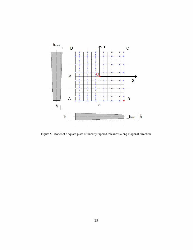
Figure 5: Model of a square plate of linearly tapered thickness along diagonal direction.
23

0 2 4 6 8 1 00
4
8
1 2
1 6
2 0
q
w B
L i n e a r b e n d i n g α = 0 α = 0 . 0 0 3 5 4 α = 0 . 0 0 7 0 7 α = 0 . 0 1 0 6 1
N o n l i n e a r b e n d i n g α = 0 α = 0 . 0 0 3 5 4 α = 0 . 0 0 7 0 7 α = 0 . 0 1 0 6 1
Figure 6: Deflection versus uniform transverse load of an isotropic square plate of tapered thick-ness along diagonal direction with different tapered ratio α.
0 . 0 0 . 2 0 . 4 0 . 6 0 . 8 1 . 00 . 0
0 . 2
0 . 4
0 . 6
0 . 8
1 . 0
1 . 2
1 . 4
1 . 6
λ / λα =
0cr
w O
α = 0 α = 0 . 0 0 3 5 4 α = 0 . 0 0 7 0 7
Figure 7: Buckling and postbuckling path of an isotropic square plate of tapered thickness alongdiagonal direction with different tapered ratio α under biaxial compression loads in x and y direc-tion.
24

Figure 8: Cross section of a symmetric cross-ply (0/90)s laminated composite plate of linearlytapered thickness along x direction in x− z plane.
25

0 2 4 6 8 1 00
4
8
1 2
1 6
2 0
q
w M
( 0 / 9 0 ) S α = 0 α = 0 . 0 0 5 α = 0 . 0 1 0 α = 0 . 0 1 5
Figure 9: Deflection versus uniform transverse load of a symmetric cross-ply (0/90)s square lam-inate of tapered thickness along x direction with different tapered ratio α.
0 . 0 0 . 2 0 . 4 0 . 6 0 . 8 1 . 00 . 0
0 . 2
0 . 4
0 . 6
0 . 8
1 . 0
1 . 2
1 . 4
1 . 6
λ x / λα
= 0
x - cr
w O
( 0 / 9 0 ) S α = 0 α = 0 . 0 0 5 α = 0 . 0 1 0
Figure 10: Buckling and postbuckling path of symmetric cross-ply (0/90)s square laminate oftapered thickness along x direction with different tapered ratio α under uniaxial compression loadin x direction.
26
0 2 4 6 8 1 00
2
4
6
8
1 0
q
w B
( 4 5 / - 4 5 ) SL i n e a r b e n d i n g
α = 0 α = 0 . 0 0 3 5 4 α = 0 . 0 0 7 0 7 α = 0 . 0 1 0 6 1
N o n l i n e a r b e n d i n g α = 0 α = 0 . 0 0 3 5 4 α = 0 . 0 0 7 0 7 α = 0 . 0 1 0 6 1
Figure 11: Deflection versus uniform transverse load of a symmetric angle-ply (45/-45)s squarelaminate of tapered thickness along the diagonal direction with different tapered ratio α.
0 . 0 0 . 2 0 . 4 0 . 6 0 . 8 1 . 00 . 0
0 . 2
0 . 4
0 . 6
0 . 8
1 . 0
1 . 2
1 . 4
1 . 6
λ / λα =
0cr
w O
( 4 5 / - 4 5 ) S α = 0 α = 0 . 0 0 3 5 4 α = 0 . 0 0 7 0 7
Figure 12: Buckling and postbuckling path of a symmetric angle-ply (45/-45)s square laminate oftapered thickness along the diagonal direction with different tapered ratio α under biaxial com-pression load in x and y directions.
27
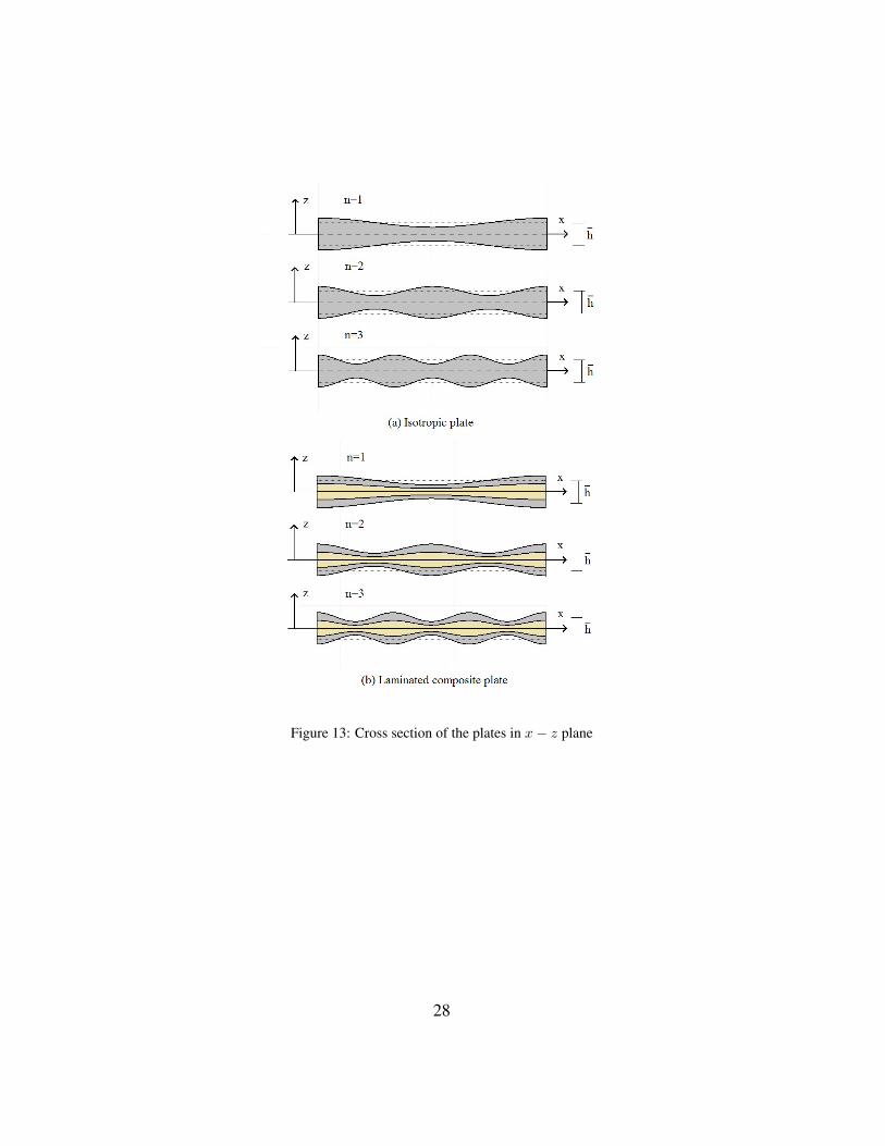
Figure 13: Cross section of the plates in x− z plane
28

0 . 0 0 . 2 0 . 4 0 . 6 0 . 8 1 . 00 . 0
0 . 2
0 . 4
0 . 6
0 . 8
1 . 0
1 . 2
1 . 4
1 . 6
λ y / λα
= 0
y - cr
w O
n = 1 : α = 0 n = 1 : α = 0 . 1 n = 1 : α = 0 . 2
Figure 14: Buckling and postbuckling path of the isotropic square plate of sine-wave thicknesswith fixed the wavelength n = 1 and varying amplitude λ under uniaxial compression load in ydirection.
0 . 0 0 . 2 0 . 4 0 . 6 0 . 8 1 . 00 . 0
0 . 2
0 . 4
0 . 6
0 . 8
1 . 0
1 . 2
1 . 4
1 . 6
λ y / λα
= 0
y - cr
w O
α = 0 α = 0 . 1 : n = 1 α = 0 . 1 : n = 2 α = 0 . 1 : n = 3
Figure 15: Buckling and postbuckling path of the isotropic square plate of sine-wave thicknesswith fixed amplitude λ=0.1 and varying the wavelength n under uniaxial compression load in ydirection.
29
0 . 0 0 . 2 0 . 4 0 . 6 0 . 8 1 . 00 . 0
0 . 2
0 . 4
0 . 6
0 . 8
1 . 0
1 . 2
1 . 4
1 . 6
λ y / λα
= 0
y - cr
w O
( 0 / 9 0 ) S n = 1 : α = 0 n = 1 : α = 0 . 1 n = 1 : α = 0 . 2
Figure 16: Buckling and postbuckling path of symmetric cross-ply (0/90)s laminated compositesquare plate of sine-wave thickness with fixed the wavelength n = 1 and varying amplitude λunder uniaxial compression load in y direction.
0 . 0 0 . 2 0 . 4 0 . 6 0 . 8 1 . 00 . 0
0 . 2
0 . 4
0 . 6
0 . 8
1 . 0
1 . 2
1 . 4
1 . 6
λ y / λα
= 0
y - cr
w O
( 0 / 9 0 ) S α = 0 α = 0 . 1 : n = 1 α = 0 . 1 : n = 2 α = 0 . 1 : n = 3
Figure 17: Buckling and postbuckling path of the isotropic square plate of sine-wave thicknesswith fixed amplitude λ = 0.1 and varying the wavelength n under uniaxial compression load in ydirection.
30