Effect of bending buckling of carbon nanotubes on … of bending buckling of carbon nanotubes on...
12
Effect of bending buckling of carbon nanotubes on thermal conductivity of carbon nanotube materials Alexey N. Volkov, Takuma Shiga, David Nicholson, Junichiro Shiomi, and Leonid V. Zhigilei Citation: J. Appl. Phys. 111, 053501 (2012); doi: 10.1063/1.3687943 View online: http://dx.doi.org/10.1063/1.3687943 View Table of Contents: http://jap.aip.org/resource/1/JAPIAU/v111/i5 Published by the American Institute of Physics. Related Articles Thermoplastic deformation of silicon surfaces induced by ultrashort pulsed lasers in submelting conditions J. Appl. Phys. 111, 053502 (2012) Measurement of the two-dimensional magnetostriction and the vector magnetic property for a non-oriented electrical steel sheet under stress J. Appl. Phys. 111, 07E320 (2012) Deposition of epitaxial BiFeO3/CoFe2O4 nanocomposites on (001) SrTiO3 by combinatorial pulsed laser deposition Appl. Phys. Lett. 100, 092901 (2012) Atomic simulations of effect of grain size on deformation behavior of nano-polycrystal magnesium J. Appl. Phys. 111, 044322 (2012) Axial and lateral lattice strain states under a tensile load in as-reacted and prebent CuNb/Nb3Sn wires using neutron diffraction J. Appl. Phys. 111, 043908 (2012) Additional information on J. Appl. Phys. Journal Homepage: http://jap.aip.org/ Journal Information: http://jap.aip.org/about/about_the_journal Top downloads: http://jap.aip.org/features/most_downloaded Information for Authors: http://jap.aip.org/authors
Transcript of Effect of bending buckling of carbon nanotubes on … of bending buckling of carbon nanotubes on...

Effect of bending buckling of carbon nanotubes on thermal conductivity ofcarbon nanotube materialsAlexey N. Volkov, Takuma Shiga, David Nicholson, Junichiro Shiomi, and Leonid V. Zhigilei Citation: J. Appl. Phys. 111, 053501 (2012); doi: 10.1063/1.3687943 View online: http://dx.doi.org/10.1063/1.3687943 View Table of Contents: http://jap.aip.org/resource/1/JAPIAU/v111/i5 Published by the American Institute of Physics. Related ArticlesThermoplastic deformation of silicon surfaces induced by ultrashort pulsed lasers in submelting conditions J. Appl. Phys. 111, 053502 (2012) Measurement of the two-dimensional magnetostriction and the vector magnetic property for a non-orientedelectrical steel sheet under stress J. Appl. Phys. 111, 07E320 (2012) Deposition of epitaxial BiFeO3/CoFe2O4 nanocomposites on (001) SrTiO3 by combinatorial pulsed laserdeposition Appl. Phys. Lett. 100, 092901 (2012) Atomic simulations of effect of grain size on deformation behavior of nano-polycrystal magnesium J. Appl. Phys. 111, 044322 (2012) Axial and lateral lattice strain states under a tensile load in as-reacted and prebent CuNb/Nb3Sn wires usingneutron diffraction J. Appl. Phys. 111, 043908 (2012) Additional information on J. Appl. Phys.Journal Homepage: http://jap.aip.org/ Journal Information: http://jap.aip.org/about/about_the_journal Top downloads: http://jap.aip.org/features/most_downloaded Information for Authors: http://jap.aip.org/authors

Effect of bending buckling of carbon nanotubes on thermalconductivity of carbon nanotube materials
Alexey N. Volkov,1 Takuma Shiga,2 David Nicholson,1 Junichiro Shiomi,2,a)
and Leonid V. Zhigilei1,a)
1University of Virginia, Department of Materials Science and Engineering, 395 McCormick Road,Charlottesville, Virginia 22904-4745, USA2The University of Tokyo, Department of Mechanical Engineering, 7-3-1 Hongo, Bunkyo-ku,Tokyo 113-8656, Japan
(Received 19 October 2011; accepted 28 January 2012; published online 1 March 2012)
The effect of bending buckling of carbon nanotubes (CNTs) on thermal conductivity of CNT
materials is investigated in atomistic and mesoscopic simulations. Nonequilibrium molecular
dynamics simulations of the thermal conductance through an individual buckling kink in a (10,10)
single-walled CNT reveal a strong dependence (close to inverse proportionality) of the thermal
conductance of the buckling kink on the buckling angle. The value of the buckling kink
conductance divided by the cross-sectional area of the CNT ranges from 40 to 10 GWm�2 K�1 as
the buckling angle changes from 20 to 110�. The predictions of the atomistic simulations are used
for parameterization of a mesoscopic model that enables calculations of thermal conductivity of
films composed of thousands of CNTs arranged into continuous networks of bundles. The results of
mesoscopic simulations demonstrate that the conductivity of CNT films is sensitive to the angular
dependence of the buckling kink conductance and the length of the individual CNTs. For a film
composed of 1 lm-long CNTs, the values of the in-plane film conductivity predicted with a
constant conductance of 20 GWm�2 K�1 and the angular-dependent conductance obtained in
atomistic simulations are about 40 and 20% lower than the conductivity predicted for the same
film with zero thermal resistance of the buckling kinks, respectively. The weaker impact of the
angular-dependent buckling kink conductance on the effective conductivity of the film is explained
by the presence of a large fraction of kinks that have small buckling angles and correspondingly
large values of conductance. The results of the simulations suggest that the finite conductance of
the buckling kinks has a moderate, but non-negligible, effect on thermal conductivity of materials
composed of short CNTs with length up to 1 lm. The contribution of the buckling kink thermal
resistance becomes stronger for materials composed of longer CNTs and/or characterized by higher
density of buckling kinks. VC 2012 American Institute of Physics.
[http://dx.doi.org/10.1063/1.3687943]
I. INTRODUCTION
Individual carbon nanotubes (CNT) have exceptionally
high thermal conductivity, with both theoretical
calculations1–5 and experimental measurements6–9 predicting
values from about 150 to 6600 Wm�1 K�1 at 300 K. Meas-
urements of thermal conductivity of CNT materials, such as
CNT films, mats, buckypaper, and vertically aligned arrays,
however, yield one to three orders of magnitude smaller val-
ues, in the range of 0.1–90 Wm�1 K�1,10–14 which increases
up to �220 Wm�1 K�1 with increasing degree of alignment
of CNTs.10 It is generally accepted that the main factor that
limits the thermal conductivity of CNT materials is the weak
thermal coupling between the individual CNTs, manifesting
itself in small contact conductance of CNT-CNT
interfaces.14–21 The contribution of other factors that may be
responsible for the reduction of the effective conductivity of
CNT materials, such as bending buckling22 and defects of
atomic structure of individual CNTs,1,23 or presence of iso-
tope impurities,4 are much less explored and are not system-
atically quantified. In this paper, we use a combination of
atomistic and mesoscopic computer modeling to investigate
the effect of bending buckling of individual CNTs on ther-
mal conductivity of CNT materials.
In CNT materials, individual CNTs are bound together
by van der Waals forces24 and form continuous networks of
interconnected bundles.25–29 Experimental observations30,31
show that nanotubes in the CNT network structures are sub-
jected to bending buckling. Recent mesoscopic simula-
tions32,33 provide a dynamic illustration of spontaneous
self-organization of individual CNTs into networks of bun-
dles and reveal that the bending buckling plays a major role
in ensuring the structural integrity of the CNT films.33 The
bending buckling of a nanotube results in the formation of a
localized buckling kink,30,34 where the original cylindrical
shape of the nanotube is highly distorted. The distortions
result in modification of mechanical and thermal properties
of the buckled nanotubes around the kinks. In particular,
molecular dynamics (MD) simulations of individual CNTs
predict that the onset of bending buckling results in a transi-
tion from quadratic to linear dependence of the bending
a)Authors to whom correspondence should be addressed. Electronic
addresses: [email protected] and [email protected].
0021-8979/2012/111(5)/053501/11/$30.00 VC 2012 American Institute of Physics111, 053501-1
JOURNAL OF APPLIED PHYSICS 111, 053501 (2012)
energy on the bending angle35,36 and in a dramatic increase
in the rate of the dissipation of bending oscillations.37 The
buckling kinks also hamper phonon transport along the
buckled nanotubes and serve as “thermal resistors” for the
heat conduction along the nanotube. A single computational
study22 investigating the thermal conductance of a buckling
kink reports a value of 50 GWm�2 K�1 for the ratio of the
thermal conductance of a kink in a (10,10) CNTs to the
cross-sectional area of the CNT, defined in Ref. 22 as a thin
shell with radius of the CNT and thickness of a single C–C
bond length. One can expect that the conductance of the
buckling kink varies with the degree of buckling, but this
dependence has not been quantified yet.
In order to reveal the angular dependence of the conduct-
ance of the buckling kinks, we perform a series of nonequili-
brium MD simulations where the thermal conductance of
buckling kinks generated in an individual (10,10) single-walled
CNT is evaluated for different bending angles. The results of
the MD simulations are formulated in the form of a functional
dependence of the thermal conductance on the buckling angle
that characterizes the shape of the buckled CNT in the vicinity
of the buckling kink. The predictions of the atomistic simula-
tions are then incorporated into a mesoscopic model32,38 devel-
oped for investigation of the effective (macroscopic) properties
of CNT materials.21 The effect of the thermal resistance of the
buckling kinks on the thermal conductivity of CNT films is
evaluated in mesoscopic simulations performed for films com-
posed of nanotubes of different length, from 100 nm to 1lm.
II. ATOMISTIC SIMULATIONS OF THERMALCONDUCTANCE OF BUCKLING KINKS
Classical molecular dynamics (MD) simulations were
carried out by modeling carbon covalent bonds of a CNT by
the Tersoff-Brenner bond-order potential39,40 with the sec-
ond parameter set, which is tuned for interatomic force con-
stants.40 In addition, to describe the van der Waals
interaction between upper and lower walls of the buckled
structure, the Lennard-Jones potential,
Uij ¼ 4errij
� �12
� rrij
� �6" #
fc; (1)
was applied between ith and jth carbon atoms with parame-
ters e¼ 2.4 meV and r¼ 3.37 A. Here, the cutoff function
was applied to the potential function as
fc ¼ 1 ðd � b=2 � r0ij � d þ b=2Þ
0 otherwise;
�(2)
where r0ij is the equilibrium distance between ith and jth car-
bon atoms when the CNT is straight, d¼ 1.38 nm is the
(10,10) CNT diameter, and b¼ 0.34 nm is the interlayer
spacing in graphite. Thus, the atom pairs of the Lennard-
Jones interaction were determined for the straight CNT and
maintained throughout the bending-buckling simulation.
This way, the Lennard Jones potential serves to express the
van der Waals interaction between upper and lower walls of
the buckled structure without noticeably altering the neigh-
boring interatomic force constants of the graphitic network,
which give reasonable phonon dispersion relations.41
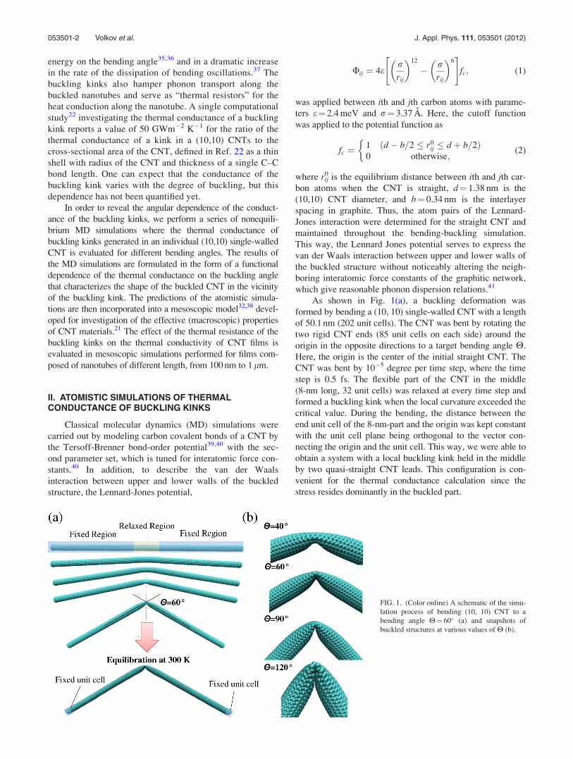
As shown in Fig. 1(a), a buckling deformation was
formed by bending a (10, 10) single-walled CNT with a length
of 50.1 nm (202 unit cells). The CNT was bent by rotating the
two rigid CNT ends (85 unit cells on each side) around the
origin in the opposite directions to a target bending angle H.
Here, the origin is the center of the initial straight CNT. The
CNT was bent by 10�5 degree per time step, where the time
step is 0.5 fs. The flexible part of the CNT in the middle
(8-nm long, 32 unit cells) was relaxed at every time step and
formed a buckling kink when the local curvature exceeded the
critical value. During the bending, the distance between the
end unit cell of the 8-nm-part and the origin was kept constant
with the unit cell plane being orthogonal to the vector con-
necting the origin and the unit cell. This way, we were able to
obtain a system with a local buckling kink held in the middle
by two quasi-straight CNT leads. This configuration is con-
venient for the thermal conductance calculation since the
stress resides dominantly in the buckled part.
FIG. 1. (Color online) A schematic of the simu-
lation process of bending (10, 10) CNT to a
bending angle H¼ 60� (a) and snapshots of
buckled structures at various values of H (b).
053501-2 Volkov et al. J. Appl. Phys. 111, 053501 (2012)
The bending simulations were performed for different
bending angles H. After the bending simulation, as illus-
trated in Fig. 1(a), the buckled CNT was equilibrated at
300 K with only one unit cell at each end fixed. As shown in
Fig. 1(b), the resulting buckled structures were subjected to
local distortions that increased with H. After the equilibra-
tion, the quasi-straight parts of the CNTs deformed slightly
to balance the stress at the buckled structures in the direction
tangential to the fixed unit cells at the ends. Since the follow-
ing mesoscopic simulations required the local angle at the
buckling kink rather than the bending angle, the buckling
angle33 v was defined and calculated as follows.
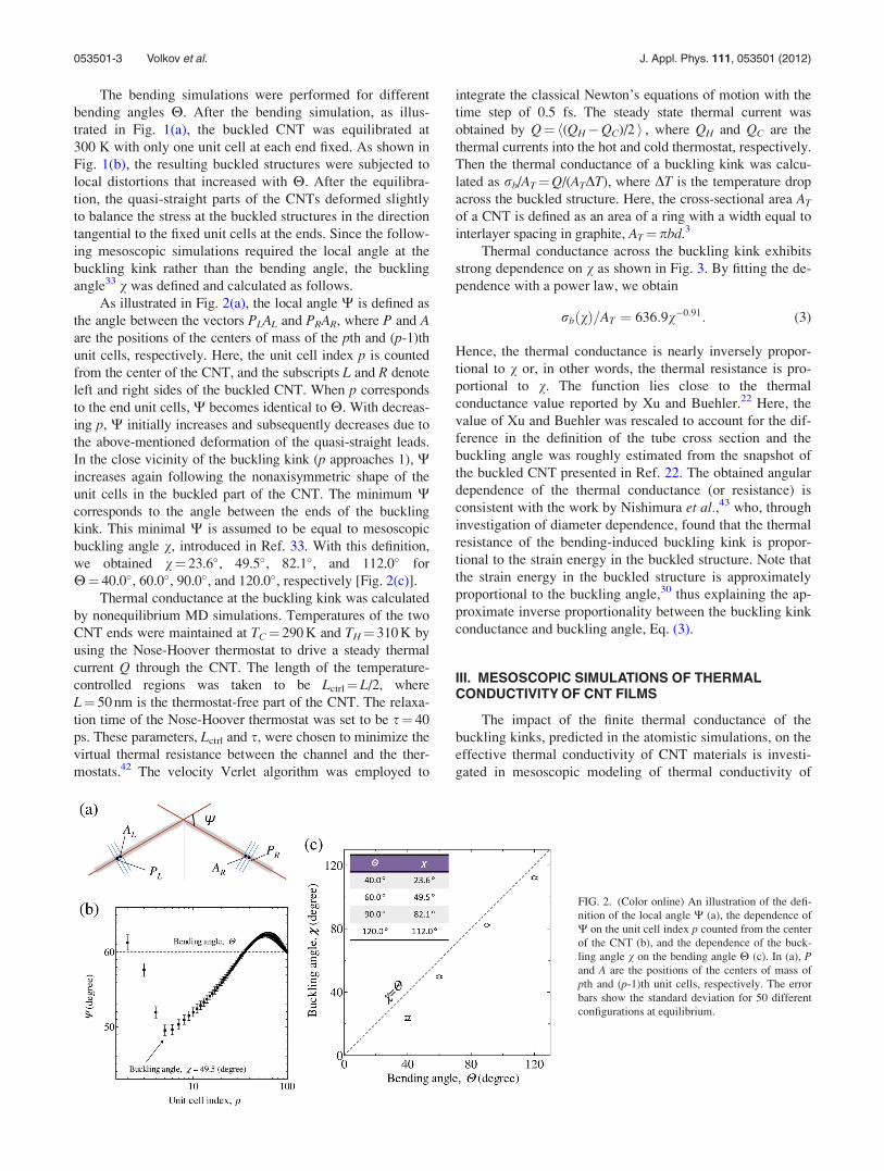
As illustrated in Fig. 2(a), the local angle W is defined as
the angle between the vectors PLAL and PRAR, where P and Aare the positions of the centers of mass of the pth and (p-1)th
unit cells, respectively. Here, the unit cell index p is counted
from the center of the CNT, and the subscripts L and R denote
left and right sides of the buckled CNT. When p corresponds
to the end unit cells, W becomes identical to H. With decreas-
ing p, W initially increases and subsequently decreases due to
the above-mentioned deformation of the quasi-straight leads.
In the close vicinity of the buckling kink (p approaches 1), Wincreases again following the nonaxisymmetric shape of the
unit cells in the buckled part of the CNT. The minimum Wcorresponds to the angle between the ends of the buckling
kink. This minimal W is assumed to be equal to mesoscopic
buckling angle v, introduced in Ref. 33. With this definition,
we obtained v¼ 23.6�, 49.5�, 82.1�, and 112.0� for
H¼ 40.0�, 60.0�, 90.0�, and 120.0�, respectively [Fig. 2(c)].
Thermal conductance at the buckling kink was calculated
by nonequilibrium MD simulations. Temperatures of the two
CNT ends were maintained at TC¼ 290 K and TH¼ 310 K by
using the Nose-Hoover thermostat to drive a steady thermal
current Q through the CNT. The length of the temperature-
controlled regions was taken to be Lctrl¼L/2, where
L¼ 50 nm is the thermostat-free part of the CNT. The relaxa-
tion time of the Nose-Hoover thermostat was set to be s¼ 40
ps. These parameters, Lctrl and s, were chosen to minimize the
virtual thermal resistance between the channel and the ther-
mostats.42 The velocity Verlet algorithm was employed to
integrate the classical Newton’s equations of motion with the
time step of 0.5 fs. The steady state thermal current was
obtained by Q¼h(QH�QC)/2 i , where QH and QC are the
thermal currents into the hot and cold thermostat, respectively.
Then the thermal conductance of a buckling kink was calcu-
lated as rb/AT¼Q/(ATDT), where DT is the temperature drop
across the buckled structure. Here, the cross-sectional area AT
of a CNT is defined as an area of a ring with a width equal to
interlayer spacing in graphite, AT¼ pbd.3
Thermal conductance across the buckling kink exhibits
strong dependence on v as shown in Fig. 3. By fitting the de-
pendence with a power law, we obtain
rbðvÞ=AT ¼ 636:9v�0:91: (3)
Hence, the thermal conductance is nearly inversely propor-
tional to v or, in other words, the thermal resistance is pro-
portional to v. The function lies close to the thermal
conductance value reported by Xu and Buehler.22 Here, the
value of Xu and Buehler was rescaled to account for the dif-
ference in the definition of the tube cross section and the
buckling angle was roughly estimated from the snapshot of
the buckled CNT presented in Ref. 22. The obtained angular
dependence of the thermal conductance (or resistance) is
consistent with the work by Nishimura et al.,43 who, through
investigation of diameter dependence, found that the thermal
resistance of the bending-induced buckling kink is propor-
tional to the strain energy in the buckled structure. Note that
the strain energy in the buckled structure is approximately
proportional to the buckling angle,30 thus explaining the ap-
proximate inverse proportionality between the buckling kink
conductance and buckling angle, Eq. (3).
III. MESOSCOPIC SIMULATIONS OF THERMALCONDUCTIVITY OF CNT FILMS
The impact of the finite thermal conductance of the
buckling kinks, predicted in the atomistic simulations, on the
effective thermal conductivity of CNT materials is investi-
gated in mesoscopic modeling of thermal conductivity of
FIG. 2. (Color online) An illustration of the defi-
nition of the local angle W (a), the dependence of
W on the unit cell index p counted from the center
of the CNT (b), and the dependence of the buck-
ling angle v on the bending angle H (c). In (a), Pand A are the positions of the centers of mass of
pth and (p-1)th unit cells, respectively. The error
bars show the standard deviation for 50 different
configurations at equilibrium.
053501-3 Volkov et al. J. Appl. Phys. 111, 053501 (2012)

CNT films. The basic principles of the dynamic mesoscopic
model that enables computationally efficient simulations of
self-organization of thousands of CNTs into continuous net-
works of bundles are briefly outlined first, in Sec. III A. The
structure of CNT films is analyzed in Sec. III B and the
method used for the evaluation of the thermal conductivity
of the films is described in Sec. III C. The results of the cal-
culations of thermal conductivity of the CNT films per-
formed with both constant and buckling-angle-dependent
values of the thermal conductance of the buckling kinks are
presented in Sec. III D.
A. Mesoscopic modeling of the formation of CNTnetwork materials
The mesoscopic model for simulation of CNT-based
materials adopts a coarse-grained representation of individ-
ual CNTs as chains of stretchable cylindrical segments.38
Each CNT i is defined by positions ri;j of nodes j jointing the
neighboring segments and local internal temperatures at the
nodes, Ti;j, as shown in Fig. 4(a). The dynamics of a system
of interacting CNTs is described by solving the equations of
motion of classical mechanics for the positions of all nodes.
The forces acting on the nodes are calculated based on the
mesoscopic force field that includes terms describing internal
stretching, bending, and buckling of nanotubes,33,38 the van
der Waals interactions among the CNTs,32 and the interac-
tions with external bodies.
The bending buckling of a CNT is assumed to occur at
mesoscopic nodes where the local radius of curvature
reaches its critical value of 27.5 nm chosen to be within the
range of values predicted in quasi-static MD simulations of
(10,10) CNTs.33 In the post-buckling state, the bending
energy of a part of the nanotube represented by mesoscopic
segments attached to the node where the buckling occurs is
described by an energy term that is proportional to the buck-
ling angle, vij, Fig. 4(a). The switch from the quadratic de-
pendence on the local curvature to the linear dependence on
the buckling angle represents the effective softening of the
bending potential upon buckling, which is predicted in atom-
istic simulations.35,36 In order to verify the agreement
between the atomistic and mesoscopic models adopted in the
present work, the buckling angle was calculated with the
mesoscopic model applied to an individual buckled nanotube
with the same computational setup used in the atomistic sim-
ulations and described in Section II. For the same bending
conditions, the deviation of the buckling angles vij predicted
by the mesoscopic model from the ones computed in atomis-
tic simulations is found to not exceed 10% for the range of
angles shown in Fig. 3.
The mesoscopic model briefly described above is used
to generate samples of CNT films with continuous network
structures typical for real CNT materials.32,33 The dynamic
mesoscopic simulations are performed for films consisting of
(10,10) single walled CNTs with length LT varying from
100 nm to 1 lm. The films have thickness of 100 nm and ma-
terial density of 0.2 g cm�3, which is a typical density of
CNT films and buckypaper.25 Several simulations are also
performed for films with a smaller thickness of 20 nm and
only a relatively small difference from 100 nm films (below
18%) is found in the values of in-plane thermal conductivity.
The initial samples used in the simulations are generated by
stacking planar layers of randomly oriented and distributed
straight nanotubes with a distance between the layers chosen
to ensure interlayer interaction. The periodic boundary con-
ditions are applied in the directions parallel to the film surfa-
ces. The film density is maintained at a constant value by
two planes enclosing the film from the two sides normal to
the film surfaces and interacting with CNTs by a short-range
repulsive potential. The equilibrium length of segments in
the mesoscopic representation of CNTs is chosen to be 2 nm,
more than an order of magnitude smaller than the critical
FIG. 3. (Color online) The dependence of the thermal conductance of the
bending buckling kink rb=AT on the buckling angle v predicted for (10,10)
CNTs in atomistic simulations. Square symbols show the values found in at-
omistic simulations performed in the present work and the triangle symbol
shows the value recalculated from Ref. 22. Solid curve represents a power
law fit to the data points given by Eq. (3).
FIG. 4. (Color online) Schematic sketch of the mesoscopic representation of
a nanotube i as a chain of cylindrical segments defined by nodes j (a) and the
distribution of temperature along the nanotube in the vicinity of the buckling
kink (b). The solid circles show the mesoscopic nodes, with nodes where
buckling occurs colored red. In the mesoscopic model, the buckling angle vij
is defined as an angle between axes of segments adjacent to the buckling
kink. Buckling kinks and CNT ends divide the nanotubes into several
buckling-free parts. Temperature is assumed to be constant within any
buckling-free part of the nanotube and exhibits a jump at buckling kinks.
053501-4 Volkov et al. J. Appl. Phys. 111, 053501 (2012)

radius of curvature for the onset of bending buckling in
(10,10) CNTs.
Each dynamic simulation consists of a 1 ns long constant
energy part characterized by a rapid spontaneous self-
assembly of CNTs into continuous networks of bundles, fol-
lowed by a longer 9 – 15 ns part performed under conditions
of constant 300 K temperature and characterized by slower
evolution and eventual stabilization of the network struc-
tures.32,33 The films with stable network structures of inter-
connected CNT bundles are produced for nanotubes with
length of 150, 200, 400, and 1000 nm. A system of CNTs
with length of 100 nm, which is below the critical length
needed for the formation of a stable network of bundles at
room temperature,33 is also considered in the simulations.
This system has a cellular structures composed of CNT bun-
dles weakly connected with each other. While all of these
films are used in the analysis of the CNT length dependence
of the thermal conductivity presented in Sec. III D, two of
the samples are selected for a more detailed investigation of
the factors that control the heat conduction in the network
structures. These are the films with LT ¼ 200 nm and dimen-
sions of 500� 500� 100 nm3 (sample A) and LT ¼ 1000 nm
and dimensions 2000� 2000� 100 nm3 (sample B).
B. Structure of CNT films
The continuous random networks of CNT bundles with
partial hexagonal ordering of individual CNTs in the bundles,
generated in the dynamic mesoscopic simulations, are visually
similar to the structures observed in experimental images of
surfaces of CNT films or “buckypaper.”24–29 In particular, the
partial hexagonal ordering of individual CNTs in the bundles
and the presence of multiple interconnections between bun-
dles formed by CNTs that belong to two or more bundles
simultaneously have been identified in experimental images
of CNT films.24–29 The size distributions of the CNT bundles
and other structural characteristics of the network structures
are determined by the length of the nanotubes and the proce-
dure of the sample preparation (the duration of the constant
energy stage of the dynamic simulations, see Sec. III A). In
particular, the average number of CNTs in a bundle cross sec-
tion is equal to 25.7 in sample A and 32.2 in sample B, while
the mean-square deviation of the number of CNTs in a bundle
cross section is close to 25 in both cases.
Both the fraction of buckled nanotubes fb in the simu-
lated samples and the average number of buckling kinks per
buckled nanotube hNbi increase with increasing length of the
CNTs and are fb ¼ 0:37, hNbi¼ 1.9 in sample A and
fb ¼ 0:9, hNbi¼ 5 in sample B, Fig. 5(a). The average num-
ber of buckling kinks per unit length of a CNT, hNbifb=LT ,
has a weak dependence on the CNT length and is equal to
3:7 lm�1 in sample A and 4:5 lm�1 in sample B. The buck-
ling kinks are distributed unevenly along the CNTs, with
pairs or triples of buckling kinks often located close to each
other, Fig. 5(b).
The mesoscopic samples can be described as networks
of endless bundles that split into sub-bundles or individual
CNTs, with the sub-bundles tangling and merging again into
thicker bundles. The buckling kinks are mostly located in
parts of nanotubes that belong to interconnections between
thicker bundles, as can be seen in Fig. 5(b). The interconnec-
tions may consist of individual CNTs, but are more often
(especially for samples composed of longer CNTs) repre-
sented by thinner sub-bundles that connect thicker ones. In
sample A, which is composed of relatively short CNTs, most
nanotubes belong to one or two bundles only and, thus, one
can clearly distinguish nanotubes that serve as interconnec-
tions between bundles. Many of such interconnections are
buckled. In samples with longer CNTs, most of the CNTs
have multiple buckling kinks and simultaneously belong to
several bundles. The buckling kinks in these cases are con-
centrated within thinner bundles that serve as interconnec-
tions between the thicker parts of the continuous network
structure. Moreover, many CNTs that belong to the same
interconnecting bundle tend to have buckling kinks located
in a close proximity from each other.
Thus, in samples composed of sufficiently long nano-
tubes, most of the CNTs have multiple buckling kinks that
tend to concentrate in thinner bundles serving as interconnec-
tions between the thicker bundles. The interconnections can
be expected to play an important role in the heat conduction
through the network structure, suggesting that the effect of
the finite conductance of the buckling kinks may be amplified
by the preferential buckling of the interconnections. On the
other hand, as shown in Ref. 33, the statistical distribution of
the buckling angles v in samples with LT > 120 nm, when
the stable network of bundles is formed, is characterized by a
large number of kinks with small v. In particular, in both
sample A and sample B, v is less than 20� in more than 90%
of the buckling kinks. Due to the strong dependence of rb on
v (see Fig. 3) and broad distributions of the buckling angles
in the network structures, the quantitative effect of bending
buckling on the thermal conductivity of the CNT materials is
difficult to assess without direct numerical simulation of the
heat flow in the mesoscopic samples.
C. Method of calculation of thermal conductivity ofmesoscopic samples
The calculation of in-plane thermal conductivity k of the
CNT films is performed with a method suggested in Ref. 21
and enhanced here with treatment of finite thermal conduct-
ance of the buckling kinks. Briefly, the thermal conductivity
is calculated by applying a temperature gradient to a static
network structure generated in a mesoscopic dynamic simu-
lation, evaluating a steady-state heat flux through the sample,
and finding the thermal conductivity from the Fourier law.
The temperature gradient is created in a mesoscopic sam-
ple by disabling the periodic boundary conditions in the xdirection and cutting the CNTs that cross left-hand and right-
hand sides of the sample, so that the parts of such CNTs are
considered as individual nanotubes in the calculations of ther-
mal conductivity. The mesoscopic nodes in parts of the cut
nanotubes bounded by a cut segment and a buckling kink (or
CNT end if no buckling kinks are present) are assigned con-
stant temperatures Thot and Tcold at the left-hand and right-
hand sides of the sample, respectively (Fig. 6). In rare cases
when the same CNT crosses the left-hand or right-hand sides
053501-5 Volkov et al. J. Appl. Phys. 111, 053501 (2012)

of the sample more than once, the constant temperatures are
also maintained for buckling-free parts of the nanotube
bounded by the two cut segments. The temperatures at all
nodes of all “internal” CNTs are then calculated from the bal-
ance of incoming and outgoing heat fluxes. The analysis is
performed under the assumption that k is defined by the ther-
mal resistance of the inter-tube contacts14,17,21 and buckling
kinks, whereas the intrinsic thermal resistance of individual
non-buckled CNTs is neglected. That is, in a buckling kink
associated with node j of nanotube i, the temperature jumps
from a “left-hand side” value Ti;jðLÞ to a “right-hand side”
value Ti;jðRÞ [Fig. 4(b)] due to the finite thermal resistance of
the buckling kink, whereas in nodes representing buckling-
free parts of the nanotube, Ti;jðLÞ ¼ Ti;jðRÞ ¼ Ti;j. With this
assumption, the temperature of any buckling-free part of a
nanotube, which in bounded by a CNT end and/or buckling
kink(s), is constant and can be calculated from an equation
expressing the balance of all incoming and outgoing heat
fluxes for this part of the CNT. In particular, for a part of
nanotube i bounded by buckling kinks at nodes M and N, this
equation can be written as
Qbði;MÞ � Qbði;NÞ þXN�1
j¼M
XNT
k¼1
XNk�1
m¼1
Qcði;jÞ�ðk;mÞ ¼ 0; (4)
where NT is the total number of nanotubes in the sample,
Nk is the number of mesoscopic nodes in nanotube k,
Qbði;jÞ ¼ rbði;jÞðTi;jðLÞ � Ti;jðRÞÞ is the heat flux through
the buckling kink in node j of nanotube i, and Qcði; jÞ�ðk;mÞ¼ rcði;jÞ�ðk;mÞðTi;jðRÞ � Tk;mðRÞÞ is the contact heat flux
between a pair of mesoscopic segments defined by nodes
j and jþ 1 of nanotube i and nodes m and mþ 1 of nano-
tube k. The thermal conductance of a buckling kink is a
function of the buckling angle, rbði;jÞ ¼ rbðvi;jÞ given by
Eq. (3), and the contact thermal conductance for a pair of
interacting mesoscopic segments, rcði;jÞ�ðk;mÞ, is calculated
as follows:21
rcði;jÞ�ðk;mÞ ¼ rc0
Wði;jÞ�ðk;mÞW0
;
Wði;jÞ�ðk;mÞ ¼ n2r
ðSði;jÞ
ðSðk;mÞ
wðrÞdSðk;mÞdSði;jÞ;(5)
where the integration is performed over the surfaces of the
interacting segments, r is the distance between points on
surfaces of different segments, wðrÞ is a “heat transfer” func-
tion21 that vanishes for atomic pairs with r > rc (rc ¼ 10:2 A
is the cutoff distance of the carbon-carbon interatomic poten-
tial for nonbonded interactions), W0 is a value of Wði;jÞ�ðk;mÞfor a geometrical arrangement of segments for which the
conductance is known and equal to rc0, and nr is the surface
number density of carbon atoms in the CNT. This method
accounts for a continuous transition between the limiting
FIG. 6. (Color online) Steady-state temperature distribution established in a
mesoscopic sample A and used in the calculation of the thermal conductivity of
the network structure. The sample has dimensions of 500� 500� 100 nm3 and
is composed of 7829 (10,10) CNTs with LT ¼ 200 nm and material density of
0.2 g cm�3. The nanotubes are colored by their temperature. The temperature
distribution is shown for rb ¼ 1, but it is visually indistinguishable from the
one calculated with rb ¼ 0.
FIG. 5. (Color online) Fraction of nanotubes with a given number of buckling kinks, Nb, in samples A (red open squares) and B (green open circles) (a) and a
part of sample A shown in Fig. 6 with positions of buckling kinks marked by dark (red online) color (b). The average number of buckling kinks per buckled nano-
tube, hNbi, and the fraction of buckled nanotubes, fb, are marked in (a) by the solid red square and green circle for samples A and B, respectively.
053501-6 Volkov et al. J. Appl. Phys. 111, 053501 (2012)

cases of parallel and perpendicular CNTs that have been
investigated in MD simulations14–19 and experiments.20 For
(10,10) CNTs, the model given by Eq. (5) is parameterized
by the value rc0 ¼ 5� 10�11 WK�1 found in atomistic
Green’s function calculations for two CNTs crossing each
other at a 90� angle.14
For buckling-free parts of CNTs bounded from one or
both sides by the end(s) of the nanotube (i.e. when nodes Mand/or N coincide with the end(s) of the CNT) the corre-
sponding heat fluxes Qbði;MÞ and/or Qbði;NÞ are set to zero in
Eq. (4). The heat balance equation is not solved for
buckling-free parts of CNTs that are crossing the left-hand
and right-hand sides of the sample; rather, the temperatures
of all segments in these parts are fixed at the corresponding
values of Thot or Tcold.
The heat flux Qx through any cross-section of the sample
that is perpendicular to the x axis can be calculated, e.g., by
evaluating the total contact heat fluxes QxðcoldÞ and QxðhotÞ for
CNTs that are crossing the left-hand and right-hand sides of
the sample:
QxðhotÞ ¼XNT
i¼1
XNi�1
j¼1
diðhotÞXNT
k¼1
XNk�1
m¼1
Qcði;jÞ�ðk;mÞ;
QxðcoldÞ ¼ �XNT
i¼1
XNi�1
j¼1
diðcoldÞXNT
k¼1
XNk�1
m¼1
Qcði;jÞ�ðk;mÞ;
(6)
where diðhotÞ (diðcoldÞ) is equal to unity if CNT i crosses the
left (right)-hand sides of the sample and is equal to zero
otherwise. The heat flux Qx ¼ QxðcoldÞ ¼ QxðhotÞ is deter-
mined by solving a linear system of equations given for
all buckling-free parts of the CNTs by Eq. (4). The equa-
tions are solved for the nodal temperatures iteratively by
the Gauss-Seidel method,44 until the condition 2jQxðcoldÞ�QxðhotÞj=ðQxðcoldÞ þ QxðhotÞÞ < 10�6 is satisfied.
Once the heat flux Qx and nodal temperatures of all
“internal” nanotubes in the sample are calculated, the tem-
perature gradient in the x direction, rTx, is evaluated for the
central part of the sample, where the distribution of the tem-
perature is linear. The temperature gradient rTx is not equal
to the imposed value ðTcold � ThotÞ=Lx (Lx is the length of the
sample along the x axis) since the presence of CNT segments
maintained at constant temperatures Thot and Tcold results in
a non-linear distribution of the average material temperature
in the vicinities of the constant temperature sides of the sam-
ple. Finally, the in-plane thermal conductivity of the film is
calculated based on the Fourier law, k ¼ �Qx=ðAxrTxÞ,where Ax is the area of the sample cross section in the direc-
tion perpendicular to the x axis. Since neither rbði;jÞ nor
rcði;jÞ�ðk;mÞ in Eq. (4) depends on temperature, the calculated
values of k do not depends on the choice of Tcold and Thot
used in the calculations. The temperatures of Tcold¼ 300 K
and Thot¼ 600 K are specified in Fig. 6 for visualization pur-
poses only.
D. Thermal conductivity of CNT films
In order to reveal general trends in variation of the
thermal conductivity of CNT films due to the finite thermal
resistance of buckling kinks, the calculations of thermal
conductivity were performed for both constant values of the
conductance, rb=AT ¼ const, that spans the range from 0 to
50 GWm�2 K�1 and variable angular-dependent conduct-
ance, rbðvÞ, defined by Eq. (3). The results of the calcula-
tions are related to the data obtained in Ref. 21 under
conditions of zero thermal resistance of the buckling kinks
(rb ¼ 1).
The effect of the finite values of the thermal conduct-
ance of the buckling kinks on the temperature distribution in
the CNT films is found to be fairly weak in all calculations,
regardless of the assumed value of rb. Although the calcula-
tions based on Eq. (4) assume an abrupt temperature change
at any of the buckling kinks, the actual differences,
Ti;jðLÞ � Ti;jðRÞ, appear to be relatively small even for rb ¼ 0,
which corresponds to buckling kinks acting as perfect ther-
mal insulators. For instance, the temperature distribution cal-
culated for sample A under the assumption of zero thermal
resistance of the buckling kinks (rb ¼ 1) and shown in
Fig. 6 is visually indistinguishable from the one calculated
under the assumption of thermally insulating kinks (rb ¼ 0)
when the temperature scale adopted in Fig. 6 is used.
Despite the relatively weak effect on the temperature of
individual CNTs, the finite thermal conductance of the buck-
ling kinks results in non-negligible changes in the thermal
conductivity of the CNT films. The results of the calculations
performed with constant (angular-independent) values of the
thermal conductance are shown for samples A and B in
Fig. 7. For the range of values of rb considered in this work,
the ratio of thermal conductivity k to the conductivity k0,
predicted for zero thermal resistance of the buckling kinks, is
substantially smaller than unity, particularly in the case of
sample B composed of longer CNTs. The thermal conductiv-
ity k increases with increasing rb, but remains 4%
and 29% below k0 for samples A and B, respectively, at
rb=AT ¼ 50 GWm�2 K�1.
FIG. 7. (Color online) Ratio of thermal conductivity k calculated for different
values of constant conductance of buckling kinks (rb=AT ¼ const.) to the
thermal conductivity k0 calculated with zero thermal resistance of buckling
kinks (rb ¼ 1). The results are shown for samples A (LT ¼ 200 nm; red
squares and solid curve) and B (LT ¼ 1000 nm; green circle and dashed
curve).
053501-7 Volkov et al. J. Appl. Phys. 111, 053501 (2012)

The values of k=k0 obtained with rb ¼ 0 are equal to
0.66 and 0.31 for samples A and B, respectively. These val-
ues represent the lower bound estimates of the conductivity
for an arbitrary rbðvÞ dependence. The decrease of the film
conductivity due to the presence of the insulating buckling
kinks with rb ¼ 0 has the same physical origin as the
decrease in the conductivity with decreasing CNT length. A
quadratic scaling of the thermal conductivity has been
derived analytically for random networks of straight
CNTs in which the thermal transport is controlled by the
inter-tube contact resistance, while a similar superquadratic
dependence (k0 / L2:2T ) is found for the networks of bundles
considered in the present work under condition of
rb ¼ 1.21 The quadratic scaling, however, cannot be
directly applied for the evaluation of the thermal conductiv-
ity in a film where the average length of CNTs is reduced to
LT=ðhNbifbÞ by the virtual cuts at the buckling kinks with
rb ¼ 0. For example, hNbifb � 4:5 for sample B and, hence,
the expected ratio of the conductivities based on the quad-
ratic scaling law k0 / L2T would be k=k0 � 0:05. The actual
value of k=k0 calculated with rb ¼ 0 is substantially larger,
k=k0 � 0:31. The reason for this discrepancy is in a highly
uneven distribution of buckling kinks in the CNT films,
with buckling kinks concentrating in bundles serving as
interconnections in the network structures. Moreover, the
scaling laws are derived in Ref. 21 for fixed (rather than av-
erage) length of the CNTs and should be modified for a
given length distribution. It is worth noting that in a case
when every nanotube in the sample B is virtually cut into
two equal parts and the thermal resistance of the buckling
kinks is neglected, the mesosopic simulation predicts
roughly four-fold decrease in k0 in agreement with the
quadratic scaling law.
The preferential buckling of CNTs that belong to thin
bundles serving as interconnections between thicker bundles,
revealed in the structural analysis discussed in Sec. III B,
suggests that the effect of buckling on the thermal conductiv-
ity of the films is largely defined by the role the interconnects
play in the heat conduction through the network structures.
In order to characterize the contribution of different types of
structural elements of the networks to the overall heat
conduction in a CNT film, we calculate the sum of absolute
values of the contact heat fluxes for a given CNT i:
QRðiÞ ¼XNi�1
j¼1
XNT
k¼1
XNk�1
m¼1
jQcði;jÞ�ðk;mÞj; (7)
which is hereafter is referred to as the “total heat flux sum.”
A large value of QRðiÞ indicates that nanotube i is an impor-
tant channel of the heat conduction through the network and,
therefore, QRðiÞ can be used as a rough measure of the
involvement of individual CNTs into the overall heat con-
duction process in the material.
The visual pictures of the distributions of QRðiÞ in the
network structures, e.g., Fig. 8, are fairly complex, but still
provide opportunities for making a number of important
observations. In the calculations performed with zero ther-
mal resistance of the buckling kinks [Fig. 8(a)], thick bun-
dles, such as a bundle marked by BB, are composed of CNTs
with relatively small QRðiÞ, while much larger values of QRðiÞare characteristic for individual CNTs, thin bundles that
serve as interconnections, and thick bundles that split into
many sub-bundles, such as a bundle marked by AA. Turning
the buckled segments of CNTs to thermal insulators by
assuming rb ¼ 0 makes almost no visible impact on the
values of QRðiÞ in thick bundles such as the BB one, but sig-
nificantly reduces QRðiÞ in thin bundles and split bundles
such as the AA one [Fig. 8(b)]. These qualitative observa-
tions highlight the importance of the preferential buckling of
the interconnections between bundles in defining the impact
of the finite conductance of the buckling kinks on the ther-
mal conductivity of the CNT materials.
In order to quantify the special role of the buckled inter-
connections in the overall heat conduction, the values of the
FIG. 8. (Color online) A part of sample A shown in Fig. 6 with nanotubes colored by their total heat flux sum QRðiÞ, Eq. (7), calculated with rb ¼ 1 (a) and
rb ¼ 0 (b). AA and BB mark two characteristic bundles of CNTs. Bundle AA splits into many thinner bundles and includes multiple buckled CNTs. As a result,
the values of QRðiÞ for nanotubes in this bundle are visibly different in panels (a) and (b). Bundle BB mostly consists of nonbuckled CNTs, and the values of
QRðiÞ for nanotubes in this bundle exhibit only small difference between panels (a) and (b).
053501-8 Volkov et al. J. Appl. Phys. 111, 053501 (2012)
total heat flux sum are averaged over nanotubes with the
same number of buckling kinks, Nb, and the dependence of
the average quantities hQRi on Nb are shown for sample B in
Fig. 9. The values of hQRi calculated with rb ¼ 1 increase
with increasing Nb, indicating that CNTs that contain a larger
number of buckling kinks are, on average, more active par-
ticipants of the heat conduction than CNTs with smaller
number of buckling kinks. As discussed in Sec. III B, the
CNTs with large numbers of buckling kinks are also the ones
that buildup the interconnections in the network structures of
the films. It is not surprising, then, that when the buckling
kinks are assumed to be thermally insulating (rb ¼ 0), an op-
posite trend of hQRi decreasing with Nb is observed. In this
case, the maximum hQRi corresponds to buckling-free
CNTs, because all other CNTs are virtually cut and cannot
efficiently participate in the heat conduction. It is remark-
able, though, that the presence of thermally insulating
buckling kinks significantly reduces hQRi even for the
buckling-free CNTs. The dependences of hQRi on Nb in sam-
ple A with much shorter CNTs is qualitatively similar to the
ones shown in Fig. 9.
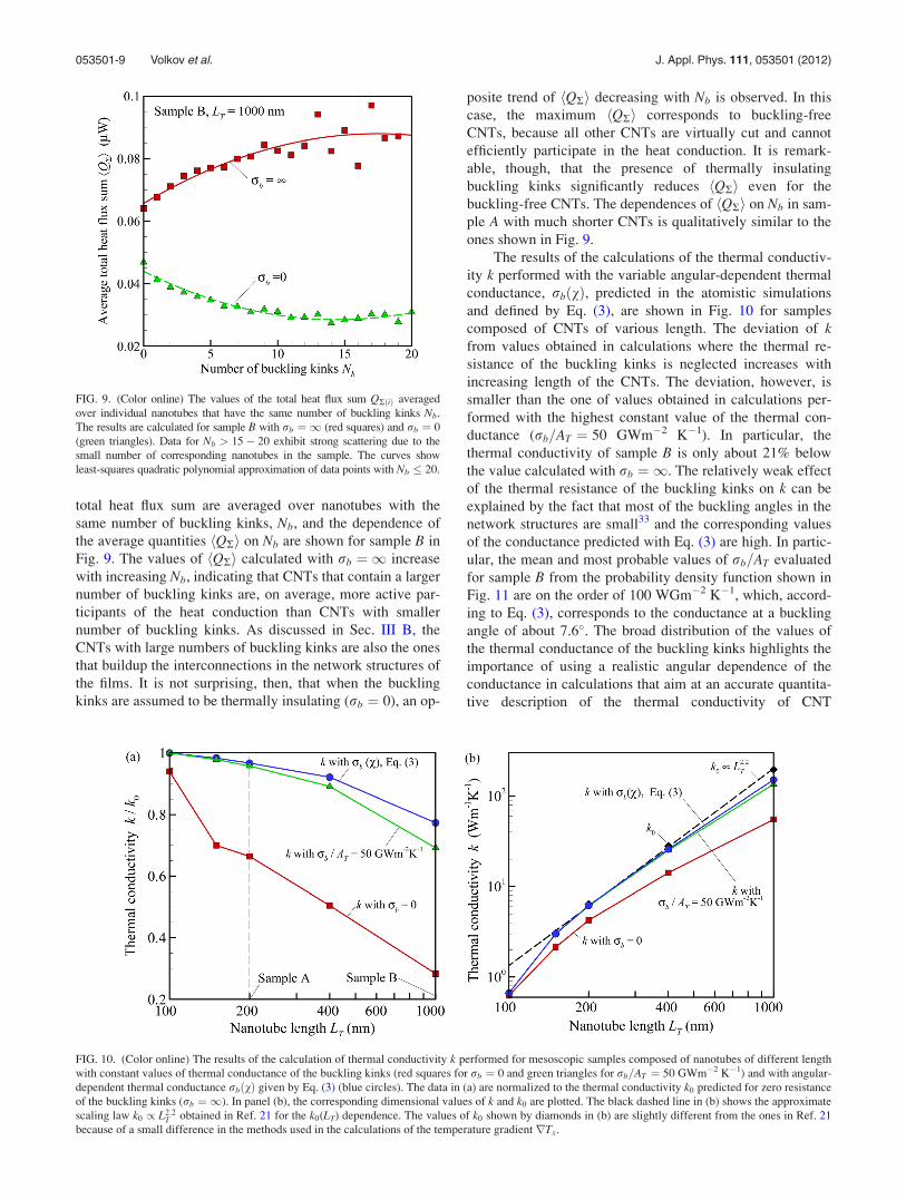
The results of the calculations of the thermal conductiv-
ity k performed with the variable angular-dependent thermal
conductance, rbðvÞ, predicted in the atomistic simulations
and defined by Eq. (3), are shown in Fig. 10 for samples
composed of CNTs of various length. The deviation of kfrom values obtained in calculations where the thermal re-
sistance of the buckling kinks is neglected increases with
increasing length of the CNTs. The deviation, however, is
smaller than the one of values obtained in calculations per-
formed with the highest constant value of the thermal con-
ductance (rb=AT ¼ 50 GWm�2 K�1). In particular, the
thermal conductivity of sample B is only about 21% below
the value calculated with rb ¼ 1. The relatively weak effect
of the thermal resistance of the buckling kinks on k can be
explained by the fact that most of the buckling angles in the
network structures are small33 and the corresponding values
of the conductance predicted with Eq. (3) are high. In partic-
ular, the mean and most probable values of rb=AT evaluated
for sample B from the probability density function shown in
Fig. 11 are on the order of 100 WGm�2 K�1, which, accord-
ing to Eq. (3), corresponds to the conductance at a buckling
angle of about 7.6�. The broad distribution of the values of
the thermal conductance of the buckling kinks highlights the
importance of using a realistic angular dependence of the
conductance in calculations that aim at an accurate quantita-
tive description of the thermal conductivity of CNT
FIG. 9. (Color online) The values of the total heat flux sum QRðiÞ averaged
over individual nanotubes that have the same number of buckling kinks Nb.
The results are calculated for sample B with rb ¼ 1 (red squares) and rb ¼ 0
(green triangles). Data for Nb > 15� 20 exhibit strong scattering due to the
small number of corresponding nanotubes in the sample. The curves show
least-squares quadratic polynomial approximation of data points with Nb � 20.
FIG. 10. (Color online) The results of the calculation of thermal conductivity k performed for mesoscopic samples composed of nanotubes of different length
with constant values of thermal conductance of the buckling kinks (red squares for rb ¼ 0 and green triangles for rb=AT ¼ 50 GWm�2 K�1) and with angular-
dependent thermal conductance rbðvÞ given by Eq. (3) (blue circles). The data in (a) are normalized to the thermal conductivity k0 predicted for zero resistance
of the buckling kinks (rb ¼ 1). In panel (b), the corresponding dimensional values of k and k0 are plotted. The black dashed line in (b) shows the approximate
scaling law k0 / L2:2T obtained in Ref. 21 for the k0(LT) dependence. The values of k0 shown by diamonds in (b) are slightly different from the ones in Ref. 21
because of a small difference in the methods used in the calculations of the temperature gradient rTx.
053501-9 Volkov et al. J. Appl. Phys. 111, 053501 (2012)

materials. The effect of the buckling kinks increases with
increasing length of the nanotubes. For longer CNTs, how-
ever, the increasing contribution of the intrinsic thermal re-
sistance of the nanotubes, not included in the present
mesoscopic calculations, may overshadow the contribution
of the buckling kinks. Indeed, the reduction of the thermal
conductivity of the films as a result of the inclusion of the fi-
nite intrinsic conductivity of the CNTs is found to be larger
than the reduction due to the buckling kinks [with angular-
dependent conductance of Eq. (3)] for all samples considered
in the mesoscopic calculations even if a relatively large
intrinsic conductivity of 2000 Wm�1 K�1 is assumed in the
calculations.
IV. SUMMARY
The results of non-equilibrium molecular dynamics sim-
ulations of heat conduction in (10,10) single-walled carbon
nanotubes reveal a strong dependence of the thermal con-
ductance of a buckling kink rb on the buckling angle. For a
range of buckling angles from 20� to 110� the values of
rb=AT vary from 40 to 10 GWm�2 K�1 which agree by the
order of magnitude with the value reported in an earlier
study.22 The implications of the finite thermal conductance
of the buckling kinks on the conductivity of CNT-based
materials are investigated in mesoscopic calculations per-
formed for CNT films composed of thousands of CNTs
arranged into continuous networks of bundles. The meso-
scopic calculations are performed for several constant values
of the thermal conductance of the buckling kinks, as well as
for the angular-dependent conductance predicted in the at-
omistic simulations. The results of the calculations suggest
that the buckling kinks make a moderate, but not negligible,
contribution to the thermal conductivity of CNT-based mate-
rials and the account for the angular dependence of the ther-
mal conductance of the buckling kinks is essential for
accurate quantitative evaluation of the thermal conductivity.
The effect of the finite buckling conductance on the thermal
conductivity of the network structures is amplified by the
preferential buckling of thin bundles and individual CNTs
serving as interconnections between thicker bundles in the
network structures. The total heat flux passing through the
CNTs that are parts of the interconnections is, on average,
higher than in other parts of the network structures. Conse-
quently, the high concentration of the buckling kinks in
interconnects results in a stronger impact of the buckling on
the overall thermal conductivity of the films. The effect of
the buckling kinks on the thermal conductivity of the CNT
films increases with increasing length of the nanotubes and
accounts for about 20% reduction of the conductivity of a
film composed of 1 lm long CNTs. The method developed
in this work for the investigation of the effect of buckling
kinks on the heat conduction in CNT materials can be readily
extended to systems with various types of structural imper-
fections that can be described in terms of the effective
“conductance” of the defected CNT regions.
ACKNOWLEDGMENTS
A.N.V., D.N., and L.V.Z. acknowledge financial support
by AFOSR (Grant FA9550-10-10545) and NSF (Grant
CBET-1033919), as well as computational support by NSF
through TeraGrid resources (project TG-DMR110090) and
NCCS at ORNL, USA (project MAT009). T.S. and J.S.
acknowledge partial support by KAKENHI 23760178 and
22226006, and Global COE program, “Global Center of
Excellence for Mechanical System Innovation” from the
Ministry of Education, Culture, Sports, Science and Technol-
ogy of Japan.
1J. Che, T. Cagin, and W. A Goddard III, Nanotechnology 11, 65 (2000).2S. Berber, Y.-K. Kwon, and D. Tomanek, Phys. Rev. Lett. 84, 4613
(2000).3S. Maruyama, Physica B 323, 193 (2002).4G. Zhang and B. Li, J. Chem. Phys. 123, 114714 (2005).5R.-Q. Pan, Z.-J. Xu, and Z.-Y. Zhu, Chin. Phys. Lett. 24, 1321 (2007).6P. Kim, L. Shi, A. Majumdar, and P. L. McEuen, Phys. Rev. Lett. 87,
215502 (2001).7M. Fujii, X. Zhang, H. Xie, H. Ago, K. Takahashi, T. Ikuta, H. Abe, and
T. Shimizu, Phys. Rev. Lett. 95, 065502 (2005).8E. Pop, D. Mann, Q. Wang, K. Goodson, and H. Dai, Nano Lett. 6, 96
(2006).9A. A. Balandin, Nature Mater. 10, 569 (2011).
10J. Hone, M. C. Llaguno, N. M. Nemes, A. T. Johnson, J. E. Fischer, D. A.
Walters, M. J. Casavant, J. Schmidt, and R. E. Smalley, Appl. Phys. Lett.
77, 666 (2000).11P. Gonnet, Z. Liang, E. S. Choi, R. S. Kadambala, C. Zhang, J. S. Brooks,
B. Wang, and L. Kramer, Curr. Appl. Phys. 6, 119 (2006).12I. Ivanov, A. Puretzky, G. Eres, H. Wang, Z. Pan, H. Cui, R. Jin, J. Howe,
and D. B. Geohegan, Appl. Phys. Lett. 89, 223110 (2006).13M. E. Itkis, F. Borondics, A. Yu, and R. C. Haddon, Nano Lett. 7, 900
(2007).14R. S. Prasher, X. J. Hu, Y. Chalopin, N. Mingo, K. Lofgreen, S. Volz,
F. Cleri, and P. Keblinski, Phys. Rev. Lett. 102, 105901 (2009).15H. Zhong and J. R. Lukes, Phys. Rev. B 74, 125403 (2006).16S. Maruyama, Y. Igarashi, Y. Taniguchi, and J. Shiomi, J. Thermal Sci.
Technol. 1, 138 (2006).17Y. Chalopin, S. Volz, and N. Mingo, J. Appl. Phys. 105, 084301 (2009).
FIG. 11. Probability density function of the thermal conductance of the
buckling kinks rb=AT in sample B (LT ¼ 1000 nm) calculated with the angu-
lar dependence of the conductance on the buckling angle, rbðvÞ, given by
Eq. (3). The dots show the values obtained from the actual distribution of the
buckling angles and the curve is least-squares 10th order polynomial approxi-
mation of the data points with rb=AT � 177 GWm�2 K�1. rb max and hrbiare the most probable and mean values of the conductance rb.
053501-10 Volkov et al. J. Appl. Phys. 111, 053501 (2012)

18Z. Xu and M. J. Buehler, ACS Nano 3, 2767 (2009).19V. Varshney, S. S. Patnaik, A. K. Roy, and B. L. Farmer, J. Phys. Chem. C
114, 16223 (2010).20J. Yang, S. Waltermire, Y. Chen, A. A. Zinn, T. T. Xu, and D. Li, Appl.
Phys. Lett. 96, 023109 (2010).21A. N. Volkov and L. V. Zhigilei, Phys. Rev. Lett. 104, 215902 (2010).22Z. Xu and M. J. Buehler, Nanotechnology 20, 185701 (2009).23T. Yamamoto and K. Watanabe, Phys. Rev. Lett. 96, 255503 (2006).24A. Thess, R. Lee, P. Nikolaev, H. Dai, P. Petit, J. Robert, C. Xu, Y. H.
Lee, S. G. Kim, A. G. Rinzler, D. T. Colbert, G. E. Scuseria, D. Tomanek,
J. E. Fischer, and R. E. Smalley, Science 273, 483 (1996).25A. G. Rinzler, J. Liu, H. Dai, P. Nikolaev, C. B. Huffman, F. J. Rodrıguez-
Macıas, P. J. Boul, A. H. Lu, D. Heymann, D. T. Colbert, R. S. Lee, J. E.
Fischer, A. M. Rao, P. C. Eklund, and R. E. Smalley, Appl. Phys. A:
Mater. Sci. Process. 67, 29 (1998).26F. Hennrich, S. Lebedkin, S. Malik, J. Tracy, M. Barczewski, H. Rosner,
and M. Kappes, Phys. Chem. Chem. Phys. 4, 2273 (2002).27T. V. Sreekumar, T. Liu, S. Kumar, L. M. Ericson, R. H. Hauge, and R. E.
Smalley, Chem. Mater. 15, 175 (2003).28L. Berhan, Y. B. Yi, A. M. Sastry, E. Munoz, M. Selvidge, and R. Baugh-
man, J. Appl. Phys. 95, 4335 (2004).29S. Wang, Z. Liang, B. Wang, and C. Zhang, Adv. Mater. 19, 1257 (2007).
30S. Iijima, C. Brabec, A. Maiti, and J. Bernholc, J. Chem. Phys. 104, 2089
(1996).31Z. R. Abrams and Y. Hanein, J. Phys. Chem. B 110, 21419 (2006).32A. N. Volkov and L. V. Zhigilei, J. Phys. Chem. C 114, 5513
(2010).33A. N. Volkov and L. V. Zhigilei, ACS Nano 4, 6187 (2010).34B. I. Yakobson, C. J. Brabec, and J. Bernholc, Phys. Rev. Lett. 76, 2511
(1996).35J. Zhu, Z. Y. Pan, Y. X. Wang, L. Zhou, and Q. Jiang, Nanotechnology 18,
275702 (2007).36G. Cao and X. Chen, Phys. Rev. B 73, 155435 (2006).37W. Jacobs, D. Nicholson, A. N. Volkov, and L. V. Zhigilei (in
preparation).38L. V. Zhigilei, C. Wei, and D. Srivastava, Phys. Rev. B 71, 165417 (2005).39J. Tersoff, Phys. Rev. B 37, 6991 (1988).40D. W. Brenner, Phys. Rev. B 42, 9458 (1990).41J. Shiomi and S. Maruyama, Phys. Rev. B 73, 205420 (2006).42J. Shiomi and S. Maruyama, Jpn. J. Appl. Phys. 47, 2005 (2008).43F. Nishimura, T. Shiga, S. Maruyama, K. Watanabe, and J. Shiomi, Jpn. J.
Appl. Phys. 51, 015102 (2012).44S. V. Patankar, Numerical Heat Transfer and Fluid Flow (Hemisphere,
New York, 1980).
053501-11 Volkov et al. J. Appl. Phys. 111, 053501 (2012)