SPECIAL TNTET 2014 - Paper II Original Question Paper - 21.05.2014 - With TRB Answer Keys
Upload
deirdre-rayCategory
view
217download
0
ISHIKAWA DIAGRAM – Tool for quality management
Marit LaosIS Project Management
21.05.2014
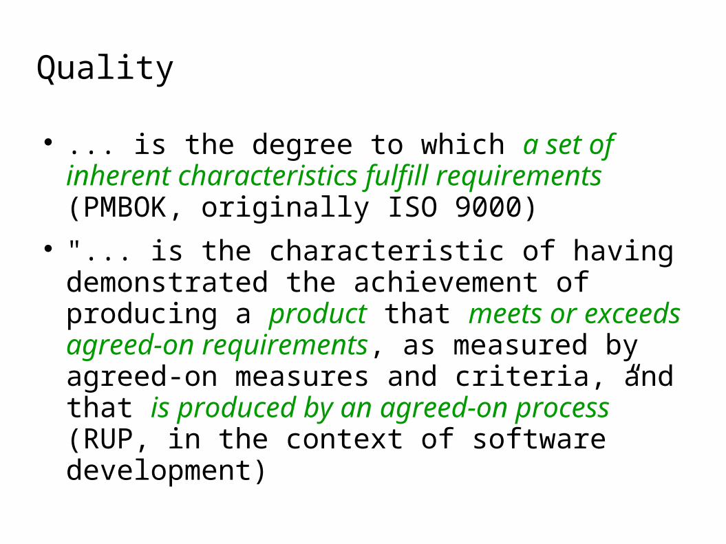
Quality
... is the degree to which a set of inherent characteristics fulfill requirements (PMBOK, originally ISO 9000)
"... is the characteristic of having demonstrated the achievement of producing a product that meets or exceeds agreed-on requirements, as measured by agreed-on measures and criteria, and that is produced by an agreed-on process” (RUP, in the context of software development)

Quality
Producer’s Viewpoint – the quality of the product meets the requirements
Customer’s Viewpoint – the quality of the product is “fit for use” or meets the customer’s needs
Quality also includes: identifying the measures and criteria to demonstrate
the achievement of quality the implementation of a process to ensure that the
product created by the process has achieved the desired degree of quality, and can be repeated and managed

Project quality management
... addresses the management of the project and the product of the project.
... processes in PMBOK: Planning quality – identifying quality
requirements and/or standards, and documenting Performing quality assurance – auditing the
quality requirements and the results from quality control measurements
Performing quality control

Perform quality control
... process of monitoring and recording results of executing the quality activities to assess performance and recommend necessary changes
Quality control is performed throughout the project.
Quality standards include project processes and product goals.
Quality control activities identify causes of poor process or product quality and recommend and/or take action to eliminate them.

Perform Quality Control Tools and Techniques
Cause and effect diagrams Control charts Histogram Pareto chart Run chart Scatter diagram Statistical sampling Inspection Approved change requests review

Ishikawa Fishbone (Cause and effect) diagram

Ishikawa Fishbone Diagram
The Fishbone Diagram is a pictorial means of expression of a list that shows the relationship between some effect and all the possible causes influencing it

Ishikawa Fishbone Diagram
There are a few standard choices for different sectors (fishbone suggested categories):
Service Industries (4S)
· Surroundings · Suppliers
· System · Skills
(+ Safety)
Administration/ Marketing (8P)
· Product (or service) · Price
· People · Place · Promotion
· Procedures · Processes
· Policies
Manufacturing Industries (6M)
· Machines · Methods
· Materials · Measurements
· Mother Nature (Environment)
· Manpower (People)

Ishikawa Fishbone Diagram
In any organization problem analyzing tool is crucial to success. In software quality management the Fishbone diagram is used for this purpose.
Possible causes are usually classified into six categories: method, man, management, measurement, material, machine.

Ishikawa Fishbone Diagram
Method – ways of doing things or the procedures followed to accomplish a task. A typical cause under the method category is not following instructions or the instructions are wrong.
Man – people are responsible for the problem. The problem may have been caused by people who are inexperienced.
Management – project management. Poor management decisions may cause technical problems.

Measurement – measurement refers to metrics that are derived from a project. Problems may occur if measurements are wrong or the measurement technique used is not relevant.
Material – material basically refers to a physical thing. Software can't always handle errors caused by bad material, for instance a bad backup tape, so while material may be the least likely cause, it is a possible cause.
Machine – a machine in software usually refers to the hardware, and there are a lot of possibilities that a problem can be due to the machine.

Ishikawa Fishbone Diagram
After identifying a problem, the leader initiates a discussion with the project team to gather information about the possible causes until arriving at the root cause.
If possible root cause has been identified the action plan has to be derived to fix it.

Domino server crash

Conclusion
Ishikawa Diagram is very useful and widely applicable tool for analyzing and finding the root cause to a complicated problem.
The results are presented in a pictorial form, that everyone can understand and see their contribution to solving the problem.
This method allows also brainstorming in a group to increase the creativity in team and improve team spirit.

THANK YOU!