IS 8110 (2000): Well Screens and Slotted Pipesm= indian standard well screens and slotted pipes —...
23
Disclosure to Promote the Right To Information Whereas the Parliament of India has set out to provide a practical regime of right to information for citizens to secure access to information under the control of public authorities, in order to promote transparency and accountability in the working of every public authority, and whereas the attached publication of the Bureau of Indian Standards is of particular interest to the public, particularly disadvantaged communities and those engaged in the pursuit of education and knowledge, the attached public safety standard is made available to promote the timely dissemination of this information in an accurate manner to the public. इंटरनेट मानक “!ान $ एक न’ भारत का +नम-ण” Satyanarayan Gangaram Pitroda “Invent a New India Using Knowledge” “प0रा1 को छोड न’ 5 तरफ” Jawaharlal Nehru “Step Out From the Old to the New” “जान1 का अ+धकार, जी1 का अ+धकार” Mazdoor Kisan Shakti Sangathan “The Right to Information, The Right to Live” “!ान एक ऐसा खजाना > जो कभी च0राया नहB जा सकता ह ै” Bhartṛhari—Nītiśatakam “Knowledge is such a treasure which cannot be stolen” IS 8110 (2000): Well Screens and Slotted Pipes [MED 21: Diamond Core and Waterwell Drilling]
Transcript of IS 8110 (2000): Well Screens and Slotted Pipesm= indian standard well screens and slotted pipes —...

Disclosure to Promote the Right To Information
Whereas the Parliament of India has set out to provide a practical regime of right to information for citizens to secure access to information under the control of public authorities, in order to promote transparency and accountability in the working of every public authority, and whereas the attached publication of the Bureau of Indian Standards is of particular interest to the public, particularly disadvantaged communities and those engaged in the pursuit of education and knowledge, the attached public safety standard is made available to promote the timely dissemination of this information in an accurate manner to the public.
इंटरनेट मानक
“!ान $ एक न' भारत का +नम-ण”Satyanarayan Gangaram Pitroda
“Invent a New India Using Knowledge”
“प0रा1 को छोड न' 5 तरफ”Jawaharlal Nehru
“Step Out From the Old to the New”
“जान1 का अ+धकार, जी1 का अ+धकार”Mazdoor Kisan Shakti Sangathan
“The Right to Information, The Right to Live”
“!ान एक ऐसा खजाना > जो कभी च0राया नहB जा सकता है”Bhartṛhari—Nītiśatakam
“Knowledge is such a treasure which cannot be stolen”
“Invent a New India Using Knowledge”
है”ह”ह
IS 8110 (2000): Well Screens and Slotted Pipes [MED 21:Diamond Core and Waterwell Drilling]


m=
Indian Standard
WELL SCREENS AND SLOTTEDPIPES — SPECIFICATION
(Second Revision)
ICS 23.040
0 BIS 2000
BUREAU OF INDIAN STANDARDSMANAK BHAVAN, 9 BAHADUR SHAH ZAFAR MARG
NEW DELHI 110002
—
October 2000 Price Group 7
Diamond Core and Waterwell Drilling Sectional Committee, ME21
FOREWORD
This Indian Standard (Second Revision) was adopted by the Bureau of Indian Standards, ker the draft finalizedby the Diamond Core and Waterwell Drilling Sectional Committee had been apprcwed by the MechanicalEngineering Division Council.
This standard was first published in 1976. Subsequently it was revised and first revision was published inNovember 1985. In the first revision, following modifications were included:
a) FRP Pipes have been included for the manufacture of screens and slot pipes.
b) In addition, the materials of manufacture have been clearly specified.
c) Additional design features have been added.
d) Requirement pertaining to FRP pipes have been included.
e) Selection criteria of slot sizes has been included.
The second revision has been undertaken to include requirements for wire wound cage type well screens. Thepresent revision only gives a brief idea about this type of screen. This type of screens are widely used across theworld, due to improved efficiency and life of tubewells thereby saving pumping energy. The production ofthese types of screens has recently commenced in India. Many government and semi-government bodies havestarted using these screms and the use is expected to widely increase due to its advantages.
Moreover, the well screen is the most critical element of tube well affecting its life, pump maintenance andefficiency. The present standard is not adequately providing the guideline and definition with regard to importantparameter of well screen effecting the tube well efficiency, energy consumption and life.
During this revision the well screens and slotted pipes have been made amenable for product certification so thatthe users can be assured of consistent and right quality of well screens.
In the preparation of this standard assistance has been derived from the following standards:
ANSIIAWWA, Al 00-90 Water wells.
AISI -304:1963 Stainless and heat resisting steels.
For the purpose of deciding whether a particular requirement of this standard is complied with, the final value,observed or calculated, expressing the result of a test or analysis, shall be rounded off in accordance with IS.2:1960 ‘Rules for rounding off numerical values (revised)’. The number of significant places retained in therounded off value should be the same as that of the specified value in this standard.

IS 8110:2000
Indian Standard
WELL SCREENS AND SLOTTEDPIPES — SPECIFICATION
(Second Revision)
1 SCOPE
Specifies the types and the technical requirements ofwell screens and slotted pipes used in tube wells.Further it gives detailed specifications, selectioncriterion, testing and inspection methods for wirewound cage type well screens.
2 REFERENCES .
The following standards contain provisions whichthrough reference in this text, constitute provisionsof this standard. At the time of publication, the editionsindicated were valid. All standards are subject torevision, and parties to agreements based on thisstandard are encouraged to investigate the possibilityof applying the most recent editions of the standardsindicated below:
IS No.
280:1978
531 : 1981
1239 (Part 1) :1990
3589: 1991
4270: 1992
4412: 1981
6528: 1995
10151 : 1982
Title
Specification for mild steel wire forgeneral engineering purposes (third
revision )
Leaded brass strips for instru:nentparts (second revision)
Mild steel tubes, tubulars and other
wrought steel fittings: Part I Mild
steel tubes ~ifth revision)
Seamless or electrically welded steelpipes for water, gas and sewage(168.3to2032 mm outside diameter)
(second revision)
Steel tubes used for water wells(second revision)
Copper wires for genera] engineeringpurposes (first revision)
Stainless steel wire (first revision)
Polyvinyl chloride (PVC) and itscopolymers for its.safe use in contactwith foodstuffs, pharmaceuticals anddrinking water
3 TERMINOLOGY
3.1 Well Screens
Well screens are specially fabricated screen pipes fromdifferent materials which can have wider range ofslot
open in: from much finer to coarse compared to slottedpipes.
3.2 Slotted Pipes
Slotted pipes are pipes with slots cut into them in apattern suitable to the basic material of the pipe.
3.3 Terminology — Relating to Cage Type Wire
Wound Screen
3.3.1 Slot Opening
It is the width of opening for entry of water.
3.3.2 Percentage Open Area
It is the open area available for entry of water as
percentage of total outside surface area of pipe.
3.3.3 Profile Wire
Shaped wire which is spirally wound.
3.3.4 Support Rods
The longitudinal shaped/circular rods supporting theprofile wire.
3.3.5 EIId Rings
These are rings or couplers welded at both ends of
screen to facilitate joining with other pipes.
3.3.6 Collupse Strength
It is the strength of screen to withstand surroundinghydrostatic pressure on outside surface.
3.3.7 Tensile Strength
It is the strength of the screen to withstand tensileload.
3.3.8 Push Strength
It is the maximum separating force that weld jointbetween profile wire and support rod can withstand.
3 y ~ pe,~etration. .. .
It is the amount of penetration between profile wireand support rod after fusion welding.
3.4 Terminology — Relating to Performance
Characteristics
3.4.1 Tub_eWell E@ciency
The formation loss (head loss) required to produce flow
1
IS 81-10:2000
divided by the total drawdown observed in the well.
3.4.2 Dt-awdowt/Deprc.s,sion
The difference in elevation between the static andpumping water level.
3.4.3 Specific Cupucit)
Tha ratio of the discharge to the drawdown itproduces, measured under the well (l/rein/m ofdrawdown).
3.4.4 Well Development
Development of aquifers by compressed air or anyother suitable method.
3.4.5 Clogging
Blockage of slots by sediment or sand particles.
3.4.6 Entrance Vklocity
Velocity at which water tlows from outside to insidethe tube well through screen.
3.4.7 Laminar Flow
Movement of tluid particles in essentially parellelpaths.
4 TYPES
4.1 The following are thescreens and slotted pipes:
a) Plain slotted pipes
b) Bridge slotted pipes
various types of well
Type A
Type B
c) Mesh wrapped screens Type C
d) Cage type wire-wound screens Type D
e) Pre-packed resin bounded, gravel Type Escreens
t) Brass screens Type F
4.2 Brief Description
4.2.1
a)
b)
c)
d)
Follo-wing are the various types of well screens:
Plain .slottedpipes — These are pipes with slotscut by milling.
Bridge slotted pipes — The slots here are notcut but pressed out.
Mesh wrapped screens — These are made bywrapping Copper mesh over perforated steel
pipe using spacers about 3 mm thick in betweenthe copper mesh and perforated pipe.
Cage type wire wound screen — These arespecial type of screens where in a continuous
shaped profile wire is spirally wound aroundseries of longitudinal support rods of circularor shaped section with each intersection ofprofile wire and support rod welded by ElectricResistance Fusion Welding Process. The
2
longitudinal support rods are welded to endrings at both ends to facilitate joining withcasing pipes or other screens by butt weldingor threading.
e) Pre-packed resin bonded gravel screens —
Gravel is pasted on the perforated pipe withthe help of resin type adhesive material. Thethickness of gravel bond varies between 10 to15 mm depending upon the diameter of thebase pipe used.
t) Brass screen — Brass screens are made from
brass sheet in which slots of required sizes arecut before rolling.
5 MATERIALS
5.1 The well screens and slotted pipes shall be madeof either corrosion-resistant material or steel pipeshaving sufficient thickness to guard against the affect
Dfcorrosion and to ensure reasonable life of tubewell.The following are the recommended materials forvarious types of well screens and slotted pipes:
a) Low carbon or mild steel;
b) Leaded brass sheet (seeIS531 );
c) Fibre glass reinforced thermosetting plastics;
d) PVC (see IS 10151); and
e) Copper wire (seeIS4412), galvanized steel wire(see IS 280) and stainless steel wire (seeIS 6528).
5.2 Suitable material other than those given abovewhich has better properties may also be used as agreedto between the purchaser and the manufacturer.
6 DESIGNATION
The screens shall be ,designated by the followingparticulars:
a) Type of well screen, A, B, C, D, E and R
b) Nominal bore;
c) GradeiThickness; and
d) Slot opening.
7 SELECTION CRITERION
7.1 Length of Screen
The length of screen shall be governed by thethickness of aquifer and shall be sufficient to obtainthe designed specified yield from tubewell. However,the minimum total lengths shall be such that theentrance velocity is less than the permissible entrancevelocity of 0.03 m/s to ensure longer life of the well.The lengths of individual pipes shall be such as toafford easy handling for transport and lowering intowells, and removal in the case of recovery, etc. The
lengths shall be such that there is minimum wastage
.—
in using of various length imslde the well and to ensurethat the combinations from the nearest requirement toobtain the estimated specit’ic yield of the well. Theymay be in random lengths specified by the user inconsultation with the manufacturer. To account forpossibility of inaccuracy in logging, screen shall notbe placed in at least 0.3 m on both sides of the slratum.
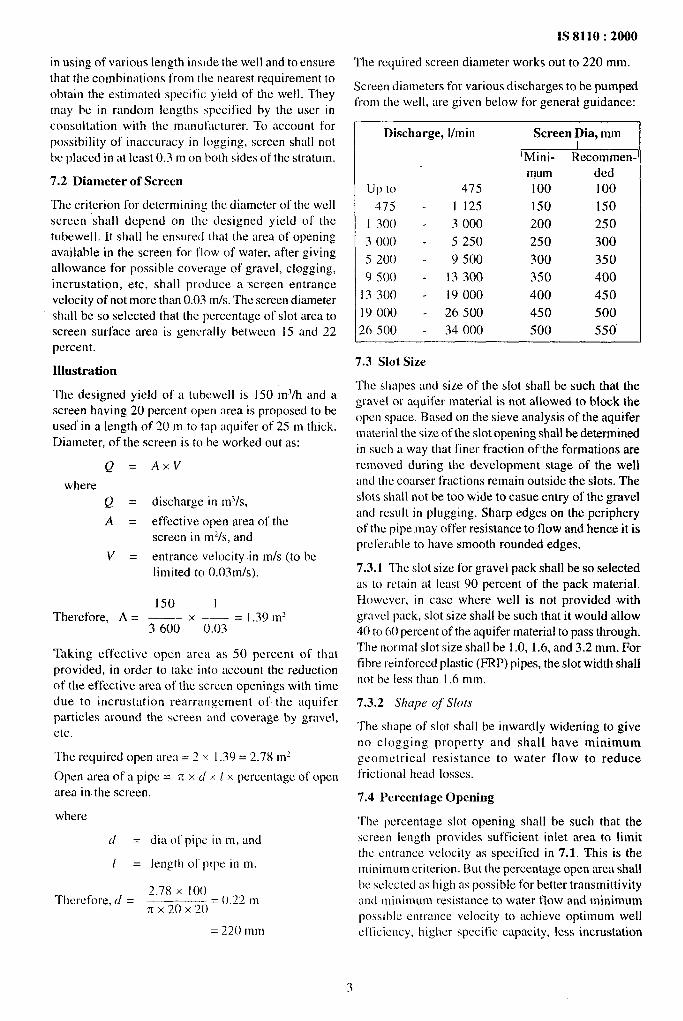
7.2 Diameter of Screen
The criterion for determining the diameter of the wellscreen ‘shall depend on the designed yield 01 thetuhewell. It shall he ensured (hat the area of’openingavailable in the screen for flow of water, after givingallowance for pc)ssible coverage of gravel, clogging,incrustation, etc, shall produce a -screen entrancevelocity of not more than 0.03 m/s. The screen diametershall be so selected that the percentage of slot area toscreen surface area is generally between 15 and 22percent.
Illustration
The designed yield of a tubewel] is 150 mq/h and ascreen having 20 percent open area is proposed to beused” in a length of 20 m to tap aquifer of 25 m thick.
Diameter, of the
Q=
where
Q=
A=
v=
Therefore, A =
screen is to be worked outas:
Ax.V
discharge in m~/s,
effective open area of thescreen in mz/s, and
entrance velocity in m/s (to belimited to 0. f)3m/s).
150 I—x —---= 1.39 m’
IS2JIIU : XJuu
The rc!quil”edscreen diameter works out to 220 mm.
Screen diameters for various discharges to be pumpedfrom the we] 1,are given below for general guidance:
Discharge, l/rein Screen Dia, mm
‘Mini- Recommen-1mum ded
up 10 475 100 100
475 - I 125 150 150
1 300 - 3000 200 250
3000” - 5250 250 300
5200 - 9500 300 350g 500” - 13300 350 400
I 3300 - 19000 400 450] 9 ()()() - 26500 450 500
26500 - 34000 500 550’
7.3 Slot Size
The shapes and size of the slot shall be such that theW:iVeI or aquifer material is not allowed to block theDopen space. Based on the sieve analysis of the aquifermaterial the size of the slot opening shall be determinedin such a way that finer fraction of the formations areremoved during the development stage of the welland the coarser fractions remain outside the slots. The
slots shall not be too wide to casue entry of the graveland result in plugging. Sharp edges on the peripheryof the pipe may offer resistance to tlow and hence it isprclerahle to have smooth rounded edges.
7.3.1 The slot size for gravel pack shall be so selectedas to retain at least 90 percent of the pack material.However, in case where well is not provided withq-:Lvel p~lck, S]ot size shall be such that it would allowo
3600 0.03
Taking effective open area as 50 percent of thatprovided, in order to take into account the reductionof the effective area oi’ the screen openings with time
due to incrustation rearrangement of the aquiferparticles around the screen and coverage by gravel,etc.
The requireci open area= 2 x 1.39 = 2.78 m2
Open area of a pipe = n x d x / x percentage of openarea in. tile screen.
where
d=
1=
Thtxcfore, d =
dia 01 pipe in m, and
length 01 pipe in m.
2.78 X 100——–.––.–.. . (),22 mn x 20 x 20
= ~~() mm
—
40 to 60 percent of the aquifer material to pass through.
The normal slot size shall be i .0, 1.6, and 3.2 mm. Forfibre reinforced piastic (FRP) pipes, tile slot width shallnot be less than 1.6 mm.
7.3.2 .$hope of Slots
The shape of slot silall be inwardly widening to giveno ciogging property and shail have minimumgeolnclrica] resistance to water f{ow to reduce
frictional ileaci losses.
7.4 Percentage Opening
The percentage slot opening shali be such that thescreen length provides sufficient iniet area to limit
tile unwance veiocity as specified in 7.1. This is theminimum criterion. But the percentage open area shailIx sclc.cled as iligh as possible for better transmiltivityfind minimum resistance to water (1OWand minimumpmsib]c entrance velocity to achieve optimum wellct’ficicncy, higher specilic capacity, iess incrustation
3

—
1S8110 :2000
and minimum drawdown to result into saving ofpumping energy.
7.5 Distribution of Slots
The slots shall be cut in a pattern designed to get evendistribution of flow all over the periphery of the pipe.The slots shall be distributed in rows as closely andevenly as possible, staggering the slots between eachrow.
The screens with evenly spaced continuous horizontalslot (perpendicular to screen axis) throughout theperiphery without leaving blind spots shall bepreferred for improved well performance.
7.6 Collapse Strength
Depending upon the depth of tube well, the static waterlevel column and geological conditions, the screenswith adequate collapsible strength shall be used.
7.7 Tensile Strength
The screens must have sufficient tensile strength towithstand the weight of pipe assembly under it.
8 SPECIFIC DESIGN FEATURE
8.1 Plain Slotted Pipes
8.4.1 Low Carbon or Mild Steel Slotted Pipes
The slots shall be cut by milling or by slitting saw.The recommended thicknesses of different diametersfor various depths of tube well under normal conditionsis given in Table 1.
8.1.1.1 Typical slot pattern of well screen is shown inFig. 1 and Fig. 2.
8.1.1.2 The slots shall not be cut within 12 mm oneither side of the longitudinal welded joints of thepipes.
8.1.1.3 The plain space after thread cutting over the
larger diameter pipes shall not be less than 150 mm sothat wrenches could easily be used on plain spaceonly.
8.1.2 FRP Pipes
The FRP slotted pipes shall be manufactured by thefilament winding process. The slots shall be cut bymilling. The slotting pattern (see Fig. 3) shall be such
as to ensure the minimum cutting of the glass fibre inthe pipe and thereby maintaining maximum strength.
8.1.2.1 The recommended thickness of FRP pipes isgiven below:
Depilt Thickness of Pipe ,jbr Given Diu in mm
of well
m 150 200 250 30.0 350
150 5,00 6.00 6.50 8.25 8.50
300 6.00 6.7’5 8.00 9.00 9.50
8.1.2.2 The pipes made from FRP based materialshall fulfill the requirements as given in Annex A.
8.2 Mesh Wrapped Screens
The pipes used in mesh wrapped screens shall be ofmild steel or low carbon steel. The diameter ofperforations shall not be less than 12 mm and thedistance between the two adjacent holes shall be
between 25 and 40 mm depending upon the diameterand the thickness of the pipes used. The pipe thicknessshall be same as given in Table 1.
The spacers shall be of mild steel and shall be ofthickness 3 mm minimum and shall be 6 mm wide.The distance between the two adjacent spaces shallbe 75 mm minimum.
The copper mesh shall be -made of copper wireaccording to IS 4412 and shall not be less than0.710 mm in thickness.
Table 1 Thickness of Pipes
(Clause 8.1.1. and 8.2)
Depth Thickness for Pipe Sizeof well (OD) in mm
m 166.6/ 168.3 219.1 273.00 323.80 355.60
50 4.85 7.04 7.09 8.38 9.52
100 5.4 7.04 7.90 8.38 9.52
125 5.4 7.04 7.80 8.38 9.52
150 5.4 7.04 7.80 8.38 9.52
175 5.4 7.04 7.80 8.38 9.52
200 5.4 7.04 7.80 8.38 9.52
250 7.11 8.18 9,27 9.58 9 ,“52
275 7.11 8.18 9.27 9,52 9.52
300 7.11 8.18 9.27 9,52 9.52
——
4

IS 8110:2000
IIII I r3.2
bI
-100+754III1III
~---- A-
----- ----- ------ ----- ---
t
------ ----.- ----- ----- -.
All dimensions in millimetres.
FIG.1 DEWLOPEDVIEWOFATmCAL WELLSCREEN,Ftm !kcmm T=
J- -J-= --4-1
. 6.5
—
All dimensions in millimetres.
FIG.2 S~G ARRANGEMENT
5
IS 8110:2000
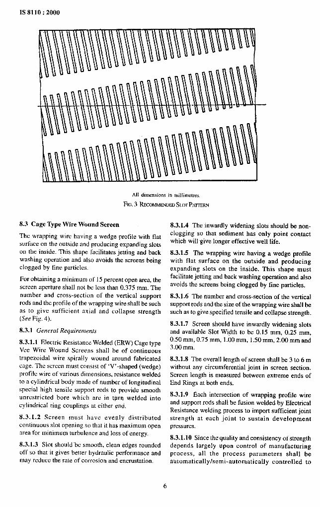
All dimensions in millimetres,
FIG.3 RECOMMENDEDSI.XXPATTERN
8.3 Cage Type Wire Wound Screen
The wrapping wire having a wedge profile with flatsurface on the outside and producing expanding slotson the inside. This shape facilitates jetting and backwashing operation and also avoids the screens beingclogged by fine particles.
For obtaining a minimum of 15 percent open area, the
screen aperture shall not be less than 0.375 mm. Thenumber and cross-section of the vertical supportrods and the profile of the wrapping wire shall be suchas to give sufficient axial and collapse strength
(See Fig. 4).
8.3.1 General Requirements
8.3.1.1 Electric Resistance Welded (ERW) Cage typeVee Wire Wound Screens shall be of continuoustrapezoidal wire spirally wound around fabricatedcage. The screen must consist of ‘V’-shaped (wedge)profile wire of various dimensions, resistance weldedto a cylindrical body made of number of longitudinalspecial high tensile support rods to provide smooth
unrestricted bore which are in tfsrn welded intocylindrical ring couplings at either ~nd,
8.3.1.2 Screen must have evelhly distributedcontinuous slot opening so that it ha$ maximum openarea for minimum turbulence and loss of energy.
8.3.1.3 Slot should “be smooth, clean edges roundedoff so that it gives better hydraulic performance andmay reduce the rate of corrosion and encrustation.
8.3.1.4 The inwardly widening slots should be non-clogging so that sediment has only point contactwhich will give longer effective well life.
8.3.1.5 The wrapping wire having a wedge profilewith flat surface on the outside and producingexpanding slots on the inside. This shape mustfacilitate jetting and back washing operation and alsoavoids the screens being clogged by fine particles.
8.3.1.6 The number and cross-section of the verticalsupport rods and the size of the wrapping wire shall besuch as to give specified tensile and collapse strength.
8.3.1.7 Screen should have inwardly widening slotsand available Slot Width to be 0.15 mm, 0.25 mm,0.50 mm, 0.75 mm, 1.00 mm, 1:50 mm, 2.00 mm and3.00 mm.
8.3.1.8 The overall length of screen shall.be 3 to 6 mwithout any circumferential joint in screen section.
Screen length is measured between extreme ends ofEnd Rings at both ends.
8.3.1.9 Each intersection of wrapping profile wireand support rods shall be fusion welded by ElectricalResistance welding process to import sufficient jointstrength at each joint to sustain developmentpressures.
8.3.1.10 Since the quality and consistency or strengthdepends largely upon control of manufacturing
process, all the process parameters shall beautomatically /semi-automatically controlled to
6

IS 8110:2000
R“:)
PECIAL HIGH TENSILE
T
SUPPORT RODS TOPROVIDE SMOOTH,
NRESTRICTED BORE
URE
/ SPECIAL WEDGE SECTIONWRAPPING WIRE HELICALLYWRAPPED TO FORM Conti-nuous NON-CLOGGING
APERTURE
UNOBSTRUCTED=FLOW OURING @DEVELOPMENT
a
I I APERTURE(SLOT)
AS REQUIRED
‘%P’bw!K!?A
SECTION THROUGH SCREEN
All dimensions in millimetres.
FIG.4 CAGETYPEWnw WOUNDSCREENS
7

1S8110 :2000
ensure quality and consistency of strength. 8.3.2.2 The screens are classified as regular and heavy
8.3.2 Material of Constructiondepending on their thickness.
8.3.2.1 The screens shall be made from wires of either 8.3.3 Dimensional Parameters
of the following materials:The dimensions of screen shall be as given below for
a) Low Carbon Galvanized (LCG) Steel two classes and two materials.(see IS 280)
b) Stainless Steel (SS) (see designation X04 Cr 18 8.3.3.1 LCG screens suitable for well depth up to
‘Ni10 of IS 6528) 200 m:
Nom. 1.D. 0.D, Thickness Open Area ,fm Different Slut Openings, mmSize
m m mm mm m m 0,15 0.20 0.25 0.50 0.75 1.00 1.50 2.00 3.0(
PercentageOpen Area
40 40 48.7 4.4
50 52 61 4.4
75 76 88 6.0
100 101 113 6.0
150 153 165 6.0
200 205 219 7.0
250 256 272 8.0
300 306 322 8.0
350 338 362 12.0
9 12 14 25 33 40 - – –
9 12 14 25 33 40 - –
6 8 10 18 25 30 40 47 -
6 8 10 18 25 30 40 47
6 8 10 18 25 30 40 47 –
6 8 10 18 25 30 40 47 -
5 6 8 14 20 25 33 40 50
5 6 8 14 20 25 33 40 50
4 6 7 13 19 23 32 38 48
8.3.3.2 LCG screens suitable for well depth up to 400 m:
Nmn. 1,D. O. D. Thickness Open Areu ,fbr Different SM Openings, mm
Sizemm mm m m mm 0.15 0.20 0.25 0.50 0.75 1.00 1.50 2.00 3.00
Percentage Open Arm
150 153 167 7.0 6 8 10 18 25 30 40 47 -
200 205 221 8.0 5 6 8 14 20 25 33 40 50
250 256 276 10.0 1467’3 ’9233238481300 306 326 I 0.0 14671319233238481
350 338 363 12.5 1356’’’926324212I
8.3.3.3 SS screens suitable for well depth up to 200 m:
Nom. I.D. O.D. Thickness
Siremm
m m mm mm
40
50
75
i 00
150
200
250
300
350
40 48.4 4.2
52 60 4.0
76 86.5 5.2
101 Ill 5.0
153 163 5.0
205 217.5 6.3
256 271 7.3
306 322 8.0
338 358 10.0
Open Areu f[w Different Slot Openings, mm
0.15 0.20 0.25 0.50 0.75 I .00 1.50 2.00 3.OC
Percentage Open AIVa
9 12 14 25 33 40 50 - -
9 12 14 25 33 40 50 - -
6 8 10 18 25 31 40 47 -
6 8 10 18 25 31 40 47 -
6 8 10 18 25 31 40 47 -
6 8 10 18 25 30 40 47 -
5 6 8 14 20 25 33 40 50
5 6 8 14 20 25 33 40 50
5 7 8 IS 21 26 35 41 51
8

IS 8110:2000
8.3.3.4 SSscreens suitable forwell depth upto400m:
Mm. I.D. O.D. Thickness
Sizem m mm m m mm
150 153 165.5 6.3
200 205 221 8.0
250 256 272.5 8.2
300 306 330 12.0
350 338 363.5 12.75
Open Areu,fi)r Di~erent Sk)t Openings, mm I
0.15 O.ZO 0.25 0.50 0.75 1.00 1.50 2.00 3.00Percentage Open Area
6 8 10 18 25 30 40 47 -
5 6 8 14 20 25 33 40 50
5 7 8 15 21 26 35 41 51
4 5 6 11 16 20 27 33 42
4 5 6 11 16 20 27 33 42
. ..—8.3.4 Strength Parameters
The minimum acceptable values of strength parameters shall be as follows for two classes and two materials.
8.3.4.1 LCG screens, for tube well depth up to 200 m:
Nom.
Size
m
40
50
75
100
150
200
250
300
350
C(dlupse Pressure, MPa
Slot Opening
0.15 0.20 0.25 0.50 0.75 I .00 1.50 2.00 3.00
27.5 26.5 25.5 22.1 20.4 18.1 15.2
14.2 14.0 13.7 11.8 10.6 9.6 7.8
14.7 14.4 14.2 12.7 11.8 10.8 9.5 8.3 -
7.1 6.9 6.8 6.2 5.7 5.2 4.5 4.0 -
2.5 2.4 2.4 2.2 2.0 1.9 1.6 1.4 -
1.1 1.0 I .0 0,9 0.9 0.8 0.7 0.6 -
1.2 1.2 1.1 1.1 1.0 1.0 0.9 0.8 0.6
0.7 0.7 0.7 0.6 0.6 0.5 0.5 0.4 0.4
1.7 1.6 1.6 1.5 1.4 1.3 1.2 1.1 0.9
8.3.4.2 LCG screens, for tube well depth up to 450 m:
Nom. I COllupse Pressure, MPu
Size
Slot Openingmm 0.15 0.20 0.25 0.50 0.75 1.00 1.50 2.00 3.00
150 2.5 2.4 2.4 2.2 2.0 1.9 1.6 1.4 -
200 2.3 2.3 2.2 2.1 1.9 1.8 1.6 1.4 1.2
250 3.8 3.8 3.7 3.4 3.2 3.0 2.7 2.5 2.1
300 -2.3 2.3 2.3 2.1 2.0 1.9 I .7 1.5 1.3
350 1.8 1.8 1.8 1.7 1.6 1.5 1.4 1.3 1.1
Tensile
bad
kN
29.43
29.43
39.24
49.05
58.86
137.34
176.58
206.01
461.07
Tensile
Loud
kN
98.10
137.34
176.58
206.01
461.07
9

lS8110 :2000
8.3.4.3 SSscreens, fortube well depth upto200m:
Nom. Colkip.re Prc.ssui-e, MP(i TensileSize Loud
Slot Opening
m m 0.15 (),~ ().25 0.50 0.75 1.00 1.50 2.00 3.00 kN
40 30.2 29,4 28.4 25.0 ‘2~,] 20.1 16.7 39.24
50 15.7 [5.2 14.7 12.7 11.3 10.3 8.3 — 39.24
75 5.6 5.4 5.2 4.7 4.4 4.0 3.4 3.0 – 49.05
I 00 2.6 2.6 2.5 2,3 2.1 2.0 1.7 1.5 – 78.4s
150 0.9 0.9 0.9 0.8 0.7 ().7 ().6 0.5 - 107.91
200 1.1 1.1 1.1 1.0 0.9 0.8 0.7 0.6 – 186.39
250 1.3 1.3 1.2 1.2 1.1 1.0 0.9 0.8 0.7 235.44
300 0.8 0.8 0,7 0.7 0.6 0.6 0.5 0.5 0.4 392.40
350 1.2 1,’2 1.1 1.0 1.0 0.9 0.8 0.7 0.6 716.13m
8.3.4.4 SSscreens, fortube welldepthupto450m:
Nom. COlktp.ve Pressure, MPU TensileSi7.e Load
S10[ Opening
m m 0.1s 0.20 0.25 0.50 0.75 [.00 1.50 2.00 3.00 kN
150 2.3 2.3 2.2 2.0 1.9 1.7 1.5 1.3 - 137.34
200 2.4 2.3 2.3 2.1 2.0 I .9 1.6 1.5 1.2 264.87
2s0 1.7 1.7 1.6 1.5 1,4 1,3 1.1 1.0 0.8
300 3.4 3.3 3.3
343.35
3.1 2.9 2.7 2.5 2.4 2.0 578.79
350 2.5 2.5 2.5 2.4 2.2 2.1 1.9 1.8 1.5 716.13
8.3.5 Tolerances
The maximum permissible values of tolerances on dimensions shall be as given below:
Screen ID * 1.5 percentScreen OD * 1.5 percentScreen Thickness ~ 1.0 percentEnd Ring ID * 1.5 percentEnd Ring OD * 1.5 percentEnd Ring Thickness ~1 2.5 percentScreen overall length *50mm
Slot Opening:
Slot Size Tolerance Max Deviation(70 percent of the readings) (30 percent of the readings)
0.15 mm0.20 mm0.25 mm0.50 mm0.75 mm1.00 mm1.50mm2.00 mm3.00 mm
*0.05 mm*0.05 mm*0.07 mm~0.10mm~0.10mm*0.15 mm~0.15 mm*0.30 mm+0.30 mm
*O.1O*O.1Oto.15.* 0.2* 0.2* 0.3~ 0.3f 0.6y 0.6
10

1S 8110:2000
8.3.6 Inspection and Testing Procedures
8.3.6.1 Sampling platr
Tests SamplingI
a) Type Tests i Nominal size
i) collapse Up to 100 mmPressure test
Above 100 mmand up to 300 mmAbove 300 mm
ii) Tensile Minimum numberStrength test
#of samples per lot
Sample size ‘
One for every 400pipes or part thereofC)ne for every 200pipes or part thereofOne for every I00pipes or part thereof
Two
I b) Routine Tests
i) Visual Each pieceii) Dimensional one in ten piecesiii) Slot opening One in ten piecesiv) Weld joint strength One in twenty five pieces
8.3.6.2 Method of testing
a)
b)
L!)
i)
ii)
iii)
iv)
v)
/vi)
cl)
Dimettsional check — With thehelp of measuringinstruments to verify dimensions to be withintolerance limits.
Slot opening — With f{’eler gauges: Slot size tobe measured for all slots over 100 mm lengthin each metre length of screen randomly.70 percent of the slots shall fall within thetolerance and no slot shall exceed maximumdeviation.
Visual checks
There should not be ilny sudden change inI.D. or O.D. of screen.
No profile wire or support rod shall be bent ortwisted.
No profile wire and support rod intersectionshall ,be found without welding.
Welding of support rods to end rings shall beuniform with each support rod.
Screens shall be reasonably concentric andstraight with end faces reasonably square toaxis.
At the joining point ot screen and end ring,there sha] I be no gap larger than slot opening.
Collapse pressure — Screen sample 0{ apprl)-priatc length should bc closed at one end bywelding plain M.S. Plate. The screen outsidesurface to bc wrapped with strong plastic film to
block ail slots and shall t-wleak proof. The sampleto be bolted inside bigger pressure pipe to leavean annular space of more than” 25 mm radially.
—
e)
1)
Hydraulic oil to be pumped in this annular spaceand pressure to be built up to the specified limitof collapse strength for that size. Screen sampleshall not collapse at this pressure.
Tensile strength — Screen sample of appropriatelength with end rings should be closed at onec nd by welding strong mild steel plate and flangewelded at another end forbolting. The sample isto he bolted on hydraulic cylinder such that itspiston pushes against the closed end. Hydraulicpiston pressure is to be applied to bring screenunder tension up to the specified value of tensileload as given in 8.3.4. The screen shall not breakor support rod should not loosen from end ring.Any other suitable method may also be used.
Weld ,joinf strength — A small strip over oneSL]pport rod to be cut from the end of the screenin push test apparatus, with the help of twometallic fingers the profile wire shall be pushedby hydraulic cylinder to separate it from supportrod. It shall not separate at specified value ofload as agreed to between the purchaser and themanuthct urer.
8.3.6.3 Criteria for conformity
a) Dimensional check — All dimensions shallcon form to the drawin or contract and tolerancesshuil be as given in 8.3.5.
“b) Slot opening — The actual values shall bewithin the tolerance limit applicable ‘as givenin 8.3.5.
c) Visu{d check — No abnormalities shall be found.
II

IS 8110:2000
d) Collapse pressure —The collapse sh,all nottake place at collapse pressure lesser than thatspecified for the respective size as given in8.3.4.
e) Tensile strength —Thefaihtre shall not takeplace at tensile load lesser than that specifiedfor the respective size as given in 8.3.4.
t) Weld joint strength—The separation ofwrapping wire and support rod shall not occurat push load lesser than that specified ‘for therespective size as given in 8.3.4.
8.3.6.4 Retests of samples
In case any one of the test pieces first selectedfail to pass any of the tests specified, two furthersamples shall be selected for testing in respectof each failure from the same lot. Should the testpieces from both these additional samples pass,the material represented by thetest samples shallbe deemed to comply with the requirement ofthat particular test. Should the test pieces fromeither of the additional samples fail, the materialrepresented by the test samples shall be rejected.
NOTE — Weld strength ~quirements shall be included
later as sufficient data is not available. TM such time the
requirements are not included in the specification, theweld strength may be as agreed to between the manufac-
turer and the purchaser.
8.4 Brass Screerts
8.4.1 The screens shall be manufactured from brasssheets conforming toIS531 unless otherwise specified.The minimum thickness of the sheet shall be as givenbelow:
Depth of Tubewell, Thickness, mm Min ofDiameter of Screens
1150mm 200mm 250mm 300mm~
up to 100 3.2 4.5 5.4 5.4
Above 100 4.5 5.4 5.4 5.4
8.4.2 Distance between slots and rows shall be asgiven in Fig. 5A and 5B.
9 GENERAL REQUIREMENTS
9.1 The screens shall possess adequate resistance .tocorrosion and incrustation due to chemical content of
soil and water. Where water is of highly -incrustingnature, the screen shall be such as to permit the waterto enter the well with minimum resistance. Also,wherever incrustation commonly occurs it should bedesirable to choose the material for the screen that canwithstand subsequent acid treatment for removingincrustation.
9.2 The screen shall be as far as possible of singlemetal construction to avoid galvanic corrosion.
9.3 Well screens shall be threaded and socketed, plainbevel ended, collared or male and female types so thatconvenient lengths could be added. The slotted pipescreens shall have adequate strength to withstandaxial, collapse and hydrostatic ioads.to be experiencedduring development and use.
10 GUIDELINES FOR SELECTION OF SLOTSIZE
The guidelines for selection of slot size is given inAnn9x B.
11 MARKING
11.1 Each pipe shall be marked with the followingdetails:
a) Nominal size in mm,
b) Overall length in m,
c) Manufacturer’s trade-mark,
d) Grade or thickness in mm,
e) Slot size in mm,
t) Material.
11.2 BIS Certification Marking
11.2.1 The pipes may also be marked with the StandardMark.
11.2.2 The use of the Standard Mark is governed bythe provisions of the Bureau.of Indian Standards Act,1986 and the Rules and Regulations made thereunder.The details of condition under which a license for theuse of the Standard Mark may be granted tomanufacturers or producers maybe obtained from theBureau of Indian Standards.
12 PACKING
The pipes shall be packed as agreed to between thepurchaser and the manufacturer.
12

IS 8110:2000
t-X ACr- --n--w
L------- ‘~ V GROOVE SECTIONXX
NB of OD of Sizes 01 Slots No. of Total Area of Water Way B Distance DistancePipe Pipe Rows slots Slots per Area Between Between
w L In Dia per Metre in ‘Percent slots RowsMetre mm2 c D
152 162 0.793 40 16 2 128 67500.160 13.25 2.778 2.627 19.050
152 162 1.587 40 16 1 216 77 191.680 15.18 4.762 6.350 19.050
204 213 0.793 40 16 2800 88816.000 13.28 2.778 3.627 19.050
204 213 1.587 40 16 1 600 101 568.00 15.17 4,762 6.350 19.050
Metil — Bmss sheets according to IS 53”1
All dimensions in .nrillimetres.
5A Brass Screens with Vertical Slots
NOM BOREOF PIPE
c
IF
--------mmmmrrrnnr -------- ----------l trmllrlll---’
11111111111111111111(j
+s
.111111111111L llllllllllll~p 11111111111100
& -+tlMtttl–”– -
111111111111111111-111111111111111111
-pMiitt-f-X 111111111111x
---. --- JUIUUUUUuu ----------- - ------ . .. UUIULIUL---’
l-----+-. ~ V GROOVE SECTION XX
NB of OD of Sizes Of S101s No. of Total Area of Water Way B Distance DistrmcePipe Pipe Rows slots Slots per Area Between Between
w L In Diir per Metre in Percent slots Rows
Metre m mz c D
152 162 0.793 30 12 3300 78507.000 15.41 2.778 3.627 9.525
152 162 1.587 30 12 1884 89697.240 17.79 4.762 6.350 19.525
204 213 0.793 30 12 4400 104676.000 15.63 2.770 3.627 11.303
204 213 1.507 30 12 251.2 119596.320 17.86 4,762 4.762 11.303
Metal — Brass sheets according to IS 531
All dimensions in millimetres.
5B Brass Screens with Vertical Slots
FIG.5 BRASSSCREENS
13

!S 8110:2000
ANNEX A
(Clause 8.1.2.2)
MECHANICAL PROPERTIES OF FIBRE GLASS REINFORCED PLASTIC (FRP) PIPES
A-1 The FRP pipes shall withstand the following tests
A-1.l Mechanical Strength
A-1.l.l Axial Tensile Strength
The ultimate tensile strength of the pipe shall not be
less than 102 kN or ten times the weight of ahypothetical well string comprising 18 m of upperwell casing, 4 m of screen, and 6 m of lower well casing,whichever is greater.
A-1.1.2 Axial Compression Strength
The compressive strength of the pipe when tested inthe axial direction shall not be less than 102 kN.
A-LL3 internal Hydrostatic Pressure Test
The pipe shall withstand a hydraulic pressure of210 N/cm2 continuously. a
A-1.1.4 External Collapse Pressure Test
The slotted pipes shall withstand the followingexternal pressures:
Well Depth Collapse Pressure,
m N/cmz
Over Up to and Including
o- 100 28100 - 150 49150 - 225 70225 - 300 84300 - 400 98
A-1.1.5 Water Absorption and Retention of Strength
Water absorption in boiling water for 72 hours shallbe less than one percent.
Strength retention after boil test shall be at least50 percent of original strength.
NOTES
1 Axial tension and axial compression values given we
based on required handling strength, chiefly from
previous experience. Further the axial tensile value
includes with a safety factor, the load required to withdraw
the well string after gravel packing but before full
development.
2 Internal hydrostatic pressure strength is based on the
ability of slotted pipes to withstand cleaning by explo-
sive of masked string of cordtex.
3 External collapse pressure is based on estimated maximum
pressure likely to be experienced in development,
ANNEX B
( Clause 10)
SELECTION OF SLOT SIZE
B-1 DETERMINATION OF SLOT SIZE
B-1.l The size of slot openings suitable for differentformations shall be based on sieve analysis of theaquifer- material. Following procedure and designcriterion is laid down for general guidance.
B-1.2 A weighed quantity of the thoroughly mixedsample is passed through a set of Indian Standardsieves from No. 75 onwards. The sieves are arrangedsuch that the coarsest sieve is placed at the top and the
finest at the bottom. Atlcr proper shaking, the sieve
set is opened and material retained on each sieve iscorrectly weighed. The cumulative weight passingthrough each sieve is plotted on semilogarithmicgraph paper having percentage weight as ordinate onarithmetic scale and size of the sieve opening asabscissa on logarithmic scale. A smooth graph is thendrawn through the points.
B-1.3 The normal slot size for well without gravelpack (that is, naturally developed) shall be 0.15, to0.5 mm, and for gravel packed well shall be 0.5 mm,
0.75 mm, 1.0 mm, 1.5 mm, 2.0 mm and 3.0 mm.
.—
14

.
10.0
awz~ 6.0
0-%
;
wa &*o
o
IS 8110:2000
VERYFINE SAND
MJCCUUFINE SAND
::A$SE ;$:;~E
SANDGRAVEL
DIAMETER IN MILLIMETRES
FIG.6 TYPICALGRAINSIZEDISTRIBUTIONCURVES(USERCLASSIFICATION)
B-2 AQUIFER MATERIAL CLASSIFICATION
B-2.1 The aquifer material may be classified intovarious categories according to the following ranges
of the particle size:
Fine gravel above 2.0 mm
Coarse sand 0.5 to 2.0 mm
Medium sand 0.25 to 0.5 mm
Fine sand 0.05 to 0.25 mm
Silt 0.002 to 0.06 mm
Clay below 0.000 mm
B-2.2 Grain size curves of a few typical aquifermaterials covering fine to coarse sand are shown inFig. 6.
B-2.3 Effective Diameter
The effective diameter is an index of the measure ofthe fineness of an aquifer. For permeability, all,) isgenerally taken as the effective size.
B-2.4 Uniformity Co-efficient (Cu )
Uniformity co-efficient gives the slope of the majorportion of the grain size distribution curve and isdefined as below:
d,,, (40 percent retained)c“ -
d,,, (90 percent retained)
B-3 GRAVEL PACK
B-3.1 Criteria for design of artificial gravel pack isgenerally expressed in terms of gravel pack ratiowhich is defined as the ratio between the average sizeof the gravel pack material and the average size of theaquifer material. However following design criterionfor gravel pack is recommended based on minimumhead loss through gravel pack and minimum sandmovement:
Pack Aqu$er Ratio
Uniform aquifer with uniform 9 :12.5gravel pack
Non-uniform aquifer with uniform 11 :15.5gravel pack
B-3.1.1 The above criterion is based cm minimumhead loss through gravel pack and minimum sandmovement.
B-3.2 In case gravel pack has to be provided to a wellwhere more than one formation are to be tapped, the
15
1S 8110:2000
gravel pack designed for the finest formations shoukl gradation packs should not contain particles greaterbe provided for all the formations, provided average than 13 mm.grail] size of the material in the coarsest aquifkr is less
than 4 times the 50 percent size of the materials in theB-3.4 The size of the slot opening is governed by the
finest aquifer.size of gravel or aquifer material which it has to retain.The slot size for gravel packed well should be such
B-3.3 To avoid trouble in placing and irrespective of that it retains about 90 percent of the gravel.
-—
16

Bureau of Indian Standards
BIS is a statutory institution established under the Bureau of Indian Standards Act, 1986 to promoteharmonious development of the activities of standardization, marking and quality certification of goodsand attending to connected matters in the country.
Copyright
BIS has the copyright of all its publications. No part of these publications may be reproduced in any formwithout the prior permission in writing of BIS. This does not preclude the free use, in the course ofimplementing the standard, of necessary details, such as symbols and sizes, type or grade designations.Enquiries relating to copyright be addressed to the Director (Publications), BIS.
Review of Indian Standards
Amendments are issued to standards as the need arises on the basis of comments. Standards are also reviewedperiodically; a standard along with amendments is reaffirmed when such review indicates that no changes are
needed; if the review indicates that changes are needed, it is taken up for revision. Users of Indian Standardsshould ascertain that they are in possession of the latest amendments or edition by referring to the latest issue of‘-BIS Catalogue’ and ‘Standards: Monthly Additions’.
This Indian Standard has been developed from DOC : No. MED21 (0450).
Amendments Issued Since Publication
Amend No. Date of Issue Text Affected
BUREAU OF INDIAN STANDARDS
Headquarters :
Manak Bhavan, 9 Bahadur Shah Zafar Marg, New Delhi 110002 Telegrams : Manaksanstha
Telephones :3230131,3233375,3239402 (Common to all offices)
Regional Offices : Telephone
Central : Manak Bhavan, 9 Bahadur Shah Zafar Marg
{
3237617NEW DELHI 110002 3233841
Eastern : 1/14 C. I. T. Scheme VII M, V. I. P. Road, Kankurgachi
{
3378499,3378561CALCUTTA 700054 3378626,3379120
Northern : SCO 335-336, Sector 34-A, CHANDIGARH 160022
{
603843602025
Southern : C. I. T. Campus, IV Cross Road, CHENNAI 600113
{
2350216,23504422351519,2352315
Western : Manakalaya, E9 MIDC, Marol, Andheri (East)
{
8329295,8327858
MUMBAI 400093 8327891,8327892
Branches : AHMADABAD. BANGALORE. BHOPAL. BHUBANESHWAR. COIMBATORFFARIDABAD. GHAZIABAD. GUWAHATI. HYDERABAD. JAIPUR. KANPUR.LUCKNOW. NAGPUR. PATNA. PUNE. RAJKOT. THIRUVANANTHAPURAM.
t
-—
Printed at : Prabhat Offset Press, New Delhi-2

AMENDMENT NO. 1 MAY 2002TO
IS 8110:2000 WELL SCREENS AND SLOTTED PIPES— SPECIFICATION
( Second Revision)
( Page 10, clause 8.3.5) — Substitute ‘t 10 percent’ for ‘t 1.0 percent’ forScreen thickness tolerance.
( Page 13, Fig. 5B, Caption ) — Substitute ‘Brass Screens withHorizontal Slots’ for ‘Brass Screens with Vertical Slots’.
( Page 15, Fig. 6, Caption) — Substitute the following for the existing:
‘TYPICALGRAINSIZEDISTRIBUTIONCURVES( USBR CLASSIFICATION)’
(ME21)Reprography (Jnit, [11S, New Delhi, In=