ANALYSIS OF SCATTERING WITH MULTI-SLOTTED CYLINDER … · ANALYSIS OF SCATTERING WITH MULTI-SLOTTED...
16
Progress In Electromagnetics Research, Vol. 128, 105–120, 2012 ANALYSIS OF SCATTERING WITH MULTI-SLOTTED CYLINDER WITH THICKNESS: TM CASE W.-S. Lee * , H.-L. Lee, H.-S. Jang, H.-S. Tae, and J.-W. Yu Department of Electrical Engineering, KAIST, 291 Daehak-ro, Yuseong-gu, Daejeon 305-701, Korea Abstract—An exact series solution for radiation and scattering of the dielectric-loaded multi-slotted cylinder with thickness is formulated by using radial mode matching technique. The radiated and guided fields are represented in terms of an infinite series of radial modes. By applying the appropriate boundary conditions, the coefficients of radiated and guided fields are obtained. The behaviors of resonance features are characterized for variation in frequencies, source positions, slot thickness, and dielectric coating properties. 1. INTRODUCTION A shield is the layer of conducting material which partially or completely envelops an electric circuit. It therefore affects the amount of electromagnetic radiation penetrating into the electric circuit from the external environment as well as the electromagnetic energy escaping from the electric circuit to the external environment. A variety of materials are used for shielding with a wide range of electrical conductivity, permittivity, magnetic permeability, and thickness. Shields invariably contain openings (apertures) for accessing and cooling and a number of joints and seams through which electromagnetic radiation can penetrate. When the envelope is slotted, environmental electromagnetic fields can create an important field inside the envelope, which can affects the electrical performance of the enclosed devices or circuits. In this case, the knowledge of the field distribution and polarization can help designers to choose the best layout and orientation for the most sensitive devices. The slotted circular cylinder is one of the most investigated geometries in the area of scattering and radiation (Fig. 1). The Received 18 April 2012, Accepted 9 May 2012, Scheduled 18 May 2012 * Corresponding author: Wang-Sang Lee ([email protected]).
-
Upload
doankhuong -
Category
Documents
-
view
238 -
download
3
Transcript of ANALYSIS OF SCATTERING WITH MULTI-SLOTTED CYLINDER … · ANALYSIS OF SCATTERING WITH MULTI-SLOTTED...
Progress In Electromagnetics Research, Vol. 128, 105–120, 2012
ANALYSIS OF SCATTERING WITH MULTI-SLOTTEDCYLINDER WITH THICKNESS: TM CASE
W.-S. Lee*, H.-L. Lee, H.-S. Jang, H.-S. Tae, and J.-W. Yu
Department of Electrical Engineering, KAIST, 291 Daehak-ro,Yuseong-gu, Daejeon 305-701, Korea
Abstract—An exact series solution for radiation and scattering ofthe dielectric-loaded multi-slotted cylinder with thickness is formulatedby using radial mode matching technique. The radiated and guidedfields are represented in terms of an infinite series of radial modes.By applying the appropriate boundary conditions, the coefficients ofradiated and guided fields are obtained. The behaviors of resonancefeatures are characterized for variation in frequencies, source positions,slot thickness, and dielectric coating properties.
1. INTRODUCTION
A shield is the layer of conducting material which partially orcompletely envelops an electric circuit. It therefore affects theamount of electromagnetic radiation penetrating into the electriccircuit from the external environment as well as the electromagneticenergy escaping from the electric circuit to the external environment.A variety of materials are used for shielding with a wide rangeof electrical conductivity, permittivity, magnetic permeability, andthickness. Shields invariably contain openings (apertures) for accessingand cooling and a number of joints and seams through whichelectromagnetic radiation can penetrate. When the envelope is slotted,environmental electromagnetic fields can create an important fieldinside the envelope, which can affects the electrical performance ofthe enclosed devices or circuits. In this case, the knowledge of the fielddistribution and polarization can help designers to choose the bestlayout and orientation for the most sensitive devices.
The slotted circular cylinder is one of the most investigatedgeometries in the area of scattering and radiation (Fig. 1). The
Received 18 April 2012, Accepted 9 May 2012, Scheduled 18 May 2012* Corresponding author: Wang-Sang Lee ([email protected]).

106 Lee et al.
circular slotted cylinder has become the subject of extensive study dueto its engineering applications in devices such as aperture and leakywave antennas, microstrip transmission lines, microstrip antennas,composite missiles, and engine tubes of jet aircraft. The E-polarizationcase has the received attention in the researches with various techniquessuch as an integral equation approach by Senior [1] and by anapproximate analytical approach [2]. Hussein and Hamid [3] havediscussed the problem of the scattering by a perfectly conductingcircular cylinder, with an infinite axial slot. The solution was laterextended to include the problems of a multi-slotted circular cylinder [4].The theory of the characteristic modes of a slot/slots in a conductingcylinder and their use for penetration and scattering was given in [5, 6].The slotted cylinder, which is coated with an absorbing material eitherfrom inside or from outside, has been analyzed using the dual seriesbased Riemann-Hilbert problem (RHP) technique in [7, 8]. Circularcylindrical surfaces covered periodically with the metallic strips andpatches are considered in [9] using dual-series technique and in [10]using mixed spectral domain method (SDM), conjugated gradientmethod (CGM) and fast Fourier transform (FFT).
Although the problem in determining the electromagneticscattering from and penetration of conducting cylinders with axial slotshas been investigated by many researchers with various techniques [11–29], the determination of the transmitted field through multi-slottedcircular cylinder in a thick conducting shell covered with dielectricshas received little attention. A simplified model of the problem to besolved here is represented by Fig. 2 and Fig. 3, where an electric linecurrent is placed inside or outside a thick conducting cylindrical shellhaving multiple slots filled with a dielectric. The source produces anelectromagnetic wave with its electric field vector parallel to the axisof the shell.
In this paper, an exact series solution for transmission andshielding effects of an electric line current placed inside or outside themulti-slotted circular cylinder in a thick conducting shell is developedfor the first time by using a radial mode matching technique.
2. FORMULATION OF ELECTRICAL LINE CURRENTPLACED INSIDE
Consider an electric line current source inside the shell (ρi, φi)illuminating dielectric-coated multi-slotted circular cylinder with Nthslot, as shown in Fig. 2. Throughout the work, ejωt time harmonicfactor is suppressed. In region (I) (ρ < a, ko), the total electric fieldcan be represented as the sum of electric field of a line current and

Progress In Electromagnetics Research, Vol. 128, 2012 107
Figure 1. Geometry of a single slotted circular cylinder, multi-slottedcircular cylinder and concentrically loaded slotted circular cylinder.
Figure 2. Geometry of an electrical line current placed inside adielectric-loaded multi-slotted circular cylinder.
diffracted field, i.e.,
EIz (ρ, φ) = El
o
∞∑n=−∞
{H(2)
n (koρi)Jn(koρ)e−jnφi +DnJn(koρ)}
ejnφ,
ρ < ρi
∞∑n=−∞
{Jn(koρi)H(2)
n (koρ)e−jnφi +DnJn(koρ)}
ejnφ,
ρi < ρ < a
(1)
where Elo = −ηokoIe/4, ηo is the free space intrinsic impedance and
Ie is the strength of the electric current filament, ko is the free spacewave number and Jn(. . .) and H
(2)n (. . .) are Bessel function of the first
kind and Hankel function of the second kind, respectively. In region(II) (a < ρ < b, k2), the electric field inside the dielectric coating can

108 Lee et al.
be represented as
EIIz (ρ, φ) = El
o
∞∑n=−∞
{Jn(koρi)Gn(k2ρ)e−jnφi +DnFn(k2ρ)
}ejnφ (2)
where
Gn(k2ρ) =12πk2a
{HYnJn(k2ρ)−HJnYn(k2ρ)
}
Fn(k2ρ) =12πk2a
{JYnJn(k2ρ)− JJnYn(k2ρ)
}
HYn(koa) = H(2)n (koa)Y
′n(k2a)− ko
k2H(2)′
n (koa)Yn(k2a)
HJn(koa) = H(2)n (koa)J
′n(k2a)− ko
k2H(2)′
n (koa)Jn(k2a)
JYn = Jn(koa)Y′n(k2a)− ko
k2J′n(koa)Yn(k2a)
JJn = Jn(koa)J′n(k2a)− ko
k2J′n(koa)Jn(k2a).
Here, ko is the free space wave number and k2 = ko√
εr2 while Yn(. . .)is the Bessel function of the second kind. It is worth noting that theboundary conditions of the continuous tangential components of theelectric and magnetic fields on the surface between the region (I) andregion (II) are satisfied in Equation (2). The transmitted fields in themth slot region (IIIm) (b < ρ < c, αm < φ < βm, k1) and region (IV)(ρ > c, ko) can be expressed as follows
EIIImz (ρ, φ) = El
o
∞∑
p=1
{BpmJµm(k1ρ)+CpmYµm(k1ρ)
}sinµm(φ−αm)(3)
EIVz (ρ, φ) = El
o
∞∑n=−∞
AnH(2)n (koρ)ejnφ (4)
where µm = pmπ/φm, φm = βm − αm, p = 1, 2, 3, . . ., m = 1, 2, . . . , Nand k1 = ko
√εr1.
In order to determine the unknown coefficients An, Bpm , Cpm andDn, the boundary conditions of the zero tangential electric field at thesurface of conductor at ρ = b and c and continuous fields (i.e., Ez and

Progress In Electromagnetics Research, Vol. 128, 2012 109
Hφ) across the aperture (αm < φ < βm, m = 1, 2, . . . N) are appliedto obtain
Bpm = − 2φm
Y′µm
(k1b)∆µm
ko
k1
∞∑n=−∞
AnH(2)′n (koc)fm
nµ
+2
φm
Y′µm
(k1c)∆µm
k2
k1
∞∑n=−∞
Znfmnµ (5)
Cpm =2
φm
J′µm
(k1b)∆µm
ko
k1
∞∑n=−∞
AnH(2)′n (koc)fm
nµ
− 2φm
J′µm
(k1c)∆µm
k2
k1
∞∑n=−∞
Znfmnµ (6)
∞∑n=−∞
N∑
m=1
AnH(2)′n (koc)Rm
kn −∞∑
n=−∞
N∑
m=1
{Fn(k2b)F ′
n(k2b)δkn − Im
kn
}Zn
= Jk(koρi){
Gk(k2b)− Fk(k2b)F′k(k2b)
G′k(k2b)
}e−jkφi (7)
∞∑n=−∞
N∑
m=1
{δkn−H
(2)′n (koc)
H(2)n (koc)
Qmkn
}AnH(2)
n (koc) =∞∑
n=−∞
N∑
m=1
ZnMmkn (8)
where δkn is the Kronecker delta,
Zn ≡ Jn(koρi)G′n(k2b)e−jnφi + DnF
′n(k2b)
∆µm ≡ J′µm
(k1b)Y′µm
(k1c)− J′µm
(k1c)Y′µm
(k1b)
and
Imkn =
1πφm
k2
k1
∞∑
pm=1
Jµm(k1b)Y′µm
(k1c)− J′µm
(k1c)Yµm(k1b)∆µm
fmnµf̂m
kµ
Rmkn = − 2
π2φm
1k1b
ko
k1
∞∑
pm=1
fmnµf̂m
kµ
∆µm
Mmkn =
2π2φm
1k1c
k2
k1
∞∑
pm=1
fmnµf̂m
kµ
∆µm
Qmkn =
1πφm
ko
k1
∞∑
pm=1
J′µm
(k1b)Yµm(k1c)− Jµm(k1c)Y′µm
(k1b)∆µm
fmnµf̂m
kµ

110 Lee et al.
fmnµ =
∫ βm
αm
ejnφ sinµm(φ− αm)dφ
f̂mnµ =
∫ βm
αm
e−jnφ sinµm(φ− αm)dφ.
Once the unknown coefficients An and Dn are determined from thesimultaneous Equations (7) and (8), Bpm and Cpm can be evaluatedby using the Equations (5) and (6).
3. FORMULATION OF ELECTRICAL LINE CURRENTPLACED OUTSIDE
Considering TMz line source at (ρi, φi) illuminating dielectric-loadedmulti-slotted cylinder with Nth slot, as shown in Fig. 3. The totalelectric field in regin (IV) (ρ > c, 0 < φ < 2π, ko) can be representedby two parts: the incident and scattered fields as follows,
EIVz (ρ, φ) = El
o
∞∑n=−∞
{snH(2)
n (koρi)Jn(koρ)+A◦nH(2)n (koρ)
}ejnφ,
c < ρ < ρi
∞∑n=−∞
{snJn(koρi)H(2)
n (koρ)+A◦nH(2)n (koρ)
}ejnφ,
ρ > ρi
(9)
where Elo = −ηokoIe/4, sn = e−jnφi . In regions (I) (ρ < a, k3) and
(II) (a < ρ < b, k2), the transmitted field inside the dielectric cylinder
Figure 3. Geometry of an electrical line current placed outside thedielectric-loaded multi-slotted circular cylinder.
Progress In Electromagnetics Research, Vol. 128, 2012 111
can be represented as
EIIz (ρ, φ) = El
o
∞∑n=−∞
D◦nFn(k2ρ)ejnφ (10)
EIz (ρ, φ) = El
o
∞∑n=−∞
D◦nJn(k3ρ)ejnφ (11)
where
Fn(k2ρ) =12πk2a
{JYnJn(k2ρ)− JJnYn(k2ρ)
}
JYn = Jn(k1a)Y′n(k2a)− k1
k2J′n(k1a)Yn(k2a)
JJn = Jn(k1a)J′n(k2a)− k1
k2J′n(k1a)Jn(k2a)
Assuming that region (I) is filled with the conducting core, the aboveequation can be expressed as follows
EIIz (ρ, φ) = El
o
∞∑n=−∞
D◦nFn(k2ρ)ejnφ
EIz (ρ, φ) = 0
where
Fn(k2ρ) =12πk2a
{Jn(k2ρ)Yn(k2a)− Jn(k2a)Yn(k2ρ)
}
In the mth slot region (IIIm) (αm ≤ φ ≤ βm, b < ρ < c, k1), the totalfields EIIIm
z (ρ, φ) can be represented as the summation of wedged-platewaveguide modes,
EIIImz (ρ, φ)=El
o
∞∑
pm=1
{B◦
pmJµm(k1ρ)+C◦
pmYµm(k1ρ)
}sinµm(φ−αm) (12)
To determine the unknown coefficients A◦n, B◦pm
, C◦pm
and D◦n, the
boundary conditions of the zero tangential electric field at the surfaceof conductor at ρ = b and ρ = c and continuous fields across theaperture (αm < φ < βm, m = 1, 2, . . . , N) are applied to obtain
B◦pm
=2
φm
Y′µm
(k1c)∆µm
k2
k1
∞∑n=−∞
D◦nF
′n(k2b)fm
nµ −2
φm
Y′µm
(k1b)∆µm
ko
k1
∞∑n=−∞
{snH(2)
n (koρi)J′n(koc) + A◦nH(2)′
n (koc)}
fmnµ (13)

112 Lee et al.
C◦pm
= − 2φm
J′µm
(k1c)∆µm
k2
k1
∞∑n=−∞
D◦nF
′n(k2b)fm
nµ +2
φm
J′µm
(k1b)∆µm
ko
k1
∞∑n=−∞
{snH(2)
n (koρi)J′n(koc) + A◦nH(2)′
n (koc)}
fmnµ (14)
skH(2)k (koρi)Jk(koc) + A◦kH
(2)k (koc) =
N∑
m=1
∞∑n=−∞
D◦nF
′n(k2b)Mm
nk
+N∑
m=1
∞∑n=−∞
{snH(2)
n (koρi)J′n(koc) + A◦nH(2)′
n (koc)}
Qmnk (15)
D◦kFk(k2b) =
N∑
m=1
∞∑n=−∞
D◦nF
′n(k2b)Im
nk +N∑
m=1
∞∑n=−∞{
snH(2)n (koρi)J
′n(koc) + A◦nH(2)′
n (koc)}
Rmnk (16)
The above simultaneous equation can be rewritten in the followingmatrix form(
Ψ1 Ψ2
Ψ3 Ψ4
)(snH
(2)n (koρi)J
′n(koc) + Ao
nH(2)′n (koc)
DonFn(k2b)
)=
(Γ0
)(17)
where An and Dn are column vectors and Ψ1, Ψ2, Ψ3, Ψ4, and Γ arematrices whose elements are
ψ1,nk =N∑
m=1
Qmnk −
H(2)n (koc)
H(2)′n (koc)
δnk
ψ2,nk =N∑
m=1
F′n(k2b)
Fn(k2b)Mm
nk
ψ3,nk = −N∑
m=1
Rmnk
ψ4,nk = δnk −N∑
m=1
F′n(k2b)
Fn(k2b)Imnk
γn = − 2j
πkoc
snH(2)n (koc)
H(2)′n (koc)
.
Solving the above matrices for A◦n and D◦n, we have
A◦nH(2)′n (koc) = (Ψ1 −Ψ2Ψ−1
4 Ψ3)−1Γ− snH(2)n (koρi)J
′n(koc)
D◦nFn(k2b) = −Ψ−1
4 Ψ3(Ψ1 −Ψ2Ψ−14 Ψ3)−1Γ.
(18)

Progress In Electromagnetics Research, Vol. 128, 2012 113
Once A◦n and D◦n are determined, the coefficient B◦
pmand C◦
pmcan be
found by using (13) and (14).
4. NUMERICAL RESULTS
In order to verify that the infinite series involved in the solution israpidly convergent, the general example is considered. The exampleshows the variation of the backscattering echo width for two parallelstrips of b = 0.75λo, c = 1.25λo with the number of the infinite series,n. As one can see from Fig. 4 the convergence is achieved after n = 15for a dimension of 2.5λo. That is relatively a small number of termsrequired to achieve the convergence.
Figure 4. Backscattering echo width for two parallel strips of b =0.75λo, c = 1.25λo with the number of the infinite series number n.
Figure 5 shows the normalized backscattering (radar) cross sectionversus frequency (kb) of an uncoated multi-slotted cylinder. Asobserved in Figs. 5(a) and (b), when the wave hits the aperture directly,the effect of resonances makes the structure strongly frequency-dependent. Therefore, RCS dependence on the angle of orientation,even if they are close to each other, will be quite different as shown inFigs. 5(b) and (c).
Figure 6 represents the radiated field versus frequency through aslot in a thick circular shell with φ1 = 60◦. The slot is filled with airand the source is an electric line current at four different positions.When the source is at the center of the shell, the resonance peaks at2.30 and 5.42 corresponding to the TM01 and TM02 modes while the

114 Lee et al.
resonance nulls at 3.83, 5.13, 6.37 and 7.01 corresponding to the TM11,TM21, TM31 and TM12 modes. Fig. 6 shows that the frequencies ofresonance nulls are varied by the positions of the electric line current.
In Fig. 7, the transmission and shielding effects due to differentpositions of the electric current are shown by comparing contour plots
Figure 5. The normalized backscattering (radar) cross section versusfrequency (kb) of an uncoated multi-slotted cylinder.
Figure 6. The radiated field versus frequency through a slottedcircular cylinder with the electric line current at four different positionsand φ1 = 60◦, b = 1.0m and t = 0.01b.

Progress In Electromagnetics Research, Vol. 128, 2012 115
(a) (b)
(c) (d)
Figure 7. Contour plots of the electric field of a slotted circularcylinder with thickness with different positions of an electric currentand ka = 3.8 and φo = 60◦.
of the electric field with ka = 3.8 and φo = 60◦. In Fig. 7(a), whenthe source is at the center of the shell, the field is not radiated fromthe aperture. In contrast, the field is excited with the TM11 modeand radiated from the aperture in Figs. 7(b) and (c). Fig. 7(d) showsthe transmission and shielding effects of covering the aperture withdielectric (εr2 = 3.0, t = 0.1b) and coating the shell with dielectric(εr1 = 3.0, d = 0.1b). It is shown that new resonance peak occurs atthe thick dielectric cover.
Figure 8 shows the far field radiated through a slot in a thick

116 Lee et al.
circular shell. The effect of dielectric constant on the radiated field isplotted for two different dielectric thickness and aperture width of theslot. This figure suggests that the dielectric cover over the slot causesa resonance to take place as a function of εr2 . For a thick dielectric,the first resonance effect is observed when εr2 is about 2.3 at φ1 = 30◦.When the thickness of the dielectric is reduced from 0.2λ to 0.1λ, thefirst resonance occurs at a higher value of the dielectric constant. It is
Figure 8. The radiated field versus εr2 through a dielectric-filledslotted circular cylinder with an electric line current at the center ofthe shell.
Figure 9. The radiated field versus frequency through the dielectriccoated two-slotted cylinder (φ1 = φ2 = 30◦) with an electric linecurrent at the center of the shell.
Progress In Electromagnetics Research, Vol. 128, 2012 117
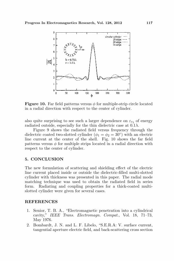
Figure 10. Far field patterns versus φ for multiple-strip circle locatedin a radial direction with respect to the center of cylinder.
also quite surprising to see such a larger dependence on εr2 of energyradiated outside, especially for the thin dielectric case at 0.1λ.
Figure 9 shows the radiated field versus frequency through thedielectric coated two-slotted cylinder (φ1 = φ2 = 30◦) with an electricline current at the center of the shell. Fig. 10 shows the far fieldpatterns versus φ for multiple strips located in a radial direction withrespect to the center of cylinder.
5. CONCLUSION
The new formulation of scattering and shielding effect of the electricline current placed inside or outside the dielectric-filled multi-slottedcylinder with thickness was presented in this paper. The radial modematching technique was used to obtain the radiated field in seriesform. Radiating and coupling properties for a thick-coated multi-slotted cylinder were given for several cases.
REFERENCES
1. Senior, T. B. A., “Electromagnetic penetration into a cylindricalcavity,” IEEE Trans. Electromagn. Compat., Vol. 18, 71–73,May 1976.
2. Bombardt, J. N. and L. F. Libelo, “S.E.R.A: V. surface current,tangential aperture electric field, and back-scattering cross section
118 Lee et al.
for axial slotted cylinder at normal, symmetric incidence,” Tech.Rep. VSURFWPNCEN, NSWC/WOL/TR, 75–39, White OakLab., Apr. 1975.
3. Hussein, M. I. and M. Hamid, “Scattering by a perfectlyconducting cylinder with an axial infinite slot,” Proc. Int.Symp. Recent Advances in Microwave Techniques ISRAMT91,Aug. 1992.
4. Hussein, M. I. and M. Hamid, “Scattering by a perfectlyconducting multislotted cylinder,” Can. Journal of Physics.,Vol. 70, 55–61, 1992.
5. Kabalan, K. Y., A. El-Haji, and R. F. Harrington, “Characteristicmodes of a slot in a conducting cylinder and their use forpenetration and scattering, TM case,” IEE Proceedings-H,Vol. 139, No. 3, 287–291, Jun. 1992.
6. El-Haji, A. and K. Y. Kabalan, “Scattering from andpenetration into a dielectric-filled conducting cylinder withmultiple apertures,” IEEE Trans. Electromagn. Compat., Vol. 36,No. 3, 196–200, Aug. 1994.
7. Colak, D., A. I. Nosich, and A. Altintas, “Radar cross-sectionstudy of cylindrical cavity-backed apertures with outer or innermaterial coating: The case of E-polarization,” IEEE Trans.Antennas Propag., Vol. 41, No. 11, 1551–1559, Nov. 1993.
8. Colak, D., A. I. Nosich, and A. Altintas, “Radar cross-sectionstudy of cylindrical cavity-backed apertures with outer or innermaterial coating: The case of H-polarization,” IEEE Trans.Antennas Propag., Vol. 43, No. 5, 440–447, May 1995.
9. Cwik, T., “Coupling into and scattering from cylindricalstructures covered periodically with matallic patches,” IEEETrans. Antennas Propag., Vol. 38, Feb. 1990.
10. Hong, W. and Z. Zhu, “Radar cross-section of dielectric-coatedconducting cylinder loaded with periodic metallic strips usingmixed SDM, CGM, and FFT: TE incidence,” IEE Proceedings-H, Vol. 140, No. 5, 373–377, Oct. 1993.
11. Arvas, E. and T. Sarkar, “TM transmission through dielectric-filled slots in a conducting cylindrical shell of arbitrary crosssection,” IEEE Trans. Electromagn. Compat., Vol. 29, 150–156,May 1987.
12. Tsalamengas, J. L., “Direct singular integral equation methodsin scattering from strip-loaded dielectric cylinders,” Journal ofElectromagnetic Wave and Applications, Vol. 10, No. 10, 1331–1358, 1996.
Progress In Electromagnetics Research, Vol. 128, 2012 119
13. Hayashi, Y., “A singular integral equation approach toelectromagnetic fields for circular boundaries with slots,” Appl.Sci. Res., Vol. B12, 331–359, 1965.
14. Koshparenok, V. N. and V. P. Shestopalov, “Diffraction of a planeelectromagnetic wave by a circular cylinder with a longitudinalslot,” USSR Comp. Math. and Math. Phys., Vol. 11, 222–243,1971.
15. Ziolkowski, R. W., W. A. Johnson, and K. F. Casey, “Applicationof Riemann-Hilbert problem techniques to electromagneticcoupling through apertures,” Radio Sci., Vol. 19, 1425–1431,Nov.–Dec. 1984.
16. Ziolkowski, R. W. and J. B. Grant, “Scattering from cavitybacked apertures: The generalized dual series solution of theconcentrically loaded E-pol slit cylinder problem,” IEEE Trans.Antennas Propag., Vol. 35, 504–528, May 1987.
17. Mautz, J. R. and R. F. Harrington, “Electromagnetic penetrationinto a conducting circular cylinder through a narrow slot, TEcase,” Journal of Electromagnetic Wave and Applications, Vol. 3,No. 4, 307–336, 1989.
18. Arvas, E., “Electromagnetic diffraction from a dielectric-filled slit-cylinder enclosing a cylinder of arbitrary cross section: TM case,”IEEE Trans. Electromagn. Compat., Vol. 31, 91–102, Feb. 1989.
19. Qin, S.-T., S.-X. Gong, R. Wang, and L.-X. Guo, “A Tdie/TDPOhybrid method for the analysis of TM transient scattering fromtwo-dimensional combinative conducting cylinders,” Progress InElectromagnetics Research, Vol. 102, 181–195, 2010.
20. Dumin, O. M., O. O. Dumina, and V. A. Katrich, “Evalutionof transient electromagnetic fields in radially inhomogeneousnonstationary medium,” Progress In Electromagnetics Research,Vol. 103, 403–418, 2010.
21. Bucinskas, J., L. Nickelson, and V. Sugurovas, “Microwavescattering and absorption by a multilayered lossy metamaterial —Glass cylinder,” Progress In Electromagnetics Research, Vol. 105,103–118, 2010.
22. Bucinskas, J., L. Nickelson, and V. Sugurovas, “Microwavediffraction characteristic analysis of 2D multilayered uniaxialanisotropic cylinder,” Progress In Electromagnetics Research,Vol. 109, 175–190, 2010.
23. Sirenko, K., V. Pazynin, Y. K. Sirenko, and H. Bagci, “An FFT-accelerated FDTD scheme with exact absorbing conditions forcharacterizing axially symmetric resonant structures,” Progress InElectromagnetics Research, Vol. 111, 331–364, 2011.

120 Lee et al.
24. Bui, V. P., X. C. Wei, E. P. Li, and W. J. Zhao, “Anefficient hybrid technique for analysis of the electromagneticfield distribution inside a closed environment,” Progress InElectromagnetics Research, Vol. 114, 301–315, 2011.
25. Ashraf, M. A. and A. A. Rizvi, “Electromagnetic scatteringfrom a random cylinder by moments method,” Journal ofElectromagnetic Wave and Applications, Vol. 25, No. 4, 467–480,2011.
26. Zubair, M., M. J. Mughal, and Q. A. Naqvi, “An exactsolution of the cylindrical wave equation for electromagnetic fieldin fractional dimensional space,” Progress In ElectromagneticsResearch, Vol. 114, 443–455, 2011.
27. Tan, W., W. Hong, Y. Wang, and Y. Wu, “A novel spherical-wavethree-dimensional imaging algorithm for microwave cylindricalscanning geometries,” Progress In Electromagnetics Research,Vol. 111, 43–70, 2011.
28. Jandieri, V., K. Yasumoto, and Y.-K. Cho, “Rigorous analysisof electromagnetic scattering by cylindrical EBG structures,”Progress In Electromagnetics Research, Vol. 121, 317–342, 2011.
29. Park, J. E., K. Y. Kim, and J.-W. Song, “Resonant powertransmission trough coupled subwavelength ridged circularapertures,” Journal of Electromagnetic Wave and Applications,Vol. 26, No. 4, 423–435, 2012.