IS-1825xSRH, IS-825xSEH, ISL71823xSRH Datasheet · INV NON-INV E/A OUT CLK/LEB RT CT RAMP 9 10 12...
25
FN9065 Rev.7.00 Page 1 of 25 Dec 15, 2017 FN9065 Rev.7.00 Dec 15, 2017 IS-1825xSRH, IS-1825BSEH, ISL71823xSRH Single Event and Total Dose Hardened, High-Speed Dual Output PWMs DATASHEET The IS-1825ASRH , IS-1825BSRH , IS-1825BSEH , ISL71823ASRH , and ISL71823BSRH are single event and total dose hardened pulse width modulators designed to be used in high-frequency switching power supplies in either voltage or current-mode configurations. These devices include a precision voltage reference, a low power start-up circuit, a high-frequency oscillator, a wide-band error amplifier, and a fast current-limit comparator. The IS-1825xSRH and IS-1825xSEH feature dual, alternating output operating from zero to less than 50% duty cycle, and the ISL71823xSRH features dual in-phase output operating from zero to less than 100% duty cycle. The B versions of the parts test the delay from clock out to PWM output switching after power has been applied to the modulator (t PWM ) (see Figure 2 on page 9 ). The SEH parts are wafer-by-wafer acceptance tested to 50krad(Si) at a low dose rate of <10mrad(Si)/s. Constructed with the Rad-hard Silicon Gate (RSG) dielectrically isolated BiCMOS process, these devices are immune to single-event latch-up and have been specifically designed to provide a high level of immunity to single-event transients. All specified parameters are established and tested for 300krad(Si) total dose performance. The devices are offered in a 16 Ld CDIP or a 20 Ld CDFP and fully specified to across the temperature range of -50°C to +125°C. Applications • Voltage or current mode switching power supplies • Control of high current MOSFET drivers • Motor speed and direction control Features • Electrically screened to DLA SMD 5962-02511 • QML qualified per MIL-PRF-38535 requirements • EH version is wafer-by-wafer acceptance tested to 50krad(Si) LDR • Oscillator frequency: 1MHz (max) • High output drive current: 1A peak (typ) • Low startup current: 300µA (max) • Undervoltage Lockout • Start threshold: 8.8V (max) • Stop threshold: 7.6V (min) • Hysteresis: 300mV (min) • Pulse-by-pulse current limiting • Programmable leading edge blanking • Radiation Hardness • High Dose Rate (HDR) (50-300rad(Si)/s): 300krad(Si) • Low Lose Rate (LDR) (0.01rad(Si)/s): 50krad(Si) • Latch-up immune (dielectrically isolated) • SEU immune: LET= 35MeV•cm 2 /mg Related Literature • For a full list of related documents, visit our website • IS-1825ASRH , IS-1825BSRH , IS-1825BSEH , ISL71823ASRH , and ISL71823BSRH product pages Table 1. Key Differences Between Family of Parts Part Number Dual Outputs Radiation Hardened Assurance Testing Clock-to-PWM Startup Test TID HDR Rating (50-300 rad(Si)/s) TID LDR Rating (<10mrad(Si)/s) IS-1825ASRH Out of Phase 300krad(Si) - - IS-1825BSRH Out of Phase 300krad(Si) - Yes IS-1825BSEH Out of Phase 300krad(Si) 50krad(Si) Yes ISL71823ASRH In Phase 300krad(Si) - - ISL71823BSRH In Phase 300krad(Si) - Yes
Transcript of IS-1825xSRH, IS-825xSEH, ISL71823xSRH Datasheet · INV NON-INV E/A OUT CLK/LEB RT CT RAMP 9 10 12...

FN9065 Rev.7.00 Page 1 of 25Dec 15, 2017
FN9065Rev.7.00
Dec 15, 2017
IS-1825xSRH, IS-1825BSEH, ISL71823xSRHSingle Event and Total Dose Hardened, High-Speed Dual Output PWMs
DATASHEET
The IS-1825ASRH, IS-1825BSRH, IS-1825BSEH, ISL71823ASRH, and ISL71823BSRH are single event and total dose hardened pulse width modulators designed to be used in high-frequency switching power supplies in either voltage or current-mode configurations. These devices include a precision voltage reference, a low power start-up circuit, a high-frequency oscillator, a wide-band error amplifier, and a fast current-limit comparator.
The IS-1825xSRH and IS-1825xSEH feature dual, alternating output operating from zero to less than 50% duty cycle, and the ISL71823xSRH features dual in-phase output operating from zero to less than 100% duty cycle. The B versions of the parts test the delay from clock out to PWM output switching after power has been applied to the modulator (tPWM) (see Figure 2 on page 9). The SEH parts are wafer-by-wafer acceptance tested to 50krad(Si) at a low dose rate of <10mrad(Si)/s.
Constructed with the Rad-hard Silicon Gate (RSG) dielectrically isolated BiCMOS process, these devices are immune to single-event latch-up and have been specifically designed to provide a high level of immunity to single-event transients. All specified parameters are established and tested for 300krad(Si) total dose performance.
The devices are offered in a 16 Ld CDIP or a 20 Ld CDFP and fully specified to across the temperature range of -50°C to +125°C.
Applications• Voltage or current mode switching power supplies
• Control of high current MOSFET drivers
• Motor speed and direction control
Features• Electrically screened to DLA SMD 5962-02511
• QML qualified per MIL-PRF-38535 requirements
• EH version is wafer-by-wafer acceptance tested to 50krad(Si) LDR
• Oscillator frequency: 1MHz (max)
• High output drive current: 1A peak (typ)
• Low startup current: 300µA (max)
• Undervoltage Lockout
• Start threshold: 8.8V (max)
• Stop threshold: 7.6V (min)
• Hysteresis: 300mV (min)
• Pulse-by-pulse current limiting
• Programmable leading edge blanking
• Radiation Hardness
• High Dose Rate (HDR) (50-300rad(Si)/s): 300krad(Si)
• Low Lose Rate (LDR) (0.01rad(Si)/s): 50krad(Si)
• Latch-up immune (dielectrically isolated)
• SEU immune: LET= 35MeV•cm2/mg
Related Literature• For a full list of related documents, visit our website
• IS-1825ASRH, IS-1825BSRH, IS-1825BSEH, ISL71823ASRH, and ISL71823BSRH product pages
Table 1. Key Differences Between Family of Parts
Part Number Dual Outputs
Radiation Hardened Assurance Testing
Clock-to-PWMStartup Test
TID HDR Rating(50-300 rad(Si)/s)
TID LDR Rating(<10mrad(Si)/s)
IS-1825ASRH Out of Phase 300krad(Si) - -
IS-1825BSRH Out of Phase 300krad(Si) - Yes
IS-1825BSEH Out of Phase 300krad(Si) 50krad(Si) Yes
ISL71823ASRH In Phase 300krad(Si) - -
ISL71823BSRH In Phase 300krad(Si) - Yes
FN9065 Rev.7.00 Page 2 of 25Dec 15, 2017
IS-1825xSRH, IS-1825BSEH, ISL71823xSRH
Contents
1. Overview. . . . . . . . . . . . . . . . . . . . . . . . . . . . . . . . . . . . . . . . . . . . . . . . . . . . . . . . . . . . . . . . . . . . . 3
1.1 Functional Block Diagram . . . . . . . . . . . . . . . . . . . . . . . . . . . . . . . . . . . . . . . . . . . . . . . . . . . . . 3
1.2 Ordering Information . . . . . . . . . . . . . . . . . . . . . . . . . . . . . . . . . . . . . . . . . . . . . . . . . . . . . . . . . 4
1.3 Pin Configuration . . . . . . . . . . . . . . . . . . . . . . . . . . . . . . . . . . . . . . . . . . . . . . . . . . . . . . . . . . . . 5
1.4 Pin Descriptions. . . . . . . . . . . . . . . . . . . . . . . . . . . . . . . . . . . . . . . . . . . . . . . . . . . . . . . . . . . . . 5
2. Specifications. . . . . . . . . . . . . . . . . . . . . . . . . . . . . . . . . . . . . . . . . . . . . . . . . . . . . . . . . . . . . . . . . 6
2.1 Absolute Maximum Ratings . . . . . . . . . . . . . . . . . . . . . . . . . . . . . . . . . . . . . . . . . . . . . . . . . . . . 6
2.2 Thermal Information. . . . . . . . . . . . . . . . . . . . . . . . . . . . . . . . . . . . . . . . . . . . . . . . . . . . . . . . . . 6
2.3 Recommended Operating Conditions . . . . . . . . . . . . . . . . . . . . . . . . . . . . . . . . . . . . . . . . . . . . 6
2.4 Electrical Specifications . . . . . . . . . . . . . . . . . . . . . . . . . . . . . . . . . . . . . . . . . . . . . . . . . . . . . . . 7
2.5 Timing Diagram . . . . . . . . . . . . . . . . . . . . . . . . . . . . . . . . . . . . . . . . . . . . . . . . . . . . . . . . . . . . . 9
3. Typical Performance Curves. . . . . . . . . . . . . . . . . . . . . . . . . . . . . . . . . . . . . . . . . . . . . . . . . . . . 10
4. Die and Assembly Characteristics . . . . . . . . . . . . . . . . . . . . . . . . . . . . . . . . . . . . . . . . . . . . . . . 19
4.1 Metallization Mask Layout . . . . . . . . . . . . . . . . . . . . . . . . . . . . . . . . . . . . . . . . . . . . . . . . . . . . 20
4.2 Bond Pad Coordinates. . . . . . . . . . . . . . . . . . . . . . . . . . . . . . . . . . . . . . . . . . . . . . . . . . . . . . . 21
5. Revision History. . . . . . . . . . . . . . . . . . . . . . . . . . . . . . . . . . . . . . . . . . . . . . . . . . . . . . . . . . . . . . 22
6. Package Outline Drawings . . . . . . . . . . . . . . . . . . . . . . . . . . . . . . . . . . . . . . . . . . . . . . . . . . . . . 23
6.1 Ceramic Metal Seal Flatpack Packages (Flatpack) . . . . . . . . . . . . . . . . . . . . . . . . . . . . . . . . . 23
6.2 Ceramic Dual-In-Line Metal Seal Packages (SBDIP) . . . . . . . . . . . . . . . . . . . . . . . . . . . . . . . 24

FN9065 Rev.7.00 Page 3 of 25Dec 15, 2017
IS-1825xSRH, IS-1825BSEH, ISL71823xSRH 1. Overview
1. Overview
1.1 Functional Block Diagram
Figure 1. Block Diagram
5.1VREFOn/Off
4VVREF
VREFHigh When VCC = OK
1.2V
0.4V
SS
RAMP
ILIM
S
R
Q
Q
5V
VCC
VREF
S
R
Q
Q
UVLO-b
Over Current
1.0V
INV
NIEA
CLK/LEB
Soft Start Charge
Soft Start Discharge
EAOUT
0.93V
RT
CT
3.0V ICT = IRT
ID5V
LEB
2.6V
VC
S
R
Q
Q
T
Q
Q
OUTB
OUTA
Current Limit
InternalBias
PGND
VC
PGND
VC
* T-FF disabled in ISL71823SxH
10k
1.0V/2.9V

FN9065 Rev.7.00 Page 4 of 25Dec 15, 2017
IS-1825xSRH, IS-1825BSEH, ISL71823xSRH 1. Overview
1.2 Ordering Information
Ordering SMDNumber (Note 1)
Part Number (Note 2)
Radiation HardnessAssurance
Temperature Range (°C)
Package(RoHS
Compliant)PackageDrawingHDR LDR
N/A IS0-1825ASRH/SAMPLE (Note 3) - - -50 to +125 DIE -
5962F0251101V9A IS0-1825ASRH-Q 300krad(Si) - -50 to +125 DIE -
5962F0251101QEC IS1-1825ASRH-8 300krad(Si) - -50 to +125 16 Ld SBDIP D16.3
5962F0251101QXC IS9-1825ASRH-8 300krad(Si) - -50 to +125 20 Ld FP K20.A
5962F0251101VEC IS1-1825ASRH-Q 300krad(Si) - -50 to +125 16 Ld SBDIP D16.3
5962F0251101VXC IS9-1825ASRH-Q 300krad(Si) - -50 to +125 20 Ld FP K20.A
N/A IS1-1825ASRH/PROTO (Note 3) - - -50 to +125 16 Ld SBDIP D16.3
N/A IS9-1825ASRH/PROTO (Note 3) - - -50 to +125 20 Ld FP K20.A
5962F0251102QEC ISL71823ASRHQD 300krad(Si) - -50 to +125 16 Ld SBDIP D16.3
5962F0251102QXC ISL71823ASRHQF 300krad(Si) - -50 to +125 20 Ld FP K20.A
5962F0251102VEC ISL71823ASRHVD 300krad(Si) - -50 to +125 16 Ld SBDIP D16.3
5962F0251102VXC ISL71823ASRHVF 300krad(Si) - -50 to +125 20 Ld FP K20.A
5962F0251102V9A ISL71823ASRHVX 300krad(Si) - -50 to +125 DIE -
N/A ISL71823ASRHD/PROTO (Note 3) - - -50 to +125 16 Ld SBDIP D16.3
N/A ISL71823ASRHF/PROTO (Note 3) - - -50 to +125 20 Ld FP K20.A
N/A ISL71823ASRHX/SAMPLE (Note 3) - - -50 to +125 DIE -
5962F0251103V9A IS0-1825BSRH-Q 300krad(Si) - -50 to +125 DIE -
5962F0251103QEC IS1-1825BSRH-8 300krad(Si) - -50 to +125 16 Ld SBDIP D16.3
5962F0251103QXC IS9-1825BSRH-8 300krad(Si) - -50 to +125 20 Ld FP K20.A
5962F0251103VEC IS1-1825BSRH-Q 300krad(Si) - -50 to +125 16 Ld SBDIP D16.3
5962F0251103VXC IS9-1825BSRH-Q 300krad(Si) - -50 to +125 20 Ld FP K20.A
5962F0251104QEC ISL71823BSRHQD 300krad(Si) - -50 to +125 16 Ld SBDIP D16.3
5962F0251104QXC ISL71823BSRHQF 300krad(Si) - -50 to +125 20 Ld FP K20.A
5962F0251104VEC ISL71823BSRHVD 300krad(Si) - -50 to +125 16 Ld SBDIP D16.3
5962F0251104VXC ISL71823BSRHVF 300krad(Si) - -50 to +125 20 Ld FP K20.A
5962F0251104V9A ISL71823BSRHVX 300krad(Si) - -50 to +125 DIE -
5962F0251105V9A IS0-1825BSEH-Q 300krad(Si) 50krad(Si) -50 to +125 DIE -
5962F0251105VEC IS1-1825BSEH-Q 300krad(Si) 50krad(Si) -50 to +125 16 Ld SBDIP D16.3
5962F0251105VXC IS9-1825BSEH-Q 300krad(Si) 50krad(Si) -50 to +125 20 Ld FP K20.A
Notes:1. Specifications for Rad Hard QML devices are controlled by the Defense Logistics Agency Land and Maritime (DLA). The SMD
numbers listed must be used when ordering.2. These Pb-free Hermetic packaged products employ 100% Au plate - e4 termination finish, which is RoHS compliant and
compatible with both SnPb and Pb-free soldering operations.3. The /PROTO and /SAMPLE are not rated or certified for Total Ionizing Dose (TID) or Single Event Effect (SEE) immunity. These
parts are intended for engineering evaluation purposes only. The /PROTO parts meet the electrical limits and conditions across the temperature range specified in the DLA SMD and are in the same form and fit as the qualified device. The /SAMPLE die is capable of meeting the electrical limits and conditions specified in the DLA SMD at +25°C only. The /SAMPLE is a die and does not receive 100% screening across the temperature range to the DLA SMD electrical limits. These part types do not come with a certificate of conformance because there is no radiation assurance testing and they are not DLA qualified devices.

FN9065 Rev.7.00 Page 5 of 25Dec 15, 2017
IS-1825xSRH, IS-1825BSEH, ISL71823xSRH 1. Overview
1.3 Pin Configuration
1.4 Pin Descriptions
IS1-1825ASRH, IS1-1825BSRH, IS-1825BSEHISL71823BSRHVD, ISL71823ASRHQD
(CDIP2-T16 SBDIP)TOP VIEW
IS9-1825ASRH, IS9-1825BSRH, IS9-1825BSEHISL71823ASRHQF, ISL71823BSRHVF
(CDFP4-F20 FLATPACK)TOP VIEW
Pin Name
Pin Number
DescriptionSBDIP Flatpack
INV 1 2 Inverting input for the error amplifier.
NON-INV 2 3 Non inverting input for the error amplifier.
E/A OUT 3 4 Error amplifier output.
CLK/LEB 4 5 Clock out pin with leading edge blanking.
RT 5 6 Timing resistor pin for programming the oscillator.
CT 6 7 Timing capacitor pin for programming the oscillator.
RAMP 7 8 Non inverting input to the PWM comparator with a 1.25V internal offset.
SS 8 9 Soft-Start pin for controlling startup ramp time and inrush current.
ILIM/SD 9 11 Input to the current limit comparator.
GND 10 12 Ground return for the analog circuitry.
OUTA 11 13 High current totem pole output of the driver stage.
PGND 12 14, 17 Ground return for the output driver stage.
VC 13 15, 16 Power supply pin for the output stage. Bypass this pin with a 0.1µF capacitor with low ESL and minimize the trace length by placing it as close to the pin as possible.
OUTB 14 18 High current totem pole output of the driver stage.
VCC 15 19 Power supply pin for the device. Bypass this pin with a 0.1µF capacitor with low ESL and minimize the trace length by placing it as close to the pin as possible.
VREF 16 20 5.1V voltage reference.
NC - 1, 10 Not electrically connected.
14
15
16
9
13
12
11
10
1
2
3
4
5
7
6
8
INV
NON-INV
E/A OUT
CLK/LEB
RT
CT
SS
RAMP
VREF
OUT B
VC
PGND
OUT A
GND
ILIM/SD
VCC2
3
4
5
6
7
8
1 20
19
18
17
16
15
14
13
NC
INV
NON-INV
E/A OUT
CLK/LEB
RT
CT
RAMP
9
10
12
11
SS
NC
VREF
VCC
OUT B
PGND
VC
VC
PGND
OUT A
GND
ILIM/SD

FN9065 Rev.7.00 Page 6 of 25Dec 15, 2017
IS-1825xSRH, IS-1825BSEH, ISL71823xSRH 2. Specifications
2. Specifications
2.1 Absolute Maximum Ratings
2.2 Thermal Information
2.3 Recommended Operating Conditions
Parameter Minimum Maximum Unit
VC, VCC - 35 V
Analog Inputs (INV, NON-INV, RAMP, ILIM/SD, SS) -0.3 VCC + 0.3 V
Power Dissipation - 714 mW
CAUTION: Do not operate at or near the maximum ratings listed for extended periods of time. Exposure to such conditions may adversely impact product reliability and result in failures not covered by warranty.
Thermal Resistance (Typical) JA (°C/W) JC (°C/W)
CDIP Package D16.3 (Notes 4, 5) 70 18
CDFP Package K20.A (Notes 4, 5) 80 15
Notes:4. JA is measured with the component mounted on a high-effective thermal conductivity test board in free air. See TB379.5. For JC, the “case temp” location is the center of the package underside.
Parameter Minimum Maximum Unit
Maximum Junction Temperature +175 °C
Storage Temperature Range -65 +150 °C
Lead Temperature (Soldering 10 seconds) - +260 °C
Parameter Minimum Maximum Unit
Temperature -50 +125 °C
VC, VCC 12 20 V

FN9065 Rev.7.00 Page 7 of 25Dec 15, 2017
IS-1825xSRH, IS-1825BSEH, ISL71823xSRH 2. Specifications
2.4 Electrical Specifications
Unless otherwise noted, VS = VC = VCC = 12V, RT=3.65kΩ, CT=1nF, TA = +25°C. Boldface limits apply across the operating temperature range, -50°C to +125°C; over a total ionizing dose of 300krad(Si) with exposure at a high dose rate of 50 to 300rad(Si)/s; or over a total ionizing dose of 75krad(Si) with exposure at a low dose rate of <10mrad(Si)/s (SEH devices only).
Parameter Symbol Test ConditionsMin
(Note 7) TypMax
(Note 7) Unit
Reference Section
Output Voltage VREF 5.00 5.10 5.20 V
4.92 - 5.28 V
Line Regulation VLINE 12.0V < VS < 20.0V -15 6.2 15 mV
-20 - 20 mV
Load Regulation VLOAD 1.0mA < IOUT < 10.0mA -25 2.7 25 mV
50 - 50 mV
Total Output Variation VOM VS = 12.0V, 20.0V, IOUT = 1.0mA, 10.0mA
5.00 5.10 5.20 V
4.92 - 5.28 V
Short Circuit Current ISC VREF = 0V 30 64 - mA
20 - -
Oscillator Section
Initial Accuracy FO 340 379 425 kHz
300 - 425 kHz
Voltage Stability FPSRR 12.0V < VS < 20.0V, TA = +25°C -3 -0.4 3 %
12.0V < VS < 20.0V, TA = -55°C, +125°C -5 - 5 %
12.0V < VS < 20.0V, TA = +25°C, Post Rad -3 - 3 %
Total Variation FOM VS = 12.0V, 20.0V 340 366 425 kHz
300 - 425 kHz
Clock Out High Voltage VCLKH 4.00 4.41 - V
3.75 - - V
Clock Out Low Voltage VCLKL - 5.8 200 mV
CT Ramp Peak Voltage VCT(PEAK) - 2.9 - V
CT Ramp Valley Voltage VCT(VALLEY) - 1.0 - V
Error Amplifier Section
Input Offset Voltage VOS VCM = 3.0V, VO = 3.0V -10 0.66 10 mV
Input Bias Current IIBAS VCM = 3.0V, VO = 3.0V -2 -0.44 2 µA
Input Offset Current IOS VCM = 3.0V, VO = 3.0V -2 0.07 2 µA
Open Loop Gain AVOL 1.0V < VO < 4.0V 60 117 - dB
Common Mode Rejection Ratio CMRR 1.5V < VCM < 4.0V, TA = +25°C 65 100 - dB
1.5V < VCM < 4.0V, TA = -55°C, +125°C 45 - - dB
1.5V < VCM < 4.0V, TA = +25°C, Post Rad 65 - - dB
Power Supply Rejection Ratio PSRR 12.0V < VS < 20.0V 70 119 - dB
Gain-Bandwidth Product GBWP - 13 - MHz
Output Sink Current IOL VE/A OUT = 1.0V 1 11 - mA
Output Source Current IOH VE/A OUT = 4.0V -0.5 -9 - mA
Output High Voltage VE/A OH IE/A OUT = -0.5mA 4 4.6 - V

FN9065 Rev.7.00 Page 8 of 25Dec 15, 2017
IS-1825xSRH, IS-1825BSEH, ISL71823xSRH 2. Specifications
Output Low Voltage VE/A OL IE/A OUT = 1.0 mA - 0.6 1.0 V
Rising Slew Rate SRR - 12 - V/µs
Falling Slew Rate SRF - 14 - V/µs
Pulse Width Modulator (PWM) Comparator Section
Ramp Bias Current IRAMP VRAMP = 0V - -0.2 -8 µA
Duty Cycle Range DCMAX IS-1825xSRH, IS-1825xSEH 40 44 - %
ISL71823xSRH 80 90 - %
E/A OUT Zero DC Threshold Voltage RAMPOFFSET VRAMP = 0V 0.81 0.93 - V
Delay to Output Time tDELAY VE/A OUT = 0V to 5V Step - 600 - ns
Soft Start Section
Charge Current ICHG VSS = 2.5V, TA = +25°C 8 15 20 µA
VSS = 2.5V, TA = +125°C 8 - 25 µA
VSS = 2.5V, TA = -55°C 8 - 29 µA
VSS = 2.5V, TA = +25°C, Post Rad 8 - 25 µA
Discharge Current IDCHG Soft start voltage = 2.5V 0.1 0.2 0.5 mA
Current Limit / Start Sequence / Fault Section
Restart Threshold VRS - 0.4 0.5 V
ILIM Bias Current IBLIM 0.0V < VILIM < 2.0V - 1.4 15 µA
Current Limit Threshold VLIMIT 0.85 0.98 1.15 V
Over Current Threshold VOVER 1.05 1.18 1.26 V
Current Limit Delay tILIMIT-DEL - 180 - ns
Over Current Delay tOVER-DEL - 100 - ns
Output Section
Output Low Saturation VSATL IOUT = 20mA, TA = +25°C - 0.7 0.8 V
IOUT = 20mA, TA = -55°C, +125°C - - 1.0 V
IOUT = 20mA, TA = +25°C, Post Rad - - 0.8 V
IOUT = 200 mA - 1.0 2.2 V
Output High Saturation VSATH IOUT = 20mA 10 11.2 - V
IOUT = 200 mA 9 10.8 - V
Under Voltage Lockout (UVLO) Output Low Saturation Voltage
UVLOOLS IOUT = 20mA - 0.7 1.2 V
Clock Out to PWM Switching Startup Delay (See Figure 2) (IS-1825BSxH andISL71823BSRH only)
tPWM TA = +25°C 200 291 380 µs
TA = +125°C 400 - 660 µs
TA = -55°C 100 - 278 µs
TA = +25°C, Post Rad 200 - 380 µs
Under Voltage Section
Start Threshold Voltage VSTART 8.2 8.6 8.8 V
Stop Threshold Voltage VSTOP 7.6 8.0 8.4 V
Under Voltage Lockout Hysteresis VHYS 0.3 0.6 1.2 V
Unless otherwise noted, VS = VC = VCC = 12V, RT=3.65kΩ, CT=1nF, TA = +25°C. Boldface limits apply across the operating temperature range, -50°C to +125°C; over a total ionizing dose of 300krad(Si) with exposure at a high dose rate of 50 to 300rad(Si)/s; or over a total ionizing dose of 75krad(Si) with exposure at a low dose rate of <10mrad(Si)/s (SEH devices only).
Parameter Symbol Test ConditionsMin
(Note 7) TypMax
(Note 7) Unit

FN9065 Rev.7.00 Page 9 of 25Dec 15, 2017
IS-1825xSRH, IS-1825BSEH, ISL71823xSRH 2. Specifications
2.5 Timing Diagram
Figure 2. Timing Diagram for Clock Out to PWM Switching Delay Test (tPWM)
Supply Current Section
Startup Current ISU VS = 8.0V - 55 300 µA
Supply Current ICC VINV = VRAMP = VILIM/SD = 0.0VVNON-INV = 1.0V
- 25 36 mA
Notes:6. Typical values shown are not guaranteed.7. Parameters with MIN and/or MAX limits are 100% tested at -50°C, +25°C, and +125°C, unless otherwise specified.8. VC and VCC must always be at the same potential.
Unless otherwise noted, VS = VC = VCC = 12V, RT=3.65kΩ, CT=1nF, TA = +25°C. Boldface limits apply across the operating temperature range, -50°C to +125°C; over a total ionizing dose of 300krad(Si) with exposure at a high dose rate of 50 to 300rad(Si)/s; or over a total ionizing dose of 75krad(Si) with exposure at a low dose rate of <10mrad(Si)/s (SEH devices only).
Parameter Symbol Test ConditionsMin
(Note 7) TypMax
(Note 7) Unit
0V
12V
0V
0V
VC, VCC
CLK
OUTA/B
tPWM

FN9065 Rev.7.00 Page 10 of 25Dec 15, 2017
IS-1825xSRH, IS-1825BSEH, ISL71823xSRH 3. Typical Performance Curves
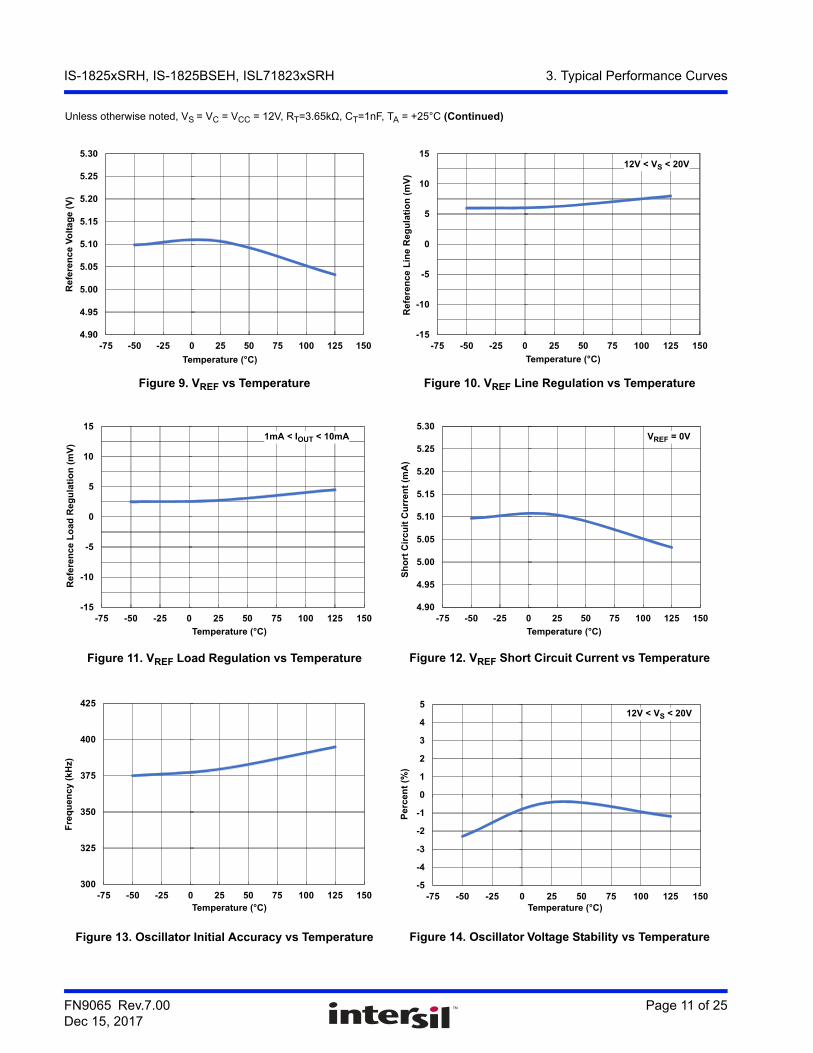
3. Typical Performance CurvesUnless otherwise noted, VS = VC = VCC = 12V, RT=3.65kΩ, CT=1nF, TA = +25°C
Figure 3. Oscillator Frequency vs RT and CT (+25°C) Figure 4. Oscillator Frequency vs RT and CT (+125°C)
Figure 5. Oscillator Frequency vs RT and CT (-50°C) Figure 6. Maximum Duty Cycle vs RT (+25°C)
Figure 7. Maximum Duty Cycle vs RT (+125°C) Figure 8. Maximum Duty Cycle vs RT (-50°C)
1
10
100
1,000
10,000
1 10 100
RT (kΩ)
Osc
illa
tor
Fre
qu
ency
(kH
z)
2.20nF
0.22nF0.47nF
10.0nF22.0nF
4.70nF
1.00nF
1
10
100
1,000
10,000
1 10 100
RT (kΩ)
Os
cill
ato
r F
req
uen
cy (
kH
z) 2.20nF
0.22nF0.47nF
10.0nF22.0nF
4.70nF
1.00nF
1
10
100
1,000
10,000
1 10 100RT (kΩ)
Os
cill
ato
r F
req
ue
nc
y (k
Hz) 2.20nF
0.22nF0.47nF
10.0nF22.0nF
4.70nF
1.00nF
15
20
25
30
35
40
45
50
55
1 10 100
Ma
xim
um
Du
ty C
yc
le (
%)
RT (kΩ)
15
20
25
30
35
40
45
50
55
1 10 100RT (kΩ)
Max
imu
m D
uty
Cy
cle
(%
)
15
20
25
30
35
40
45
50
55
1 10 100RT (kΩ)
Ma
xim
um
Du
ty C
yc
le (
%)
FN9065 Rev.7.00 Page 11 of 25Dec 15, 2017
IS-1825xSRH, IS-1825BSEH, ISL71823xSRH 3. Typical Performance Curves
Figure 9. VREF vs Temperature Figure 10. VREF Line Regulation vs Temperature
Figure 11. VREF Load Regulation vs Temperature Figure 12. VREF Short Circuit Current vs Temperature
Figure 13. Oscillator Initial Accuracy vs Temperature Figure 14. Oscillator Voltage Stability vs Temperature
Unless otherwise noted, VS = VC = VCC = 12V, RT=3.65kΩ, CT=1nF, TA = +25°C (Continued)
4.90
4.95
5.00
5.05
5.10
5.15
5.20
5.25
5.30
-75 -50 -25 0 25 50 75 100 125 150
Temperature (°C)
Re
fere
nc
e V
olt
ag
e (
V)
-15
-10
-5
0
5
10
15
-75 -50 -25 0 25 50 75 100 125 150
Temperature (°C)
Ref
eren
ce L
ine
Reg
ula
tio
n (
mV
)
12V < VS < 20V
-15
-10
-5
0
5
10
15
-75 -50 -25 0 25 50 75 100 125 150
Temperature (°C)
Ref
ere
nce
Lo
ad R
egu
lati
on
(m
V)
1mA < IOUT < 10mA
4.90
4.95
5.00
5.05
5.10
5.15
5.20
5.25
5.30
-75 -50 -25 0 25 50 75 100 125 150
Temperature (°C)
Sh
ort
Cir
cuit
Cu
rren
t (m
A)
VREF = 0V
300
325
350
375
400
425
-75 -50 -25 0 25 50 75 100 125 150Temperature (°C)
Fre
qu
en
cy
(kH
z)
-5
-4
-3
-2
-1
0
1
2
3
4
5
-75 -50 -25 0 25 50 75 100 125 150Temperature (°C)
Pe
rcen
t (%
)
12V < VS < 20V

FN9065 Rev.7.00 Page 12 of 25Dec 15, 2017
IS-1825xSRH, IS-1825BSEH, ISL71823xSRH 3. Typical Performance Curves
Figure 15. Oscillator VCLKH vs Temperature Figure 16. Oscillator VCLKL vs Temperature
Figure 17. CT Valley Voltage vs Temperature Figure 18. CT Peak Voltage vs Temperature
Figure 19. Error Amp VOS vs Temperature Figure 20. Error Amp IBIAS vs Temperature
Unless otherwise noted, VS = VC = VCC = 12V, RT=3.65kΩ, CT=1nF, TA = +25°C (Continued)
4.0
4.2
4.4
4.6
4.8
5.0
-75 -50 -25 0 25 50 75 100 125 150
Temperature (°C)
Clo
ck O
ut
Hig
h V
olt
ag
e (V
)
0
1
2
3
4
5
6
7
8
9
10
-75 -50 -25 0 25 50 75 100 125 150
Clo
ck O
ut
Lo
w V
olt
ag
e (m
V)
Temperature (°C)
0
1
2
3
4
5
-75 -50 -25 0 25 50 75 100 125 150
VC
T (
V)
Temperature (°C)
0
1
2
3
4
5
-75 -50 -25 0 25 50 75 100 125 150Temperature (°C)
VC
LK
L (
V)
-10
-8
-6
-4
-2
0
2
4
6
8
10
-75 -50 -25 0 25 50 75 100 125 150
Temperature (°C)
Off
set
Vo
ltag
e (m
V)
VCM = 3.0V, VE/A OUT = 3.0V
-2.0
-1.5
-1.0
-0.5
0.0
0.5
1.0
1.5
2.0
-75 -50 -25 0 25 50 75 100 125 150
Inp
ut
Bia
s C
urr
ent
(µA
)
VCM = 3.0V, VE/A OUT = 3.0V
Temperature (°C)

FN9065 Rev.7.00 Page 13 of 25Dec 15, 2017
IS-1825xSRH, IS-1825BSEH, ISL71823xSRH 3. Typical Performance Curves
Figure 21. Error Amp IOS vs Temperature Figure 22. Error Amp AVOL vs Temperature
Figure 23. Error Amp CMRR vs Temperature Figure 24. Error Amp PSRR vs Temperature
Figure 25. Error Amp IOL vs Temperature Figure 26. Error Amp IOH vs Temperature
Unless otherwise noted, VS = VC = VCC = 12V, RT=3.65kΩ, CT=1nF, TA = +25°C (Continued)
-2.0
-1.5
-1.0
-0.5
0.0
0.5
1.0
1.5
2.0
-75 -50 -25 0 25 50 75 100 125 150
Temperature (°C)
Inp
ut
Off
set
Cu
rren
t (µ
A)
VCM = 3.0V, VE/A OUT = 3.0V
0
25
50
75
100
125
150
175
200
-75 -50 -25 0 25 50 75 100 125 150
Temperature (°C)
Op
en L
oo
p G
ain
(d
B)
1V < VE/A OUT < 4V
0
25
50
75
100
125
150
175
200
-75 -50 -25 0 25 50 75 100 125 150
Temperature (°C)
Co
mm
on
Mo
de
Rej
ecti
on
Rat
io (
dB
) 1.5V < VCM < 4V
0
25
50
75
100
125
150
175
200
-75 -50 -25 0 25 50 75 100 125 150
Temperature (°C)
Po
wer
Su
pp
ly R
ejec
tio
n R
atio
(d
B) 12V < VS < 20V
0
2
4
6
8
10
12
14
16
-75 -50 -25 0 25 50 75 100 125 150
Temperature (°C)
Ou
tpu
t S
ink
Cu
rre
nt
(mA
)
VE/A OUT = 1.0V
-16
-14
-12
-10
-8
-6
-4
-2
0
-75 -50 -25 0 25 50 75 100 125 150
VE/A OUT = 4.0V
Temperature (°C)
Ou
tpu
t S
ou
rce
Cu
rren
t (m
A)

FN9065 Rev.7.00 Page 14 of 25Dec 15, 2017
IS-1825xSRH, IS-1825BSEH, ISL71823xSRH 3. Typical Performance Curves
Figure 27. Error Amp VOH vs Temperature Figure 28. Error Amp VOL vs Temperature
Figure 29. Error Amplifier Frequency Response Figure 30. Error Amplifier GBWP vs Temperature
Figure 31. Error Amplifier Rising Slew Rate vs Temperature
Figure 32. Error Amplifier Falling Slew Rate vs Temperature
Unless otherwise noted, VS = VC = VCC = 12V, RT=3.65kΩ, CT=1nF, TA = +25°C (Continued)
4.0
4.2
4.4
4.6
4.8
5.0
-75 -50 -25 0 25 50 75 100 125 150
Temperature (°C)
Ou
tpu
t H
igh
Vo
ltag
e (V
)
IE/A OUT = -0.5mA
0
0.2
0.4
0.6
0.8
1
-75 -50 -25 0 25 50 75 100 125 150
Temperature (°C)
Ou
tpu
t L
ow
Vo
lta
ge
(V)
IE/A OUT = 1.0mA
-30
-20
-10
0
10
20
30
40
50
1K 10K 100K 1M 10M 100M
Frequency (Hz)
Ga
in (
dB
)
-50°C
+25°C
+125°C
0
5
10
15
20
-75 -50 -25 0 25 50 75 100 125 150
Temperature (°C)
Ga
in B
an
dw
idth
Pro
du
ct
(MH
z)
11.0
11.5
12.0
12.5
13.0
13.5
14.0
-75 -50 -25 0 25 50 75 100 125 150
Temperature (°C)
Sle
w R
ate
(V
/µs
)
13.0
13.5
14.0
14.5
15.0
15.5
16.0
-75 -50 -25 0 25 50 75 100 125 150
Temperature (°C)
Sle
w R
ate
(V
/µs
)

FN9065 Rev.7.00 Page 15 of 25Dec 15, 2017
IS-1825xSRH, IS-1825BSEH, ISL71823xSRH 3. Typical Performance Curves
Figure 33. Ramp Bias Current vs Temperature Figure 34. Maximum Duty Cycle vs Temperature
Figure 35. Maximum Duty Cycle vs Temperature Figure 36. Ramp Offset vs Temperature
Figure 37. Clock to PWM Startup Delay vs Temperature Figure 38. PWM Comparator to OUT Delay vs Temperature
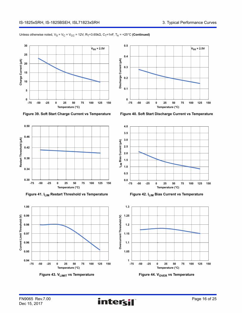
Unless otherwise noted, VS = VC = VCC = 12V, RT=3.65kΩ, CT=1nF, TA = +25°C (Continued)
-2.0
-1.5
-1.0
-0.5
0.0
0.5
1.0
1.5
2.0
-75 -50 -25 0 25 50 75 100 125 150
Temperature (°C)
Ra
mp
Bia
s C
urr
en
t (µ
A)
VRAMP = 0V
25
30
35
40
45
50
-75 -50 -25 0 25 50 75 100 125 150
Temperature (°C)
Du
ty C
ycle
(%
)
IS-1825xSRH, IS-1825xSEH
75
80
85
90
95
100
-75 -50 -25 0 25 50 75 100 125 150
Temperature (°C)
ISL71823xSRH
Du
ty C
yc
le (
%)
0.80
0.85
0.90
0.95
1.00
1.05
1.10
1.15
1.20
-75 -50 -25 0 25 50 75 100 125 150
Temperature (°C)
Ra
mp
Off
set
Vo
lta
ge
(V)
0
100
200
300
400
500
600
-75 -50 -25 0 25 50 75 100 125 150
Temperature (°C)
Sta
rtu
p T
ime
(µ
s)
0
200
400
600
800
1000
-75 -50 -25 0 25 50 75 100 125 150
Temperature (°C)
t DE
LA
Y (
ns
)
FN9065 Rev.7.00 Page 16 of 25Dec 15, 2017
IS-1825xSRH, IS-1825BSEH, ISL71823xSRH 3. Typical Performance Curves
Figure 39. Soft Start Charge Current vs Temperature Figure 40. Soft Start Discharge Current vs Temperature
Figure 41. ILIM Restart Threshold vs Temperature Figure 42. ILIM Bias Current vs Temperature
Figure 43. VLIMIT vs Temperature Figure 44. VOVER vs Temperature
Unless otherwise noted, VS = VC = VCC = 12V, RT=3.65kΩ, CT=1nF, TA = +25°C (Continued)
0
5
10
15
20
25
30
-75 -50 -25 0 25 50 75 100 125 150
Temperature (°C)
Ch
arg
e C
urr
ent
(µA
)
VSS = 2.5V
0
0.1
0.2
0.3
0.4
0.5
-75 -50 -25 0 25 50 75 100 125 150
Temperature (°C)
Dis
ch
arg
e C
urr
ent
(µA
)
VSS = 2.5V
0.30
0.34
0.38
0.42
0.46
0.50
-75 -50 -25 0 25 50 75 100 125 150
Temperature (°C)
Res
tart
Th
res
ho
ld (
µA
)
0.0
0.5
1.0
1.5
2.0
2.5
3.0
3.5
4.0
-75 -50 -25 0 25 50 75 100 125 150
Temperature (°C)
I LIM
Bia
s C
urr
ent
(µA
)
0.94
0.95
0.96
0.97
0.98
0.99
1.00
-75 -50 -25 0 25 50 75 100 125 150
Temperature (°C)
Cu
rre
nt
Lim
it T
hre
sh
old
(V
)
1
1.05
1.1
1.15
1.2
1.25
1.3
-75 -50 -25 0 25 50 75 100 125 150
Temperature (°C)
Ov
erc
urr
en
t T
hre
sh
old
(V
)

FN9065 Rev.7.00 Page 17 of 25Dec 15, 2017
IS-1825xSRH, IS-1825BSEH, ISL71823xSRH 3. Typical Performance Curves
Figure 45. Current Limit Delay vs Temperature Figure 46. Overcurrent Delay vs Temperature
Figure 47. VSATL vs Temperature Figure 48. VSATH vs Temperature
Figure 49. UVLOOLS vs Temperature Figure 50. VSTART vs Temperature
Unless otherwise noted, VS = VC = VCC = 12V, RT=3.65kΩ, CT=1nF, TA = +25°C (Continued)
0
50
100
150
200
250
300
350
400
-75 -50 -25 0 25 50 75 100 125 150Temperature (°C)
Cu
rre
nt
Lim
it D
ela
y (
ns
)
0
50
100
150
200
250
300
350
-75 -50 -25 0 25 50 75 100 125 150
Ov
erc
urr
en
t D
elay
(n
s)
Temperature (°C)
0
0.2
0.4
0.6
0.8
1
1.2
1.4
1.6
1.8
2
-75 -50 -25 0 25 50 75 100 125 150
Temperature (°C)
PW
M O
utp
ut
Sat
ura
tio
n L
ow
(V
)
IOUT = 20mA
IOUT = 200mA
9.0
9.5
10.0
10.5
11.0
11.5
12.0
-75 -50 -25 0 25 50 75 100 125 150
Temperature (°C)
PW
M O
utp
ut
Sat
ura
tio
n H
igh
(V
)
IOUT = 20mA
IOUT = 200mA
0.0
0.2
0.4
0.6
0.8
1.0
1.2
-75 -50 -25 0 25 50 75 100 125 150
Temperature (°C)
UV
LO
Ou
tpu
t L
ow
Sat
ura
tio
n (
V) IOUT = 20mA
8.2
8.3
8.4
8.5
8.6
8.7
8.8
-75 -50 -25 0 25 50 75 100 125 150
Temperature (°C)
UV
LO
Ris
ing
Th
resh
old
(V
)

FN9065 Rev.7.00 Page 18 of 25Dec 15, 2017
IS-1825xSRH, IS-1825BSEH, ISL71823xSRH 3. Typical Performance Curves
Figure 51. VSTOP vs Temperature Figure 52. VHYS vs Temperature
Figure 53. Startup Current vs Temperature Figure 54. Supply Current vs Temperature
Unless otherwise noted, VS = VC = VCC = 12V, RT=3.65kΩ, CT=1nF, TA = +25°C (Continued)
7.6
7.7
7.8
7.9
8.0
8.1
8.2
8.3
8.4
-75 -50 -25 0 25 50 75 100 125 150
Temperature (°C)
UV
LO
Fal
lin
g T
hre
sho
ld (
V)
0
0.2
0.4
0.6
0.8
1
1.2
-75 -50 -25 0 25 50 75 100 125 150
Temperature (°C)
UV
LO
Hy
ste
res
is (
V)
0
25
50
75
100
125
150
-75 -50 -25 0 25 50 75 100 125 150
Temperature (°C)
Sta
rtu
p C
urr
ent
(µA
)
0
5
10
15
20
25
30
35
40
-75 -50 -25 0 25 50 75 100 125 150
Temperature (°C)
Su
pp
ly C
urr
ent
(mA
)

FN9065 Rev.7.00 Page 19 of 25Dec 15, 2017
IS-1825xSRH, IS-1825BSEH, ISL71823xSRH 4. Die and Assembly Characteristics
4. Die and Assembly Characteristics
Table 2. Die and Assembly Related Information
Die Information
Dimensions 4310µm x 5840µm (170 mils x 230 mils)Thickness: 483µm ±25.4µm (19 mils ±1 mil)
Interface Materials
Glassivation Type: Phosphorus Silicon Glass (PSG)Thickness: 8.0kÅ ±1.0kÅ
Top Metallization Type: AlCu (99.5%/0.5%)Thickness: 16.0kÅ ±2kÅ
Backside Finish Silicon
Process Radiation Hardened Silicon Gate, Dielectrically Isolated (DI)
Assembly Information
Substrate Potential Unbiased (DI)
Additional Information
Worst Case Current Density <2x10⁵ A/cm2
Transistor Count 585

FN9065 Rev.7.00 Page 20 of 25Dec 15, 2017
IS-1825xSRH, IS-1825BSEH, ISL71823xSRH 4. Die and Assembly Characteristics
4.1 Metallization Mask LayoutIS-1825xSRH, IS-1825xSEH, ISL71823xSRH
VC
VC
VREFINVNON-INVE/A OUTCLK/LEB
CT RAMP SS ILIM/SD OGND GND OUT A PGND
PGNDOUT BVCC
RT
RT
COORDINATE ORIGIN(Centroid of INV pad)
Notes:9. Both the OGND (oscillator ground) and the GND (control circuit ground) pads must be bonded to
ground. These pads are both bonded to the GND pin on the packaged devices.10. All double-sized bond pads must be double bonded for current sharing purposes.

FN9065 Rev.7.00 Page 21 of 25Dec 15, 2017
IS-1825xSRH, IS-1825BSEH, ISL71823xSRH 4. Die and Assembly Characteristics
4.2 Bond Pad CoordinatesTable 3. Layout X-Y Coordinates (Centroid of bond pad)
Pad Number Pad Name X (µm) Y (µm) dX (µm) dY (µm)
1 INV 0 0 110 110
2 NON-INV -173 0 110 110
3 EA/OUT -420 -5 110 110
4 CLK/LEB -788 0 110 110
5 RT -757 -5222 110 110
6 CT -387 -5205 110 110
7 RAMP 46 -5205 110 110
8 SS 232 -5235 110 110
9 ILIM/SD 563 -5235 110 110
10 OGND 783 -5180 110 110
11 GND 1004 -5235 110 110
12 OUTA 1642 -5117.5 280 109
13 PGND 2274 -5341.5 280 109
14 VC 2812 -4570.5 280 109
15 VC 2812 -683.5 280 109
16 PGND 2274 87.5 280 109
17 OUTB 1642 -136.5 280 109
18 VCC 1107 94.5 110 110
19 VREF 622 110.5 110 110

FN9065 Rev.7.00 Page 22 of 25Dec 15, 2017
IS-1825xSRH, IS-1825BSEH, ISL71823xSRH 5. Revision History
5. Revision History
Rev. Date Description
7.00 Jan 15, 2018 Updated second paragraph on page 1, changed “10mrad(Si)/s” to “<10mrad(Si)/s”.Added last paragraph on page 1.Added Table 1 on page 1.Added TOC.Updated Ordering information table by adding 2 new columns and Note 3 along with its cross reference.Added Pin Description section.Added Absolute Maximum Ratings, Thermal Information, and Recommended Operating Conditions sections.Added the Electrical Specifications table.Updated Figure 2.Added Typical Performance Curves.Added the Functional Block Diagram.Removed “About Intersil” section.Added new disclaimerConverted to the current document format.
6.00 Jan 5, 2017 Updated Related Literature on page 1.Removed ISL70417SEHVF from the ordering information table.Removed MSL note because it does not apply to hermetic packages.Updated Metallization Mask Layout.Updated About Intersil section.
5.00 Apr 23, 2013 Removed Part number IS-1825ASEH and added part numbers IS-1825BSEH, IS-1825BSRH, and ISL71823BSRH to ordering information table on page 2.SMD numbers in Ordering Information table corrected.Added timing diagram for CLK to OUT delay tPWM.
4.00 Apr 5, 2012 Updated to new Intersil template.Added Part IS-1825ASEH to Title and ordering information.Changed DSCC to DLA.Added typical oscillator performance curves. Updated ordering information by adding package, package drawing number, and sample parts.
3.00 Feb 19, 2008 Added ISL71823ASRH which is a metal option of the IS-1825ASRH.
2.00 Jun 14, 2005 Changed “u” to “µ” on pg 1 Features.
1.00 Jun 14, 2005 Removed “Trimmed Oscillator Discharge Current” from the Features section of both datasheets because the oscillator is not trimmed. Cosmetic edit only.
0.00 Jun 21, 2002 Initial release

FN9065 Rev.7.00 Page 23 of 25Dec 15, 2017
IS-1825xSRH, IS-1825BSEH, ISL71823xSRH 6. Package Outline Drawings
6. Package Outline Drawings
6.1 Ceramic Metal Seal Flatpack Packages (Flatpack)
-D-
-C-
0.004 H A - BM DS S
-A- -B-
0.036 H A - BM DS S
e
E
A
Q
L
D
A
E1
SEATING AND
LE2
E3 E3
BASE PLANE
-H-
b
C
S1
M
c1
b1
(c)
(b)
SECTION A-A
BASE
LEAD FINISH
METAL
PIN NO. 1ID AREA
A
M
K20.A MIL-STD-1835 CDFP4-F20 (F-9A, CONFIGURATION B)20 LEAD CERAMIC METAL SEAL FLATPACK PACKAGE
SYMBOL
INCHES MILLIMETERS
NOTESMIN MAX MIN MAX
A 0.045 0.115 1.14 2.92 -
b 0.015 0.022 0.38 0.56 -
b1 0.015 0.019 0.38 0.48 -
c 0.004 0.009 0.10 0.23 -
c1 0.004 0.006 0.10 0.15 -
D - 0.540 - 13.72 3
E 0.245 0.300 6.22 7.62 -
E1 - 0.330 - 8.38 3
E2 0.130 - 3.30 - -
E3 0.030 - 0.76 - 7
e 0.050 BSC 1.27 BSC -
k 0.008 0.015 0.20 0.38 2
L 0.250 0.370 6.35 9.40 -
Q 0.026 0.045 0.66 1.14 8
S1 0.00 - 0.00 - 6
M - 0.0015 - 0.04 -
N 20 20 -
Rev. 0 5/18/94
Notes:1. Index area: A notch or a pin one identification mark shall be
located adjacent to pin one and shall be located within the shaded area shown. The manufacturer’s identification shall not be used as a pin one identification mark. Alternately, a tab (dimension k) may be used to identify pin one.
2. If a pin one identification mark is used in addition to a tab, the limits of dimension k do not apply.
3. This dimension allows for off-center lid, meniscus, and glass overrun.
4. Dimensions b1 and c1 apply to lead base metal only. Dimension M applies to lead plating and finish thickness. The maximum limits of lead dimensions b and c or M shall be measured at the centroid of the finished lead surfaces, when solder dip or tin plate lead finish is applied.
5. N is the maximum number of terminal positions.6. Measure dimension S1 at all four corners.7. For bottom-brazed lead packages, no organic or polymeric
materials shall be molded to the bottom of the package to cover the leads.
8. Dimension Q shall be measured at the point of exit (beyond the meniscus) of the lead from the body. Dimension Q minimum shall be reduced by 0.0015 inch (0.038mm) maximum when solder dip lead finish is applied.
9. Dimensioning and tolerancing per ANSI Y14.5M - 1982.10. Controlling dimension: INCH.
For the most recent package outline drawing, see K20.A.

FN9065 Rev.7.00 Page 24 of 25Dec 15, 2017
IS-1825xSRH, IS-1825BSEH, ISL71823xSRH 6. Package Outline Drawings
6.2 Ceramic Dual-In-Line Metal Seal Packages (SBDIP)
bbb C A - BS
c
Q
L
ASEATING
BASE
D
PLANE
PLANE
S S
-D--A-
-C-
eA
-B-
aaa C A - BM DS Sccc C A - BM DS S
D
E
S1
b2
b
A
e
M
c1
b1
(c)
(b)
SECTION A-A
BASE
LEAD FINISH
METAL
eA/2
S2
M
A
D16.3 MIL-STD-1835 CDIP2-T16 (D-2, CONFIGURATION C) 16 LEAD CERAMIC DUAL-IN-LINE METAL SEAL PACKAGE
SYMBOL
INCHES MILLIMETERS
NOTESMIN MAX MIN MAX
A - 0.200 - 5.08 -
b 0.014 0.026 0.36 0.66 2
b1 0.014 0.023 0.36 0.58 3
b2 0.045 0.065 1.14 1.65 -
b3 0.023 0.045 0.58 1.14 4
c 0.008 0.018 0.20 0.46 2
c1 0.008 0.015 0.20 0.38 3
D - 0.840 - 21.34 -
E 0.220 0.310 5.59 7.87 -
e 0.100 BSC 2.54 BSC -
eA 0.300 BSC 7.62 BSC -
eA/2 0.150 BSC 3.81 BSC -
L 0.125 0.200 3.18 5.08 -
Q 0.015 0.060 0.38 1.52 5
S1 0.005 - 0.13 - 6
S2 0.005 - 0.13 - 7
90o 105o 90o 105o -
aaa - 0.015 - 0.38 -
bbb - 0.030 - 0.76 -
ccc - 0.010 - 0.25 -
M - 0.0015 - 0.038 2
N 16 16 8
Rev. 0 4/94
Notes:1. Index area: A notch or a pin one identification mark shall be
located adjacent to pin one and shall be located within the shaded area shown. The manufacturer’s identification shall not be used as a pin one identification mark.
2. The maximum limits of lead dimensions b and c or M shall be measured at the centroid of the finished lead surfaces, when solder dip or tin plate lead finish is applied.
3. Dimensions b1 and c1 apply to lead base metal only. Dimension M applies to lead plating and finish thickness.
4. Corner leads (1, N, N/2, and N/2+1) may be configured with a partial lead paddle. For this configuration dimension b3 replaces dimension b2.
5. Dimension Q shall be measured from the seating plane to the base plane.
6. Measure dimension S1 at all four corners.7. Measure dimension S2 from the top of the ceramic body to
the nearest metallization or lead.8. N is the maximum number of terminal positions.9. Braze fillets shall be concave.
10. Dimensioning and tolerancing per ANSI Y14.5M - 1982.11. Controlling dimension: INCH.
For the most recent package outline drawing, see D16.3.

http://www.renesas.comRefer to "http://www.renesas.com/" for the latest and detailed information.
Renesas Electronics America Inc.1001 Murphy Ranch Road, Milpitas, CA 95035, U.S.A.Tel: +1-408-432-8888, Fax: +1-408-434-5351Renesas Electronics Canada Limited9251 Yonge Street, Suite 8309 Richmond Hill, Ontario Canada L4C 9T3Tel: +1-905-237-2004Renesas Electronics Europe LimitedDukes Meadow, Millboard Road, Bourne End, Buckinghamshire, SL8 5FH, U.KTel: +44-1628-651-700, Fax: +44-1628-651-804Renesas Electronics Europe GmbHArcadiastrasse 10, 40472 Düsseldorf, Germany Tel: +49-211-6503-0, Fax: +49-211-6503-1327Renesas Electronics (China) Co., Ltd.Room 1709 Quantum Plaza, No.27 ZhichunLu, Haidian District, Beijing, 100191 P. R. ChinaTel: +86-10-8235-1155, Fax: +86-10-8235-7679Renesas Electronics (Shanghai) Co., Ltd.Unit 301, Tower A, Central Towers, 555 Langao Road, Putuo District, Shanghai, 200333 P. R. China Tel: +86-21-2226-0888, Fax: +86-21-2226-0999Renesas Electronics Hong Kong LimitedUnit 1601-1611, 16/F., Tower 2, Grand Century Place, 193 Prince Edward Road West, Mongkok, Kowloon, Hong KongTel: +852-2265-6688, Fax: +852 2886-9022Renesas Electronics Taiwan Co., Ltd.13F, No. 363, Fu Shing North Road, Taipei 10543, TaiwanTel: +886-2-8175-9600, Fax: +886 2-8175-9670Renesas Electronics Singapore Pte. Ltd.80 Bendemeer Road, Unit #06-02 Hyflux Innovation Centre, Singapore 339949Tel: +65-6213-0200, Fax: +65-6213-0300Renesas Electronics Malaysia Sdn.Bhd.Unit 1207, Block B, Menara Amcorp, Amcorp Trade Centre, No. 18, Jln Persiaran Barat, 46050 Petaling Jaya, Selangor Darul Ehsan, MalaysiaTel: +60-3-7955-9390, Fax: +60-3-7955-9510Renesas Electronics India Pvt. Ltd.No.777C, 100 Feet Road, HAL 2nd Stage, Indiranagar, Bangalore 560 038, IndiaTel: +91-80-67208700, Fax: +91-80-67208777Renesas Electronics Korea Co., Ltd.17F, KAMCO Yangjae Tower, 262, Gangnam-daero, Gangnam-gu, Seoul, 06265 KoreaTel: +82-2-558-3737, Fax: +82-2-558-5338
SALES OFFICES
© 2018 Renesas Electronics Corporation. All rights reserved.Colophon 7.0
(Rev.4.0-1 November 2017)
Notice
1. Descriptions of circuits, software and other related information in this document are provided only to illustrate the operation of semiconductor products and application examples. You are fully responsible for
the incorporation or any other use of the circuits, software, and information in the design of your product or system. Renesas Electronics disclaims any and all liability for any losses and damages incurred by
you or third parties arising from the use of these circuits, software, or information.
2. Renesas Electronics hereby expressly disclaims any warranties against and liability for infringement or any other claims involving patents, copyrights, or other intellectual property rights of third parties, by or
arising from the use of Renesas Electronics products or technical information described in this document, including but not limited to, the product data, drawings, charts, programs, algorithms, and application
examples.
3. No license, express, implied or otherwise, is granted hereby under any patents, copyrights or other intellectual property rights of Renesas Electronics or others.
4. You shall not alter, modify, copy, or reverse engineer any Renesas Electronics product, whether in whole or in part. Renesas Electronics disclaims any and all liability for any losses or damages incurred by
you or third parties arising from such alteration, modification, copying or reverse engineering.
5. Renesas Electronics products are classified according to the following two quality grades: “Standard” and “High Quality”. The intended applications for each Renesas Electronics product depends on the
product’s quality grade, as indicated below.
"Standard": Computers; office equipment; communications equipment; test and measurement equipment; audio and visual equipment; home electronic appliances; machine tools; personal electronic
equipment; industrial robots; etc.
"High Quality": Transportation equipment (automobiles, trains, ships, etc.); traffic control (traffic lights); large-scale communication equipment; key financial terminal systems; safety control equipment; etc.
Unless expressly designated as a high reliability product or a product for harsh environments in a Renesas Electronics data sheet or other Renesas Electronics document, Renesas Electronics products are
not intended or authorized for use in products or systems that may pose a direct threat to human life or bodily injury (artificial life support devices or systems; surgical implantations; etc.), or may cause
serious property damage (space system; undersea repeaters; nuclear power control systems; aircraft control systems; key plant systems; military equipment; etc.). Renesas Electronics disclaims any and all
liability for any damages or losses incurred by you or any third parties arising from the use of any Renesas Electronics product that is inconsistent with any Renesas Electronics data sheet, user’s manual or
other Renesas Electronics document.
6. When using Renesas Electronics products, refer to the latest product information (data sheets, user’s manuals, application notes, “General Notes for Handling and Using Semiconductor Devices” in the
reliability handbook, etc.), and ensure that usage conditions are within the ranges specified by Renesas Electronics with respect to maximum ratings, operating power supply voltage range, heat dissipation
characteristics, installation, etc. Renesas Electronics disclaims any and all liability for any malfunctions, failure or accident arising out of the use of Renesas Electronics products outside of such specified
ranges.
7. Although Renesas Electronics endeavors to improve the quality and reliability of Renesas Electronics products, semiconductor products have specific characteristics, such as the occurrence of failure at a
certain rate and malfunctions under certain use conditions. Unless designated as a high reliability product or a product for harsh environments in a Renesas Electronics data sheet or other Renesas
Electronics document, Renesas Electronics products are not subject to radiation resistance design. You are responsible for implementing safety measures to guard against the possibility of bodily injury, injury
or damage caused by fire, and/or danger to the public in the event of a failure or malfunction of Renesas Electronics products, such as safety design for hardware and software, including but not limited to
redundancy, fire control and malfunction prevention, appropriate treatment for aging degradation or any other appropriate measures. Because the evaluation of microcomputer software alone is very difficult
and impractical, you are responsible for evaluating the safety of the final products or systems manufactured by you.
8. Please contact a Renesas Electronics sales office for details as to environmental matters such as the environmental compatibility of each Renesas Electronics product. You are responsible for carefully and
sufficiently investigating applicable laws and regulations that regulate the inclusion or use of controlled substances, including without limitation, the EU RoHS Directive, and using Renesas Electronics
products in compliance with all these applicable laws and regulations. Renesas Electronics disclaims any and all liability for damages or losses occurring as a result of your noncompliance with applicable
laws and regulations.
9. Renesas Electronics products and technologies shall not be used for or incorporated into any products or systems whose manufacture, use, or sale is prohibited under any applicable domestic or foreign laws
or regulations. You shall comply with any applicable export control laws and regulations promulgated and administered by the governments of any countries asserting jurisdiction over the parties or
transactions.
10. It is the responsibility of the buyer or distributor of Renesas Electronics products, or any other party who distributes, disposes of, or otherwise sells or transfers the product to a third party, to notify such third
party in advance of the contents and conditions set forth in this document.
11. This document shall not be reprinted, reproduced or duplicated in any form, in whole or in part, without prior written consent of Renesas Electronics.
12. Please contact a Renesas Electronics sales office if you have any questions regarding the information contained in this document or Renesas Electronics products.
(Note 1) “Renesas Electronics” as used in this document means Renesas Electronics Corporation and also includes its directly or indirectly controlled subsidiaries.
(Note 2) “Renesas Electronics product(s)” means any product developed or manufactured by or for Renesas Electronics.


![[vc 1037 - listing.archiviolocation.com · [vc 1037] ARCHIVIOLOCATION.COM [vc 1037] ARCHIVIOLOCATION.COM [vc 1037] ARCHIVIOLOCATION.COM [vc 1037] ARCHIVIOLOCATION.COM. archivio location](https://static.fdocuments.us/doc/165x107/5fcd99d1df347e1ae154645c/vc-1037-vc-1037-archiviolocationcom-vc-1037-archiviolocationcom-vc-1037.jpg)