![arXiv:1505.06244v1 [quant-ph] 22 May 2015 · only be brought to bear when two measurement events (an event is a measurement and an outcome) are opera-tionally equivalent, ... We report](https://static.fdocuments.us/doc/165x107/5e6885175211cb55f33953dd/arxiv150506244v1-quant-ph-22-may-2015-only-be-brought-to-bear-when-two-measurement.jpg)
IS 15544 (2004): Guide to the measurement of equivalent ... · IEC 283( 1968) Methods for the...
56
Disclosure to Promote the Right To Information Whereas the Parliament of India has set out to provide a practical regime of right to information for citizens to secure access to information under the control of public authorities, in order to promote transparency and accountability in the working of every public authority, and whereas the attached publication of the Bureau of Indian Standards is of particular interest to the public, particularly disadvantaged communities and those engaged in the pursuit of education and knowledge, the attached public safety standard is made available to promote the timely dissemination of this information in an accurate manner to the public. इंटरनेट मानक “!ान $ एक न’ भारत का +नम-ण” Satyanarayan Gangaram Pitroda “Invent a New India Using Knowledge” “प0रा1 को छोड न’ 5 तरफ” Jawaharlal Nehru “Step Out From the Old to the New” “जान1 का अ+धकार, जी1 का अ+धकार” Mazdoor Kisan Shakti Sangathan “The Right to Information, The Right to Live” “!ान एक ऐसा खजाना > जो कभी च0राया नहB जा सकता ह ै” Bhartṛhari—Nītiśatakam “Knowledge is such a treasure which cannot be stolen” IS 15544 (2004): Guide to the measurement of equivalent electrical parameters of ph quartz crystal units [LITD 5: Semiconductor and Other Electronic Components and Devices]
Transcript of IS 15544 (2004): Guide to the measurement of equivalent ... · IEC 283( 1968) Methods for the...

Disclosure to Promote the Right To Information
Whereas the Parliament of India has set out to provide a practical regime of right to information for citizens to secure access to information under the control of public authorities, in order to promote transparency and accountability in the working of every public authority, and whereas the attached publication of the Bureau of Indian Standards is of particular interest to the public, particularly disadvantaged communities and those engaged in the pursuit of education and knowledge, the attached public safety standard is made available to promote the timely dissemination of this information in an accurate manner to the public.
इंटरनेट मानक
“!ान $ एक न' भारत का +नम-ण”Satyanarayan Gangaram Pitroda
“Invent a New India Using Knowledge”
“प0रा1 को छोड न' 5 तरफ”Jawaharlal Nehru
“Step Out From the Old to the New”
“जान1 का अ+धकार, जी1 का अ+धकार”Mazdoor Kisan Shakti Sangathan
“The Right to Information, The Right to Live”
“!ान एक ऐसा खजाना > जो कभी च0राया नहB जा सकता है”Bhartṛhari—Nītiśatakam
“Knowledge is such a treasure which cannot be stolen”
“Invent a New India Using Knowledge”
है”ह”ह
IS 15544 (2004): Guide to the measurement of equivalentelectrical parameters of ph quartz crystal units [LITD 5:Semiconductor and Other Electronic Components and Devices]

.--!.
IS 15544:2004IEC 61080( 1991 )
W?mmm
Id Iaa@l-aa\
Indian Standard
GUIDE TO THE MEASUREMENTOF EQUIVALENT ELECTRICAL PARAMETERS
OF QUARTZ CRYSTAL UNITS
Ics 31.140
@ BIS 2004
BUREAU OF INDIAN STANDARDSMANAK BHAVAN, 9 BAHADUR SHAH ZAFAR MARG
NEW DELHI 110002
December 2004 Price Group 14
Piezoelectric Quartz and Ceramic Devices for Frequency Control and Selection SectionalCommittee, LTD 12
NATIONAL FOREWORD
This Indian Standard which is identical with IEC 61080 ( 1991 ) ‘Guide to the measurement ofequivalent electrical parameters of quartz crystal units’ issued by the International ElectrotechnicalCommission ( IEC ) was adopted by the Bureau of Indian Standards on the recommendations of thePiezoelectric Quartz and Ceramic Devices for Frequency Control and Selection Sectional Committeeand approval of the Electronics and Telecommunications Division Council.
The text of the IEC Standard has been approved as suitable for publication as an Indian Standardwithout deviations. Certain conventions are, however, not identical to those used in Indian Standards.Attention is particularly drawn to the following:
a) Wherever the words ‘International Standard’ appear referring to this standard, they should beread as ‘Indian Standard’.
b) Comma ( , ) has been used as a decimal marker while in Indian Standards, the current practiceis to use a point ( . ) as the decimal marker.
CROSS REFERENCE
In this adopted standard, reference appears to the following International Stahdard for which IndianStandard also exists. The corresponding Indian Standard which is to be substituted in its place is givenbelow along with its degree of equivalence for the edition indicated:
International Standard Corresponding Indian Standard Degree of Equivalence
IEC 302 ( 1969 ) Standard definitions IS 7962 : 1975 Methods of Technically equivalentand methods of measurement for measurement for piezoelectricpiezoelectric vibrators operating vibrations operating over theover the frequency range up to frequency range up to 30 MHz30 MHz
The Technical Committee responsible for the preparation of this standard has reviewed the provisionsof the following International Standards and has decided that these are acceptable for use inconjunction with this standard:
IEC 283( 1968) Methods for the measurement of frequency and equivalent resistance of unwantedresonances of filter crystal units
IEC 444 Measurement of quartz crystal unit parameters by zero phase technique in a z-network
IEC 444-1 ( 1986 ) — Part 1 : Basic method for the measurement of resonance frequency andresonance resistance of quartz crystal units by zero phase technique in a n-network
IEC 444-3 ( 1986) — Part 3: Basic method for the measurement of two-terminal parameters of
quartz crystal units up to 200 MHz by phase technique in a n-network with compensation of theparallel capacitance CO
IEC 444-4 ( 1988 ) — Part 4: Method for the measurement of the load resonance frequency fL,load resonance resistance Fl~and the calculation of other derived values of quartz crystal units,UP to 30 MHz
IS 15544:2004
Indian StandardIEC 61080(1991)
GUIDE TO THE MEASUREMENTOF EQUIVALENT ELECTRICAL
OF QUARTZ CRYSTALPARAMETERSUNITS
1 Scope
This Standard constitutesof quartz crystal units.
2 Equivalent network
a guide to the measurement of equivalent electrical parameters
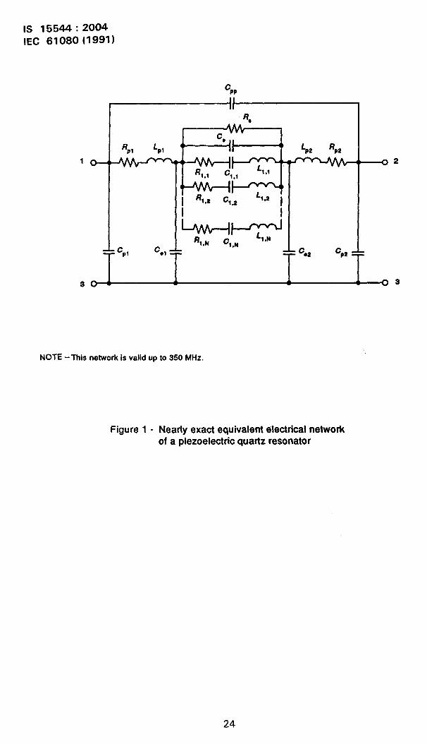
Consisting of a mechanically resonant piezoelectrically excited quattz element togetherwith some means of mechanical mounting within a protective enclosure, a crystal unit canbe exactly represented by an equivalent two-pori network as shown in figure 1. In thisnetwork, CP1 and CP2 represent the electrical capacitance between each connecting pinand the surrounding ground planes (the enclosure itself, if made from a conductingmaterial). CPP represents the capacitance directly between the contacting pins. RPt andR are the equivalent resistances of the mounting structures which support the quartzel%nent, while L and LP2 are the equivalent inductances of these structures. Ce repre-sents the electri%l capacitance between the two electrodes, while Cel and Ce2 are thecapacitances between each electrode and the surrounding ground planes. R* representsconductivity between the electrodes of the resonator, due to a leakage path. In the case ofquartz resonators at moderate frequencies, R~ can usually be neglected (except if thereare defects in the plating masks), but it may be significant for high frequency, high over-tone quartz crystal units.
The series resonant branches represent the equivalent electrical parameters associatedwith each mechanical resonance of the quartz plate. Since quartz plates are of finitedimensions, there will be a large number of resonant modes, many of which can beexcited piezoelectrically, and others which can be excited by mechanical coupling to_othermodes. One of these resonances will correspond to the “design mode” of vibration; theothers will be “spurious” or “unwanted” modes for that application, and will correspond toother overtone modes of thickness shear, width shear, extensional and flexure vibrationsas well as the enharmonic modes of thickness shear and thickness twist.
While this model of a crystal unit is quite complete, and capable of describing its electricalresponse over a very wide frequency range, it is fortunate that this degree of sophis-tication is rarely, if ever, needed. In the remainder of this standard, we will consider threedegrees of simplification from this very general equivalent circuit, and discuss some of theapplications for which each is suitable.
3 Simplified equivalent networks
In most cases, the response of the crystal unit to applied electrical signals needs be consi-dered over only limited frequency ranges, which will include the “design mode” frequencyand may include one or more of the other “unwanted” mocks. The frequency range of inter-est may extend above and below the desired mode frequency by only a fraction of apercent, or in the case of a filter application, a range of several percent may be required.If the application is a filter circuit, or a voltage-controlled or temperature-compensated
1

IS 15544:2004IEC 61080(1991)
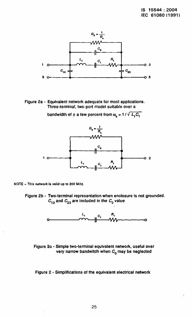
oscillator circuit, more exact modelling of the crystal response over the frequency band ofinterest may be needed. For these applications, the equivalent network of figure 2a is usu-ally suitable. Here, the shunt capacitances between pin and ground and between electrodeand ground are not distinguished.
The residual inductance and resistance of the mounting structure are not separatelydetailed, but are included in the equivalent motional parameters of the crystal unit. Sincethe frequency band of interest is relatively narrow, this will introduce little error. However,it is well for the circuit designer to be aware of the more complex network topology, asoccasional spurious circuit behaviour can sometimes be explained by consideration of theentire equivalent circuit of figure 1. (For example, very high frequency oscillation canoccur due to LPI and L ~ together with the shunt capacitances to ground resulting in somekind of failure of the #esign mode resonance!) While filter applications in particular mayrequire specification of one or more of the “unwanted” modes, it is usually sufficient toascertain that their resonance frequency lies outside a particular narrow band and/or theirequivalent series resistance is greater than some specified value. It will in general benecessary to evaluate the capacitance between pins and ground (C13 and C2J as well asthe total capacitance between pins (Co). Motional resistance (Rl) and motional inductance(Ll) are of prime importance as they determine the band-shape characteristics of the filter,or the frequency tuning characteristics and gain margins of the circuit.
At high frequencies (above about 100 MHz) the effect of the inductance of mounting leadsin combination with the capacitances from pins to case and electrode structure to casetransforms the actual motional parameters of the quartz element, so that the equivalentparameters ,measured at the reference plane (2 mm below the seating plane of the enclo-sure) are somewhat different. The addition of a shunt conductance between pins in theequivalent circuit is usually sufficient to model the effect, as the applications circuit willonly be aware of the effective parameters at the reference plane, and the fact that themotional equivalent parameters seen at this point differ somewhat from those of the quartzelement alone is not significant.
For those cases which require good modelling”of the crystal unit in a filter circuit or in atunable oscillator application, then the parameters which are needed are:
- series resonance frequency, f~;
- motional resistance, /?l;
- motional equivalent inductance, ~1 (or capacitance c1);
- shunt conductance, Go;
- shunt capacitance, Co;
- pin-to-case capacitances, C13 and C23.
In some instances, it will also be required to determine the frequencies and the effectiveresistance of one or more unwanted modes which are located near the design modefrequency.

IS 15544:2004IEC 61080(1991)
For somewhat less exacting applications, such as in simple narrow-band filters where onlythe pass-band shape is critical, or in oscillators which will operate at fixed frequency, theequivalent circuit can be further simplified. As shown in figure 2b a two-terminal equivalentwhich neglects the pin-to-case capacitances may suffice. In this case, however, it is wellto specify whether or not the enclosure will be connected to the same point as one of thecrystal leads, as the value of Co will depend upon how the connections are made. [f theunit is measured with the enclosure ungrounded, the COvalue will include the two pin-to-case capacitances in series; if both the enclosure and one crystal unit lead are to beconnected to the same point in use, the effective Co value will be different.
The parameters needed for the equivalent circuit of figure 2b which will allow reasonablemodelling of the crystal response over a frequency range of a few percent near f~are:
- series resonance frequency, f~;
motional resistance, RI;
- motional inductance, L, (or capacitance, Cl);
effective shunt capacitance, CO.
However, in many oscillator applications, it is sufficient to determine th$ resonancefrequency (at which the transfer phase is zero) together with the insertion resistance atthis frequency; or, if-the oscillator uses a fixed value of load capacitance, the load reso-nance frequency and load resonance resistance at the specified load capacitance are allthat are required. The equivalent circuit for these cases may be represented as in figure2c. The effective motional parameters for the case of resonance operation are essentiallythe same as those of the series branch in figure 2b; however, for the case of operationwith a load capacitor, resistance and inductance as well as frequency are different. As willbe discussed later, measurement of the load parameters poses some special problems.
When figure 2C represents the series resonance condition, it will be found adequate topredict behaviour at frequencies very near resonance, where the impedance of the seriesresonance branch is small compared to the impedance of the shunt capacitance co, @the figure of merit of the crystal unit is greater than about 10:
1M= — >>10
0, Co RI
where
O* is the angular series resonance frequency = 2X f~
COis the shunt capacitance
R, is the motional resistance.
This condition will usually be met by most quartz crystal resonators operating on funda-mental, third or fifth mechanical overtones at frequencies below about 150 MHz.
3
IS 15544:2004IEC 61080(1991)
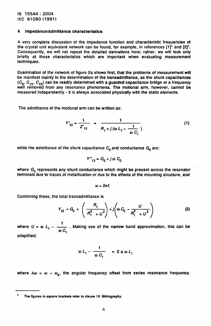
4 Impedance/admittance characteristics
A very compiete discussion of the impedance function and characteristic frequencies ofthe crystai unit equivalent network can be found, for exampie, in references [1]* and [2]*.Consequently, we wiii not repeat the detaiied derivations here; rather, we wiii iook oniybriefiy at those characteristics which are important when evacuating measurementtechniques.
Examination of the network of figure 2a shows first, that the probiems of measurement wiiibe manifest mainiy in the determination of the transadmittance, as the shunt capacitances(Co, C13, C2J can be readily determined with a guarded capacitance bridge at a frequencyweii removed from any resonance phenomena. The rnotionai arm, however, cannot bemeasured independentiy - it is aiways associated physically with the static eiements.
The admittance of the motionai arm can be written as:
Y,*=L . 1
z’, * /?1+j(03L1- --%0) c1
(1)
whiie the admittance of the shunt capacitance Co and conductance GOare:
y,,12 =GO+]OCO
where GO represents any shunt conductance which might be present across the resonatorterminais due to traces of metaliization or due to the effects of the mounting structure, and
6) = 2zt.
Combining these, the totai transadmittance is
“2=G0+(@R:u2)+’fcO~2) (2)
1where U = o f, - — . Making use of the narrow band approximation, this can be
0 c1simplified:
1(o f,- — =2 AUL1
(0 c1
where A@ = o - o~, the anguiar frequency offset from series resonance frequency.
● The figures in square brackets refer to clause 16: Bibliography.
4
IS 15544:2004IEC 61080(1991)
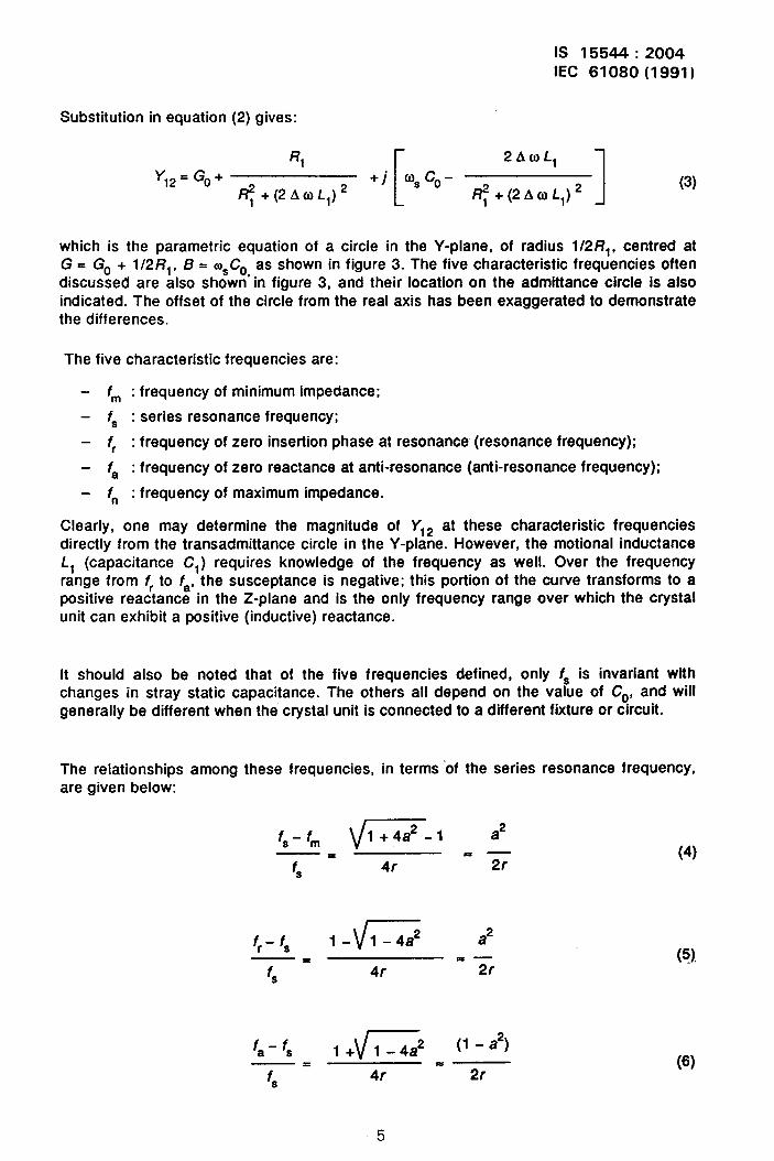
Substitution in equation (2) gives:
RI
[
2Aril L,Y,z = Go+ +j 6)~co-
~+(2A0L1)2 ~+(2A0L1)2 1 (3)
which is the parametric equation of a circle in the Y-plane, of radius l/2R1, centred atG = GO + l/2R1, B = m~COas shown in figure 3. The five characteristic frequencies oftendiscussed are also shown’ in figure 3, and their location on the admittance circle is alsoindicated. The offset of the circle from the real axis has been exaggerated to demonstratethe differences.
The five characteristic frequencies are:
- fm : frequency of minimum impedance;
– f~ : series resonance frequency;
- fr : frequency of zero insertion phase at resonance (resonance frequency);
– fa : frequency of zero reactance at anti-resonance (anti-resonance frequency);
- f“ : frequency of maximum impedance.
Clearly, one may determine the magnitude of Y12 at these characteristic frequenciesdirectly from the transadmittance circle in the Y-plane. However, the motional inductanceL, (capacitance Cl) requires knowledge of the frequency as well. Over the frequencyrange from f~to fa, the susceptance is negative; this portion of the curve transforms to apositive reactance in the Z-plane and is the only frequency range over which the crystalunit can exhibit a positive (inductive) reactance.
It should also be noted that of the five frequencies defined, only f~ is invariant withchanges in stray static capacitance. The others all depend on the value of Co, and willgenerally be different when the crystal unit is connected to a different fixture or circuit.
The relationshipsare given below:
among these frequencies, in terms of the series resonance frequency,
f~- fm v*-1l+4a a2
—=f, 4r ‘z
(4)
vfr-f~ 1- l-4a2 a2—=
f~ 4r = Tr
fa- f~P “ -a*)1+ 1-4a—=
f~ 4r “T
(s),
(6)
5

IS 15544:2004IEC 61080(1991)
f“ - f~ r (“a’)1+ l+4a—=
f~ 4r = 2r(7)
where
Co RI r coa. ad r. —
m~L,C, ‘T c1
We see that the frequency of minimum impedance is slightly less than f~, and the reso-nance frequency of zero phase is greater than f~, the differences being a function of thequality factor Q and the ratio of capacitances (Co/C1). To illustrate the magnitudes,assume first a fundamental crystal unit of good quality, with r = 200, Q = 400 000. Theseparation between fmand f~, and between fr and f~will be less than 1 x 10⁻⁹. However,for an overtone crystal with r = 5 000 and Q = 30 000 the separation will be about28 x 10-6 Whether or not these frequency definitions may be used interchangeably willciearly depend upon the tolerances required, and the parameters of the crystal unit. (Thehigh impedance frequencies fa and fn are rarely specified, as they depend strongly on theshunt capacitance, and therefore will usually be much different when connected into auser circuit than when placed in a test fixture.)
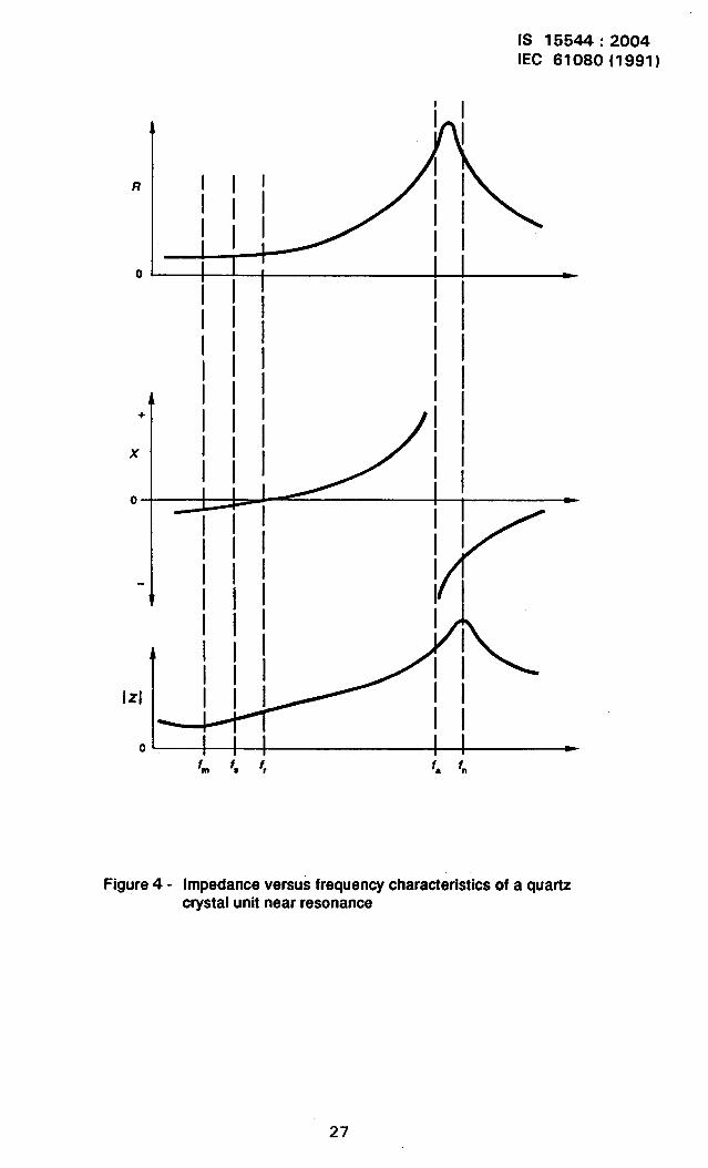
Figure 4 is a symbolic plot of the magnitudes of the real and imaginary components ofcrystal transimpedance, Z ,2, again indicating the characteristic frequency points definedabove.
Information about the value of the motional inductance/capacitance is contained in therelationships of figure 4. While the locus of the admittance-plane circle depends only onthe magnitude of /?l and the ratio of COto Cl, the separation between the characteristicfrequencies and the slope and magnitude of the reactance/impedance functions dependon the value of f, as well. We have already seen (equations (4), (5) and (6)) that:
f~-fm fr-f~ a’ fa-f~ l-a’and —.—
~= f~ -z f~ 2r
It can also be shown ([1] and [2]) that the crystal unit connected in series with a loadcapacitance CL will have a composite resonance frequency fLsuch that
fL- f~ c1—=
f~ 2(C0+ CL)
provided any stray capacitances are either neglected or included in Co.
(8)
The equivalent circuits of figures 2a and 2b have exactly the same transadmittance charac-teristics; they differ only in the definition of values for the “stray” static capacitance values.
6

IS 15544:2004IEC 61080(1991)
The circuit of figure 2c, however, does not take into account the presence of any shuntcapacitance, and therefore will only serve to approximate the impedance of the deviceover a small frequency range near series resonance. Over this range
1z12=R1+j((oL1- —)=/?1+j(2Aa)~1)
cl)c,(9)
which is exactly the same result one obtains if it is assumed that
12A QLl <<—
(i)~co
in equation (3) above. in this case, the crystal reactance is:
xc=2Aa L1 =4n L1(f-f~).
Differentiating,dXC
4 n L, (Q/Hz), or7=
1 dXCL1=—. —
4X df(10)
and L, may be directly determined from the slope of the reactance versus frequency func-tion evaluated in the neighbourhood of f~.
5 Parameters to be measured
Characterization of a crystal unit, therefore, requires determination of series resonancefrequency, f~; the motional resistance, R,; the motional inductance, L1 (or capacitanceCl); and the three static capacitances, C13, C23 and Co. Other characteristics which areoften specified are the derived characteristics:
fL: load resonance frequency; the frequency at which the series connected combina-tion of crystal unit and a specified value of load capacitance will exhibit a resonant,zero phase condition;
- FfL-load resonance resistance; the real component of crystal unit equivalent imped-ance at frequency fL;
- S-pulling sensitivity; the rate of change of fL with changing load capacitance at aload capacitance CL;
- AfL1,Lz pulling range; the difference between two load resonance frequenciescorresponding to two specified values of load capacitance.
These characteristics are termed “derived” because they may all be calculated fromthe values of the shunt and motional parameters and the value of f~. With suitable
7
IS 15544:2004IEC 61080(1991)
instrumentation they may also be measured with or without the introduction of physicalcapacitors into the measuring fixtures, as will be described below.
It is common practice to specify the resonance frequency fr (frequency of zero phase)instead of series resonance frequency f~. Generally, the difference between the two isnegligible for fundamental mode units; however, when dealing with fifth and seventh over-tone units, fr - f~can be as great as several parts per million, and differentiation is neces-sary. f~ is the preferred parameter, as it is independent of stray capacitance effects. It isalso necessary to be very specific about the definition of the “zero phase” condition: fr isprecisely defined as that frequency for which the transadmittance vector Yt2 is purelyconductive. This is not identical to the frequency at which the transmission in a test fixtureexhibits zero phase shift, as the transmission phase shift depends upon the physicallength of path between the test pins, and on the nature of the terminating impedances ofthe test pins. Again, the difference is small at lower frequencies, but can become signi-ficant for frequencies of 100 MHz or greater. At 100 MHz, for example, a matched linelength of one centimetre results in a phase delay, A@ Of about 0,02 radians; a resonatorhaving Q = 10000 would exhibit a frequency error of
Af A@—s —= lX IO-6
f. 2Q
if the terminations are truly resistive. Consequently, great care is required in establishingthe reference conditions when calibrating and adjusting real test fixtures and instruments.
6 Attributes of measurement systems
While a number of techniques have been described, and may be used, to obtain some orall of the network parameters described above, it seems appropriate to discuss first thegeneral requirements for determination of the equivalent network parameters.
As noted above, one must determine both magnitude and phase of the admittance (orimpedance) of the device at various frequencies in order to solve for the network para-meters. Consequently, the measurement equipment shall permit calibration in terms ofrecognized standards of impedance and phase, and shall be equipped with means forfrequency measurement. Today, many calibrated frequencies are broadcast, and it is arelatively simple matter to maintain a laboratory frequency source within 1 x 10⁻⁹ or betteragreement with national standards.
Standards of phase and impedance, however, especially at frequencies above 100 MHz,are not easy to achieve, and generally can only be obtained in coaxial form, at imped-ances of 50 Q or 75 Q. Such standard impedances with traceable calibration to anaccuracy of better than 1 9’0, and matched air lines with accurately known characteristicimpedance and effective length (phase standards) calibrated to better than *1 mm can bereadily obtained. Short-circuit and open-circuit conditions can be established from firstprinciples.
8

IS 15544:2004IEC 61080(1991)
Reference impedance standards for use in fixtures based on other than 50 f2 or 75 Q arenot readily obtained, and require considerable effort to produce and calibrate.
Similarly, considerable ingenuity is always required to connect known impedances intotest fixtures designed. to accept the wire leads of crystal units without at the same timeintroducing additional stray reactance and extra line length.
With these general precautions in mind, we will examine some of the possible techniquesfor crystal measurement.
7 Active methods (oscillator or other closed-loop methods)
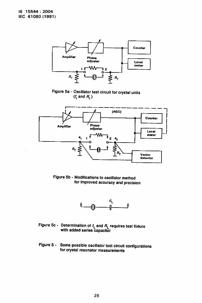
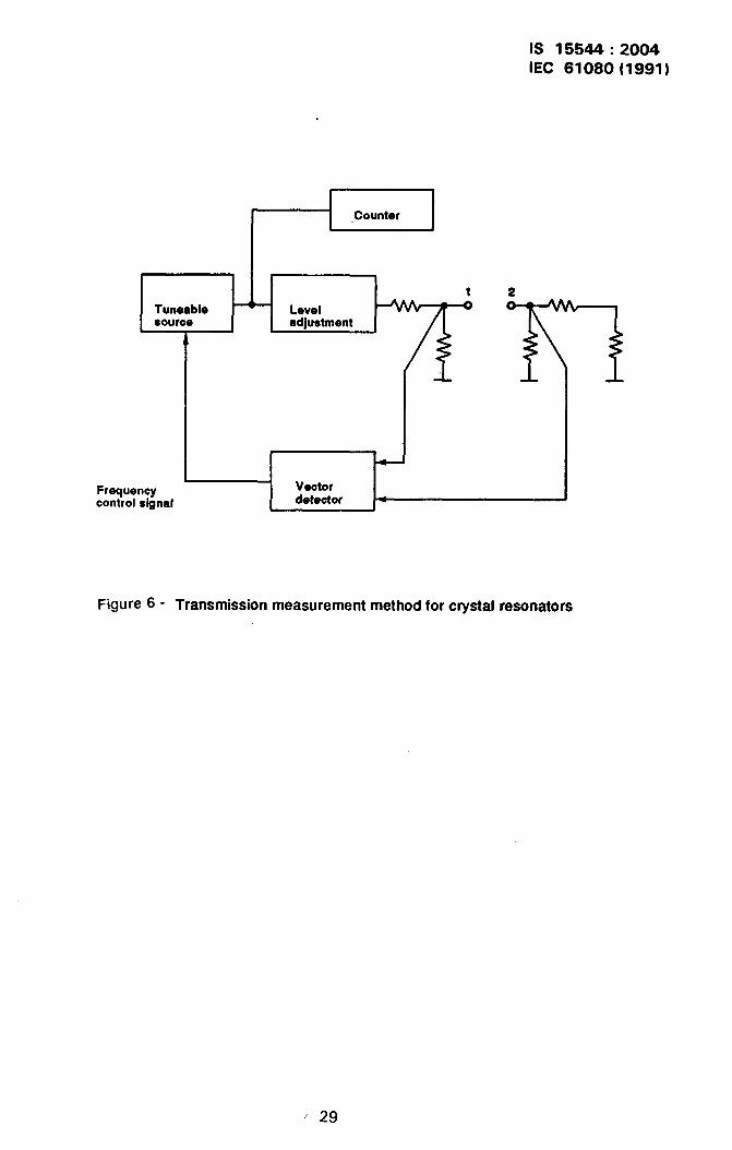
In principle, it is possible to construct a broad-band (or tuneable) active circuit which willsustain oscillations when a feedback loop is closed by inserting a crystal unit. The condi-tions for oscillation are well known: the net loop phase shift shall be 2mc, n = O, 1, 2 ... andat equilibrium, net loop gain is unity. Such a circuit is shown in figure 5a, where a crystalunit or other impedance element completes the positive feedback loop by connecting be-tween points 1 and 2. If the voltages at these pins, e, and ez, have precisely the samephase, then a crystal unit connected in the circuit will control the frequency of oscillation atits resonance frequency, fr. The oscillator sustaining circuit may be replaced by a tunablesource and a phase detector as shown in figure 6 (where an automatic tracking arrange-ment is shown, but manual tuning may also be used) with the same result, i.e., the zero-phase frequency is determined. If the impedances presented by the test circuit atterminals 1 and 2 are accurately known, we can calculate the resonance resistance /?r ofthe device from knowledge of the amplitudes of et and e2, for example, using a vectorvoltmeter as in figure 5b. In this circuit, the frequency would be adjusted to give exactlyzero phase between e, and ez, and the resonance resistance found from the ratio of themagnitudes:
% Rr + RTRr =
()
%—. —-1 RTf32 RT ; :2
(11)
where RT is the effective terminating resistance from test points to ground, while the valueof fr could be determined by measurement of the source frequency when the zero phasecondition is satisfied.
If, however, there is any stray reactance appearing in shunt with the terminating imped-ances at points 1 and 2, both the frequency and the resistance determined above will be inerror. The accuracy of this type of measurement depends upon the accuracy of the meterand the precision with which the circuit impedances can be realized. Repeatability of sucha system will in general be quite good, so long as the same instruments and test fixturesare used, but the accuracy achieved (due to unavoidable stray reactance) will depenqalso on the motional parameters of the crystal unit being measured.
At this point, it should be noted that very little data are available to allow comparison ofmeasurements between different measuring methods. Most “round robin” experimentshave been restricted to comparison of results using equipments of the same kind atdifferent locations.
9

IS 15544:2004
IEC 61080(1991)
Measurement of motional inductance/capacitance using the oscillator or transmissionmethods described above can in principle be accomplished in either of two ways. Onemethod calls for the introduction of “known” values of capacitance in series with thecrystal unit, and determining the change in frequency which results, as indicated by the.connection of figure 5c, using equation (12) below. Adjusting frequency to the zero-phasepoint gives the load resonance frequency, fL, and the load resonance resistance, RL,directly. With this connection, it is very important that any stray capacitance to groundfrom the interconnection point between crystal unit and loadknown, and included in the effective value Of CL.
Because of the difficulty of determining these strays accurately,
capacitor be accurately
it is often easier to usetwo different values of CL, using test-capacitor fixtures as nearly identical as possible sothat all strays are essentially the same with each fixture. Then, the motional inductance isdetermined from equation (13) below:
The calculation of L, (or Cl) using a single load capacitance CL is:
1 2 (f - f~) (co+ CL)=C1=
Q):L, f~(12)
Using two load capacitances CL, and CL2,
1 2 (f~l - f~) (f~z - ‘~) ( CL2 - CL1)=C1= (13)
# L, ‘~ (fLl - ‘L2)
In the case of two load capacitances (equation (13)), the value of Co is not required andonly the difference between the load capacitance values is needed. Strays introduced bythe test capacitor fixtures do not influence the result, so long as they are the same for thetwo fixtures.
The second method for determining motional parameters requires that, after the values offr = f~ and R - RI have been determined using the circuit configuration of figure 5b, thephase adjusfer setting is changed to produce two phase conditions between e, and e2 voit-ages of opposite sign and equal magnitude, *AO and the frequencies required for eachphase condition are measured (f, and f2). Knowing the test circuit impedances RT, themotional resistance of the crystal unit RI and the series resonance frequency f~, themotional capacitance Cl (or inductance L,) is calculated:
1 (f.2- Q cot(A 4)c1= —= — (14)
m: L, f: 2 (2%+ RI)
10
IS 15544:2004IEC 61080(1991)
This technique has the advantage that no additional stray reactance are introduced inmaking the measurement. However, especially when operated manually, the accuracy ofthe value determined depends directly on the accuracy with which RT and R, are knownand the accuracy of the phase shift value introduced. The motional parameters cannot bedetermined with any better accuracy than the network and crystal resistances known.Also, some additional error will be introduced due to the effects of the shunt capacitanceCo, which has been neglected in obtaining equation (14).
Probable accuracies obtainable with the above oscillator/transmission methods are consi-dered to be about *1 x 10“6 for fr, *5 % for Rr and *8 Y. for L, and Cl, if reasonable carein calibration of the vector detector and in the fabrication of the test fixtures is exercised.At higher frequencies (above about 100 MHz), accuracy is degraded as unavoidable strayreactance become more significant. When measuring high order overtone crystals(seventh, ninth, etc.) it is not unusual to find that no zero-phase condition is possible.
All of the above oscillator and transmission methods can be operated without phase detec-tion, but at reduced accuracy. When the oscillator method is used, an inherent phasecondition is established, but unless a vector detector is used, the actual value of loopphase shall be suspect and the accuracy of the measurement is not well established. How-ever, oscillator measurements can be very repeatable when the same equipment is used,making them very useful for use in manufacturing situations, as long as better means areused to assure the required accuracy and correlation with respect to standard methods ofmeasurement.
Externally excited transmission circuits, when used without phase detection, determine thefrequency of minimum impedance, fm, rather than the resonance frequency, fr. Since fmlies below f~ by about the same amount that fr lies above it, the accuracy is nearly thesame; and in either case, it is well to keep in mind just what is being measured. However,when operated manually, it is more difficult to estimate the point of maximum transmissionthan to set the point of zero phase - this is not a consideration when computer-automatedequipment is used, as curve fitting to measured points will allow very accurate inter-polation to the precise frequency of the maximum.
Transmission test fixtures may be of the n-network type as described in IEC Publication444, or of the T-network type as described in [12] and [13], as well as of other designs. Inany case, the design and fabrication of the test fixtures are of critical importance, andcorrelation of results requires that all fixtures used shall be exactly alike.
8 Bridge methods
R.F. impedance and admittance bridges have been used for the measurement of crystalunit equivalent parameters in the vicinity of resonance [4]. Such bridges depend upon thecalibration of the internal elements used in setting balance conditions, and are not easilystandardized to available coaxial impedance standards especially at higher frequencies.Moreover, their use generally requires considerable care in adjustment, so that they arenot well-suited for production measurements. Because of the limited reactance range ofmost commercially available bridges, load frequency and resistance measurementsusually require the use of physical test capacitors placed in series with the device undertest.
11
IS 15544:2004IEC 61080(1991)
An automated microcircuit realization of a Scheering bridge [5] has been developed as anautomatic crystal parameter measurement system. The details of this automatic systemare beyond the scope of this guide. In general terms, it is based on a miniaturized bridgewhose tuneable elements are varactor diodes, enabling electronic balancing of the bridgeunder control of a computer system. The details of this development have been published[7] and reported accuracies are very good.
An automatic measurement method based on a commercially available reflection coeffi-cient bridge (impedance meter) has also been developed and reported [6]. This equipmenthas a coaxial measurement port, and is calibrated using standard 7 mm coaxial impe-dance elements, which can be readily obtained and easily certified by most nationalstandards laboratories. Adaptors must be provided to permit connection of the wire leadsof crystal units to the coaxial port, and their characteristics shall be accounted for whenconverting measured reflection coefficients to equivalent crystal parameters. Reportedaccuracy obtainable by this method is very good [6], [8]. Load resonance frequency andresistance can be determined by the phase offset method as described by Smythe [6], sothat physical capacitor fixtures are not required - a significant advantage.
Since the reflection coefficient bridge is a single port system, one terminal of the crystalunit under test must be grounded, and it is not therefore possible to determine Co, Cl ~ andC23 separately with this system. They may be found from measurements made away fromresonance with the enclosure grounded and ungrounded and lead connections reversed, ifnecessary.
For frequencies below the range of the reflection coefficient bridge (impedance meter),low frequency network analyzers are commercially available, having frequency capabilityfrom about 50 Hz to slightly above 10 MHz. These instruments measure the transmissioncharacteristics of devices as two-port networks and calculate the equivalent series orparallel form of the trans-immittance parameters. They also permit determination of crystalload parameters by the phase offset method.
9 Automated network analyzer methods
Automatic two-port network analyzers have been developed for the general characteriza-tion of active and passive networks. These analyzers provide for the determination of thetwo-port scattering parameters of the network under test, and provide for correction of themeasured responses to take into account imperfections in the equipment by referringnetwork parameters to the impedance standards used to calibrate the equipment. Acomplete description of this type of equipment may be found in [9]. Commercial networkanalyzer/S-parameter instruments of this type are now available. For use as crystalmeasurement ‘systems, stable synthesized signal sources shall be included in the system;some systems include such sources while others need to be modified for this use. Suchsystems provide for calibration at the measurement reference plane with coaxialimpedance standards, and are capable of very accurate and reproducible measurements[1O], [11]. The use of the scattering parameter methods, originally developed for applica-tion to microwave systems, allows for the separation of the trans-immittance parametersfrom the effects of shunt elements, so that the static capacitances C13 and C28 may beseparated from the transmission characteristics and determined separately.’ Also, the test
12’
IS 15544:2004IEC 61080(1991)
fixture imperfections are to at least to a first approximation removed from the measure-ment, as the “calibration” of the system is done at the measurement ports, and the errorcorrection algorithms remove the effects of the system up to the reference plane from themeasurements.
These automatic network analyzer systems have proved to be the most satisfactory way ofobtaining precise measurements of immittance over very wide frequency ranges. Eitherone-port reflection measurements or two-porl transmission measurements may be madeas desired. For crystal unit measurements, the choice of one-port or two-porl measure-ment is generally arbitraty, as the two yield essentially identical values for the motionalparameters, differing only in the values of the static capacitances. As a guide, the follow-ing are general recommendations:
One-port measurements -
Two-porl measurements -
Low resistance crystal units (Rl < 10 Q); crystal units foroscillator applications; situations where minimum measure-ment time is important.
High resistance crystal units (Ffl >100 f2); crystal units forfilter use and some exacting oscillator applications; highfrequency crystal units (f~ >100 MHz).
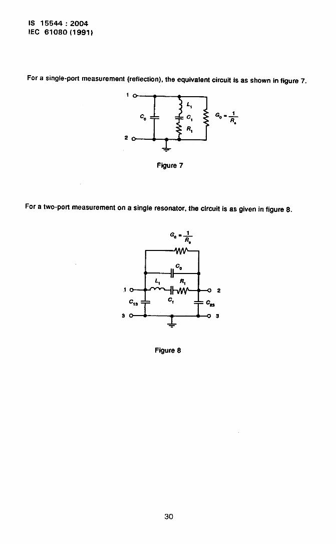
Figure 7 shows the equivalent circuit of a crystal unit as connected for a one-porl measure-ment and figure 8 shows the equivalent circuit of a crystal unit connected as a two-pofldevice. The shunt capacitance Co of figure 7 includes the capacitances Cl and Cz offigure 8 in some combination (depending upon whether the enclosure is grounded or not)and thus differs from COof figure 8.
The measured reflection response obtained for a one-port measurement is typified byfigure 9, while figure 10 is a typical transmission response for a crystal unit in a two-podconfiguration.
A functional block diagram of the equipment required for the network analyzer method ofmeasurement is shown in figure 11. The entire measurement and data reductionprocesses are controlled by computer programmed, so that operation is extremely simple,and measurement accuracy is essentially independent of operator skill.
10 (commercially available measurement systems
The instrument systems just described can all be used for the measurement of piezo-electric resonator parameters; however, many require some modifications such asimproved signal sources, the addition of frequency counters or special detectors, etc.There are also available various measurement systems designed specifically for resonatormeasurement. These range from the manually operated “crystal impedance meter” testoscillators to special automated transmission measurement systems available fromseveral manufacturers. Some of these are based on transmission networks electricallyequivalent to that specified by IEC Publication 444, and use sophisticated computer-controlled synthesizers and vector detectors. Some such systems also include auto-
13
IS 15544:2004IEC 61080(1991)
matically controlled temperature chambers and switching networks to permit temperaturetesting of large numbers of units in batch mode.
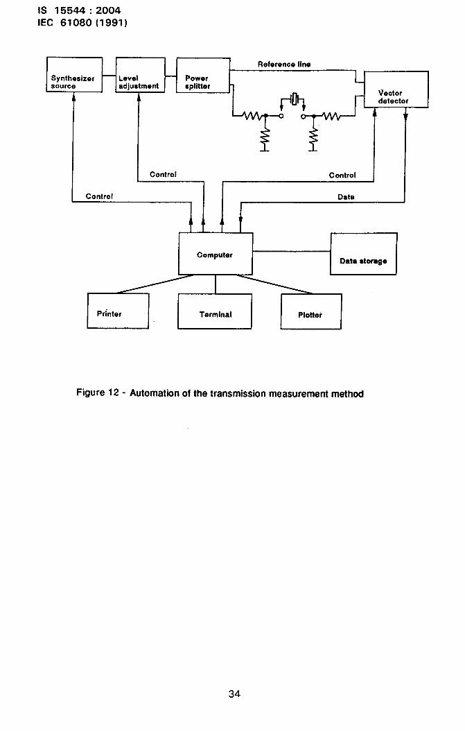
The automated transmission test systems, shown in block diagram form in figure 12, withthe capability of extensive mathematical data processing along with storage of measuredtransmission parameters during calibration with known impedances, provide betteraccuracy and repeatability than manually operated systems. These systems depend onthe measurement of the output voltage of the test network, compared to the voltage of areference channel. Considerable care is taken to isolate the reference channel from thetest channel; however, the insertion impedance of the test device can only be obtainedwith respect to the assumed impedance of the reference resistors which are used tocalibrate the system. These resistors are not coaxial devices and cannot be easily tracedto national standards of impedance at high frequencies. Also, since the transmissionparameters will be influenced by any shunt impedance between pins and ground, whichcannot be separated without making other measurements, the accuracy of the derivedparameters will be degraded, especially at higher frequencies. The use of several valuesof reference resistors permits modelling of the test fixture impedances, which reduces therequirement for fixture precision, and improves the precision of measurement over thatwhich can be obtained with manual measurement systems or with oscillator methods.
Software and test fixtures specially designed for use with automatic networkanalyzer/scattering parameter systems are becoming commercially available. These soft-ware programmed are developed to operate with specific instruments and controllers andin some cases are available from the instrument manufacturers, while other programmedare furnished by third-party vendors. This availability has significantly reduced the cost offully automated network analyzer systems for crystal unit measurements.
11 Comparison of the characteristics of various measurement systems
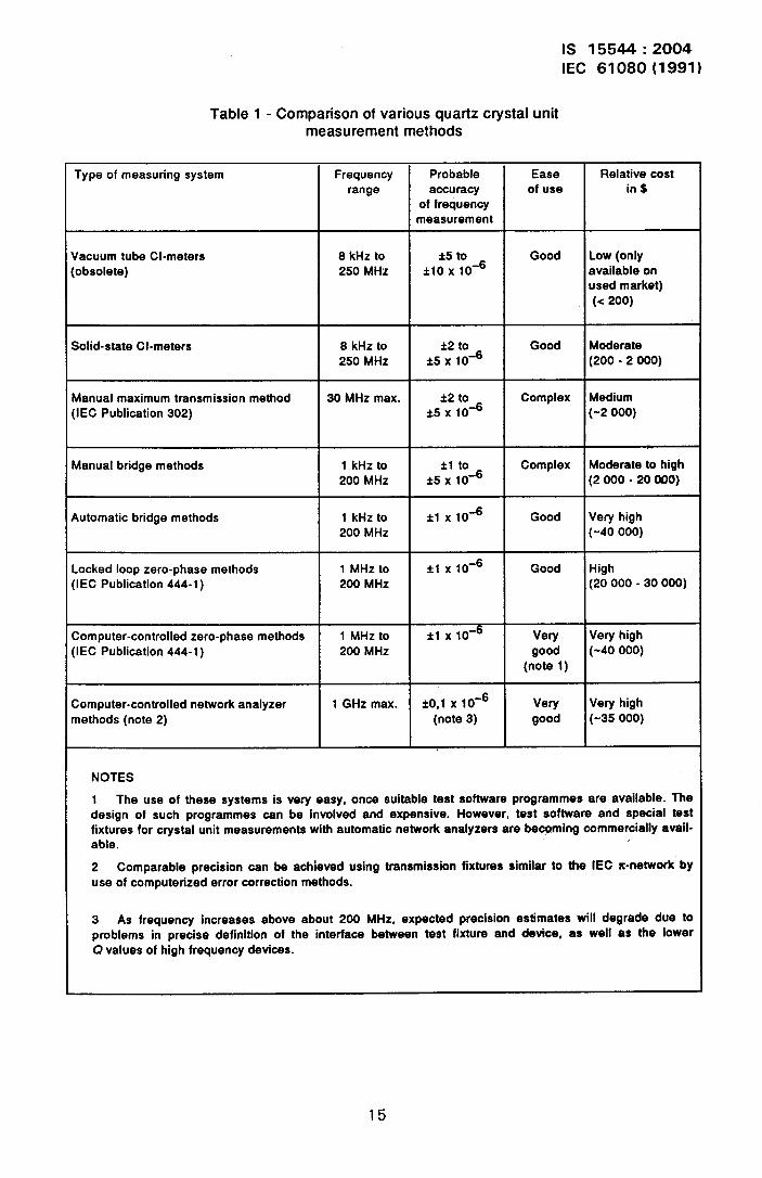
The various measurement systems described have some characteristics which are gener-ally determined by the basic method employed. The following table gives a relativecomparison of the basic methods with regard to these general characteristics.
14
- --
IS 15544:2004IEC 61080(1991)
Table 1- Comparison of various quartz crystal unitmeasurement methods
Type of measuring system Frequency Probable Ease Relative costrange accuracy of use in $
of frequencymeasurement
Vacuum tube Cl-meters 8 kHz to *5 to Good Low (only[obsolete) 250 MHz *IO x 10-6 available on
used market)(< 200)
Solid-state Cl-meters 8 kHz to *2 to Good Moderate250 MHz *5 x 10-6 (200 -2 000)
Manual maximum transmission method 30 MHz max. &2 to Complex Medium(IEC Publication 302) is x 1o-= (-2 000)
Manual bridge methods 1 kHz to *1 to Complex Moderate to high200 MHz *5 x 10-6 (2 000-20 000)
Automatic bridge methods 1 kHz to *1 x 10⁻⁶ Good Very high200 MHz (-40 000)
Locked loop zero-phase methods 1 MHz to *1 x 10⁻⁶ Good High(IEC Publication 444-1) 200 MHz (20 000-30 000)
Computer-controlled zero-phase methods 1 MHz to *1 x 10⁻⁶ Very Veryhigh(IEC Publication 444-1) 200 MHz good (-40 000)
(note 1)
Computer-controlled network analyzer 1 GHz max. *o,1 x 10-6 Very Very highmethods (note 2) (note 3) good (-35 000)
NOTES
1 The use of these systems is very easy, once suitable test software profyammes are available. Thedesign of such programmed can be involved and expensive. However, test software and special testfixtures for crystal unit measurements with automatic network analyzers are be+ming commercially avail-able. ,
2 Comparable precision can be achieved using transmission fixtures similar to the IEC x-network byuse of computerized error correction methods.
3 As frequency increases above about 200 MHz, expected precision estimates will degrade due toproblems in precise definition of the interface between test fixture and devfce, as well as the lowerQ values of high frequency devices.
15

IS 15544:2004IEC 61080(1991)
12 Parameter determination with automated S-parameter systems
The automatic network analyzer systems described obtain the scattering parameters of thedevice under test, fully corrected for system error terms. From these S-parameters, theadmittance parameters of the device are calculated using standard transformations. Themeasurements are made at several frequencies around series resonance of the unit, sothat an array of measurement frequencies and corresponding Y12-data is obtained, fromwhich the equivalent electrical parameters may be estimated. One method of estimation isby means of an iterative non-linear least squares method [11] which directly calculates the“best fit” values for /?1, f.,, Cl and Co. If C13 and C2a are also required, the Y,, and Y12admittance parameters are also needed from the measurement, There are several differ-ent approaches for non-linear least squares estimation, including the variable metricmethod [11], which converges rapidly but requires calculation of both first and secondderivatives at each frequency; the Gauss-Newton method, which converges much moreslowly; and the Marquardt method of steepest descent, which uses first derivative informa-tion only. For any of these iterative methods, it is necessary to obtain good initialestimates of the parameters if reliable and rapid convergence is to be assured. Initialestimates can be obtained with one of the linear methods below. Depending on the needfor precision, and the importance of rapid measurement, the linear methods may provideadequate results without further processing.
If only the motional parameters are needed (Rl, L, and Q, these may be obtained fromthe real component of Y,z (i.e. G12) in the following manner [10]. The expression for G,zis from equation (3):
RIG=
‘2 *+[47c(f - f,) LJ 2
The reciprocal of this expression then is:
(15)
which
a)
b)
c)
has the following properties:
a minimum value of /?1at f= f~;
dE/df is zero at f= fs;
when f~and l?, are known, L, can be determined from the coefficient of the (f- $)2term.
Consequently if the reciprocals of the G12 values are calculated and fitted to a quadraticfunction of frequency, fs is found directly as the value of f for which the first derivative ofthe function is zero. Evaluating the function at this value of f then gives the value of RIdirectly:
16
IS 15544:2004IEC 61080(1991)
E = K, + fK2+ f2K3 (16)
Series resonance frequency is:
K2f~. -—
2K3
Substituting this vaiue for f in the expression for E above, n, is:
K;
R1=K1-—4K3
Itshould be noted that in the presence of a shunt conductance term Go the value of R, wiilbe in error.
Equating the coefficients of the f2 terms in equations (15) and (16) above, the vaiue of L,may be calculated as:
L, = :G
and Cl may be calculated from the defining equation
1c,. —
Lt w:
Since Co is not containedobtained from this analysis.
in the theoretical expression for G12,no estimate of Co is
The advantage of this method of estimating the motional parameters is that it is very fast,requiring few calculations. it has the disadvantages that accuracy is degraded if pointslying further than about one Q-bandwidth from series resonance are inciuded in the caicu-iation, and it is quite susceptible to error in the presence of random noise in the measureddata. A much more robust iinear method makes use of both real arid imaginary compo-nents of the transadmittance data. This method makes use of a linear least squarestechnique to fit a circle in the Y-plane to the measured Y12-points, and then uses themeasured data to obtain the reactance as a function of frequency to allow estimation ofseries resonance frequency and inductance, as described below.
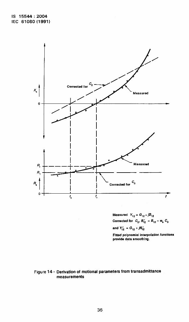
The derivation of motional parameters from two-port measurements is illustrated in figure14. First, the corrected transadmittance values
Y12 = G12+J912
17

IS 15544:2004IEC 61080(1991)
are calculated at each frequency of measurement, and the transimpedance vectors arecalculated as:
G Bz
1212 =
g2 :::2 - i= Rs + jXS
G;2 + Bf2
The values of Rs and X* are plotted in figure 14, and the solid curves represent least-squares fitted polynomial functions fitted to the data points. (To avoid computationaldifficulties, the frequency co-ordinates are transformed by subtracting a constant vaiueapproximately equai to the resonance frequency.) Resonance frequency, $ is then deter-mined at the intercept of the smoothed X. function on the zero reactance axis. Theresonance resistance: Rr, is the vaiue of tk’efrequency co-ordinate.
To obtain vaiues of f~, L, and RI a circie invaiues; this circie wiii be centred at the point
i
smoothed Rs function at this vaiue of the
the Y-piane is fitted to the measured Y12
Gc= Go+- Bc = OSCO2R, ‘
The measured data points are then transited aiong radii to iie on the fitted circie tosmooth the data effectively. (This is a tacit assumption that random errors in each meas-ured component are equaiiy probable.) Then, using the “smoothed” vaiues (after beingtransited to iie on the fitted circie) B. is subtracted from each susceptance component,thus mathematically removing COeffects from the data.
After removing COeffects, the new admittance vectors wiii represent oniy the motionai armparameters. Transformation to the Z-piane resuits now in a constant reai component Rs =RI. The X~ component wiii now be essentially a straight iine over a relatively widefrequency range, intercepting the zero reactance axis at f~,and having a siope
dXJdf= 4xL1
with the accuracy of the narrow band approximation.
These calculations are performed mathematically by the computer, but the graphical repre-sentation illustrates the method.
The ioad parameters, fL and RL, can be calculated from the motbnai parameters and thevaiue of CO;however, for smali vaiues of CL particuiariy, the accuracy of this extrapoiaonmay not be adequate. With the network anaiyzer, additional measurements can be madein the frequency range at which the insertion reactance of the crystai unit is approximatelyequai to the magnitude of the ioad capacitor reactance, and the ioad parameters can thenbe interpolated quite accurately. To accomplish this without the use of a speciai testfixture, the approximate ioad resonance frequency is calculated using the f~, Cl and Coparameters already determined. Then, measurements are made at severai frequencies
18

IS 15544:2004IEC 61080(1991)
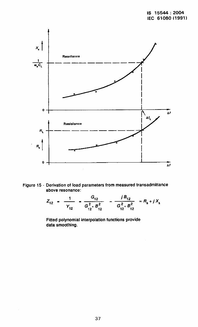
near this value, and the Z12-vectors calculated at each frequency. The resistive andreactive components are then fitted to polynomial functions of frequency as before, asshown graphically in figure 15. The “smoothed” reactance function is used to interpolatethe precise value of t for which X., is precisely equal to the magnitude of the reactance ofthe specified load capacitor, giving an accurate value of fL. The R~ function is thenevaluated at this value of f to obtain an accurate measure of RL.
The smoothed X* function may then be used to calculate several paired values of loadfrequency and load capacitance over a range of *1 O % of the specified CL value. Fromthese, a polynomial function relating frequency to toad capacitance can be formed by aleast squares method,
fL= /$ + K2CL+ K3&L+ K4&L
and the pulling sensitivity, S, calculated as the derivative of this function
S= dfLldCL= K2 + 2K3CL + 3Kh@L
and may be evaluated for the specified load capacitance, as well as for other values withinthe data range. (Extrapolation beyond the range for which data were obtained is alwaysdangerous!).
It must be kept in mind that load resonance parameters cannot be isolated from the influ-ence of Co, including any stray capacitances introduced by wiring paths, etc. These strayswill include the Cl ~ and C23 values of the crystal unit as well as any strays from the circuitbeing used. It is the responsibility of the circuit designer to establish the total effective CLvalue for his amtication. It is often useful. for this reason to obtain the f,, /?, and S loadparameters at ~everal CL values, such as ~0,5 pF, M,0 pF and *1,5 pF ~ffe~ent from thespecified value.
All of these parameters may also be determined from one-port measurementsbearing in mind that the Co-parameter is different with the one-port connection.
as well,
13 Precautions for making precise measurements
When the best possible estimation of the equivalent circuit parameters is desired, specialattention shall be given to avoiding environmental effects which can have a ve?y s“@ni-ficant influence on the results. These include the temperature, temperature gradients,drive level, and characteristics of the test fixture, as discussed below.
13.1 Thermal effects
The frequency, resistance and motional impedance of a crystal unit all depend to somedegree on the temperature and the rate of change of temperature of the unit during themeasurement. In addition, since parameters are estimated from a series of measurementsat several frequencies near resonance, it is especially important that the unit should notbe disturbed during the process of obtaining these measurements as any drift would
19
IS 15544:2004IEC 61080(1991)
distort the best-fit estimation function. [n addition, if close correlation of results obtained atdifferent times is desired, it is important that the measurements be made at precisely thesame temperature or that the temperature coefficients of the parameters be accuratelyknown so that all measurements can be corrected to a common temperature value.
Minimizing thermal gradient effects requires that all the units to be tested, the test fixturesand the instruments be allowed to reach equilibrium with the environment of the test roombefore attempting to make measurements. In addition, crystal units should be handled withplastic tweezers or other non-conducting means to avoid heating by finger contact. Protec-tion from air currents, heat sources and small fluctuations in room temperature can beprovided by placing a relatively massive shield over the unit when it is installed in the testfixture. The temperature of the unit during test can be determined by monitoring thetemperature of this shield with a precision thermometer if sufficient time has been allowedfor equilibrium to be reached. An accurac of better than 0,1 “C is required if frequency
2correlation to within better than 0,05x 10- is needed, as it is not unusual for a crystal unitto exhibit frequency changes as great as 0,5 x 10- per degree.
Because of this sensitivity, special crystal units having very low temperature coefficientsof frequency near room temperature are advisable for correlating measurement equipmentin the factory.
13.2 Drive level effects
It has been widely observed and reported that the parameters of quartz crystal units, espe-cially frequency and resistance, depend on the level of excitation. The effects areapproximately proportional to the square of the drive current, so that precision measure-ments should ideally be made at low drive levels. For thickness shear modes, a testcurrent of no more than about 200 PA or 300 PA r.m.s. is usually satisfactory, while !ow-frequency flexure types may require levels as low as 10 vA. Also, if measurement resultsare to be repeated @ different times, it is necessary that all measurements be performedat essentially the same drive level.
13.3 Test fixture conskleratlons
Most crystal units are equipped with either radial lead wires extendirlg from one surface ofthe enclosure, or with metallic pads on one surface for “surface mounting” to theequipment. Unfortunately, neither of these configurations is compatible with the coaxialconnectors usually found on r.f. test equipment so that some kind of adapting test fixtureis needed. The crystal unit measurements can be no more accurate than the characteriza-tion of the test fixture itself. If an automatic network analyzer method is used, the fixtureup to the reference plane will be included in the calibration of the equipment, and the mainrequirement is that the system as calibrated remains unchanged during the measurement.
One point to consider especiallytance and inductance that mightand the test fixture due to excess
for high frequency measurements is the added capaci-be introduced at the connection between crystal leadslead length of the crystal unit. To eliminate this problem,
20
IS 15544:2004IEC 61080(1991)
the test fixture connector should be a hollow conductor so that any excess lead wire canextend within the connector pin. Also it should be possible to calibrate the system withknown impedances which do not disturb the character of the reference plane. If the meas-urement is to be “traceable” to national standards, the reference impedances shall be certi-fied from first principles, such as short or open circuits, or they shall be equipped withcoaxial connections or other adapters which are certified by a standards laborato~. Testfixtures and calibration standards which meet these requirements are now commerciallyavailable.
13.4 Transients in the measuring system
When measuring crystal units it should be recognized that transient behaviour will occur,when excitation frequency is changed in both the instrumentation (such as the settlingtime for a synthesizer after a frequency is programmed or the time required for a switchclosure to become stable or the time required for a detector to reach a stable indication),and in the device itself. The latter may well be the longer time, particularly for lowfrequency or high Q devices.
The behaviour of the crystal unit response immediately after a step change in excitationfrequency has been made can be explained as consisting of two simultaneous transients.First, the initial frequency signal will decay with a time constant proportional to the ratioC?/f,and at the same time the new frequency signal will build up with a similar timeconstant. While both signals are present, transient behaviour of both amplitude and phaseof the response will be observed, so that valid data representing the behaviour at the newfrequency will be obtained only after waiting for the transients to decay adequately.
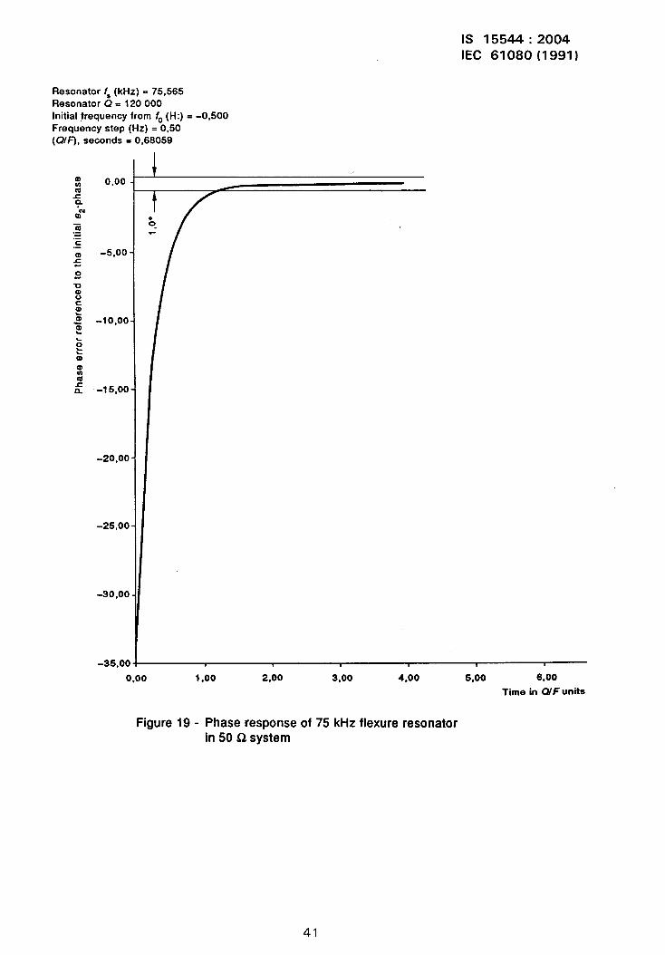
Figures 16 and 17 show a simulation of the response of a crystal unit connected in a 50 Qtransmission system. It is assumed that the initial frequency was stabilized, and at timet = O, the synthesizer was set to a new frequency without any discontinuity of either ampli-tude or phase - a “perfect” synthesizer. The time scale has been normalized to units ofQ/f~of the crystal unit, as these are values which would normally be known approximatelyfor a crystal unit being measured. The horizontal lines represent dev~ations from the finalsteady state response of A0,5 ‘Yo amplitude and A0,5” phase, which are considered to bethe minimum accuracy required for a precision measurement. Figures 18 and 19 aresimilar plots for a crystal unit having very different parameters; in terms of Q/fS, however,the settling time required is about the same. It is clear that instrument switching time andsettling time as well as device settling time shall all be taken into consideration in themeasurement programme.
14 Measurement methods In the production environment
Test and measurement of crystal units in a production facility pose some specificproblems. Generally, high throughput is required and devices are checked against speci-fied tolerances on a “go” or “no-go” basis. In most cases not all parameters are specified,and therefore testing may be limited to include only those specified parameters together
21

IS 15544:2004IEC 61080(1991)
with any additional measurements needed to assess the general quality of the product.Obviously, all devices need to be tested against specified parameter value tolerances;quality assessment, however, may be implemented on a sampling basis, especially ifproduction quantities are large.
The equipment used for production testing can be selected on the basis of device require-ments; i.e. if only frequency and resistance are specified, then relatively simple oscillatoror transmission test facilities are adequate. The degree of automation of the testequipment will depend upon the quantity of product involved. The advantages of highercapacity and better reproducibility of data resutting from automated testing are usuallysufficient justification in themselves. When some portion of the product requires measure-ment of L, (Cl) values, and/or determination of load parameters, fL, RL and SL, the one- ortwo~port S-parameter equipments will provide relatively fast measurement of all para-meters without the need for additional test fixtures, and therefore will be a good choice.The one-port reflection equipment requires less measurement time than two-port systemsbut has other limitations, as previously discussed. The automated transmission type equip-ments are particularly suited to applications requiring temperature testing of devices.
Regardless of the test methods chosen for the production floor, it is advisable that at leastone system be available which will permit complete characterization of a device, withmeasurements referred to acceptable, traceable impedance and phase standards. W4hthis system, checks of calibration and accuracy of the production test equipment can beregularly conducted, and/or sampling tests of production units may be carried out to track,on a statistical basis, both the product performance and the validity of the production testequipment. The key to success is a regularly scheduled “calibration” of the production testequipment in terms of transfer standards which are referenced to the standard system,which, in turn, is calibrated to traceable impedance and phase standards.
15 Conclusion
In summary, the complete characterization of the static and motional equivalent electricalparameters of quartz crystal units is not a trivial undertaking. Several possible methods ofmeasurement have been described in general terms, and brief descriptions of data reduc-tion methods given for those automated systems offering the best obtainable accuracy andprecision.
Very little has been said here about the very significant problem of providing adequate testfixtures, nor have the questions of temperature-testing, unwanted mode scanning, anduse-circuit characterization been addressed here. These questions present as muchdifficulty as the selection of basic measuring methods and need to be carefully consideredin practice.
22
IS 15544:2004IEC 61080(1991)
16 Blbliographle - Blbllography
[1] IEC Publication 302: LMfh?itions normalisdes et m&hodes de mesure pour /esrt?sonateurs pk?zo~lectriques de frdquences inf&ieures ~ 30 MHz - Standarddefinitions and methods of measurement for piezoelectric vibrators operating overthe frequency range up to 30 MHz, 1969.
[2] IEEE Standard No. 177: Standard definitions and methods of measurement forpiezoelectric vibrators, 1968.
[3] Gerber E.A. A review of methods for measuring the constants of piezoelectric vibra-tors, Proc. IRE, v. 41, No. 9, p. 1103, September 1953.
[4] Hafner E. The piezoelectric crystal unit: Definitions and methods of measurement,Proc. IEEE, v. 57, No. 2, p. 179, February 1969.
[5] Malinowski G. and Hafner E. Automated microcircuit bridge for measurement ofquartz crysta/ units, Proc. Sznd Annual Frequency Control Symposium (AFCS),p. 354, 1978.
[6] Smythe R.C. An automated resonator measurement system using a reflection weffi-cienf bridge, Proc. 35th AFCS, p. 280, 1981.
[7] Malinowski G., Snider G. and Nyholm C. /mp/ementation of an automatic microcircuitmeasuring system for quartz crysta/, Proc. 35th AFCS, p. 286, 1981.
[8] Hotton W., Payne T., Smythe R.C. and Symonds D. Comparison of methods formeasurement of quartz crystal resonators with load capacitance, Proc. 35th AFCS,p. 271, 1981.
[9] Geldart W., Haynie G. and Schleich R. A 50 Hz -250 MHz computer operated trans-mission measuring set, BSTJ, v. 48, No. 5, p. 1339, May-June 1969.
[1O] Pusterfi H.S. and Smith W.L. An automated crystal measuring system, Proc. 27thAFCS, p. 88, 1973.
[11] Peach R.C., Dyer A.J. et al., New method for the measurement of quartz crysta/resonator parameters, Proc. 36th AFCS, p. 297, 1982.
[12] Smolarski A.J. and Wojcicki M.S. Quartz crystal measurement system based ontransmission line T-network, IEEE Trans. SU, No. 25, p. 300, 1978.
[13] Smolarski A.J. and Wojcicki M.S. Extension of frequency range of quattz c~sta/measurement method based on transmission line T-network, IEEE Trans. SU,September 1981.
[14] Smith W.L. An overview of a proposed standard method for the measurement of theequivalent circuit parameters of quartz crystal units up to 1 GHz, Proc. 6th QuartzDevices Conference, p. 1, 1984.
[15] Smith W.L. EIA standard 512: Some further diswssion and comment, Proc. 7&Quartz Devices Conference, p. 13, 1985.
[16] Semones Timothy, Software implementation of E/A 512, Proc. 8th Quartz DevicesConference, p. 108, 1986.
[17] Smith W.L. Final repcd, P-11 round robin crystal measurement experiment, Proc.10th Quartz Devices Conference, p. 51, 1988.
23
IS 15544:2004IEC 61080(1991)
cPP
R,
c,~R 4) d)
pl Lpl II $* %21 0 II 2
R L*,I %.1 1.1
4 II )
I %2 C,* ‘1s ]
Lfvk-i*’R C,N 1.Nl,N ,
:C pl c●1 =C
●2 cp2= =
9 0 0 3
NOTE - This network is valid up to 35o MHz.
Figure 1- Nearly exact equivalent electrical networkof a piezoelectric quartz resonator
24
Is 15544:2004IEC 61080(1991)
Figure 2a - Equivalent network adequate for most applications.Three-terminal, two-porl model suitable over a
bandwidth of * a few percent from OS= 1 / ~
J-”NOTE - This network is valid up to 200 MHz.
Figure 2b - Two-terminal representation when enclosure is not grounded.C13 and C23 are included in the Covalue
RI
~1 c’
Figure 2C - Simple two-terminal equivalent network, useful oververy narrow bandwitdh when Co may be neglected
Figure 2- Simplifications of the equivalent electrical network
25

,
1S 15544:2004IEC 61080 (1991)
+B
@,co
o
-B
/\
‘“’z\H
————___ ___ ,___, Y
Figure 3- Loousof a cfystal unittransadmittancefunctionin the Y-plane(when no shuntoonductanoeGOis present) showingthe pointscorrespondingto the fwe charaoterfsticfrequencies
26
R
o
IS 15544:2004IEC 61080(1991)
II
Ill
II
II
I It
II M-
Ill I111 IIII
), II
II+
x
I
o 1
t
A IIIll
Izl Ill
o i
Figure 4-
fm f, f, fa f“
Impedance versus frequency characteristics of a quartzcrystal unit near resonance
27
1S 15544:2004IEC 61080(1991)
7 Counter
/Amplifier Phase
adjuster4b Level
meter1~2
T
Figure 5a - Oscillator test circuit for crystal units(~ and 1?,)
f———. ——— ——— ——— ——— ——.
I t(AGC)
Counter i
IAmplifier ‘ Phase
adjuster I
f + Level
e, ,*2 e,-J
meter
o I
RT
Vectordetector
Figure 5b - Modifications to oscillator methodfor improved accuracy and precision
c.
+-J—IQ
Figure 5C - Determination of fL and RL requires test fixturewith added series capacitor
Figure 5- Some possible oscillator test circuit configurationsfor crystal resonator measurements
28
IS 15544:2004IEC 61080(1991)
F1 2
Tuneable Levelsource adjustment
1
Frequency Vectorcontrol signal detector
Figure 6- Transmission measurement method for crystal resonators
r -.
IS 15544:2004IEC 61080(1991)
For a single-port measurement (reflection), the equivalent circuit is as shown in figure 7.
1
m
L,
co c1 GO. LR.
RI
2
?
Figure 7
For a two-port measurement on a single resonator, the circuit is as given in figure 8.
+
Figure 8
30

IS 15544:2004IEC 61080(19911
dB o *... **.*0*0****. . . . .. OO.00.... -0.......9.*.....****
-lo -
-20 -
-30 -
40 -
-50 -
-60 .
-70 -
*27,516 27.526 27.535
Frequency, MHz
Number of calibration frequencies:
Frequency point file:
Error parameter file:
Calibration date:
Measurement demo:
Crystal No.:
Temperature:
Start frequency:
Stop frequency:
No. of measured frequency points:
Result calculated using one point in:
Synthesizer level:
Frequency (MHz) Co (pF) Rm(Q)27,5262301 3,19 15,61
AF (Hz)= 0,000 ACO(PF) = 0,464
Load resonance frequency:f(20) = 27,533329 MHz430) = 27,531 t90 MHz
100
F5-600
ER5-600
16 Juiy 1984
16 July 1984
#37
23,2 “C
27,516000 MHz
27,535000 MHz
100
5
-4,0 dBm
Lm (mH) Cm(pF) Q P (pw)2,7948 1,19617E-02 30957 9,19
Al?m(Cl) = 0,515 ALm (mH) = 0,00000
Pulling sensitivity:S(20) = -11,1206 l“E-61pFS(30) = -5,4291 l* E-61pF
Figure 9- Reflection measurement
31

IS 15544:2004IEC 61080(1991)
dB Oi’ .**”..
-10-20
-30
+0
-50
-60
-70L..*
27,5
Number of calibration frequencies:
Frequency point file:
Error parameter file:
Calibration date:
Measurement demo:
Crystal No.:
Temperature:
Start frequency:
Stop frequency:
No. of measured frequenoy points:
Result calculated using one point in:
Syntfresizer level:
Frequency (MHz) Co (pF) Rm(Q)27,5263940 2,56 15,77
AF (Iiz) = 0,017 ACO(PF) = 0,022
Load resonance frequenoy:f(20) = 27,=3400 MHzI’(3O)= 27,531248 MHz
27,55 27,6
Frequency, MHz
100
F5-600
ET5-600
16 &dy 1984
16 July 19S4
#37
23,2 “C
27,600000 MHz
27,600000 MHz
100
6
-0,3 dBm
Lm(mH) Cm(pF) Q P (pw)2,9118 1,1481 OE-O2 31934 6*98
Al?m(Q) = 2,135 ALm (mH) = 0,00002
Pulling sensitivity:S(20) = -11,2833 l“E-6/pFS@) = - 5,4162 l“E-6/pF
Figure 10- Transmission measurement
32

.
1S 15544:2004IEC 61080(1991)
IFrequency {jsynthesizer
T
@$ ()’ courbes
Printer/plotter
Network -analyzer {, j
?? Wmw=Ym
44
S-parameter + (,]bridge b T ? t
Device under test
I </\/
Temperature meaauringdevice
Figure 11-. Instrumentation block diagram
33
1S 15544:2004IEC 61080(1991)
Reference line
Synthesizer — Level Powersourc adjustment splitter
4 po~Vectordetector
1
Control Control
Control
Y
Data
4i
I Computer
m “atas’o’”eI
I! 1
Printer Terminal Plotter
Figure 12- Automation of the transmission measurement method
34

IS 15544:2004IEC 61080(1991)
I R6ference signal
Power
I splitter
Synthesizersource
4Cent rol
\
Control
Vector
r
IL
II 1.I
1- ——. ——
Computer
d-
directionalcoupler
Control
I
Control
Data
Figure 13- Automatic reflectometer impedancemeasurement method
35
IS 15544:2004IEC 61080(1991)
F?,
RI
R,
t
/
//
correc~~ for co---#/
// Measured
~/
/“-
* I
~1
/
III
I s
t~
+
Measured—— —— ——8 s
8
I kII
co
ICorrectd for
10 1 t 1
f, f,-
f
Measured Y12=G12+iB12
Corrected for CO,~z = B12- ~. Co
and Y,> = G12 + N;
Fitted polynomial interpolation functionsprovide data smoothing.
Figure 14- Derivation of motional parameters from transadmittancemeasurements
36
.
IS 15544:2004IEC 61080(1991)
x, t
1CO*CL
o
R.“1
o
Reactance
—— —— —— —. .—
u
I
If Af
t ./”Resistance
I ‘f’
.—. —— — —— .
II
I I
Figure 15- Derivation of load parameters from measured transadmittanceabove resonance:
1 Gz 12 jB12
12=—= =R~+jX~Y12
G,;+ B;2 G1~+ B~2
Fitted polynomial interpolation functions providedata smoothing.
37

r---t
IS 15544:2004IEC 61080 (1991)
Resonator f, (kHz) = 5000,085Resonator Q = 2500000Initial frequency from f. (H:) = -2,000Frequency step (Hz) = 2,10(QIF), seconds = 0,26190
(D0,18
mcoso.
+s
0,17=
$
0.16
0.15
0,14
0.13
0,12
0.11
0,00
Figure 16-
1.00 2,00
Amplitude responsein 50 Cl system
3.00 4,00 5,00 6,00
Time in ~F units
of 5 MHz, 5th overtone resonator
38

- -q
IS 15544:2004IEC 61080(1991)
Resonator f. (kHz) = 5000,085Resonator C?= 2500000Initial frequency from f. (H:) = -2;000Frequency step (Hz) = 2,10(C)IF), seconds = 0,26190
I 10,00- /
00-
-8,00-
-16,00-
-24,00-
-32,00-
40,00.
48,00-
-56,00+ I , , 1 ‘0,00 1,00 2,00 9,00 4*OO 5.00 6,00
Time in W F unfts
Figure 17- Phase response of 5 MHz, 5th overtone resonator,in 50 Q system
39

IS 15544:2004IEC 61080(1991)
Resonator f, (kHz) = 75,565Resonator Q = 120000Initial frequency from f. (H:) = -0,500Frequency step (Hz) = 0,50(CUF), seconds = 0,66059
0,22emc
g@.
fj0,21
=
2<
o,2a
0,19
0,18
0,17
0,16
0.15
1
0,00 1.00 2,00 3,00 4,00 5,00 6.00
Time in CYFunits
Figure 18- Amplitude response of 75 kHz flexure resonatorin 50 Q system
40
---
IS 15544:2004IEC 61080(1991)
Resonator f, (kHz) = 75,565Resonator= 120000Initial frequency from f. (H:) = -0,500Frequency step (Hz) = 0,50(QIF), seconds = 0,68059
I
am 0,002n“m0
ii.-.=c.-
-5,002
-lo,oa
~to
E -I 5,0a
-20,0C
-25,0(
-30,0(
-
-35,0a
0,00 1,00 2,00 3.00 4.00 5,00 6,00
Time in Q/F units
Figure 19- Phase response of 75 kHz flexure resonatorin 50 Q system
41

Is 15544:2004IEC 61080(1991)
Annex A
Classification of quartz crystal unitmeasurement systems
Electrical parameters of quartz crystal units under constant measuring conditions may beclassified into three distinct groups:
i) Parameters characterizing desired (main) resonance; these parameters associatedwith the main motional arm of the equivalent circuit are of major importance.
ii) Parameters characterizing unwanted modes.
iii) Parameters characterizing the remainder of the equivalent circuit.
In some cases the so-called “load” parameters characterizing the equivalent circuit of aquartz crystal unit connected in series with an external circuit (usually capacitive) are alsoneeded.
In the general case the quartz crystal unit must be treated as a three-terminal network, thethird terminal being in the typical case a metal enclosure, which should be grounded.Three types of connection of the crystal unit are possible:
one-port (two-terminal) connection in which one of the pins (leads) is groundedwhile the enclosure is floating;
- one-port (two-terminal) connection in which one of the pins (leads) is grounded andthe enclosure is also grounded;
two-port (three-terminal) connection in which only the enclosure is grounded.
The true values of the motional arm parameters of the quartz crystal unit equivalent circuit(for the main resonance: series resonance frequency f,, motkmd resistance ~1 and
motional capacitance Cl or inductance L,) are practically independent of the tyPe ofconnection. However, the type of connection strongly influences the distributed (static)capacitances CAB, CA~ and CB~.
In the one-port connection, the effective shunt capacitance CO is to a first approximationthe sum of the capacitance CABbetween the pins of the unit and the capacitance CAH (orCBH) between the ungrounded pin and ground. The influence of distributed capacitance isdifferent in various measuring methods and different applications, so it is important tospecify the crystal unit lead connection to be used.
In general, the characterization of a quartz crystal unit requires many rather complexmeasurements to be made at different frequencies near series resonance, to form anestimate of the equivalent circuit parameters which will best approximate the electricalbehaviour of the unit. Fortunately, in most cases only a few of the crystal unit equivalentparameters need to be determined, particularly in the production environment.
The two most important parameters are: the series resonance frequency f~ and themotional resistance RI. In a large number of cases, these may be approximated bymeasurement of zero-phase frequency fr and zero-phase insertion resistance f?r. Theselatter two parameters may be measured with a limited accuracy by simple and fast sing/efrequency methods (see clause 7).
42

IS 15544:2004IEC 61080(1991)
More complex characterization of crystal units requires the use of several measurementfrequencies, so rmdti-frequency methods are used.
From the point of view of general principles the most important measuring methods maybe classified as follows:
i) Osci//atormethods (also called active methods) in which the frequency of oscillationof special oscillator circuits, into which the crystal unit to be measured is connected, ismeasured and assumed to be the zero-phase frequency of the crystal unit.
ii) Transmission methods in which the crystal unit parameters are determinedindirectly from measurements of the transfer function of the network formed by connect-ing the crystal unit (enclosure grounded) into a resistive network. Transmissionmethods may be divided into four sub-groups:
a) Extremurn transmission methods (ETM) in which only information about themagnitude of the transfer function is used. The crystal unit frequency is identified asthat at which the extremum (maximum) output voltage occurs.
b) Phase transmission methods (PTM) in which information about the transfer func-tion phase is used. The crystal unit frequency is identified as that at which theoutput voltage phase is the same as that obtained during preliminary calibration (inthe ideal case, the output voltage is in phase with the input voltage). In thesemethods amplitude information is not needed to establish frequency of the unit, butmust be obtained if the insertion resistance is to be calculated.
Measuring sets using m or T-transmission networks are the most important exam-ples of equipment used for ETM or PTM.
c) Vector transmission methods (VTM) in which information about both the ampli-tude and phase of the transfer function is needed. In contrast to the ETM and PTM,which are fundamentally single frequency measurements, VTM typically requiremeasurements at severai frequencies near resonance so that motional capacitance(or inductance) may also be determined.
d) Scattering parameter methods (SPM) in which all four of the two-port scatteringparameters of the three-terminal crystal unit connection are determined, and fullycorrected for linear errors in measuring system and fixtures, at several frequenciesnear series resonance of the device. Such measuring sets require the use of dual-directional couplers and vector detectors, such as those incorporated in networkanalyzers.
iii) Impedance (admiffance) measuring methods in which one-port quartz crystal unitparameters are determined using the vector values of the crystal unit impedance (admit-tance) measured at several frequencies near resonance. The method of calculation isthe same as for the SPM above, but the crystal unit is connected as a one-port (withone pin/lead grounded). Two sub-groups of impedance measurement may be distin-guished:
a) Direct immittance methods (DIM) in which equipment is used which reads outdirectly impedance (or admittance) values (e.g., various bridges or vector immit-tance meters).
43
IS 15544:2004IEC 61080(1991)
b) F?ef/ectioncoefficient methods (RCM) in which the quartz crystal unit parametersare determined from the vector values of the reflection coefficient of the crystal unitconnected to a system port of known impedance, at several frequencies.
Various equipments measuring the complex reflection coefficient may be used inRCM. The most important are: sets containing directional coupler (or reflectometer)with a vector voltmeter, impedance meters utilizing directional bridges and sometypes of vector network analyzers.
Motional capacitance (inductance) may be calculated utilizing measurements of quartzcrystal units at more than one frequency. Most important are three groups of methods:
i) Load capacitor methods (LCM) in which changes in resonance frequency due to theconnection of load capacitances in series with the crystal unit are measured, and themotional capacitance calculated from the frequency difference.
ii) Transfer function methods in which frequencies corresponding to chosen points onthe transfer function versus frequency curve of the transmission network containing thecrystal unit are determined. Two sub-groups of these methods are the most important:
a) Phase offset methods (POM) in which two frequencies corresponding to twoequal (but opposite in sign) values of transfer function phase are measured.
b) Magnitude offset method (MOM) in which two frequencies on opposite sides ofthe crystal unit resonance frequency with the same chosen value of transferfunction magnitude are measured.
iii) Admittance (impedance) methods in which frequencies corresponding to chosenpoints of the admittance (impedance) versus frequency curve are measured. The mostimportant sub-groups of these methods are:
a) /remittance phase methods (1PM) in which frequencies corresponding to chosenvalues of crystal immittance phase are used to calculate motional capacitance Cl(motional inductance l.,).
b) /remittance magnitude methods (lMM) in which frequencies corresponding tochosen values of crystal unit immittance magnitude are used to calculate Cl (Ll).
c) Computer aided methods (CAM) in which various algorithms are used toestimate Cl (Ll) from the immittance values measured at several frequencies nearthe series resonance frequency of the crystal unit. One of the more important ofthese methods uses the slope of the motional arm reactance versus frequencycurve at the point of zero reactance.
The effective shunt capacitance Co (for one-port quartz crystal unit connection) or thethree capacitances CAB = Co, CAH and CBH (for two-port connection) are typicallymeasured at low frequencies using appropriate capacitance bridges (LFM). In somemeasurement methods it is possible to measure the values of these capacitances atfrequencies near the nominal frequency of the quartz crystal unit (HFM); this possibility isimportant for crystal units operating at high frequencies (i.e. 100 MHz or above) as theeffective values of Co change with frequency due to stray inductances and capacitances ofthe mounting system.
44
IS 15544:2004IEC 61080(1991)
TABULATION OF MEASURING METHODS
(A table of measuring methods is given on pages 93 to 97)
General assumptions:
. the main reason for the measuring method tabulation is to facilitate the preliminarychoice of method;
- the structure of the table should allow the addition of new methods;
. the table should contain all the methods recommended or considered by IEC Tech-nical Committee No. 49*;
other methods used in practice in various countrie$. and recommended by nationalstandards or industrial standards should also be included;
- the table should be maximally concise.
The accuracy of quartz crystal unit parameter measurements depends on many factors,including both the effects of other parameters of the crystal unit and the characteristics ofthe measurement equipment used. Among the most important factors are:
nominal frequency of the crystal unit;
crystal unit quality factor;
effective shunt capacitance of the crystal unit;
. uncontrolled stray reactance associated with the test fixtures and the crystalenclosure;
- temperature of the crystal unit and the measuring equipment;
control of the drive level applied to the crystal unit during test.
Due to the very broad range of parameter values for quartz crystal units of various designsit is not possible to give accurate estimates of the accuracy obtainable with a particularmethod of measurement. Instead, it is proposed to use in the table three grades ofaccuracy: low, medium and high.
For typical quartz crystal units in the frequency range from about 1 MHz up to approxi-mately 100 MHz intended for use in crystal-controlled oscillators “low” corresponds tofrequency accu-rac not better than about 5 x 10⁻⁶; “
2medium” to a range of accuracies of
about 1 to 5 x 10- and “high”to accuracies better than about 1 x 10⁻⁶.
Abbreviations used:
General:
1P = crystal unit measured in one-port configuration;
●
See the inside and outer back covers of this standard.
45

IS 15544:2004IEC
2P
()
IF
2F
3F
MF
1:
u
low
61080 (1991)
mediumhigh
crystal unit measured in two-pod mnnection;
frequency range in megahertz;
one-frequency method;
two-frequency method;
three-frequency method;
multi-frequency method;
method intended for mea!$urement of the quantity given after the column;
method useful but not especially intended (in most cases existing documents donot specify detailed measuring procedures and accuracy is often unknown ordifficult to determine);
= comparative rating of measurement accuracy.
Frequencies:
f~
fr
fm
fmT
fnT
$
fL
fN
1series resonance frequency ‘S=
2z~;
resonance frequency (zero insertion phase);
frequency of maximum admittance;
frequency of maximum transmission;
frequency of minimum transmission;
frequency of transfer function zero phase;
load resonance frequency;
unwanted mode frequency.
Resistances:
RI =
R, =
RL =
motional resistance;
resonance resistance (insertion resistance at zero phase);
load resonance resistance;
46
IS 15544:2004IEC 61080(1991)
RN = unwanted mode resistance.
Clll-l measuring methods:
LCM = load capacitor method;
POM = transfer function phase offset method;
MOM = transfer function magnitude method;
1PM = immittance phase method;
IMM = immittance magnitude method;
CAM = computational method.
COmeasuring methods:
LFM = low frequency method (below 1 MHz);
HFM = high frequency method (near crystal unit operating frequency or above).
47
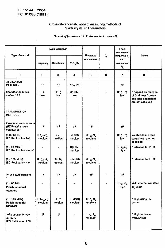
.
1S 15544:2004IEC 61080(1991)
Cross-referencetabulationof measuringmethodsofquartz crystalunit parameters
(Asterisksr]in columns1 to 7refer tonotesin column8)
Main resonance Loadresonance
Type of method Unwanted co frequency~ Notea
resonances and
Frequency Resistamx C1/L@ resistance
4
1 2 3 4 5 6 7 8
3SCILLATORMETHODS IF lF 3F or 2F lF
Srysta/ impedance 1: f, 1: R, U(LCM) - U: f~, RL “ Depend on the typeneters ● 2P low low low low of CIM; test fixtures
and load capacitorsare not specified
rRANSMISSIONWETHODS
Fxtremum transmission
‘ETM) with K-type IF lF 3F IF lFTetwork 2P
s 30 MHz) 1: fmT<fm 1:RI I(LCM) U: fN,RN - U: f~, RL x-network and loadEC Publication 302 medium medium medium medium low capacitors are not
specified
1-30 MHz) U(LCM) - U: fL,RL ● Intended for PTMEC Publication 444-4” medium high
1-125 MHz) u: fmT<fm U: RI U(MOM) U: fN,RN “ Intended for PTMEC Publication 444” medium medium medium medium
With T-type network lF IF 3F IF lF1P
[1 -60 MHz) 1: f~, RL With internal constant
Polish Industrial high CLvalueStandard
[1 -125 MHz) 1:f<fm<f, 1:Rf U(MOM) U: fN,RN ● High using FMPolish Industrial medium medium medium mediumStandard
variant
With special bridge u u 1:fN,RN ● High for lowernetwork medium” frequenciesIEC Publication 283
48
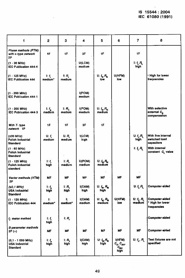
IS 15544:2004IEC 61080(1991)
I
r
1 2 3 4 5 6 7 8
Phase methods (PTM)with x-type network IF lF 3F lF IF2P
[1 -30 MHz) U(LCM) 1: fuRLIEC Publication 444-4 medium high
:1-125 MHz) 1: f, 1:R, U: fN,RN U(HFM) ● High for lowerEC Publication 444 medium* medium low low frequencies
;1 -200 MHz) I(POM)IEC Publication 444-1 medium
[1 -200 MHz) 1: f 1:RI I(POM) U: fN,RN With selectiveIEC Publication 444-3 medi?im medium medium medium external Co
compensation
With T- type lF lF 3F lFnetwork 1P
[s30 MHz) u: f, U: R, I(LCM) U: fuRL With five internalPolish Industrial medium medium high highStandard
switched loadcapacitors
[1 -60 MHz) 1: fL,RL With internalPolish Industrial constant CL valueStandard
[1 -125 MHz) 1: f, 1: R, U(POM) u: fNp~Polish industrial high medium medium mediumstandard
Vector methods (VTM) MF MF MF MF MF MF2P
(s0,1MHz) 1: f, k R, I(CAM) lf: fN.RN U:fuRL Computer-aided
USA Industrial high high high highStandard
[1 -125 MHz) 1: 1: I(CAM) U: fN,RN U(HFM) U: fL.R~ Computer-aided
IEC Publication 444 medium” medium* medium medium low msdium “ High for lowerfrequencies
~ meter method 1: f, k R, Computer-aided
high
S-paramater methods2P (+) MF MF MF MF MF MF Computer-aided
(0,1 -1000 MHz) 1: f, 1:RI I(CAM) U: fN,RN I(HFM) U: f~, RL Test fixtures are not
USA Industrial high high high high co,CM, specified
Standard cIt&
49
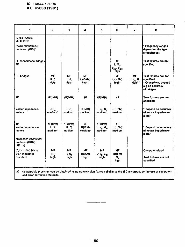
IS 15544:2004IEC 61080(1991)
1
IMMITTANCEMETHODS
Direct immittancemethods (DIM)*
LF capacitance bridges2P
HF bridges
1P
Vector impedance-meters
1PVector impedance.meters
Reflection coefficien tmethods(RCM)1P (+)
(O,1-1OOOMHZ)USA IndustrialStandard
2
MFu: f,high*
lF(IMM)
u: fmmedium*
lF(IPM)u: f,
medium*
MF1:f~high
3
MFU: RIhigh*
lF(IMM)
U: RImedium*
lF(IPM)U: R,
medium*
MF1:RIhigh
4
MFU(CAM)
high*
3F
U(IMM)medium*
3FU(IPM)
medium*
MFI(CAM)
high
5
lF(IMM)
U: fN,RNmedium”
lF(IPM)U: fN, RNmedium*
MFU: fN, RN
high
6
IF1:Cv
:AB,CBH,high
MFU(HFM)high*
lF
U(HFM)medium
lFU(HFM)medtum
MFI(HFM)
chi:il
7
MFU: fL, RL
high*
8
‘ Frequency rangesdepend on the typesf equipment
rest fixtures are notspecified
Test fixtures are notspecified‘ Or medium, depend-ing on accuracyof bridges
Test fixtures are notBpeCified
* Depend on accuracyDfVeCtOrimpedance-meter
‘ Depend on accuracyof vector impedance-meter
Computer-aided
Test fixtures are notspecified
(+) Comparable precision can be obtained using transmission fixtures similar to the IEC x-network by the use of computer-ised error correction methods.
50

Bureau of Indian Standards
BIS is a statutory institution established under the Bureau ot/ncfian Standards Act, 1986 to promoteharmonious development of the activities of standardization, marking and quality certification ofgoods and attending to connected matters in the country.
Copyright
BIS has the copyright of all its publications. No part of these publications maybe reproduced in anyform without the prior permission in writing of BIS. This does not preclude the free use, in the courseof implementing the standard, of necessary details, such as symbols and sizes, type or gradedesignations. Enquiries relating to copyright be addressed to the Director (Publications), BIS.
Review of Indian Standards
Amendments are issued to standards as the need arises on the basis of comments. Standards arealso reviewed periodically; a standard along with amendments is reaffirmed when such reviewindicates that no changes are needed; if the review indicates that changes are needed, it is takenup for revision. Users of Indian Standards should ascertain that they are in possession of the latestamendments or edition by referring to the latest issue of ‘BIS Catalogue’ and ‘Standards : MonthlyAdditions’.
This Indian Standard has been developed from Doc : No, LTD 12 ( 1961 ).
Amendments Issued Since Publication
Amend No. Date of Issue Text Affected
BUREAU OF INDIAN STANDARDS
Headquarters:
Manak Bhavan, 9 Bahadur Shah Zafar Marg, New Delhi 110002Telephones :23230131, 23233375, 23239402 Website : www.bis.org.in
Regional Offices :
Central :
Eastern :
Northern :
Southern :
Western :
Branches:
Manak Bhavan, 9 Bahadur Shah Zafar MargNEW DELHI 11 OOO2
1/14 C. 1. T. Scheme Vll M, V. 1. P. Road, KankurgachiKOLKATA 700054
SCO 335-336, Sector 34-A, CHANDIGARH 160022
C. 1.T. Campus, IV Cross Road, CHENNAI 600113
Manakalaya, E9 MlDC, Marol, Andheri (East)MUMBAI 400093
Telephones
{2323761723233841
{23378499,2337856123378626,23379120
{26038432609285
{2254 1216, 2254 14422254 2519, 2254 2315
{
28329295,2832785828327891,28327892
AHMEDABAD. BANGALORE. BHOPAL. BHUBANESHWAR. COIMBATORE.FARIDABAD. GHAZIABAD. GUWAHATI. HYDERABAD. JAIPUR. KANPUR.LUCKNOW. NAGPUR. NALAGARH. PATNA. PUNE. RAJKOT. THIRUVANANTHAPURAM.VISAKHAPATNAM.
Printedat New India PrintingPress, Khurja,India