IQ Range Installation and Maintenance Instructionsmsp-maad.com/userfiles/file/ROTORK/e170e3.pdf ·...
92
IQ Range Installation and Maintenance Instructions This manual contains important safety information. Please ensure it is thoroughly read and understood before installing, operating or maintaining the equipment. Publication number E170E3 Date of issue 10/05
Transcript of IQ Range Installation and Maintenance Instructionsmsp-maad.com/userfiles/file/ROTORK/e170e3.pdf ·...

IQ RangeInstallation andMaintenance Instructions
This manual contains important safety information. Please ensure it is thoroughly read and understood before installing, operating or maintaining the equipment.
Publication number E170E3Date of issue 10/05

The Rotork Setting Tool allows actuator control, indication and protection functions to be configured to suit site requirements. In addition, the new Setting Tool Pro also allows downloading of datalogger and uploading/downloading of configuration files. Files are transferred to and from the Setting Tool Pro via Rotork Insight.
It is essential that all the actuator settings are checked for compatibility with the valve, process and control system requirements before the actuator is put into service. Please read this publication.
When Rotork personnel or nominated agents are contracted to carry out site commissioning and/or acceptance, documentation of commissioned actuator configuration can be made available for customer records.
Rotork Setting Tool Pro
Rotork Setting Tool

This manual provides instruction on:
* Manual and electrical (local and remote) operation.
* Preparation and installation of the actuator onto the valve.
* Subsequent commissioning and adjustment of the Basic Settings for correct valve operation.
* Commissioning and adjustment of the Configuration Settings to suit site-specific control and indication requirements.
* Maintenance – Troubleshooting.
* Sales and Service.
Refer to Publication E180E2 for repair, overhaul andspare part instructions.
THE ROTORK IQ RANGE – THE FIRST VALVE ACTUATOR THAT YOU CAN COMMISSION AND INTERROGATE WITHOUT REMOVING ELECTRICAL COVERS.
Using the supplied infra-red Setting Tool to access the actuator set upprocedures, non-intrusive setting of torque levels, position limits and all other control and indication functions can be made safely, quickly andconveniently, even in hazardous locations. The IQ allows commissioningand adjustment to be carried out with the main power supply to theactuator switched on or off.
Standard diagnostics access information about the control system, valveand actuator status is in the form of display text and help screens.
Setup, Alarm and Status text is available in English (default), Spanish, French and German.
Instantaneous valve torque and position can be monitored on the actuatorwith a single key press of the Setting Tool.
The on board Datalogger captures operational and valve torque dataenabling informed maintenance choices to be made. IQ Insight softwarefor PC and PDA allows the Datalogger to be interrogated, as well as the complete actuator set up to be configured and recorded.
The actuator containing the Setting Tool will be identified with a yellowlabel on the terminal cover.
Visit our web site at www.rotork.com for more information on the IQ, IQ Insight and other Rotork actuator ranges.


1
Page
1 Health and Safety 2
2 Storage 3
3 Operating your IQ Actuator 3 3.1 Operating by Hand 3 3.2 Operating Electrically 3 3.3 Display – Local Indication 4 3.4 Display Status Indication – Travel 5 3.5 Display Status Indication – Control 5 3.6 Display Alarm Indication 5
4 Preparing Drive Bush 7 4.1 IQ10 to IQ35 7 Thrust Base Types A and Z 4.2 IQ10 to IQ35 8 Non-Thrust Base Type B 4.3 IQ40 to IQ95 8 Thrust Base Types A and Z 4.4 IQ40 to IQ95 9 Non-Thrust Base Type B
5 Mounting the Actuator 10 5.1 Rising Stem Valves – Top Mounting 11 5.2 Valve with Gearbox – Side Mounting 12 5.3 Non-Rising Stem Valves – Top Mounting 12 5.4 Handwheel Sealing 12
5.5 IQM Modulating Actuators 12 5.6 IQML Linear Drive Unit 12 5.7 IQML Adjusting Linear Stroke 13
6 Cable Connections 14 6.1 Earth/Ground Connections 14 6.2 Removing Terminal Cover 14 6.3 Cable Entry 14 6.4 Connecting to Terminals 15 6.5 Replacing Terminal Cover 15
7 Commissioning 16 7.1 The Setting Procedure 16 7.2 The Rotork Setting Tools 17 7.3 Entering the Actuator 20 Setting Procedure 7.4 Setting Mode – Password 20 7.5 New Password 20 7.6 Checking Mode 20 7.7 Crossroad 21 7.8 The Actuator Display – 21 Setting/Checking Mode 7.9 Returning to Valve Position Display 21
8 Commissioning – Basic Settings 22 Basic Settings Contents 23
9 Commissioning – Configuration Settings 31 Configuration Settings Contents 33 Default Options 63
10 Maintenance, Monitoring and Troubleshooting 65 10.1 Setting Tool Pro Download & Upload 68 10.2 Help Screens 71 10.3 IQ Infrared Diagnostic & Configuration 76 10.4 Environmental 77
11 Weights and Measures 78 Binary, Hexadecimal and Decimal Conversion Table 79
12 IQ Approvals 80
CONTENTS
Page
Page

2
This manual is produced to enable a competent user to install, operate, adjust and inspect Rotork IQ range valve actuators. Only persons competent by virtue of their training or experience should install, maintain and repair Rotork actuators. Work undertaken must be carried out in accordance with the instructions in this and any other relevant manuals. The user and those persons working on this equipment should be familiar with their responsibilities under any statutory provisions relating to the Health and Safety of their workplace. Due consideration of additional hazards should be taken when using the IQ range of actuators with other equipment. Should further information and guidance relating to the safe use of the Rotork IQ range of actuators be required, it will be provided on request.
The electrical installation, maintenance and use of these actuators should be carried out in accordance with the National Legislation and Statutory Provisions relating to the safe use of this equipment, applicable to the site of installation.
For the UK: Electricity at Work `Regulations 1989 and the guidance
given in the applicable edition of the “IEE Wiring Regulations’’ should be applied. Also the user should be fully aware of his duties under the Health and Safety Act 1974.
For the USA: NFPA70, National Electrical Code ® is applicable.
The mechanical installation should be carried out as outlined in this manual and also in accordance with relevant standards such as British Standard Codes of Practice. If the actuator has nameplates indicating that it is suitable for installation in hazardous areas then the actuator may be installed in Zone 1, Zone 21, Zone 2 and Zone 22 (or Div 1 or Div 2, class I or Class II) classified hazardous area locations only. It should not be installed in hazardous area locations with an ignition temperature less than 135°C, unless suitability for lower ignition temperatures has been indicated on the actuator nameplate. It should only be installed in hazardous area locations compatible with the gas groups stated on the nameplate.
The electrical installation, maintenance and the use of the actuator should be carried out in accordance with the code of practice relevant for that particular Hazardous Area certification.
No inspection or repair should be undertaken unless it conforms to the specific hazardous area certification requirements. Under no circumstances should any modification or alteration be carried out on the actuator as this could invalidate the actuators hazardous area approval certification. Access to live electrical conductors is forbidden in the hazardous area unless this is done under a special permit to work, otherwise all power should be isolated and the actuator moved to a non-hazardous area for repair or attention.
WARNING: Motor TemperatureUnder normal operation the temperature of actuator’s motor cover surfaces can exceed 60°C above ambient.
WARNING: Thermostat BypassIf the actuator is configured to bypass the motor thermostat then the hazardous area certification will be invalidated. Additional electrical hazards may occur when using this configuration. The user should ensure that any necessary additional safety measures are considered.
WARNING: Control and IndicationWhere the actuator build allows remote control and indication supplies higher
than 150V AC but below 300V AC (refer to actuator wiring diagram), the actuator installation altitude must be restricted to less than 2000m as defined by BSEN 61010 or IEC 61010 (Safety Requirements For Electrical Equipment for measurement, control and laboratory use).
WARNING: Enclosure MaterialsIQ10 to IQ35 are manufactured from aluminium alloy with stainless steel fasteners and the thrust bases are manufactured in cast iron.
IQ40 to IQ95 enclosures are manufactured in aluminium alloy and cast iron with stainless steel fasteners and the thrust bases are manufactured in cast iron.
The user must ensure that the operating environment and any materials surrounding the actuator cannot lead to a reduction in the safe use of, or the protection afforded by, the actuator.
Where appropriate the user must ensure the actuator is suitably protected against its operating environment.
WARNING: Operating by HandWith respect to handwheel operation of Rotork electric actuators, see warning on p3.
Health and Safety1

3
If your actuator cannot be installed immediately store it in a dry place until you are ready to connect incoming cables.
If the actuator has to be installed but cannot be cabled it is recommended that the plastic transit cable entry plugs are replaced with metal plugs which are sealed with PTFE tape.
The Rotork double-sealed construction will preserve internal electrical components perfectly if left undisturbed.
It is not necessary to remove any electrical compartment covers in order to commission the IQ actuator.
Rotork cannot accept responsibility for deterioration caused on-site once the covers are removed.
Every Rotork actuator has been fully tested before leaving the factory to give years of trouble free operation, providing it is correctly commissioned, installed and sealed.
3.1 Operating by Hand
WARNINGWith respect to handwheel operation of Rotork electric actuators, under no circumstances should any additional lever device such as a wheel-key or wrench be applied to the handwheel in order to develop more force when closing or opening the valve as this may cause damage to the valve and/or actuator or may cause the valve to become stuck in the seated/backseated position.
Fig. 3
To engage handwheel drive depress the Hand/Auto lever into “Hand” position and turn the handwheel to engage the clutch. The lever can now be released where it will return to its original position. The handwheel will remain engaged until the actuator is operated electrically when it will automatically disengage and return to motor drive. If required the Hand/Auto lever can be locked in either position using a padlock with a 6.5mm hasp.
3.2 Operating ElectricallyCheck that power supply voltage agrees with that on the actuator nameplate. Switch on power supply. It is not necessary to check phase rotation.
Do not operate the actuator electrically without first checking, using the infra-red Setting Tool, that at least the Basic Settings have been made (refer to Section 8 page 22).
Selecting Local/Stop/Remote OperationThe red selector enables either Local or Remote control, lockable in each position using a padlock with a 6.5mm hasp.
When the selector is locked in the Local or Remote positions the Stop facility is still available. The selector can also be locked in the Stop position to prevent electrical operation by Local or Remote control.
Fig. 3.1
Local Control With the red selector positioned at Local (anti-clockwise) the adjacent black knob can be turned to select Open or Close. For Stop, turn red knob clockwise.
Remote Control Rotate the red selector to the Remote position (clockwise), this allows remote control signals to operate the actuator. Local Stop can still be used by turning the red knob anti-clockwise.
3 Storage2 Operating yourIQ Actuator
4
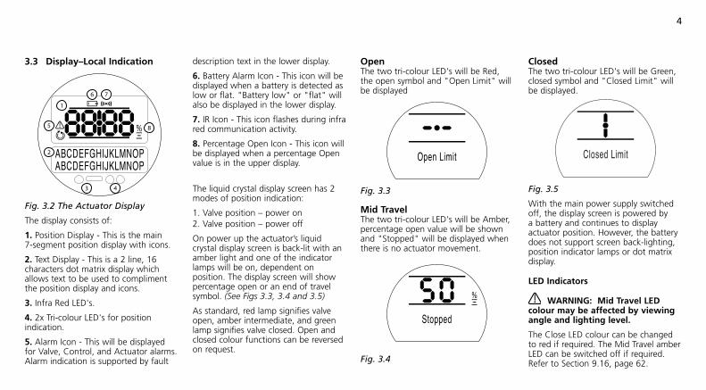
3.3 Display–Local Indication
Fig. 3.2 The Actuator Display
The display consists of:
1. Position Display - This is the main 7-segment position display with icons.
2. Text Display - This is a 2 line, 16 characters dot matrix display which allows text to be used to compliment the position display and icons.
3. Infra Red LED's.
4. 2x Tri-colour LED's for position indication.
5. Alarm Icon - This will be displayed for Valve, Control, and Actuator alarms. Alarm indication is supported by fault
description text in the lower display.
6. Battery Alarm Icon - This icon will be displayed when a battery is detected as low or flat. "Battery low" or "flat" will also be displayed in the lower display.
7. IR Icon - This icon flashes during infra red communication activity.
8. Percentage Open Icon - This icon will be displayed when a percentage Open value is in the upper display.
The liquid crystal display screen has 2 modes of position indication:
1. Valve position – power on2. Valve position – power off
On power up the actuator’s liquid crystal display screen is back-lit with an amber light and one of the indicator lamps will be on, dependent on position. The display screen will show percentage open or an end of travel symbol. (See Figs 3.3, 3.4 and 3.5)
As standard, red lamp signifies valve open, amber intermediate, and green lamp signifies valve closed. Open and closed colour functions can be reversed on request.
OpenThe two tri-colour LED's will be Red, the open symbol and "Open Limit" will be displayed
Fig. 3.3
Mid TravelThe two tri-colour LED's will be Amber, percentage open value will be shown and "Stopped" will be displayed when there is no actuator movement.
Fig. 3.4
ClosedThe two tri-colour LED's will be Green, closed symbol and "Closed Limit" will be displayed.
Fig. 3.5
With the main power supply switched off, the display screen is powered by a battery and continues to display actuator position. However, the battery does not support screen back-lighting, position indicator lamps or dot matrix display.
LED Indicators
WARNING: Mid Travel LED colour may be affected by viewing angle and lighting level.
The Close LED colour can be changed to red if required. The Mid Travel amber LED can be switched off if required. Refer to Section 9.16, page 62.
Open Limit
Closed Limit
Stopped

5
3.4 Display Status Indication – Travel
The IQ display provides real time status indication. The top line of the text display is reserved for travel status indication. Fig 3.6 shows the travel status example Closed Limit.
Fig. 3.6
Available travel status conditions displayed:
• Closed Limit Actuator has reached the set closed limit position.
• Open Limit Actuator has reached the set open limit position.
• Moving Open Actuator is traveling in the open direction.
• Moving Closed Actuator is traveling in the closed direction.
• Stopped Actuator has stopped in a mid travel position, indicated in the top display (%open).
• Timer Active Interrupter Timer option enabled only. Interrupter Timer has stopped the actuator mid travel for a period equal to the set Timer Off time. Refer to 9.13 page 59.
3.5 Display Status Indication – ControlThe bottom line of the text display is reserved for control status indication and is displayed for approximately 2 seconds after the control mode or signal is applied. Fig 3.7 shows the control status example Remote Control.
Fig. 3.7
Available control status conditions displayed:
• Local Control Local control selected - red selector.
• Local Stop Local stop selected – red selector.
• Remote Control Remote control selected – red selector.
• Local Close Local close signal applied – black selector.
• Local Open Local open signal applied – black selector.
• Remote Close Remote close (hardwired or analogue) signal applied.
• Remote Open Remote open (hardwired or analogue) signal applied.
• Remote ESD Remote hardwired emergency shut down signal applied.
• Remote Bus Open Remote Bus * open signal applied.
• Remote Bus Close Remote Bus* signal applied.
• Remote Bus ESD Remote Bus* emergency shut down signal applied.
* Bus Control option fitted may be Pakscan, Profibus, Modbus, DeviceNet or Foundation Fieldbus. Refer to actuator wiring diagram.
3.6 Display Alarm Indication
The IQ display provides alarm indication in the form of text and alarm icons.
There are 2 alarm icons:
General Alarm:
Battery Alarm:
General AlarmThe general alarm icon will be supported with text in the bottom line indicating the particular alarm, or if more than one is present, each alarm will be displayed in sequence.
Fig 3.8 shows the status example TORQUE TRIP CL.
Fig. 3.8
Closed Limit
Closed LimitRemote Control
StoppedTORQUE TRIP CL

6
Available alarm conditions displayed:
Valve Alarms
• TORQUE TRIP CL tripped off on torque while moving in the close direction.
• TORQUE TRIP OP tripped off on torque while moving in the open direction.
• MOTOR STALLED no movement detected after a signal to move. Control Alarms
• ESD ACTIVE ESD signal applied. When present the ESD signal overrides all local and remote control signals. Once the ESD action is carried out operation is inhibited while the ESD signal is maintained. Refer to 9.3 ESD Action page 36.
• INTERLOCK ACTIVE Open and/or close interlocks are configured on and are active. Refer to 9.3 Interlockpage 38. Operation in the direction of an active interlock(s) is inhibited. Note that when conditional control is configured, an active interlock will not inhibit local control operation.
Actuator Alarms
• THERMOSTAT TRIP Motor thermostat has tripped due to the motor overheating. Operation is inhibited until the thermostat resets automatically when the motor cools. Check actuator duty cycle against process requirements (running time, torque, ambient temperature).
• PHASE LOST (3-phase models only). The phase supply the actuator connected to terminal 3 is lost. Operation is inhibited.
• 24V LOST The 24 volt customer supply (terminals 4 & 5) has tripped. Check remote control wiring. Supply is protected with a resettable fuse.
• LOCAL CONTROL FAIL Check operation of control selectors (black and red).
• CONFIG ERROR There may be an error in the configuration (set up) of the actuator. Check and reset basic setting and check configuration settings.
• POS SENSOR FAIL Detected failure in the position sensing system – contact Rotork.
• TORQ SENSOR FAIL Detected failure in the torque sensing system – contact Rotork.
• EEPROM MISSING Contact Rotork
Battery Alarm
Fig. 3.7
The actuator checks the battery level at approximately 1 hour intervals. The battery alarm icon is displayed when the actuator detects its battery as being low and the display will indicate BATTERY LOW.
If the battery is flat or missing the display will indicate BATTERY FLAT.
When a low or flat battery alarm is displayed the battery should be replaced immediately. It is essential that the correct battery type is fitted to maintain actuator certification. Refer to page 65.
After replacing a battery the alarm icon will continue to be displayed until the next check and may take up to 1 hour. Cycling the power will force a battery check and clear the alarm.
PWR LOSS INHIBIT
If, on power up, the actuator detects a discharged battery and actuator power loss inhibit feature [OS] is enabled (refer to page 61), both battery and general alarm icons will be displayed and the bottom line will indicate alternately PWR LOSS INHIBIT and BATTERY FLAT. Electrical operation will be inhibited. The battery must be replaced and the limits must be reset. Refer to Section 10, page 66 and Section 8, page 29.
Open Limit BATTERY LOW

7
4.1 IQ10 to IQ35 Thrust Base Types A and Z
Removal of Drive Bush for Machining
Fig. 4 Bronze Drive Bush Fitted into Thrust Taking Base
Turn actuator onto its side, remove the two cap-headed screws holding base plate onto thrust base, pull out the drive bush complete with its bearing assembly.
Before machining the drive bush the thrust bearing must be removed. IQ10, IQ12 and IQ18 actuators have a sealed thrust bearing located on the drive bush and retained by the steel
Fig. 4.1 Components of Type A Thrust Base
bearing stop ring. The bearing stop ring is locked with one socket set screw.
IQ20, IQ25 and IQ35 have a thrust race ball bearing within the steel bearing housing, located on the drive bush and retained by the steel bearing stop ring. The bearing is sealed within its housing by O-rings located on the drive bush and on the bearing stop ring. The bearing stop ring is locked with two socket set screws.
1. Locate and loosen the locking socket set screw(s) in the bearing stop ring.
2. Unscrew the bearing stop from the drive bush. Slide the bearing off the drive bush. Keep the drive bush and stop ring in a safe clean place.
3. For all sizes ensure the drive bush male thread (stop ring) is not damaged during machining. For sizes IQ20, IQ25 & IQ35, ensure the O-ring located in the drive bush is not damaged during machining. Machine drive bush to suit the valve stem, allowing generous clearance on the screw thread for rising stem valves.
Re-assembly1. Remove all swarf from the drive bush, ensuring the O rings on the drive bush and bearing stop ring (where fitted) are undamaged, clean and greased.
2. Slide the bearing assembly onto the drive bush and ensure it is fitted down to the drive bush shoulder.
3. Screw the stop ring with the locking socket set screw(s) uppermost on to the drive bush until it comes to a stop – hand tight and lock with the locking socket set screws. The locking socket set screws must be done up tight to prevent the
assembly working loose, as shown in Fig 4.2. Refer to the table below for required tightening torques.
Fig. 4.2
4. Refit the drive bush assembly into the base casting on the actuator, ensuring that the slots in the drive bush are located into the drive dogs of the hollow output shaft.
5. Refit the base plate and secure with cap-headed screws.
Preparing Drive Bush4
Socket set Allen key Torque Torque screw size bit size Nm lbs/ft
M4 M2 2.2 1.62
M6 M3 7.8 5.75

8
4.2 IQ10 to IQ35 Non-Thrust Base Type B
Undo the four set screws securing the base plate to the gearcase and remove the base plate.
The drive bush and its retaining clip can now be seen.
Types B3 and B4 removal:(refer to Fig. 4.3)
Using external circlip pliers, expand the circlip while pulling on the drive bush. The drive bush will detach from the actuator centre column with the circlip retained in its groove.
Fig. 4.3
Fig. 4.4
Type B1(Refer to Fig. 4.4) The procedure for removal and refitting of the B1 drive bush is the and same as for B3 and B4, However the circlip is replaced with a custom spring clip. The spring clip operates in the same manner as the B3/B4 circlip but is expanded using long-nose pliers.
4.3 IQ40 to IQ95 Thrust Base Types A and Z
Removal of Drive Bush for MachiningEngage “hand” and turn handwheel until retainer set screw is visible through hole in actuator base.
Fig. 4.5 Locating Set Screw
Loosen set screw and unscrew retainer using hammer and punch. Remove drive bush and machine to suit valve stem or gearbox input shaft.
Allow generous clearance on screw thread for rising stem valves.
Fig. 4.6 Removal of Retainer
Fig. 4.7 Type A Drive Bush
If the actuator has a type A drive bush (Fig. 4.7) this can be fitted in position 1 or 2 to suit the position of the valve mounting flange.
Fig. 4.8 Type A Drive Bush in Position 1

9
Fig. 4.9 Type A Drive Bush in Position 2
If the actuator has a type Z3 drive bush (Fig. 4.10) this can only be fitted below the actuator base (Fig. 4.11).
Fig. 4.10 Type Z3 Drive Bush
Fig. 4.11 Type Z3 Drive Bush in Position 3
Re-Assembly Having confirmed the position required, insert the machined drive bush ensuring that the actuator output shaft dogs are in full engagement with the bush. Fit drive bush retainer securely, turning clockwise until fully tightened using hammer and punch. Rotate by hand wheel to align retainer set screw with hole in the side of base and tighten to 18.6 Nm / 13.7 lbsft.
4.4 IQ40 to IQ95 Non-Thrust Base Type B
Type B1 Output shaft bored and keyed to ISO 5210 standard. There is no drive bush to machine.
Fig. 4.12 Tightening Retainer Set Screw
Types B3 and B4 Identical drive bushes secured by cap headed screws.
B3 is supplied pre-machined to ISO 5210 standard.
B4 is supplied blank and must be machined to suit the input shaft of the gearbox or valve that it will drive.
Fig. 4.13 B3/B4 Drive Bush
Fig. 4.14 B3/B4 Drive Bush in Situ

10
Refer to Weights and Measures page 78 for actuator weight.
Ensure the valve is secure before fitting the actuator as the combination may be top heavy and therefore unstable.
If it is necessary to lift the actuator using mechanical lifting equipment certified slings should be attached as indicated in Fig.5 for vertical valve shafts and Fig.5.1 for horizontal shafts.
At all times trained and experienced personnel should ensure safe lifting, particularly when mounting actuators.
WARNING: The actuator should be fully supported until full valve shaft engagement is achieved and the actuator is secured to the valve flange.
A suitable mounting flange conforming to ISO 5210 or USA Standard MSS SP101 must be fitted to the valve.
Actuator to valve fixing must conform to Material Specification ISO Class 8.8, yield strength 628 N/sq mm.
WARNING: Do not lift the actuator and valve combination via the actuator. Always lift the valve/actuator assembly via the valve.
Each assembly must be assessed on an individual basis for safe lifting.
Fig. 5
Fig. 5.1
Mounting the Actuator5

11
5.1 Rising Stem Valves – Top Mounting
a) Fitting the Actuator and Base-as a Combined Unit – All Actuator Sizes
Fig. 5.2
Fit the machined drive bush into the thrust base as previously described, lower the actuator onto the threaded valve stem, engage “hand” and wind the handwheel in the opening direction to engage the drive bush onto the stem. Continue winding until the actuator is firmly down on the valve flange. Wind two further turns, fit securing bolts and tighten fully.
b) Fitting Thrust Base to Valve – Actuator Sizes 10 to 35 onlyFit the machined drive bush into the thrust base as previously described. Remove the thrust base from the actuator, place it on the threaded valve stem with the slotted end of the drive bush uppermost and turn it in the opening direction to engage the thread. Continue turning until the base is positioned onto the valve flange. Fit securing bolts but do not tighten at this stage. Lower the actuator onto the thrust base and rotate the complete actuator until the drive dogs on the actuator output shaft engage into the drive bush. Actuator flange should now be flush with base flange.
Fig. 5.3
Continue to turn actuator until fixing holes align. Using bolts supplied fix actuator to thrust base and tighten down to the required torque, see table A. Open valve by two turns and firmly tighten down fixings onto valve flange to the required torque, see table B.
Table A Table B
Torque
Size Nm lbs/ft
M8 Hex Head 14.8 10.9
M12 Hex Head 50.2 37.1
Torque
Imperial Size Nm lbs/ft
1/4 Hex 12.1 9
5/16 Hex 24.3 17.9
3/8 Hex 42.3 31.2
7/16 Hex 67 49.4
1/2 Hex 103.2 76.1
9/16 Hex 147.4 108.7
5/8 Hex 205.3 151.4
3/4 Hex 363.6 268.1
7/8 Hex 585 431.5
1 Hex 877.3 647.1
Torque
Metric Size Nm lbs/ft
M5-Hex 6.2 4.6
M6-Hex 10.8 7.9
M8-Hex 26.1 19.3
M10-Hex 51.6 38
M12-Hex 89.2 65.8
M16-Hex 219.8 162.1
M20-Hex 430.5 317.5
M24-Hex 736.8 543.4

12
5.2 Valve with Gearbox – Side MountingCheck that the mounting flange is at right angles to the input shaft, and that the drive bush fits the shaft and key with adequate axial engagement. Engage “hand”, offer up actuator to the input shaft and turn handwheel to align keyway and key. Tighten mounting bolts.
5.3 Non-Rising Stem Valves – Top MountingTreat as for side mounting except that when thrust is taken in the actuator, a thrust nut must be fitted above the drive bush and securely tightened.
5.4 Handwheel SealingEnsure that sealing plug in centre of handwheel (or spindle cover tube depending on which is fitted) is sealed with PTFE tape and fully tightened, ensuring that moisture does not pass down the centre column of the actuator.
5.5 IQM Modulating ActuatorsThe IQM range of actuators are suitable for modulating control duty of up to 1200 starts per hour in accordance with IEC 34-1 to S4 50%.
IQM actuators have a dynamic braking facility as standard. If mechanical overrun of the actuator and valve prove to be excessive for accurate control, the brake can be enabled by fitting a link to the actuator terminal block as indicated by the wiring diagram. With dynamic braking enabled, motor heating effects increase and therefore the number of actuator starts should be reduced to prevent motor thermostat tripping (refer to publication E410E for more information).
Commissioning of IQM range actuators is identical to the standard IQ (refer to Sections 7, 8 and 9 commencing on page 16).
5.6 IQML Linear Drive UnitConsists of a lead screw assembly arrangement attached to the base of the actuator in order to provide a linear output stroke between 8mm (3/8 in) minimum and 120mm (43/4 in) maximum.
The IQML can be supplied with or without a yoke mounting adaptor. This adaptor consists of four pillars and a base flange to suit the valve.
Fig. 5.4 IQML with Yoke
Fig. 5.5 IQML without Yoke

13
5.7 IQML Adjusting Linear StrokeWith actuator securely fitted to valve, but with the linear drive disconnected, ensure valve is at its fully closed (down) position.
Remove cover tube from actuator handwheel, locate the down stop adjustment on the linear drive unit and with two spanners loosen the lock nut, run the lock nut and tubular down stop to the end of the thread.
Fig. 5.6 Down Stop two Spanners
Turn the actuator handwheel clockwise, linear drive will move down towards the valve spindle, couple linear drive to valve spindle.
Turn the tubular down stop clockwise into the actuator until it comes to a mechanical stop. If the valve must close onto its seat by “TORQUE ACTION” then back off (anti-clockwise) the down stop by one third of one turn (equivalent to 1mm). Run the lock nut down ontothe tubular down stop and tighten with two spanners. There is no “up stop” (open) on the linear drive unit, the mechanical stop in the valve will give this position. Refit the top cover tube to the handwheel using PTFE tape to seal the thread.
The linear drive unit is pre-packed with grease type Rocol MTS 1000, use this or an equivalent high temperature-bearing grease.
A grease nipple is situated in the base of the actuator to enable lubrication of the lead screw. Periodically, depending on usage and temperature, apply two pumps of a grease gun.

14
WARNING:
Ensure all power supplies are isolated before removing actuator covers.
Check that the supply voltage agrees with that stamped on actuator nameplate.
A switch or circuit breaker must be included in the wiring installation of the actuator. The switch or circuit breaker shall be mounted as close to the actuator as possible and shall be marked to indicate that it is the disconnecting device for that particular actuator. The actuator must be protected with overcurrent protection devices rated in accordance with Rotork publication No. E130E Electric motor performance data for IQ range actuators.
WARNING:
Actuators for use on phase to phase voltages greater than 600V a.c. must not be used on supply systems such as floating, or earth-phase systems, where phase to earth voltages in excess of 600V a.c. could exist.
6.1 Earth/Ground ConnectionsA lug with a 6mm diameter hole is cast adjacent to the conduit entries for attachment of an external protective earthing strap by a nut and bolt. An internal earth terminal is also provided, however it must not be used alone as the protective Earth Connection.
6.2 Removing Terminal CoverUsing a 6mm Allen key loosen the four captive screws evenly. Do not attempt to lever off the cover with a screwdriver as this will damage the “O” ring seal and may damage the flamepath on a certified unit.
Fig. 6
Actuators containing a Setting Tool or Setting Tool Pro fitted to the inside of the terminal compartment cover are identified with a self-adhesive yellow label on the outside of the terminal compartment cover.
The wiring code card fixed in the cover is particular to each actuator and must not be interchanged with any other actuator. If in doubt check the serial number on the code card with that of the actuator.
A plastic bag in the terminal compartment contains: • Terminal screws and washers. • Spare cover “O” ring seal. • Wiring diagram. • Instruction book.
Fig. 6.1 - Actuator containing Rotork Setting Tool.
Fig. 6.2 - Actuator containing Rotork Setting Tool Pro.
Fig. 6.3
6.3 Cable EntryOnly appropriate certified Explosion-Proof entry reducers, glands or conduit may be used in hazardous locations.
Cable Connections6

15
Remove red plastic transit plugs. Make cable entries appropriate to the cable type and size. Ensure that threaded adaptors, cable glands or conduit are tight and fully waterproof. Seal unused cable entries with a steel or brass threaded plug. In hazardous areas an appropriately certified threaded blanking plug must be used.
6.4 Connecting to Terminals
On EExde enclosure units connections to the power and control terminals must be made using AMP type 160292 ring tabs for power and earth terminals and AMP type 34148 ring tabs for the control terminals.
Refer to the wiring diagram inside the terminal cover to identify functions of terminals. Check that supply voltage is the same as that marked on the actuator nameplate.
Remove power terminal screen.
Begin by connecting these cables and replace screen.
When all connections are made ensure wiring diagram is replaced in the terminal compartment.
6.5 Replacing Terminal Cover
Ensure cover “O” ring seal and spigot joint are in good condition and lightly greased before re-fitting cover.
Heading
ATTENTION: RED PLASTIC PLUGS IN CONDUIT ENTRIES ARE FOR TRANSIT ONLY.FOR LONG TERM PROTECTION FIT SUITABLE METAL PLUGS.
ATTENZIONE: I TAPPI IN PLASTICA ROSSA PER L'ENTRATA CAVI SONO SOLOTEMPORANEI. PER UNA PROTEZIONE PERMANENTE PREGO SOSTITUIRLI CON
APPOSITI TAPPI METALLICI.
ATENCION: LOS TAPONES ROJOS DE PLASTICO EN LAS ENTRADAS DE CABLESON UNICAMENTE PARA TRANSPORTE. PARA PROTECCION PERMANENTE
COLOCAR TAPONES METALICOS APROPIADOS.
ACHTUNG: DIE ROTEN PLASTIKSTOPFEN SIND NUR FÜR DEN TRANSPORT GEEIGNET. FÜR DAVERHAFTEN SCHUTZ SIND DIESE GEGEN GEEIGNETE
BLINDSTOPFEN AUSZÜTAUSCHEN.
ATTENTION: LES BOUCHONS PLASTIQUES ASSURENT UNE PROTECTIONTEMPORAIRE. POUR UNE PROTECTION DEFINITIVE UTILISER DES BOUCHONS
METALLIQUES.

16
7.1 The Setting ProcedureThe Rotork IQ range of actuators is the first that enables commissioning to be carried out without removing covers.
Setting torque, limit and other functions is achieved by using the Infra-Red Setting Tool. The Setting Tool is certified Intrinsically Safe to allow commissioning in hazardous areas.
All the commissioning functions are stored in non-volatile memory in the actuator. The Setting Tool enables the user to view all the functions in turn via the actuator display window. As each function is viewed its setting can be checked and, if required, changed within the bounds of that function.
Commissioning may be carried out with main power switched on or off. Refer to page 22 for Power Off Setting.
The setting procedure is divided into two stages:
1. Basic Settings Settings for end of travel limit actions, torque values, limit positions etc.
2. Configuration Settings Settings covering the control, indication and optional equipment functions.
All IQ actuator functions are configured before dispatch to Rotork standard default settings unless alternatives have been specified with the order. Should difficulty be encountered during commissioning the default settings can be reinstated, returning the actuator configuration to its original manufactured state. Site commissioning can then begin again (refer to Section 9.18 page 63).
The default function should be used with caution as settings selected after manufacture may be essential for the safe operation of the valve and/or plant.
Actuator Display
Commissioning7
Position Display 50 This may be an open or closed symbol or a percentage open value. m Torque and Position 50 Refer to Section 10.
m Password P? k PC k Ir k tP
m Crossroad cr k m
Basic Settings Configuration Settings Direction Indication Contacts Limit Actions Control Mode Torque Values Options Limit Positions Help Screens Defaults
Note: The Basic Settings must be commissioned first.
Torque

17
7.2 The Setting Tool (old version)
SpecificationEnclosure IP67
Certification EEx ia IIC T4 (intrinsically safe) FM, INT SAFE, Class I & II Div 1 Groups A B C D E F G, T4A CSA, Exia, Class I, II Div 1 Groups A B C D
Power supply 9V Battery (supplied and fitted)
Operating range 0.75m (from actuator display window)
Name Instruction1. m Key* Display next function down
2. k Key* Display next function across
3. - Key Decrease/change displayed function’s value or option setting
4. + Key Increase/change displayed function’s value or option setting
5. Key Enter displayed value or option setting
* Pressing the two arrow keys together returns the actuator display to the position indication mode
Infra-red local operation (when enabled)
5. Key Stop actuator
6. Key Open actuator
7. Key Close actuator
8. Infra-red Transmitter Window
Fig. 7.1 The Setting Tool
Setting Tool Battery ReplacementBattery status can be checked by looking at the Infra-red transmitter window while depressing any Setting Tool button. A flashing red indicator should be seen.
Battery replacement must be carried out in a safe area. To replace the battery remove the six caphead screws in the back of the Setting Tool. Remove the back cover to expose the battery.
In order to maintain hazardous area certification fit only Duracell MN1604 or Rayovac Alkaline Maximum NoAL-9V battery types. Refit cover ensuring red indicator LED faces the transmitter window in the back cover.
When a button is depressed the Setting Tool transmits the relevant instruction to the actuator by infra-red pulses and must therefore be directly in front of the actuator indicator window and at a distance no greater than 0.75m.
8 24
6
75
31

18
Commissioning continued7
7.2 The Setting Tool Pro (new version)
SpecificationEnclosure IP54
Manufacture This Setting Tool Pro has been constructed in accordance with: EEx ia IIC T4 (intrinsically safe) FM, INT SAFE, Class I & II Div 1 Groups A B C D E F G, T4 CSA, Exia, Class I Div 1 Groups A B C D
Power supply 2x 1.5V Batteries (supplied and fitted)
Operating range 0.75m (from actuator display window)
Name Instruction1. m Key* Display next function down
2. i Key Display previous function up
3. k Key* Display next function across
4. o Key Display previous function across
5. - Key Decrease/change displayed function’s value or option setting
6. + Key Increase/change displayed function’s value or option setting
7. m Key Initiate download/upload mode
8. Key Enter displayed value or option setting
* Pressing these two arrow keys together returns the actuator display to the position indication mode
Infra-red local operation (when enabled)
9. Key Stop actuator
10. Key Open actuator
11. Key Close actuator
12. Infra-red Transmitter Window
Fig. 7.2 The Setting Tool Pro
8
2
7
6
11
5
3
1
4
10
12

19
Download / Upload FunctionThis new feature has been introduced with the new Rotork Setting Tool Pro. It allows the user to download datalogger files and download/upload configuration files. The new tool is weatherproof and intrinsically safe and so it can be used safely in all environments. For more information refer to Section 10.1, page 68.
Setting Tool Pro Battery ReplacementBattery status can be checked by looking at the Infra-red transmitter window while depressing any Setting Tool Pro button except the download button. A flashing red indicator should be seen.
Battery replacement must be carried out in a safe area. To replace the battery remove the six cap head screws in the back of the Setting Tool Pro. Remove the back cover to expose the battery.
In order to maintain hazardous area certification fit only Duracell MN1500 or GP Batteries GP15A battery types. Refit cover ensuring red indicator LED faces the transmitter window in the back cover.
When a button is depressed the Setting Tool Pro transmits the relevant instruction to the actuator by infra-red pulses and must therefore be directly in front of the actuator indicator window and at a distance no greater than 0.75m.
Display Set-Up ModeThe Setting Tool and Setting Tool Pro arrow keys are used to access and navigate through the actuator set-up procedure using the actuator display. Each actuator function with it's current setting is represented on screen by a combination of code and text. The Setting Tool change keys (+ and –) allow the user to view the available setting options.
The examples of displayed functions Close Action, [C2] and Open Torque, [tO] are shown above. Note that a setting option or value is highlighted.
This instruction manual uses both code and text for description.
Close ActionClose on Torque
Open Torque40%
FunctionCode
Function
SettingCode
SettingOption
FunctionCode
Function
SettingValue
SettingValue

20
7.3 Entering the Actuator Setting ProcedureWith the actuator securely mounted on the valve, the mains supply on and Local control or Stop selected.
PRESS THE m KEY.
The actuator upper display will remain the same and the lower display will change to Torque value. This will be represented by Torque = XX% and a bar graph. (For instantaneous torque & position monitoring, refer to Section 10, page 66.)
PRESS THE m KEY.
The actuator display will change and the password protection display will be seen.
The Actuator Function Settingscan be protected by the Use
of a Password
7.4 Setting Mode – PasswordTo enable setting and adjustment of the actuator functions the correct password must be entered. The factory set (default) password is [ld]. If the actuator has previously been set with a site password this must be entered.
Use the + or - keys to scroll through the available passwords 00–FF (hexadecimal). With the correct password displayed press the enter key.
PRESS THE KEY.
Two “setting” bars will appear and will remain visible on every function display screen. In addition, "Password Correct" will be displayed for 3 seconds.
Default Password,Setting Mode Enabled
7.5 New Password [PC]To configure a new password, the actuator must be in setting mode with the password display – setting mode enabled – showing,
PRESS THE k KEY.
The display will change to [PC]. Using the + or - key scroll through the available passwords until the desired password is displayed.
PRESS THE KEY.
Password Changed to [IE]
NOTE: The new password becomes effective the next time setting mode is entered.
7.6 Checking ModeThe actuator function settings can be checked without entering the correct password. The settings can only be viewed and not altered. The setting bars will not be seen.
Password Display, Checking Mode
Once the procedure has been completed in the required mode
PRESS THE m KEY.
The procedure branch [Cr] (crossroad) display can now be seen (refer to Section 7.7 page 21).
Commissioning continued7
Enter PasswordID Hex
Password CorrectEnter Password
Change PasswordIE Hex
Enter PasswordID Hex

21
7.7 Crossroad [Cr]
To access the Basic Settings press the arrow m key (refer to Section 8 Commissioning Basic Settings page 22).
To access the Configuration Settings press the arrow k key (refer to Section 9 Commissioning Configuration Settings page 31).
7.8 The Actuator Display – Setting/Checking ModeActuator functions as laid out in the Basic and Configuration commissioning stages, can be individually displayed by using the Setting Tool arrow keys.
The m arrow key will always display the FIRST function on the next level DOWN within the procedure.
The k arrow key will always display the NEXT function on the SAME level and will wrap around the functions on the same level.
The actuator display indicator lamps will continue to indicate valve position but will also flash during IR communication.
Actuator functions are displayed in code form in the top left portion of the liquid crystal display screen.
The setting for the displayed function is shown in the top right hand portion of the screen. Depending on the actuator function displayed, its setting may be an option or a value.
Text relating to the function and setting values will be displayed in the lower display.
In setting mode the Setting Tool + or - keys will cause the setting to be changed. In checking mode the settings cannot be altered.
In setting mode, once displayed, a new setting can be entered into the actuator memory by pressing the key. The setting will flash off and back on, confirming its selection, and "Stored" will be displayed for 2 seconds in the text display.
TOP LEFT PORTION Function e.g.
tC = Torque Close
TOP RIGHT PORTIONFunction Settinge.g. Value = 40%
LOWER DISPLAY Function: Close Torque Setting Value: 40%
Typical Actuator Function DisplaySetting Mode Enabled
7.9 Returning to Valve Position DisplayThere are five ways of returning to valve position display:
1. Approximately 5 minutes after the last Setting Tool operation the display will automatically return to position display.
2. Press the m and k arrow keys together.
3. Press the m arrow key until the display returns to position.
4. Select Remote control using the red Local/Stop/Remote selector.
5. If you have the new Setting Tool Pro then you can use the iarrow key to return to position display.
Basic SetupConfig Setup
Close Torque40%

22
Fig. 8
ELECTRICAL OPERATION MUST NOT TAKE PLACE UNTIL THE BASIC SETTINGS HAVE BEEN MADE AND CHECKED.
The actuator’s Basic Settings affect the correct operation of the valve by the actuator. If the actuator has been supplied with the valve, the valve maker or supplier may have already made these settings.
This instruction assumes setting mode has been entered (refer to section 7.4 page 20).
Viewing the Basic SettingsWith the actuator mounted on the valve, the power supply on and Local or Stop control selected, point the Setting Tool at the actuator indicator window from a distance of no more than 0.75m. By pressing the m key and, when appropriate, the k key, it is possible to move through the procedure, displaying the various functions and their settings as shown in Fig. 8.1 (refer to page 23).The right-hand side of Fig.8.1 explains the function of each LCD display.
Power Off SettingIQ allows settings to be viewed and set without main power. To enable this function, engage handwheel drive and rotate until the output drive moves (refer to page 3). The Setting Tool can now be used. As long as a Setting Tool key press takes place within the 30 seconds timeout period, Power Off Setting will remain enabled. If no infra-red Setting Tool communication takes place the display will return to indicating position. The actuator must then be operated by handwheel to re-enable Power Off Setting.
Settings and operation must be verified by electric operation and function test of the actuator to ensure correct operation.
8 Commissioning –Basic Functions

23
Torque
Viewing the Basic Settings
Function Description
Position Display 50 (This may be an open or closed symbol or a % open value.) m m 50 Torque and Position Display
m mP? k PC k Ir k tP Password k Password Change k IrDA k Torque Reference Profile
m mCr k Configuration Crossroad k Configuration Settings, refer to page 32.
C1 k C2 k C3 Direction to Close k Close Action k Open Action
m mtC k tO Torque Value Closing k Torque Value Opening
m mLC k LO Limit Closed k Limit Open
m m 50 Position Display
Fig. 8.1 Basic Setting Displays
BASIC SETTINGS CONTENTS page
C1 Direction to Close 22C2 Close Action 23C3 Open Action 24tC Torque Value Closing 25tO Torque Value Opening 26LC Set Limit Closed 27LO Set Limit Open 27
REFER TO SECTION 7, COMMISSIONING

24
The actuator can be configured to be clockwise or anti-clockwise to close. Manually operate actuator and valve to establish correct closing direction. Conversion Handwheel direction labels are available.
50
m 50
mP? k PC k Ir k tP
mcr
m c1 k c2 k c3
mtC k tO
mLC k LO
m 50
Using the + or - key, display the character conforming to correct closing direction.
[C] in the Setting Field Indicating Clockwise to Close
[A] in the Setting Field Indicating Anti-clockwise to Close
Having ensured that the display corresponds to the established closing direction
PRESS THE KEY.
The displayed option will flash (stored), indicating that it has been set.
PRESS THE k KEY.
Direction to CloseC1
Close DirectionClockwise
Close DirectionAnticlockwise
Torque

25
The actuator can be configured to close on torque for seating valves and limit for non-seating valves.
50
m50
mP? k PC k Ir k tP
mcr
m c1 k c2 k c3
mtC k tO
mLC k LO
m50
Refer to valve manufacturer for recommended setting.
In the absence of valvemaker instructions refer to the following table
Valve type Close Open
Wedge gate “torque” “limit” Globe “torque” “limit”
Butterfly “limit” “limit” Thru conduit “limit” “limit” Ball “limit” “limit” Plug “limit” “limit” Sluice gate “limit” “limit” Penstock “limit” “limit” Parallel slide “limit” “limit”
Using the + or - key, display the required option.
[CL] in the Setting Field Indicating Close on Limit - default setting.
[Ct] in the Setting Field Indicating Close on Torque.
Having selected the required option
PRESS THE KEY.
The displayed option will flash (stored), indicating that it has been set.
PRESS THE k KEY.
NOTE: When set to close on torque, the actuator will apply the level of torque as set for [tC] in seating the valve (refer to [tC] page 27).
Close ActionC2
Close ActionClose on Torque
Close ActionClose on Limit
Torque

26
The actuator can be configured to open on torque for back seating valves or limit for non back seating valves.
Refer to valve manufacturer for recommended setting. In the absence of valvemaker instructions set “Open Limit”.
50
m50
m P? k PC k Ir k tP
m cr
m c1 k c2 k c3
m tC k tO
m LC k LO
m50
Using the + or - key display the required option.
[OL] in the Setting Field Indicates Open on Limit - defualt setting.
[Ot] in the Setting Field Indicates Open on Torque.
PRESS THE KEY.
The displayed option will flash (stored), indicating that it has been set.
PRESS THE k KEY.
NOTE: When set to open on torque, the actuator will apply the level of torque as set for [tO] in back seating the valve (refer to [tO] page 28).
Open ActionC3
Open ActionOpen on Torque
Open ActionOpen on Limit
Torque

27
The value of torque available in the close direction can be configured.
Refer to valve manufacturer for recommended value.
The closing torque value can be varied between 40% and Rated (100%), in 1% increments.
50
m50
mP? k PC k Ir k tP
m cr
m c1 k c2 k c3
m tC k tO
mLC k LO
m50
Using the + and - keys, the display recommended value. In the absence of a recommended torque value, try a low setting and increase until satisfactory valve operation is achieved.
If the actuator fails to complete a closed valve operation due to the set torque being reached (Torque Trip CL Alarm, page 5) this may indicate a valve and/or process problem or change. It is the responsibility of the user to ensure the valve and process conditions are within specified operational limits before increasing the Set Close torque value.
PRESS THE KEY.
The displayed value will flash (stored), indicating that it has been set.
Should the set level of torque be developed in closing, the actuator will torque trip and stop.
PRESS THE k KEY.
NOTE: Rated torque is quoted on the actuator nameplate.
40% of Rated Torque
99% of Rated Torque
Rated Torque
Close TorquetC
Close Torque40%
Close Torque99%
Close Torque100%
Torque

28
The value of torque available in the open direction can be configured.
Refer to valve manufacturer for recommended value.
50
m50
m P? k PC k Ir k tP
m cr
m c1 k c2 k c3
m tC k tO
mLC k LO
m50
The opening torque value can be varied between 40% and Rated, in 1% increments. In addition “Boost” can be configured when no open torque protection is required.
BOOST SHOULD NOT BE SELECTED WHEN THE ACTUATOR HAS BEEN CONFIGURED TO OPEN ON TORQUE (refer to [C3] page 26) UNLESS BACK SEATING AT RATED TORQUE IS ACCEPTABLE.
Using the + and - keys, display the recommended torque value.
In the absence of a recommended torque value, try a low setting and increase until satisfactory valve operation is achieved.
If the actuator fails to complete a open valve operation due to the set torque being reached (Torque Trip OP Alarm, page 5) this may indicate a valve and/or process problem or change. It is the responsibility of the user to ensure the valve and process conditions are within specified operational limits before increasing the Set Open torque value.
NOTE: Rated torque is quoted on the actuator nameplate. Boost torque is at least 140% of Rated torque.
PRESS THE KEY.
The displayed value will flash (stored), indicating that it has been set.
Should the set level of torque be developed in opening, the actuator will torque trip and stop.
PRESS THE m KEY.
40%
99%
Rated
Boost
In checking mode, on pressing the m key after reviewing open torque setting, the display will revert to valve position.
Open TorquetO
Open Torque40%
Open Torque99%
Open Torque100%
Open TorqueBoost
Torque

29
NOTE: It is possible to set the Open Limit Position [LO] first.
50
m50
mP? k PC k Ir k tP
mcr
m c1 k c2 k c3
m tC k tO
m LC k LO
m50
NOTE: When in checking mode Set Limit Closed [LC] does not appear.
With [LC] displayed
Limit Closed
Move valve manually to the closed position. Allow for overrun by winding actuator output open by 1/2 to 1 turn.
PRESS THE KEY.
The two bars will flash (stored) and the closed indicator lamp will illuminate, indicating closed limit position has been set.
PRESS THE k KEY.
To check closed limit position hand wind valve open until the amber lamp illuminates. Wind valve back closed until the closed lamp illuminates.
50
m 50
m P? k PC k Ir k tP
m cr
m c1 k c2 k c3
m tC k tO
m LC k LO
m 50
NOTE: When in checking mode Set Limit Open [LO] does not appear.
With [LO] displayed
Limit Open
Move valve manually to the open position. Allow for overrun by winding actuator output closed by 1/2 to 1 turn.
PRESS THE KEY.
The two bars will flash (stored) and the open indicator lamp will illuminate, indicating open limit position has been set.
PRESS THE m KEY.
The open symbol (refer to Fig. 3.3. page 4) should now appear.
Set Limit ClosedLC Set Limit OpenLO
Set Close LimitMove to Close
Set Open LimitMove to Open
Torque
Torque

30
50
m 50
m P? k PC k Ir k tP
m cr
m c1 k c2 k c3
m tC k tO
m LC k LO
m 50
If the procedure has been followed as described, the positional display will indicate that the actuator is in the open position.
Select Remote control momentarily, using the red selector to exit setting procedure and then select required control: Local, Stop or Remote.
With the correct settings made electric operation can now be carried out safely.
Return toPositional Display
Torque

31
Fig. 9
The Configuration Settings can be configured to suit site control and indication requirements. It is important that Basic Settings such as limits and torque switch settings are set before work commences on commissioning the Configuration Settings (refer to page 22).
The layout of the Configuration Settings accessed with the Setting Tool are detailed in Fig. 9.1. To successfully commission the Configuration Settings, information about the site or process control system will be required.
The supplied actuator Wiring Diagram details control and indication devices fitted to the actuator along with terminal connection detail and standard remote control wiring systems.
Power Off SettingIQ allows settings to be viewed and set without mains power. To enable this function, engage handwheel drive and rotate until the output drive moves by one turn (refer to page 3).The Setting-Tool can now be used. As long as a Setting Tool key press takes place within the 30 seconds timeout period, Power Off Setting will remain enabled. If no infra-red Setting Tool communication takes place the display will return to indicating position. The actuator must then be operated by handwheel to re-enable Power Off Setting.
Settings and operation must be verified by electric operation and function test of the actuator to ensure correct operation.
9 Commissioning –Configuration Settings

32
Positional Display
m
m P? k PC k Ir k tP
m Contact Function Value Contact Form
cr k Contact S1 r1 k r1 k r1 m Contact S2 r2 k r2 k r2 m Contact S3 r3 k r3 k r3 m Contact S4 r4 k r4 k r4 m ESD ESD Thermostat ESD Overide ESD Override Maintained 2-wire External Conditional Torque Switch ESD Action Contact Type Bypass Interlocks Local Stop Local Control Control Interlocks Control Bypass Control Mode Configuration A1 k A2 k A3 k A4 k A5 k A6 k A7 k A8 k A9 k At
m Extra Indication 4-20mA Remote Interrupter Setting Tool Power Loss Choose Mid-Travel Contacts CPT Control Source Timer Local Control Inhibit LED Colour LED Language
Option Selection OE k OI k Od k OJ k Or k OS k OH k OU k UL
m Option Functions – If Analogue, Bus System or Interrupter Timer control options are fitted their appropriate set-up screens will be automatically inserted here.
m Software Option 1 Option 2 Service Version Version Version Reset Password
Service Mode Un k UI k U2 k Ur k UP
m Help Screens H1 k H2 k H3 k H4 k H5 k H6 k H7 k H8 k H9
m Default Option d1 k d2
m Return to Positional Display Fig. 9.1 Configuration Settings
IrDAcomms
PrimaryFunctions
m
Torque
50
Torque ReferenceProfile

33
Having established that the Basic Settings have been correctly set, the Configuration Settings can now be configured to suit site control and indication requirements.
It is possible to move through the various Configuration Settings as shown in Fig. 9.1 using the k and m keys.
The actuator wiring diagram will indicate any options fitted.
Options Setting Tool Local Control [Or] and Power Loss Inhibit [OS] are standard features, their use being optional.
In order to display the Configuration Settings it is necessary to press the m key until [Cr] appears.
If you have chosen to enter Configuration Settings in the checking mode the display will be as Fig. 9.2.
If you have chosen to enter Configuration Settings in the setting mode the display will be as Fig. 9.3 (refer to Section 7).
Fig. 9.2 Fig. 9.3
PRESS THE k KEY.
9.1
CONFIGURATION SETTINGS
page
9.1 Accessing the Configuration Settings 339.2 Indication Contacts S1, S2, S3 and S4 349.3 Control Mode Configuration 369.4 Option Extra Indication Contacts S5–S8 399.5 Option CPT (4-20mA Indication) 409.6 Option Folomatic (Analogue Position Control) 419.7 Remote Control Source 449.8 Bus System Option Pakscan 459.9 Bus System Option Modbus 489.10 Bus System Option Profibus DP 519.11 Bus System Option DeviceNet 549.12 Bus System Positioning Control Settings 579.13 Option Interrupter Timer 599.14 Setting Tool Local Control 619.15 Inhibit Operation After Power Loss 619.16 Indicator LEDs 629.17 Display Language 629.18 Default Options 6410.2 Help Screens 7110.3 IrDA Diagnostics and Configuration 76
Accessing theConfiguration Settings
Basic Setup Config Setup
Basic SetupConfig Setup

34
Indication contacts S1 [r1], S2 [r2], S3 [r3] and S4 [r4] may each be set to trip for any one of the following functions:
Code Function (as displayed)
[CL] Closed Limit [OP] Open Limit [Po] Position % Open [rr] Motor Running [dC] Closing [dO] Opening [d?] Moving [HA] Hand Operation [bL] Moving-Blinker [UA] Valve Alarm [tC] Torque Trip Close (direction)
[tO] Torque Trip Open (direction)
[tt] Torque Trip (any position)
[tl] Torque Trip Mid (travel)
[St] Motor Stalled [LS] Stop Selected [Lo] Local Selected [rE] Remote Selected [CA] Control Alarm [ES] ESD Active
[Ol] Open Interlock Active [Cl] Close Interlock [lL] Interlock Active [AA] Actuator Alarm [Ht] Thermostat Tripped [LP] Lost Phase *
[24] 24V Power Failure **
[bA] Battery Low [rP] Relay Parity
The S contact form can be set normally open [no] or normally closed [nc].
The procedures for setting up contacts S2, S3 and S4 are the same as those shown for S1.
Unless specified with order, the default settings for indication contacts are as follows:
S1 – [CL] Closed Limit [no]
S2 – [OP] Open Limit [no]
S3 – [CL] Closed Limit [nc]
S4 – [OP] Open Limit [nc]
* [LP] Function not available for phases 1 & 2, only for phase 3. For phase loss detection on phase 1 & 2 please use monitor relay
** [24] Function not available if the 3 phase supply is lost.
Using the + or - key display the desired function.
PRESS THE KEY.
The displayed function will flash indicating that it has been set.
Contact S1 Configured to Trip at Valve Closed Limit
PRESS THE k KEY.
Contact S1 - Functionr1 9.2 Indication ContactsS1, S2, S3 and S4
S1 FunctionClose Limit

35
This screen will only display if relay function is set to [P0] Position Open.
When the S contact function is set to [P0], the required intermediate position value must be set. No other contact function requires a value to be set.
The value can be set from 1% open to 99% open in 1% increments.
Using the + or - key, display the required value.
PRESS THE KEY.
The displayed value will flash (stored) indicating that it has been set.
Value Set to Indicate25% Open
PRESS THE k KEY.
Use the + or - keys to select between [nO] Normally Open and [nC] Normally Closed.
PRESS THE KEY.
The displayed option will flash (stored) indicating that it has been set.
Contact S1 Configured as a Normally Open Contact
NOTE: If function [PO] Position Open is selected and it is configured as a normally open contact it will make at the set value with the actuator moving in the open direction.
To access S2–S4
PRESS THE m KEY.
r1 Contact S1Contact Form
S1 ContactNormally Open
Contact S1 - Valuer1
S1 % Position25%

36
The Control Mode Configuration affects how the actuator will respond under conditions of emergency shut down, local control, remote control interlocks, and 2-wire remote control. Also included is an unseating torque switch bypass function. Unless specified with order, the control mode configuration will be set as shown for default configuration on page 63.
If it is necessary to change the configuration follow the instructions in this section.
There are 10 configurable control functions:
Code Function (as displayed)
[A1] ESD Action
[A2] ESD Contact Type [A3] ESD Override Stat [A4] ESD Override Interlocks [A5] ESD Override Local Stop [A6] Maintain Local Control [A7] 2-wire Remote Priority [A8] Interlocks [A9] Conditional Control [At] Torque Switch Bypass.
An active ESD signal applied to the actuator will override any existing or applied local or remote control signal. ESD can be configured to override the motor thermostat, active interlocks or local stop selection. Refer to A3, A4 and A5.
The default action under an active ESD signal is to stay put [SP] Stay Put.
Press the + or - key to select the required ESD action:
[OF] Off on ESD
[CL] Close on ESD
[SP] Stay Put on ESD
[OP] Open on ESD
PRESS THE KEY.
The displayed option will flash (stored) indicating that it has been set.
The default setting for ESD Contact Type is [nO] Normally Open.
For actuators set to ESD [nO] Normally Open the ESD Signal must be applied to activate the ESD command. For ESD [nC] Normally Closed the signal must be removed to activate the command. Press the + or - key to choose the contact type.
PRESS THE KEY.
The displayed option (stored) will flash indicating that it has been set.
Actuator Responds to a Normally Open ESD Contact (Signal Applied)
The default setting for ESD Override Thermostat is [OF] No during ESD. The thermostats remain in circuit and enabled during ESD.
The motor thermostats can be bypassed during ESD as a factory set, hard-wired option only. Contact Rotork for information.
Danger: Actuator hazardous area certification is invalidated while the thermostats are bypassed.
[A3] should be set to reflect the factory set configuration of thermostat bypass.
During an ESD event:
[A3] = [OF] No, thermostats enabled
[A3] = [On] Yes, thermostats bypassed
ESD ActionA1 ESD Contact TypeA2 A3Control ModeConfiguration
ESD Override Thermostat
ESD ActionClose
ESD Contact TypeNormally Open
ESD OverrideStat: No
9.3

37
The default setting for ESD Override Interlocks is [OF] No. ESD action will not override an active interlock applied to the actuator.
If an applied ESD signal is required to override active interlocks causing the ESD action as set for A1, press the + or - key. The display will change to [On] Yes.
PRESS THE KEY.
The displayed option will flash (stored) indicating that it has been set.
The default setting for ESD Override Local Stop is [OF] No. ESD will not override local stop when selected.
If an applied ESD signal is required to override local stop causing the ESD action as set for A1, press the + or - key. The display will change to [On] Yes.
PRESS THE KEY.
The displayed option will flash (stored) indicating that it has been set.
The default setting for Local Actuator Pushbutton control is self-maintained [On] Yes.
If non-maintained actuator pushbutton control is required (jogging, inching, push to run), press the + or - key. The display will change to [OF] No.
PRESS THE KEY.
The displayed option will flash (stored) indicating that it has been set.
The default setting for 2-wire Remote Priority is [SP] Stay Put. If an open and closed remote control signal are applied simultaneously the actuator will stay put (stop if running). Refer to actuator wiring diagram or publication E120E.
Use the + or - key to select the required priority:
[OP] Open
[SP] Stay Put
[CL] Close
PRESS THE KEY.
The displayed option will flash (stored) indicating that it has been set.
2-wire Control – Stay Put Priority
ESD OverrideInterlocks: No
ESD OverrideLocal Stop: No
Maintain LocalControl: Yes
2-Wire RemotePriority: Stay
A4 ESD OverrideInterlocks A5 ESD Override
Local Stop A6 MaintainLocal Control A7 2-wire Remote
Priority

38
Actuators are delivered with the interlock facility disabled [OF] Disabled. Refer to the actuator wiring diagram or publication E120E for interlock control circuits.
To enable remote external interlocks press the + or - key.
The display will change to [On] Enabled.
PRESS THE KEY.
The displayed option will flash (stored) indicating that it has been set.
Note: If interlocking is required in only one direction, it will be necessary to connect a link between the actuator terminals associated with the other direction. Refer to wiring diagram.
Where a high level of safety integrity is required, Conditional Control can be configured. In this mode two discreet signals are required for remote operation. Remote control will be conditional on both a control signal (open or close) and the appropriate interlock signal being applied simultaneously. Failure of either or a spurious signal will not cause operation.
Interlocks [A8] must be set [On] Enabled. Interlock signals are not required for local operation.
The default setting for conditional control is [OF] Disabled. To enable conditional control press the + or - key.The display will change to [On] Enabled.
PRESS THE KEY.
The displayed option will flash (stored) indicating that it has been set.
The default setting for Torque Switch Bypass is [OF] Off, the torque switches are not bypassed during the unseating movement.
To bypass the torque switches during the unseating movement press the + or - key.
The display will change to [On].
PRESS THE KEY.
The displayed option will flash (stored) indicating that it has been set.
The torque switches will be bypassed from closed limit to 5% open when opening and from open limit to 95% when closing. Bypassing the torque switches makes torque in excess of rated and up to actuator stall available for unseating a ‘‘sticky’’ valve. Outside these positions the torque setting will revert to the values set for [tC] Close Torque, see page 27 and [tO] Open Torque, page 28.
InterlocksA8 Conditional ControlA9 Torque Switch BypassAt
InterlocksDisabled
ConditionalControl: Disabled Torque Switch
Bypass: Off

39
Extra indication contacts S5 [r5], S6 [r6], S7 [r7] and S8 [r8] are available as an option.
Check actuator circuit diagram for inclusion.
When the Extra Contact Option is included the set-up procedure and available contact functions for S5 – S8 are identical to S1–S4 (refer to Section 9.2 page 34).
Unless specified with order the default setting for the extra indication contacts will be as follows:
S5 [r5] Close limit
S6 [r6] Open limit
S7 [r7] Torque trip mid
S8 [r8] Remote selected
NOTE: If the Extra Contact Option is not included in the actuator build, any settings made for S5–S8 will have no effect on the indication output of the actuator.
The action of turning on the Extra Contact Option makes an additional series of set-up screens available
Press the + or - key to select the Extra Contact Option set-up screens [On].
PRESS THE KEY.
The displayed option will flash (stored) indicating that it has been set.
PRESS THE m KEY TO ACCESS S5 TO S8 SET-UP DISPLAYS.
The procedure for setting S5 to S8 is the same as that for S1 to S4 (refer to Section 9.2 page 34).
Extra ContactsMenu: On
Extra ContactsMenu: Off
9.4 Option ExtraIndication Contacts OE Display Extra Contact
Set-up Screens

40
Setting instructions for actuators including a CPT providing 4-20mA analogue position feedback.
The CPT is an optional extra. It may be internally or externally powered.
Check wiring diagram for inclusion and connection details.
With [HI] Displayed, the CPT operates Close=4mA, Open=20mA
If Close=20mA, Open=4mA is required, use the + or - key to change to [LO].
PRESS THE KEY.
The displayed option will flash (stored) indicating that the option has been set.
NOTE: If the actuator has options Folomatic and CPT, redefining the CPT, will require the Folomatic to be recommissioned (refer to Section 9.6 Folomatic [OI] page 41).
9.5 Option CPT [OI] –4-20mA Indicator
Analog FeedbackCL=4ma OP=20mA

41
Setting instructions for actuators including a Folomatic proportional controller for use in analogue valve position control.
The Folomatic is an optional control device. Check actuator wiring diagram for inclusion.
Before setting the parameters for Option Folomatic ensure Remote Control Source [Od] has been selected to [bo] in Section 9.7.
Folomatic set up screens will be automatically displayed when the option is fitted. Refer to actuator wiring diagram.
This instruction lists the Folomatic function displays in their sequence and assumes that all Folomatic functions are to be checked/set.
The actuator should be selected in Local or Stop with the analogue input signal connected to terminals 26(+ve) and 27(–ve) (refer to wiring diagram).
Before commissioning of the Folomatic functions can begin, the Folomatic Feedback must be set to suit the applied set point signal.
With [HI] displayed, a 20mA signal will correspond to the valve opening.
If a high input signal is required to correspond to valve closing use the + or - key to change to [LO] CL=20mA.
PRESS THE KEY.
The displayed option will flash (stored) indicating that it has been set.
If setting [OI] is modified after commissioning the Folomatic, it will be necessary to recommission the Folomatic.
Press the m key to access the Folomatic set-up display menus.
Using the + or - key select [ l] Current for current input signal or [ U] Voltage for voltage input signal.
PRESS THE KEY.
The displayed option will flash (stored) indicating that it has been set.
The signal type selected will determine what is displayed on the input signal range screen [Fr] Analog Signal.
Press the k key to display: [Fr] Analog Signal.
Analog FeedbackCL=4ma OP=20mA
9.6 Option Folomatic –Analogue Control Folomatic FeedbackOI FI Analogue
Signal Type
Analog SignalType: Current

42
Using the + or - key select for required signal within the range of 0–5mA or volts, 0–10mA or volts or 0–20mA or volts (i.e. 4–20mA).
If [FI] is set to current, mA ranges will be displayed. If [FI] is set to Voltage, voltage ranges will be displayed.
0–20mA Range Selected
0-20V Range Selected
PRESS THE KEY.
The displayed option will flash (stored) indicating that it has been set.
Press the k key to display: [FL] Low Set Point Position.
APPLY MINIMUMSET POINT SIGNAL
Using the + or - key select:
[ ] [ ] Closed = valve closed[00] to [99] = percentage open[ ] Open = valve open
to correspond with the LOW set point signal.
PRESS THE KEY.
The displayed value will flash (stored) indicating that it has been set.
Press the k key to display: [FH] High Set Point Position.
APPLY MAXIMUMSET POINT SIGNAL
Using the + or - key select:
[ ] [ ] Closed = valve closed[00] to [99] = percentage open[ ] Open = valve open
to correspond with the HIGH set point signal.
PRESS THE KEY.
The displayed value will flash (stored) indicating that it has been set.
Press the k key to display: [Fd] Deadband.
If the actuator hunts or responds unnecessarily to a fluctuating input signal the deadband must be increased. If more accurate control is required the deadband may be decreased.
Use the + or - key to select the deadband width. Range 00–99 corresponds to 0–9.9% of setpoint signal.
NOTE: Maximum deadband is 9.9% of valve stroke. Normally, minimum deadband should not be less than 1%.
PRESS THE KEY.
The displayed value will flash (stored) indicating that it has been set.
Press the k key to display: [Ft] Motion Inhibit Time.
Deadband1.2%
Fd DeadbandAdjustment Fr Input
Signal Range FL Valve PositionLOW Set Point FH Valve Position
HIGH Set Point
Analog SignalRange: 4-20mA
Low Set PointPosition: Closed
High Set PointPosition: Open
Analog SignalRange: 0-20V

43
The motion inhibit timer introduces a delay in the actuator response to a rapidly fluctuating input signal, preventing unnecessary movement.
Once the system stabilises the actuator will respond to steady changes in the input signal as necessary.
Use + or - key to adjust motion inhibit time in seconds: range 0–99. Normally it is recommended that motion inhibit time should not be set to less than 5 seconds (refer to note on page 61).
PRESS THE KEY.
The displayed value will flash (stored) indicating that it has been set.
Press the k key to display: [FA] Loss of Signal.
Use + or - key to enable [On] or disable [OF] action on loss of set point signal.
[On] – Failsafe as determined by [FF].
[OF] – Go to Low SP
PRESS THE KEY.
The displayed option will flash (stored) indicating that it has been set.
NOTE: Failsafe action “ON” will be effective only for systems using an offset or live zero signal range, for example 4–20mA.
[FF] will only be displayed if [FA] has been set to [On].
Press the k key to display: [FF] Failsafe Action.
Failsafe action when [FA] Loss of Signal set to [On] Failsafe only.
Use + or - key to select, on loss of input signal:
[Lo] – Go to Low SP position.
[SP] – Stay Put
[Hl] – Go to High SP position.
PRESS THE KEY.
The displayed option will flash (stored) indicating that it has been set.
Commissioning of the Folomatic is now complete. Remote control may be selected.
Motion InhibitTime: 05 seconds
Loss of SignalFailsafe
Failsafe ActionGo to Low SP
Ft Motion InhibitTimer Adjustment FA Action On Loss of
Set Point Signal Failsafe ActionFF

44
The available forms of remote control are listed below:
1 - Standard hardwired control2 - Analogue control-Option Folomatic3 - Network control including: Option Pakscan Option Modbus Option Profibus Option Foundation Fieldbus Option DeviceNet
The setting for Remote Control Source will depend on the type of remote control required and the option specified and fitted. Check actuator circuit diagram for remote control form.
The setting of Remote Control Source will be determined by the option that has been fitted, if any.
[rE] Hard-Wired Only: Pushbutton/relay contact control.
[oP] Network: Pakscan, Profibus, Modbus, Foundation Fieldbus or DeviceNet control.
[bo] Folomatic: Analogue Proportional control.
[OF] Remote Disabled: Remote control disabled.
To change the remote source press the + or - key until the required setting is displayed.
PRESS THE KEY.
The displayed option will flash (stored) indicating that it has been set.
Standard HardwiredRemote Control
Remote Control Source9.7 Remote Control SourceOd
Control TypeHard-wired Only

45
Setting instructions for actuators including an optional Pakscan Field Control Unit – check wiring diagram for inclusion.
Before setting the parameters for Option Pakscan ensure Remote Control Source [Od] has been selected to [oP] in Section 9.7. (refer to page 44)
The actuator Pakscan Field Control Unit must be allocated a unique loop node address.
The actuator must be in “Loopback” and isolated from Pakscan loop traffic for its address to be set or changed. Loopback can be achieved in two ways:
1. Turn OFF the master station.
2. Isolate the actuator from the 2-wire control loop both in & out.
Using the + or - keys display the required loop address.
Address to be set within the range 01-240 (01–F0 Hexadecimal). (refer to table on page 79).
PRESS THE KEY.
The displayed option will flash (stored) indicating that it has been set.
Press the k key to display: [Pb] Baud Rate.
The actuator Pakscan Field Control Unit baud rate must be set to the loop baud rate. For a Pakscan 2-wire control loop the selected baud rate must be common to the master station and all the field control units included in the loop.
The actuator must be in “Loopback” and isolated from Pakscan loop traffic for its baud rate to be set or changed.
Loopback can be achieved in two ways:
1. Turn OFF the master station.
2. Isolate the actuator from the 2-wire control loop both in & out.
Using the + or - keys display the required baud rate.
[01] = 110 baud
[03] = 300 baud
[06] = 600 baud
[12] = 1200 baud
[24] = 2400 baud
PRESS THE KEY.
The displayed option will flash (stored) indicating that it has been set.
Press the k key to display: [PF] Aux I/P Mask.
Node AddressHex 01 : Dec 001
9.8 Bus SystemOption Pakscan
PA Pb PakscanBaud Rate
Baud Rate2400 Baud
Pakscan NodeAddress

46
The IQ actuator has the facility to accept 4 auxiliary inputs (AUX1–AUX4). These are used when supplementary remote control or digital auxiliary inputs are required in addition to the standard control and feedback features incorporated into the Pakscan card. It is also possible to have a combination of both remote control and volt-free inputs to provide, for example, open and close control as well as a high and low tank level alarm indication, supplied via an external transducer.
The hexadecimal number displayed under PF can be considered as a ‘‘software mask’’. It is this mask that tells the Pakscan card what type of input to expect, control or input signal, and what form the input will be, normally open or normally closed (refer to page 79 for Binary, Hexadecimal and Decimal Conversion Table).
To decipher the mask the number needs to be split into two separate hexadecimal characters, each of which can be sub-divided into 4 binary bits. The first 4 bits represent the function and the second 4 represent the input source (known as invert). Pictorially this can be represented as:
Left side hex character Right side hex character Aux 4 to 1 (function) AUX 4 to 1 (Invert)Bits 4 3 2 1 4 3 2 1
When used for remote control of the actuator bits 4 to 1 of the function character have been designated as follows:
Bit 4 (AUX4) – ESD
Bit 3 (AUX3) – Stop (Maintain)
Bit 2 (AUX2) – Close
Bit 1 (AUX1) – Open
(When used for digital signal inputs they are simply designated as AUX 4 to AUX 1)
Rules
1. Function bit set to ‘‘0’’Any function bit set to ‘‘0’’ indicates that the particular aux input is to be treated as a digital signal for field status reporting, e.g. a level switch or motor running status.
If the corresponding invert bit is set to a ‘‘0’’, an open contact is reported as a logic "1" and a closed contact is reported as a logic ‘‘0’’ (i.e. this will invert the input).
If the corresponding invert bit is set to a ‘‘1’’, an open contact is reported as a logic "0" and a closed contact is reported as a logic ‘‘1’’ (i.e. this gives a noninverting input).
2. Function bit set to ‘‘1’’Any function bit set to ‘‘1’’ indicates that the particular aux input is to be treated as a digital command to operate the actuator.
When the corresponding invert bit is set to a ‘‘0’’ this represents an N.C. contact as being the command source, i.e. a closing contact de-energises the input and an opening contact energises the input.
When the corresponding invert bit is set to a ‘‘1’’, this represents an N.O. contact as being the command source, i.e. a closing contact energises the input and an opening contact de-energises the input.
3. ESD ControlWhen using ESD (aux input 4), the ESD contact mode setting [A2] should be set to the default value of [nO]. The [A1]–ESD direction setting should be set to either Open or Close the valve (refer to page 36).
4. Stop (Maintain) ControlWhen energised this will make the Aux input Open/Close/ESD control push-to-run, (non-maintained).
When de-energised, the Aux input Open/Close/ESD control will be maintained.
PF Pakscan RemoteAuxiliary Input Mask

47
5. Remote I/P SettingEnsure that the correct [Od] Control Type setting is selected (refer to page 44).
For Pakscan this is [oP] Network.
The factory default for [PF] Aux I/P Mask is [OF] 0000 1111.
Examples1. The full range of remote controls is needed. Open and Close are NO and ESD and Stop/maintain is NC.
Aux I/P 4 3 2 1
Function 1 1 1 1 = F
Invert 0 0 1 1 = 3 i.e. set [PF] to [F3]
2. Open and close control is required along with 2 inverted digital signal inputs (Note that with this setting the open and close commands will be maintained.)
Aux I/P 4 3 2 1
Function 0 0 1 1 = 3
Invert 0 0 1 1 = 3 i.e. set [PF] to [33]
3. Only an ESD input is needed. The requirement is for push to run control with a NO contact input.
Aux I/P 4 3 2 1
Function 1 1 0 0 = C
Invert 1 0 0 0 = 8 i.e. set [PF] to [C8]
PF Pakscan RemoteAuxiliary Input (continued)
Using the + or - keys display the required mask setting.
Auxiliary Input Mask [OF]
PRESS THE KEY.
The displayed option will flash (stored) indicating that it has been set.
For Pakscan module positioning settings [OF], refer to page 57.
If Pakscan positioning control is required, PRESS THE m KEY.
Display [FL] Low Set Point Position (refer to page 57).
PF Pakscan RemoteAuxiliary Input
Aux I/P MaskBits: 0000 1111

48
Setting instructions for actuators including an optional Modbus RTU module – check wiring diagram for inclusion.
Before setting the parameters for Option Modbus ensure Remote Control Source [Od] has been selected to [oP] in Section 9.7. (refer to page 44).
The actuator power must be cycled for the changes to take effect.
The Modbus module must be allocated a unique address.
To set the address the Modbus module must be isolated from the host by disconnecting the RS485 highway or turning off the host device.
Using the + or - keys display the required address.
Address to be set within the range (01-247 to F7 Hexadecimal). If an address value outside this range is entered, the address set will revert to 01 (for 00) or F7 (for value above F7).
PRESS THE KEY.
The displayed option will flash (stored) indicating that it has been set.
Press the k key to display: [Pb] Baud Rate.
The Modbus module must be set to the RS485 highway baudrate. To set the baudrate the Modbus module must be isolated from the host by disconnecting the RS485 highway or turning off the host device.
Using the + or - keys display the required baudrate:
[01] = 110[03] = 300 [06] = 600[12] = 1200 [24] = 2400[48] = 4800 [96] = 9600[19] = 19200 [38] = 38400[57] = 57600 [11] = 115200
PRESS THE KEY.
The displayed option will flash (stored) indicating that it has been set.
Press the k key to display: [PF] Aux I/P Mask.
9.9 Bus SystemOption Modbus [OP]
PA Modbus BaudratePb
Node AddressHex 01 : Dec 001 Baud Rate
2400 Baud
Modbus NodeAddress

49
The IQ actuator has the facility to accept 4 auxiliary inputs (AUX1 – AUX4). These are used when supplementary remote control or digital auxiliary inputs are required in addition to the standard control and feedback features incorporated into the Modbus module. It is also possible to have a combination of both remote control and volt-free inputs to provide, for example, open and close control as well as a high and low tank level alarm indication, supplied via an external transducer.
The hexadecimal number displayed under PF can be considered as a ‘‘software mask’’. It is this mask that tells the Modbus module what type of input to expect, control or input signal, and what form the input will be, normally open or normally closed (refer to page 79 for Binary, Hexadecimal and Decimal Conversion Table).
To decipher the mask the number needs to be split into two separate hexadecimal characters, each of which can be sub-divided into 4 binary bits. The first 4 bits represent the function and the second 4 represent the input source (known as invert). Pictorially this can be represented as:
Left side hex character Right side hex character Aux 4 to 1 (function) AUX 4 to 1 (Invert)Bits 4 3 2 1 4 3 2 1
When used for remote control of the actuator bits 4 to 1 of the function character have been designated as follows:
Bit 4 (AUX4) – ESD
Bit 3 (AUX3) – Stop (Maintain)
Bit 2 (AUX2) – Close
Bit 1 (AUX1) – Open
(When used for digital signal inputs they are simply designated as AUX 4 to AUX 1.)
Rules
1. Function bit set to ‘‘0’’Any function bit set to ‘‘0’’ indicates that the particular aux input is to be treated as a digital signal for field status reporting, e.g. a level switch or motor running status.
If the corresponding invert bit is set to a ‘‘0’’, an open contact is reported as a logic ‘‘1’’ and a closed contact is reported as a logic ‘‘0’’ (i.e. this will invert the input).
If the corresponding invert bit is set to a ‘‘1’’, an open contact is reported as a logic "0" and a closed contact is reported as a logic ‘‘1’’ (i.e. this gives a noninverting input).
2. Function bit set to ‘‘1’’Any function bit set to ‘‘1’’ indicates that the particular aux input is to be treated as a digital command to operate the actuator.
When the corresponding invert bit is set to a ‘‘0’’ this represents an N.C. contact as being the command source, i.e. a closing contact de-energises the input and an opening contact energises the input.
When the corresponding invert bit is set to a ‘‘1’’, this represents an N.O. contact as being the command source, i.e. a closing contact energises the input and an opening contact de-energises the input.
3. ESD ControlWhen using ESD (aux input 4), the ESD contact mode setting [A2] should be set to the default value of [nO]. The [A1]–ESD direction setting should be set to either Open or Close the valve (refer to page 36).
4. Stop (Maintain) ControlWhen energised this will make the Aux input Open/Close control push-to-run. When de-energised, the Aux input Open/Close control will be maintained. ESD is always push to run (non maintained).
PF Modbus RemoteAuxiliary Input

50
Using the or keys display the required mask setting.
PRESS THE KEY.
The displayed option will flash (stored) indicating that it has been set.
Press the k key to display: [PP] Modbus Parity.
Where Modbus parity bit detection is used the module must be set with the parity bit setting of the host.
Using the + or - keys display the required parity bit:
[no] None (no) parity bit
[En] Even parity bit
[Od] Odd parity bit
No Parity Bit
PRESS THE KEY.
The displayed option will flash (stored) indicating that it has been set.
For Modbus module positioning settings and action on loss of signal setting [OF] (refer to page 57).
If Modbus positioning control and action on loss of communication are required, PRESS THE m KEY.
Display [FL] Low Set Point Position (refer to page 57).
PF Modbus RemoteAuxiliary Input (continued) Modbus ParityPP
5. Remote I/P SettingEnsure that the correct [Od] Control Type setting is selected (refer to page 44).
For Modbus this is [OP] Network.
The factory default for [PF] Aux I/P Mask is [OF] 0000 1111.
Examples1. The full range of remote controls is needed. Open and Close are NO and ESD and Stop/maintain is NC.
Aux I/P 4 3 2 1Function 1 1 1 1 = FInvert 0 0 1 1 = 3 i.e. set [PF] to [F3]
2. Open and close control is required along with 2 inverted digital signal inputs. (Note that with this setting the open and close commands will be maintained.)
Aux I/P 4 3 2 1Function 0 0 1 1 = 3Invert 0 0 1 1 = 3 i.e. set [PF] to [33]
3. Only an ESD input is needed. The requirement is for push to run control with a NO contact input.
Aux I/P 4 3 2 1Function 1 1 0 0 = CInvert 1 0 0 0 = 8 i.e. set [PF] to [C8]
Aux I/P MaskBits: 0000 1111
Modbus ParityNone

51
Setting instructions for actuators including an optional Profibus DP module – check wiring diagram for inclusion.
Before setting the parameters for Option Profibus ensure Remote Control Source [Od] has been selected to [oP] in Section 9.7. (refer to page 44).
Any settings made locally at the actuator may be overwritten by the host on startup unless the GSD files are locked on the Profibus card. Refer to publication S420E available from www.rotork.com
The actuator power must be cycled for the changes to take effect.
The Profibus DP module must be allocated a unique address.
To set the address the Profibus module must be isolated from the host by disconnecting the RS485 highway or turning off the host device.
Using the + or - keys display the required address.
Address to be set within the range (01-126 to 7E Hexadecimal) (refer to page 79 for conversion). If an address value outside this range is entered, the address set will revert to 01 (for 00) or 7E (for value above 7E).
PRESS THE KEY.
The displayed option will flash (stored) indicating that it has been set.
Press the k to display: [Pb] Baud Rate.
[Pb] has no relevance for the Rotork Profibus DP Mk.2 card.
Therefore, if the Rotork Profibus DP Mk.2 card is fitted, press the k to display: [PF] Aux I/P Mask.
9.10 Bus SystemOption Profibus DP [OP]
PA
Node AddressHex 01 : Dec 001
Profibus NodeAddress

52
The IQ actuator has the facility to accept 4 auxiliary inputs (AUX1–AUX4). These are used when supplementary remote control or digital auxiliary inputs are required in addition to the standard control and feedback features incorporated into the Profibus module. It is also possible to have a combination of both remote control and volt-free inputs to provide, for example, open and close control as well as a high and low tank level alarm indication, supplied via an external transducer.
The hexadecimal number displayed under PF can be considered as a ‘‘software mask’’. It is this mask that tells the Profibus module what type of input to expect, control or input signal, and what form the input will be, normally open or normally closed (refer to page 79 for Binary, Hexadecimal and Decimal Conversion Table).
To decipher the mask the number needs to be split into two separate hexadecimal characters, each of which can be sub-divided into 4 binary bits. The first 4 bits represent the function and the second 4 represent the input source (known as invert). Pictorially this can be represented as:
Left side hex character Right side hex character Aux 4 to 1 (function) AUX 4 to 1 (Invert)Bits 4 3 2 1 4 3 2 1
When used for remote control of the actuator bits 4 to 1 of the function character have been designated as follows:
Bit 4 (AUX4) – ESD
Bit 3 (AUX3) – Stop (Maintain)
Bit 2 (AUX2) – Close
Bit 1 (AUX1) – Open
(When used for digital signal inputs they are simply designated as AUX 4 to AUX 1.)
Rules
1. Function bit set to ‘‘0’’Any function bit set to ‘‘0’’ indicates that the particular aux input is to be treated as a digital signal for field status reporting, e.g. a level switch or motor running status.
If the corresponding invert bit is set to a ‘‘0’’, an open contact is reported as a logic ‘‘1’’ and a closed contact is reported as a logic "0" (i.e. this will invert the input).
If the corresponding invert bit is set to a ‘‘1’’, an open contact is reported as a logic ‘‘0’’ and a closed contact is reported as a logic ‘‘1’’ (i.e. this gives a noninverting input).
2. Function bit set to ‘‘1’’Any function bit set to ‘‘1’’ indicates that the particular aux input is to be treated as a digital command to operate the actuator.
When the corresponding invert bit is set to a ‘‘0’’ this represents an N.C. contact as being the command source, i.e. a closing contact de-energises the input and an opening contact energises the input.
When the corresponding invert bit is set to a ‘‘1’’, this represents an N.O. contact as being the command source, i.e. a closing contact energises the input and an opening contact de-energises the input.
3. ESD ControlWhen using ESD (aux input 4), the ESD contact mode setting [A2] should be set to the default value of [nO]. The [A1]–ESD direction setting should be set to either open or close the valve (refer to page 36).
4. Stop/Maintain ControlWhen energised this will make the Aux input Open/Close control push to run When de-energised, the Aux input Open/Close control will be maintained. ESD is always push to run (non maintained).
PF Profibus RemoteAuxiliary Input

53
5. Remote Source Setting [Od] Ensure that the correct [Od] Control Type setting is selected (refer to page 44).
For Profibus this is [OP] Network.
The factory default for [PF] Aux I/P Mask is [OF] 0000 1111.
Examples1. The full range of remote controls is needed. Open and Close are NO and ESD and Stop/maintain is NC.
Aux I/P 4 3 2 1Function 1 1 1 1 = FInvert 0 0 1 1 = 3 i.e. set [PF] to [F3]
2. Open and close control is required along with 2 inverted digital signal inputs. (Note that with this setting the open and close commands will be maintained.)
Aux I/P 4 3 2 1Function 0 0 1 1 = 3Invert 0 0 1 1 = 3 i.e. set [PF] to [33]
3. Only an ESD input is needed. The requirement is for push to run control with a NO contact input.
Aux I/P 4 3 2 1Function 1 1 0 0 = CInvert 1 0 0 0 = 8 i.e. set [PF] to [C8]
PF Profibus RemoteAuxiliary Input (continued)
Using the + or - keys display the required mask setting.
PRESS THE KEY.
The displayed option will flash (stored) indicating that it has been set.
If Profibus positioning control and action on loss of communication are required, PRESS THE m KEY.
Display [FL] Low Set Point Position (refer to page 57).
PF Profibus RemoteAuxiliary Input
Aux I/P MaskBits: 0000 1111

54
Setting instructions for actuators including an optional DeviceNet DFU module – check wiring diagram for inclusion.
Before setting the parameters for Option DeviceNet ensure Remote Control Source [Od] has been selected to [oP] in section 9.7. (refer to page 44).
The actuator power must be cycled for the changes to take effect.
The DeviceNet module must be allocated a unique address.
Using the + or - keys display the required address.
Address to be set within the range (01-63 to 3F Hexadecimal). See page 79 for conversion. If an address value outside this range is entered, the address set will revert to 01 (for 00) or 3F (for value above 3F).
PRESS THE KEY.
The displayed option will flash (stored) indicating that it has been set.
Press the k key to display: [Pb] Baud Rate.
The DeviceNet module must be set to the DeviceNet highway baudrate.
Using the + or - keys display the required baudrate:
[01] = 125 k baud
[03] = 250 k baud
[06] = 500 k baud
PRESS THE KEY.
The displayed option will flash (stored) indicating that it has been set.
Press the k key to display: [PF] Aux I/P Mask.
Option DeviceNet9.11 PA DeviceNet BaudratePb
Node AddressHex 01 : Dec 001
Baud Rate500 baud
DeviceNet NodeAddress

55
The IQ actuator has the facility to accept 4 auxiliary inputs (AUX1–AUX4). These are used when supplementary remote control or volt free digital auxiliary inputs are required in addition to the standard control and feedback features incorporated into the DeviceNet module. It is also possible to have a combination of both remote control and volt free inputs to provide, for example, open and close control as well as a high and low tank level alarm indication, supplied via an external transducer.
The hexadecimal number displayed under PF can be considered as a ‘‘software mask’’. It is this mask that tells the DeviceNet module what type of input to expect, control or input signal, and what form the input will be, normally open or normally closed.
To decipher the mask the number needs to be split into two separate hexadecimal characters, each of which can be sub-divided into 4 binary bits. The first 4 bits represent the function and the second 4 represent the input source (known as invert). Pictorially this can be represented as:
Left side hex character Right side hex character Aux 4 to 1 (function) AUX 4 to 1 (Invert)Bits 4 3 2 1 4 3 2 1
When used for remote control of the actuator bits 4 to 1 of the function character have been designated as follows:
Bit 4 (AUX4) – ESD
Bit 3 (AUX3) – Stop (Maintain)
Bit 2 (AUX2) – Close
Bit 1 (AUX1) – Open
(When used for digital signal inputs they are simply designated as AUX 4 to AUX 1.)
Rules
1. Function bit set to ‘‘0’’Any function bit set to ‘‘0’’ indicates that the particular aux input is to be treated as a digital signal for field status reporting, e.g. a level switch or motor running status.If the corresponding invert bit is set to a "0", an open contact is reported as a logic ‘‘1’’ and a close contact is reported as a logic ‘‘0’’ (i.e. this will invert the input).
If the corresponding invert bit is set to a ‘‘1’’, an open contact is reported as a logic "0" and a close contact is reported as a logic ‘‘1’’ (i.e. this gives a non-inverting input).
2. Function bit set to ‘‘1’’Any function bit set to ‘‘1’’ indicates that the particular aux input is to be treated as a digital command to operate the actuator.
When the corresponding invert bit is set to a "0" this represents an N.C. contact as being the command source, i.e. a closing contact de-energises the input and an opening contact energises the input.
When the corresponding invert bit is set to a ‘‘1’’, this represents an N.O. contact as being the command source, i.e. a closing contact energises the input and an opening contact de-energises the input.
3. ESD ControlWhen using ESD (aux input 4), the ESD contact mode setting [A2] should be set to the default value of [nO]. The [A1]–ESD direction setting should be set to either open or close the valve (refer to page 36).
4. Stop (Maintain) ControlWhen energised this will make the Aux input Open/Close control push-to-run. When de-energised, the Aux input Open/Close control will be maintained. ESD is always push to run (non maintained).
PF DeviceNet RemoteAuxiliary Input

56
PF DeviceNet RemoteAuxiliary Input (continued)
5. Remote I/P SettingEnsure that the correct [Od] Control Type setting is selected (refer to page 44).
For DeviceNet this is [OP] Network.
The factory default for [PF] Aux I/P Mask is [OF] 0000 1111.
Examples1. The full range of remote controls is needed. Open and Close are NO and ESD and Stop/maintain is NC.
Aux I/P 4 3 2 1Function 1 1 1 1 = FInvert 0 0 1 1 = 3 i.e. set [PF] to [F3]
2. Open and close control is required along with 2 inverted digital signal inputs. (Note that with this setting the open and close commands will be maintained.)
Aux I/P 4 3 2 1Function 0 0 1 1 = 3Invert 0 0 1 1 = 3 i.e. set [PF] to [33]
3. Only an ESD input is needed. The requirement is for push to run control with a NO contact input.
Aux I/P 4 3 2 1Function 1 1 0 0 = CInvert 1 0 0 0 = 8 i.e. set [PF] to [C8]
Using the + or - keys display the required mask setting.
PRESS THE KEY.
The displayed option will flash (stored) indicating that it has been set.
For DeviceNet module positioning settings and action on loss of signal setting [OF] (refer to page 57).
Aux I/P MaskBits: 0000 1111

57
If the system control strategy for Pakscan, Modbus, DeviceNet or Profibus requires intermediate valve travel positioning to a "DV" (Desired Value - value corresponding to required position), the control parameters in this section need to be set. ‘‘Action on Loss of Signal’’ parameters apply only to Modbus and Profibus systems.
Limited Range Positioning is a selectable option whereby positioning limits, 0% and 100%, can be at different positions to those used for digital Closed and Open limit commands. Limited range positioning can be set using the [FL] Low Set Point Position and [FH] High Set Point Position screens.
It should be noted that the actuator will respond to a digital Open or Close host command by moving the valve to the set limits irrespective of settings made for positioning control.
Settings for Deadband and Motion Inhibit Time affect accuracy and response time.
Any settings made locally at the actuator may be overwritten by the host on startup unless the GSD files are locked on the Profibus card. Refer to publication S420E available from www.rotork.com
[FL] Low Set Point Position is the position to which the actuator will move if a 0% command is sent.
Note that the position set for [FL] will be reported to the host as 0%. The actuator display will report % open in the range set by the limits.
The default setting is for 0% to be the Close limit.
Use the + or - key to select the desired valve position for a 0% command.
0% DV = Valve Closed
PRESS THE KEY.
The displayed option will flash (stored) indicating that it has been set.
Press the k key to display: [FH] High Set Point Position.
[FH] High Set Point Position is the position to which the actuator will move if a 100% command is sent.
Note that the position set for [FH] will be reported to the host as 100%. The actuator display will report % open in the range set by the limits.
The default setting is for 100% to be the Open limit.
Use the + or - key to select the desired valve position for a 100% command.
100% DV = Valve Open
PRESS THE KEY.
The displayed option will flash (stored) indicating that it has been set.
Press the k key to display: [Fd] Deadband.
All positioning commands are subject to a deadband tolerance.
The deadband sets the expected positioning accuracy of the actuator and is dependent on various factors including, actuator output speed, number of turns and valve torque. If the deadband is set too low the valve may ‘‘hunt’’ around the set point.
Use the + or - key to display the required setting:
[00] to [99] – 0% to 9.9% of valve stroke.
PRESS THE KEY.
The displayed option will flash (stored) indicating that it has been set.
Press the k key to display: [Ft] Motion Inhibit Time.
9.12 Bus System PositioningControl Settings FL Bus System Valve
Position at 0% DV FH Bus System ValvePosition at 100% DV
Low Set PointPosition: Closed
High Set PointPosition: Open
Fd Bus SystemDeadband Adjustment
Deadband2.5%

58
MIT sets the minimum time between successive position commands being actioned. It is used in situations to reduce the number of starts per hour and to smooth out fluctuations if continuous positioning is implemented.
Setting the longest possible time while maintaining acceptable control will maximise the life of the motorised valve.
Use the + or - key to display the required setting:
[00] to [99] = 0 to 99 seconds.
PRESS THE KEY.
The displayed option will flash (stored) indicating that it has been set.
Press the k key to display: [FA] Loss of Signal (Modbus, Profibus & Devicenet only).
Modbus, Profibus & DeviceNet modules can be set to respond on loss of host communication by positioning the valve. Modbus checks for a loss of general highway communications whereas Profibus & DeviceNet check for a loss of communications addressed specifically to themselves.
The default setting is off [OF] and the default timeout is 255 sec.
Use the + or - key to display the required setting:
[On] Failsafe as determined by setting [FF]
[OF] Go to Low SP position.
Failsafe Action Enabled
PRESS THE KEY.
The displayed option will flash (stored) indicating that it has been set.
Press the k key to display: [FF] Failsafe Action.
Modbus, Profibus & DeviceNet failsafe action when [FA] is enabled.
Use the + or - key to display the required setting:
[Lo] Go to Low SP position.
[SP] Stay put
[HI] Go to High SP position.
PRESS THE KEY.
The displayed option will flash (stored) indicating that it has been set.
Motion InhibitTime: 05 seconds Loss of Signal
Failsafe
Failsafe ActionGo to Low SP
Ft Bus SystemMotion Inhibit Time (MIT)
FA Modbus, Profibus & DeviceNetAction on Loss of Signal
FF Modbus, Profibus& DeviceNetFailsafe Action

59
Setting instructions for actuator including an interrupter timer.
The interrupter timer enables pulsed “stop/start” operation by the actuator as a response to local and remote control commands.
This effectively increases the valve stroke time and can be adjusted to prevent hydraulic shock (water hammer) and flow surges in pipelines.
The interrupter timer is an optional extra – check wiring diagram for inclusion.
When fitted, the timer will be made available for operation.
The Interrupter cannot be enabled or disabled using the Setting Tool.
Interrupter Timer Interrupter TimerDisabled Enabled
When the timer option is available an additional series of settings can be accessed by pressing the m key.
NOTE: If the timer option is not available pressing the m key will not access setting.
Press the m key to display interrupter timer set-up screens.
The default for timer direction is [CL], timer operation will start in closing and stop in opening – pulsing operation around the close position.
If pulsing operation is required to stop in closing and start in opening – around the open position, use the + or - key.
The display will change to [OP] Opening.
PRESS THE KEY.
The displayed option will flash (stored) indicating that it has been set.
Pulsed Operation Around the Closed Position
NOTE: Instructions [JC] and [JO] are for timer operation around the Closed position. For timing around the Open position, read stop for start [JC] and start for stop [JO].
Press the k key to display: [JC] Timer Start Position.
Using the + or - key select the position for the TIMER TO START WHEN THE VALVE IS CLOSING.
[ ] [ ] Closed = valve closed[00] to [99] = percentage open[ ] Open = valve open
Timer Set to Start Pulsing when Closing Valve Reaches 25% Open
PRESS THE KEY.
The displayed option will flash (stored) indicating that it has been set.
If the timing is not required in the closing stroke select [JC] to [ ] [ ] valve closed position.
Press the k key to display: [JO] Timer Stop Position.
9.13 OptionInterrupter Timer OJ Interrupter Timer
Enabled/Disabled Jd Interrupter TimerDirection
JC Position in ValveClosing Stroke forTimer to Start
Int. TimerDisabled
Int. TimerEnabled
Timer StartClosing
Timer StartPosition: 25%

60
Using the + or - key select the position for the TIMER TO STOP WHEN THE VALVE IS OPENING.
[ ] [ ] Closed = valve closed[00] to [99] = percentage open
[ ] Open = valve open
Timer Set to Stop Pulsingwhen Opening ValveReaches 25% Open
PRESS THE KEY.
The displayed option will flash (stored) indicating that it has been set.
If timing is not required in the opening stroke select [JO] to [ ] [ ].
Press the k key to display: [Jn] Timer On Time.
Using the + or - key select the actuator run period in the range 1–99 seconds.
Actuator Run PeriodSet for 5 Seconds
PRESS THE KEY.
The displayed option will flash (stored) indicating that it has been set.
Press the k key to display: [JF] Timer Off Time.
Using the + or - key select the actuator stop period in the range 1–99 seconds.
Actuator OFF PeriodSet for 25 Seconds
PRESS THE KEY.
The displayed option will flash (stored) indicating that it has been set.
Press the k key to display: [JE] Timer Override ESD (refer to note on Page 61).
The interrupter timer may be overridden when the actuator is under ESD signal command. This will mean the actuator will run to limit without “stop/start” action under ESD command.
Refer to [A1] – [A3] (refer to page 36 for ESD settings).
The default for ESD override interrupter timer is [OF] No. The interrupter timer will continue “stop/start” action during ESD action.
If ESD must override the timer use the + or - to display [On] Yes.
ESD Override Timer OFF
PRESS THE KEY.
The displayed option will flash (stored) indicating that it has been set.
Timer StopPosition: 25%
Timer On Time05 Seconds
Timer Off Time25 Seconds
Timer OverrideESD: No
JO Position in Valve OpeningStroke for Timer to Stop Contactor On TimeJn Contactor Off TimeJF JE ESD Override
Interrupter Timer

61
An actuator fitted with the interrupter timer and set as the example shown in these instructions would operate at:
Rated speed from full Open to 25% Open.
1/6 rated speed from 25% Open to Fully Closed and from Fully Closed to 25% Open.
Rated speed from 25% Open to Fully Open.
With a Folomatic option fitted and the Interrupter Timer enabled, the Folomatic Motion Inhibit Timer must be adjusted to the same time as that set for the Interrupter Timer “contactor off”.
Failure to do so will cause the actuator response to defer to the lower time which may cause control or process problems.
For “ON” and “OFF” times in excess of 99 seconds apply to Rotork.
The default setting for Setting Tool Local Control is [OF] Control Disabled.
To enable Setting Tool Control press the + or - key to select [On].
PRESS THE KEY.
The displayed option will flash (stored) indicating that it has been set.
With the red control selector in Local, the Setting Tool control keys are active (refer to page 17).
Local Setting Tool Control Enabled
Vandal resistant actuators ONLY(red/black selectors not supplied). For control, the selection of [Or] Vandal Resist is as follows:
[On] Local Only.
[OF] Control Disabled.
[rE] Remote Only.
The default setting for this protection option is disabled [OF]. When disabled it is important that the actuator is not manually operated during a power failure if the battery is low as changes in position cannot be tracked - refer to page 6 for battery level status display. Should this occur the limits must be reset before electric operation takes place- refer to LC/LO page 27. Locking the hand auto lever can prevent manual operation - refer to Section 3.1, page 3.
The protection may be enabled by using the + or - key to select [On]
PRESS THE KEY.
The displayed option will flash (stored) indicating that it has been set.
When protection is enabled, on power up if a low battery is detected, the actuator will inhibit electrical operation and display Power Loss Inhibit via actuator alarm display (refer to page 5) and the monitor relay will de-energise. Limits must reset and the battery replaced – refer to page 66.
Press the k key to display: [OH] Close Colour.
Example
Note
9.14 Setting ToolLocal Control [Or] 9.15 Inhibit Operation
After Power Loss [OS]
I-R Tool ControlOn
Power LossInhibit : Off

62
Close LED ColourOH
The colour of the LEDs on the IQ display are user configurable. These menu sceens allow you to set the Close LED colour and the Mid-Travel LED being on or off.
The default close limit position indicator colour is [gr] Green.
If red indication is required at the close limit position, press the + or - key.
The display will change to [rE] Red.
PRESS THE KEY.
The displayed option will flash (stored) indicating that it has been set
Press the k key to display: [OU] Mid-Travel LED.
The default for mid travel position indicator colour is [OF] Off.
If mid-travel LED indication is required, press the + or - key.
The display will change to [On] On.
PRESS THE KEY.
The displayed option will flash (stored) indicating that it has been set.
Press the k key to display: [UL] Language.
The default display text language is English. If the language was specified at time of order the actuator will be despatched with the specified language set.
Press the + or - keys to view alternative languages.
Available standard languages:
German Deutsch
French Français
Spanish Español
Depending on the specified language, only English and one other may be supplied with the actuator.
Close ColourGreen
Mid-Travel LEDOU
Mid-Travel LEDOff
Display Language9.17
LanguageEnglish
Indicator LEDs9.16
LanguageUL

63
All IQ functions are configured to a set of Rotork default (standard) settings before despatch, see the table opposite. When requested, alternative settings specified with the order will be used. When site commissioning takes place, entered settings overwrite Rotork defaults and these ‘‘current’’ settings are used for operation along with the remaining unadjusted defaults.
Should difficulty be encountered during commissioning the default settings can be reinstated, returning the actuator configuration to its original manufactured state. Site commissioning must then begin again.
There are two levels of default:
d1 Rotork standard or customer specified Basic and Configuration Settings.
d2 Limit positions only – factory set limits.
NOTE: Settings associated with control options Folomatic, Pakscan, Modbus Profibus and Foundation Fieldbus are not affected by d1 or d2. Functions will remain as set.
If d1 is entered, all Basic and Configuration Settings except limit positions will return to their default setting. See the table opposite for Rotork standard settings. Basic settings (except limits) and Configuration Settings must then be checked and reset as required (refer to Basic Settings page 22 and Configuration Settings page 31).
If d2 is entered the limits will be reset, with the actuator positioned at 50%. Limits must then be reset to the suit the valve (refer to Basic Settings page 20).
Rotork standard [d1] Default settings for IQ:
Function [d1] Default Setting[P?] Password Unaffected – will remain as set
[Ir] IrDA – Insight [On] IrDA Enabled
Basic Settings[C1] Close Direction [C] Clockwise
[C2] Close Action [Cl] Close on Limit
[C3] Open Action [Cl] Open on Limit
[tC] Close Torque [40] 40% of rated
[tO] Open Torque [40] 40% of rated
Configuration Settings[r1] Indication Contact S1 [CI]/[nO] Close, Normally Open
[r2] Indication Contact S2 [OP]/[nO] Open, Normally Open
[r3] Indication Contact S3 [CI]/[nC] Close, Normally Closed
[r4] Indication Contact S4 [OP]/[nO] Open, Normally Closed
[A1] ESD Action [SP] Stay put on ESD
[A2] ESD Contact Type [nO] Normally Open (make for ESD)
[A3] ESD Thermostat Override [OF] Thermostats Active during ESD
[A4] ESD Override Interlocks [OF] Interlocks Active during ESD
[A5] ESD Override Local Stop [OF] Local Stop Active during ESD
[A6] Maintained Local Control [On] Maintains in Local Control
9.18 Default Options[d1] and [d2]

64
Rotork standard [d1] Default settings continued:
Function [d1] Default Setting
[A7] 2-wire Remote Control [SP] Stay Put on 2-wire signal
[A8] Interlocks [OF] I/L function disabled
[A9] Conditional Control [OF] Function disabled
[AE] Torque Switch Bypass [OF] Function disabled
[OE] Option Extra Indication Contacts [OF] Unless fitted. See wiring diagram
[OI] Option CPT [HI] 4mA at Closed
[Od] Remote Source [rE] Unless option fitted (refer to 9.7 page 44.)
[OJ] Option Interrupter Timer [OF] Unless fitted. See wiring diagram
[Or] Setting Tool Local Control [OF] Setting Tool Control disabled
[OS] Power Loss Inhibit [OF] Protection off
Option Extra Indication Contacts (when fitted) - refer to wiring diagram
[r5] Indication Contact S5 [CI]/[nO] Close, normally open
[r6] Indication Contact S6 [OP]/[nO] Open, normally open
[r7] Indication Contact S7 [tI]/[nO] Torque Trip Mid Travel, normally open
[r8] Indication Contact S8 [rE]/[nO] Remote Selected, normally open
The Rotork standard default settings are subject to change without notice.
If specified with order, [d1] settings will be configured as requested.
To reinstate [d1] settings, with [d1] displayed.
PRESS THE KEY.
The setting bars will flash, indicating the [d1] default settings have been reinstated.
To reinstate factory set limits (actuator positioned at 50%) with [d2] displayed,
PRESS THE KEY.
The setting bars will flash, indicating the [d2] default limits have been reinstated.
Limits must now be reset. Refer to page 29.
[d1] Displayed [d2] Displayed
9.18 Default Options[d1] and [d2] cont.
Restore Config Reset Limits toRange 25 Turns

6510 Maintenance, Monitoring
and Troubleshooting
MaintenanceEvery Rotork actuator has been fully tested before dispatch to give years of trouble-free operation providing it is installed, sealed and commissioned in accordance with the instructions given in this publication.
The IQ actuator’s unique double sealed, non-intrusive enclosure provides complete protection for the actuator components.
Covers should not be removed for routine inspection as this may be detrimental to the future reliability of the actuator.
The electrical control module cover is bonded by the Rotork quality control seal. It should not be removed as the module contains no site-serviceable components.
All electrical power supplies to the actuator must be isolated before any maintenance or inspection is carried out, except replacement of the battery.
Electrical supplies must be isolated before actuator covers are removed refer to Battery replacement instructions.
Routine maintenance should include the following:
* Check actuator to valve fixing bolts for tightness.
* Ensure valve stems and drive nuts are clean and properly lubricated.
* If the motorised valve is rarely operated, a routine operating schedule should be set up.
* Replace actuator battery every 5 years.
* Check the actuator enclosure for damage, loose or missing fasteners.
* Ensure there is not an excessive build up of dust or contaminant on the actuator.
* Check for any loss of lubricant.
The Actuator BatteryThe battery supports the actuator position updating circuits and the position (LCD) display when the main power supply is turned off. It ensures the current position is updated and displayed when manual operation takes place with the main power turned off.
The battery is not required to retain any actuator settings.
WARNING:The battery holder in the actuator gearcase also protects the user from the hazardous live connections inside the actuator and therefore it must not be damaged. The actuator must be isolated or disconnected if the battery holder has to be removed from the actuator gearcase.
A unique circuit has been incorporated into the battery function of the IQ, effectively reducing the overall drain and significantly increasing the battery life.
In normal circumstances battery replacement interval should not exceed 5 years. Ambient temperature and plant operating conditions may affect battery life.
Battery level status is indicated by an icon on the actuator display, refer to Section 3.4 Alarm Indication (refer to page 5).
If the battery icon is displayed the battery must be replaced.
Battery ReplacementIf the actuator is located within a hazardous area permission must be obtained in the form of a ‘‘hot work permit’’ or other local regulation before removal and/or replacement of the battery.
Removal of the battery with the main electrical power switched off will result in stored Datalogger records time reference being lost for the duration when there is no mains and battery power. It is therefore recommended that the battery is replaced with the main electrical supply to the actuator switched on.
If main electrical power is not available or if main power has been switched off while the battery was discharged, it is recommended that the actuator limits be checked after battery replacement (refer to Section 8 Commissioning Basic Settings, page 22).
Battery RemovalThe actuator must be selected to Stop using the red selector (refer to page 3). Access to the battery is via a labelled sealing plug situated on the main gearcase near the handwheel hub.

66
Use an 8mm Allen key to remove the sealing plug, ensuring the ‘‘O’’ ring seal remains on the plug. Disconnect the battery wiring loom from the battery terminals. Using the black pull strap, lift the battery out of the rubber sealing pocket.
Fig. 10.1
Battery TypesFor European hazardous area certified actuators (ATEX) use an Ultralife U9VL lithium manganese dioxide battery only.
For FM and CSA certified enclosures use an Ultralife U9VL lithium manganese dioxide battery. Equivalent, UL recognised, batteries may be used.
For watertight (WT) actuator enclosures use an Ultralife U9VL lithium manganese dioxide battery or any equivalent 9V battery.
If in doubt regarding the correct battery type, contact Rotork.
Fitting Replacement BatteryFit the pull strap around the replacement battery and insert into the rubber sealing pocket. Reconnect the battery wiring loom to the battery terminals. Refit the battery sealing plug ensuring ‘‘O’’ ring is in good condition and correctly fitted. Hand tighten sealing plug using an 8mm Allen key.
OilUnless specially ordered for extreme climatic conditions, Rotork actuators are dispatched with gearcases filled with SAE 80EP oil which is suitable for ambient temperatures ranging from –22°F / –30°C to 160°F / 70°C.
IQ actuators do not require regular oil changes (refer to Weights and Measures Section 11, page 78).
Torque and Position MonitoringThe IQ range of actuators incorporate real time, instantaneous Torque & Position monitoring as standard.
Torque & Position can be used to monitor valve performance during operation. The effect of process changes (differential pressure etc.) can be evaluated. Tight spots in valve travel can be pinpointed as well as gauging torque developed through stroke for torque value setting (refer to pages 27, 28).
Using the Setting Tool, the display can be set to indicate Torque and Position as follows:
With the actuator displaying Current Position, using the Setting Tool,
PRESS THE m KEY.
The lower display will show the torque value as a percentage and a graphical representation in the form of a bar graph.
Example shows 19% (of rated) torque at 50% open position. Display torque range: [00] to [99]% of rated torque in 1% increments. For values of torque above 99% the display will indicate [HI].
Display position range:
[ ] [ ] = valve closed[00] to [99] = percentage open[ ] = valve open
For a stationary actuator the display will indicate the actual torque value as applied by the actuator.
To keep the torque & position display active press the + or - keys. The display will remain active for approximately 5 minutes from the last key operation.
10 Maintenance, Monitoringand Troubleshooting cont.
Torque = 19%

67
Torque – Reference Profile IQ text display models only.
Only visible when in Setting Mode. See Section 7, page 20.
This feature allows the user to store a reference torque profile, which can be used to plan and determine periodic maintenance.
After commissioning has taken place and the process is running under normal conditions, a profile of the “as commissioned” torque measurement over the whole stroke can be taken and stored in the Datalogger. The stored torque reference profile can be compared with later torque profiles using Rotork Insight in order to determine changes in performance of the valve and/or process over time or under different conditions.
Storing a Reference Profile
The location of torque reference profile [tP] screen is shown below:
50
m50 Torque
m P? k PC k Ir k tP
m cr k Configuration Settings
m Basic Settings
Each actuator is supplied without a reference profile stored. To store a reference profile, electrically stroke the actuator under normal process conditions.
Once the reference stroke (close to open / open to close) is complete stop the actuator.
Using the supplied Setting Tool, press the m arrow key twice to display the password screen. Refer to section 7 page 20.
Enter the correct password and press the key, "Password Correct” should display briefly and the setting bars appear.
Press the k arrow key 3 times to display the [tP] screen:
Fig. 10.2
Pressing the key stores the last measured “reference” close-open and open-close torque profiles within the datalogger.
Press the k and m keys together to return to the positional display.
The reference profile along with current profiles can be viewed and analysed using IQ Insight software as shown in Fig 10.2.
IQ Insight is available free, visit www.rotork.com
10 Maintenance, Monitoringand Troubleshooting cont.
Torque
Torque ProfilePress To Set

68
TroubleshootingThe IQ range of actuators is the world’s first that can be commissioned and interrogated without removing electrical covers. Help Screen diagnostics enable fast and complete fault finding to be carried out.
With power off, the actuator display is not backlit. Position indicator lamp not illuminated.With mains power on, the actuator’s display should be backlit (refer to Section 3.3 page 4 – The Actuator Display).
Check that 3 phase supply is available and is of the correct voltage as stated on the actuator nameplate. Measure voltage phase to phase across terminals 1, 2 and 3 of the actuator terminal bung.
With power Off, the actuator does not display position.With mains power off the actuator battery supports position indication liquid crystal display only.
(Refer to Section 3.3 page 4 – The Actuator Display).
If the display is blank the actuator battery must be replaced and the limits of travel reset (refer to Section 10, page 65 – The Actuator Battery).
Setting Tool Pro Download & Upload Setting Tool Pro includes a feature which allows the user to extract and store IQ actuator configuration and datalogger files within the Tool. Stored files can be viewed using a PC running IQ Insight ©. Using This tool, stored configuration files can also be uploaded back to IQ actuators in order to replicate a setup for multiple units (limits must be set individually).
IQ Insight is available free from www.rotork.com
Using the new features Datalogger and configuration files can be extracted and stored in the Tool without entering a password. For uploading configuration files from Tool to actuator, the actuator’s password must first be entered correctly – see section 7, page 20 for details.
Accessing the menus The download/upload menus are accessed when the Setting Tool Pro download key m is pressed. IrDA communication is initialised, the green LED in the tool window will flash. The user then has 30 seconds to “connect” to the actuator.
Download/Upload Menu structure
dL 01
Extract Datalogger
dC 01
Extract Configuration
UI 01
Upload Configuration
P? Id
Actuator password entered?
Y
N
10.110 Maintenance, Monitoringand Troubleshooting cont.
Setting Tool ProDownload & Upload

69
Downloading and storing IQ Datalogger Files
Press the m Key
The green LED visible in the setting Tool window will start flashing.
Point the Tool at the actuator Display
Once communication has been successfully established, the Extract Datalogger screen will be displayed:
Extract Datalogger screen
Note. IQ actuators with non text displays show code/symbols only.
The screen will default to Memory Location 01. There are a total of four memory locations available for dataloggers, which are selected by pressing the + or – keys.
When the required location has been selected, press the key to initiate the extraction. The following screen will be displayed:
Extracting Log screen
Note. IQ actuators with non text displays show code/symbols only.
The extraction takes approximately 35 seconds for a full datalogger (2 minutes for non text displays). After a successful extraction, the screen will revert to the Extract Log screen. If during the downloading an error is encountered, [dL Er] will be displayed along with Error, wait for the screen to revert to [dL 01] and try again.
The action of downloading the actuator datalogger file will automatically download the configuration file to the Tool.
Downloading and storing IQ Configuration Files
Press the m Key
The green LED visible in the setting Tool window will start flashing.
Point the Tool at the actuator Display
Once communication has been successfully established, the Extract Datalogger screen will be displayed:
Extract Datalogger screen
Note. IQ actuators with non text displays show code/symbols only.
PRESS THE k KEY.
The following screen will be displayed:
Extract Configuration screen
Note. IQ actuators with non text displays show code/symbols only.
The screen will default to Memory Location 01. There are a total of ten memory locations available for Configuration Files, which are selected by pressing the + or – keys.
When the required location has been selected, press the key to initiate the extraction. The following screen will be displayed:
Extracting Configuration screen
Note. IQ actuators with non text displays show code/symbols only.
The extraction takes approximately 3 seconds. After a successful extraction, the screen will revert to the Extract configuration screen. If during the downloading an error is encountered, [dL Er] will be displayed along with Error, wait for 5 seconds until the screen reverts to [dC 01] and try again.
10.1 Setting Tool ProDownload & Upload cont.
Extract LogMemory Loc: 01
Extract LogExtracting Data
Extract LogMemory Loc: 01
Extract ConfigMemory Loc: 01
Extract ConfigExtracting Data

70
Uploading a configuration File to an IQ actuator
Note: Actuator must be set to Local when writing configuration data.
Warning: After uploading a configuration file from the tool to the actuator, the actuator basic and configuration set up will be a duplicate of the file set up. Refer to sections 8 & 9.
Open and close limit positions and current position are not copied and must be set on each individual actuator. Refer to section 8.
For access to the Upload Configuration screen, the actuators password must first be set correctly, see section 7.
Press the m Key
The green LED visible in the setting Tool window will start flashing.
Point the Tool at the actuator Display
Once communication has been successfully established, the download datalogger screen will be displayed.[dL 01]
PRESS THE k KEY.
The download configuration screen will be displayed: [dC 01]
PRESS THE m KEY.
The upload configuration screen will be displayed:
Upload Configuration screen
Note. IQ actuators with non text displays show code/symbols only.
Using the + or – keys, select the memory location where the required configuration file is stored and press the key, the following screen will be displayed:
Uploading Configuration screen
Note. IQ actuators with non text displays show code/symbols only.
The writing process take approximately 12 seconds to complete, after which the screen reverts to the Uploading Configuration screen. If during the writing process an error is encountered, [dL Er] will be displayed along with Error, wait for 5 seconds until the screen reverts to [UC 01] and try again.
Write ConfigMemory Loc: 01
Write ConfigWriting Data
10.1 Setting Tool ProDownload & Upload cont.

71
With the actuator powered up and Local or Stop selected, eight Help Screens can be accessed using the Setting Tool (refer to Fig. 9.1 page 32 for their location).
With Remote selected press the m key on the Setting Tool twice. The Help Screens will be displayed.
Each screen uses bars to indicate the status of a particular control or indication function. Each bar reacts to changes in the status of its actuator function by turning ‘‘on’’ or ‘‘off’’.
For troubleshooting, access the following Help Screens and refer to text:
H1 – Factors inhibiting electrical operation.
H2 – Monitor battery level and ESD control input.
H3 – Monitor the position limit and actuator power supply status.
H4 – Monitor remote control inputs to the actuator.
H5 – Monitor remote interlocks local control inputs and motor thermostats.
H6 – Monitor torque switch status and IR Setting Tool communication for vandal proof applications.
H7 – Monitor travel limits, centre column and position limit status.
H8 – Monitor the actuator’s position- sensing devices.
H9 – Rotork use only.
Help screen bars shown are undefined and may be ON, OFF or flashing.
H1 Phase Position Loss Error
Local Controls Error
Battery Low on Power-up
Help Screen 1
POSITION ERRORBar ON = Current Position Error Present.
During power up the actuator position processor compares the current position to that stored in the Eeprom. If there is a discrepancy this is shown as a current position error.
Re-setting of both actuator limits should now be carried out (refer to page 29).
BATTERY LOW ON POWER UPBar ON = Low battery detected On Power Up.
If [OS] is selected [On] (default is [OF]) the actuator operation will be inhibited when powered up with a discharged battery (refer to [OS] page 61).
The battery should be replaced at the earliest opportunity (refer to page 65).
LOCAL CONTROLS ERRORBar ON = Invalid Local ControlSignals Detected.
For example if a Local Open and Close signal is detected at the same time this would be classed as an invalid or fault condition.
PHASE LOSSBar ON = Phase Lost (3 Phase Actuators Only).
Loss of third monitored power supply phase connected to actuator terminal 3.
Help Screens10.2 H1 Factors InhibitingElectrical Operation

72
H2 ESD Active
Low Battery
Battery Discharged
Help Screen 2
BATTERY DISCHARGEDBar ON = Battery Discharged.
Bar ON when the battery is no longer able to support actuator functions under loss of power conditions.
The battery must be replaced (refer to Section 10 page 65) and limit positions reset (refer to [LC] and [LO] page 29).
LOW BATTERYBar ON = Battery level low.Bar OFF = Battery OK.
Bar ON when the battery is low but still able to support the necessary actuator functions.
The battery should be replaced at the earliest possible opportunity.
ESD SIGNAL ACTIVEBar ON = ESD Signal is present.
When applied, an Emergency Shutdown Signal will override any existing local or remote control signal, causing the actuator to respond in the direction selected for ESD.
The ESD function will be determined by the settings on Control Mode Configuration screens [A1] to [A5] (refer to Section 9.3 page 36).
The actuator will not respond to any local or remote control while an ESD signal is maintained.
H3 Clockwise Limit
Anti Clockwise Limit
Inhibit
Help Screen 3
CLOCKWISE LIMITBar ON = Actuator has reached clockwise limit of travel.
ANTI-CLOCKWISE LIMITBar ON = Actuator has reachedAnti-clockwise limit.
INHIBITBar ON = Actuator inhibited.
Possible Causes:Phase Loss (3 phase only). Power Loss Inhibit (page 61).Internal Failure.
H4 Remote Remote Maintain 2 Open 1
ESD 2 Remote Close 1
Remote Close 2 ESD 1
Remote Remote Open 2 Maintain 1
Help Screen 4
All remote signals designated with ‘1’ are standard hard wired remote inputs.
When a Pakscan, Profibus or Foundation Fieldbus card is fitted, remote control inputs are designated with a ‘2’.
REMOTE OPEN 1Bar OFF = Remote Open Signal Present.
continued...
H4 Remote ControlInputs
H3 Factors InhibitingElectrical Operation
H2 Battery Level andESD Control Input

73
REMOTE CLOSE 1Bar OFF = Remote Close SignalPresent.ESD 1Bar OFF = ESD signal present.
REMOTE MAINTAIN 1Bar OFF = Remote Maintainsignal present.Bar ON = Remote Maintain notpresent and/or Remote Stopactive.
REMOTE OPEN 2Bar OFF = Remote Open signalpresent from BUS option pcb.
REMOTE CLOSE 2Bar OFF = Remote Close signalpresent from BUS option pcb.
ESD 2Bar OFF = ESD signal presentfrom BUS option pcb.
REMOTE MAINTAIN 2Bar OFF = Remote Maintainsignal present from BUS optionpcb.
H5 Local Stop not Open Selected Interlock
Thermostat Close Tripped Interlock
Local Open Local not not Present Selected
Local Close Remote not not Present Selected
Help Screen 5
OPEN INTERLOCKBar ON = Open Interlock Active. (Actutator disabled)
Unauthorised Open electrical operation can be prevented by interlocking the actuator (Open) control with an external interlock contact.
If external interlocks are not required the interlock function must be selected OFF.
CLOSE INTERLOCKBar ON = Close Interlock Active. (Actuator disabled)
Unauthorised Close electrical operation can be prevented by interlocking the actuator (Close) control with an external interlock contact.
If external interlocks are not required the interlock function must be selected OFF.
REMOTE NOT SELECTEDBar ON = Remote control not selected.Bar OFF = Remote control selected.
LOCAL CLOSE NOT PRESENTBar ON = Local Close signal not present.Bar OFF = Local Close signal present.
LOCAL OPEN NOT PRESENTBar ON = Local Open signal not present.Bar OFF = Local Open signal present.
THERMOSTAT TRIPPEDBar ON = Thermostat tripped.
The actuator motor is protected by thermostats.
Should the motor become overheated the thermostats will trip and the actuator will stop. On cooling the thermostat will automatically reset, enabling operation. See the actuator nameplate for the motor rating.
LOCAL STOP NOT SELECTEDBar ON = Local Stop not selected.Bar OFF = Local stop selected.
LOCAL NOT SELECTEDBar ON = Local control not selected.Bar OFF = Local control selected.
H5 Remote Interlocks,Local Control Inputs, & T/stat
H4 Remote ControlInputs continued

74
H6 IR Remote Control not Selected
IR Local Local Control Controls Disabled not Fitted
IR Closed Signal not Present
IR Open Torque Signal not Switch Present Tripped
Help Screen 6
When actuators are supplied for Vandal Proof applications the local control knobs are removed to prevent unauthorised operation.
The local control functions are then carried out by using the Infra-red Setting Tool.
LOCAL CONTROLS NOT FITTEDBar OFF = Local controls fitted (standard).Bar ON = Local controls not fitted(vandal proof).
TORQUE SWITCH TRIPPEDBar ON = Torque switch tripped.
When the actuator generates a value of torque equal to that set for Open (when opening) or Close (when closing) it will stop, protecting itself and the valve from damage. This feature is known as Over Torque Protection.
Once a torque trip has occurred further operation IN THE SAME DIRECTION is prevented.
This ‘‘latching’’ of the event protects the actuator and valve from repeated “hammering” against the obstruction as a response to a maintained control signal.
To ‘‘de-latch’’ the actuator it must be reversed.
(For actuator torque adjustment, refer to [tC ] and [tO] pages 27 and 28)
IR OPEN SIGNAL NOT PRESENTBar OFF = IR Open signal present.
IR CLOSE SIGNAL NOT PRESENTBar OFF = IR Close signal present.
IR LOCAL CONTROL DISABLEDBar OFF = IR Local control enabled.
To operate the actuator locally with the IR Setting Tool refer to the option selection screen [Or] Section 9.14, page 61.
[Or] must be selected to [On].
IR REMOTE CONTROL NOT SELECTEDBar OFF = IR Remote control selected (vandal-proof units only).
When actuator is supplied without local controls for vandal proof applications the option selection screen [Or] must be set to [rE] for
Remote operation (refer to Section 9.14 page 61).
H7 Open Relay 4 Limit
Relay 3 Close
Actuator Relay 2 Moving
Relay 1
Help Screen 7
OPEN LIMITBar ON = Actuator has reached open limit.
CLOSE LIMITBar ON = Actuator has reached Close limit.
ACTUATOR MOVINGBar ON = Actuator moving.
SWITCH CONTACTS S1, S2, S3, S4Bar ON = S contact is close circuit.
Bar indication is real time and reactive (refer to Section 9.2 [r1] page 34 for configuration of ‘‘ S’’contacts).
H6 Torque Switch Status & IR Setting Tool Comms for Vandal Proof Applications
H7 Travel Limits, Centre Column & Remote Indication Outputs

75
H8 Position Sensor A
Position Sensor B
Help Screen 8
POSITION SENSOR ASenses output rotation. Used for the position sensing circuit. Correct operation of the sensor is indicated by the bar being ON (and OFF) 12 times per output revolution. When the motor is running, ON and OFF bit duration should be equal.
POSITION SENSOR BSenses output rotation. Used for the position sensing circuit. Correct operation of the sensor is indicated by the bar being ON (and OFF) 12 times per output revolution.
When the motor is running, ON and OFF bit duration should be equal.
For the two sensors, A and B, correct operation is indicated by the following truth table.
To observe this function, select manual operation and turn the actuator handwheel clockwise, starting with all sensors OFF:
CLOCKWISE 30 Deg.
Sensor B 0 1 1 0 0 Sensor A 0 0 1 1 0
H8 Actuator PositionSensing Devices

76
IQ actuators include an IrDA ® (Infrared Data Association) interface as standard, allowing non-intrusive diagnostics, analysis and configuration.
IQ Insight software tool for PC and IQ Pocket Insight for PDA (Personal Digital Assistant) have been developed to enable the actuator configuration and onboard datalogger to be reconfigured and analysed. A PC running IQ Insight software or PDA running IQ Pocket Insight can be used to interrogate the actuator via non-intrusive infra red IrDA communication. Visit www.rotork.com for information.
Alternatively, the intrinsically safe Rotork Setting Tool Pro allows the user to extract and store IQ actuator configuration and datalogger files within the Tool. Stored files can be uploaded over an IrDA –USB interface to a PC running Rotork IQ Insight where they can be viewed, analysed and stored in a safe, clean environment.
Using the Setting Tool Pro, actuator set up can be configured on the PC, stored in the tool, transported to the actuator and uploaded. The tool can transfer the same configuration to multiple actuators where actuator setup is the same. Refer to page 68.
To enable communication with IQ Insight the actuator IrDA interface must be enabled.
The default setting for IQ IrDA is [On], enabling IrDA.
To disable IrDA and prevent IrDA access, use the + or – key. The display will change to [OF].
PRESS THE KEY.
The displayed option will flash (stored) indicating it has been set.
IQ Insight and IQ Pocket Insight software are available free of charge from the Rotork web site, www.rotork.com.
A kit is available from Rotork, which includes an IrDA-USB adapter and drivers for connection to a PC. The Kit also includes IQ Insight software. PDA communication is via the internal IrDA port.
The use of a notebook PC or PDA with actuators located in hazardous areas will be subject to local regulations. It is the responsibility of the user to seek guidance and permission.
The Rotork Setting Tool and Setting Tool Pro are certified Intrinsically Safe (IS) and therefore can be used in defined hazardous areas (refer to page 17).
10.3 IQ InfraredDiagnostic and Configuration
IrDA CommsEnabled

77
End user advice on disposal at end of life of the product
Subject Definition Remarks / examples Hazardous Recyclable EU Waste Code Disposal
Batteries Lithium IQ/IQT standby battery Yes Yes 16 06 06 Will require special treatment before Alkaline Setting tool Yes Yes 16 06 04 disposal, used specialist recyclers or Lead Acid Battery Failsafe Units Yes Yes 16 06 01 waste disposal companies Electrical & Printed circuit boards All Products Yes Yes 20 01 35 Use specialist recyclers Electronic Wire All Products Yes Yes 17 04 10 Equipment
Glass Lens/Window Cenelec Qualified IQ/IQT. A Range Prism No Yes 16 01 20 Use specialist recyclers Metals Aluminium Gearcases and covers most products No Yes 17 04 02 Use licensed recyclers Copper/Brass Wire, IQ columns (not all sizes), motor windings No Yes 17 04 01 Zinc IQ clutch Ring and associated components No Yes 17 04 04 Iron/Steel Gears and Gearcases (A Range and larger IQ) No Yes 17 04 05 Mixed Metals IQ motor rotors No Yes 17 04 07 Plastics Glass filled nylon Covers, IQT clutch components, electronics chassis No No 17 02 04 Disposal as general comercial waste Unfilled Gears No Yes 17 02 03 Use specialist recyclers Oil Mineral & Kerosene Mixed Gearbox lubrication Yes Yes 13 07 03 Will require special treatment before Mineral Gearbox lubrication Yes Yes 13 02 04 disposal, use specialist recyclers or Food Grade Gearbox lubrication Yes Yes 13 02 08 waste disposal companies Rubber Seals & Orings Cover and shaft sealing Yes No 16 01 99 May require special treatment before disposal, use specialist waste disposal companies
In all cases check local authority regulation before disposal
Environmental10.4

78
Weights and Measures11
Actuator Size Nett Weight Oil Capacity kg/lbs litres/pt.-US
IQ10 32/70 0.3/0.63
IQ12 32/70 0.3/0.63
IQ18 32/70 0.3/0.63
IQ20 52/115 0.8/1.7
IQ25 52/115 0.8/1.7
IQ35 75/165 1.1/2.3
IQ40 200/441 7.5/15.8
IQ70 215/474 7.0/14.7
IQ90 230/507 7.0/14.7
IQ91 220/485 7.0/14.7
IQ95 230/507 7.0/14.7
OilUnless specially ordered for extreme climatic conditions, Rotork actuators are dispatched with gearcases filled with SAE 80EP oil suitable for ambient temperatures ranging from –22°F/ –30°C to 160°F/70°C.
NOTE: Excludes second stage gearbox if fitted.
Food grade lubricating oil is available as an alternative: contact Rotork.

79
0000 0000 00 0
0000 0001 01 1
0000 0010 02 2
0000 0011 03 3
0000 0100 04 4
0000 0101 05 5
0000 0110 06 6
0000 0111 07 7
0000 1000 08 8
0000 1001 09 9
0000 1010 0A 10
0000 1011 0B 11
0000 1100 0C 12
0000 1101 0D 13
0000 1110 0E 14
0000 1111 0F 15
0001 0000 10 16
0001 0001 11 17
0001 0010 12 18
0001 0011 13 19
0001 0100 14 20
0001 0101 15 21
0001 0110 16 22
0001 0111 17 23
0001 1000 18 24
0001 1001 19 25
0001 1010 1A 26
0001 1011 1B 27
0001 1100 1C 28
0001 1101 1D 29
0001 1110 1E 30
0001 1111 1F 31
0010 0000 20 32
0010 0001 21 33
0010 0010 22 34
0010 0011 23 35
0010 0100 24 36
0010 0101 25 37
0010 0110 26 38
0010 0111 27 39
0010 1000 28 40
0010 1001 29 41
0010 1010 2A 42
0010 1011 2B 43
0010 1100 2C 44
0010 1101 2D 45
0010 1110 2E 46
0010 1111 2F 47
0011 0000 30 48
0011 0001 31 49
0011 0010 32 50
0011 0011 33 51
0011 0100 34 52
0011 0101 35 53
0011 0110 36 54
0011 0111 37 55
0011 1000 38 56
0011 1001 39 57
0011 1010 3A 58
0011 1011 3B 59
0011 1100 3C 60
0011 1101 3D 61
0011 1110 3E 62
0011 1111 3F 63
0100 0000 40 64
0100 0001 41 65
0100 0010 42 66
0100 0011 43 67
0100 0100 44 68
0100 0101 45 69
0100 0110 46 70
0100 0111 47 71
0100 1000 48 72
0100 1001 49 73
0100 1010 4A 74
0100 1011 4B 75
0100 1100 4C 76
0100 1101 4D 77
0100 1110 4E 78
0100 1111 4F 79
0101 0000 50 80
0101 0001 51 81
0101 0010 52 82
0101 0011 53 83
0101 0100 54 84
0101 0101 55 85
0101 0110 56 86
0101 0111 57 87
0101 1000 58 88
0101 1001 59 89
0101 1010 5A 90
0101 1011 5B 91
0101 1100 5C 92
0101 1101 5D 93
0101 1110 5E 94
0101 1111 5F 95
0110 0000 60 96
0110 0001 61 97
0110 0010 62 98
0110 0011 63 99
0110 0100 64 100
0110 0101 65 101
0110 0110 66 102
0110 0111 67 103
0110 1000 68 104
0110 1001 69 105
0110 1010 6A 106
0110 1011 6B 107
0110 1100 6C 108
0110 1101 6D 109
0110 1110 6E 110
0110 1111 6F 111
0111 0000 70 112
0111 0001 71 113
0111 0010 72 114
0111 0011 73 115
0111 0100 74 116
0111 0101 75 117
0111 0110 76 118
0111 0111 77 119
0111 1000 78 120
0111 1001 79 121
0111 1010 7A 122
0111 1011 7B 123
0111 1100 7C 124
0111 1101 7D 125
0111 1110 7E 126
0111 1111 7F 127
1000 0000 80 128
1000 0001 81 129
1000 0010 82 130
1000 0011 83 131
1000 0100 84 132
1000 0101 85 133
1000 0110 86 134
1000 0111 87 135
1000 1000 88 136
1000 1001 89 137
1000 1010 8A 138
1000 1011 8B 139
1000 1100 8C 140
1000 1101 8D 141
1000 1110 8E 142
1000 1111 8F 143
1001 0000 90 144
1001 0001 91 145
1001 0010 92 146
1001 0011 93 147
1001 0100 94 148
1001 0101 95 149
1001 0110 96 150
1001 0111 97 151
1001 1000 98 152
1001 1001 99 153
1001 1010 9A 154
1001 1011 9B 155
1001 1100 9C 156
1001 1101 9D 157
1001 1110 9E 158
1001 1111 9F 159
1010 0000 A0 160
1010 0001 A1 161
1010 0010 A2 162
1010 0011 A3 163
1010 0100 A4 164
1010 0101 A5 165
1010 0110 A6 166
1010 0111 A7 167
1010 1000 A8 168
1010 1001 A9 169
1010 1010 AA 170
1010 1011 AB 171
1010 1100 AC 172
1010 1101 AD 173
1010 1110 AE 174
1010 1111 AF 175
1011 0000 B0 176
1011 0001 B1 177
1011 0010 B2 178
1011 0011 B3 179
1011 0100 B4 180
1011 0101 B5 181
1011 0110 B6 182
1011 0111 B7 183
1011 1000 B8 184
1011 1001 B9 185
1011 1010 BA 186
1011 1011 BB 187
1011 1100 BC 188
1011 1101 BD 189
1011 1110 BE 190
1011 1111 BF 191
1100 0000 C0 192
1100 0001 C1 193
1100 0010 C2 194
1100 0011 C3 195
1100 0100 C4 196
1100 0101 C5 197
1100 0110 C6 198
1100 0111 C7 199
1100 1000 C8 200
1100 1001 C9 201
1100 1010 CA 202
1100 1011 CB 203
1100 1100 CC 204
1100 1101 CD 205
1100 1110 CE 206
1100 1111 CF 207
1101 0000 D0 208
1101 0001 D1 209
1101 0010 D2 210
1101 0011 D3 211
1101 0100 D4 212
1101 0101 D5 213
1101 0110 D6 214
1101 0111 D7 215
1101 1000 D8 216
1101 1001 D9 217
1101 1010 DA 218
1101 1011 DB 219
1101 1100 DC 220
1101 1101 DD 221
1101 1110 DE 222
1101 1111 DF 223
1110 0000 E0 224
1110 0001 E1 225
1110 0010 E2 226
1110 0011 E3 227
1110 0100 E4 228
1110 0101 E5 229
1110 0110 E6 230
1110 0111 E7 231
1110 1000 E8 232
1110 1001 E9 233
1110 1010 EA 234
1110 1011 EB 235
1110 1100 EC 236
1110 1101 ED 237
1110 1110 EE 238
1110 1111 EF 239
1111 0000 F0 240
1111 0001 F1 241
1111 0010 F2 242
1111 0011 F3 243
1111 0100 F4 244
1111 0101 F5 245
1111 0110 F6 246
1111 0111 F7 247
1111 1000 F8 248
1111 1001 F9 249
1111 1010 FA 250
1111 1011 FB 251
1111 1100 FC 252
1111 1101 FD 253
1111 1110 FE 254
1111 1111 FF 255
BINARY HEX DEC BINARY HEX DEC BINARY HEX DEC BINARY HEX DEC BINARY HEX DEC BINARY HEX DEC BINARY HEX DEC BINARY HEX DEC
BHD Binary, Hexadecimal andDecimal Conversion Table

80
European – Hazardous areaEExd IIB T4. ATEX (94/9/EC) II 2GDTemperature -20°C to +70°C (-4°F to +158°F).*Option -30°C to +70°C (-22°F to +158°F).*Option -40°C to +70°C (-40°F to +158°F).*Option -50°C to +40°C (- 58°F to +104°F).
EExd IIC T4. ATEX (94/9/EC) II 2GDTemperature -20°C to +70°C (-4°F to +158°F).*Option -30°C to +70°C (-22°F to +158°F).*Option -40°C to +70°C (-40°F to +158°F).*Option -50°C to +40°C (- 58°F to +104°F).
EExde IIB T4. ATEX (94/9/EC) II 2GDTemperature -20°C to 70°C (-4°F to +158°F).*Option -30°C to +70°C (-22°F to +158°F).*Option -40°C to +70°C (-40°F to +158°F).*Option -50°C to +40°C (-58°F to +104°F).
EExde IIC T4. ATEX (94/9/EC) II 2GDTemperature -20°C to +70°C (-4°F to +158°F).*Option -30°C to +70°C (-22°F to +158°F).*Option -40°C to +70°C (-40°F to +158°F).*Option -50°C to +40°C (- 58°F to +104°F).
International – Hazardous areaIECEx. Exd IIB T4IEC60079-0 and IEC60079-1 for Exd IIB T4Temperature -20°C to +60°C (-4°F to +140°F)*Option -30°C to +60°C (-22°F to +140°F).*Option -40°C to +60°C (-40°F to +140°F).*Option -50°C to +40°C (- 58°F to +104°F).
IECEx. Exd IIC T4IEC60079-0 and IEC60079-1 for Exd IIC T4Temperature -20°C to +60°C (-4°F to +140°F).
USA – hazardous AreaFM. Class I, Division 1, Groups C & D, Class II, Division 1, Groups E, F & G.Factory Mutual - Explosionproof to NEC Article 500.Temperature -30°C to +60°C (-22°F to +140°F).*Option -40°C to +60°C (-40°F to +40°F).*Alternative for Group B hazardous area. Temperatures as for Groups C and D.
Canada – hazardous AreaCSA EP. Class I, Division 1, Groups C and D hazardous areas.Canadian Standard Association - ExplosionproofTemperature -30°C to +70°C -22°F to +158°F).*Option -50°C to +40°C (-58°F to +104°F).*Alternative for Group B hazardous area.Temperature -30°C to +60°C (-22°F to +140°F).*Option -50°C to +40°C (- 58°F to +104°F).
International Non hazardousWT: Standard watertight, BS EN 60529 :1992, IP68, 7 metres/72 hours.Temperature -30°C to +70°C (-22°F to +158°F).*Option -40°C to +70°C (-40°F to +158°F).*Option -50°C to +40°C (-58°F to +104°F).
US – Non hazardousNEMA 4, 4X and 6.Temperature -30°C to +70°C (-22°F to +158°F).*Option -40°C to +70°C (-40°F to +158°F).*Option -50°C to +40°C (-58°F to +104°F).
Canada – Non hazardousCSA WT: Canadian Standard Association –Watertight.Wiring and components complying with CSA Enclosure 4 and 4X.Temperature -30°C to +70°C (-22°F to +158°F).*Option -40°C to +70°C (-40°F to +158°F).*Option -50°C to +40°C (-58°F to +104°F).
Rotork can supply actuators to national standards not listed above. For details please contact Rotork.
IQ Approvals12
Refer to actuator nameplate for unit specific approval details

If your Rotork actuator has been correctly installed and sealed, it will give years of trouble-free service.
Should you require technical assistance or spares, Rotork guarantees the best service in the world. Contact your local Rotork representative or the factory direct at the address on the nameplate, quoting the actuator type and serial number.
AlgeriaTel: + 213 414 89854Fax: + 213 414 89854E-Mail:
ArgentinaTel: +54 11 4755 5560Fax: +54 11 4755 5560E-Mail: [email protected]
AustraliaRotork Company HQTel: +61 3 53 381566Fax: +61 3 53 381570E-Mail: [email protected]
AustraliaBrisbaneRotork CompanyTel: +61 7 5429 0391Fax: +61 7 5429 0392E-Mail: [email protected]
AustraliaSydneyRotork CompanyTel: +61 2 9 567 2735Fax: +61 2 9 567 2739E-Mail:
AustraliaWestern Australia AgentTel: +61 8 9314 1827Fax: +61 8 9314 1837E-Mail: [email protected]
AustriaAgentTel: +43 7224 66008Fax: +43 7224 66008E-Mail: [email protected]
BahrainAgentTel: +973 727790Fax: +973 727811E-Mail: [email protected]
BelgiumAgentTel: +32 2 7263300Fax: +32 2 7263633E-Mail: [email protected]
BoliviaAgentTel: +591 3 532615Fax: +591 3 552528E-Mail: [email protected]
BrazilAgentTel: +55 71 235 6588Fax: +55 71 235 3299E-Mail: [email protected]
BruneiAgentTel: +673 3 336122Fax: +673 3 336142E-Mail: [email protected]
CanadaRotork Company HQTel: +1 403 569 9455Fax: +1 403 569 9414E-Mail: [email protected]
CanadaEdmontonRotork CompanyTel: +1 780 462 8153Fax: +1 780 462 8054E-Mail: [email protected]
CanadaMontrealRotork CompanyTel: +1 514 355 3003Fax: +1 514 355 0024E-Mail: [email protected]
CanadaSarniaRotork CompanyTel: +1 519 337 9190Fax: +1 519 337 0017E-Mail: [email protected]
CanadaTorontoRotork CompanyTel: +1 905 363 0136Fax: +1 905 363 0320E-Mail: [email protected]
Caribbean (Puerto Rico)AgentTel: +1 787 751 4415Fax: +1 787 250 1842E-Mail:
ChileAgentTel: +56 2 441 1033/699 2001Fax: +56 2 441 1023E-Mail: [email protected]
ChinaNorth/BeijingRotork CompanyTel: +86 10 8284 5700/03Fax: +86 10 8284 5697E-Mail: [email protected]
ChinaShanghaiRotork CompanyTel: +86 21 6478 5015Fax: +86 21 6478 5035E-Mail: [email protected]
ChinaSichuanRotork BranchTel: +86 28 864 86081Fax: +86 28 864 86082E-Mail: [email protected]
China (South)GuangzhouRotork BranchTel: +86 20 628 23266Fax: +86 20 628 23265E-Mail:[email protected]
ChinaHong KongRotork CompanyTel: +852 2520 2390Fax: +852 2528 9746E-Mail: [email protected]
ColombiaAgent Main OfficeTel: +57 1 621 27 40Fax: +57 1 621 25 61E-Mail: [email protected]
Costa RicaAgentTel: +506 228 8630/1Fax: +506 289 4350E-Mail:[email protected]
CroatiaAgentTel: +385 1 4 577 217Fax: +385 1 4 577 220E-Mail:
CyprusAgentTel: +357 2 434131Fax: +357 2 433416E-Mail: [email protected]
Czech RepublicAgentTel: +420 5 48321534Fax: +420 5 48216240E-Mail: [email protected]
DenmarkAgentTel: +45 32531777Fax: +45 32530504E-Mail:
EcuadorAgentTel: +593 2 243 0373Fax: +593 2 244 3782E-Mail: [email protected]

FinlandAgentTel: +358 9 350 7410Fax: +358 9 374 3590E-Mail:
FranceRotork CompanyTel: +33 1 43 11 15 50Fax: +33 1 48 35 42 54E-Mail: [email protected]
GermanyRotork CompanyTel: +49 2103 95876Fax: +49 2103 54090E-Mail: [email protected]
GreeceAgentTel: +30 210 653 6610Fax: +30 1 6517810E-Mail: [email protected]
HungaryAgentTel: +36 76 495932Fax: +36 76 495936E-Mail:
IndiaBangaloreRotork FactoryTel: +91 80 8395576Fax: +91 80 8391601E-Mail: [email protected]
IndiaCalcuttaRotork BranchTel: +91 33 282 3306Fax: +91 33 282 3473E-Mail: [email protected]
IndiaChennaiRotork CompanyTel: +91 44 625 4219/8136Fax: +91 44 625 7108E-Mail: [email protected]
IndiaMumbaiRotork BranchTel +91 22 252 04578Fax: +91 22 252 04540E-Mail: [email protected]
IndiaNew DelhiRotork BranchTel +91 11 5616305Fax: +91 11 5502840E-Mail: [email protected]
IndonesiaRotork CompanyTel +62 21 5806764Fax: +62 21 5812757E-Mail: [email protected]
Ireland (Northern)AgentTel: +44 28 90 841004Fax: +44 28 90 841007E-Mail: [email protected]
Ireland (Southern)Dublin AgentTel: +353 1 416 5100Fax: +353 1 416 5145E-Mail: [email protected]
ItalyRotork CompanyTel: +39 02 45703300Fax: +39 02 45703301E-Mail: [email protected]
JapanOsakaRotork CompanyTel: +81 728 35 7555Fax: +81 728 35 7548E-Mail:
JapanTokyoRotork Company HQTel: +81 3 5632 2941Fax: +81 3 5632 2942E-Mail: [email protected]
JordanAgentTel: +962 6 581 9982Fax: +962 6 582 5818E-Mail: [email protected]
Korea (South)Rotork CompanyTel: +82 331 265 0962Fax: +82 331 265 1369E-Mail: [email protected]
KuwaitAgentTel: +965 241 5921Fax: +965 241 2485E-Mail: [email protected]
LatviaAgentTel: +371 7 315087Fax: +371 7 315084E-Mail: [email protected]
LibyaAgentTel: +218 21 481 5684Fax: +218 21 481 0731E-Mail:
LithuaniaAgentTel: +370 7 202410Fax: +370 7 207414E-Mail: [email protected]
MalaysiaEast MalaysiaAgentTel: +60 85 410079Fax: +60 85 419484E-Mail: [email protected]
MalaysiaKuala LumpurRotork CompanyTel: +60 3 5192 8812Fax: +60 3 5192 8821E-Mail: [email protected]
MexicoAgentTel: +52 5 559 2959Fax: +52 5 575 1092E-Mail: [email protected]
NetherlandsRotork CompanyTel: +31 10 414 6911Fax: +31 10 414 4750E-Mail: [email protected]
New ZealandAucklandAgent North IslandTel: +64 9 575 2020Fax: +64 9 575 7020E-Mail:
New ZealandChristchurchAgent South Island –Head OfficeTel: +64 3 353 4665Fax: +64 3 353 4666E-Mail:
New ZealandWellingtonAgent North IslandTel: +64 4 477 5070Fax: +64 4 477 5049E-Mail:
NigeriaAgentTel: +234 1 4522955/523225Fax: +234 1 4522887E-Mail: [email protected]

NorwayBergenAgent Sales Office/WorkshopTel: +47 56 312900Fax: +47 56 312920E-Mail: [email protected]
NorwayOsloAgent Sales OfficeTel: +47 23 039081Fax: +47 23 039090E-Mail: [email protected]
OmanAgentTel: +968 245 95536Fax: +968 245 93643E-Mail: [email protected]
PakistanAgentTel: +92 21 5861509/5861510Fax: +92 21 5874674E-Mail: [email protected]
PeruAgentTel: +51 1 433 5883Fax: +51 1 433 5883E-Mail: [email protected]
PhilippinesManila AgentTel: +63 2 7816624Fax: +63 2 7431551E-Mail: [email protected]
PolandAgentTel: +48 22 723 1770Fax: +48 22 723 1780E-Mail: [email protected]
PortugalAgentTel: +351 21 486 43 25Fax: +351 21 483 57 17E-Mail:[email protected]
QatarAgentTel: +974 44 19603Fax: +974 44 19604E-Mail:[email protected]
RomaniaAgentTel: +40 244 177 677Fax: +40 244 514 664E-Mail:[email protected]
RussiaRotork CompanyTel: +7 095 937 7726Fax: +7 095 234 9125E-Mail: [email protected]
Saudi ArabiaAgent/J.V.Tel: +966 3 833 1661Fax: +966 3 833 9369E-Mail: [email protected]
Saudi ArabiaRotork CompanyTel: +966 3 833 1661Fax: +966 3 833 9369E-Mail: [email protected]
SingaporeRotork CompanyTel: +65 6457 1233Fax: +65 6457 6011email:
South AfricaRotork CompanyTel: +27 11 453 9741-3Fax: +27 11 453 9894E-Mail:
SpainRotork CompanyTel: +34 94 676 6168Fax: +34 94 676 6018E-Mail:[email protected]
SwedenPartilleAgent Head OfficeTel: +46 31 449 450Fax: +46 31 442 455E-Mail:[email protected]
TaiwanAgentTel: +886 2 2577-1717Fax: +886 2 2577-5588E-Mail:[email protected]
ThailandRotork CompanyTel: +66 2 272 7165-6Fax: +66 2 272 7167E-Mail:[email protected]
TrinidadAgentTel: +1 868 6524889/6523422Fax: +1 868 6522651E-Mail:[email protected]
TurkeyAgentTel: +90 216 327 34 71Fax: +90 216 327 34 72E-Mail:[email protected]
U.K.Head Office,Tel: +44 1225 733200,Fax +44 1225 333467E-mail: [email protected]
United Arab EmiratesAgentTel: +971 2 626 9970Fax: +971 2 626 9462E-Mail:
United States of AmericaRotork Company HQRochesterTel: +1 585 247 2304Fax: +1 585 247 2308E-Mail:[email protected]
United States of AmericaRotork CompanyDuluthTel: +1 770 623 6301Fax: +1 770 623 6124E-Mail:[email protected]
United States of AmericaChicago & Mid WestRotork CompanyTel: +1 815 436 1710Fax: +1 815 436 1789E-Mail:
United States of AmericaHoustonRotork CompanyTel: +1 713 856 5640Fax: +1 713 856 8127E-Mail:
United States of AmericaNorth East - New York CityRotork CompanyTel: +1 814 835 8349Fax: +1 814 835 8909E-Mail:
United States of AmericaNorthern CaliforniaRotork CompanyTel: +1 707 252 4679Fax: +1 707 252 4574E-Mail:
United States of AmericaNorthwest AreaRotork CompanyTel: +1 253 838 5500Fax: +1 253 838 5400E-Mail: [email protected]

United States of AmericaPhiladelphiaRotork CompanyTel: +1 856 223 1926Fax: +1 856 223 9012E-Mail: [email protected]
United States of AmericaSouth Central RegionRotork CompanyTel: +1 972 459 4957Fax: +1 972 745 2041E-Mail: [email protected]
United States of AmericaPetalumaRotork CompanyTel: +1 707 769 4880Fax: +1 707 769 4888E-Mail:
Venezuela & N. AntillesRotork Company HQTel: +58 2 212 952 0814Fax: +58 2 212 952 1925E-Mail: [email protected]
Venezuela & N. AntillesCaguaRotork CompanyTel: +58 244 463 5911Fax: +58 244 463 5911E-Mail:
Venezuela & N. AntillesMaracaiboRotork CompanyTel: +58 261 579 315Fax: +58 261 579 315E-Mail:[email protected]
Venezuela & N. AntillesPuerto La CruzRotork CompanyTel: +58 281 268 0759Fax: +58 281 266 3554E-Mail:
YemenAgentTel: +967 1 420 740Fax: +967 1 420 739E-Mail:[email protected]


As we are continually developing our products,the design of Rotork actuators is subject tochange without notice. The latest product andtechnical information is available at ourwebsite: www.rotork.com.The name Rotork is a registered trade mark.Rotork recognises all registered trade marks.
Pub
lish
ed a
nd
pro
du
ced
in
th
e U
.K.
by
Ro
tork
Co
ntr
ols
Ltd
. Heading
ATTENTION: RED PLASTIC PLUGS IN CONDUIT ENTRIES ARE FOR TRANSIT ONLY.FOR LONG TERM PROTECTION FIT SUITABLE METAL PLUGS.
ATTENZIONE: I TAPPI IN PLASTICA ROSSA PER L'ENTRATA CAVI SONO SOLOTEMPORANEI. PER UNA PROTEZIONE PERMANENTE PREGO SOSTITUIRLI CON
APPOSITI TAPPI METALLICI.
ATENCION: LOS TAPONES ROJOS DE PLASTICO EN LAS ENTRADAS DE CABLESON UNICAMENTE PARA TRANSPORTE. PARA PROTECCION PERMANENTE
COLOCAR TAPONES METALICOS APROPIADOS.
ACHTUNG: DIE ROTEN PLASTIKSTOPFEN SIND NUR FÜR DEN TRANSPORT GEEIGNET. FÜR DAVERHAFTEN SCHUTZ SIND DIESE GEGEN GEEIGNETE
BLINDSTOPFEN AUSZÜTAUSCHEN.
ATTENTION: LES BOUCHONS PLASTIQUES ASSURENT UNE PROTECTIONTEMPORAIRE. POUR UNE PROTECTION DEFINITIVE UTILISER DES BOUCHONS
METALLIQUES.