
Invitation for Expression of Interest (EoI) for
16
Transcript of Invitation for Expression of Interest (EoI) for


Invitation for Expression of Interest (EoI) for
Manufacturing of Ablative Nozzles of
ISRO’s operational launch vehicles
October 2019
VIKRAM SARABHAI SPACE CENTRE (VSSC)
Indian Space Research Organization (ISRO)
Department of Space, Government of India

Page 2 of 15
CONTENTS
1. OBJECTIVE OF EoI................................................................................ 3
2. SCOPE OF WORK .................................................................................. 3
3. MAJOR FACILITIES REQUIRED .............................................................. 4
4. BRIEF DESCRIPTION OF PRODUCTS TO BE MANUFACTURED................... 6
5. BRIEF DESCRIPTION OF MANUFACTURING PROCESS ............................ 10
6. PROCESS TOOLING ............................................................................ 13
7. QUALITY REQUIREMENT ..................................................................... 13
8. DELIVERY SCHEDULES ........................................................................ 14
9. VENDOR EVALUATION CRITERIA ......................................................... 14
10. SUBMISSION OF EoI ........................................................................... 15

Page 3 of 15
1. OBJECTIVE OF EoI
ISRO’s operational launch vehicles employ ablative nozzles for all of its solid motors and
ablative throat insert for all of its liquid engines. Most of these ablative products are
currently manufactured in-house with established and qualified process.
VSSC plans to outsource the manufacturing of the major ablative products to meet the
increased launch demand of ten PSLV missions, two GSLV missions and four GSLV Mk3
missions per year, which is likely to increase in the coming years.
The objective of this EoI is to identify competent aerospace manufacturing industry to
take up the manufacturing of ablative products as per the process document provided by
VSSC, by setting up the necessary manufacturing facility in India.
The following are the products identified for manufacturing by industry:
1. PS1 nozzle for 1st stage of PSLV (10 nozzles/year)
2. PS0-XL nozzle for strap-on stage of PSLV (60 nozzles/year)
3. HPS3 nozzle for 3rd stage of PSLV (10 nozzles/year)
4. GS1 nozzle for 1st stage of GSLV (2 nozzles/year)
5. S200 nozzle for strap-on stage of GSLV-Mk3 (8 nozzles/year)
6. Liquid engine throat for Vikas engines of PSLV, GSLV & GSLV Mk3 (28 throats/year)
The indicated numbers are based on current demand, which is likely to increase in
coming years. Also, ablative products for new launch vehicles under development at
VSSC is also intended to be outsourced subsequent to design and process validation.
2. SCOPE OF WORK
2.1. Scope of work of prospective vendor:
2.1.1. Establishment of facilities for production, non-destructive testing, metrology,
chemical testing and mechanical testing
2.1.2. Recruiting required manpower and getting them trained at VSSC
2.1.3. Procurement of raw materials identified by VSSC from the approved vendors and
its acceptance testing
2.1.4. Realization of process tooling, fixtures, transportation containers, etc based on
the design provided by VSSC
2.1.5. Realization of first-off products at party’s facility as per the process document
provided by VSSC, which will be qualified through testing at VSSC
2.1.6. Regular production as per the process document provided by VSSC

Page 4 of 15
2.2. Scope of VSSC:
2.2.1. Providing process document of each product and all the necessary technical
know-how for the manufacturing
2.2.2. Providing details of necessary manufacturing and testing equipments
2.2.3. Providing Rayon-based carbon fabric, High Silica fabric, Graphite throat block,
Carbon-Carbon throat block as Free-Issue-Material (FIM)
2.2.4. Providing non-ablative FIMs like, metallic backup hardwares, fasterners, washers,
O-rings, sealant putty, etc.
2.2.5. Providing specification and source of raw materials to be procured by party,
namely, phenolic resin, PAN based carbon fabric and glass fabric (these materials
shall be supplied by VSSC as FIM for first off products for qualification)
2.2.6. Providing hands-on training to manpower recruited by party at VSSC
3. MAJOR FACILITIES REQUIRED
The following are the major facilities required for realizing the above nozzles.
3.1. For Impregnation:
a) Impregnation plant with heating chamber upto 105ºC
b) Cold Storage of 4ºC
c) Fabric stitching machine
3.2. For tape winding:
a) Standard Prepreg cutting machine with profile cutting feature
b) Conventional tape cutting machine
c) Ø 1.5 m CNC horizontal tape winding machine
d) Ø 4 m CNC horizontal winding machine
e) Ø 4 m CNC vertical winding machine
3.3. For moulding and curing:
a) Ø 2m Hydroclave
b) Ø 3 m Hydroclave
c) Ø 1m Autoclave
d) Ø 4 m Autoclave
e) 180 KW Oven of size 3.5m x 3.5m x 3.5m
f) 250 T Hydraulic press with platen heating

Page 5 of 15
3.4. For machining:
a) Ø 4m CNC Vertical Turning Machine
b) Ø 1.5m CNC Vertical Turning Machine
c) Ø 0.5m CNC Lathe
d) Radial Drilling machine
e) Milling machine of size 0.3m x 0.3m x 0.3m
f) Band-saw cutting machine with diamond coated blade
3.5. For bonding and assembly:
a) Resin mixer
b) Grit blasting facility of size 4m x 4m x 4m
3.6. For Non-Destructive Testing (NDT):
a) Dry coupled Ultrasonic equipment with probes & accessories
b) Phased Array Ultrasonic equipment with probes & accessories
c) 450 kV X-ray machine with manipulator
d) Digital Flat Panel X-ray Detector
e) Automatic Tap Tester equipment
f) Automated Ultrasonic C-scan System
g) 9 MeV LINAC System with manipulator
3.7. For dimensional inspection:
a) CMM of size 5m X 4m X 3m or Laser tracker
b) Standard dimensional inspection instruments
3.8. For chemical lab:
a) Densitometer
b) Soxhlet extraction apparatus
c) Viscometer
d) Standard lab equipment like weighing balance, oven, furnaces, etc.
3.9. For mechanical testing:
a) Universal testing machine with provision for testing upto 600◦C
b) Standard equipment for fabric testing
Page 6 of 15
Adequate provisions should be planned for handling and storage of raw materials, in-
process products and final products.
The expected total building area is around 3000 m2 out of which 1800 m2 will require
12m height crane hook and remaining will require 7m height crane hook. BARC
clearance will be mandatory for X-ray facilities as per norms.
4. BRIEF DESCRIPTION OF PRODUCTS TO BE MANUFACTURED
Ablative nozzle employs passive cooling using ablative materials to protect the nozzle
from extremely high heat of the rocket exhaust.
Ablation is a heat and mass transfer process in which a large amount of heat is
dissipated in a very short period of time with a small sacrificial loss of material. Ablative
composites are polymeric composites where the reinforcement is generally a high
melting point fibre/fabric like rayon-based Carbon or High-Silica fabrics and the matrix is
a high-char-yielding resin like Phenol-Formaldehyde.
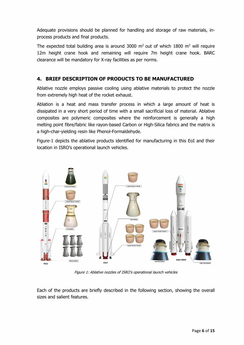
Figure-1 depicts the ablative products identified for manufacturing in this EoI and their
location in ISRO’s operational launch vehicles.
Figure 1: Ablative nozzles of ISRO's operational launch vehicles
Each of the products are briefly described in the following section, showing the overall
sizes and salient features.
Page 7 of 15
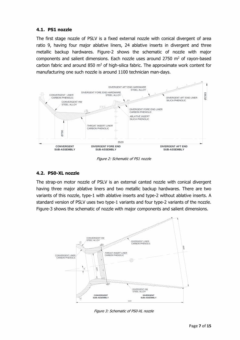
4.1. PS1 nozzle
The first stage nozzle of PSLV is a fixed external nozzle with conical divergent of area
ratio 9, having four major ablative liners, 24 ablative inserts in divergent and three
metallic backup hardwares. Figure-2 shows the schematic of nozzle with major
components and salient dimensions. Each nozzle uses around 2750 m2 of rayon-based
carbon fabric and around 850 m2 of high-silica fabric. The approximate work content for
manufacturing one such nozzle is around 1100 technician man-days.
3520
CONVERGENT
SUB-ASSEMBLY
DIVERGENT FORE END
SUB-ASSEMBLY
DIVERGENT AFT END
SUB-ASSEMBLY
DIVERGENT FORE END LINER
CARBON PHENOLIC
THROAT INSERT LINER
CARBON PHENOLIC
DIVERGENT AFT END LINER
SILICA PHENOLICCONVERGENT HW
STEEL ALLOY
DIVERGENT FORE END HARDWARE
STEEL ALLOY
DIVERGENT AFT END HARDWARE
STEEL ALLOY
Ø2383
Ø790
ABLATIVE INSERT
SILICA PHENOLIC
CONVERGENT LINER
CARBON PHENOLIC
Figure 2: Schematic of PS1 nozzle
4.2. PS0-XL nozzle
The strap-on motor nozzle of PSLV is an external canted nozzle with conical divergent
having three major ablative liners and two metallic backup hardwares. There are two
variants of this nozzle, type-1 with ablative inserts and type-2 without ablative inserts. A
standard version of PSLV uses two type-1 variants and four type-2 variants of the nozzle.
Figure-3 shows the schematic of nozzle with major components and salient dimensions.
THROAT INSERT LINER
CARBON PHENOLIC
DIVERGENT LINER
CARBON PHENOLIC
CONVERGENT HW
STEEL ALLOY
CONVERGENT LINER
CARBON PHENOLIC
9°
1519
Ø988
Ø357
DIVERGENT HW
STEEL ALLOY
CONVERGENT
SUB-ASSEMBLY
DIVERGENT
SUB-ASSEMBLY
PS0-XL NOZZLE ASSEMBLY
Figure 3: Schematic of PS0-XL nozzle

Page 8 of 15
Each nozzle uses around 1050 m2 of rayon-based carbon fabric. The approximate work
content for manufacturing one such nozzle is around 450 technician man-days.
4.3. HPS3 nozzle
The third stage nozzle of PSLV is a sub-merged flex nozzle with contoured divergent of
area ratio 70. The nozzle consists of flex-seal sub-assembly (which enables nozzle
actuation during operation), Graphite/Carbon-Carbon throat, five ablative liners, two
metallic backup hardwares and composite structural backup for the divergent region.
Figure-4 shows the schematic of nozzle with major components and salient dimensions.
Each nozzle uses around 725 m2 of rayon-based carbon fabric and around 15 m2 of high-
silica fabric. The approximate work content for manufacturing one such nozzle is around
530 technician man-days.
DIVERGENT AFT END LINER
CARBON PHENOLIC
COMLAINCE RING
ALUMINUM ALLOY
TBU CARBON PHENOLIC
TBU SILICA PHENOLIC
FSTP LINER
CARBON PHENOLIC
NOSE INSERT LINER
CARBON PHENOLIC
THROAT
GRAPHITE
FLEX SEAL
SUB ASSEMBLY
SUBMERGED
SUB ASSEMBLY
DIVERGENT HW
ALUMINUM ALLOYTHROAT HOUSING HW
ALUMINUM ALLOY
Ø166
1792
Ø1380.5
CONVERGENT
SUB-ASSEMBLY
DIVERGENT
SUB-ASSEMBLY
Figure 4: Schematic of HPS3 nozzle
4.4. GS1 nozzle
The first stage nozzle of GSLV is a fixed external nozzle with conical divergent of area
ratio 9 which is similar to PS1 nozzle, only difference being non-existence of ablative
inserts in divergent region. Figure-5 shows the schematic of this nozzle with major
Ø790
3520
Ø2383
CONVERGENT
SUB-ASSEMBLY
DIVERGENT FORE END
SUB-ASSEMBLY
DIVERGENT AFT END
SUB-ASSEMBLY
DIVERGENT FORE END LINER
CARBON PHENOLIC
THROAT INSERT LINER
CARBON PHENOLIC
DIVERGENT AFT END LINER
SILICA PHENOLIC
CONVERGENT LINER
CARBON PHENOLIC
CONVERGENT HW
STEEL ALLOY
DIVERGENT FORE END HARDWARE
STEEL ALLOY
DIVERGENT AFT END HARDWARE
STEEL ALLOY
Figure 5: Schematic of GS1 nozzle

Page 9 of 15
components and salient dimensions. Each nozzle uses around 2750 m2 of rayon-based
carbon fabric and around 800 m2 of high-silica fabric. The approximate work content for
manufacturing one such nozzle is around 900 technician man-days.
4.5. S200 nozzle
The strap-on nozzle of GSLV Mk3 is a submerged flex nozzle with contoured divergent
having area ratio of 12. Figure-6 shows the schematic of the nozzle having eight ablative
liners, four metallic hardwares and composite structural backup in addition to flex-seal.
Each nozzle uses around 7750 m2 of rayon-based carbon fabric and around 225 m2 of
high-silica fabric. The approximate work content for manufacturing one such nozzle is
around 1960 technician man-days.
DIVERGENT AFT END LINER
CARBON PHENOLIC
CONVERGENT
SUB-ASSEMBLY
Ø8
97
3474
HS200 FLEX NOZZLE ASSEMBLY
DIVERGENT FORE END LINER
CARBON PHENOLIC
DIVERGENT FORE END
SUB-ASSEMBLY
DIVERGENT AFT END
SUB-ASSEMBLY
THROAT ENTRY LINER
CARBON PHENOLIC
NOSE INSERT LINER
CARBON PHENOLIC
NOSE ENTRY LINER
CARBON PHENOLIC
FSTP HW
ALUMINUM ALLOY
FSTP BACKUPLINER
SILICA PHENOLIC SUBMERGED
SUB ASSEMBLY
FLEX SEAL
SUB ASSEMBLYFSTP LINER
CARBON PHENOLIC
COMPOSITE STRUCTURAL BACKUP
CARBON EPOXYDIVERGENT AFT END HARDWARE
STEEL ALLOYDIVERGENT FORE END HARDWARE
STEEL ALLOY
NOZZLE CLOSURE
NYLON
THROAT HOUSING
ALUMINUM ALLOY
Ø3
083
THROAT INSERT LINER
CARBON PHENOLIC
Figure 6: Schematic of S200 nozzle
4.6. Liquid engine throat
The liquid engine of all the three launch vehicles uses ablative throat made of silica-
phenolic. The throat has two variants, namely conical and contoured versions as shown
in figure-7. Each throat uses around 125 m2 of high-silica fabric. The approximate work
content in manufacturing one such throat is around 75 technician man-days.
Ø4
75 Ø3
06
405
Ø3
06
Ø4
75
330
Type-2 (for PSLV/GSLV/GSLV Mk3)Type-1 (GLSV)
Figure 7: Schematic of liquid engine throat

Page 10 of 15
5. BRIEF DESCRIPTION OF MANUFACTURING PROCESS
A nozzle assembly consists of two or more sub-assemblies, and each sub-assembly
consists of one or more ablative liners bonded to metallic backup structural hardware or
a composite backup is provided over the liner. A brief description of generic procedure
for the fabrication of liner. Sub-assembly and nozzle assembly is given in following
sections.
5.1. Liner processing
An ablative liner is processed by either winding prepreg tapes or layup of prepreg plies
over a mandrel, curing the wound mass along with mandrel under simultaneous
application of vacuum, temperature and pressure and machining the extracted cured
liner as per the fabrication drawing. Figure-8 shows the flowchart of a generic procedure
of liner fabrication.
Figure 8: Typical flowchart of ablative liner fabrication process
A brief description of each of these stages is given below.
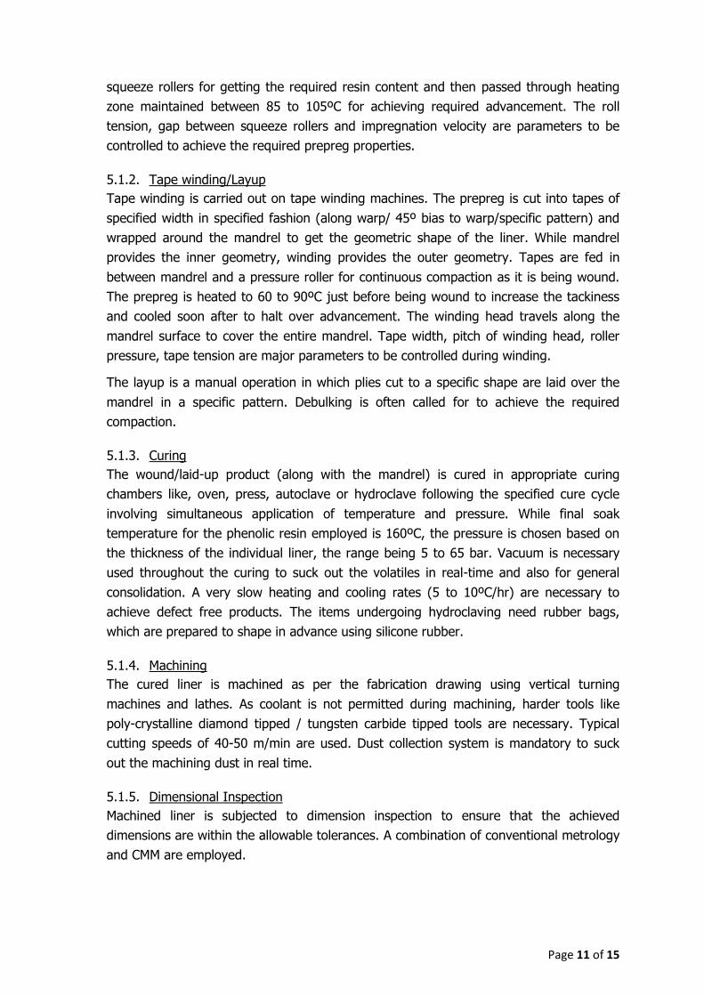
5.1.1. Impregnation
This process involves wetting of the reinforcement fabric (carbon or silica fabric rolls)
with the phenolic resin to obtain ‘prepreg’ having specified resin content and
advancement. The fabric after preheating passes under tension through a resin bath and
Tape Winding/Layup
Curing
NDT
Machining
Impregnation
Liner acceptance
End-ring Specimen testing
Dimensional inspection
Fabric Resin
Page 11 of 15
squeeze rollers for getting the required resin content and then passed through heating
zone maintained between 85 to 105ºC for achieving required advancement. The roll
tension, gap between squeeze rollers and impregnation velocity are parameters to be
controlled to achieve the required prepreg properties.
5.1.2. Tape winding/Layup
Tape winding is carried out on tape winding machines. The prepreg is cut into tapes of
specified width in specified fashion (along warp/ 45º bias to warp/specific pattern) and
wrapped around the mandrel to get the geometric shape of the liner. While mandrel
provides the inner geometry, winding provides the outer geometry. Tapes are fed in
between mandrel and a pressure roller for continuous compaction as it is being wound.
The prepreg is heated to 60 to 90ºC just before being wound to increase the tackiness
and cooled soon after to halt over advancement. The winding head travels along the
mandrel surface to cover the entire mandrel. Tape width, pitch of winding head, roller
pressure, tape tension are major parameters to be controlled during winding.
The layup is a manual operation in which plies cut to a specific shape are laid over the
mandrel in a specific pattern. Debulking is often called for to achieve the required
compaction.
5.1.3. Curing
The wound/laid-up product (along with the mandrel) is cured in appropriate curing
chambers like, oven, press, autoclave or hydroclave following the specified cure cycle
involving simultaneous application of temperature and pressure. While final soak
temperature for the phenolic resin employed is 160ºC, the pressure is chosen based on
the thickness of the individual liner, the range being 5 to 65 bar. Vacuum is necessary
used throughout the curing to suck out the volatiles in real-time and also for general
consolidation. A very slow heating and cooling rates (5 to 10ºC/hr) are necessary to
achieve defect free products. The items undergoing hydroclaving need rubber bags,
which are prepared to shape in advance using silicone rubber.
5.1.4. Machining
The cured liner is machined as per the fabrication drawing using vertical turning
machines and lathes. As coolant is not permitted during machining, harder tools like
poly-crystalline diamond tipped / tungsten carbide tipped tools are necessary. Typical
cutting speeds of 40-50 m/min are used. Dust collection system is mandatory to suck
out the machining dust in real time.
5.1.5. Dimensional Inspection
Machined liner is subjected to dimension inspection to ensure that the achieved
dimensions are within the allowable tolerances. A combination of conventional metrology
and CMM are employed.

Page 12 of 15
5.1.6. Non-Destructive Testing (NDT)
The liner is tested for possible defects like delamination, cracks, voids, resin rich
reasons, etc by ultrasonic testing and X-ray radiography in addition to visual testing.
5.1.7. End-ring specimen testing
Specimens are extracted from parted end-ring and tested for specified properties,
depending on the criticality of the liner.
5.1.8. Liner acceptance
The liner acceptance is based on adherence to the approved process as confirmed by
process log issued by online QC, acceptance of achieved dimensions, acceptance of NDT
observations and acceptance of tested properties from end-ring specimens.
The non-conformances if any should mandatorily be cleared by the appropriate forum in
VSSC before acceptance of the liner.
5.2. Sub-assembly operations
5.2.1. In cases of sub-assemblies having metallic backup hardware (issued as FIM), the
identified liners are adhesively bonded to the backup hardware using suitable
bonding fixtures. Two-part adhesive with limited pot life is used and hence
bonding needs proper planning. Parts to be bonded are dry suited before bonding
to ensure required interface conditions are met. Metallic bonding surfaces need
to be prepared by suitable methods like grit blasting. Bonded parts are then
machined as per sub-assembly fabrication drawing and subjected to dimensional
inspection and NDT for acceptance.
5.2.2. In case of sub-assemblies having composite structural backup, the composite
backup is provided directly on the liner. Glass-epoxy or Carbon-epoxy are the two
materials used either by wet process involving wetting the fabric with resin and
cutting and laying up of the resulting wet fabric over liner or dry process
involving laying up of prepreg. The backup is then cured at 100-125ºC following
specified cure cycle. The item is then machined as per sub-assembly fabrication
drawing and subjected to dimensional inspection and NDT as done for liner.
5.2.3. The sub-assembly is subjected to dimensional inspection and NDT to detect
possible defects like debonds, surface defects in liner, etc.
5.2.4. The sub-assembly acceptance is based on adherence to the approved process as
confirmed by process log issued by online QC, acceptance of achieved
dimensions and acceptance of NDT observations. The non-conformances if any
should mandatorily be cleared by appropriate forum in VSSC before acceptance
of the sub-assembly.

Page 13 of 15
5.3. Nozzle assembly operations
5.3.1. Two or more sub-assemblies of a nozzle are mechanically assembled using
fasteners torqued to specified limits. All the interface elements like fasteners,
washers, O-rings, sealant putty, etc will be FIMs from VSSC.
5.3.2. All the interfaces are verified for necessary design conditions in a trial-assembly
before the final assembly and matched with expected interface conditions from
achieved dimensions of sub-assemblies.
5.3.3. Assembled nozzle is then placed inside a specially designed transportation
container and despatched.
6. PROCESS TOOLING
6.1. Each liner requires a specific mandrel for fabrication, with provisions for vacuum
application, vacuum bagging, mounting on winding machine, handling, etc. The
vendor shall realize each of the mandrels in adequate numbers as per the mandrel
design provided by VSSC.
6.2. Fixtures are necessary for bonding of liners to backup hardwares and for
machining of liners and sub-assemblies. The vendor shall realize each of these
fixtures as per the fixture design provided by VSSC.
6.3. Assembly stands are necessary for nozzle assembly operations, which shall be
realized by the vendor as per the design provided by VSSC.
6.4. The vendor shall also realize transportation containers for safe handling of finished
products to the place specified by VSSC in adequate numbers.
7. QUALITY REQUIREMENT
7.1. Maintaining necessary quality control during manufacturing is the responsibility of
the vendor
7.2. The manufacturing shall be strictly as per the process document provided by VSSC
7.3. Considering process intensive nature of composites in general and the single use
nature of ablative products in particular, strict online quality monitoring is
mandatory. VSSC may depute resident engineers for online quality surveillance.
7.4. VSSC will conduct periodic quality audit for verifying adherence to the quality
protocols.

Page 14 of 15
8. DELIVERY SCHEDULES
The vendor should be able to meet the delivery schedule as follows:
8.1. The procurement and commissioning of the facilities should be completed within a
period of 18 months from the date of order placement
8.2. First-off products should be delivered within 24 months from the date of order
placement
8.3. Subsequent to clearance for regular production, products shall be delivered at
regular intervals as follows:
PS1 nozzle: 1 nozzle every 36 days
PS0-XL nozzle: 5 nozzles every month
HPS3 nozzle: 1 nozzle every 36 days
GS1 nozzle:1 nozzle every 6 months
S200 nozzle:1 nozzle every 45 days
Liquid engine throat: ~5 throats every 2 months
9. VENDOR EVALUATION CRITERIA
The following are the essential criteria to be fulfilled by the vendor:
9.1. Should be an aerospace manufacturing industry having at least three orders worth
`1 crore or more in the past three years
9.2. Should have experience and facilities for general composite manufacturing
9.3. Should have healthy financial conditions with minimum turnover of `50 crores
consistently for past 3 years
9.4. Should have the ability to invest large capital (more than `100 crores) over long
term (more than 3 yrs)
9.5. Should have end-to-end capability for
i. Planning/identifying and procurement of manufacturing equipment
ii. Design and realization of tooling
iii. production planning and process control
iv. independent quality control system
v. qualified and calibrated inspection/testing facilities
9.6. Should have adequate and competent manpower to take up aerospace
manufacturing of similar complexity
9.7. Should setup the essential manufacturing facilities in India under one-roof listed in
section 3 for
i. Impregnation
Page 15 of 15
ii. Tape winding
iii. Moulding and curing
iv. Machining
v. Bonding and assembly
Note: Sub-contracting of operations related to these facilities will not be permitted
and details of equipment proposed to be procured is to be shared with VSSC
9.8. It is preferred to have the NDT and other inspection facilities in the vicinity of
manufacturing facilities. In case the party plans to outsource these activities, it
should be with the concurrence of VSSC. However, the responsibility of meeting
the quality requirement and delivery schedule lies with the party.
Vendors who express interest will have to mandatorily visit VSSC on a mutually
convenient date and present their interest and capabilities to meet above requirements.
VSSC also reserves the right to visit the party and verify the proofs for the claims made
by the party for meeting the vendor evaluation criteria.
10. SUBMISSION OF EoI
Interested vendors who understand the technical requirements as mentioned in this
document and confirm their eligibility to the evaluation criteria given in section 9 are
requested to express their interest to take up this manufacturing activity.