Investigation Work Plan for Material Disposal Area B at ... · PDF fileInvestigation Work Plan...
55
LA-UR-04-3713 June 2004 ER2004-0243 Investigation Work Plan for Material Disposal Area B at Technical Area 21, Solid Waste Management Unit 21-015 CD included with this document
Transcript of Investigation Work Plan for Material Disposal Area B at ... · PDF fileInvestigation Work Plan...

LA-UR-04-3713 June 2004
ER2004-0243
Investigation Work Plan for Material Disposal Area B at Technical Area 21, Solid Waste Management Unit 21-015
CD included with this
document

Prepared by Risk Reduction and Environmental Stewardship–Remediation Services
Los Alamos National Laboratory, an affirmative action/equal opportunity employer, is operated by the University of California for the United States Department of Energy under contract W-7405-ENG-36.
This report was prepared as an account of work sponsored by an agency of the United States Government. Neither the Regents of the University of California, the United States Government nor any agency thereof, nor any of their employees make any warranty, express or implied, or assume any legal liability or responsibility for the accuracy, completeness, or usefulness of any information, apparatus, product, or process disclosed, or represent that its use would not infringe privately owned rights. Reference herein to any specific commercial product, process, or service by trade name, trademark, manufacturer, or otherwise does not necessarily constitute or imply its endorsement, recommendation, or favoring by the Regents of the University of California, the United States Government, or any agency thereof.
Los Alamos National Laboratory strongly supports academic freedom and a researcher's right to publish; as an institution, however, the Laboratory does not endorse the viewpoint of a publication or guarantee its technical correctness. By acceptance of this article, the publisher recognizes that the U.S. Government retains a nonexclusive, royalty-free license to publish or reproduce the published form of this contribution, or to allow others to do so, for U.S. Government purposes. Los Alamos National Laboratory requests that the publisher identify this article as work performed under the auspices of the U.S. Department of Energy.
Disclaimer This document contains data on radioactive materials, including source, special nuclear, and by-product material. The management of these materials is regulated under the Atomic Energy Act and is specifically excluded from regulation under the Resource Conservation and Recovery Act and the New Mexico Hazardous Waste Act. These data are provided to the New Mexico Environment Department for informational purposes only.
LA-UR-04-3713
ER2004-0243
Investigation Work Plan for Material Disposal Area B at Technical Area 21,
Solid Waste Management Unit 21-015
June 2004
Responsible project leader:
Ron E. Rager Team Leader RRES-RS
Printed Name Signature Title Organization Date
Responsible UC representative:
David McInroy Deputy
Project Director RRES-RS Printed Name Signature Title Organization Date
Responsible DOE representative:
David Gregory Federal Project
Director DOE-LASO Printed Name Signature Title Organization Date

ER2004-0243 v June 2004
EXECUTIVE SUMMARY
This investigation work plan describes the sampling and analysis requirements and investigatory methodology for characterizing the contents of Material Disposal Area (MDA) B, Solid Waste Management Unit (SWMU) 21-015, at Technical Area 21 within Los Alamos National Laboratory (LANL or the Laboratory). Based on a conservative estimate of potential radiological waste inventory, MDA B has been categorized as a Hazard Category 3 nuclear facility, requiring special consideration of radiological and hazardous materials work-related safety issues.
From 1944 until 1948, MDA B received waste related to LANL processes. There are no official waste inventory records for MDA B. According to historical data, anecdotal information, and process knowledge, the types of waste disposed at the landfill were highly variable. Disposal trenches may contain radioactive and chemically contaminated laboratory wastes, debris, and waste products from a water boiler as well as containers of solvents, chemical mixtures, and corrosive liquids and gasses. At least one truck contaminated with fission products from the Trinity test is buried in MDA B. Some degree of waste segregation practices is suggested by the presence of shallow chemical-disposal trenches as well as other larger trenches that were presumably for debris and other solid waste. Other documents state that there was no attempt to separate materials.
The principal objectives of the investigation prescribed by this work plan are (1) to characterize the types and estimate the quantities of waste in MDA B; (2) to characterize the radiological, organic chemical, and inorganic chemical concentrations in the soil and rock adjacent to the disposal trench sides and bottom; and (3) to generate operational performance data for potential future corrective actions at the MDA B disposal trenches. Achieving these objectives requires direct excavation into the MDA B disposal trenches.
This work plan is part of a phased approach outlining the methodology directing and documenting the decisions made prior to, and during, field operations. During field operations, brief milestone reports will be prepared to keep the New Mexico Environment Department (NMED) apprised of field conditions and the progress of activities. Any deviations from the work plan will be documented. Because of the proximity of MDA B to the city of Los Alamos and businesses immediately across the street, public meetings will be held during the planning and execution of field activities. In addition, appropriate training, including emergency warning and response, will be conducted for those businesses that will be affected. Designed safety features such as temporary enclosures will help isolate the planned field activities from the adjacent businesses and surrounding environment. Work activities will be planned to minimize the impact on adjacent businesses. To assess possible issues, plan and control the work environment, and prevent damage to the surrounding environment, an implementation plan will be developed.
To characterize buried waste, eight or more exploratory trenches will be advanced laterally across the disposal trenches and will penetrate the entire local thickness and depth of the landfill. The locations of the exploratory trenches will be based on historical, anecdotal, and geophysical information and will be chosen to intercept the disposal trenches and to capture—to the extent practical—a representation of the disposal trench contents. Test pits will be excavated to augment exploratory trench observations and data. Excavation activities will be performed inside a temporary mobile structure to provide access control, protect the operations from environmental factors, and impede off-site exposure to excavated material.
Because of the lack of knowledge about the disposal trench contents and the possible hazards associated with excavating into radiologically and chemically contaminated materials, a flexible plan, with appropriate regulator interaction, allows for an increase in the number of exploratory trenches, changes to the configuration of the exploratory trenches, the ability to isolate and bypass high-risk areas when
Investigation Work Plan for MDA B
June 2004 vi ER2004-0243
encountered, and control over the quantity of material excavated. Samples for waste and in-situ material characterization will be collected based on field data and physical observations. Samples will be analyzed at quality-controlled laboratories for a comprehensive suite of analytes. Analytical and observational data will be used to establish the waste types and volumes within the disposal trenches.
Materials removed from the exploratory trenches will be evaluated to ensure proper handling in accordance with health and safety requirements. To address anticipated disposal trench material-handling scenarios that could be encountered during the field investigation, a decision tree and analysis table is presented in this plan. After additional specific planning, any bypassed materials will be removed from the excavation for proper containment and storage, characterization, packaging, and transportation to an approved disposal facility, on a case-by-case basis. Industrial and low-level radioactive waste, as well as uncontaminated material, may be returned to the excavation in a segregated fashion. Records will be kept of the types and locations of any material returned to the excavation in order to facilitate future potential actions.
Analysis of samples taken at locations immediately below and adjacent to the disposal trenches during exploratory trench and test pit installation will supplement the existing data in order to better define the nature and extent of contamination in the underlying soil and rock. These data will be reported as they become available as part of the milestone reports to the NMED to monitor progress and results.
Appendix B, the historical investigation report, describes the results of investigations of contaminants that may have been discharged or released at MDA B during historical operations at the facility. The investigation includes known and suspected sources for potential groundwater contaminants, and a review of existing data and other information acquired during previous investigations. Included are results of the previously undocumented 1998 Resource Conservation and Recovery Act (RCRA) facility investigation.

ER2004-0243 vii June 2004
CONTENTS
1.0 INTRODUCTION............................................................................................................................... 1 1.1 General Site Information........................................................................................................ 1 1.2 Investigation Objectives......................................................................................................... 1
2.0 BACKGROUND ................................................................................................................................ 2 2.1 Operational History ................................................................................................................ 2 2.2 Summary of Historical Investigations .................................................................................... 3
2.2.1 Surface Soils ........................................................................................................... 3 2.2.2 Subsurface Tuff ....................................................................................................... 4 2.2.3 Summary of MDA B Contaminants ......................................................................... 4
3.0 SITE CONDITIONS........................................................................................................................... 5 3.1 Surface Conditions ................................................................................................................ 5
3.1.1 Surface Water ......................................................................................................... 6 3.1.2 Surface Soils ........................................................................................................... 6
3.2 Subsurface Conditions .......................................................................................................... 6 3.2.1 Stratigraphy ............................................................................................................. 6 3.2.2 Cliff Retreat and Fractures ...................................................................................... 7 3.2.3 Hydrogeology .......................................................................................................... 7
4.0 SCOPE OF ACTIVITIES ................................................................................................................... 8 4.1 Justification for Alternative Scope of Work.......................................................................... 10 4.2 Regulatory Basis for Technical Approach ........................................................................... 11 4.3 Health & Safety and Environmental Protection ................................................................... 12
4.3.1 DSA ....................................................................................................................... 12 4.3.2 Pre-fieldwork Activities .......................................................................................... 13 4.3.3 Environmental Protection Monitoring .................................................................... 13 4.3.4 Emergency Response........................................................................................... 13
4.4 Excavation of Disposal Trench Contents ............................................................................ 14 4.4.1 Evaluation of Excavation Methods ........................................................................ 15 4.4.2 Guidelines for Excavated Materials....................................................................... 15 4.4.3 Test Pit Excavation................................................................................................ 15
4.5 Screening for IDLH Conditions ............................................................................................ 16 4.6 Initial Segregation by Material Type .................................................................................... 16 4.7 Removal of Chemical Containers ........................................................................................ 16 4.8 Exploratory Trench Logging and Identification of Excavated Materials .............................. 17 4.9 Hazard Characterization (HazCat) Screening ..................................................................... 17 4.10 Waste Management............................................................................................................. 17
4.10.1 Waste Compositing ............................................................................................... 17 4.10.2 Waste Packaging .................................................................................................. 18
4.11 Definitive Identification Screening ....................................................................................... 18 4.12 Inventory Management and Tracking.................................................................................. 18 4.13 Sampling of Exploratory Trench Bottoms and Sidewalls..................................................... 19 4.14 Surveying Locations and Features of Excavations ............................................................. 19 4.15 Exploratory Trench Backfilling, Compaction, and Clean Cover Replacement .................... 19
5.0 INVESTIGATION METHODS ......................................................................................................... 19 5.1 Excavation Methods ............................................................................................................ 20 5.2 Test Pit Methods.................................................................................................................. 21
Investigation Work Plan for MDA B
June 2004 viii ER2004-0243
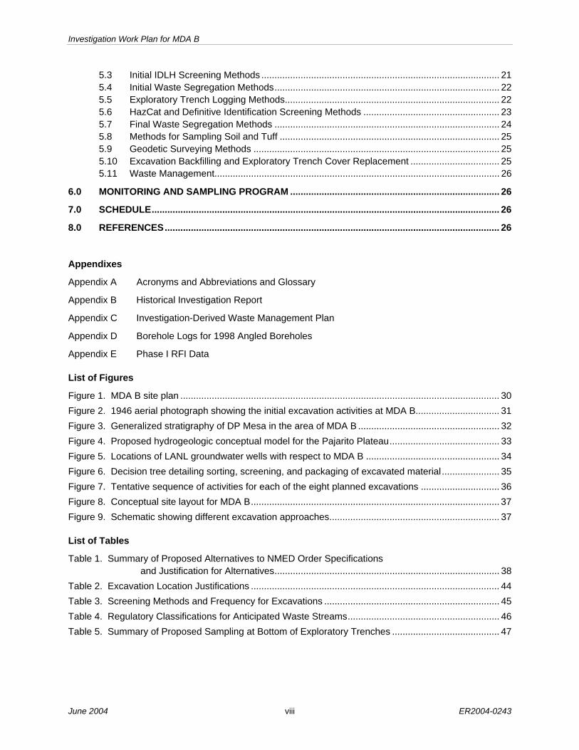
5.3 Initial IDLH Screening Methods ........................................................................................... 21 5.4 Initial Waste Segregation Methods...................................................................................... 22 5.5 Exploratory Trench Logging Methods.................................................................................. 22 5.6 HazCat and Definitive Identification Screening Methods .................................................... 23 5.7 Final Waste Segregation Methods ...................................................................................... 24 5.8 Methods for Sampling Soil and Tuff .................................................................................... 25 5.9 Geodetic Surveying Methods .............................................................................................. 25 5.10 Excavation Backfilling and Exploratory Trench Cover Replacement .................................. 25 5.11 Waste Management............................................................................................................. 26
6.0 MONITORING AND SAMPLING PROGRAM ................................................................................ 26 7.0 SCHEDULE..................................................................................................................................... 26 8.0 REFERENCES................................................................................................................................ 26
Appendixes
Appendix A Acronyms and Abbreviations and Glossary
Appendix B Historical Investigation Report
Appendix C Investigation-Derived Waste Management Plan
Appendix D Borehole Logs for 1998 Angled Boreholes
Appendix E Phase I RFI Data
List of Figures
Figure 1. MDA B site plan .......................................................................................................................... 30 Figure 2. 1946 aerial photograph showing the initial excavation activities at MDA B................................ 31 Figure 3. Generalized stratigraphy of DP Mesa in the area of MDA B ...................................................... 32 Figure 4. Proposed hydrogeologic conceptual model for the Pajarito Plateau.......................................... 33 Figure 5. Locations of LANL groundwater wells with respect to MDA B ................................................... 34 Figure 6. Decision tree detailing sorting, screening, and packaging of excavated material...................... 35 Figure 7. Tentative sequence of activities for each of the eight planned excavations .............................. 36 Figure 8. Conceptual site layout for MDA B............................................................................................... 37 Figure 9. Schematic showing different excavation approaches................................................................. 37
List of Tables
Table 1. Summary of Proposed Alternatives to NMED Order Specifications and Justification for Alternatives...................................................................................... 38
Table 2. Excavation Location Justifications ............................................................................................... 44 Table 3. Screening Methods and Frequency for Excavations ................................................................... 45 Table 4. Regulatory Classifications for Anticipated Waste Streams.......................................................... 46 Table 5. Summary of Proposed Sampling at Bottom of Exploratory Trenches ......................................... 47

ER2004-0243 1 June 2004
1.0 INTRODUCTION
1.1 General Site Information
Los Alamos National Laboratory (LANL or the Laboratory) is a multidisciplinary research facility owned by the US Department of Energy (DOE) and managed by the University of California. The Laboratory is located in north-central New Mexico, approximately 60 mi northeast of Albuquerque and 20 mi northwest of Santa Fe. The Laboratory site covers 40 mi2 of the Pajarito Plateau, which consists of a series of finger-like mesas separated by deep canyons containing perennial and intermittent streams running from west to east. Mesa tops range in elevation from approximately 6200 to 7800 ft above sea level (asl).
The Laboratory’s Risk Reduction and Environmental Stewardship Division–Remediation Services (RRES-RS) project, formerly the Environmental Restoration (ER) Project, is participating in a national effort by the DOE to clean up sites and facilities formerly involved in weapons research and production. The goal of the RRES-RS is to ensure that DOE’s past operations do not threaten human or environmental health and safety in and around Los Alamos County, New Mexico. To achieve this goal, the project investigates sites potentially contaminated by past Laboratory operations. The site discussed in this plan is a site where solid wastes had been placed at one time (i.e., it is a solid waste management unit [SWMU]).
This investigation, including sampling and analysis, is being conducted under the requirements of the Resource Conservation and Recovery Act (RCRA) and in accordance with the Hazardous and Solid Waste Amendments of 1984 (HSWA) and follows the requirements in Module VIII of the Laboratory’s Hazardous Waste Facility Permit (EPA 1990, 01585.2). Module VIII was issued to the Laboratory by the US Environmental Protection Agency (EPA) on May 23, 1990, and modified on May 19, 1994 (EPA 1994, 44146.2). Radionuclides are regulated under DOE Order 5400.5, “Radiation Protection of the Public and the Environment” (proposed rule 10 CFR 834.5). As agreed to with the New Mexico Environment Department (NMED), the purposes of the work described in this plan are to characterize the disposal trench contents and further define nature and extent.
In accordance with Module VIII, the nature and extent of releases of hazardous waste or hazardous constituents are determined through the RCRA facility investigation (RFI) process. Under the RRES-RS project, the Laboratory implements the RFI process for those sites under the administrative authority of DOE.
Material Disposal Area (MDA) B is an inactive subsurface disposal site, designated as SWMU 21-015, that might contain both hazardous and radiological chemicals. The site is located in Technical Area 21 (TA-21), on Delta Prime (DP) Mesa (a mesa separating Los Alamos Canyon and DP Canyon) (Appendix B, Figures B-1, B-2). MDA B occupies approximately 6 acres and consists of multiple disposal trenches (Figure 1). From 1944 until it closed in 1948, MDA B received process wastes from operations within TA-21 at DP East and DP West. The wastes disposed of at MDA B were highly heterogeneous, primarily radioactively contaminated laboratory wastes and debris, and limited liquid chemical waste; however, a formal waste inventory was not maintained (LANL 1991, 07529.1).
1.2 Investigation Objectives
MDA B has been investigated numerous times since disposal operations were discontinued. These investigations focused on surface characterization and subsurface releases outside the actual disposal trenches. The nature and extent of contamination released from MDA B is generally known; however, none of the investigations have specifically targeted the characterization of the contents of the MDA B disposal trenches and the soil or tuff near the interface with the waste-disposal trenches. As discussed in the historical investigation report (HIR) (Appendix B) and in section 2, waste-disposal practices during

Investigation Work Plan for MDA B
June 2004 2 ER2004-0243
MDA B’s operational lifetime are not well documented. The contents of the MDA B disposal trenches are largely uncharacterized.
The objectives of the investigation described in this work plan are to
• characterize the types of waste and estimate the quantities of waste in MDA B;
• characterize (using quantitative screening methods and off-site anaytical laboratory data) the radiological, organic chemical, and inorganic chemical concentrations in fill material, soil, and rock near the interface with the waste-disposal trenches; and
• generate operational performance data for potential future corrective actions within the MDA B disposal trenches.
Meeting these objectives requires direct excavation into the MDA B disposal trenches.
Analytical and observational data will be used to identify contaminants, estimate volumes, and map the types and physical forms of the various wastes contained in the disposal trenches. These data will also be used to refine the health and safety protocols required for future activities associated with the disposal trenches. The operational performance data will be used to determine the safest and most efficient methods for excavating within the disposal trenches and for handling, characterizing, segregating, and disposing of excavated materials.
Data about the residual radiological and hazardous chemical concentrations will be collected from fill, soil, or rock in the side walls of the excavations and from native tuff in the bottom of the exploratory trenches. These data will be used to assess the nature and extent of contamination directly beneath the landfill.
Defining the contents of the disposal trenches will help expedite progress to the final remedy. Instead of waiting for the corrective measures study phase, source characterization activities are proposed in this work plan. This will provide flexibility for further expediting corrective action based on the results of the source term investigation. This approach makes it possible to meet the deadlines for completing the investigation report and the final remedy as specified in the Order issued by the NMED. This work plan describes the rationale for the data collection activities, and it specifies the sampling and excavation methodologies and protocols that will be employed for collecting, analyzing, and evaluating the data required to meet the objectives of this investigation.
2.0 BACKGROUND
Appendix B of this document is the HIR. The HIR provides the most complete information regarding MDA B’s background. A summary of the relevant background information is provided in this section. Complete details are in the HIR, including specific analytical results, the approach to selecting exploratory trench locations, and the planning for waste characterization and sampling.
2.1 Operational History
Historical records state that MDA B consisted of several disposal trenches approximately 300 ft long, 15 ft wide, and 12 ft deep, and that MDA B included at least one smaller, shallower trench on the eastern end of the site (LANL 1991, 07529.1). Waste disposal at MDA B ceased in 1948. A circa 1946 aerial photograph shows the initial excavation activities at MDA B (Figure 2). Geophysical surveys were conducted in 1996, 1997, and 1998 to delineate the location and number of disposal trenches at MDA B (Ferguson et al. 1998, 58212.1; Bay Geophysical 1998, 64146; Bay Geophysical 1998, 64147; Thavoris 2001, 83862.1). The results of the surveys were interpreted as several large trenches. One to three of

Investigation Work Plan for MDA B
ER2004-0243 3 June 2004
these comprise the western portion of the MDA and one large trench comprises the eastern portion (Appendix B, Figure B-26).
From 1944 until 1948, the Laboratory’s primary waste-producing operations at TA-21 were located at DP East and DP West. By the fall of 1944, the LANL Chemistry Division had developed several separation techniques to recover plutonium from residues. Solids from incinerator reduction operations were dissolved in nitric and hydrofluorous acids to recover trace amounts of plutonium (Merrill 1990, 11721.1). During the early 1940s, plutonium recovery was conducted until the maximum concentration for plutonium in solution was 10-4 g/L. Once this concentration was reached, the solution was discarded. These processes are described to provide an overview of the materials that were potentially disposed of at MDA B.
There are several indications that hazardous chemicals may be present at MDA B. In 1948, a portion of the disposal area caught fire. During the fire, several cartons of waste caused minor explosions and, on one occasion, a cloud of pink gas arose from the debris in the dump. The chemicals disposed of included old bottles of organic compounds such as perchlorates, ethers, and solvents. A 1987 DOE document also stated that lecture bottles, mixtures of spent chemicals, old chemicals, and corrosive gases may be in the trench(es) at the east end of MDA B (DOE 1986, 08657.1).
The principal radioactive contaminants consist of the types of radioactive materials used at the time: plutonium, polonium, uranium, americium, curium, radioactive lanthanum (RaLa), and actinium. Additionally, there could be waste products possibly contaminated with either uranium-235 or cesium-137 from the water boiler reactor (Meyer 1952, 28154.2). Short-lived radionuclides, such as RaLa, are no longer present due to radioactive decay. The majority of the radioactively contaminated waste probably consisted of paper, rags, rubber gloves, glassware, and small metal apparatus placed in cardboard boxes by the waste originator and sealed with masking tape. The remainder of the material consisted of metal, including air ducts and large metal apparatus. The latter type of material was placed in wooden boxes or wrapped with paper (Meyer 1952, 28154.2). At least one truck contaminated with fission products from the Trinity test is believed to be buried in MDA B (DOE 1986, 08657.1).
2.2 Summary of Historical Investigations
Detailed discussions of data from surface and subsurface investigations are presented in sections B-3 and B-4 of the HIR (Appendix B). The following subsections summarize the relevant results.
2.2.1 Surface Soils
Surface investigations at MDA B have included surface soil sampling and surface flux measurements of volatile organic compounds (VOCs). Sampling events occurred from 1966 to 2001.
It is difficult to directly relate MDA B surface concentrations to specific releases from MDA B. There have been various site-wide releases of chemicals to the surface at TA-21 from facility operations and stack emissions (LANL 1994, 26073.1; LANL 1995, 52350.1). Additionally, the surface at MDA B has been paved, reworked, and used as a pilot for a barrier project. The locations and concentrations of organic chemicals, inorganic chemicals, and radionuclides in surface soils are reported in Appendix B, sections B-3 and B-4.
Americium-241, cesium-137, plutonium-238, plutonium-239, and tritium were detected consistently across the surface of MDA B (Appendix B, Figure B-45). Plutonium-239 is the most consistently detected radionuclide and, along with tritium, is a site-wide contaminant based on 1992 mesa-wide survey data (LANL 1994, 26073.1; LANL 1995, 52350.1).

Investigation Work Plan for MDA B
June 2004 4 ER2004-0243
Organic chemicals were detected very infrequently at the surface of MDA B (Appendix B, Figure B-47). Lead and zinc were detected above background values consistently across MDA B. Other inorganic chemicals, including cadmium, copper, and mercury, were detected above background values across the site. The spatial distribution of inorganic chemicals in surface soils is shown in Appendix B, Figure B-46.
2.2.2 Subsurface Tuff
Three subsurface investigation campaigns were conducted at MDA B. These occurred in 1966 (Kennedy 1966, 00540.1), 1983 (LANL 1991, 07529.1), and in 1998 (unpublished data, presented in Appendix B of this report, section B-4.3.1). In 1966 and 1983, vertical boreholes were drilled alongside the disposal area boundary. The 1983 results indicated potential tritium contamination at depth. In 1998, seven angled boreholes were drilled beneath the disposal trenches in order to assess potential releases from the disposal trenches. Borehole logs from the 1998 drilling activities are included as Appendix D to this report. Lead was detected slightly above background at several depths in one angled borehole at the west end of the disposal site (Location ID 21-10557) and in one sample in another angled borehole in the central part of the site (Location ID 21-10551). Aluminum, arsenic, cadmium, mercury, and zinc were also detected at concentrations above background (LANL 1998, 59730) in the 1998 boreholes (Appendix B, Figure B-29).
Tritium was detected above background (LANL 1998, 59730) in six of seven boreholes (Appendix B, Figure B-29 and Table B-27). Borehole 21-10556 was the only borehole with no detections of tritium above background. The tritium concentration in borehole 21-10554 increased slightly over the length of the boring, but it showed a decrease in concentration in the deepest sample (Appendix B, Figures B-29 and B-36). Borehole 21-10554 is located beneath what is believed to be the chemical disposal trench. It appears that tritium has been released from the disposal trenches to the subsurface tuff. Americium-241 and strontium-90 were also detected in borehole 21-10554 and showed decreasing concentrations with depth (Appendix B, Figures B-28 and B-36). Uranium-234, -235, and -238 were detected above background in one sample in one borehole, 21-10557 (Appendix B, Figure B-40).
The pore-gas sampling results from the angled boreholes identified trace levels of several VOCs, primarily trichloroethene (TCE) and 1,1,1-trichloroethane (TCA), in the subsurface, in the parts per billion by volume (ppbv) range (Appendix B, Figure B-30). Pore-gas samples were collected using a borehole packer system and SUMMA canister collection method. The VOCs detected are generally consistent across the site (Appendix B, Table B-30).
2.2.3 Summary of MDA B Contaminants
Data from the site investigations conducted to date indicate that low concentrations of radionuclides, inorganic chemicals, and organic chemicals have been detected in surface soils and subsurface tuff. Appendix B’s Figures B-28, B-29, B-30, B-45, B-46, and B-47 are plan view maps showing the locations and concentrations of inorganic chemicals and radionuclides detected above background (LANL 1998, 59730) and detected organic chemicals in the surface and subsurface of MDA B. Based on the review of the available data, the sources of surface and subsurface contamination are limited in nature and extent and are mainly related to past disposal practices at the MDA B disposal trenches.

Investigation Work Plan for MDA B
ER2004-0243 5 June 2004
3.0 SITE CONDITIONS
The following sections present the current surface features and the existing subsurface geologic characteristics beneath TA-21, in general, and MDA B, in particular. Known surface and subsurface traits and their potential effects on the occurrence and concentration of contaminants include
• a canyon-mesa terrain, which affects meteorological conditions and ecological habitats at the surface;
• a semi-arid climate with low precipitation and a high evapotranspiration rate, which limits the extent of subsurface moisture percolation, limiting the amount of moisture available for leaching radionuclides or other hazardous waste constituents; and
• a thick, relatively dry, unsaturated (vadose) zone, which greatly restricts or prevents downward migration of contaminants in the liquid phase through the vadose zone to the regional aquifer.
These and other elements of the environmental setting at MDA B are useful when evaluating site investigation data with respect to the potential impacts of contamination from historical site activities.
3.1 Surface Conditions
Elevation at the top of DP Mesa in the vicinity of MDA B ranges from 7160 ft to 7220 ft asl, with a gentle slope to the south. The canyon slope ranges from 7060 ft asl in the bottom of BV Canyon to 7180 ft asl on the south edge of DP Mesa, immediately south of MDA B. Surface drainage from MDA B (e.g., rainwater, snow melt) flows south into BV Canyon (so named because it is adjacent to MDAs B and V), a shallow tributary of Los Alamos Canyon (LA Canyon). Topography prevents MDA B surface runoff from flowing north into DP Canyon (Appendix B, Figure B-6).
Occupying approximately 6 acres (2.4 hectares), MDA B consists of three areas:
1. a small, soil-covered, vegetated area at the extreme western end of MDA B (approximately 105 ft by 150 ft);
2. a large asphalt-paved area occupying the long western leg and the central portion of the site (approximately 1500 ft long by 120 ft wide); and
3. a soil-covered, vegetated area occupying the eastern leg of MDA B (approximately 600 ft long by 150 ft wide).
None of the three areas has any surface structures or utilities, and all are enclosed by a galvanized steel chainlink fence. Vegetation has penetrated portions of the asphalt pavement through cracks, and trees line a portion of the northern boundary of the site. An air monitoring station is located on the outside of the east fence.
The area to the west of MDA B is vacant but was the former location of a residential trailer park. To the east of MDA B are SWMUs 21-027(d)-99, 21-018(a)-99 (MDA V), and 21-024(e)-99. To the north are SWMUs 21-024(f) and 21-013 (d,e); to the northwest is SWMU 21-029 (DP Tank Farm). To the southwest are SWMUs 00-030(b)-00 and 00-010(a) (Appendix B, Figure B-3). The area immediately to the north of MDA B and south of DP Road is an unpaved area heavily used by commercial businesses along DP Road for parking and staging materials and deliveries. The area to the north of, and along, DP Road is paved and occupied by commercial buildings. The businesses include a building supply store, a newspaper office, a caterer, and other office space. Further to the east on DP Road, LANL has active

Investigation Work Plan for MDA B
June 2004 6 ER2004-0243
research facilities and office space at TA-21. DP Road is the only access for commercial businesses and LANL facilities.
3.1.1 Surface Water
Mesas of the Pajarito Plateau are generally dry, both on the surface and within the bedrock forming the mesa. Canyons range from wet to relatively dry; the wettest canyons contain continuous streams and perennial groundwater in the canyon-bottom alluvium. DP Mesa is bounded on the north by DP Canyon and on the south by Los Alamos Canyon and BV Canyon, which in turn flows into Los Alamos Canyon. DP and Los Alamos Canyons have intermittent flow sufficient to support alluvial groundwater systems whereas BV Canyon has only occasional stream flow which is insufficient to support alluvial groundwater.
There are no streams on DP Mesa; stormwater and snowmelt generally run off the mesa as sheet flow and in small drainages off the mesa sides. Runoff from MDA B consists of sheet flow into BV Canyon, which in turn flows into Los Alamos Canyon.
RRES-RS has developed a standard operating procedure (SOP) for assessing the potential for erosion and sediment transport at individual SWMUs (LANL-ER-SOP-2.01). Erosion potential is numerically rated from 1 to 100 using a matrix system. SWMUs that score greater than 60 have a high erosion potential. The erosion potential score for SWMU 21-015 (MDA B) is 17.9, indicating a low erosion potential.
3.1.2 Surface Soils
At TA-21, natural or undisturbed surface soil cover is limited, due to Laboratory operations such as waste disposal and building construction and demolition. The present-day mesa surface in the area of MDA B is predominantly asphalt and landfill cover material. Where undisturbed, soils on the mesa surface are thin and poorly developed. They tend to be sandy in texture near the surface and more clay-like beneath the surface. Soil profiles tend to be more poorly developed on the cliff-forming south-facing slopes than on the north-facing slopes, which tend to have higher organic content. A discussion of the soils in the Los Alamos area can be found in section 2.2.1.3 of the ER Project’s installation work plan (LANL 1998, 62060, pp. 2–21) and in Nyhan et al. (1978, 05702, pp 24–25).
3.2 Subsurface Conditions
None of the three MDA B areas has any underground utilities, underground storage tanks, or septic tanks associated with MDA B operations. There is an abandoned radioactive liquid waste line running along the southern boundary of the site, outside the fence, that served other LANL facilities. This waste line is not part of SWMU 21-015. Outside the fence near the southeast corner of the site is a Los Alamos County sanitary sewer lift station. Buried water and communications lines are located under the area between the north fence and DP Road. A water hydrant is located inside the northwest corner of the fence.
3.2.1 Stratigraphy
The generalized stratigraphy of DP Mesa in the area of MDA B is shown in Figure 3. DP Mesa consists of Bandelier Tuff (Qbt) overlain by a thin layer of alluvium and soil. The Bandelier Tuff unit is subdivided into two members, in ascending order: the Otowi, and the Tshirege. MDA B is situated within the Tshirege Member, which is a compound cooling unit divided into four distinct cooling units (units 4, 3, 2, 1v/1g) (Broxton et al. 1995, 50121, pp. 45–51). Bedrock directly underlying TA-21 is cooling unit 3 (Qbt 3) of the Upper Tshirege, a cliff-forming tuff that is nonwelded to partially welded. Below MDA B, the Otowi and Tshirege Members are separated at about 300 ft bgs by the Cerro Toledo (Qct) interval, a 10- to 40-ft-thick sequence of volcaniclastic sediments deposited in braided stream systems. The Bandelier Tuff and deposits of the Cerro Toledo interval are derived primarily from explosive volcanic eruptions in the Valles

Investigation Work Plan for MDA B
ER2004-0243 7 June 2004
Caldera approximately 1.2 million years ago (Goff 1995, 49682, p. 7). The basal Guaje Pumice Bed of the Otowi Member separates the Bandelier Tuff from the underlying clastic fanglomerate sediments of the Puye Formation (Tp). This feature may be locally absent in portions of TA-21.
3.2.2 Cliff Retreat and Fractures
According to a report on geomorphic studies at DP Mesa and vicinity (Reneau 1995, 50143.1, pp. 66–69), tributary stream systems and their canyons (possibly including BV Canyon and the upper reaches of DP Canyon) developed prior to incision of LA Canyon, and minimal cliff retreat has occurred in these canyons since then. A paleochannnel identified to extend over portions of the DP Mesa may also be related to the tributary stream system. The report goes on to say that exposure of most of the MDAs at TA-21 on DP Mesa through cliff retreat is improbable over periods exceeding 10,000 years. The exception, MDA V, is more difficult to evaluate. According to a fracture study conducted at TA-21, a relatively high-density fracture zone runs with a northerly strike through MDA V (Wohletz 1995, 54404.1). This zone may possibly be related to the Pajarito Fault system. Fracture characteristics of unit 2 of the Tshirege Member, which was the focus of this study, are very similar to previous fracture studies of unit 3, allowing for extrapolation of results to the rocks directly below TA-21. The study indicates that slant (angled) boreholes drilled in the direction S48E and N-S would optimize fracture intersections in the upper vadose zone under the MDAs at TA-21.
3.2.3 Hydrogeology
3.2.3.1 Infiltration
The proposed hydrogeologic conceptual model for the Pajarito Plateau (Figure 4) (LANL 1998, 59599, p. 5) predicts infiltration of water into the subsurface and the subsequent transport of water, vapor, and solutes through the upper regions of the vadose zone. This process is heavily influenced by surface conditions such as topography, surface water flow, and precipitation. The natural source of moisture in the vadose zone is precipitation, most of which is removed as runoff and evaporation and transpiration (or “evapotranspiration”) (LANL 1997, 63131). The subsurface movement of the remaining moisture (often referred to as recharge) is predominantly vertical in direction and is influenced by properties and conditions of the vadose zone.
Differences in degree of surface disturbance and the geologic properties of the tuff lead to differences in recharge rates. Mesa-top recharge can be locally significant when vegetation is removed, when soil and near-surface bedrock are disturbed, or when water is artificially added to the local hydrologic system by activities such as effluent disposal.
Two geologic properties of the Bandelier Tuff that significantly influence recharge rates are the degree of welding and devitrification. Both are effects from the prolonged presence of residual gases and high temperatures following deposition. Because different tuff units were deposited at different temperatures, and because individual units were laid out in variable thicknesses over different landscapes, cooling was not uniform. Consequently, welding varies spatially, both between and within separate depositional layers. Welded tuffs tend to be more fractured than nonwelded tuffs. Fractures within the tuff do not enhance the movement of dissolved contaminants unless saturated conditions exist.
Under unsaturated conditions, most of the open fractures beneath the site are expected to be completely dry, and the water will exist in the tuff matrix only. Only in situations when substantial infiltration occurs from the ground surface, as was potentially the case under the active absorption beds, will the fractures become wet and conduct water. However, modeling studies predict that when fractures disappear at

Investigation Work Plan for MDA B
June 2004 8 ER2004-0243
contacts between stratigraphic subunits, when fracture fills are encountered, or when fracture coatings are interrupted, fracture moisture is absorbed into the tuff matrix (Soll and Birdsell 1998, 70011, pp. 193–202).
3.2.3.2 Perched Groundwater
Observations of perched intermediate groundwater in LANL wells are rare on the Pajarito Plateau. Perched waters are thought to form mainly at horizons where medium properties change dramatically, such as at paleosol horizons with clay or caliche found in basalt and volcanic sediment sequences. The Cerro Toledo interval, Guaje Pumice Bed, and Puye Formation are local examples. The Cerro Toledo was drilled through at LADP-4, located immediately north of TA-21 in DP Canyon, but groundwater was not observed and the Guaje Pumice Bed was not encountered. Perched intermediate groundwater has been observed in some locations on the plateau, including at LADP-3 (in the Guaje at 6430 ft asl) and at R-7 (in the Puye at 6420 ft asl), both south of TA-21 in LA Canyon, and at Otowi-4 on the eastern base of DP Mesa east of TA-21 (in the Puye at 6380 ft asl). Figure 5 shows the locations of LANL groundwater wells with respect to MDA B. Saturated conditions were not encountered in the boring at location 21-02523 near MDA V (Figure B-3). This boring was drilled into the Otowi Member of the Bandelier Tuff, to a depth of 660 ft bgs (approximately 6500 ft asl).
3.2.3.3 Regional Aquifer
The main aquifer in the Los Alamos area rises westward from the Rio Grande within the Santa Fe Group and into the Puye Formation beneath the central and western portion of the Pajarito Plateau. Depth of the aquifer decreases from about 1200 ft bgs along the western margin of the plateau to about 600 ft bgs along the eastern margin. The regional aquifer was encountered in deep wells proximal to MDA B at 5870 ft asl (R-7), 5850 ft asl (Otowi-4), and 5835 ft asl (R-8), all three wells downgradient from MDA B (Figure 5), resulting in an approximate 1260-ft depth to groundwater at MDA B. The groundwater in the main aquifer is separated from alluvial and perched groundwater in the volcanics by 350 to 620 ft of tuff and volcanic sediments (Purtymun 1995, 45344, p. 29).
4.0 SCOPE OF ACTIVITIES
The investigation objective and the scope of activities that will provide characterization information about the contents of the disposal trenches at MDA B are described in the following sections.
Due to the anticipated heterogeneity of the disposal trench contents and the potential for changing and unexpected conditions in the field, the sampling approach is flexible and allows for adjusting the location, number, and types of samples, and the quantity of material removed during exploratory trenching. Such adjustments will be based on field observations, field screening, project team professional judgment, safety issues, and regulatory requirements. A decision tree detailing the segregation, screening, and packaging of excavated material is presented in Figure 6.
Figure 7 provides an approximate sequence of activities for each of the proposed exploratory trenches; this sequence may be modified, as appropriate, to skip a step, reiterate a step or sequence of steps, or add a step. More exploratory trenches may be added to meet the investigation objectives. Excavation of test pits will follow the same sequence for immediate danger to life and health (IDLH) screening but, depending upon the objective for creating the test pit, may stop short of additional screening steps. Other activities will include refining safety considerations and controls based on actual conditions encountered. The following sections provide details for each activity.
Investigation Work Plan for MDA B
ER2004-0243 9 June 2004
An implementation plan will be developed prior to beginning the activities described in this work plan. The plan will closely follow the scope of work detailed in this section. The principle topics and elements are
• the documented safety analysis (DSA), site-specific health and safety plan (SSHASP), integrated work document (IWD), radiological work permit, and waste management plan;
• preparatory activities, including notifications, emergency procedures, operational procedures, mobilization, demobilization, site controls, and enclosure structures;
• the operational readiness review;
• the subcontractor layout of field facilities, enclosure structure(s), staging areas, and decontamination facilities, and other site layout features;
• traffic control/mitigation, including a drawing showing traffic flow patterns on the site, streets, and highways;
• the equipment to be used and a description of the equipment application;
• decision trees for the handling, segregation, and disposition of excavated material;
• the strategy and approach for excavating disposal trench contents (exploratory trenches and test pits), including modifications or additions;
• the strategy and approach for removing chemical containers;
• screening for IDLH conditions;
• initial segregating by material type;
• exploratory trench logging, identification of excavated materials, and recording of exposed disposal trench geometry;
• hazard characterization (HazCat) screening;
• waste management, compositing, and packaging;
• definitive identification of unknown chemicals and materials;
• an electronic inventory management and tracking system;
• sample collection, handling, and documentation;
• surveying of sample locations, and trench geometries and features of excavations;
• backfilling of exploratory trenches and test pits; and
• clean cover replacement and compaction.
If there are significant deviations from the scope outlined in section 4, or from the methods outlined in section 5 of this work plan, they will be identified in the subcontractor’s implementation plan. If found by RRES-RS to enhance operations or safety, the changes will be communicated to the NMED for its review and approval.
Investigation Work Plan for MDA B
June 2004 10 ER2004-0243
Because of the planned flexibility of the investigation, close communication with the NMED to inform them of the decision-making processes and the progress of field activities will be achieved by issuing milestone reports. The reports will detail activities of interest. At a minimum, milestone reports will be issued at the completion of each exploratory trench when samples have been selected for analysis. Additional situations that warrant milestone reports may be identified .
The proximity to the city of Los Alamos and the businesses located north of DP Road requires that a real-time emergency warning system be designed and implemented. Training of the adjacent business occupants and employees will be conducted and will include contingency planning for worst-case accident scenarios such as spontaneous ignition of pyrophoric materials by exposure to air. Training and work progress will be communicated as needed to accommodate the dynamic nature of the investigation.
Impact on the public will be minimized. Investigation and materials management–related activities will be conducted within the SWMU boundary and inside an enclosure. The enclosure shall provide an environment that allows work to be performed during inclement weather (rain, snow, high winds). The enclosure also prevents the direct exposure of excavated material and the open excavation to adverse weather conditions and provides some measure of site security and control. To mitigate the hazards associated with operating combustion engine equipment within the enclosure, scrubbers may be installed on the equipment, the equipment may be vented outdoors, or a ventilation system may be installed. Excavation activities will be planned and managed with an emphasis on public safety and they may take place during night-time hours when nearby businesses are closed to the public. Specifications for the enclosure will be guided by the DSA and performance requirements. Prior to moving the enclosure, spoils piles will be covered or stabilized and exploratory trenches will be backfilled to prevent off-site migration of excavated materials. Access to commercial and Laboratory operations to the north and east will be maintained.
4.1 Justification for Alternative Scope of Work
The scope of this work plan, the sampling conducted for the 1998 sampling and analysis plan (SAP) (LANL 1998, 59506) and addendum (LANL 1998, 70231) approved by the NMED, and the prior RFI studies and data collected for TA-21, MDA B, and MDA V form a basis for comparison with the NMED Order. Table 1 provides a detailed comparison of the investigation requirements identified in the November 26, 2002, Order with a brief justification for the Laboratory’s proposed alternative approach. However, should field conditions differ substantially from those that were anticipated based on conditions encountered during past site activities, additional investigations will be implemented upon agreement with the NMED.
In 1998, geophysical surveys were conducted to define the disposal trench geometries as specified in the Order (section B-2.2.2 and B-4.2). Exploratory trenches will intercept the boundaries of the waste-disposal trenches to confirm the disposal trench boundaries defined in the geophysical investigation. The justifications for using exploratory trenches instead of boreholes are that the profile of the waste-disposal trenches (estimated to be 40 ft wide and up to 15 ft deep) will be exposed and that the landfill contents can be examined to a degree not possible using boreholes as an investigation tool.
The Order requirements specify the installation of eight borings at MDA B, including two deep borings to the Cerro Toledo formation. The Laboratory’s approach considers the seven borings already drilled at MDA B per the 1998 SAP and proposes eight exploratory trenches into and through the waste-disposal trenches. The Laboratory’s justification for proposing exploratory trenches and test pits for further exploration of MDA B is that trenching will better define the nature, physical variability, and chemical variability of the wastes disposed of at MDA B, and the characteristics of the bedrock immediately below the disposal trenches, than will exploratory borings.
Investigation Work Plan for MDA B
ER2004-0243 11 June 2004
The nature of contamination in the tuff directly beneath and in the side walls of the disposal trenches, where encountered, will be investigated by exploratory trenching, sampling, and laboratory analyses. Sample analyses will include all analytes required by the Order. This means that pH, polychlorinated biphenyls (PCBs), high explosives (HE), dioxins, furans, nitrates, perchlorate, and cyanide, which were not part of previous analytical suites, will now be included, in addition to the VOCs, SVOCs, radionuclides, and target analyte list (TAL) metals previously analyzed. Because no record of HE production or HE usage at TA-21 has been found, the Laboratory’s approach will use field screening for HE to determine if HE needs to be analyzed for in the MDA B disposal trenches.
The Laboratory’s proposed approach will use past sampling results from boreholes drilled according to the 1998 SAP to define nature and extent of contaminants in the intermediate range bedrock below the disposal trenches. With the exception of tritium, the extent of subsurface contamination has been defined by the angled boreholes completed in 1998 (section B-4.3.1). The deepest sample from each borehole did not contain contamination above laboratory detection limits for organic chemicals, or contamination above background values for inorganic chemicals and radionuclides. Tritium was detected at very low levels (0.100 pCi/L to 0.75 pCi/L) in the deepest samples in some boreholes. Samples collected adjacent to the disposal trenches did not contain contamination above laboratory detection limits for organic chemicals, or contamination above background values for inorganic chemicals and radionuclides. Pore-gas samples were collected in the angled boreholes and maximum detected concentrations were less than 1 ppbv for VOCs.
The Laboratory’s alternative approach uses the existing RFI surface and sediment data to define the nature of surface soil and sediment contamination. The extent of surface soil and sediment contamination has been defined by surface investigations at MDA B and in BV Canyon in conjunction with TA-21 site-wide RFI sampling (LANL 1995, 52350.1; LANL 1994, 26073.1).
The Laboratory’s approach to defining nature and extent of contamination at MDA B differs from that specified in the Order by using data from previous RFI work. Collecting and analyzing samples obtained immediately below the disposal trenches in the tuff bedrock for an expanded analytical suite, and using the existing intermediate borehole data, will be sufficient to define the nature and extent of surface and subsurface bedrock contamination at MDA B.
Perched groundwater was investigated by a borehole drilled adjacent to MDA V (Location ID 21-02523, Figure B-3) located approximately 370 ft east of MDA B. The 660-ft-deep borehole, located near what was formerly an absorption bed that discharged quantities of water into the tuff, was unsaturated for the entire depth. The highest moisture content measured was 25% in the Bandelier Tuff, just above the Cerro Toledo interval (300–333 ft bgs), well below that required for saturation (38%) in the Bandelier Tuff (LANL 2004, document in process). In addition, an outcrop of the Cerro Toledo interval can be observed on the cliff face of Los Alamos Canyon approximately 250 ft southeast of MDA B (LANL 1994, 26073.1). Perched water is absent from an outcropping of the Cerro Toledo southeast of MDA B. A deep borehole is planned at MDA V, 100 ft east of MDA B, which will provide permeability data for the tuff overlying the Cerro Toledo interval in proximity to MDA B. Given the geologic location of MDA B upon the TA-21 mesa top, combined with the narrow cross-section of the mesa bounded by Los Alamos and Pueblo Canyons, it is unlikely that perched water will exist under MDA B between the locations near MDA B where the Cerro Toledo is encountered.
4.2 Regulatory Basis for Technical Approach
The regulatory basis for handling waste materials during the MDA B investigation is based on application of the EPA’s area of contamination (AOC) concept. This concept was discussed in detail in the preamble to the National Contingency Plan (55 FR 8758-8760, March 8, 1990), and more recently in an Office of

Investigation Work Plan for MDA B
June 2004 12 ER2004-0243
Solid Waste and Emergency Response guidance memorandum entitled “Use of the Area of Contamination (AOC) Concept During RCRA Cleanups” (EPA 1996, 82288). The AOC concept provides for areas of contiguous contamination to be designated as a RCRA “unit” (for example, a landfill) for the purposes of implementing a remedy. In general, activities such as excavation, movement, consolidation, in-situ treatment, and redeposition of hazardous remediation wastes within the AOC will not trigger RCRA Subtitle C requirements because they are not considered treatment, storage, or disposal. These activities must occur entirely within the AOC boundaries and cannot be associated with any ex-situ treatment or storage units either within or outside the AOC.
MDA B is identified as SWMU 21-015 in the Laboratory’s RCRA operating permit. MDA B, a land-based SWMU, meets the definition of a landfill in accordance with the RCRA regulations (40 CFR 260.10).
Investigation activities at MDA B will include the excavation of landfill contents from eight (or more) exploratory trenches and the supplementary test pits. The landfill contents will be staged on the surface, within the AOC boundary, for inspection, segregation, cataloging, field screening, and sampling. The AOC boundary is coincident with the SWMU boundary. At the conclusion of the investigation, most of the landfill materials will be returned to the exploratory trenches. These operations will not constitute new acts of treatment, storage, or disposal for the purposes of RCRA. Therefore, the RCRA Subtitle C hazardous waste requirements will not apply to the proposed investigation activities. Some materials may be removed from the exploratory trenches and archived for possible use in treatability studies to support waste-management decisions. A portion of the materials removed from the landfill may be containerized and managed as waste for off-site disposal. These materials will be handled under RCRA hazardous waste requirements, as appropriate.
The AOC concept is presented in LANL-ER-SOP-01.06, R2, section 8.10 (“Management of Environmental Restoration Project Waste,” December 13, 2001). The procedure requires that the AOC designation be approved by the RRES-RS regulatory compliance representative and the NMED.
4.3 Health & Safety and Environmental Protection
4.3.1 DSA
MDA B has been categorized by the Laboratory as a Nuclear Hazard Category 3 nuclear facility (DOE 2003, 87047) based on a bounding estimated inventory of less than 100 g of plutonium-239 for the entire MDA (Rogers 1977, 05707.2). Facilities are categorized using DOE-STD-1027-92, Hazard Categorization and Accident Analysis Techniques for Compliance with DOE Order 5480.23, Nuclear Safety Analysis Reports, and a DSA is required by 10 CFR 830 subpart B. A Hazard Category 3 is a relatively low-hazard nuclear facility for which a hazard analysis shows the potential for significant but localized consequences.
DOE nuclear safety requires that a safety basis be prepared and maintained for the range of planned operations at MDA B. The safety basis prepared for the MDA B disposal trenches will include reliance upon hazard controls to provide adequate protection of workers, the public, and the environment. These controls may include engineered features, such as a ventilated enclosure or fire suppression system, designed to prevent or mitigate the consequences of an operational accident. Controls may also be established to narrow the envelope of permissible operation, such as limiting the amount of hazardous materials exposed or removed from the MDA B disposal trenches at any one time. The safety basis must be kept current and must consider any changes to the facility, the operations, or the hazards as they are analyzed. The DSA will be prepared by the Laboratory for the DOE and is not part of this document. The DSA will contain controls to protect the public, workers, and environment from the hazards associated with MDA B's postulated inventory, which includes both hazardous chemicals and radionuclides. Work

Investigation Work Plan for MDA B
ER2004-0243 13 June 2004
conducted as part of this phase of investigation will be preformed in accordance with the controls established by the DSA as well as any resultant technical safety requirements (TSRs). The controls will be incorporated into the SSHASP required by 29 CFR 1910 and 29 CFR 1926, the IWDs, and other site-specific procedures.
When performing the investigation, an important consideration is the uncertainty associated with the actual inventory and distribution of contaminated materials within MDA B. The DSA is being prepared using estimated quantities of hazardous chemicals and radionuclides based on available historical documents/information and sampling data. However, as is recognized elsewhere in this investigation work plan, as the activities associated with this phase of the investigation proceed, the procedures, test methods, and decision trees need to be developed to anticipate and respond to unexpected conditions (for example, inventory in greater quantities than anticipated or inventory of a different type than anticipated). If these conditions are encountered, work will stop and the new information will be analyzed to determine if new controls are needed. As part of this process, the new information or site conditions will be assessed to determine if it represents an unreviewed safety question, which would necessitate a revision to the DSA and potentially cascading changes to the TSRs, SSHASP, IWDs, and other procedures.
4.3.2 Pre-fieldwork Activities
Prior to conducting fieldwork, a series of health and safety, as well as regulatory, tasks must be completed. All of these tasks are described in a quality procedure (QP), LANL-ER-QP-5.3, “Readiness Planning and Review.” The main topics covered include general preparatory activities, environmental and cultural protection, health and safety, waste management, training, work requests and permits, support and equipment, analysis and assessment/sample management, sample coordination and management, laboratory and site access, and notifications.
4.3.3 Environmental Protection Monitoring
Activities within the excavation enclosure will be monitored using real-time continuous air monitoring (CAM) systems or similar devices. The CAMs will survey airborne radioactive particles inside the work zone and outside the enclosure at specific locations around the site. In particular, beta and/or alpha activities will be monitored to ensure they remain below action levels identified in the DSA and SSHASP. VOCs and airborne particulates (dust) will also be monitored. Monitoring stations will be located along the DP Road corridor to detect off-site releases during excavation activities. The DSA and SSHASP, when developed, will specify the monitoring requirements to ensure federal, state, and local environmental protection limits are not exceeded.
4.3.4 Emergency Response
An emergency response plan shall be prepared to establish a program that will optimize a safe and informed response to emergency situations, with the intent of protecting project personnel, collocated workers, the public, the environment, and property, in the event of hazardous substance releases, employee contamination, accidents, injuries, fires, or natural disasters. At a minimum, the emergency response plan will contain the following elements:
• Training
• Drills and exercises
• Site security and control

Investigation Work Plan for MDA B
June 2004 14 ER2004-0243
• Notification procedures (emergency responders and the pubic)
• Personnel accountability process
• Site evacuation
• Medical support
• Emergency response equipment
• Emergency response equipment maintenance and inspection
• Emergency response actions
♦ Radiological material releases
♦ Hazardous chemical releases
♦ Accidents resulting in property damage or injury
♦ Fires and explosions
♦ Natural disasters
♦ Emergencies resulting from personal protective equipment (PPE) failure
A critical part of any emergency response will be the ability of on-site project personnel to recognize and mitigate actual or potential emergency situations in the initial stages. To accomplish this, on-site personnel will train to the emergency response plan and will demonstrate their ability to effectively respond to emergency situations through the use of mock-ups, drills, and exercises. Additionally, the abilities of on-site personnel will be independently confirmed utilizing the LANL readiness review process.
4.4 Excavation of Disposal Trench Contents
The planned excavation includes the completion of eight (or more) exploratory trenches and approximately 40 test pits within an enclosure to help control potential off-site impacts from investigation operations. The exploratory trenches will help define the nature of disposal trench contents and the test pits will provide targeted supplemental characterization data. The proposed locations for the exploratory excavations are shown on Figure 1. The locations of the exploratory excavations were selected based on results of previous site investigations, geophysical surveys, and site knowledge relative to disposal trench locations and disposal practices.
The justifications for locations and the sequential order of the excavations are provided in Table 2. The sequence of excavations is based on health and safety considerations, location with respect to area businesses, and historical and anecdotal information about disposal trench contents. Excavations may be added, moved, enlarged, or omitted based on findings in the field.
Excavation will begin in the western half of the eastern leg of MDA B (Figure 1). The first location to be excavated is not near area businesses and is not the suspected location of chemical bottle disposal as are exploratory trenches T-2 and T-3. This will allow the development and refinement of techniques, methods, and controls to occur before zones of potentially highly hazardous materials and areas closer to the public are excavated. The exploratory excavations will be advanced through the entire landfill thickness and into the underlying tuff to expose a full profile of the buried waste. In general, the excavations will be advanced laterally across the entire width of the disposal trenches, where practicable.
Investigation Work Plan for MDA B
ER2004-0243 15 June 2004
The geometry of each excavation will be dictated primarily by the most effective digging methods for the type of waste encountered and by spatial restrictions related to the physical enclosure of exploratory trenching operations. Excavation methods are discussed further in section 5.0.
Excavation will be performed inside an enclosure, as described in section 4.0, to provide site access control, help control off-site environmental impacts, reduce exposure to the public, and protect the excavation operations from environmental factors that could interfere with safe and efficient execution of field operations. The lateral extent of the exploratory trenches and test pits will be limited by the size of the enclosure. The enclosure will be mobile and will be set up at each location prior to excavating. Design requirements for the enclosure will be specified in the MDA B DSA document.
4.4.1 Evaluation of Excavation Methods
Based on the excavation efficiency and conditions encountered in the field, a variety of excavation methods may be applied during exploratory trenching to evaluate the best approach. Information from these investigations can then be used to reduce uncertainty in designing the approach for future corrective action. The best approach will optimize health and safety guidelines and performance goals.
4.4.2 Guidelines for Excavated Materials
Materials removed from the excavations that could pose an immediate threat to either human or environmental safety will be removed for proper storage, packaging, treatment, and disposal. Examples of this type of waste are drums containing flammable liquids; carboys containing corrosive liquids; and laboratory bottles containing miscellaneous hazardous or unknown liquid, gaseous, or solid chemicals. These containers will be managed in clearly marked and appropriately constructed waste accumulation areas. Figure 8 presents a conceptual site layout for excavation staging and operations. Waste accumulation area postings, regulated storage duration, and inspection requirements will be based on the type of waste and its classification. No liquids will be returned to the landfill. Container and storage requirements will be detailed and approved prior to waste generation.
Environmental media from MDA B may be returned to the landfill if it will not interfere with future activities and does not increase the potential impact on human health and the environment. Environmental media include surface soils, bedrock, sand, gravel, cobbles, and boulders. According to the EPA’s AOC concept (EPA 1996, 82288), materials managed within the AOC boundary do not constitute newly generated waste. Landfill debris, containers, rubble, and other waste-zone items may be returned to the excavation if they do not obstruct future site operations or inhibit re-entry, by drilling or other methods, during future corrective actions.
Should large objects such as vehicle bodies be encountered in the exploratory trenches, the objects may be exposed for examination and left in place.
4.4.3 Test Pit Excavation
Test pits will be excavated between the planned exploratory trench locations. The test pits will provide additional means of characterizing and estimating quantities of waste without sampling or necessarily digging to the bottom of the waste zone. Test pit investigations will rely primarily on visual observation and IDLH screening rather than sampling because they are intended to be quick, flexible, and less complex than the exploratory trenches. Additional characterization of landfill contents, soil, and tuff encountered in the test pits may be performed as conditions warrant. This may include sampling, HazCat screening, definitive identification of chemicals and materials, and chemical bottle removal. The locations and depths of the test pits will be determined in the field based on the findings in the exploratory trenches

Investigation Work Plan for MDA B
June 2004 16 ER2004-0243
and other test pits. For planning purposes, 40 test pits are proposed: 20 for the western end of the disposal area, 15 for the eastern end, and 5 for the far western area.
4.5 Screening for IDLH Conditions
The principle IDLH constituents are radiation (gross alpha, beta, gamma), VOCs, combustible gases, and pyrophoric materials. Table 3 includes the methods, instruments, and sequence used for the IDLH monitoring.
4.6 Initial Segregation by Material Type
Waste segregation and inspection will be performed inside an enclosed structure, as described in section 4.0, which may be separate from, but similar to, the structure over the excavation to protect the operation from environmental factors and to control exposure to the environment and the public. This enclosure will contain facilities for segregating, declassifying, identifying, packaging, and managing excavated materials. This will allow performance of these activities to be independent of the excavation operation and will ensure that proper radiological, health and safety, and environmental controls are maintained. A decision tree for waste segregation is presented in Figure 6. Three types of material are expected to be excavated:
1. Waste in Containers—Examples of this waste include waste or debris disposed of in 55-gal.drums or other similar metal containers. Waste will most likely be solid material. This waste stream has a high probability of being radioactively contaminated, as the contents could include turnings, cuttings, sludge, or filtration media.
2. Chemicals in Containers—This waste type could include glass carboys or other glass bottles containing unknown liquids or solids. These are solid, liquid, or gaseous chemicals disposed of in bottles, jars, cylinders, lecture bottles, or other containers. (Plastic containers were not available during the period of waste disposal.)
3. Non-containerized Waste Zone Materials—This waste includes soil and fill matrix, scrap metal, wood, plastics, rubber, concrete, construction and demolition debris, asbestos-contaminated ducts or pipes, organic materials, equipment, classified materials, vehicles, and unknown objects. These materials have a high probability of being radioactive and/or hazardous.
Upon excavation, materials will be segregated according to identifiable waste types. Segregation will help in the evaluation of waste streams and the estimation of waste volumes. Different segregating methods, such as mechanical screens, hand operations, robotic arms, etc., and the practicality of segregating for potential full-scale excavation will be evaluated.
4.7 Removal of Chemical Containers
If caches of intact chemical containers are encountered in the exploratory trenches, they will be removed. This would include primarily liquids and compressed gasses. The excavation will be expanded to expose and remove the containers for characterization and disposal beyond the planned extent of the exploratory trenches to remove chemical containers, unless this is precluded by health and safety considerations or the ability to handle and dispose of the chemicals with the equipment and facilities in place at the site. This will allow efficiencies to be gained during field operations. Based on historical information, chemical containers are expected to be located primarily in the chemical disposal trenches at the eastern end of MDA B. The decision to expand the exploratory trenches to remove chemical containers will be made in the field based on the nature and volume of the chemicals. Removal will continue until chemical containers have been removed to the extent that the excavation can be safely backfilled.

Investigation Work Plan for MDA B
ER2004-0243 17 June 2004
4.8 Exploratory Trench Logging and Identification of Excavated Materials
Accurate description and documentation of the excavated materials is essential for mapping the landfill contents. The waste zone materials will be carefully inspected by a team of qualified inspectors with the appropriate knowledge for accurately characterizing and describing the various types of materials encountered. Those people may include subcontractor and Laboratory personnel with knowledge of chemistry, laboratory research practices, radioactive materials, environmental testing, waste management, and materials handling. To ensure accuracy, quality, and consistency, a formal logging procedure will be developed specifically for this activity.
4.9 Hazard Characterization (HazCat) Screening
Using representative samples of the waste materials from MDA B, a battery of qualitative and quantitative analytical tests will be performed to rapidly identify primary physical, radiological, and chemical hazards. Table 3 provides the HazCat instruments to be used, the screening methods, and the sequence. Based on the historic information available about the MDA B area, the primary hazard characteristics for rapid identification will be radioactivity, flammability, corrosivity, oxidation potential, physical properties, and reactivity with air and water. To perform the HazCat, a combination of American Society for Testing and Materials (ASTM) and LANL-ER-SOP methods will be used. These methods will be performed onsite within a mobile field laboratory where instruments can be properly maintained to ensure that an adequate level of data quality is maintained.
The HazCat screening process will provide the basic information needed for segregating waste materials by physical form (solid, liquid, or gas) and hazard class (radioactive, reactive, corrosive, or flammable). This screening will also ensure the safe segregation and compatibility of materials in waste staging areas.
4.10 Waste Management
The wastes will be further characterized through laboratory analyses for the purposes of segregating waste materials for treatability and/or disposal. This level of characterization will be required for comparison with off-site treatment, storage, and disposal facility (TSDF) waste acceptance criteria (WAC); for selection of appropriate waste packaging; and compliance with US Department of Transportation (DOT) requirements.
The regulatory classification for each of the known waste streams includes Solid Waste, Industrial Solid Waste, New Mexico Special Waste (NMSW), RCRA Hazardous Waste, Low-Level Radioactive Waste (LLW), Transuranic Waste (TRU), Mixed Low-Level Waste (MLLW), and Transuranic Mixed Waste (TRU Mixed). The identification of High-Level Radioactive Waste (HLW) is highly unlikely, as the processes that contributed waste to MDA B do not include spent nuclear fuel or liquid or solid derivations thereof. Anticipated waste streams and potential disposal areas are listed in Table 4.
A treatment and disposal pathways analysis will be used to define specific waste streams, their parameters, and their acceptability to be treated or disposed of at specific off-site TSDFs.
4.10.1 Waste Compositing
The planned compositing of waste materials found in MDA B provides economic benefits to the project without jeopardizing human or environmental health or safety. The potential economic benefits of compositing waste materials are
• streamlining of safety control and monitoring zones,

Investigation Work Plan for MDA B
June 2004 18 ER2004-0243
• reduction of the number of samples required for full disposal waste characterization,
• reduction of the number of waste containers for disposal, and
• reduction in waste-disposal costs.
A systematic characterization approach will be used to evaluate the acceptability of compositing different materials of similar hazard categories into common containers. HazCat and definitive identification screening will serve as compatibility-screening analyses to ensure that the compositing process is conducted safely and will not produce adverse reactions. Examples of the compositing process are combining carboys of compatible organic solutions or compositing separate items of industrial waste. Decisions to composite waste materials will also take into account the ability to maintain compliance with potential TSDF WAC.
4.10.2 Waste Packaging
Waste materials excavated from MDA B and not returned to the excavation will be containerized appropriately for off-site disposal. Waste packaging will be performed within the enclosed materials handling structure.
4.11 Definitive Identification Screening
Definitive identification screening of exploratory trench contents will be implemented if the results from IDLH and HazCat screening are inconclusive or if further characterization or quantification is necessary for waste profiling or characterization. Table 3 presents the definitive identification screening methods, frequency, and instruments to be used. Advanced screening may also be necessary to ensure the positive identification of chemicals and the substances for handling them in the safest manner possible. The on-site mobile laboratory will be equipped with portable analytical instrumentsm, including a gas chromatograph (GC) immunoassay kit and X-ray fluorescence (XRF) spectrometer. Definitive identification screening of containers exhibiting special physical or chemical hazards (e.g., high-pressure gas cylinders) may require the use of both manual and remote sample-handling techniques. Handling and sampling of these types of containers will likely be performed by a specialty subcontractor.
4.12 Inventory Management and Tracking
The inventory of excavated materials will be recorded in an electronic database developed specifically for the MDA B data collection requirements and populated with data from each step in the investigatory activities (Figure 7). The database will contain fields for capturing the following types of data:
• type, location, and volume of excavated materials;
• physical descriptions, IDLH screening results, and initial hazard classification;
• HazCat screening results and hazard categorization;
• definitive identification screening results;
• waste volume, compositing, packaging, storage, and shipping details;
• sample collection, analyses, and tracking records for excavated materials and in-situ soil and tuff samples;
• descriptions, volumes, and sample results of excavated materials redeposited into the exploratory trenches;

Investigation Work Plan for MDA B
ER2004-0243 19 June 2004
• geodetic survey data for locations of key features in the excavations, such as disposal trench geometry, disposal trench contents, and sampling locations; and
• excavation backfill volumes and analytical data for both clean or returned waste.
4.13 Sampling of Exploratory Trench Bottoms and Sidewalls
Samples of native material from the disposal trench bottoms and side walls will be collected to help define the horizontal and vertical limit of contaminant releases. The results will be evaluated to determine if additional removal is necessary and whether residual contamination poses an acceptable risk. Samples will be collected at regular intervals from the bottom and side walls of each exploratory trench. Additional biased samples will be collected from suspected contaminated areas based on field screening or visual inspection. To guide the flexible, field condition–driven sampling plan, a triad approach is proposed that explicitly allows for adjustments in the numbers and types of samples (Crumbling 2001, 83861; EPA 2001, 83860). The three integrated components of the triad approach are (1) systematic planning, (2) a dynamic work plan, and (3) extensive use of on-site screening tools. Samples will be analyzed for chemical and radiological compounds. Analytes will include TAL metals, radionuclides analyzed by gamma spectroscopy, isotopic uranium, isotopic plutonium, tritium, strontium-90, VOCs, SVOCs, dioxins/furans, PCBs, perchlorate/nitrate, and cyanide (Table 5).
4.14 Surveying Locations and Features of Excavations
The geometry and primary features of the exploratory excavations and the test pits will be surveyed. Survey points will include locations and elevations of sample locations, profiles of the exposed exploratory trenches, locations of buried items of interest, locations of highest contamination identified by field screening, and any other features deemed important to the investigation or future actions. Survey results will be plotted on a site map. The map will delineate MDA B disposal trench boundaries and the different types of waste materials in the various parts of the landfill.
4.15 Exploratory Trench Backfilling, Compaction, and Clean Cover Replacement
The exploratory trenches will be backfilled to original grade. All materials will be returned to the disposal trench except liquids and other items or materials which may interfere with future potential corrective actions, either for health and safety or logistical reasons. Exploratory trenches excavated outside the disposal trench boundaries will be backfilled with clean fill material only. If it is deemed necessary to preserve access to trench bottom sample locations for future drilling activities, a steel conductor casing will be installed at each of the sample locations. Removed asphalt will be segregated from other cover material and stockpiled for disposal. It will not be replaced or used as fill. The cover thickness and composition will be consistent with the existing landfill cover material.
5.0 INVESTIGATION METHODS
The methods and procedures for conducting activities identified in the MDA B investigation are presented below. Specific procedures and standardized methods are available for some activities, such as sample collection and analysis. Operations such as excavation, field identification of excavated materials, exploratory trench logging, and backfilling do not have RRES-RS SOPs. Instead, the subcontractor can follow ASTM, EPA, or other industry standard methods. In the event that there is no approved method for a specific activity, a method will be developed as part of an implementation plan prior to commencement of field operations. Additional activities and procedures may be added in response to changing conditions, redirection, or discoveries in the field. All activities affecting the overall quality of the investigation will need to follow standard procedures and are subject to review and approval by the NMED and RRES-RS.

Investigation Work Plan for MDA B
June 2004 20 ER2004-0243
The following RRES SOPs and QPs are applicable to the investigation methods proposed in this plan:
• ER-SOP-1.01 “General Instructions for Field Investigations”
• ER-SOP-1.02 “Sample Containers and Preservation”
• ER-SOP-1.03 “Handling, Packaging, and Transporting Field Samples”
• ER-SOP-1.04 “Sample Control and Field Documentation”
• ER-SOP-1.05 “Field Quality Control Samples”
• ER-SOP-1.06 “Management of Environmental Restoration Project Waste”
• ER-SOP-1.08 “Field Decontamination of Drilling and Sampling Equipment”
• ER-SOP-1.10 “Waste Characterization”
• ER-SOP-1.12 “Field Site Closeout Checklist”
• ER-SOP-3.11 “Geodetic Surveys”
• ER SOP-6.09 “Spade and Scoop Method for Collection of Soil Samples”
• ER SOP-10.1 “Screening for PCBs in Soil”
• ER SOP-10.08 “Operation of the Spectrace 9000 Field-Portable X-ray Fluorescence Instrument”
• ER SOP-10.14 “Performing and Documenting Gross Gamma Radiation Scoping Surveys”
• ER-QP-2.1 “Documenting Personnel Qualification and Selection Process”
• ER-QP-2.2 “Personnel Orientation and Training”
• ER-QP-3.4 “Managing Nonconformances, Deficiencies, and Corrective Actions”
• ER-QP-4.4 “Records Transmitted to the Records Processing Facility”
• ER-QP-5.2 “Control of Measuring and Test Equipment”
• ER-QP-5.3 “Readiness Planning and Reviews”
• ER-QP-5.7 “Notebook Documentation for Environmental Restoration Technical Activities”
• ER-QP-10.3 “Stop Work and Restart”
Electronic versions of these procedures are available for from the LANL RRES-RS web site.
5.1 Excavation Methods
Exploratory excavations will be completed using a standard, track-mounted hydraulic excavator (trackhoe) to carefully expose and remove landfill contents for inspection and identification. Excavation methods will vary between locations to test different approaches and techniques. The primary methods employed include excavations advanced from the top of the landfill to remove material in lifts or excavations initiated from the side of the landfill and advanced laterally through the fill. In areas such as the chemical disposal trenches in the far eastern part of the site, excavations will be installed parallel with the sidewall of the disposal trench to expose the waste with minimal disturbance, allowing careful removal of intact chemical containers such as carboys, if encountered. Vacuum excavation methods may be used in some areas such as the chemical disposal trenches to carefully remove soil and fill from around containers and prevent breakage. Remote excavation methods may also be employed.
In some cases, it may be most effective to excavate in an arc, or series of arcs, as a function of the swing of the excavator arm. Another excavation method may consist of tee-shaped exploratory trenches. Tee-shaped exploratory trenches allow observation on two axes to further explore the extent of waste types

Investigation Work Plan for MDA B
ER2004-0243 21 June 2004
encountered in the disposal trenches. Linear exploratory trenches may be utilized to complete transects across or alongside the disposal trenches. Short transects may be completed with the excavator in a stationary position, while longer exploratory trenches will require movement of the excavator as the trench is advanced laterally. Figure 9 is a schematic illustrating different excavation approaches. Spatial restrictions may limit the length of the excavations in some cases, particularly with respect to the size of the temporary structure in which excavation operations will be enclosed. Site topography, fences, and other barriers may also limit the lateral extent of the excavations in some areas. In general the type of excavation will be largely dependent on the materials encountered. For instance if quantities of glass carboys filled with liquids are encountered, it would be best to excavate alongside the disposal trench boundary in an effort to minimize container breakage and accidental release. If industrial debris or very large objects are encountered, an arch trench may be better in order to provide a greater area for access. A tee-shaped trench will provide information of the inventory across and along the disposal trench. This decision will be largely up to the field team and will require flexibility, professional judgment, consideration of the project goals, and above all safety. The effectiveness of each type of excavation will be determined by the following criteria: safety, ease of removal of waste zone materials, ability to excavate to the bottom of the waste zone and into the underlying tuff for sample collection, access to the side walls of the disposal trench.
The dimensions of the exploratory trenches will extend to the bottom of the waste material and into the tuff (approximately 12–18 ft deep), they will extend from one side wall of the disposal trench to the other (approximately 15 ft long), and the width of the excavator bucket (approximately 3 ft). Natural mixing and cross-contamination of the waste zone materials will occur during the excavation process. Sloughing of material from the side walls of the exploratory trench may result in a greater volume of material to excavate in order to reach the disposal trench bottom. Waste containers may be broken, damaged, or unrecognizable due to degradation or excavation; these conditions may lead to further mixing during excavation. Materials impacted by releases of liquids due to container breakage will be immediately removed for disposal.
5.2 Test Pit Methods
The test pits will be completed using the same protocols and equipment as the exploratory excavations and within a portable structure. Test pit excavation will remain flexible with respect to location, depth, and quantity. Installation of test pits, like the other excavations, will follow the health and safety plan and in all cases be advanced carefully and progressively through the waste zone while monitoring for IDLH conditions. The approximate dimensions of the test pits will be 6 to 10 ft in diameter and up to 18 ft deep, depending upon what is encountered during the excavation. Screening of the test pit materials will be conducted in a manner similar to the material excavated from the exploratory trenches and is outlined in Table 3. Samples may be collected for laboratory analyses from materials excavated from the test pits if conditions warrant a higher level of characterization. Excavated materials will be managed in the same manner as the material excavated from the exploratory trenches.
5.3 Initial IDLH Screening Methods
Several IDLH screening tools will be used for health and safety monitoring. Radiological monitoring equipment includes a gamma dose rate meter (ion chamber), sodium iodide detector, a neutron dose rate meter, and a continuous air monitoring (CAM) instrument. VOCs will be screened for using a flame ionization detector (FID)/ photoionization detector (PID). Gases can be screened for using Drager tubes for acid gases, basic gases, carbon monoxide, hydrocyanic acid, nitrous gases, and others as appropriate. Combustible gases will be screened for using a multigas detector if voids within the disposal area are present. The heat of exploratory trench contents will be regularly monitored using a handheld infrared thermometer. The infrared thermometer will also help monitor for pyrophoric materials (pyrophoric
Investigation Work Plan for MDA B
June 2004 22 ER2004-0243
materials can spontaneously ignite when exposed to air). Table 3 lists the instruments, methods, and sequence for screening. IDLH conditions will be continuously monitored. Health and safety requirements may preclude personnel entry into the excavations, so it may be necessary to equip the end of the boom of the excavator with a camera or continuous monitoring tools. Remote sensing instruments may also be used to monitor conditions and identify materials in the open excavation that could pose an immediate threat to site personnel.
5.4 Initial Waste Segregation Methods
The initial segregation will be based on field observations, physical characteristics, and initial IDLH screening results. The waste zone material will be divided into three primary waste types: (1) waste in containers, (2) chemicals in containers, and (3) non-containerized waste (Figure 6). Waste and chemicals in containers will be moved to a separate on-site facility (within the AOC) where they will be staged, opened, and tested. A positive identification of the material may be accomplished using the definitive identification screening equipment available on-site or it may be necessary to ship a representative sample to an off-site analytical lab for analysis.
Potential backfill materials from the exploratory trenches will be staged near the excavation, sampled for waste characteristics, and either returned to the excavation or prepared for off-site disposal. Asphalt will be segregated and stored on-site for future disposal and will not be returned to the excavation. All materials will be managed appropriately to prevent contamination of adjacent ground surface or migration off-site.
The excavated debris and wastes will be sorted within the temporary structure. When possible, debris will be sorted using the excavator bucket. A slotted or sieved bucket on the excavator may be used to help separate the solid landfill items from the soil matrix. A shaker and screen may also be used to separate soils from rubble. If manual partitioning is required, handling devices will be used, including shovels, rakes, and hoes.
Segregated material may be containerized in drums, boxes, roll-off bins, or other appropriate containers. Size reduction of debris (i.e., compaction) may be required, but only after the initial characterization and identification of potential hazards has been completed. Inspection and declassification of materials will be conducted during the initial sorting.
5.5 Exploratory Trench Logging Methods
Exploratory trench logs will include locations, depths, and descriptions of all materials removed from the trenches, as well as materials visible in the excavation walls. Clearly visible reference markers will be placed along the length of the exploratory trenches to facilitate location identification and tracking activities. Comprehensive photo- and video-logging of the materials removed from the exploratory trench and the exposed excavation walls will be accomplished to obtain high-quality images for observation and interpretation by others, and as a permanent record. The video and still cameras may be lowered into the excavations on booms or mounted to the excavator arm to obtain closeup images of materials in the exploratory trench walls. Alternatively, if health and safety conditions are met, personnel may enter the excavation and take photos or make a video log of the exposed contents.
Investigation Work Plan for MDA B
ER2004-0243 23 June 2004
5.6 HazCat and Definitive Identification Screening Methods
The following list is a subset of selected LANL-ER-SOPs and ASTM methods for hazardous material analyses that are used to identify the safe handling of the unknown materials. The analyses will be conducted on-site in a laboratory run by two people and will follow safety procedures as described in the SSHASP.
1. ASTM D4978-95, “Standard Test Method for Screening of Reactive Sulfides in Waste”
This test method screens for materials that readily produce hydrogen sulfide gas in the presence of acids.
2. ASTM D4979-95, “Standard Test Method for Physical Description Screening Analysis in Waste”
This test method is used to identify wastes by describing certain physical properties, including
• color,
• turbidity,
• viscosity,
• physical state,
• layering, and
• incidental odor.
3. ASTM D4980-89, “Standard Test Method for Screening of pH in Waste”
This test method provides a quick determination of a waste’s relative corrosivity.
4. ASTM D4981-95, “Standard Test Method for Screening of Oxidizers in Waste”
This test method is used to identify a waste containing oxidizing compounds.
5. ASTM D4982-95, “Standard Test Method for Flammability Potential Screening Analysis”
This test method is used to indicate the fire-producing potential of a waste material.
6. ASTM D5057-90, “Standard Test Method for Screening Apparent Specific Gravity and Bulk Density of Waste”
This test method provides a quick means to screen waste for apparent specific gravity or bulk density.
7. ASTM D5058-90, “Standard Test Method for Compatibility of Screening Analysis of Waste, Test Method A–Commingled Waste Compatibility Test Method”
This test method is used to determine the compatibility of a waste with other waste prior to compositing.
8. ASTM D5058-90, “Standard Test Method for Compatibility of Screening Analysis of Waste, Test Method C–Water Compatibility”
This test method is used to determine a waste’s reactivity in the presence of water.
9. LANL-ER-SOP 10.1, “Screening of PCBs in Soil”
This test method, or a modified version of this method, provides a quick screening approach for determining whether the waste contains PCBs.

Investigation Work Plan for MDA B
June 2004 24 ER2004-0243
10. LANL-ER-SOP-10.14, “Performing and Documenting Gross Gamma Radiation Scoping Surveys”
This test method can be used to determine the apparent radioactivity of the waste.
Additional definitive identification screening methodologies include colorimetric and immunoassay test kits. The definitive identification screening uses test kits or field analytical instruments and will be used if the HazCat screening is inconclusive. The test kits or field analytical instruments can quantify chemical concentrations or identify individual analytes and may be used to determine sampling locations in the exploratory trenches or for waste segregation and categorization purposes. Screening by colorimetric test kits could be an option to measure total petroleum hydrocarbons; benzene, toluene, ethylbenzene, and xylene (BTEX); PCBs; polycyclic aromatic hydrocarbons (PAHs); trihalomethanes; and nitroaromatics (explosives such as trinitrotoluene [TNT]). Screening by immunoassay kits could be used for PCBs, dioxin, PAHs, hexahydro-1,3,5-trinitro-1,3,5-triazine (RDX), TCE, and mercury.
Unknown materials can be analyzed with a portable GC or XRF spectrometer, depending upon initial investigation results. The GC can provide definitive identification of contaminants in n ear real-time for matrices such as water, soil, soil gas, and ambient air. The XRF instrument would be able to screen for arsenic, barium, cadmium, chromium, copper, lead, mercury, selenium, silver, and zinc. Either tool will help guide waste sorting and segregation.
A separate facility will be used to screen for radiological components. This facility should have capabilities for gamma spectroscopy, low background alpha/beta counting, and alpha spectroscopy. These screening capabilities should be flexible to account for other materials recovered from the exploratory trench.
5.7 Final Waste Segregation Methods
Materials identified as waste will be segregated into their specific waste types for appropriate disposal. Investigation activities will minimize the waste generated by following the RRES-RS Waste Minimization Awareness Plan (LANL 2002, 73901.4). The containers removed from the exploratory trench will be physically inspected for the ability to continue to safely hold the waste materials. If warranted, the contents will be either transferred to a new container or placed in an over pack. The waste material’s hazardous characteristics and compatibility will dictate the manner in which the containers will be further handled. Small containers (< 5 gal.) of similar hazard class or compatibility may be placed in larger containers as a lab pack for subsequent safe storage and/or transportation. Large containers of similar hazard class or compatibility will be grouped together for subsequent safe storage and/or transportation.
All waste identified and generated as a result of this investigation will be managed in accordance with the applicable RRES-RS SOPs. These SOPs incorporate the requirements of applicable EPA and NMED regulations, DOE Orders, Laboratory Implementation Requirements, and Laboratory Implementation Guidelines. The following RRES-RS SOPs are applicable to the characterization and management of investigation-derived waste (IDW):
• LANL-ER-SOP-1.06, “Management of Environmental Restoration Project Waste,” and
• LANL-ER-SOP-1.10, “Waste Characterization.”
All waste generated and materials discovered as a result of the investigation of MDA B will be managed in such as way as to protect human health and the environment, comply with applicable regulatory requirements, and adhere to the Laboratory’s waste-minimization goals.
Prior to field investigation activities, the subcontractor will develop a Waste Management Plan. The plan will be prepared and approved per the requirements of LANL-ER-SOP-1.10 and will include a Waste

Investigation Work Plan for MDA B
ER2004-0243 25 June 2004
Characterization Strategy Form (WCSF). The WCSF will provide detailed information about the anticipated waste to be managed, including IDW and other waste materials deemed to be “newly generated.” The WCSF information will include characterization, management, containerization, and potential or estimated volume. Upon discovery of unanticipated material, an addendum to the WCSF will be generated to cover the new waste stream.
Selection of waste containers will be based on the appropriate DOT shipping requirements and the type and amount of waste generated. Containers removed as a result of the investigation, and new containers used for safe, compliant handling purposes, will be individually labeled by waste classification, item identification number, radioactivity (if applicable), and date generated.
5.8 Methods for Sampling Soil and Tuff
Samples will be collected from the exploratory trench side walls and the bottom of the exploratory trenches after all waste contents have been removed. The unbiased trench bottom samples will be collected at intervals of approximately 10 ft and at two depths: 0–0.5 ft (the waste zone/tuff interface) and at least 1.5–2.0 ft below the bottom of the waste zone. The deeper samples should be collected at depth with little or no evidence—based on visual observation and field-screening results—of contamination. To provide lateral bounding information, at least one sample will be collected from each side wall for each exploratory trench. Side wall samples will be collected at intervals of 0–0.5 ft measured perpendicular to the sidewall face of the excavation. There will be a minimum of eight unbiased samples per exploratory trench: six samples from the bottom and two from the side walls. Additional biased samples will be collected from the exploratory trench bottoms, side walls, or test pits, if any of the following features are present: evidence of contamination (e.g., staining or elevated screening levels), lithologic contacts, fractures, fracture fill material, surge beds, or a higher permeability unit.
Samples will be obtained from the excavation using the excavator bucket. Once the material is brought to the surface, samples will be collected in accordance with LANL-ER-SOP-6.09, “Spade and Scoop Method for the Collection of Soil Samples.” To reduce the potential for cross-contamination, care will be taken to collect material that is not in direct contact with the excavator bucket. Field duplicate, equipment rinsate, and field blank samples will be collected at a frequency of 10% for QA purposes and in accordance with LANL-ER-SOP-1.05.
5.9 Geodetic Surveying Methods
Geodetic surveying will be conducted prior to backfilling excavations and in accordance with LANL-ER-SOP-3.11. Horizontal coordinates and elevations will be determined by a registered New Mexico professional land surveyor using the New Mexico State Plane Coordinate System. Horizontal and vertical positions will be surveyed as accurately as possible given access limitations to the excavated zones. A lower degree of accuracy may be acceptable for noncritical features. The survey results will be presented as part of the investigation report. Sample coordinates will be reported to the Laboratory’s Sample Management Office representative.
5.10 Excavation Backfilling and Exploratory Trench Cover Replacement
The exploratory trenches and test pits will be backfilled, compacted, and clean soil cover material will be replaced over the impacted area. Excavations extending beyond the limits of the disposal trenches will be backfilled with clean fill material only. The clean fill material will be shipped from offsite. All impacted surfaces will be restored to original grade, reseeded, and a straw mulch will be applied to help stabilize the surface. If steel casing is installed to preserve access to exploratory trench bottom sample locations for future drilling activities, it will be inspected by a driller to ensure the feasibility of future drilling access.
Investigation Work Plan for MDA B
June 2004 26 ER2004-0243
To prevent future subsidence, the replaced material will be compacted to the extent practical and will be mounded slightly in anticipation of settling.
5.11 Waste Management
Representative samples of the waste will be collected from the waste containers in a manner compliant with RRES-RS SOPs, US EPA methods, and/or the disposal facility’s sampling guidelines. Analytes, sample frequencies, sample sizes, sample type (discreet or composite), and the analytical techniques will be prescribed by the waste acceptance criteria for the chosen disposal facility.
The investigation activities described in this work plan will generate a variety of types of IDW which will be managed in accordance with applicable federal, state, DOE, and Laboratory requirements. The IDW management plan is presented in Appendix C of this work plan.
6.0 MONITORING AND SAMPLING PROGRAM
The proposed investigation does not include a monitoring program at MDA B. Based on information collected form past investigation activities, periodic water and pore-gas sampling is not warranted. However, if the proposed investigation counterindicates groundwater or pore-gas contamination, an appropriate monitoring system will be designed and installed following agreement by the NMED.
7.0 SCHEDULE
This MDA B investigation work plan will be submitted to the NMED by June 30, 2004. Assuming a 120-day period for NMED review and comment resolution, the work plan will be approved by October 31, 2004. Preparation for investigation activities is scheduled to start on November 1, 2004. Fieldwork is scheduled to start in mid-December and will take approximately 8 months to complete, with a scheduled finish date of August 15, 2005.
To document that excavating the MDA B disposal trenches can be conducted in a safe manner in accordance with nuclear safety requirements in 10 CFR 830, authorization basis (AB) documentation is being prepared for DOE review. AB approval is expected by October 27, 2004. Fieldwork will not be allowed to start until AB approval is received from DOE, but permitting and readiness review activities will proceed in parallel with the AB process.
Field activities, including excavation, waste segregation, and collection of waste and subsurface soil and tuff samples, are anticipated to take 8 months plus time for mobilization and demobilization.
The investigation report will be submitted within 16 months of approval of this work plan.
8.0 REFERENCES
The following list includes all documents cited in this report (Appendix B has its own list). Parenthetical information following each reference provides the author, publication date, and ER ID number. This information is also included in text citations. ER ID numbers are assigned by the RRES-RS Records Processing Facility (RPF) and are used to locate the document at the RPF and, where applicable, in the RRES-RS Project reference set titled “Reference Set for Material Disposal Areas, Technical Area 21.”
Copies of the reference sets are maintained at the NMED Hazardous Waste Bureau; the DOE Los Alamos Site Office; the US Environmental Protection Agency, Region 6; and the RRES-RS project. The sets were developed to ensure the administrative authority has all material needed to review this document, and they are updated periodically as needed. Documents previously submitted to the administrative authority are not included.

Investigation Work Plan for MDA B
ER2004-0243 27 June 2004
Bay Geophysical Associates, July 24, 1998. “Results of Integrated Geophysical Investigation, Los Alamos National Laboratory TA-21, MDA B,” letter from M. Scott McQuown, Bay Geophysical Associates, to John Hopkins, Morrison Knudsen Corporation, Project No. 98-176P, 20 pp. (Bay Geophysical 1998, 64146)
Bay Geophysical Associates, August 31, 1998. “Results of Additional Geophysical Surveying TA-21, MDA B, Los Alamos, New Mexico,” letter from M. Scott McQuown, Bay Geophysical Associates, to John Hopkins, Morrison Knudsen Corporation, Project No. 98-176P, 7 pp. (Bay Geophysical 1998, 64147)
Broxton, D.E., G.H. Heiken, S.J. Chipera, and F.M. Byers, Jr. May 1995. “Stratigraphy, Petrography, and Mineralogy of Bandelier Tuff and Cerro Toledo Desposits,” in Earth Science Investigations for Environmental Restoration—Los Alamos National Laboratory Technical Area 21, D.E. Broxton and P.G. Eller (Eds.), Los Alamos National Laboratory report LA-12934-MS, Los Alamos, New Mexico, pp. 45–51. (Broxton et al. 1995, 50121)
Crumbling, D.M., 2001. “Current Perspectives in Site Remediation and Monitoring: Using the Triad Approach to Improve the Cost-Effectiveness of Hazardous Waste Site Cleanups,” EPA 542-R-01-016. (Crumbling 2001, 83861)
DOE (US Department of Energy), October 1986. “Comprehensive Environmental Assessment and Response Program Phase I: Installation Assessment, Los Alamos National Laboratory,” report draft. (DOE 1986, 08657.1)
DOE (US Department of Energy), November 26, 2003. “New Categorization of Existing Nuclear Facilities at LANL,” memorandum from Christopher M. Steele, Senior Authorization Basis Manager, DOE-LASO, to Jim Holt, Associate Laboratory Director of Operations, Los Alamos National Laboratory, Los Alamos, New Mexico. (DOE 2003, 87047)
EPA (US Environmental Protection Agency), April 10, 1990. “Module VIII of RCRA Permit No. NM0890010515, EPA Region 6, issued to Los Alamos National Laboratory, Los Alamos, New Mexico, effective May 23, 1990,” EPA Region 6, Hazardous Waste Management Division, Dallas, Texas. (EPA 1990, 01585.2)
EPA (US Environmental Protection Agency), April 19, 1994. “Module VIII of RCRA Permit No. NM0890010515, EPA Region 6, new requirements issued to Los Alamos National Laboratory, Los Alamos, New Mexico, effective May 19, 1994,” EPA Region 6, Hazardous Waste Management Division, Dallas, Texas. (EPA 1994, 44146.2)
EPA (US Environmental Protection Agency), March 31, 1996. “Use of the Area of Contamination (AOC) Concept During RCRA Cleanups,” memorandum from Michael Shapiro, Director of Office of Solid Waste, and Stephen D. Luftig, Director of Office of Emergency Response, to RCRA Branch Chiefs and CERCLA Regional Managers, Washington, D.C. (EPA 1996, 82288)
EPA (US Environmental Protection Agency), April 2001. “Improving Sampling, Analysis, and Data Management for Site Investigation and Cleanup,” EPA Office of Solid Waste and EM, report EPA-542-F-01-030A. (EPA 2001, 83860)
Ferguson, J., W.S. Baldridge, G. Jiracek, V. Gonzalez, and P. Pope. 1998. “An Investigation of a Los Alamos National Laboratory, New Mexico, Environmental Restoration Site,” Los Alamos National Laboratory document LA-UR-98-900 (draft manuscript for EOS, Trans. of Am. Geophys.), Los Alamos, New Mexico. (Ferguson et al. 1998, 58212.1)

Investigation Work Plan for MDA B
June 2004 28 ER2004-0243
Goff, F. May 1995. “Geologic Map of Technical Area 21,” in Earth Science Investigations for Environmental Restoration—Los Alamos National Laboratory Technical Area 21, D.E. Broxton and P.G. Eller (Eds.), Los Alamos National Laboratory report LA-12934-MS, Los Alamos, New Mexico, p. 7. (Goff 1995, 49682)
Kennedy, W.R., February 21, 1966. “Storage Area for Privately Owned Boats and Trailers–Contaminated Dump Area West of DP West,” memo from W.R. Kennedy, H-6, to S.E. Russo, Los Alamos, New Mexico. (Kennedy 1966, 00540.1)
LANL (Los Alamos National Laboratory), May 1991. “TA-21 Operable Unit RFI Work Plan for Environmental Restoration,” Volume II, Los Alamos National Laboratory document LA-UR-91-962, Los Alamos, New Mexico. (LANL 1991, 07529.1)
LANL (Los Alamos National Laboratory), January 1994. “Phase Report IB, TA-21 Operable Unit RCRA Facility Investigation; Operable Unit Wide Surface Soil, Deposition Layer and Filter Building Investigation,” Los Alamos National Laboratory document LA-UR-93-4390, Los Alamos, New Mexico. (LANL 1994, 26073.1)
LANL (Los Alamos National Laboratory), January 1995. “The Phase Report Addendum 1B and 1C Operable Unit 1106 RCRA Facility Investigation Volume 1,” Los Alamos National Laboratory document LA-UR-94-4360, Los Alamos, New Mexico. (LANL 1995, 52350.1)
LANL (Los Alamos National Laboratory), March 1997. “Performance Assessment and Composite Analysis for Los Alamos National Laboratory Material Disposal Area G,” Los Alamos National Laboratory document LA-UR-97-85, Los Alamos, New Mexico. (LANL 1997, 63131)
LANL (Los Alamos National Laboratory), May 1998. “Hydrogeologic Workplan, Los Alamos National Laboratory,” Los Alamos National Laboratory document LA-UR-01-6511, Los Alamos, New Mexico. (LANL 1998, 59599)
LANL (Los Alamos National Laboratory), September 1998. “Sampling and Analysis Plan for Potential Release Site 21-015,” Los Alamos National Laboratory document LA-UR-98-2901, Los Alamos, New Mexico. (LANL 1998, 59506)
LANL (Los Alamos National Laboratory), September 22, 1998. “Inorganic and Radionuclide Background Data for Soils, Canyon Sediments, and Bandelier Tuff at Los Alamos National Laboratory,” Los Alamos National Laboratory document LA-UR-98-4847, Los Alamos, New Mexico. (LANL 1998, 59730)
LANL (Los Alamos National Laboratory), November 1998. “Installation Work Plan for Environmental Restoration Project,” Rev. 7, Los Alamos National Laboratory document LA-UR-98-4652, Los Alamos, New Mexico. (LANL 1998, 62060)
LANL (Los Alamos National Laboratory), November 2001. "Addendum to the Material Disposal Area B, Potential Release Site 21-015, Sampling and Analysis Plan," Los Alamos National Laboratory document LA-UR-98-2901, Los Alamos, New Mexico. (LANL 2001, 70231)
LANL (Los Alamos National Laboratory), December 2002. “Waste Minimization Awareness Plan,” Los Alamos National Laboratory document LA-UR-02-7288, Los Alamos, New Mexico. (LANL 2002, 73901.4)
LANL (Los Alamos National Laboratory), December 23, 2003. “Los Alamos Canyon and Pueblo Canyon Intermediate and Regional Aquifer Groundwater Work Plan,” Los Alamos National Laboratory document LA-UR-03-9191, Los Alamos, New Mexico. (LANL 2003, 82612)
Investigation Work Plan for MDA B
ER2004-0243 29 June 2004
LANL (Los Alamos National Laboratory), June 2004. “Investigation Work Plan for Solid Waste Management Unit 21-018(a)-99 (Material Disposal Area V) at Technical Area 21,” Los Alamos National Laboratory document, Los Alamos, New Mexico. (LANL 2004, document in process)
Merrill, E.S., March 1990. “A History of Waste Disposal at Technical Area 21 1943-1978,” prepared for the US DOE. (Merrill 1990, 11721.1).
Meyer, D.D., January 31, 1952. “Location of Contaminated Waste Burial Pits (Area A, B, and C),” Los Alamos Scientific Laboratory memorandum from D.D. Meyer (H-1) to S.E. Russo (ENG-3), Los Alamos, New Mexico. (Meyer 1952, 28154.2)
New Mexico Environment Department (NMED), November 26, 2002. “In the Matter of: the United States Department of Energy and the University of California, Los Alamos National Laboratory, Los Alamos County, New Mexico, Respondents. Proceeding Under the New Mexico Hazardous Waste Act §§ 74-4-10.1 and 74-4-13” (Draft of Order), Santa Fe, New Mexico. (NMED 2002, 75910)
Nyhan, J.W., L.W. Hacker, T.E. Calhoun, D.L. Young, June 1978. “Soil Survey of Los Alamos County, New Mexico,” Los Alamos National Laboratory report LA-6779-MS, Los Alamos, New Mexico. (Nyhan et al. 1978, 05702)
Purtymun, W.D., January 1995. “Geologic and Hydrologic Records of Observation Wells, Test Holes, Test Wells, Supply Wells, Springs, and Surface Water Stations in the Los Alamos Area,” Los Alamos National Laboratory report LA-12883-MS, Los Alamos, New Mexico. (Purtymun 1995, 45344)
Reneau, S.L., May 1995. “Geomorphic Studies at DP Mesa and Vicinity,” in Earth Science Investigations for Environmental Restoration—Los Alamos National Laboratory Technical Area 21, D.E. Broxton and P.G. Eller (Eds.), Los Alamos National Laboratory report LA-12934-MS, Los Alamos, New Mexico, pp. 66–69. (Reneau 1995, 50143.1)
Reneau, S.L., J.N. Gardner, A. Lavine, E.V. McDonald, C. Lewis, D. Katzman, G. WoldGabriel, D. Krier, D. Bergfelt, and J. Heikoop, 2002. “Paleoseismic Investigation of Trench EOC-2, Pajarito Fault Zone, Los Alamos National Laboratory, New Mexico,” Los Alamos National Laboratory report LA-13939-MS, Los Alamos, New Mexico. (Reneau et al. 2002, 82913)
Rogers, M.A., June 1977. “History and Environmental Setting of LASL Near Surface Land Disposal Facilities for Radioactive Waste (Areas A, B, C, D, E, F, G, and T),” Los Alamos National Laboratory report LA-6848-MS, Los Alamos, New Mexico. (Rogers 1977, 05707.2)
Soll, W., and K. Birdsell, February 1998. “The Influence of Coatings and Fills on Flow in Fractured, Unsaturated Tuff Porous Media System,” Water Resources Research, Vol. 34, No. 2, pp. 193–202. (Soll and Birdsell 1998, 70011)
Thavoris, I., 2001. “Geophysical Survey of MDA B Waste Disposal Site at DP Mesa, Los Alamos, NM,” unpublished MS thesis, University of Texas at Dallas, Dallas, Texas, 128 pp. (Thavoris 2001, 83862.1)
Wohletz, K.H., May 1995. “Measurement and Analysis of Rock Fractures in the Tshirege Member of the Bandelier Tuff Along Los Alamos Canyon Adjacent to Technical Area 21,” in Earth Science Investigations for Environmental Restoration—Los Alamos National Laboratory Technical Area 21, D.E. Broxton and P.G. Eller (Eds.), Los Alamos National Laboratory report LA-12934-MS, Los Alamos, New Mexico, pp. 19–31. (Wohletz 1995, 54404.1)

Investigation Work Plan for MDA B
June 2004 30 ER2004-0243
Source: RRES db, MW-H(SEA), 09/03Rev. for F-1, MDA B IWP, 062304, cf/rlm/lb
DP Canyon
MDA VBV Canyon
502
1631
500
1631
000
1630
500
1630
000
1629
500
Los Alamos Canyon
1774000
1774500
1775000
1775500
1776000
DP Road
6900
7200
7100
7100
7100
7000
70001629
000
T-4T-4
0 500
FEETCoordinates are NMSP NAD-83
N
T-2T-2
T-3T-3
T-5T-5 T-6T-6 T-7T-7T-1T-1
T-8T-8
MDA BMDA B
Structure
MDA B boundary
Pit location (estimated by geophysical survey)
Trench location
Trench location ID
Edge of pavement
Unpaved road
Fence
20-ft contour interval
100-ft contour interval
T-9
Figure 1. MDA B site plan

Investigation Work Plan for MDA B
ER2004-0243 31 June 2004
Figure 2. 1946 aerial photograph showing the initial excavation activities at MDA B

Investigation Work Plan for MDA B
June 2004 32 ER2004-0243
Qbt 3
Alluviumand soil
Qbt 2
Qbt 1v
Qbt 1gTsankawiPumice
Bed
Qct
OtowiMember
TshiregeMember
Volcaniclasticsediments
of theCerro Toledo
interval
GuajePumice
Bed
Ban
delie
r Tuf
fB
ande
lier T
uff
Surge beds
Surge beds
Vapor-phase notch
Colonnade tuff (Qbt 1vc)
Upper slope-forming tuffs(Qbt 1vu)
Cooling unit 3
Cooling unit 2
Cooling unit 1
TpPuye Fm.
Rev. for F3, MDA B IWP, 061504,rlm
Figure 3. Generalized stratigraphy of DP Mesa in the area of MDA B

Investigation Work Plan for MDA B
ER2004-0243 33 June 2004
Pajarito Fault Zone
Evapotranspiration
Erosion
SIERRA DE LOS VALLES
Precipitation
Not to scale
Recharge
PAJARITO PLATEAUEvapotranspiration
Flow to Rio
Gran
de
N Cliff retreatEvaporation
Water infiltration
Runoff
Perchedalluvialgroundwater
Perchedalluvialgroundwater
Perched intermediategroundwater
Perched intermediategroundwater
AlluviumAlluvium
Water tableWater table
FractureFracture
WaterpercolationWaterpercolation
Bandelier Tuff
Puye Formation
Cerros del Rio Basalts
Santa Fe Group
Tschicoma Formation
Original artwork by Andi KronRev. for MDA B IWP, F4, 061504, rlm
Figure 4. Proposed hydrogeologic conceptual model for the Pajarito Plateau
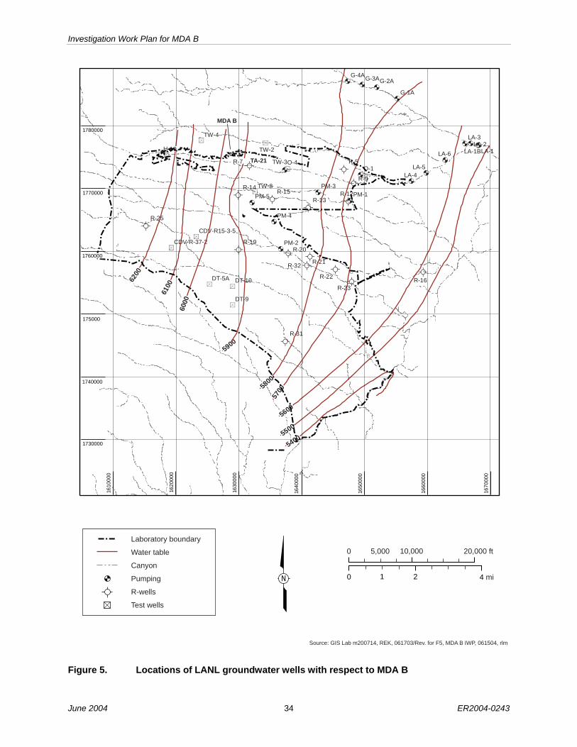
Investigation Work Plan for MDA B
June 2004 34 ER2004-0243
55005500
5700
5700
56005600
5800
5800
59005900
6100
6100
6200
6200
54005400
O-1
R-9
R-5
PM-5
PM-4
PM-3
PM-2
PM-1
G-4AG-3AG-2A
TW-8
TW-2
DT-9
R-32
R-31
R-25
R-23
R-22
R-21
R-20R-19
R-16
R-15R-14
R-13R-12
LA-6
LA-5LA-4
LA-3LA-2
LA-1
G-1A
DT-5A DT-10
LA-1B
CDV-R-37-2
CDV-R15-3-5
Source: GIS Lab m200714, REK, 061703/Rev. for F5, MDA B IWP, 061504, rlm
0 21 4 mi
20,000 ft10,0005,0000
N
Laboratory boundary
Water table
Canyon
Pumping
R-wells
Test wells
1610
000
1620
000
1630
000
1640
000
1650
000
1660
000
1670
000
1740000
1730000
1780000
1770000
175000
H-19
TW-4
O-4TW-3R-7 TA-21
6000
60
1760000
MDA B
Figure 5. Locations of LANL groundwater wells with respect to MDA B

Investigation Work Plan for MDA B
ER2004-0243 35 June 2004
Repackaging and disposal
SORT BY TYPE
Waste in
Containers
IDLH screen, check labels and describe physical
characteristics
Open, inspect, HazCat screen
contents Field screen, sample, test
IDLH screen, check labels and describe physical
characteristics
Move to outbuilding for
HazCat Screening
Rad., Haz. or Mixed Waste
Are contents safe to handle?
(Not IDLH) Describe, photo, video
Examine and Screen for IDLH Conditions
Is material safe to handle?
YES
NO
Stop work, evaluate and
modify handling
requirements
-Debris and Rubble -Classified Docs -Lab Equipment
-Other Items
Return to Excavation
Packaging and disposal
Is it high risk to future removal operations, the environment or
public?
Yes No
Chemicals in
Containers
EXCAVATE LANDFILL CONTENTS
Describe, photo, video, sample
Sample and segregate by
WAC
Sample and Segregate by WAC
Sample and segregate by
WAC
No
Yes
Are containers safe to handle?
Stop work and Notify EM&R.
- Evaluate
hazards and take appropriate
actions
-Fill Material/Soil Matrix
Field screen, sample, test
Describe, photo, video
Non-containerized Waste Zone
Materials
Packaging and disposal
Non-Rad./Non-
Haz. Waste
Yes
No
Rad., Haz or
Mixed Waste
Non-Rad/Non-
Haz. Waste
Rad., Haz or
Mixed Waste
Non-Rad/Non-
Haz. Waste
Repackaging and disposal
Rad., Haz or
Mixed Waste
Non-Rad/Non-
Haz. Waste
Describe, photo, video
Stop work, evaluate and
modify handling
requirements
Special handling
for classified
documents
Will it impede future
investigations?
Yes
Return to Excavation
No
Open, test, sample contents. Describe,
photo, video, sample
Figure 6. Decision tree detailing sorting, screening, and packaging of excavated material

Investigation Work Plan for MDA B
June 2004 36 ER2004-0243
Set Up on Excavation Location and Install
Engineering Controls
Excavate Exploratory Trench
Log Trench and Exhumed Materials
-Photo, Video, Visual Inspection, Physical Descriptions
Backfill and Compact Excavation
Backfill and Compact Potholes
Collect Samples from Underlying Tuff
IDLH Screening
Sort by Type
HAZCAT Screening
Combine Like Waste Types
Sample for WAC
Conduct Definitive ID Screening (GC, XRF, etc.)
Survey Trench Location, Features, and Dimensions
Repackage/Stabilize Waste
Manage Materials
Excavate Potholes
Demobilize from Excavation Area
Figure 7. Tentative sequence of activities for each of the eight planned excavations

Investigation Work Plan for MDA B
ER2004-0243 37 June 2004
PACKAGEDWASTESTORAGE
Office
DEFINITIVEIDENTIFICATIONFACILITY (DIF)
WasteSorting
SamplingArea
WastePackaging
Waste Staging Areas
ProposedTrench (T-1)
TemporaryEnclosurePaved Surfaces
Fences
MDA B
Disposal Trench Locations(Estimated)
DP RoadRad.
laboratory
Mobilelaboratory
Figure 8. Conceptual site layout for MDA B
Parallel trench
�T�-trench
Transecttrench
Arc trench
Figure 9. Schematic showing different excavation approaches

Investigation Work Plan for MDA B
June 2004 38 ER2004-0243
Table 1
Summary of Proposed Alternatives to NMED Order Specifications and Justification for Alternatives
Item NMED Order Specification LANL-Proposed Alternative and
Differences from Order Justification for LANL
Alternative 1 The Respondents shall conduct a survey
of the disposal units at MDA B. The Respondents shall determine the dimensions and total depth of each disposal trench, absorption bed, shaft, pit, and other unit, and the base profile, topography, low elevation point, and down-slope end of the base of each disposal trench, shaft, pit, and absorption bed.
The dimensions and base elevations of each trench, absorption bed, pit, shaft, and other unit shall be determined using as-built construction drawings and boring logs. If unavailable, ground penetrating radar, magnetic surveys, or other methods shall be used. The methods used to evaluate the pits and shafts shall be approved by the Department prior to implementation. The survey shall be completed prior to implementation of the drilling explorations under Section IV.C.2.d.iii. (Order Section IV.C.2.d.ii).
Disposal unit surveys have been performed previously. A geophysical survey to locate disposal units was performed during 1998 (see Appendix B, sections B-2.2.2 and B-4.2). Dimensions of the disposal trenches have been identified by previous geophysical study.
Direct observation and measurements of the limits of the waste-disposal trench boundaries will be used to supplement the geophysical survey previously performed.
2 The Respondents shall conduct subsurface explorations in order to obtain sufficient data to characterize the extent of contamination, and to characterize fracture density, fracture orientation, and fracture fill material or the absence of fracture fill material at MDA B. The fracture characterization of the rock formations underlying MDA B shall be completed utilizing data acquired from outcrops, cores, and downhole geophysical and video log data. A discussion of the sampling methods and potential locations for collecting rock fracture data shall be included within the required characterization work plan for MDA B. The Department, prior to field investigation and data collection activities, shall approve the methods and locations for the fracture investigation activities. (Order Section IV.C.2.d.iii)
An additional eight exploratory test trenches will extend across the waste-disposal trench, exposing bedrock for additional extent and fracture characterization. Fractures have been characterized previously through TA-21–wide geologic investigations conducted as part of the Operable Unit 1106 investigation (see Appendix B, section B-3.14). Previously installed boreholes were also logged for fractures (see Appendix B, section B-4.3.1, and Appendix D). No additional fracture characterization is planned.
Because MDA B was used as a chemical and solid waste-disposal area, fractures are less significant to subsurface transport at MDA B than at other MDAs where absorption beds exist and where millions of gal. of liquid radioactive wastes were disposed. The extent of contamination has been identified for the limited set of contaminants analyzed by the seven prior angled holes. Results from the additional sampling and expanded analytical suite at the eight exploratory trenches will be used to evaluate near-trench bedrock characteristics and contamination for a comparison with the deeper borehole data previously collected.

Investigation Work Plan for MDA B
ER2004-0243 39 June 2004
Table 1 (continued)
Item NMED Order Specification LANL-Proposed Alternative and Differences from Order
Justification for LANL Alternative
3 A minimum of eight borings shall be advanced using hollow-stem auger drilling methods where practical or other drilling methods approved by the Department. Two of the borings shall be advanced to the base of the Cerro Toledo interval. All borings shall be drilled in accordance with Section X.B of this Order. The Department, prior to drilling, shall approve the location of the borings and the drilling method (Order Section IV.C.2.d.iii, Item 1).
Seven angled boreholes were installed in 1998, in accordance with the SAP approved by the NMED (see Appendix B, section B-4.3.1). Eight test trenches will be installed through the waste to obtain samples directly below the waste-disposal trenches.
A deep borehole (Location ID 21-02523) was drilled approximately 370 ft east of MDA B at MDA V and extended 660 ft below the ground surface. Another deep borehole is planned in the area of MDA V (LANL 2004, document in process). In addition, surface exposures of the Cerro Toledo interval have been observed in Los Alamos Canyon.
The addition of sampling of the subsurface soil and tuff in the eight test trenches will supplement existing angled boreholes in determining the nature and extent of contamination from the MDA B disposal trenches.
The deep MDA V borehole and the outcrop of Cerro Toledo interval exposed on the cliff face of Los Alamos Canyon approximately 250 ft southeast of MDA B are sufficiently close to MDA B to confirm the absence of perched water at the Cerro Toledo contact.
4 Each borehole shall be characterized using geophysical logging techniques approved by the Department. (Order Section IV.C.2.d.iii, Item 2)
No new boreholes are planned.
Because no new boreholes are planned, the geophysical logging described in the Order cannot be conducted.
5 A monitoring well(s) shall be installed if groundwater (perched or regional) is encountered during drilling activities or if geophysical results indicate possible zone(s) of saturation. The wells shall be constructed in accordance with Section X of this Order. (Order Section IV.C.2.d.iii, Item 3)
No monitoring wells are planned.
Zones of saturation were not encountered in previously completed boreholes (see Appendix B, section B-4.3.1, and Appendix D) in or near MDA B. Perched water is not anticipated in the waste-disposal trenches.
6 Vapor monitoring wells shall be installed in the borings if vapor-phase contamination is detected during drilling activities. (Order Section IV.C.2.d.iii, Item 4)
No new pore-gas sampling is proposed for MDA B.
Sufficient pore-gas sampling has occurred under MDA B waste-disposal trenches. Pore-gas sampling was performed on previous boreholes per the SAP approved by the NMED. Maximum detected concentrations were less than 1 ppmv (see Appendix B, section B-4.3.1).

Investigation Work Plan for MDA B
June 2004 40 ER2004-0243
Table 1 (continued)
Item NMED Order Specification LANL-Proposed Alternative and Differences from Order
Justification for LANL Alternative
7 All borings not completed as monitoring wells (vapor or groundwater monitoring wells) shall be properly plugged and abandoned. Documentation of proper well abandonment shall be submitted to the Department within 30 days of abandonment. (Order Section IV.C.2.d.iii)
No borings are planned under this work plan. Exploratory trenches and test pits excavated through the waste will be backfilled with clean soil and/or waste excavated from the trenches, based on field decisions as described in the work plan.
Boreholes installed under the 1998 SAP were properly abandoned in accordance with SOPs. Investigation of the trenches allows contaminated waste to be returned to the exploratory trench and test-pit excavations. Clean soil or tuff will be used where test trenches or test pits extend into tuff or soil outside the waste-disposal trench limits.
8 Soil samples shall be collected continuously for the first 40 ft and at ten-ft intervals thereafter. (Order Section IV.C.2.d.iv, Item 1)
Test trenches and test pits allow for continuous sampling of the excavated soil or tuff. No new boreholes are planned.
Core samples collected under the 1998 SAP were taken at 5- and 10-ft intervals in boreholes angled beneath the trenches (see Appendix B, section B-4.3.1). Excavated soil or tuff profiles will be available for logging as material is taken from the excavations. Visual logging and field screening of the soil profile in the excavations serves the same purpose as collecting borehole samples on a continuous basis.
9 Samples shall be collected and screened in accordance with the methods described in Section IX.B of this Order. (Order Section IV.C.2.d.iv, Item 2)
Samples will be collected from the waste and underlying bedrock in a manner appropriate for the excavation of exploratory trenches. Field screening of excavated materials from exploratory trenches and test pits is planned. The screening methods specified in section 5.6 of this plan meet, or exceed, those identified in the Order.
Because exploratory trenches will be made instead of borings, the methods described in Section IX.B for sampling are not applicable.
10 A minimum of three core samples from the tuff overlying the Cerro Toledo shall be collected and submitted for laboratory permeability testing in accordance with Section IX.B of this Order. (Order Section IV.C.2.d.iv, Item 3)
No deep borehole is planned for MDA B.
A deep angled borehole is planned for MDA V and will intersect the Cerro Toledo at a horizontal distance of approximately 300 ft from MDA B. Permeability data for the tuff overlying the Cerro Toledo interval will be collected.

Investigation Work Plan for MDA B
ER2004-0243 41 June 2004
Table 1 (continued)
Item NMED Order Specification LANL-Proposed Alternative and Differences from Order
Justification for LANL Alternative
11 Field screening and laboratory sample selection shall be biased towards evidence of contamination, lithologic contacts, fractures, fracture fill material, surge beds, and other higher permeability units identified during investigation activities. The samples shall be collected and screened in accordance with the methods described in Section IX.B of this Order. (Order Section IV.C.2.d.iv, Item 4)
Samples will be collected as specified (see Table 4 and section 5.8 in this plan). The field-screening methods specified in Table 4 meet or exceed those described in the Order.
Exploratory trenches allow visual screening of subsurface features in a manner that cannot be obtained with boreholes.
12 Sediment, soil and rock samples shall, at a minimum, be obtained from each boring at the intervals described in Paragraph 1 above and from the bedrock directly below the base elevation of each absorption bed or shaft. A sample also shall be obtained at the maximum depth of each boring. (Order Section IV.C.2.d.iv, Item 5)
Samples will be collected from exploratory trenches and test pits from directly below the waste-disposal trenches and from the maximum excavation depth. Samples will also be collected in disposal trench sidewalls, where encountered.
Collecting samples of the bedrock from the exploratory trenches is comparable to obtaining samples from boreholes.
13 A minimum of four samples shall be selected from each boring for submittal to a laboratory for analysis of VOCs, SVOCs, HE, pH, PCBs, dioxins, furans, nitrates, perchlorate, TAL [target analyte list] metals, total uranium, cyanide, and radionuclides. The sample exhibiting the highest field screening detection; the sample obtained from the maximum depth in each boring that displays field screening evidence of contamination; the sample located immediately below the base of any pit, tank, or other structure; and the sample from the total boring depth shall be submitted for laboratory analysis. The Department may require that additional samples, collected from the borings, be submitted for laboratory analyses. (Order Section IV.C.2.d.iv, Item 6)
Previous analytical suites specified in EPA- and NMED-approved work plans did not include HE, pH, PCBs, dioxins, furans, nitrates, perchlorate, and cyanide.
Samples from exploratory trenches and test pits will be collected and analyzed for, as specified in the Order, pH, PCBs, HE, dioxins, furans, nitrates, perchlorate, and cyanide. At least six samples will be collected from each exploratory trench for laboratory analysis (see Table 5 in this plan).
Deeper subsurface VOC contamination was characterized using pore-gas sampling data from the 1998 angled boreholes (see section 2.2.2). HE analysis of new samples will confirm the absence of HE. HE compounds were not indicated in previous SVOC analyses (see section 2.2). Dioxins and furans have limited subsurface mobility and are most likely to be detected at, or immediately below, trench bottoms.
14 All TA-21 outfalls shall be investigated in accordance with Section IV.A.4 of this Order. The characterization of the drainages shall be included in the work plan prepared to fulfill the requirements of Section IV.A.4 of this Order. (Order Section IV.C.2.d.v)
No outfall investigation will be conducted. TA-21 outfall drainages have been characterized previously in the Phase report and addendum already submitted to the NMED (LANL 1995, 52350.1).
There are no outfalls associated with MDA B.

Investigation Work Plan for MDA B
June 2004 42 ER2004-0243
Table 1 (continued)
Item NMED Order Specification LANL-Proposed Alternative and Differences from Order
Justification for LANL Alternative
15 The Respondents shall determine if vapor-phase contamination is present beneath the site. If vapor-phase contamination is detected, the Respondents shall install vapor monitoring wells in the borings and conduct vapor monitoring and sampling as outlined in Section IX.B of this Order. In addition, the Respondents shall submit a vapor monitoring and sampling work plan for approval by the Department prior to well construction. If vapor-phase contamination is detected, the Respondents shall, at a minimum, collect vapor samples from discrete zones in each vapor monitoring well or boring at depths approved by the Department. These data will be used to evaluate the need for additional monitoring and investigation. (Order Section IV.C.2.d.vi)
No new vapor-phase testing is planned.
Pore-gas sampling was previously conducted using boreholes that were installed in accordance with the 1998 SAP approved by the NMED (see Appendix B, section B-4.3.1).
16 If intermediate zone groundwater is encountered or if geophysical or other evidence suggests the presence of intermediate perched groundwater during the required subsurface investigations for MDA B, intermediate groundwater monitoring well(s) will be required by the Department. The minimum depth of the subsurface investigations for MDA B will be the base of the Cerro Toledo interval. If groundwater is detected, these monitoring wells shall target all potential intermediate perched water bearing intervals identified during subsurface explorations at MDA B. If required, the Respondents shall include the well(s) in the TA-21 monitoring and sampling plan. (Order Section IV.C.2.d.vii)
None. The deep borehole which was completed at MDA V, near MDA B, was advanced beyond the base of the Cerro Toledo interval to a depth of 660 ft and did not encounter perched water.
Intermediate perched water was not encountered to the depth of previous investigations at MDA B. The test trenches will not reach the depths previously investigated.
17 The Respondents shall install regional groundwater monitoring wells if the Department determines the need for additional wells intersecting the regional groundwater aquifer associated with TA-21 based on investigation data. The wells shall be installed according to the requirements in Section X of this Order. (Order Section IV.C.2.d.viii)
No regional groundwater investigations will be performed as part of this work plan. Regional groundwater investigations are being conducted in accordance with the hydrogeologic work plan (LANL 1998, 59599), approved by the NMED, and “Los Alamos Canyon and Pueblo Canyon Intermediate and Regional Aquifer Groundwater Work Plan” (LANL 2003, 82612).
Installation of regional groundwater wells would duplicate the work being performed under the hydrogeologic work plan and “Los Alamos Canyon and Pueblo Canyon Intermediate and Regional Aquifer Groundwater Work Plan” (LANL 2003, 82612).

Investigation Work Plan for MDA B
ER2004-0243 43 June 2004
Table 1 (continued)
Item NMED Order Specification LANL-Proposed Alternative and Differences from Order
Justification for LANL Alternative
18 Groundwater samples shall be obtained from Los Alamos Canyon monitoring wells LAO-1.2, LAO-1.8, LAO-1.6(g), LAO-2, LAO-3A, LAO-4.5C, LAO-5, LAO-6, LAO-6A, LADP-3, R-9i, R-5, R-7, R-8, R-9, TW-3, and any wells installed in the future determined by the Department to be required and at the frequency described in Section XII of this Order. As described in Section IV.B.1.e.viii, TW-3 shall be plugged and abandoned according to the procedures in Section X.D. Groundwater shall be monitored from TW-3 until the well is properly abandoned. (Order Section IV.C.2.d.ix, Item 1)
No groundwater sampling of existing wells will be performed as part of this work plan. The wells identified in Section IV.C.2.d.ix, Item 1, of the Order will be monitored as specified in the facility-wide groundwater monitoring plan required under Section IV.A.3 of the Order.
Groundwater investigations would duplicate the work required under Section IV.A.3 of the Order.
19 The groundwater sampling shall be conducted in accordance with Section IX.B of this Order. (Order Section IV.C.2.d.ix, Item 2)
No groundwater sampling of existing wells will be performed as part of this work plan (see Item 18 above).
See Item 18 above.
20 Groundwater samples shall be collected from the Los Alamos Canyon monitoring wells for submittal to a laboratory for analysis of general chemistry parameters as described in Section IX.B of this Order, radionuclides, perchlorate, TAL metals, total uranium, cyanide, VOCs, SVOCs, HE, and for other analytes specified by the Department. (Order Section IV.C.2.d.ix, Item 3)
No groundwater sampling of existing wells will be performed as part of this work plan (see Item 18 above).
See Item 18 above.
21 As described in Section IV.B.1.d.vii, Paragraph 7, a long-term groundwater monitoring and sampling work plan shall be submitted to the Department for approval. The work plan shall include the specifics for conducting groundwater sampling at MDA B as part of the Los Alamos/Pueblo Canyon watershed prior to implementation of the groundwater-sampling program. (Order Section IV.C.2.d.ix, Item 4)
A long-term groundwater monitoring and sampling work plan will not be prepared as part of the MDA B investigation. Results of the MDA B investigation will be considered during development of the groundwater monitoring plan required under Section IV.A.3.
Development of a long-term groundwater monitoring plan for MDA B would duplicate the work required under Section IV.A.3 of the NMED Order.
Note: The “Order” referred to in this table is dated November 2002 (NMED 2002, 75910).
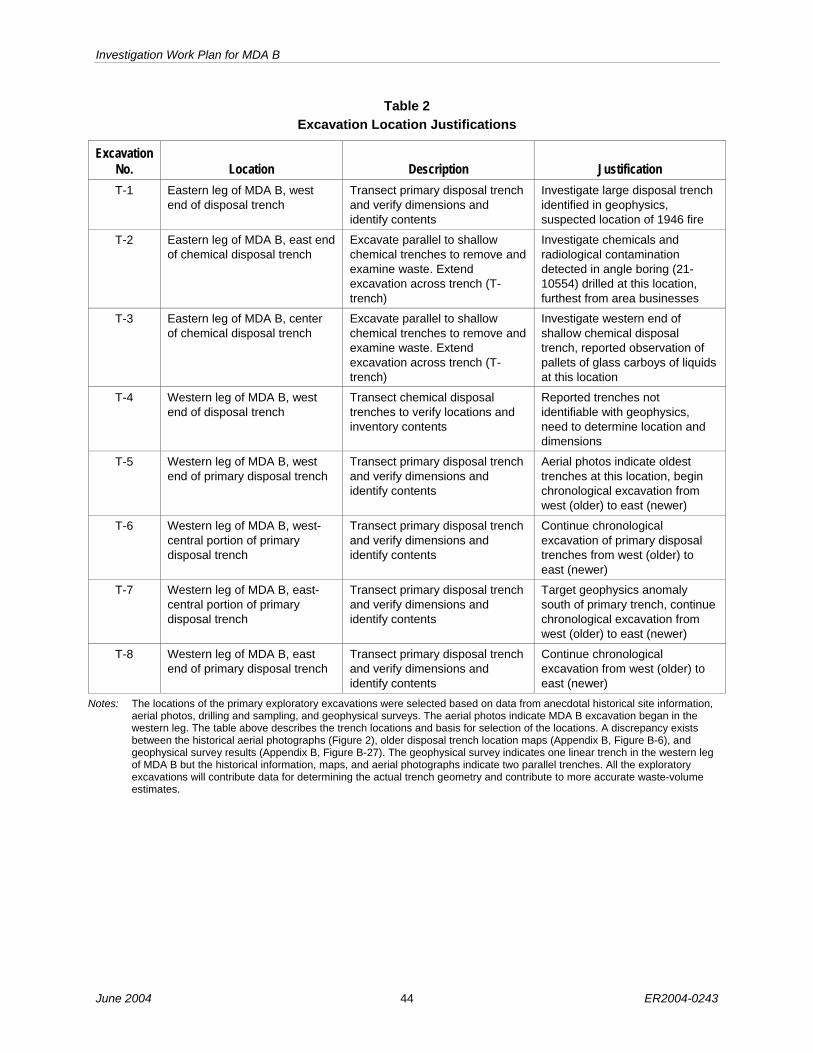
Investigation Work Plan for MDA B
June 2004 44 ER2004-0243
Table 2 Excavation Location Justifications
Excavation No. Location Description Justification T-1 Eastern leg of MDA B, west
end of disposal trench Transect primary disposal trench and verify dimensions and identify contents
Investigate large disposal trench identified in geophysics, suspected location of 1946 fire
T-2 Eastern leg of MDA B, east end of chemical disposal trench
Excavate parallel to shallow chemical trenches to remove and examine waste. Extend excavation across trench (T-trench)
Investigate chemicals and radiological contamination detected in angle boring (21-10554) drilled at this location, furthest from area businesses
T-3 Eastern leg of MDA B, center of chemical disposal trench
Excavate parallel to shallow chemical trenches to remove and examine waste. Extend excavation across trench (T-trench)
Investigate western end of shallow chemical disposal trench, reported observation of pallets of glass carboys of liquids at this location
T-4 Western leg of MDA B, west end of disposal trench
Transect chemical disposal trenches to verify locations and inventory contents
Reported trenches not identifiable with geophysics, need to determine location and dimensions
T-5 Western leg of MDA B, west end of primary disposal trench
Transect primary disposal trench and verify dimensions and identify contents
Aerial photos indicate oldest trenches at this location, begin chronological excavation from west (older) to east (newer)
T-6 Western leg of MDA B, west-central portion of primary disposal trench
Transect primary disposal trench and verify dimensions and identify contents
Continue chronological excavation of primary disposal trenches from west (older) to east (newer)
T-7 Western leg of MDA B, east-central portion of primary disposal trench
Transect primary disposal trench and verify dimensions and identify contents
Target geophysics anomaly south of primary trench, continue chronological excavation from west (older) to east (newer)
T-8 Western leg of MDA B, east end of primary disposal trench
Transect primary disposal trench and verify dimensions and identify contents
Continue chronological excavation from west (older) to east (newer)
Notes: The locations of the primary exploratory excavations were selected based on data from anecdotal historical site information, aerial photos, drilling and sampling, and geophysical surveys. The aerial photos indicate MDA B excavation began in the western leg. The table above describes the trench locations and basis for selection of the locations. A discrepancy exists between the historical aerial photographs (Figure 2), older disposal trench location maps (Appendix B, Figure B-6), and geophysical survey results (Appendix B, Figure B-27). The geophysical survey indicates one linear trench in the western leg of MDA B but the historical information, maps, and aerial photographs indicate two parallel trenches. All the exploratory excavations will contribute data for determining the actual trench geometry and contribute to more accurate waste-volume estimates.

Investigation Work Plan for MDA B
ER2004-0243 45 June 2004
Table 3 Screening Methods and Frequency for Excavations
Screening Analysis Instrument Method Order of
Performance Alpha/beta/gamma radiation
Alpha/beta/gamma radiation detector
LANL-ER-SOP-10.14 1
Pyrophoric materials Infrared thermometer Newport Model OS521 handheld
Manufacturer’s instructions
2
Gases Dräger tubes/combustible gas meter: Mine Safety Appliances model: Passport Contractor Multigas Detector
Manufacturer’s instructions
3
IDLH
VOCs Flame ionization detector (FID)/photoionization detector (PID), Foxboro model TVA-1000 PID/FID analyzer
EPA SOP #21141: photoionization detector (PID)
4
Field monitoring for surface and volume radioactivity levels
Rad meter inside a fume hood
LANL-ER-SOP-10.14 1
Physical description screening analysis in waste: color, turbidity, viscosity, physical state, layering, incidental odor
Physical observations on bench-top lab with fume hood
ASTM D4979-95 2
Compatibility of screening analysis of waste, Test Method C—Water Compatibility
Bench-top lab with hood ASTM D5058-90 3
Screening of pH in waste Indicator paper and/or a pH meter inside a bench-top lab with fume hood
ASTM D4980-89 4
Standard test methods for screening of reactive sulfides in waste
Indicator paper inside a fume hood
ASTM D4978-95 5
Flammability potential screening analysis
Open flame inside a fume hood
ASTM D4982-95 6
Screening of oxidizers in waste
Indicator paper, bench-top lab with fume hood
ASTM D4981-95 7
HazCat: handling and segregation, characterization
Screening test method for screening apparent specific gravity and bulk density of waste
Physical observation and/or hydrometer and/or a pycnometer inside a fume hood
ASTM D5057-90 8
1 EPA SOPs may be located at USEPA.gov web site.

Investigation Work Plan for MDA B
June 2004 46 ER2004-0243
Table 3 (continued)
Screening Analysis Instrument Method Order of
Performance Compatibility of screening analysis of waste, Test Method A—Commingled Waste Compatibility test method
Thermometer and physical observation inside fume hood
ASTM D5058-90 9 HazCat: handling and segregation, characterization (continued)
Screening of PCBs in soil (only performed on oily or suspect PCB-contaminated waste materials)
Immunoassay inside a fume hood
LANL-ER-SOP-10.1 10
Chemical composition/concentration
Gas chromatography EPA SOP #2107, #2108, #2109
As needed
Chemical composition/concentration
Immunoassay Manufacturer’s Instructions
As needed
Definitive identification for disposal characterization*
Chemical composition/concentration
X-ray fluorescence LANL-ER-SOP-10.08, R1
As needed
* Additional or alternate analyses may be required to meet WAC.
Table 4 Regulatory Classifications for Anticipated Waste Streams
Regulatory Classification Possible Disposal Facility Solid Waste Los Alamos County landfill
Industrial or New Mexico special waste Waste Management of Rio Rancho, NM
RCRA hazardous waste Envirocare, Utah, or appropriate off-site treatment/disposal facility via LANL, TA-54
Low-level radioactive waste LANL, TA-54
High-level radioactive waste Pending identification
Mixed low-level waste Envirocare, Utah, via LANL, TA-54
Transuranic (TRU), mixed TRU waste Waste Isolation Pilot Plant via LANL, TA-54
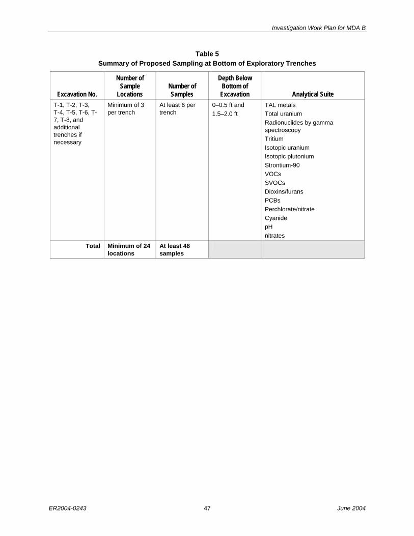
Investigation Work Plan for MDA B
ER2004-0243 47 June 2004
Table 5 Summary of Proposed Sampling at Bottom of Exploratory Trenches
Excavation No.
Number of Sample
Locations Number of Samples
Depth Below Bottom of
Excavation Analytical Suite T-1, T-2, T-3, T-4, T-5, T-6, T-7, T-8, and additional trenches if necessary
Minimum of 3 per trench
At least 6 per trench
0–0.5 ft and 1.5–2.0 ft
TAL metals Total uranium Radionuclides by gamma spectroscopy Tritium Isotopic uranium Isotopic plutonium Strontium-90 VOCs SVOCs Dioxins/furans PCBs Perchlorate/nitrate Cyanide pH nitrates
Total Minimum of 24 locations
At least 48 samples