Investigation of transverse beam instabilities in the MAX ...
15
TWIICE workshop, January 2014 Investigation of transverse beam instabilities in the MAX IV 3 GeV ring using the multibunch code mbtrack Marit Klein Galina Skripka, Ryutaro Nagaoka, Pedro F. Tavares
Transcript of Investigation of transverse beam instabilities in the MAX ...

TWIICE workshop, January 2014
Investigation of transverse beam instabilities in the MAX IV 3 GeV ring using the multibunch code mbtrack
Marit Klein
Galina Skripka, Ryutaro Nagaoka, Pedro F. Tavares
[email protected] workshop, January 2014
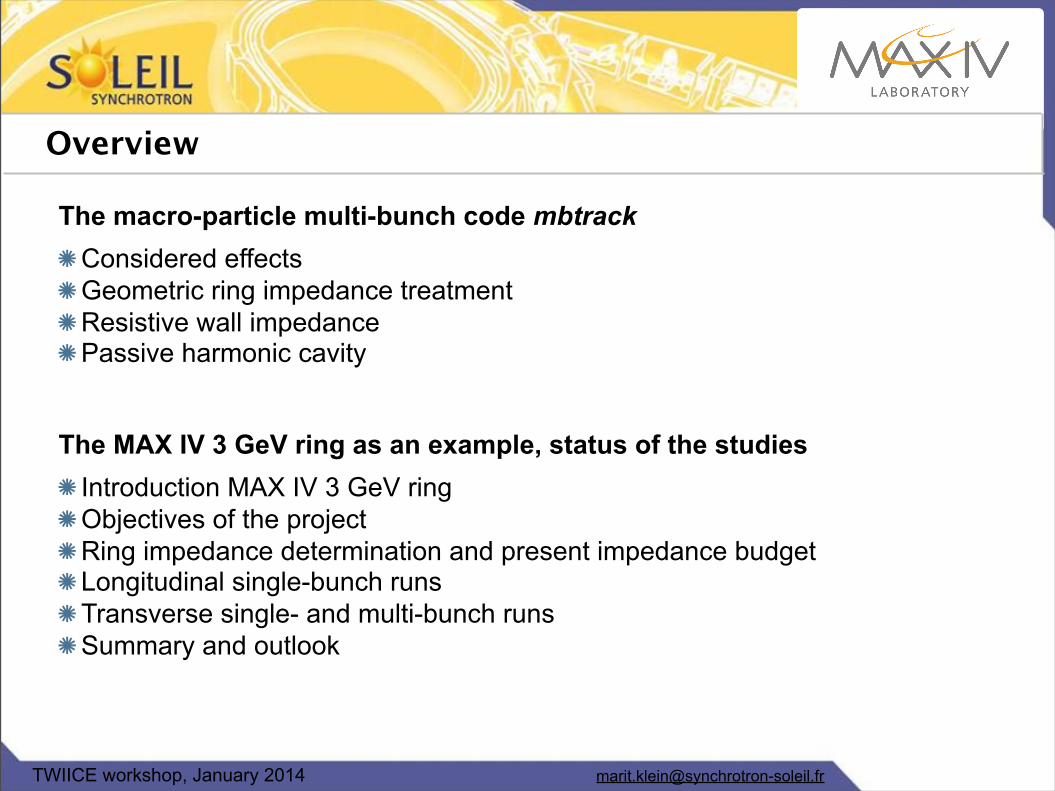
Overview
The macro-particle multi-bunch code mbtrackConsidered effectsGeometric ring impedance treatmentResistive wall impedancePassive harmonic cavity
The MAX IV 3 GeV ring as an example, status of the studiesIntroduction MAX IV 3 GeV ringObjectives of the projectRing impedance determination and present impedance budgetLongitudinal single-bunch runsTransverse single- and multi-bunch runsSummary and outlook

[email protected] workshop, January 2014
The macro-particle multi-bunch code mbtrack
6D macroparticle tracking code for multiple bunchesinternal motions and micro-structures can be followedallows for an arbitrary filling pattern
Single- (Intra-) bunch effects: geometric ring impedance, wall resistivityQuantum excitation and radiation dampingMulti- (Inter-) bunch effects:
transverse resistive wall impedance, passive harmonic cavity (HC)Multiple active (powered) cavities possible Damping from gradient dipoles + insertion device radiation lossesCurrent scans: Bunch length, energy spread, trans. beam sizeIon-beam interaction and transverse feedbackParallelized code:
Master task: organizes the data exchange by MPI Slave tasks: each corresponding to one present bunch

[email protected] workshop, January 2014
Geometric ring impedance & wall resistivity
Goal: Treat numerically computed wakes (as single bunch effect)
Impedance inputs:Series of resonators, broad- or narrow-bandAdditional purely resistive componentsAdditional purely inductive componentsResistive wall contribution: round pipe, radius a, conductivity σ
Determination of the self-field:Determination of Green‘s functionsLongitudinal binning and smoothening of distributionTransverse determination of dipole moment per binCalculation of effects per longitudinal bin
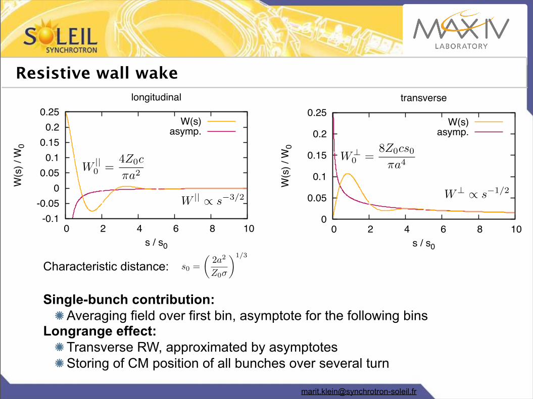
Resistive wall wake
Characteristic distance:
Single-bunch contribution: Averaging field over first bin, asymptote for the following bins
Longrange effect:Transverse RW, approximated by asymptotesStoring of CM position of all bunches over several turn
s0 =
✓2a2
Z0�
◆1/3
0
0.05
0.1
0.15
0.2
0.25
0 2 4 6 8 10
W(s
) / W
0
s / s0
transverse
asymp.W(s)
-0.1-0.05
0 0.05
0.1 0.15
0.2 0.25
0 2 4 6 8 10
W(s
) / W
0
s / s0
longitudinal
asymp.W(s)
W ||0 =
4Z0c
⇡a2W?
0 =8Z0cs0⇡a4
W || / s�3/2 W? / s�1/2

Passive harmonic cavity: Phasor scheme
Beam voltage of the passive HC as phasor Ṽ:
Update phasor after every binActual voltage in HC is the real part of Ṽ
(Scheme not possible for RW, no exponential decay)
k = !rR/2Qrotation decay induction
˜Vj+1 =
˜Vj exp [(i!r � (!r/2Q))�t]� 2kqj�t = tj+1 � tj
-0.3-0.25
-0.2-0.15
-0.1-0.05
0 0.05
0.1 0.15
0.2 0.25
-1.5 -1 -0.5 0 0.5 1 1.5
V(o)
, l(o
), (a
.u.)
long. pos. / ns
charge densityVrf-Urad/e
VHCVrf + VHC - Urad/e 0
20 40 60 80
100 120 140 160 180 200
-0.6 -0.4 -0.2 0 0.2 0.4 0.6 0.8
num
ber o
f par
ticle
s
long. pos. / ns
quarticturn 0
turn 60,000
J. M. Byrd et al., Phys. Rev. ST Accel. Beams 5, 092001 (2002)
[email protected] workshop, January 2014
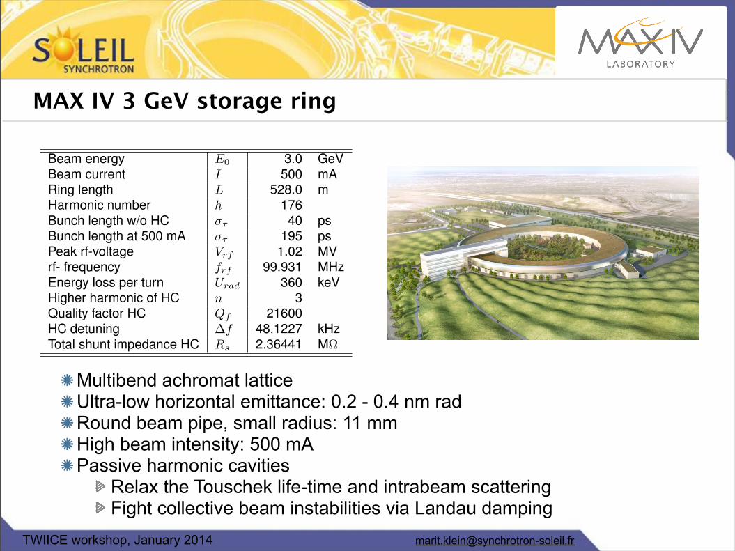
MAX IV 3 GeV storage ring
Multibend achromat latticeUltra-low horizontal emittance: 0.2 - 0.4 nm radRound beam pipe, small radius: 11 mmHigh beam intensity: 500 mAPassive harmonic cavities
Relax the Touschek life-time and intrabeam scatteringFight collective beam instabilities via Landau damping
Beam energy E0 3.0 GeVBeam current I 500 mARing length L 528.0 mHarmonic number h 176Bunch length w/o HC �⌧ 40 psBunch length at 500 mA �⌧ 195 psPeak rf-voltage Vrf 1.02 MVrf- frequency frf 99.931 MHzEnergy loss per turn Urad 360 keVHigher harmonic of HC n 3Quality factor HC Qf 21600HC detuning �f 48.1227 kHzTotal shunt impedance HC Rs 2.36441 M⌦

[email protected] workshop, January 2014
Planned Studies
Major Objectives of the Studies:Verification of no critical impedance issues related to beam instabilitiesEvaluation of single bunch and multibunch instability thresholdsSpecial efforts to be made in tracking simulations in order to use the
whole of numerically evaluated (GdfidL) wake fields and incorporate the effect of harmonic cavities (transient effects)
Single bunch tracking:Are all instability thresholds well above the nominal bunch current?Microwave instability in the longitudinal planeTMCI and head-tail instabilities in the transverse plane
Multibunch tracking:Can we overcome resistive-wall instabilities with Landau cavities and
chromaticity shifting?Inclusion of both resistive-wall and broadband impedancesSimulation of harmonic cavity effects
[email protected] workshop, January 2014
0
50
100
150
200
250
300
0 5 10 15 20 25 30
YIm
Z x (k
Ohm
/m)
frequency (GHz)
CavitiesBPMs+flanges
VC1+VC2+VC8pingerother
0
20
40
60
80
100
120
140
0 5 10 15 20 25 30Y
ImZ y
(kO
hm/m
)
frequency (GHz)
CavitiesBPMs+flanges
VC1+VC2+VC8pingerother
0
50
100
150
200
250
0 5 10 15 20 25 30
YR
eZx (
kOhm
/m)
frequency (GHz)
CavitiesBPMs+flanges
VC1+VC2+VC8pingerother
0
10
20
30
40
50
60
70
0 5 10 15 20 25 30
YR
eZy (
kOhm
/m)
frequency (GHz)
CavitiesBPMs+flanges
VC1+VC2+VC8pingerother
0
100
200
5 10 15 20 25 30
Im(Z
L/n)
(mO
hm)
frequency (GHz)
CavitiesBPMs+flanges
Tapersother
100
200
5 10 15 20 25 30
Re(
Z L/n
) (m
Ohm
)
frequency (GHz)
CavitiesBPMs+flanges
Tapersother
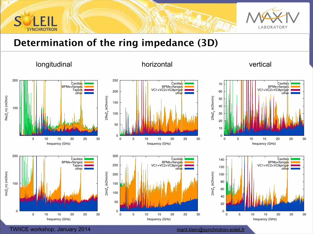
Determination of the ring impedance (3D)
longitudinal verticalhorizontal
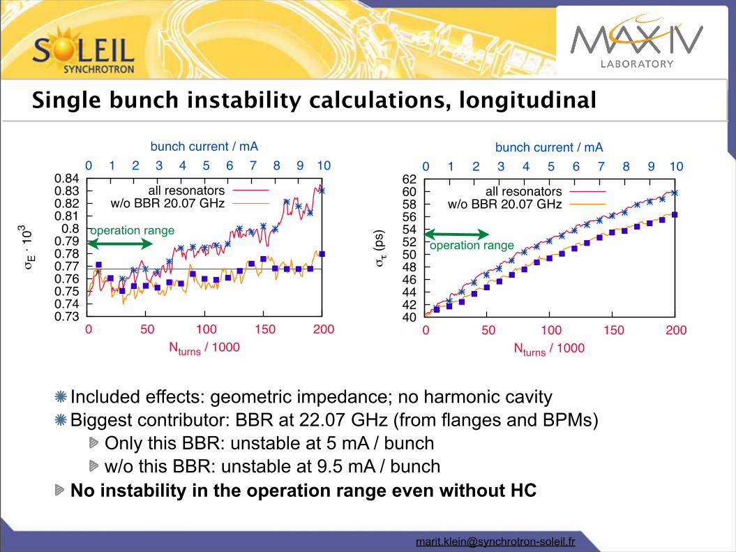
Single bunch instability calculations, longitudinal
Included effects: geometric impedance; no harmonic cavityBiggest contributor: BBR at 22.07 GHz (from flanges and BPMs)
Only this BBR: unstable at 5 mA / bunchw/o this BBR: unstable at 9.5 mA / bunch
No instability in the operation range even without HC
40 42 44 46 48 50 52 54 56 58 60 62
0 50 100 150 200
0 1 2 3 4 5 6 7 8 9 10
mo (
ps)
Nturns / 1000
bunch current / mA
all resonatorsw/o BBR 20.07 GHz
0.73 0.74 0.75 0.76 0.77 0.78 0.79
0.8 0.81 0.82 0.83 0.84
0 50 100 150 200
0 1 2 3 4 5 6 7 8 9 10
mE u 1
03
Nturns / 1000
bunch current / mA
all resonatorsw/o BBR 20.07 GHz
operation rangeoperation range
[email protected] workshop, January 2014
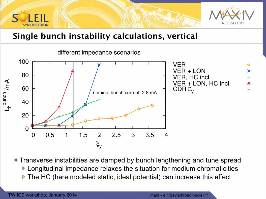
Single bunch instability calculations, vertical
Transverse instabilities are damped by bunch lengthening and tune spreadLongitudinal impedance relaxes the situation for medium chromaticitiesThe HC (here modeled static, ideal potential) can increase this effect
0
20
40
60
80
100
0 0.5 1 1.5 2 2.5 3 3.5 4
I thbu
nch /m
A
jy
different impedance scenarios
VERVER + LONVER, HC incl.VER + LON, HC incl.CDR jynominal bunch current: 2.8 mA

[email protected] workshop, January 2014
Multi-bunch calculations: Resistive wall impedance
CM history of each bunch stored in an arrayResulting effect is supposed to be the same for all particles in one bunch
Growth rates of beam size can be determined from monitored emittanceGrowth rates depend on history length
turn
-0.6
-0.4
-0.2
0
0.2
0.4
0.6
0 20 40 60 80 100 120 140 160
dipo
le m
om.
bucket
-5-4.5-4-3.5-3-2.5-2-1.5-1
1e-07
1e-06
1e-05
0.0001
0.001
0.01
0.1
1
10
100
0 1 2 3 4 5 6 7
emitt
ance
time / ms
N(hist): 3, rate: 1.2955N(hist): 5, rate: 1.6091N(hist): 10, rate: 1.3421N(hist): 15, rate: 1.6459N(hist): 20, rate: 1.4106N(hist): 25, rate: 1.5184N(hist): 30, rate: 1.5499N(hist): 35, rate: 1.4146N(hist): 40, rate: 1.5884N(hist): 45, rate: 1.4440N(hist): 50, rate: 1.5107N(hist): 55, rate: 1.5382N(hist): 60, rate: 1.4359

[email protected] workshop, January 2014
Growth rates as function of history length:
Effect at MAX IV 10 times longer as expected
Reasons under investigation
0.95 1
1.05 1.1
1.15 1.2
1.25 1.3
1.35 1.4
1.45
0 10 20 30 40 50
grow
th ra
te (1
/ms)
considered turns
SOLEIL
1.25 1.3
1.35 1.4
1.45 1.5
1.55 1.6
1.65
0 50 100 150 200
grow
th ra
te (1
/ms)
considered turns
Qv = .28Qv = .3
MAX IV vertical
0.74
0.745
0.75
0.755
0.76
0.765
0.77
0 50 100 150 200
grow
th ra
te (1
/ms)
considered turns
MAX IV horizontal
Multi-bunch calculations: Resistive wall impedance

[email protected] workshop, January 2014
Multi-bunch calculations: Resistive wall impedance
10-15
10-14
10-13
10-12
10-11
10-10
0 10 20 30 40 50 60 70
emitt
ance
1000 turns
500 mA, passive HC and geom. imp.
Timeconsuming runs due to long damping times
Harmonic cavity tuning for maximum bunch lengthening needed
Vertical geom. impedance helps relaxing the situation
Passive HC allows operation at the nominal 500 mA
10-15
10-14
10-13
10-12
10-11
10-10
0 100 200 300 400 500
emitt
ance
current (mA)
nominal (= 1.2) chromaticity
static HC, LON + VER imp.static HC, no imp.no HC
nominal beam current: 500 mA
[email protected] workshop, January 2014
Conclusion and outlook MAX IV
Longitudinal & transverse impedance budget was determined
Longitudinal instability studies finishedNo energy spread blow-up was observed in the planned operating current range
Transverse beam instabilities studies launched
Single bunch effects (vertical):Chromaticity shifting and HC leads to sufficiently hight instability thresholds in the vertical plane
Multi-bunch effect of the wall resitivity (vertical):Very longlasting effect (100-200 turns), reason under investigationThe presence of the the geometric impedance and the HC allow stable operation at the aimed beam current (500 mA)
Studies of the horizontal plane are to come