Investigation of Multiharmonic Effects in a Single Stage ...
10
INVESTIGATION OF MULTIHARMONIC EFFECTS IN A SINGLE STAGE HIGH SPEED COMPRESSOR M. Amer, N. Maroldt, J. Seume, Institut f¨ ur Turbomaschinen und Fluid-Dynamik, Leibniz Universit ¨ at Hannover, An der Universit¨ at 1, 30823 Garbsen, Germany Abstract Multistage effects in turbomachines can lead to multiresonance phenomena where multiple eigenfrequencies are excited at the same time. In turn, these multiresonance phenomena can result in high amplitude blade vibrations and other as yet uninvestigated phenomena. This results in a shorter fatigue life, and therefore their investigation is of great importance in the prevention of structural failure. Multistage effects result from the reciprocal influence of multiple stages on each other. Multiresonance, a simultaneous excitation of at least two modes, can arise due to different blade numbers in the stages which then lead to an excitation of multiple modes through different engine orders, resulting from the interaction of the number of blades and vanes, simultaneously. To study multistage effects on the vibrational behavior of compressor blisks, a simplified setup is chosen where a single stage blisk is excited by adjustable inlet guide vanes. The multiple stages are represented by changing the angle of attack of each individual vane. This allows the multistage effect to be imitated using adjustable inlet guide vanes. The effect on the blade vibration is measured with a tip timing system. Two major objectives are pursued: firstly, the excitation of two different engine orders, ideally simultaneously, and secondly, the investigation of multistage effects which lead to multiresonance. Keywords blisk, compressor, multiharmonic excitation, multistage, engine order, tip timing 1. INTRODUCTION The prediction of a blade integrated disks (blisks) vibrational behavior is of great interest to ensure safe operation. Blisks are used in turbomachin- ery as they offer light weight compared to conven- tional rotors with a bladed disk. The research on blisks is of interest as the blades are character- ized by low mechanical damping, which explains why they are easily excited when aerodamping is not present. Early investigations such as Capece et al. [3] showed the relevance of multistage effects as they investigated a three-stage compressor to characterize the interaction between blade rows excited by aerodynamic effects. They showed that the forcing function is influenced by multiple stages. Murray et al. [8] investigated resonance crossings due to multiple stages of a compres- sor. They underlined the importance of experi- mental validation to prove the reliability of numer- ical tools. The three-stage compressor configu- ration served as test rig for their experiments in which the first torsional mode was excited and investigated. The necessity of these investiga- tions was also mentioned in connection with ris- ing loads and an increasing demand for blisks in industrial applications. The forced response ef- fects were captured by tip timing which will be also used in this work. Experiments are always necessary because they indicate mistuning effects which belong to real system behavior but cannot always be captured by numerical methods. Mistuning describes the deviation from a perfectly symmetric structure and has two main effects in turbomachinery [5]. 1 Deutscher Luft- und Raumfahrtkongress 2019 DocumentID: 490212 ©2020 doi:10.25967/490212
Transcript of Investigation of Multiharmonic Effects in a Single Stage ...

INVESTIGATION OF MULTIHARMONIC EFFECTS IN A SINGLESTAGE HIGH SPEED COMPRESSOR
M. Amer, N. Maroldt, J. Seume, Institut fur Turbomaschinen und Fluid-Dynamik, LeibnizUniversitat Hannover, An der Universitat 1, 30823 Garbsen, Germany
Abstract
Multistage effects in turbomachines can lead to multiresonance phenomena where multipleeigenfrequencies are excited at the same time. In turn, these multiresonance phenomenacan result in high amplitude blade vibrations and other as yet uninvestigated phenomena.This results in a shorter fatigue life, and therefore their investigation is of great importancein the prevention of structural failure. Multistage effects result from the reciprocal influenceof multiple stages on each other. Multiresonance, a simultaneous excitation of at leasttwo modes, can arise due to different blade numbers in the stages which then lead to anexcitation of multiple modes through different engine orders, resulting from the interactionof the number of blades and vanes, simultaneously. To study multistage effects on thevibrational behavior of compressor blisks, a simplified setup is chosen where a single stageblisk is excited by adjustable inlet guide vanes. The multiple stages are represented bychanging the angle of attack of each individual vane. This allows the multistage effect to beimitated using adjustable inlet guide vanes. The effect on the blade vibration is measuredwith a tip timing system. Two major objectives are pursued: firstly, the excitation of twodifferent engine orders, ideally simultaneously, and secondly, the investigation of multistageeffects which lead to multiresonance.
Keywords
blisk, compressor, multiharmonic excitation, multistage, engine order, tip timing
1. INTRODUCTION
The prediction of a blade integrated disks (blisks)vibrational behavior is of great interest to ensuresafe operation. Blisks are used in turbomachin-ery as they offer light weight compared to conven-tional rotors with a bladed disk. The research onblisks is of interest as the blades are character-ized by low mechanical damping, which explainswhy they are easily excited when aerodamping isnot present.Early investigations such as Capece et al. [3]showed the relevance of multistage effects asthey investigated a three-stage compressor tocharacterize the interaction between blade rowsexcited by aerodynamic effects. They showedthat the forcing function is influenced by multiplestages. Murray et al. [8] investigated resonance
crossings due to multiple stages of a compres-sor. They underlined the importance of experi-mental validation to prove the reliability of numer-ical tools. The three-stage compressor configu-ration served as test rig for their experiments inwhich the first torsional mode was excited andinvestigated. The necessity of these investiga-tions was also mentioned in connection with ris-ing loads and an increasing demand for blisks inindustrial applications. The forced response ef-fects were captured by tip timing which will bealso used in this work.Experiments are always necessary because theyindicate mistuning effects which belong to realsystem behavior but cannot always be capturedby numerical methods. Mistuning describes thedeviation from a perfectly symmetric structureand has two main effects in turbomachinery [5].
1
Deutscher Luft- und Raumfahrtkongress 2019DocumentID: 490212
©2020 doi:10.25967/490212
Firstly it changes the air flow and secondly ithas an influence on eigenfrequencies and modeshapes. The first effect results from changes inthe tip leackage flow and shock position. In turn,this has an impact on the second effect as thedescribed changes cause different pressure fluc-tuations. The pressure fluctuations have an im-pact on the aerodynamic damping which leads toshifted eigenfrequencies. These two effects canalso have an impact on the lifespan of the wholeengine. The low number of existing data setsin the literature emphasizes the need for moreaccessible research on this topic. Researcherssuch as Besem et al. [1] conducted a test se-ries and gained a large experimental data set onforced response investigations analyzing singleresonance phenomena. Their contribution aimedat answering the unsolved questions in turboma-chinery including unsteady effects such as forcedresponse and flutter. They showed that decou-pled consideration of several stages is not accu-rate enough and that the influence of downstreamstators is underestimated. Again, mistuning ef-fects were considered and their influence wascompared in experimental and numerical data.Li et al. [7] showed that the influence of the up-stream stator is still the dominant reason for thevibrational behavior of the blades. They high-lighted the lack of understanding concerning mul-tiple stage interactions.Heller et al. [4] also used tip timing measure-ments to characterize blade vibrational behav-ior in turbomachines which additionally under-lines the strength of this measurement technique.Multiharmonic vibration data was captured andmodal parameters were determined with a novelglobal optimization technique.Bladh et al. [2] investigated multistage coupling ofbladed disks. They underlined the necessity foraccurate treatment of interstage effects. Thesemultistage effects can result in changed modalblade-disk interaction. Mistuning effects werealso considered in these investigations. Theysuggested taking multiple stages into accountwhen the excitation frequency is close to eigen-frequencies.Recent literature on multistage effects thus fo-cuses on structural mechanics and aerodynamicdisturbances from upstream vanes and rotorstages leading to forced response in compres-
sors. Multiresonance, however, has yet not beeninvestigated. The investigation in the presentwork therefore focuses on two objectives:
1. Multiharmonic excitation – excitation of twoengine orders (EO) in a speed range assmall as possible
2. Multiresonance – simultaneous excitation oftwo modes
2. METHOD
2.1. Multiharmonic excitation
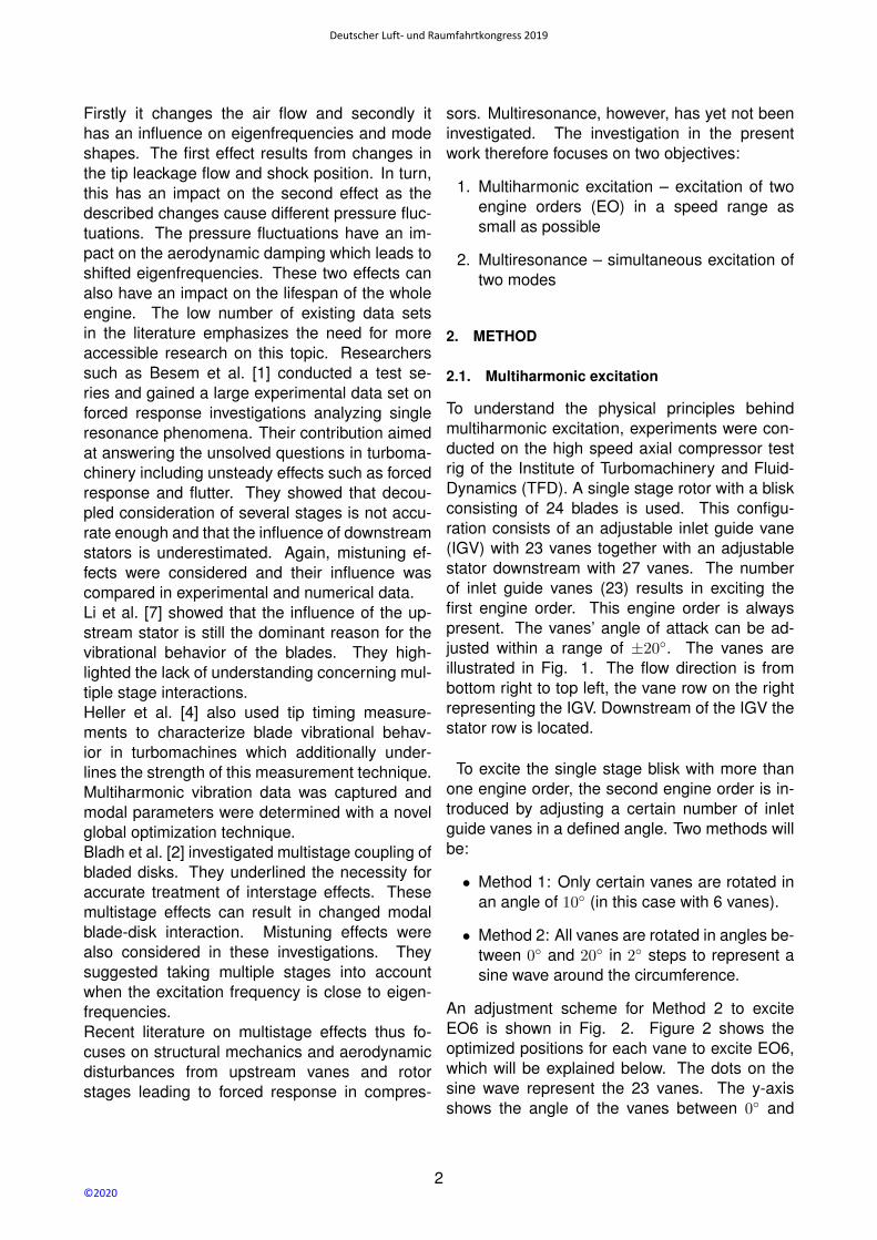
To understand the physical principles behindmultiharmonic excitation, experiments were con-ducted on the high speed axial compressor testrig of the Institute of Turbomachinery and Fluid-Dynamics (TFD). A single stage rotor with a bliskconsisting of 24 blades is used. This configu-ration consists of an adjustable inlet guide vane(IGV) with 23 vanes together with an adjustablestator downstream with 27 vanes. The numberof inlet guide vanes (23) results in exciting thefirst engine order. This engine order is alwayspresent. The vanes’ angle of attack can be ad-justed within a range of ±20◦. The vanes areillustrated in Fig. 1. The flow direction is frombottom right to top left, the vane row on the rightrepresenting the IGV. Downstream of the IGV thestator row is located.
To excite the single stage blisk with more thanone engine order, the second engine order is in-troduced by adjusting a certain number of inletguide vanes in a defined angle. Two methods willbe:
• Method 1: Only certain vanes are rotated inan angle of 10◦ (in this case with 6 vanes).
• Method 2: All vanes are rotated in angles be-tween 0◦ and 20◦ in 2◦ steps to represent asine wave around the circumference.
An adjustment scheme for Method 2 to exciteEO6 is shown in Fig. 2. Figure 2 shows theoptimized positions for each vane to excite EO6,which will be explained below. The dots on thesine wave represent the 23 vanes. The y-axisshows the angle of the vanes between 0◦ and
2
Deutscher Luft- und Raumfahrtkongress 2019
©2020
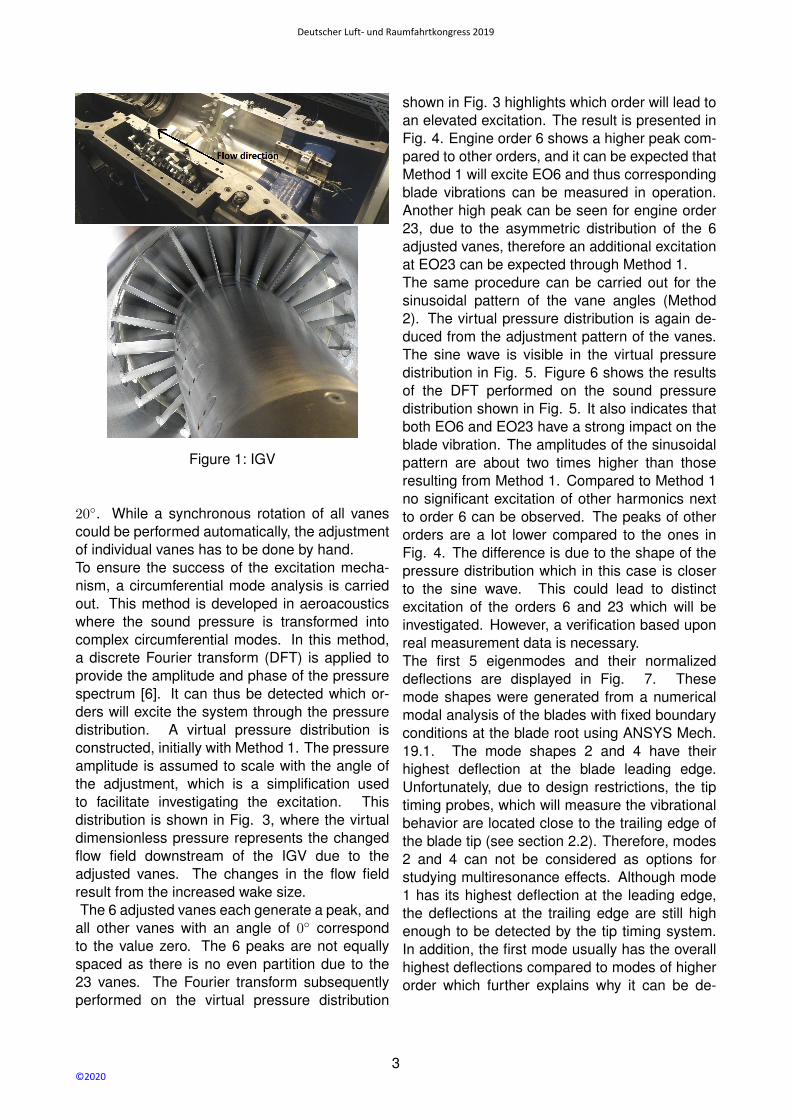
Figure 1: IGV
20◦. While a synchronous rotation of all vanescould be performed automatically, the adjustmentof individual vanes has to be done by hand.To ensure the success of the excitation mecha-nism, a circumferential mode analysis is carriedout. This method is developed in aeroacousticswhere the sound pressure is transformed intocomplex circumferential modes. In this method,a discrete Fourier transform (DFT) is applied toprovide the amplitude and phase of the pressurespectrum [6]. It can thus be detected which or-ders will excite the system through the pressuredistribution. A virtual pressure distribution isconstructed, initially with Method 1. The pressureamplitude is assumed to scale with the angle ofthe adjustment, which is a simplification usedto facilitate investigating the excitation. Thisdistribution is shown in Fig. 3, where the virtualdimensionless pressure represents the changedflow field downstream of the IGV due to theadjusted vanes. The changes in the flow fieldresult from the increased wake size.The 6 adjusted vanes each generate a peak, and
all other vanes with an angle of 0◦ correspondto the value zero. The 6 peaks are not equallyspaced as there is no even partition due to the23 vanes. The Fourier transform subsequentlyperformed on the virtual pressure distribution
shown in Fig. 3 highlights which order will lead toan elevated excitation. The result is presented inFig. 4. Engine order 6 shows a higher peak com-pared to other orders, and it can be expected thatMethod 1 will excite EO6 and thus correspondingblade vibrations can be measured in operation.Another high peak can be seen for engine order23, due to the asymmetric distribution of the 6adjusted vanes, therefore an additional excitationat EO23 can be expected through Method 1.The same procedure can be carried out for thesinusoidal pattern of the vane angles (Method2). The virtual pressure distribution is again de-duced from the adjustment pattern of the vanes.The sine wave is visible in the virtual pressuredistribution in Fig. 5. Figure 6 shows the resultsof the DFT performed on the sound pressuredistribution shown in Fig. 5. It also indicates thatboth EO6 and EO23 have a strong impact on theblade vibration. The amplitudes of the sinusoidalpattern are about two times higher than thoseresulting from Method 1. Compared to Method 1no significant excitation of other harmonics nextto order 6 can be observed. The peaks of otherorders are a lot lower compared to the ones inFig. 4. The difference is due to the shape of thepressure distribution which in this case is closerto the sine wave. This could lead to distinctexcitation of the orders 6 and 23 which will beinvestigated. However, a verification based uponreal measurement data is necessary.The first 5 eigenmodes and their normalizeddeflections are displayed in Fig. 7. Thesemode shapes were generated from a numericalmodal analysis of the blades with fixed boundaryconditions at the blade root using ANSYS Mech.19.1. The mode shapes 2 and 4 have theirhighest deflection at the blade leading edge.Unfortunately, due to design restrictions, the tiptiming probes, which will measure the vibrationalbehavior are located close to the trailing edge ofthe blade tip (see section 2.2). Therefore, modes2 and 4 can not be considered as options forstudying multiresonance effects. Although mode1 has its highest deflection at the leading edge,the deflections at the trailing edge are still highenough to be detected by the tip timing system.In addition, the first mode usually has the overallhighest deflections compared to modes of higherorder which further explains why it can be de-
3
Deutscher Luft- und Raumfahrtkongress 2019
©2020

Figure 2: Optimized positions for each vane (Method 2)
Figure 3: Virtual dimensionless pressure distribution for Method 1
Figure 4: Circumferential mode analysis of Method 1
tected properly. Mode 1 is easily excited by thesystem and small environmental disturbancesand as such, it serves well as an eigenmodebeing part of the multiresonance effect. Modeshigher than eigenmode 5 are not considered
below as their maximum amplitude is presumedto be within the measurement uncertainty of thetip timing system, and thus can not be properlydetected.The Campbell diagram of the blisk is shown
4
Deutscher Luft- und Raumfahrtkongress 2019
©2020

Figure 5: Virtual dimensionless pressure distribution for Method 2
Figure 6: Circumferential mode analysis of Method 2
in Fig. 8. By means of this diagram it can bedetected, where two engine orders lead to mul-tiresonance. According to the explanation above,the focus will be on the excitation of modes 1, 3,and 5. The objective of analyzing the Campbelldiagram is to find theoretical rotational speedswhere two different modes have an intersectionpoint with EO23 and another one below 23. Thesecond engine order has to be smaller than 23 asthe set up provides only 23 inlet guide vanes. Arotational speed found from this analysis shouldlead to multiresonance in operation. The resultsof this first analysis are shown by the dashedgreen lines in the Campbell diagram 8. TheCampbell diagram is derived from modal analysisdata of the blisks’ full cyclic model. The firstpossible rotational speed is determined as 6615rpm, where mode 1 excited by EO6 and mode3 excited by EO23 can lead to multiharmonic
excitation. The second option for multiharmonicexcitation is found at 14870 rpm where mode1 is excited by EO3 and mode 5 by EO23.These two options are summarized in table 1.
1. EO 1. Mode 2. EO 2. Mode ∆f
6 1 23 3 46.5 Hz
3 1 23 5 39 Hz
Table 1: Options of multiharmonic excitation
It must be acknowledged that nonetheless thereis a deviation between the frequencies of the pre-dicted and experimentally observed resonancepeak. The difference between the resonancepeak of mode 1 and mode 3 is 46.5 Hz, the dif-ference between the resonance peak of mode 1and mode 5 is 39 Hz. Before conducting the ex-
5
Deutscher Luft- und Raumfahrtkongress 2019
©2020

Figure 7: Mode shapes 1 - 5
periments it is not known how the vibrational be-havior is influenced by real flow conditions andhow the fading curve of each resonance will lookresulting in a maximum range where two modesare still excitable simultaneously. This mainly de-pends on the max. amplitude and the damping ofthe excited mode. The options in Table 1 result ina testing schedule with two operating points con-sidered in the experiments. Below the first optionwith EO6 and EO23 will be explored. To investi-gate this point of interest, engine order 6 needsto be physically present in the system. Method 1is applied with six vanes adjusted with an angleof 10◦. The adjustment scheme for Method 2 canbe extracted from Fig. 2.
2.2. Instrumentation and data acquisition
To perform the measurements, a tip timing sys-tem by Agilis is used. It consists of eight laserprobes, mounted in the casing pointing to the ro-tor blade trailing edge. These tip timing probesmeasure the time of arrival (TOA) of each blade.The TOA is a reference for the delay of the bladedue to blade vibration. Knowing the TOA and thecircumferential position of the probes, as well as agiven Campbell diagram allows the excited eigen-mode to be calculated, as well as other importantparameters like aerodamping.Transients are being carried out in operation ofthe axial compressor to collect the essential datawith the measurement system. The transient op-erational behavior is necessary in order to cap-ture the forced response effects. For this purposethe rotational speed is increased slowly duringthe measurement. From the transient curves, theresonance effects can be derived. They occur atthe amplitude peaks shown in Fig. 9. The ampli-tudes are visible because they are present next tothe rotational speed regions where no mode ex-citation is taking place. These transients can takeplace in a range of 3000 rpm up to the nominalspeed of 17100 rpm.
3. RESULTS
To study the effect of multiharmonic excitation,the tip timing results are analyzed. Fig. 9 displaysthe amplitude of each rotor blade detected by anexemplary tip timing probe. It captures a tran-
6
Deutscher Luft- und Raumfahrtkongress 2019
©2020

Figure 8: Campbell diagram
sient speed line starting approximately with 6000rpm running up to 6700 rpm. The increase in ro-tational speed is shown by the red straight line.The blade deflection is displayed over time re-spectively increasing rotational speed. The anal-
Figure 9: Deflection of each rotor blade (supple-mentary excitation of EO6)
ysis of Fig. 9 results in two clear peaks. The firsthigher and broader peak belongs to EO6 excitingmode 1 and is displayed at approximately 6136rpm. The second peak belongs to EO23 excit-ing mode 3 at approximately 6634 rpm. Fig. 9already shows that the second objective of excit-
ing two modes simultaneously is not achieved atthis operating point. The two resonance peaksare too far away from each other and no overlapbetween mode 1 and mode 3 can be observed.For further analysis, the averaged blade ampli-tudes are displayed in the Campbell diagram inFig. 10. The results are calculated for EO6 andEO23 using the least-square fit model. The first4 modes are illustrated by gray straight lines overa rotational speed range between 6000 and 7000rpm. The green curve fitted over the mode dis-plays the blade deflection. The green color corre-sponds to a good data fit of approximately 100 %with respect to a model of EO6 fitted into the databy the analysis algorithm and EO23 for mode 3respectively shows what frequency distance be-tween two peaks is still within acceptable boundsto detect multiharmonic excitation. The differencein frequency between a first significant increaseof the amplitude and the peak of mode 1 is ap-prox. 15 Hz. The same applies to the distancebetween peak and end of the fading curve as theresonance behavior is nearly symmetric. The de-viation of the peaks belonging to mode 3 is ap-prox. 12 Hz. Unfortunately, the calculated differ-ence between those two resonance peaks thus isapproximately 3 times higher than the acceptablemaximum allowable deviation previously identi-
7
Deutscher Luft- und Raumfahrtkongress 2019
©2020
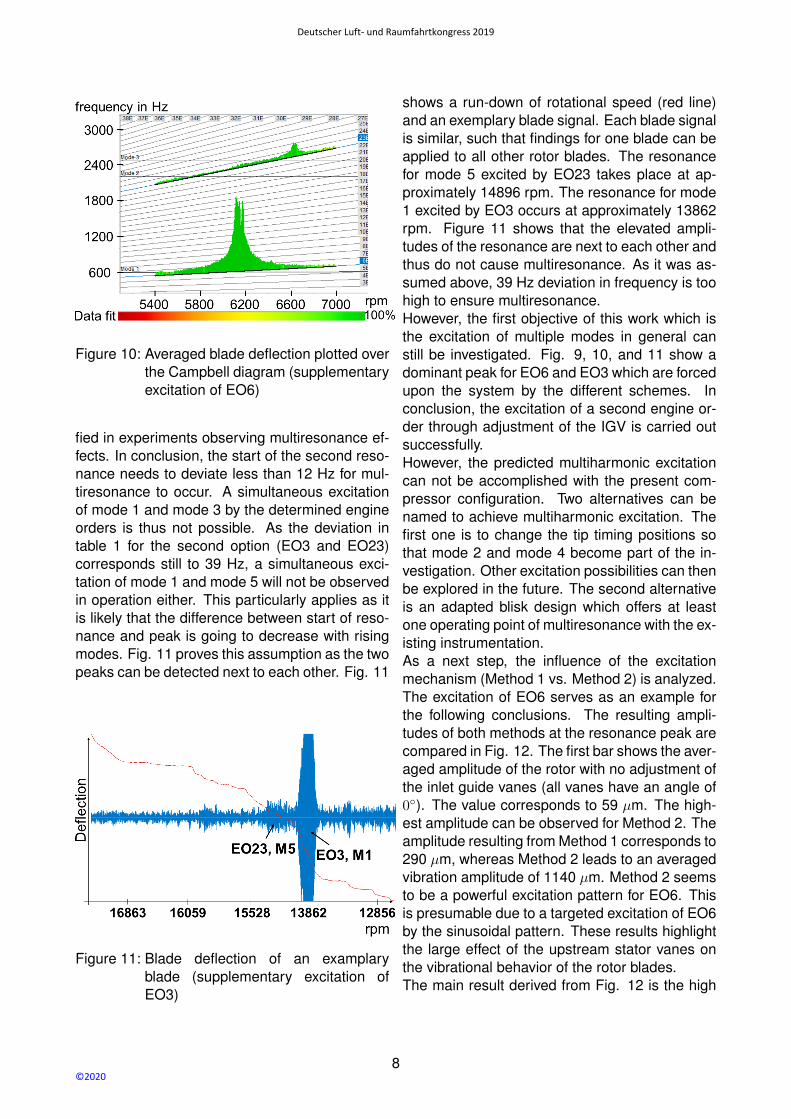
Figure 10: Averaged blade deflection plotted overthe Campbell diagram (supplementaryexcitation of EO6)
fied in experiments observing multiresonance ef-fects. In conclusion, the start of the second reso-nance needs to deviate less than 12 Hz for mul-tiresonance to occur. A simultaneous excitationof mode 1 and mode 3 by the determined engineorders is thus not possible. As the deviation intable 1 for the second option (EO3 and EO23)corresponds still to 39 Hz, a simultaneous exci-tation of mode 1 and mode 5 will not be observedin operation either. This particularly applies as itis likely that the difference between start of reso-nance and peak is going to decrease with risingmodes. Fig. 11 proves this assumption as the twopeaks can be detected next to each other. Fig. 11
Figure 11: Blade deflection of an examplaryblade (supplementary excitation ofEO3)
shows a run-down of rotational speed (red line)and an exemplary blade signal. Each blade signalis similar, such that findings for one blade can beapplied to all other rotor blades. The resonancefor mode 5 excited by EO23 takes place at ap-proximately 14896 rpm. The resonance for mode1 excited by EO3 occurs at approximately 13862rpm. Figure 11 shows that the elevated ampli-tudes of the resonance are next to each other andthus do not cause multiresonance. As it was as-sumed above, 39 Hz deviation in frequency is toohigh to ensure multiresonance.However, the first objective of this work which isthe excitation of multiple modes in general canstill be investigated. Fig. 9, 10, and 11 show adominant peak for EO6 and EO3 which are forcedupon the system by the different schemes. Inconclusion, the excitation of a second engine or-der through adjustment of the IGV is carried outsuccessfully.However, the predicted multiharmonic excitationcan not be accomplished with the present com-pressor configuration. Two alternatives can benamed to achieve multiharmonic excitation. Thefirst one is to change the tip timing positions sothat mode 2 and mode 4 become part of the in-vestigation. Other excitation possibilities can thenbe explored in the future. The second alternativeis an adapted blisk design which offers at leastone operating point of multiresonance with the ex-isting instrumentation.As a next step, the influence of the excitationmechanism (Method 1 vs. Method 2) is analyzed.The excitation of EO6 serves as an example forthe following conclusions. The resulting ampli-tudes of both methods at the resonance peak arecompared in Fig. 12. The first bar shows the aver-aged amplitude of the rotor with no adjustment ofthe inlet guide vanes (all vanes have an angle of0◦). The value corresponds to 59 µm. The high-est amplitude can be observed for Method 2. Theamplitude resulting from Method 1 corresponds to290 µm, whereas Method 2 leads to an averagedvibration amplitude of 1140 µm. Method 2 seemsto be a powerful excitation pattern for EO6. Thisis presumable due to a targeted excitation of EO6by the sinusoidal pattern. These results highlightthe large effect of the upstream stator vanes onthe vibrational behavior of the rotor blades.The main result derived from Fig. 12 is the high
8
Deutscher Luft- und Raumfahrtkongress 2019
©2020
Figure 12: Averaged blade deflection of mode 1
increase of amplitude for Method 2. The ampli-tude for the sinusoidal excitation pattern is nearly4 times higher than the amplitudes resulting fromthe excitation through Method 1. The amplituderesulting from Method 1 in turn is nearly 5 timeshigher than the amplitude without any defined ex-citation.
4. CONCLUSIONS AND OUTLOOK
Multiharmonic effects are investigated experi-mentally specifically for multiresonance in a highspeed axial compressor equipped with a singlestage blisk and adjustable vanes upstream anddownstream of the rotor. The numerically pre-dicted multiresonance could not be achieved inoperation. A separation of 15 Hz for mode 1and 12 Hz for mode 3, respectively appears tobe the maximum separation by which two reso-nance peaks can lie apart from each other, basedupon the shape of the fading curve. However, theexcitation mechanism itself could be verified asincrease in amplitude could be observed for bothmethods explored.The gathered experimental data will be used infuture work to improve the numerical model whichwas used to predict multiresonance and serve asboundary conditions for numerical aerodynamicand aeroelastic simulations. Further investiga-tions move the tip timing measurement positionsto the blade leading edge in such a way that mode2 and 4 can also be explored for possible mul-tiresonance.
ACKNOWLEDGEMENTS
The results are gained within the research projectC6 “Aeroelasticity of Multistage Axial Compres-sors“ funded by the Deutsche Forschungsge-meinschaft (DFG, German Research Foundation)– SFB 871/3 – 119193472. The authors kindlythank DFG for the financial support to accomplishthis research project.
9
Deutscher Luft- und Raumfahrtkongress 2019
©2020
References
[1] Fanny M Besem, Robert E Kielb, Paul Galpin, Laith Zori, and Nicole L Key. Mistuned forced re-sponse predictions of an embedded rotor in a multistage compressor. Journal of Turbomachinery,138(6), 2016.
[2] R Bladh, MP Castanier, and Christophe Pierre. Effects of multistage coupling and disk flexibilityon mistuned bladed disk dynamics. J. Eng. Gas Turbines Power, 125(1):121–130, 2003.
[3] VR Capece, SR Manwaring, and S Fleeter. Unsteady blade row interactions in a multistagecompressor. Journal of Propulsion and Power, 2(2):168–174, 1986.
[4] D Heller, IA Sever, and CW Schwingshackl. A method for multi-harmonic vibration analysis ofturbomachinery blades using blade tip-timing and clearance sensor waveforms and optimizationtechniques. Mechanical Systems and Signal Processing, 142:106741, 2020.
[5] Christian Keller, Andreas Kellersmann, Jens Friedrichs, and Joerg R Seume. Influence of geo-metric imperfections on aerodynamic and aeroelastic behavior of a compressor blisk. In ASMETurbo Expo 2017: Turbomachinery Technical Conference and Exposition. American Society ofMechanical Engineers Digital Collection, 2017.
[6] Olaf Lemke. Aktive minderung des drehklangs einer axialen fanstufe mittels drucklufteinblasungin den blattspitzenbereich. 2014.
[7] Jing Li, Nyansafo Aye-Addo, Nicholas Kormanik III, Douglas Matthews, Nicole Key, and RobertKielb. Mistuned higher-order mode forced response of an embedded compressor rotor: Partiasteady and unsteady aerodynamics. In Turbo Expo: Power for Land, Sea, and Air, volume50930, page V07BT36A021. American Society of Mechanical Engineers, 2017.
[8] William L Murray III and Nicole L Key. Experimental investigation of a forced-response conditionin a multistage compressor. Journal of Propulsion and Power, 31(5):1320–1329, 2015.
10
Deutscher Luft- und Raumfahrtkongress 2019
©2020