Investigation of Implantable Medical Device EMI Due to Radio Waves from RFID reader/writers
39
Document No JAISA-CRF0700101 Investigation of Implantable Medical Device EMI Due to Radio Waves from RFID reader/writers Japan Automatic Identification Systems Association, Japan Wireless Technology & EMC Research Lab. Graduate School of Information Science and Technology, Hokkaido University, Japan. This document is update of: WG4 SG5 March 2006 Kyoto meeting WG4 SG5 July 2006 Vancouver meeting WG4 SG3 August 2006 Paris meeting
Transcript of Investigation of Implantable Medical Device EMI Due to Radio Waves from RFID reader/writers

Document No JAISA-CRF0700101
Investigation of Implantable Medical Device EMI Due to Radio Waves from
RFID reader/writers
Japan Automatic Identification Systems Association, Japan
Wireless Technology & EMC Research Lab.Graduate School of Information Science and Technology,
Hokkaido University, Japan.
This document is update of:WG4 SG5 March 2006 Kyoto meetingWG4 SG5 July 2006 Vancouver meetingWG4 SG3 August 2006 Paris meeting

Wireless Technologies & EMC Research Lab. Document No JAISA-CRF0700101
Contents
Objectives
Electromagnetic interference (EMI) experiments
Measurement system for electromagnetic field (EMF) distribution
Examples of numerical analysis of electric fields of antennas
Conclusions and future works

Wireless Technologies & EMC Research Lab. Document No JAISA-CRF0700101
ObjectivesPrecise EMI assessment on implantable medical devices
Develop EMI estimation method: computer simulation
Contribute to the study of countermeasures
EMI experiments
Measurement of EMF distributions Numerical analysis
Radio wave from RFID Field strength
Mechanisms
EMI characteristics due to RFID reader/writers onimplantable cardiac pacemakers / implantable cardioverter-defibrillators (ICD)
Validity
EstimationThreshold level

Wireless Technologies & EMC Research Lab. Document No JAISA-CRF0700101
EMI experiments
Number of implantable medical devices Number of RFID reader/writer antennas
73
ICDs
2720200613102005
TotalPacemakersFiscal year
Breakdown of EMI experiments
EMI with different operating modes and functions – pacing/sensing polarity, single/dual chamber mode, and antitachycardia functions are examined.
EMI tests of RFID reader/writers operated at the frequency bands –125 kHz, HF (13.56 MHz) , UHF (950 MHz) , and 2.45 GHz are carried out.
02
UHF
22
2.45 GHz
214
HF
27420061042005
Total125 kHz
Fiscal year

Wireless Technologies & EMC Research Lab. Document No JAISA-CRF0700101
Configuration of the experimental system
Oscilloscope
Chart recorderPacemaker / ICD
Human body model
Function generator(Cardiac pulse)
Antenna Controller
Interferencedistance
1.8 w/v %saline
Oscilloscope & Chart Recorder
Function Generator
RFID reader/writer
Cardiac pacemaker
34 cm
36 cmLead wire
Ventricular electrode Atrial electrode
Saline solution(NaCl 0.18 w/v %)
RFID reader/writer
antenna
Human body model
Interference distance

Wireless Technologies & EMC Research Lab. Document No JAISA-CRF0700101
Overview of the test system
Human torso phantom
Two-axis measurement platform
Chart recorder ECG signal generator/detector
Oscilloscope
RFID reader/writer antenna
x-axis direction
y-axis direction

Wireless Technologies & EMC Research Lab. Document No JAISA-CRF0700101
EMI test results: FY2005
Affected Rate: 14% (107 / 768 modes)
0-4 cm5-9 cm 10-14
cm 15-19cm 20 cm-
Maximum1.0 mV
2.4 mV5.6 mV
Minimum
0
20
40
60
80
100
Affe
cted
mod
es (C
umul
ativ
e gr
aph)
Maximum interference distance (cm) Sensitivity of pacemakers and ICDs
Maximum interference distance: 15 cm
Affected Rate: 3% (26 / 768 modes)Maximum interference distance: 11 cm
Maximum sensitivity
Minimum sensitivity
Maximum1.0 mV2.4 mV5.6 mVMinimum
The results of FY2006 and FY2005 show no significant differences. Statistical processing of EMI characteristics will be carried out.

Wireless Technologies & EMC Research Lab. Document No JAISA-CRF0700101
Measurement of EMF distributions
To determine threshold EMF level and mechanism causing EMI, boththe electric and magnetic field distributions of RFID reader/writer antennas are measured.
Obtained data is also used to check the validity of the numerical analysis results.
Purposes of EMF distribution measurements
The relationship between EMI occurrence probability and EMF distributions are investigated by using measured results.
EMI characteristics obtained by test experiments EMF distributions or strength
EMF strength obtained by numerical analysis EMI estimation

Wireless Technologies & EMC Research Lab. Document No JAISA-CRF0700101
Measurement system configurations Automatic EMF measurement system is developed.
RFID reader/writer antenna ControllerSpectrum analyzer or computer
Electric or magnetic field probe
RFID reader/writer antenna
Magnetic field probe
y-axis
z-axis
x-axis
Automatic field positioner
Spectrum analyzerComputer

Wireless Technologies & EMC Research Lab. Document No JAISA-CRF0700101
-100 -50 0 50 100
100
50
0
-50
-100
Example of measured EMF distributions
zy
x
RFID reader/writerantenna
Magnetic field
The relationship between EMI occurrence probability and EMF distributions are now under investigation.
-100 -50 0 50 1000
-50
-100
-150
-200
Magnetic field distributions of a handheld-type HF antenna
3D magnetic field distributions(Measurement interval: 1cm)
xy-plane (z = 0 cm) xz-plane (y = 0 cm)
2D magnetic field distributions(Measurement interval: 1cm)
Unit: mmUnit: mm

Wireless Technologies & EMC Research Lab. Document No JAISA-CRF0700101
Numerical analysisBreakdown of numerical analysis
To develop a numerical EMI estimation methodology, we have constructed analysis model and conducted fundamental numerical analyses.
Antennas operating in the UHF and 2.45 GHz are suitable for employed numerical analysis method (FDTD method), however, 125 kHz and HF requires further investigation.

Wireless Technologies & EMC Research Lab. Document No JAISA-CRF0700101
Examples of analysis results
Analytical model
The human body model and UHF standard dipole antenna
A 2.45GHz RFID reader/writer antenna
Calculated electric fields(perpendicular to the antenna feed point)
Analytical model Calculated electric fields(surface of the phantom)
Current distributions on the antenna

Wireless Technologies & EMC Research Lab. Document No JAISA-CRF0700101
Conclusions and future worksConclusions
Future works
Detailed experiments to assess the EMI due to RFID reader/writers on implantable medical devices were conducted.
EMF distributions were measured precisely.
Statistical processing of EMI test results of FY2005 and FY2006.
Investigate electromagnetic conditions such as waveform and intermittent period to reduce EMI on implantable medical devices.
Investigate applicability of super computer to develop numerical EMI estimation method.
Fundamental investigations of a numerical analyses methodology were carried out.

Wireless Technologies & EMC Research Lab. Document No JAISA-CRF0700101
Notification of RFID
Gate Type RFID Others RFID For controlled areas RFID
JAISA will provide the design of above signs to NB of ISO/IEC JTC1/SC31, P-Members and O-Members.You can change the trade mark.

Wireless Technologies & EMC Research Lab. Document No JAISA-CRF0700101
Wireless Technologies & EMC Research Lab. Document No JAISA-CRF0700101
Results of 125 kHz RFID reader/writers
0-4 cm 5-9 cm 10-14cm 15-19
cm 20 cm-
Maximum1.0 mV
2.4 mV5.6 mV
Minimum
0
20
40
60
80
100
Affe
cted
mod
es (C
umul
ativ
e gr
aph)
Maximum interference distance (cm)
Maximum1.0 mV2.4 mV5.6 mVMinimum
Maximum interference distance of EMI: 15 cm
Number of antennas: 4
Specifications: ISO/IEC 18000-2
Total test modes: 320 modes
Affected modes: 103 modesAffected rate: 32 %
Communication distance: 0 - 28 cm
Conditions for 125 kHz RFID reader/writers
Results
About 30 % of test mode results due to magnetic field from antennas.
Sensitivity of pacemakers and ICDs

Wireless Technologies & EMC Research Lab. Document No JAISA-CRF0700101
Results of HF RFID reader/writers
0-4 cm 5-9 cm 10-14cm 15-19
cm 20 cm-
Maximum1.0 mV
2.4 mV5.6 mV
Minimum
0
20
40
60
80
100
Affe
cted
mod
es (C
umul
ativ
e gr
aph)
Maximum interference distance (cm)
Sensitivity of pacemakers and ICDs
Maximum interference distance of EMI: 5 cm
Number of antennas: 2
Specifications: ISO/IEC 18000-3
Total test modes: 160 modes
Affected modes: 4 modesAffected rate: 3 %
Communication distance: 0 - 50 cm
Conditions for HF RFID reader/writers
Results
EMI is reduced with magnetic field strength lower than the 125 kHz.
Input power (maximum): 4 W
Maximum1.0 mV2.4 mV5.6 mVMinimum

Wireless Technologies & EMC Research Lab. Document No JAISA-CRF0700101
Results of UHF RFID reader/writers
Number of antennas: 2
Specifications: EPC Class 1 Generation 2
Total test modes: 128 modes
Affected modes: 0 modeAffected rate: 0 %
Communication distance: 0 - 300 cm
Conditions for UHF RFID reader/writers
Results
EMI not detected during the experiments although UHF RFID reader/writers provide greater communication distance than
those using lower frequency bands.
Input power (maximum): 1 W
Wireless Technologies & EMC Research Lab. Document No JAISA-CRF0700101
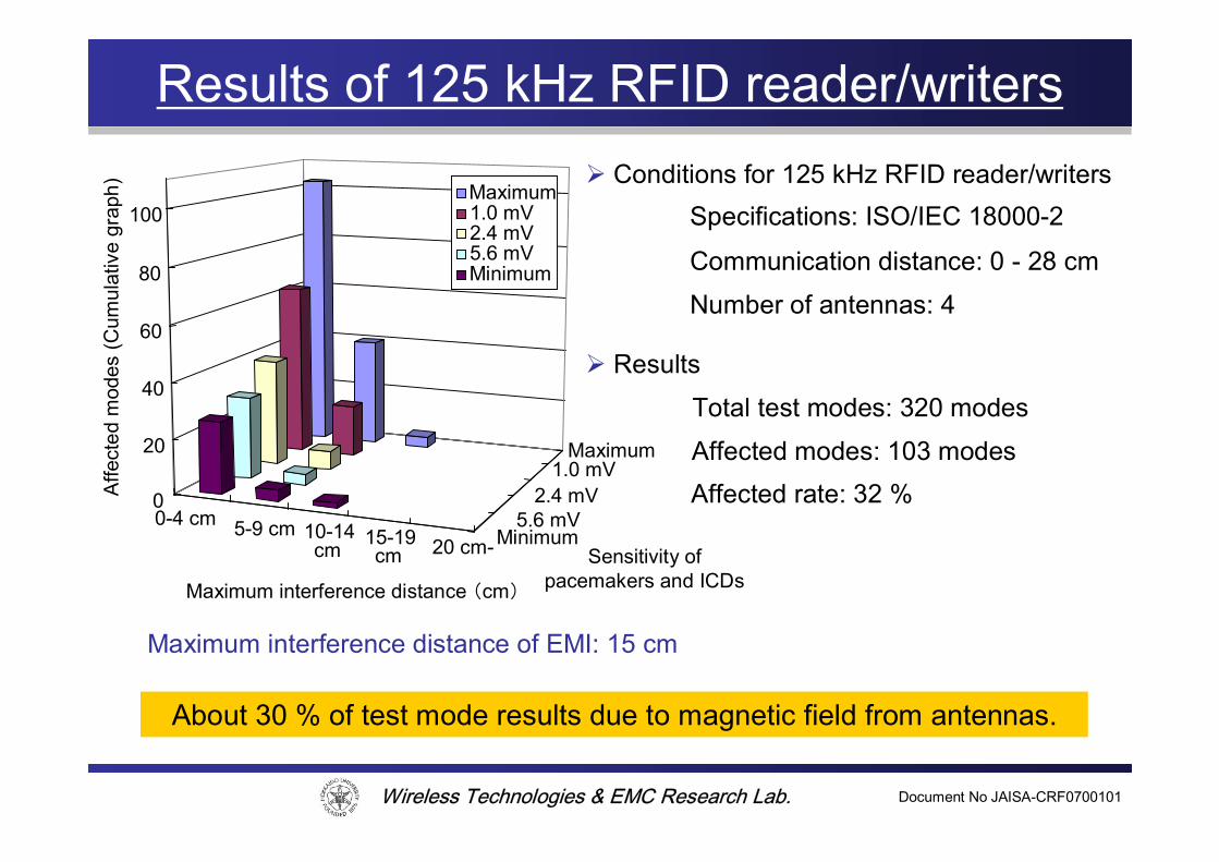
Results of 2.45 GHz RFID reader/writers
Number of antennas: 2
Specifications: ARIB STD-T81 / RCR STD-1
Total test modes: 160 modes
Affected modes: 0 modeAffected rate: 0 %
Communication distance: 0 - 30 cm
Conditions for 2.45 GHz RFID reader/writers
Results
No EMI detected for RFID reader/writer using the UHF and 2.45 GHz. Small input powers generate relatively low field strengths even in the
near field region of the antenna.
Input power (maximum): 300 mW

Wireless Technologies & EMC Research Lab. Document No JAISA-CRF0700101
Summary of all frequency
Affected Rate:3 % (26 / 768 modes)Maximum interference distance: 11 cm
Maximum sensitivity
Minimum sensitivity0-4 cm 5-9 cm 10-14
cm 15-19cm 20 cm-
Maximum1.0 mV
2.4 mV5.6 mV
Minimum
0
20
40
60
80
100
Affe
cted
mod
es (C
umul
ativ
e gr
aph)
Maximum interference distance (cm)
Maximum interference distance: 15 cm
Number of antennas: 10
Total test modes: 768 modes
Affected rate: 14 % (107 / 768 modes)
Conditions of EMI experiments
Results
As radio waves from lower frequency band RFID reader/writers have time-varying envelope curves or varying magnetic fields due to antenna motion,
the probability of EMI occurrence is high.
Sensitivity of pacemakers and ICDs
Maximum1.0 mV2.4 mV5.6 mVMinimum
Wireless Technologies & EMC Research Lab. Document No JAISA-CRF0700101

Wireless Technologies & EMC Research Lab. Document No JAISA-CRF0700101
Configuration of experimental test system
Controller orComputer
Distance: x
RFID reader/writerantenna
Saline solution(0.18 w/v %)
Torso phantom
Pacemaker or ICD
Lead wireElectrode
Chart recorderNEC San-ei RT3608
> 2 kΩECG signal generatorFunction generator
OscilloscopeYOKOGAWA DL9240L
The test system is based upon proposed one for estimation of EMI due to mobile phones.
We referred AAMI Standard PC69 and EMI test experiments reported by the Ministry of Internal Affairs and Communications of Japan.
Maximum interference distances are measured in centimeters.

Wireless Technologies & EMC Research Lab. Document No JAISA-CRF0700101
Maximum interference distance
Human body
RFID reader/writerantenna
Maximum interference distance
Maximum interference distance refers to the distance which causes EMI to disappear.
The human body is assumed to face an RFID reader/writer antenna.

Wireless Technologies & EMC Research Lab. Document No JAISA-CRF0700101
The human torso phantom
Cardiac pacemaker
34 cm
36 cmLead wire
Ventricular electrode Atrial electrode
Saline solution(NaCl 0.18 w/v %)
The human torso phantom is based upon Irnich’s flat torso phantom model.
Both atrial and ventricular electrodes enable us to separate each chambers’signal by more than 20 dB.
This phantom allows us to examine EMI with low interference by another chambers’ signal.
This construction of a human torso phantom is confirmed to give more conservative results for EMI estimations.

Wireless Technologies & EMC Research Lab. Document No JAISA-CRF0700101
PM/ICD operating mode and EMI test mode
EMI test mode
Pacemakers and ICDs operating mode VVI mode - the Ventricle chamber is paced, the Ventricle chamber is sensed,
and the response to sensing is Inhibited. AAI mode - the Atrium chamber is paced, the Atrium chamber is sensed,
and the response to sensing is Inhibited.
Sensing/pacing polarity
Unipolar mode – a metal housing of pacemakers and a tip electrode of lead wire.
Bipolar mode – a tip electrode and ring electrode located at the end of coaxial lead wire.
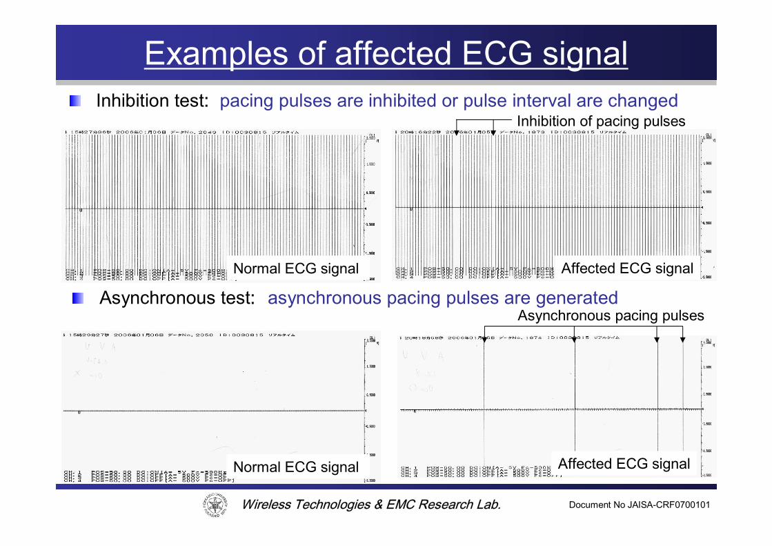
Inhibition test – Test mode with no ECG signal is injected. Pacing pulse is inhibited due to intermittent sensing of external noise or radio waves.
Asynchronous test – Test mode with ECG signal is injected. Pacing pulse is generated by noise reversion function of pacemakers triggered by the noise.

Wireless Technologies & EMC Research Lab. Document No JAISA-CRF0700101
Procedure of the test experimentsStart
(4) Recode ECG signal and measurement of maximum interference distance
End
(2) 125 kHz or HF (13.56 MHz)RFID reader/writer
(3) Exposure test (Inhibition / Asynchronous)With varying antenna position
(1) Set PM / ICD parameters.Sensitivity: maximum, Refractory: minimum
Operating mode: VVI or AAI, Polarity: Unipolar / Bipolar
(2) UHF (950 MHz) or 2.45 GHzRFID reader/writer
(3) Exposure test (Inhibition / Asynchronous)With fixed antenna position
Step down sensitivityYes
NoChange operating mode and polarity
EMI occurs?
Complete test with respect to all conditions
Wireless Technologies & EMC Research Lab. Document No JAISA-CRF0700101
Examples of affected ECG signal
Normal ECG signal Affected ECG signal
Inhibition of pacing pulses
Asynchronous pacing pulses
Inhibition test: pacing pulses are inhibited or pulse interval are changed
Asynchronous test: asynchronous pacing pulses are generated
Normal ECG signal Affected ECG signal

Wireless Technologies & EMC Research Lab. Document No JAISA-CRF0700101

Wireless Technologies & EMC Research Lab. Document No JAISA-CRF0700101
EMI occurrence mechanism
• Low frequency bands– Direct conducted current– Alternating magnetic field
• Electromotive force by following Faraday’s low
– High voltage electric field
• High frequency bands– Nonlinear characteristics of pacemaker’s input circuit– Envelop curve of signal are detected by the circuit

Wireless Technologies & EMC Research Lab. Document No JAISA-CRF0700101
EMI test mode for pacemakers
• Inhibition– Test mode with no injected ECG signal.– As the strength of the EMI increases, the effects is
usually inhibition due to intermittent sensing of the EMI by the pacemaker.
• Asynchronous– Test mode with injected ECG signal.– At the high strength, noise may be sensed
continuously, which can trigger a noise reversion mode, which is generally asynchronous pacing.

Wireless Technologies & EMC Research Lab. Document No JAISA-CRF0700101
EMI test mode for ICDs
• False positive mode– Test mode with no injected ECG signal– Defibrillation functions are triggered by the EMI.
• False negative mode – Test mode with injected ECG signal which is same as
defibrillation ECG– Defibrillation functions are disabled by the EMI.

Wireless Technologies & EMC Research Lab. Document No JAISA-CRF0700101
PM/ICD sensing/pacing polarity
• Pacemaker's two electrode– A different electrode and an indifferent electrode
• Sensing/pacing signal is carried by– Unipolar: “a metal housing of pacemakers” and “a tip
electrode of lead wire”
– Bipolar: “a tip electrode and ring electrode with located at the end of coaxial lead wire”

Wireless Technologies & EMC Research Lab. Document No JAISA-CRF0700101

Wireless Technologies & EMC Research Lab. Document No JAISA-CRF0700101
Block diagram of a pacemaker sense amplifier
“Block diagram of a pacemaker sense amplifier showing the main functional elements of a typical atrial or ventricular sense amplifier.”
K. A. Ellenbogen, G. N. Kay, C, -P, Lau, and B. L. Wilkoff, Clinical Cardiac Pacing, Defibrillation, and Resynchronization Therapy, 3RD EDITION. Pennsylvania: Saunders, 2007.
Figure 7-3

Wireless Technologies & EMC Research Lab. Document No JAISA-CRF0700101
Sense amplifier sensitivity
“Sense amplifier sensitivity versus frequency plots. Signals above the threshold (or sensitivity) line are sensed as P waves or R waves. Signals below the sensitivity line are not sensed. Frequencies of typical signals are superimposed on the plot.”K. A. Ellenbogen, G. N. Kay, C, -P, Lau, and B. L. Wilkoff, Clinical Cardiac Pacing, Defibrillation, and Resynchronization Therapy, 3RD EDITION. Pennsylvania: Saunders, 2007.
Figure 7-6

Wireless Technologies & EMC Research Lab. Document No JAISA-CRF0700101
Filtered ventricular EGM
K. A. Ellenbogen, G. N. Kay, C, -P, Lau, and B. L. Wilkoff, Clinical Cardiac Pacing, Defibrillation, and Resynchronization Therapy, 3RD EDITION. Pennsylvania: Saunders, 2007.
“A. Unfiltered ventricular EGM. Note the prominent T wave. B. The same EGM after filtering by a pacemaker sense amplifier. Filtering has greatly reduced the amplitude of the T wave.”
Figure 7-4

Wireless Technologies & EMC Research Lab. Document No JAISA-CRF0700101
Spectrum of filtered EGM
“Fast Fourier Transform (FFT) showing frequency content of unfiltered and filtered ventricular EGMs. Top, spectrum of an unfiltered EGM. Note the frequency content in the 2 to 10 Hz range, caused by T waves; also note the frequency content between 1-and 40 Hz, caused by R waves. Bottom, Spectrum of filtered EGM. The frequency content from 2 to 10 Hz is removed by filtering.”
K. A. Ellenbogen, G. N. Kay, C, -P, Lau, and B. L. Wilkoff, Clinical Cardiac Pacing, Defibrillation, and Resynchronization Therapy, 3RD EDITION. Pennsylvania: Saunders, 2007.
Figure 7-5
Wireless Technologies & EMC Research Lab. Document No JAISA-CRF0700101
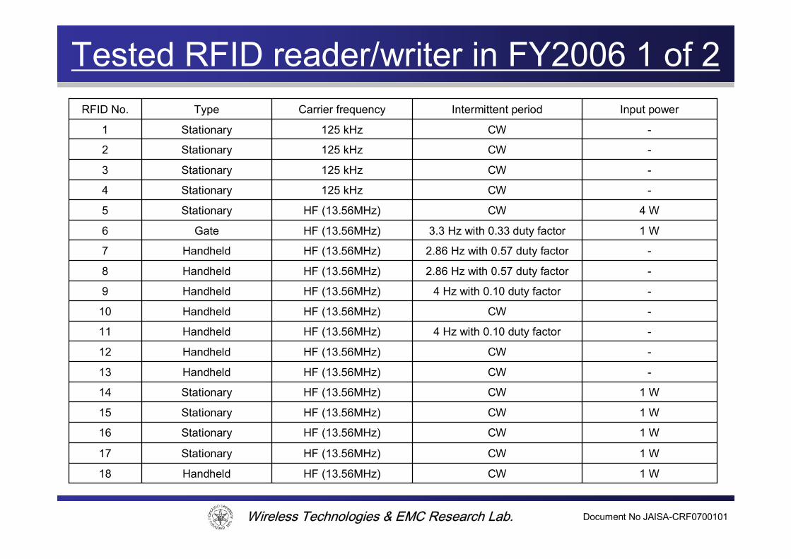
Tested RFID reader/writer in FY2006 1 of 2
1 WCWHF (13.56MHz)Handheld18
1 WCWHF (13.56MHz)Stationary17
1 WCWHF (13.56MHz)Stationary16
-CW125 kHzStationary2
1 WCWHF (13.56MHz)Stationary15
-CWHF (13.56MHz)Handheld13
1 WCWHF (13.56MHz)Stationary14
-4 Hz with 0.10 duty factorHF (13.56MHz)Handheld9
-4 Hz with 0.10 duty factorHF (13.56MHz)Handheld11
Handheld
Handheld
Handheld
Handheld
Gate
Stationary
Stationary
Stationary
Stationary
Type
HF (13.56MHz)
HF (13.56MHz)
HF (13.56MHz)
HF (13.56MHz)
HF (13.56MHz)
HF (13.56MHz)
125 kHz
125 kHz
125 kHz
Carrier frequency
-
-
-
-
1 W
4 W
-
-
-
Input power
CW12
2.86 Hz with 0.57 duty factor8
CW3
CW1
3.3 Hz with 0.33 duty factor6
CW5
CW10
CW4
2.86 Hz with 0.57 duty factor7
Intermittent periodRFID No.

Wireless Technologies & EMC Research Lab. Document No JAISA-CRF0700101
Tested RFID reader/writer in FY2006 2 of 2
200 mW-2.45 GHzStationary27
300 mWCWHF (13.56MHz)Stationary20
Stationary
Gate
Handheld
Stationary
Stationary
Stationary
Stationary
Type
2.45 GHz
HF (13.56MHz)
HF (13.56MHz)
HF (13.56MHz)
HF (13.56MHz)
HF (13.56MHz)
HF (13.56MHz)
Carrier frequency
300 mW
4 W
-
300 mW
300 mW
300 mW
300 mW
Input power
-26
CW21
CW19
CW24
CW23
CW22
50 Hz with 0.50 duty factor25
Intermittent periodRFID No.