
A Wireless Implantable Sensor Design With Subcutaneous ... · the feasibility of a wireless...
8
SPECIAL SECTION ON WEARABLE AND IMPLANTABLE DEVICES AND SYSTEMS Received May 23, 2018, accepted June 23, 2018, date of publication July 3, 2018, date of current version July 19, 2018. Digital Object Identifier 10.1109/ACCESS.2018.2851940 A Wireless Implantable Sensor Design With Subcutaneous Energy Harvesting for Long-Term IoT Healthcare Applications TAIYANG WU , (Student Member, IEEE), JEAN-MICHEL REDOUTÉ , (Senior Member, IEEE), AND MEHMET RASIT YUCE , (Senior Member, IEEE) Department of Electrical and Computer Systems Engineering, Monash University, Melbourne, VIC 3800, Australia Corresponding author: Mehmet Rasit Yuce ([email protected]) This work was supported by the Australian Research Council Future Fellowships under Grant FT130100430. ABSTRACT In this paper, a wireless implantable sensor prototype with subcutaneous solar energy harvest- ing is proposed. To evaluate the performance of a flexible solar panel under skin, ex-vivo experiments are conducted under natural sunlight and artificial light sources. The results show that the solar panel covered by a 3 mm thick porcine flap can output tens of microWatts to a few milliWatts depending on the light conditions. The subcutaneous solar energy harvester is tested on different body parts, which suggests the optimal position for the harvester to implant is between neck and shoulder. A wireless implantable system powered by the subcutaneous energy harvester is presented, which consists of a power management circuit, a temperature sensor, and a Bluetooth low energy module. An application is developed for data visualization on mobile devices, which can be a gateway for future IoT-based healthcare applications. The entire device is embedded in a transparent silicone housing (38 mm × 32 mm × 4 mm), including a 7 mAh rechargeable battery for energy storage. The average power consumption of the implants is about 30 μW in a 10 min operation cycle. With the subcutaneous solar energy harvester, the self-powered operation of the implantable sensor prototype is demonstrated by long-term experimental results. Two worst-case scenarios (no exposure to light and battery depletion) are considered with ex-vivo experiment simulations. INDEX TERMS Implantable biomedical device, energy harvesting, wireless communication, self-powered system, long-term healthcare. I. INTRODUCTION With the increase of average human lifespan, chronic diseases are one of the predominant challenges to people’s health globally [1]. Many chronic diseases, such as cardiovascular, neurological, and glucose disorders, can be treated or mon- itored by implanted biomedical devices [2]–[5]. One of the limitations in the development of implantable electronic devices is the power supply, as most of the implants use batteries with finite lifetime [6]. Periodical surgeries for bat- tery replacement will increase patients’ physical, psycholog- ical, and financial burdens. With the emerging of Internet of Things (IoT) in healthcare monitoring, a continuous power source is necessary to maintain long-term connectivity [7]. Energy harvesting technique is a promising solution to the powering issue of implantable electronics. Researchers worldwide have proposed several implantable energy harvesting methods using different sources, such as thermal energy, mechanical motion, and radio frequency (RF) energy transfer [6], [8], [9]. In [10], Kim et al. propose a flexible piezoelectric energy harvester, which generates elec- tricity from the contraction and relaxation of a porcine heart. In [11], Zheng et al. attempt to collect biomechanical energy from a biodegradable triboelectric nanogenerator. However, it is constrained by its susceptibility to humidity and fric- tion. Apart from the aforementioned energy sources, another approach is to convert light that penetrates through human skin into electricity with a photovoltaic (PV) panel. Though human skin and subcutaneous tissues will block some light, there is a transparency window in the near-infrared (NIR) spectrum region where light passes the skin [12]. The work in [13] studies the properties of different silicon and GaAs PV cells within the NIR region, where a 850 nm microscope- compatible LED is used as the light source. Light in the NIR spectrum region is only a portion of the ambient light, VOLUME 6, 2018 2169-3536 2018 IEEE. Translations and content mining are permitted for academic research only. Personal use is also permitted, but republication/redistribution requires IEEE permission. See http://www.ieee.org/publications_standards/publications/rights/index.html for more information. 35801
Transcript of A Wireless Implantable Sensor Design With Subcutaneous ... · the feasibility of a wireless...

SPECIAL SECTION ON WEARABLE AND IMPLANTABLE DEVICES AND SYSTEMS
Received May 23, 2018, accepted June 23, 2018, date of publication July 3, 2018, date of current version July 19, 2018.
Digital Object Identifier 10.1109/ACCESS.2018.2851940
A Wireless Implantable Sensor Design WithSubcutaneous Energy Harvesting forLong-Term IoT Healthcare ApplicationsTAIYANG WU , (Student Member, IEEE), JEAN-MICHEL REDOUTÉ , (Senior Member, IEEE),AND MEHMET RASIT YUCE , (Senior Member, IEEE)Department of Electrical and Computer Systems Engineering, Monash University, Melbourne, VIC 3800, Australia
Corresponding author: Mehmet Rasit Yuce ([email protected])
This work was supported by the Australian Research Council Future Fellowships under Grant FT130100430.
ABSTRACT In this paper, a wireless implantable sensor prototype with subcutaneous solar energy harvest-ing is proposed. To evaluate the performance of a flexible solar panel under skin, ex-vivo experiments areconducted under natural sunlight and artificial light sources. The results show that the solar panel coveredby a 3 mm thick porcine flap can output tens of microWatts to a few milliWatts depending on the lightconditions. The subcutaneous solar energy harvester is tested on different body parts, which suggests theoptimal position for the harvester to implant is between neck and shoulder. A wireless implantable systempowered by the subcutaneous energy harvester is presented, which consists of a power management circuit,a temperature sensor, and a Bluetooth low energy module. An application is developed for data visualizationon mobile devices, which can be a gateway for future IoT-based healthcare applications. The entire deviceis embedded in a transparent silicone housing (38 mm × 32 mm × 4 mm), including a 7 mAh rechargeablebattery for energy storage. The average power consumption of the implants is about 30 µW in a 10 minoperation cycle. With the subcutaneous solar energy harvester, the self-powered operation of the implantablesensor prototype is demonstrated by long-term experimental results. Two worst-case scenarios (no exposureto light and battery depletion) are considered with ex-vivo experiment simulations.
INDEX TERMS Implantable biomedical device, energy harvesting, wireless communication, self-poweredsystem, long-term healthcare.
I. INTRODUCTIONWith the increase of average human lifespan, chronic diseasesare one of the predominant challenges to people’s healthglobally [1]. Many chronic diseases, such as cardiovascular,neurological, and glucose disorders, can be treated or mon-itored by implanted biomedical devices [2]–[5]. One of thelimitations in the development of implantable electronicdevices is the power supply, as most of the implants usebatteries with finite lifetime [6]. Periodical surgeries for bat-tery replacement will increase patients’ physical, psycholog-ical, and financial burdens. With the emerging of Internet ofThings (IoT) in healthcare monitoring, a continuous powersource is necessary to maintain long-term connectivity [7].Energy harvesting technique is a promising solution to thepowering issue of implantable electronics.
Researchers worldwide have proposed several implantableenergy harvesting methods using different sources, such as
thermal energy, mechanical motion, and radio frequency (RF)energy transfer [6], [8], [9]. In [10], Kim et al. propose aflexible piezoelectric energy harvester, which generates elec-tricity from the contraction and relaxation of a porcine heart.In [11], Zheng et al. attempt to collect biomechanical energyfrom a biodegradable triboelectric nanogenerator. However,it is constrained by its susceptibility to humidity and fric-tion. Apart from the aforementioned energy sources, anotherapproach is to convert light that penetrates through humanskin into electricity with a photovoltaic (PV) panel. Thoughhuman skin and subcutaneous tissues will block some light,there is a transparency window in the near-infrared (NIR)spectrum region where light passes the skin [12]. The workin [13] studies the properties of different silicon and GaAsPV cells within the NIR region, where a 850 nm microscope-compatible LED is used as the light source. Light in theNIR spectrum region is only a portion of the ambient light,
VOLUME 6, 20182169-3536 2018 IEEE. Translations and content mining are permitted for academic research only.
Personal use is also permitted, but republication/redistribution requires IEEE permission.See http://www.ieee.org/publications_standards/publications/rights/index.html for more information.
35801

T. Wu et al.: Wireless Implantable Sensor Design With Subcutaneous Energy Harvesting
thus S. Ayazian et al. attempt to use a 150 W halogenmicroscope illuminator to power a PV-driven implantablesensor [14]. A batteryless cardiac pacemakerwith 3monocrys-talline solar cells is presented in [15], which demonstratesthe real-life application by the in-vivo test in a pig. In [16],Bereuter et al. study the long-term operation of subcutaneoussolar energy harvesting using an optical filter to substitutehuman skin. The average power harvested is about 67 µWwith volunteers wearing the experimental device in their dailylife.
The development of implantable biomedical sensors alsorequires appropriate wireless communication for data trans-mission [17], [18], which further increases power consump-tion. The work in [10] uses a flexible piezoelectric energyharvester to power a wirelessUSB NL development kit, andsuccessfully switches on and off a light bulb placed 5 metersaway. In this paper, a complete implantable sensor prototypewith subcutaneous solar energy harvesting and wireless com-munication is proposed, as shown in Figure 1. The prototypeincorporates a temperature sensor and a Bluetooth low energy(BLE) module in a transparent silicon housing. With thepower from a flexible solar panel, it can measure the innerbody temperature and send data to a mobile device, which canbe a gateway for IoT-based healthcare monitoring. A long-term ex-vivo experiment (including two worst-case scenar-ios) of the implantable prototype is conducted to demonstratethe feasibility of a wireless implantable sensor design withsubcutaneous energy harvesting.
FIGURE 1. The proposed implantable sensor system prototype withsubcutaneous solar energy harvesting.
The remainder of the paper is organized as follows:Section II presents the electrical properties of a flexible solarpanel when covered by a 3 mm thick porcine skin flap underdifferent ambient light conditions. In Section III, we com-pare the performance of the subcutaneous solar energy har-vester on the different body parts (wrist, shoulder and neck).The implementation of the prototype’s electrical compo-nents is described in Section IV. Section V demonstrates the
experimental results of the prototype’s long-term ex-vivooperation and two worst-case scenarios. The conclusion andfuture improvement of the work are discussed in the lastsection.
II. ELECTRICAL PROPERTIES OF A FLEXIBLE SOLARPANEL UNDER SKINSolar energy harvesting has been adopted in many wear-able biomedical sensor applications as an alternative to abattery [7], [19], [20]. However, the performance of thesolar panel in an implantable sensor may be attenuatedby the light absorption and scattering due to the skin andsubcutaneous tissues. The research in [12] shows that skinhas an optical transparency window (650-950 nm) in theNIR spectrum regionwhere light can penetrate. E.Moon et al.propose a special PV cell with high efficiency in the NIRregion for subcutaneous infrared energy harvesting, whichuses a 850 nm LED as light source. In [14], a high-power(150 W) halogen microscope illuminator is utilized to poweran implantable PV-driven sensor. In an initial work [21],we have studied the characteristics of a flexible solar panelunder a porcine skin when illuminated by different ambi-ent light. The solar panel used in this experiment, SP-37,is an off-the-shelf product from PowerFilm R©. Several testsare conducted under different irradiance levels of sunlightand a 24 W bulb to evaluate its performance in real-lifesituations.
A. NATURAL SUNLIGHTThe electrical properties of the flexible solar panel underdirect sunlight when covered by a 3 mm thick (1 mm skinand 2 mm fat) porcine flap are shown in Figure 2. Differ-ent irradiance levels are considered under different weatherconditions, e.g. sunny day noon (1000 W/m2), partly cloudyday (450 W/m2), mostly cloudy day (150 W/m2), and mostly
FIGURE 2. The measured characteristics of the flexible solar panel undernatural sunlight: (a) I-V curve; (b) I-V curve (covered by porcine skin);(c) P-V curve; (d) P-V curve (covered by porcine skin).
35802 VOLUME 6, 2018

T. Wu et al.: Wireless Implantable Sensor Design With Subcutaneous Energy Harvesting
cloudy day late-afternoon (30 W/m2). The irradiance valuesare measured using a solar power meter, 1333R from TES R©.As shown in Figure 2(d), the maximum power from theflexible solar panel covered by the porcine flap is around5.5 mW under the best light situation (1000 W/m2) and90 µ under the worst light situation (30 W/m2). Accord-ing to the results in Figure 2 (c) and (d), the averagepower from the solar panel under the porcine flap isapproximately 5% to 10% of that when exposed to directsunlight.
B. ARTIFICIAL LIGHTFigure 3 illustrates the performance of the flexible solar panelwhen illuminated by normal artificial light, a 24 W cooldaylight fluorescent lamp bulb (1450 lm) from Philips R©
Tornado series. The lamp is placed at various distances tothe solar panel for different irradiance conditions, e.g. 8 cm(40 W/m2), 12cm (20 W/m2), 16cm (10 W/m2), and 22cm(4 W/m2). The results in Figure 3(d) show that the max-imum output power of the solar panel under the porcineflap varies from 100 µW to 1.4 mW at different distances.It is about 8% to 10% of that when directly illuminated bythe lamp, which corresponds to results from the sunlightconditions.
FIGURE 3. The measured characteristics of the flexible solar panel underartificial light: (a) I-V curve; (b) I-V curve (covered by porcine skin);(c) P-V curve; (d) P-V curve (covered by porcine skin).
In this section, the characteristics of a flexible solar panelcovered by a 3 mm thick porcine flap are presented. Theex-vivo experimental results show that the solar panel canoutput tens of microWatts to a few milliWatts when cov-ered under a porcine flap, depending on the light conditions.Although the power is about 5% to 10% of that when the solarpanel is exposed to direct light, it is sufficient to power ultralow-power electronic circuits. A wireless implantable sensorprototype powered by the proposed subcutaneous energy har-vester will be described in Section IV.
III. COMPARISON OF SOLAR ENERGY HARVESTING ONDIFFERENT BODY PARTSThe solar energy harvester may have varied performance ondifferent body parts due to the exposure to light. To findan optimal position for solar energy harvesting, the flexiblesolar panel (covered by a porcine flap) is placed on differentbody parts (wrist, shoulder and neck), as shown in Figure 4.However, the light exposed to the harvester may be influencedby lots of other elements (buildings, trees, subject move-ment, etc.). The following procedures are taken to ensure theresults are comparable:
• The experiments are conducted in an open area withoutother blocking.
• The experiments are conducted on a sunny day(no clouds) and a heavily cloudy day (no direct sunlight).
• The subject walks at a normal speed along a pre-definedtrack, as shown in Figure 5.
FIGURE 4. The flexible solar panel covered by a porcine flap is placed ondifferent body parts (wrist, shoulder and neck).
FIGURE 5. The subject walks along a pre-defined track in an open area.
The first experiment is taken on a sunny day noon(no clouds). The flexible solar panel covered by a 3 mm thickporcine flap is placed on a subject’s wrist (right), shoulder(right) and neck, respectively. The solar panel is used tocharge a 1 F supercapacitor through a power managementcircuit (will be discussed in Section IV). The subject walks
VOLUME 6, 2018 35803

T. Wu et al.: Wireless Implantable Sensor Design With Subcutaneous Energy Harvesting
at a normal speed along the track in Figure 5 for 2 cycles, andeach cycle takes about 10 minutes. During the experimentthe direct sunlight irradiance stays at a steady level, about950 to 1000 W/m2. The supercapacitor’s voltage charged bythe subcutaneous solar panel is illustrated in Figure 6. Whenthe subject walks from starting point A to turning point B,the supercapacitor on the neck is in a fast charge period asthe neck is exposed to the sunlight almost directly (with asmall angle). From point B to point C the neck is in anopposition direction to sunlight, thus the supercapacitor onthe neck is in a slow charge period. For the supercapacitoron the right wrist or right shoulder, it is charged slowly frompoint A to point C because of no direct exposure to sunlight.From point C to point A the neck supercapacitor is chargedfaster than from B to C but slower than from A to B, as theneck is exposed to sunlight with a large angle. The voltageof the supercapacitor on the right wrist or right shoulderincreases quickly from point C to point A due to the exposureto sunlight. Because the wrist is lower and swings more thanthe shoulder, the supercapacitor on the wrist is charged slowerthan that on the shoulder by the flexible solar panel under aporcine flap. For the second cycle in Figure 6, the voltagecurves of the supercapactor charged by the subcutaneoussolar panel on different body parts repeat a similar pattern,except the supercapacitor on the neck reaches an overchargeprotection voltage.
FIGURE 6. The voltage of a 1 F supercapacitor charged by a flexible solarpanel placed on different body parts on a sunny day.
Figure 7 shows the experimental results on a heavilycloudy day (the sun is totally blocked by cloud). Theirradiance level during the experiment varies from 100 to200W/m2 which is caused by cloud movement. In this exper-iment there is no distinctive fast or slow charge period of thesupercapacitor because there is no direct exposure to sunlight.However, the supercapacitor on the upper body (shoulder andneck) is charged faster than that on the wrist. The explanation
FIGURE 7. The voltage of a 1 F supercapacitor charged by a flexible solarpanel placed on different body parts on a heavily cloudy day.
is that wrist is less exposed to light due to the shadow of thebody and wrist movement. The results in Figure 6 and 7 showthat solar energy harvester on the neck outperforms those onthe other body parts. However, the power harvested may beaffected by many other shadows from the ambient in a real-life situation. Considering the body structure and clothing,the upper body area between the neck and shoulder may bean optimal position for subcutaneous solar energy harvesting.
IV. IMPLEMENTATION OF THE IMPLANTABLE SENSORPROTOTYPE WITH ENERGY HARVESTINGIn this section, an implantable sensor prototype poweredby the subcutaneous solar energy harvester is presented.The prototype consists of a power management circuit,a temperature sensor and a wireless communication module.Amobile application for sensor data visualization will also bedescribed. As the power from the subcutaneous solar panel isin the range of microWatts to a few milliWatts (maximum),the power consumption of the prototype needs to be ultra lowfor long-term operation.
A. POWER MANAGEMENT CIRCUITThe maximum power point tracking (MPPT) circuit is sig-nificant to solar energy harvesting, as the power from asolar panel varies a lot depending on the irradiance level andambient temperature [22]. In this work, a power manage-
ment IC, BQ25505 from Texas Instrument R©, is exploitedto maximize the power from the solar panel. BQ25505 hasan embedded MPPT algorithm based on the fraction opencircuit voltage (FOCV) method. The FOCV algorithm pro-poses the voltage of a solar panel at the maximum powerpoint is proportional to its open circuit voltage [23]. As shownin Figure 2(d) and 3(d), the maximum power point voltageof the flexible solar panel covered under a porcine flap is
35804 VOLUME 6, 2018

T. Wu et al.: Wireless Implantable Sensor Design With Subcutaneous Energy Harvesting
between 60% to 70% of its open circuit voltage. Thereforewe set a reference of 66.7% to BQ25505, which samples andupdates the maximum power point every 16 seconds.
B. TEMPERATURE SENSORTemperature is a vital signal of the human body, and animplantable temperature sensor has potential medical appli-cations such as inner body localized temperature monitoringand heating detection of other implants [24]. A high accuracy(0.1◦C from 37◦C to 39◦C) and low-power (600 µA at 2.7 Vto 3.3 V) temperature IC, the MAX30205 from Maxim R©,is implemented in this prototype. The MAX30205 is used inits one-shot mode, which sets the sensor to sleep (3.5 µA)most of the time and wakes it up periodically for a tempera-ture measurement (600 µA) in a few milli seconds.
C. WIRELESS COMMUNICATIONWireless transmission is a critical part in an implantablesensor system, which enables the communication betweeninner body and outside. However, its relatively high-powerconsumption raises new challenge to the power system of animplant. The proposed prototype incorporates a professionalgrade BLE module to transmit the implanted sensor data toa mobile device (a smartphone or tablet). The BLE module,RFD77101, has an on-chip antenna and a built-in microcon-troller (ARMCortexM0) for data processing before transmis-sion. The peak transmission current of RFD77101 is about8 mA, while its sleep current (with clock running) is lessthan 4 µA. In this work, a web-based application on theEvothings R© platform is developed to display sensor data ona mobile device.
All the electronic components are implemented on a smallflexible PCB (33mm× 27mm), as shown in Figure 8(a). Theflexible PCB is covered by the aforementioned solar panel,which is folded in half to reduce the size. The entire device isembedded into a transparent silicone rubber housing, which iscreated using Ecoflex 00-10 from Smooth-On R©. The curedrubber housing is soft, but strong and stretchy, as shownin Figure 8(b). Figure 8(c) describes the application for thedisplay of the implantable sensor data, which can be run on asmartphone or tablet with Bluetooth 4.0 technology.
D. POWER CONSUMPTIONAn implantable sensor needs to be ultra low-power for long-term operation without intervention. The proposed systemworks at 2.7 V, the minimum voltage of the temperaturesensor. Figure 9 demonstrates the current of the entire pro-totype at different operation mode. Although the peak trans-mission current of the BLE module is 8 mA, the averageworking current is between 400 to 500 µA for 5 seconds.This is because data is transmitted once when acknowledgedimmediately, or maximum three times when no acknowl-edgement received. The sleep current with clock running isaround 7 µA. By calculation, the average power of proposedimplantable sensor prototype is 130µW (average 48 µAat 2.7 V) for a 1 minute cycle (sleep for 55 seconds),
FIGURE 8. The proposed implantable sensor prototype: (a) A flexible PCBfor electronic components (33 mm × 27 mm); (b) The entire prototype ina stretchy transparent silicone housing (38 mm × 32 mm × 4 mm);(c) An application for sensor data visualization.
FIGURE 9. The current of the proposed implantable sensor prototypein a 1 minute operation cycle.
and 30 µW (average 11 µA at 2.7 V) for a 10 minutes cycle(sleep for 595 seconds).
V. LONG-TERM OPERATION EXPERIMENTSIn section II, the electrical properties of the flexible solarpanel under different light conditions are presented. Accord-ing to the results of the ex-vivo experiments, the output powerfrom the solar panel (under a 3 mm thick porcine flap) variesbetween 60 µW to 5.5 mW depending on the light source.
VOLUME 6, 2018 35805
T. Wu et al.: Wireless Implantable Sensor Design With Subcutaneous Energy Harvesting
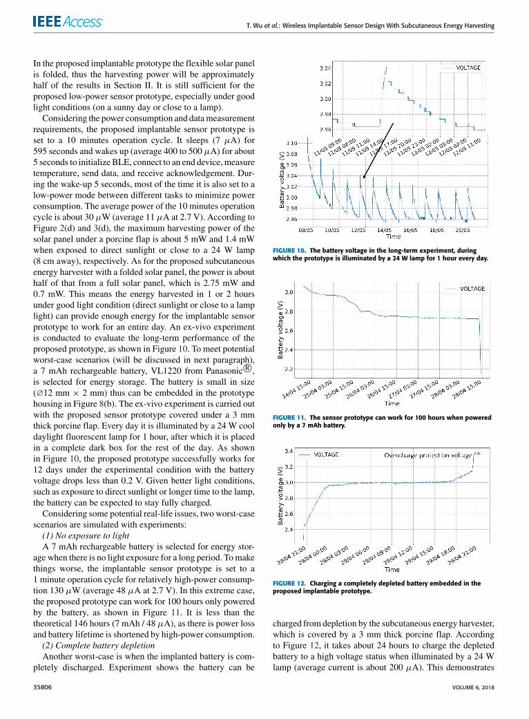
In the proposed implantable prototype the flexible solar panelis folded, thus the harvesting power will be approximatelyhalf of the results in Section II. It is still sufficient for theproposed low-power sensor prototype, especially under goodlight conditions (on a sunny day or close to a lamp).
Considering the power consumption and datameasurementrequirements, the proposed implantable sensor prototype isset to a 10 minutes operation cycle. It sleeps (7 µA) for595 seconds and wakes up (average 400 to 500 µA) for about5 seconds to initialize BLE, connect to an end device, measuretemperature, send data, and receive acknowledgement. Dur-ing the wake-up 5 seconds, most of the time it is also set to alow-power mode between different tasks to minimize powerconsumption. The average power of the 10 minutes operationcycle is about 30 µW (average 11 µA at 2.7 V). According toFigure 2(d) and 3(d), the maximum harvesting power of thesolar panel under a porcine flap is about 5 mW and 1.4 mWwhen exposed to direct sunlight or close to a 24 W lamp(8 cm away), respectively. As for the proposed subcutaneousenergy harvester with a folded solar panel, the power is abouthalf of that from a full solar panel, which is 2.75 mW and0.7 mW. This means the energy harvested in 1 or 2 hoursunder good light condition (direct sunlight or close to a lamplight) can provide enough energy for the implantable sensorprototype to work for an entire day. An ex-vivo experimentis conducted to evaluate the long-term performance of theproposed prototype, as shown in Figure 10. To meet potentialworst-case scenarios (will be discussed in next paragraph),a 7 mAh rechargeable battery, VL1220 from Panasonic R©,is selected for energy storage. The battery is small in size(∅12 mm × 2 mm) thus can be embedded in the prototypehousing in Figure 8(b). The ex-vivo experiment is carried outwith the proposed sensor prototype covered under a 3 mmthick porcine flap. Every day it is illuminated by a 24 W cooldaylight fluorescent lamp for 1 hour, after which it is placedin a complete dark box for the rest of the day. As shownin Figure 10, the proposed prototype successfully works for12 days under the experimental condition with the batteryvoltage drops less than 0.2 V. Given better light conditions,such as exposure to direct sunlight or longer time to the lamp,the battery can be expected to stay fully charged.
Considering some potential real-life issues, two worst-casescenarios are simulated with experiments:(1) No exposure to lightA 7 mAh rechargeable battery is selected for energy stor-
age when there is no light exposure for a long period. Tomakethings worse, the implantable sensor prototype is set to a1 minute operation cycle for relatively high-power consump-tion 130 µW (average 48 µA at 2.7 V). In this extreme case,the proposed prototype can work for 100 hours only poweredby the battery, as shown in Figure 11. It is less than thetheoretical 146 hours (7 mAh / 48 µA), as there is power lossand battery lifetime is shortened by high-power consumption.(2) Complete battery depletionAnother worst-case is when the implanted battery is com-
pletely discharged. Experiment shows the battery can be
FIGURE 10. The battery voltage in the long-term experiment, duringwhich the prototype is illuminated by a 24 W lamp for 1 hour every day.
FIGURE 11. The sensor prototype can work for 100 hours when poweredonly by a 7 mAh battery.
FIGURE 12. Charging a completely depleted battery embedded in theproposed implantable prototype.
charged from depletion by the subcutaneous energy harvester,which is covered by a 3 mm thick porcine flap. Accordingto Figure 12, it takes about 24 hours to charge the depletedbattery to a high voltage status when illuminated by a 24 Wlamp (average current is about 200 µA). This demonstrates
35806 VOLUME 6, 2018

T. Wu et al.: Wireless Implantable Sensor Design With Subcutaneous Energy Harvesting
TABLE 1. Comparisons of implantable medical systems with subcutaneous energy harvesting.
that the proposed sensor prototype can be restarted even whenbattery is depleted.
In Table 1, the comparison between different implantablebiomedical systems with energy harvesting is presented.
VI. CONCLUSIONThis paper proposes a subcutaneous solar energy harvesterfor implantable biomedical devices. The electrical propertiesof a flexible solar panel under a porcine flap are studied undersunlight and artificial light sources. The output power of thesubcutaneous solar panel varies from tens of microWatts to afew milliWatts depending on irradiance levels. An optimalposition for the subcutaneous energy harvester is found tobe between the neck and shoulder, which is demonstratedby ex-vivo experiments. To evaluate the real-life applicationof the harvester, a wireless implantable sensor prototypeis presented. The prototype incorporates a power manage-ment circuit, a temperature sensor, a BLE module and a7 mAH rechargeable battery, which are all embedded in atransparent silicone housing. The sensor system is set to a10 minutes operation cycle with power of 30 µW, whichcan be self-powered by the subcutaneous solar energy har-vester. The long-term operation, including two worst-casescenarios (no exposure to light and battery depletion), aredemonstrated by ex-vivo experimental results. In the future,the work can be improved by dedicated solar panels that aremore suitable for subcutaneous light conditions. The potentialflexible supercapacitor can be used to replace the battery,which can further reduce the volume of the implantableprototype.
REFERENCES[1] U. E. Bauer, P. A. Briss, R. A. Goodman, and B. A. Bowman, ‘‘Prevention
of chronic disease in the 21st century: Elimination of the leading pre-ventable causes of premature death and disability in the USA,’’ Lancet,vol. 384, no. 9937, pp. 45–52, 2014.
[2] A. Kiourti and K. S. Nikita, ‘‘A review of in-body biotelemetry devices:Implantables, ingestibles, and injectables,’’ IEEE Trans. Biomed. Eng.,vol. 64, no. 7, pp. 1422–1430, Jul. 2017.
[3] A. Haeberlin et al., ‘‘Successful pacing using a batteryless sunlight-powered pacemaker,’’ Europace, vol. 16, no. 10, pp. 1534–1539, 2014.
[4] S. Vaddiraju, M. Kastellorizios, A. Legassey, D. Burgess, F. Jain, andF. Papadimitrakopoulos, ‘‘Needle-implantable, wireless biosensor forcontinuous glucose monitoring,’’ in Proc. 12th Int. Conf. WearableImplant. Body Sensor Netw. (BSN), Cambridge, MA, USA, Jun. 2015,pp. 1–5.
[5] R. Muller et al., ‘‘A minimally invasive 64-channel wireless µECoGimplant,’’ IEEE J. Solid-State Circuits, vol. 50, no. 1, pp. 344–359,Jan. 2015.
[6] M. A. Hannan, S. Mutashar, S. A. Samad, and A. Hussain, ‘‘Energyharvesting for the implantable biomedical devices: Issues and challenges,’’Biomed. Eng. Online, vol. 13, no. 1, p. 79, 2014.
[7] T. Wu, F. Wu, J.-M. Redouté, and M. R. Yuce, ‘‘An autonomous wire-less body area network implementation towards IoT connected healthcareapplications,’’ IEEE Access, vol. 5, pp. 11413–11422, 2017.
[8] A. B. Amar, A. B. Kouki, and H. Cao, ‘‘Power approaches for implantablemedical devices,’’ Sensors, vol. 15, no. 11, pp. 28889–28914, 2015.
[9] S. Stoecklin, A. Yousaf, T. Volk, and L. Reindl, ‘‘Efficient wireless power-ing of biomedical sensor systems for multichannel brain implants,’’ IEEETrans. Instrum. Meas., vol. 65, no. 4, pp. 754–764, Apr. 2016.
[10] D. H. Kim et al., ‘‘In vivo self-powered wireless transmission using bio-compatible flexible energy harvesters,’’ Adv. Funct. Mater., vol. 27, no. 25,p. 1700341, 2017.
[11] Q. Zheng et al., ‘‘Biodegradable triboelectric nanogenerator as a life-timedesigned implantable power source,’’ Sci. Adv., vol. 2, no. 3, p. e1501478,2016.
[12] A. N. Bashkatov, E. A. Genina, V. I. Kochubey, and V. V. Tuchin, ‘‘Opticalproperties of human skin, subcutaneous and mucous tissues in the wave-length range from 400 to 2000 nm,’’ J. Phys. D, Appl. Phys., vol. 38, no. 15,p. 2543, 2005.
VOLUME 6, 2018 35807

T. Wu et al.: Wireless Implantable Sensor Design With Subcutaneous Energy Harvesting
[13] E. Moon, D. Blaauw, and J. D. Phillips, ‘‘Subcutaneous photovoltaicinfrared energy harvesting for bio-implantable devices,’’ IEEE Trans.Electron Devices, vol. 64, no. 5, pp. 2432–2437, May 2017.
[14] S. Ayazian, V. A. Akhavan, E. Soenen, and A. Hassibi, ‘‘A photovoltaic-driven and energy-autonomous CMOS implantable sensor,’’ IEEE Trans.Biomed. Circuits Syst., vol. 6, no. 4, pp. 336–343, Aug. 2012.
[15] A. Haeberlin et al., ‘‘The first batteryless, solar-powered cardiac pace-maker,’’ Heart Rhythm, vol. 12, no. 6, pp. 1317–1323, 2015.
[16] L. Bereuter et al., ‘‘Energy harvesting by subcutaneous solar cells: A long-term study on achievable energy output,’’ Ann. Biomed. Eng., vol. 45, no. 5,pp. 1172–1180, 2017.
[17] A. F. Demir et al., ‘‘In vivo communications: Steps toward the next gen-eration of implantable devices,’’ IEEE Veh. Technol. Mag., vol. 11, no. 2,pp. 32–42, Jun. 2016.
[18] Q. H. Abbasi, A. A. Nasir, K. Yang, K. A. Qaraqe, and A. Alomainy,‘‘Cooperative in-vivo nano-network communication at terahertz frequen-cies,’’ IEEE Access, vol. 5, pp. 8642–8647, 2017.
[19] W. Y. Toh, Y. K. Tan, W. S. Koh, and L. Siek, ‘‘Autonomous wearablesensor nodes with flexible energy harvesting,’’ IEEE Sensors J., vol. 14,no. 7, pp. 2299–2306, Jul. 2014.
[20] A. Dionisi, D. Marioli, E. Sardini, and M. Serpelloni, ‘‘Autonomous wear-able system for vital signs measurement with energy-harvesting module,’’IEEE Trans. Instrum. Meas., vol. 65, no. 6, pp. 1423–1434, Jun. 2016.
[21] T. Wu, J.-M. Redoute, and M. R. Yuce, ‘‘Subcutaneous solar energyharvesting for self-powered wireless implantable sensor systems,’’ in Proc.40th Annu. Int. Eng. Med. Biol. Conf., Honolulu, HI, USA, Jul. 2018.
[22] V. Salas, E. Olias, A. Barrado, and A. Lazaro, ‘‘Review of the maximumpower point tracking algorithms for stand-alone photovoltaic systems,’’Sol. Energy Mater. Sol. Cells, vol. 90, no. 11, pp. 1555–1578, 2006.
[23] J. Ahmad, ‘‘A fractional open circuit voltage based maximum power pointtracker for photovoltaic arrays,’’ in Proc. 2nd Int. Conf. Softw. Technol.Eng. (ICSTE), San Juan, PR, USA, vol. 1, Oct. 2010, pp. V1-247–V1-250.
[24] Y.-J. Hung et al., ‘‘High-voltage backside-illuminated CMOS photo-voltaic module for powering implantable temperature sensors,’’ IEEEJ. Photovolt., vol. 8, no. 1, pp. 342–347, Jan. 2018.
TAIYANG WU (S’16) received the B.E. degreefrom Southeast University, Nanjing, China,in 2014. He is currently pursuing the Ph.D.degree in electrical and computer systems engi-neering withMonash University. His main areas ofresearch interest are energy harvesting, biomedicalsensor network, and IoT connected healthmonitor-ing applications.
JEAN-MICHEL REDOUTÉ (M’09–SM’12) rec-eived the M.S. degree in electronics from the Uni-versity College of Antwerp, Belgium, in 1998,the M.Eng. degree in electrical engineering fromthe University of Brussels, Belgium, in 2001, andthe Ph.D. degree in design of EMI resisting analogintegrated circuits in 2009. In 2001, he startedworking at Alcatel Bell, Antwerp, where he wasinvolved in the design of analog microelectroniccircuits for telecommunications systems. In 2005,
he joined ESAT-MICAS laboratories, University of Leuven, as a Ph.D.Research Assistant. In 2009, he started working at the Berkeley WirelessResearch Center, University of California at Berkeley, Berkeley, as a Post-Doctoral Scholar. In 2010, he joinedMonash University as a Senior Lecturer.His research interests include mixed-signal integrated circuit design, electro-magnetic compatibility, biomedical (integrated and non-integrated) circuitdesign, and radio-frequency integrated circuit design.
MEHMET RASIT YUCE (S’01–M’05–SM’10)received the M.S. degree in electrical andcomputer engineering from the University ofFlorida, Gainesville, FL, USA, in 2001, and thePh.D. degree in electrical and computer engi-neering from North Carolina State University,Raleigh, NC, USA, in 2004. He was a Post-Doctoral Researcher with the Electrical Engineer-ing Department, University of California at SantaCruz, in 2005. He was an Academic Member with
the School of Electrical Engineering and Computer Science, Universityof Newcastle, Callaghan, NSW, Australia, until 2011. In 2011, he joinedMonash University, Australia, where he is currently an Associate Professorwith the Department of Electrical and Computer Systems Engineering.
He has authored the books Wireless Body Area Networks (2011) andUltra-Wideband and 60 GHz Communications for Biomedical Applications(2013). His research interests include wearable devices, Internet-of-Thingsfor healthcare, wireless implantable telemetry, wireless body area network,bio-sensors, integrated circuit technology dealing with digital, analog andradio frequency circuit designs for wireless, biomedical, and RF applications.He has published over 150 technical articles in the above areas. He receivedthe NASA Group Achievement Award in 2007 for developing an SOItransceiver, the Best Journal Paper Award in 2014 from the IEEEMicrowaveTheory and Techniques Society, and the Research Excellence Award fromthe Faculty of Engineering and Built Environment, University of Newcastle,in 2010. He is a Topical Editor for the IEEE SENSORS JOURNAL and a GuestEditor for the IEEE JOURNAL OF BIOMEDICAL AND HEALTH INFORMATICS in 2015.
35808 VOLUME 6, 2018


