Investigation of Equestrian Arena Surface Properties and ...clok.uclan.ac.uk/8563/1/Holt Dani Final...
172
Investigation of Equestrian Arena Surface Properties and Rider Preferences by Danielle Holt A thesis submitted in partial fulfilment for the requirements for the degree of MSc (by Research) at the University of Central Lancashire April 2013
Transcript of Investigation of Equestrian Arena Surface Properties and ...clok.uclan.ac.uk/8563/1/Holt Dani Final...

Investigation of Equestrian Arena Surface Properties
and Rider Preferences
by
Danielle Holt
A thesis submitted in partial fulfilment for the requirements for the degree of MSc (by Research) at the University of Central Lancashire
April 2013

Declaration
i
Student Declaration
Concurrent registration for two or more academic awards I declare that while registered as a candidate for the research degree, I have not been
a registered candidate or enrolled student for another award of the University or other academic or professional institution
____________________________________________________________________ Material submitted for another award I declare that no material contained in the thesis has been used in any other
submission for an academic award and is solely my own work ____________________________________________________________________ Collaboration Where a candidate’s research programme is part of a collaborative project, the thesis
must indicate in addition clearly the candidate’s individual contribution and the extent of the collaboration. Please state below:
Signature of Candidate ______________________________________________________ Type of Award MSc by Research School Sport, Tourism and the Outdoors

Abstract
ii
A synthetic surface with inconsistent mechanical properties is considered to be a
risk factor for injury in horses. Research has been carried out involving the use of
surface testing equipment predominantly on race tracks to improve knowledge on
surface properties that are implicated in a higher risk of injury. The preference of the
rider is also an important consideration and has previously affected the choice of
surface. The study investigated the effect of moisture, compaction and drainage on
different equine arena sand and fibre surfaces and also the preferences of riders
regarding surface properties. A Biomechanical Hoof Tester (maximum load, load rate,
range of horizontal acceleration, vertical deceleration, shear modulus and hysteresis),
Clegg Hammer (hardness) and Torque Wrench (traction) were used as a suite of
mechanical tests to investigate the effects of three different moisture levels (6.83 ±
1.01%, 17.45 ± 0.76%, 21.19 ± 0.9%) and three different surface densities (1.624±0.008
g/cm3, 1.690±0.016 g/cm3, 1.705±0.019 g/cm3) on four equine sand and fibre arena
surfaces. In order to test numerous surfaces under the same controlled conditions,
eight test boxes (L100cm x W98cm x D20cm) were made, where four surfaces were laid
on gravel and four laid on permavoid units, an innovative drainage system. The
responses of riders regarding preferred amount of traction and ‘way of going’ were
established using a survey. Traction significantly increased (P<0.001) with increasing
moisture level however, was not affected by the compaction treatments or drainage
type. Hardness and hysteresis were significantly (P<0.001) higher at a low moisture
content and vertical deceleration was significantly (P<0.001) higher at a low and medium
moisture content. The surfaces laid on gravel also generated significantly (P<0.001)
higher values. Maximum load, load rate and shear modulus were significantly (P<0.001)
lower at a low moisture level. The range of horizontal acceleration was significantly
(P<0.001) higher when the surfaces had a medium moisture content. The measured
variables were significantly (P<0.001) higher when the surfaces had a high density
except for the shear modulus. The respondents of the survey preferred a ‘moderate
amount of traction’ and a ‘firm surface with a bit of give’. The surfaces with a medium
(17.45%) to high (21.19%) moisture content when laid on permavoid had the most
favourable results when taking into account all of the measured parameters. The low
moisture content (6.83%) was associated with a higher energy loss and vertical
deceleration on impact with the surface especially when the surfaces had a high density,
thereby increasing the risk of injury. The lower maximum loads measured at this
moisture content would also have a negative effect on performance. The study has
shown that surface properties of different sand and fibre arena surfaces can be altered
through not only changing the amount of moisture and compaction but also drainage
type and surface composition.

Contents
iii
Section Title Page number
Preliminaries Declaration i Preliminaries Abstract ii Preliminaries Contents iii Preliminaries Acknowledgements ix
1.0 Literature Review 1 1.1 Introduction 1 1.2 Risk factor for injury 1 1.3 Hoof surface interaction 2 1.4 Surface types 5
1.4.1 Sand with additives 5 1.4.2 Other surface types 6 1.4.3 Wax 6 1.4.4 Drainage systems 7 1.5 Surface properties 8
1.5.1 Surface hardness 8 1.5.2 Shear resistance 11 1.5.3 Surface density 12 1.5.4 Surface moisture content 13 1.6 Current guidelines 14
1.6.1 Athlete preferences 16 1.7 Surface Testing 17
1.7.1 Clegg Hammer 18 1.7.2 Torque Wrench 18 1.7.3 Biomechanical Hoof Tester 19 1.8 Aims and Objectives 21 2.0 Materials and Methods 22
2.0.1 Ethical considerations and Health and Safety 22 2.0.2 Study design 22 2.1 Field Based Study 23
2.1.1 Materials 23 2.1.2 Developmental and pilot work 26 2.1.3 Experimental protocol 27 2.1.4 Sampling technique 27 2.1.5 Statistical Analysis 35 2.2 Questionnaire Based Study 37
2.2.1 Rider preferences survey 37 2.2.2 Pilot work 37 2.2.3 Experimental protocol 37 2.2.4 Statistical Analysis 39 3.0 Results 40 3.1 Field Based study 40
3.1.1 Maximum impact force used to compact the surfaces 44 3.1.2 Traction 45 3.1.3 Surface hardness 47 3.1.4 Maximum load on impact 51 3.1.5 Load rate 55 3.1.6 Range in horizontal acceleration 58 3.1.7 Maximum vertical deceleration 61 3.1.8 Shear modulus 64 3.1.9 Hysteresis 66
3.1.10 Summary of results 72 3.2 Questionnaire Based study 74
3.2.1 Preferred amount of traction 76 3.2.2 Preferred way of going 76 3.2.3 Training, competition and preferred surfaces 78

Contents
iv
3.2.4 Summary of results 82 4.0 Discussion 83 4.1 Traction 83 4.2 Hardness 86 4.3 Maximum load and load rate 89 4.4 Horizontal and vertical acceleration 93 4.5 Surface damping 96 4.6 Ideal treatment combinations 99 4.7 Conclusion 102 5.0 References 104 6.0 Appendices I
Appendices Appendix I: Ethics II Appendices Appendix II: Risk assessments XXIV Appendices Appendix III: Rider preference survey XXXV Appendices Appendix IV: Composition testing XLIV Appendices Appendix V: Timetable for data collection XLVI Appendices Appendix VI: Block diagram formula XLIX

Contents
v
Figures Figure Title Page
number 1.0 Literature Review 1.1 Stages of the stance phase. 4 2.0 Materials and Methods
2.0.1 Study design 22 2.1.1 A surface testing device which shows two axes of motion and the
configuration of the instrumentation on the test machine. 28
2.1.2 Front panel image from LabVIEW. 31 2.1.3 A print screen from LabVIEW of the raw data signals and noise
signal interruption. 32
3.0 Results 3.1 Field Based Study results
3.1.1 The mean bulk density of the surfaces in each test box. 43 3.1.2 Mean (±SE) maximum impact force used by all the researchers to
compact the surfaces to create a medium compaction level and high compaction level.
44
3.1.3 Interactions between mean traction values for moisture level and test box number.
46
3.1.4 Mean (±SE) hardness values for the first drop of the Clegg Hammer according to test box number and compaction level.
47
3.1.5 Mean (±SE) hardness values for the fourth drop of the Clegg Hammer according to test box number and compaction level.
48
3.1.6 The mean (±SE) range in hardness values from drop1-4 according to moisture and compaction level.
49
3.1.7 The range in hardness values from drop 1-4 obtained from the different text boxes for all the treatments applied.
50
3.1.8 The mean (±SE) maximum load for the different drop numbers, compaction and moisture levels.
51
3.1.9 Interactions between mean (±SE) maximum load values for moisture level and test box number.
52
3.1.10 Interactions between mean (±SE) maximum load values for compaction level and test box number.
53
3.1.11 The range in maximum load values obtained from each of the test boxes for all of the treatments.
54
3.1.12 A Load- time graph obtained during the first drop of the Biomechanical Hoof Tester. B Load- time graph obtained during the third drop of the Biomechanical Hoof Tester
55
3.1.13 The mean (± SE) load rate for the different drop numbers, compaction and moisture levels.
56
3.1.14 Interactions between mean load rates for moisture level and test box number.
57
3.1.15 The range in load rate values obtained from each of the test boxes for all of the treatments.
58
3.1.16 The mean (± SE) range of horizontal acceleration for the different drop numbers, compaction and moisture levels.
59
3.1.17 Interactions between mean ranges of horizontal acceleration for moisture level and test box number.
60
3.1.18 The horizontal acceleration range obtained from each of the test boxes for all of the treatments.
61
3.1.19 The mean (± SE) maximum vertical deceleration for the different drop numbers, compaction and moisture levels.
62
3.1.20 Interactions between mean (±SE) maximum vertical deceleration for moisture level and drainage type.
63

Contents
vi
3.1.21 The range in maximum vertical deceleration values obtained from each of the test boxes for all of the treatments.
63
3.1.22 Correlation between surface hardness recorded with the Clegg Hammer (drop 2, 3, 4) and maximum vertical deceleration recorded with the Biomechanical hoof Tester (drop 1, 2, 3) for the low moisture and high compaction level.
64
3.1.23 The median shear modulus of the surfaces for the different drop numbers, compaction and moisture levels.
65
3.1.24 The range in shear modulus values obtained from each of the test boxes for all of the treatments.
65
3.1.25 The mean (± SE) hysteresis for the different drop numbers, compaction and moisture levels.
67
3.1.26 Interactions between mean hysteresis for moisture level and test box number.
68
3.1.27 Interactions between mean hysteresis for compaction level and test box number.
69
3.1.28 The range in hysteresis values obtained from each of the test boxes for all of the treatments.
70
3.1.29 A, B, C
Load-displacement curves for TB1 and TB5 according to moisture and compaction level recorded during the first drop of the Biomechanical Hoof Tester.
71
3.2 Questionnaire Based Study Results 3.2.1 Proportion of riders from the different disciplines responding to the
survey. 74
3.2.2 The number of responses relating to the preferred amount of traction a surface provides.
76
3.2.3 The number of responses relating to the preferred way of going a surface provides.
77
3.2.4 Training, competition and preferred surface types of the riders who responded to the survey.
78
3.2.5 The number of riders who train indoors (n=30) or outdoors (n=200) and in which conditions the surface provides them with an optimal performance on their horse.
80

Contents
vii
Plates Plate Title Page
number 2.0 Materials and Methods
2.1.1 Test boxes 1-4 situated on top of the limestone chipping 24 2.1.2 Test boxes 5-8 situated on top of the permavoid units 25 2.1.3 The elephant foot tamper being used to compact the first layer of
sand 25
2.1.4 Measuring the bulk density of the reference surface 26 2.1.5 The Biomechanical Hoof Tester which has been constructed so
that it is possible to mount it to a vehicle in order to change the impact site
30
2.1.6 Clegg Impact Testing device 33 2.1.7 The Torque Wrench and the studded shoe fitted to the base of the
weights 34
3.0 Results 3.1.1 Test box eight (sand and low fibre and low wax on permavoid)
under a low level of compaction. 43

Contents
viii
Tables Table Title Page
number 2.0 Materials and Methods
2.1.1 Sub-base and surface combinations for the different test boxes 25 2.2.1 The questions used in the survey 38 3.0 Results 3.1 Field Based Study results
3.1.1 Surface composition 40 3.1.2 Particle size distribution of each surface 40 3.1.3 Sub-base and surface combinations for the different test boxes 41 3.1.4 Mean moisture contents according to moisture level 41 3.1.5 Mean bulk density of all the surfaces under different compaction
levels. 42
3.1.6 Mean (±SE) air temperature above and below the surface during data collection.
45
3.1.7 Mean (±SE) traction according to test box and moisture content. 46 3.1.8 Mean (±SE) maximum load according to test box and moisture
content. 53
3.1.9 Mean (±SE) maximum load according to test box and compaction level.
54
3.1.10 Mean (±SE) load rate according to test box and moisture content. 57 3.1.11 Mean (±SE) range of horizontal acceleration according to test box
and moisture content. 60
3.1.12 Mean (±SE) hysteresis according to test box and moisture content. 68 3.1.13 Mean (±SE) hysteresis according to test box and compaction level. 69 3.1.14 Summary of the main findings for how the different parameters
were affected by different moisture and compaction levels. 72
3.2 Questionnaire Based Study results 3.2.1 Different level of riders and how they were categorised according to
competition level. 75
3.2.2 Chi-square test for the training, competition and preferred surface types.
79
3.2.3 Chi-square test for the conditions in which the indoor or outdoor training surface provides the best performance.
81
3.2.4 Summary of questionnaire results. 82

Acknowledgements
ix
I would like to start by saying thank you to Myerscough College for funding my MSc and providing me with the opportunity to work with some amazing people. I would like to say thank you very much to my supervisory team including Sarah Hobbs, Jaime Martin, Charlotte Brigden and my two advisors Alison Northrop and Andy Owen. The project would not have been possible without your help and expertise with data collection, statistics, LabView, written work and your endless explanations. Thank you for being patient with me and I have learnt so much from all of you and feel priveliged to have worked with you. Thank you to Glen Crook for building the test boxes and helping with the construction work and during my data collection. Thank you to David Elphinstone who has always been there for advice and for teaching me the correct way to paint an office! Thank you to Em Blundell for showing me the ropes, helping with the data collection and using your ‘elephant foot tamping’ skills. Thank you to Laura Dagg for pointing me in the right direction at the start. We had some great times in the research office and wish you could have stayed longer! Thank you to Jimmy May and his team for helping with the construction work. Thank you to the yard and events team for putting up with my daily digging and tamping before data collection. A special thanks goes to Keni. I could not have asked for any more support and patience from you during this busy year. You have always been there for me and kept my spirits up and I appreciate your help shifting and compacting nearly 3 tonnes of sand with me x Thank you to my friends and family for your perpetual support and believing in me. Even though I have not managed to see you all as much as I had liked, I know you have always been there for me x Finally thanks to the horses I have and work with .....At the end of the day, that is why I am here in the first place!! You are the ultimate stress-buster and excellent listeners! X

Chapter 1.0 Literature Review
1
1.0 LITERATURE REVIEW
1.1 Introduction
Synthetic arena surfaces are widely used throughout the equine industry for
training and competition. The surface a horse works on has been documented as a
risk factor for injury amongst other variables such as conformation and type of training
and discipline (Chateau et al., 2009; Crevier-Denoix et al., 2009; Peterson et al., 2012;
Reiser et al., 2000; Riggs, 2010; Robin et al., 2009; Setterbo et al., 2009; Williams et
al., 2001). Research on surfaces has been carried out involving the use of horses
fitted with devices such as accelerometers and mechanical testing equipment to
improve knowledge on how surface properties affect the hoof-surface interaction
(Chateau et al. 2009; Peterson et al., 2008). The work has predominantly focused on
race tracks due to the higher injury rate associated with this discipline (Chateau et al.
2009; Peterson et al., 2008; Ratzlaff et al., 1997; Robin et al. 2009).
The injuries sustained by three show jumpers at the 2004 Olympic Games in
Athens were attributed to the studs used and the resulting surface interaction and has
initiated further work on equine arena surfaces. The Fédération Equestre
Internationale (FEI) is funding a long term research project led by Dr Lars Roepstorff
investigating the influence of surface characteristics on the orthopaedic health of
horses (van Weeren, 2010). The published results obtained from different studies have
at times been conflicting and inconsistent which is possibly due to differences in
experimental design, discipline, analytical approach, injury type and case definitions
and therefore further investigations are warranted (Ratzlaff et al., 1997; Setterbo et al.,
2011). The development of such research will contribute towards developing an
optimal arena surface that combines performance and consistency with safety
(Peterson et al., 2012).
1.2 Risk factors for injury
The concern that a surface may be a source of injury in humans arose in the
late 1960s when the use of artificial playing surfaces constructed using synthetic or
manufactured materials became more popular (Nigg and Yeadon, 1987). The
synthetic surfaces were associated with a higher injury rate and negative effects on the
locomotor system in comparison with naturally occurring surfaces. The increasing use
of artificial surfaces in the equine industry has also been associated with an increase in
the occurrence of injuries. Human surfaces have been researched extensively since
the work published by Nigg and Yeadon (1987) and a more recent study has shown

Chapter 1.0 Literature Review
2
that injury risks in humans can be reduced and performance enhanced, if training and
competition is performed on a suitable surface that meets safety requirements (Swan
et al., 2009).
Research conducted on several major racetracks in the United States of
America has led to dirt surfaces being replaced with synthetic all weather tracks, which
has resulted in a significant reduction in catastrophic breakdown of horses (Peterson et
al., 2012; Setterbo et al., 2011). The breakdowns recorded on Arlington race course in
the United States of America reduced from 22 in 2006 on a dirt surface to 13 in 2007
when the track had been replaced with a synthetic Polytrack (Liebman, 2007).
Synthetic surface properties have shown to be more consistent than dirt in a study by
Setterbo et al. (2011) which may support why a lower injury rate has been recorded.
Dirt surfaces are more dependent on maintenance procedures than synthetic surfaces
in relation to keeping the surface properties consistent (Kai et al., 1999; Setterbo et al.,
2011). Uneven surfaces with varying moisture content, density and composition result
in irregular forces acting upon the horse, which are associated with a greater risk of
injury (Kai et al., 1999; Murray et al., 2010a; Ratzlaff et al.,1997; Riggs, 2010).
A surface with the ability to remain uniform throughout all climatic conditions is
therefore considered essential and an epidemiological study by Murray et al. (2010b)
suggested a consistent surface appears to have a protective effect against lameness in
dressage horses. A sand based surface appeared to be associated with the greatest
risk for lameness when used at first and was less prone to cause lameness as the
horse continued to work on the surface (Murray et al., 2010a). The reduced risk of
injury over a period of time has been attributed to the process of adaptive hypertrophy
where the bones and soft tissue within the limbs gradually become conditioned to the
interface used. It was of interest however, that Murray et al. (2010a) still found at least
77% of British Dressage riders that responded to a survey had a sand based surface.
The finding suggests that there are other influential factors when selecting the right
arena surface such as finances available which demonstrates that further
investigations on controlling and understanding surface properties are warranted.
1.3 Hoof-surface interaction
The equine distal limb is subjected to repetitive shocks and vibrations during the
stance phase of locomotion due to rapid deceleration of the limb which transmits
shockwaves through the hoof and surrounding structures (Barrey et al., 1991; Chateau
et al., 2010; Gustås et al., 2006a). The amplitude of the deceleration peak is partly
dependent on the type of surface that the distal limb is colliding with (Gustås et al.,

Chapter 1.0 Literature Review
3
2006a). Large deceleration peaks and high loading rates are experienced within the
limb during impact with firm surfaces, which may contribute to subchondral bone
damage and increase the risk of injury (Johnston and Back, 2006; Radin 1973; Parkin
et al., 2004).
A link between shock and vibration and subchondral bone damage was
established by Radin et al. (1973) where the knee joints of rabbits stiffened after
impulsive loading, which represented changes consistent with degenerative joint
disease. Loading has been defined as the vector sum of the external forces and
moments acting on a body by Nigg and Yeadon (1987) and more recently, van Weeren
(2010) made a similar description of the application of forces to a structure in an equine
related research article. The characteristic forces acting on the horse are the ground
reaction forces, which are generated by the locomotion activity in combination with the
forces exerted by the surface (Brosnan et al., 2009). The ground reaction forces may
at times exceed tolerable limits during repetitive loading or directional overloading
which will cause micro-trauma and eventually lead to equine musculoskeletal disorders
(van Weeren, 2010). The forces and accelerations experienced within the distal limb
will also be affected by the point of the stride cycle that the limb is in. A stride cycle
consists of a stance phase, followed by a swing phase which can be further subdivided
(Figure 1.1, p. 4):
1) Preimpact is the phase immediately before the hoof hits the ground;
2) Impact is the first third of stance during which a ground reaction force is generated
which is characterised by prominent peak decelerations and high loading rates
(Brosnan et al., 2009; Gustås et al., 2006b). The magnitude of hoof deceleration and
ground reaction forces on impact have been found to be significantly affected by the
speed at which the horse is travelling (Gustås et al., 2006b; Thomason and Peterson,
2008) and also by the type of surface (Gustås et al., 2006a). The impact can be further
divided into primary and secondary impact. The primary impact (Figure 1.1 A) is
associated with high accelerations and low forces when the hoof impacts the surface
(Thomason and Peterson, 2008). The vertical deceleration is higher than the
horizontal deceleration due to the ratio of the forward and downward hoof movement
(Gustås et al., 2006b). The horizontal deceleration represents the braking forces of the
hoof in order to resist sliding according to Reiser et al. (2000). The secondary impact
(Figure 1.1 B) is characterised by much higher forces and minimal acceleration when
the mass of the horse collides with the leg as it becomes implanted on the ground
(Barrey et al., 1991; Thomason and Peterson, 2008);

Chapter 1.0 Literature Review
4
3) Support (Figure 1.1 C) is initiated when the weight of the body is evenly applied to
the leg and the hoof flattens out before continuing to rotate through to the next part of
the stance phase (Reiser et al., 2000; Thomason and Peterson, 2008). At this stage,
the vertical and horizontal accelerations have diminished and the highest vertical forces
are experienced whilst the horizontal forces increase in the latter part of the support
phase (Thomason and Peterson, 2008);
4) Breakover or roll over (Figure 1.1 D) occurs when the hoof lifts at the heels and rolls
from the ground which causes propulsive forces in the cranial and caudal direction as
the horse moves forward (Reiser et al., 2000; Thomason and Peterson, 2008);
5) Post breakover immediately follows where the hoof and digit flex rapidly and forms
the start of the swing phase (Thomason and Peterson, 2008).
Figure 1.1 Stages of the stance showing the differences in acceleration (red) and
ground reaction force (blue) among the stages. When the blue arrow is tilted, it
indicates that both vertical and horizontal components of the ground reaction force are
present. The arrow shows the direction in which the ground is pushing the horse.
Adapted from Peterson et al. (2012).
The stance phase appears to be a greater focus in current research when
compared to the swing phase. At this stage, the horse will experience high forces and
loads that are significantly affected by the surface type and properties (Barrey et al.,
1991; Drevemo and Hjertén, 1991; Gustås et al., 2006a; Reiser et al., 2000; Peterson
et al., 2008, 2012). The distal limb is structured in such a way so the forces exerted
during impact with the ground during natural movement do not exceed tolerable limits.
A B C D

Chapter 1.0 Literature Review
5
The physical demands placed on horses whilst being ridden however, can be extensive
and the forces may surpass acceptable loads which predisposes the horse to injury.
1.4 Surface types
The surface composition affects the hoof surface interaction and this has been
demonstrated by Barrey et al. (1991) where impact intensity on a number of different
equine surfaces was related to density and composition of the surface. There are
many different types of equine surfaces on the market however the manufacture and
selection of composition materials have been largely based on empirical evidence and
marketing factors (Setterbo et al., 2009). Different surfaces are available for various
uses which can be sold as individual components or mixed with additives according to
the requirements of the buyer and the intended use of the arena (van Weeren, 2010).
The climate is also a major consideration when choosing a surface and variations in
the weather throughout the United Kingdom (UK) and across the world means that a
surface ideal for one location may be less suitable for another (Riggs, 2010). The base
materials used mainly comprise sand, rubber or woodchip (Murray et al., 2010a). The
additives can include polypropylene fibres of varying lengths, rubber, fabric pieces and
binding polymer which is more commonly referred to as a wax and the entire surface is
supported on an engineered foundation or drainage system.
1.4.1 Sand with additives
Arena manufacturers recommend using very fine angular or sub-angular silica
sand to provide a firm consolidated surface of approximately 15cm in depth (Andrews
Bowen Limited, 2012). Sand, which naturally has low elasticity, is commonly used for
arenas and it is thought that the addition of polypropylene fibres and binding polymers
adds rebound and reduces compaction (Baker and Richards, 1995; Setterbo et al.,
2011).
The use of fibres in a sand based surface appears to have many advantages
however, high quality fibres that are dust-free are expensive. The geographical
location of the arena may affect the ability to source certain materials and it may only
be feasible to utilise surfaces that are locally available. There are many training
centres for trotters in France that use sand beaches for training for example due to
their close proximity and also because they are considered as good training surfaces
specific to competition (Chateau et al., 2010).
The addition of fibres is thought to create a root-like structure and has been
shown to increase the stability and drainage of winter games pitches in a study by

Chapter 1.0 Literature Review
6
Baker and Richards (1995), which is important in areas where there is a high amount of
traffic. A synthetic turf surface that contained polypropylene fibre, rubber infill and a
shock attenuation pad has also been found to decrease the loading magnitude in
certain regions of the foot in comparison to natural grass whilst athletes were playing
football (Ford et al., 2006). The change was attributed to the synthetic surface having
a lower stiffness and more elasticity than the natural grass, making the synthetic
surface a more favourable choice when aiming to reduce the incidence of injuries.
The way in which sand responds to additives is also dependent on particle size,
which affects the bulk density, water retention and dustiness of a surface (Barrey et al.,
1991). There is currently very limited research on equine sand based surfaces despite
the fact that they have been identified as a risk factor for injury (Gustås et al., 2006a;
Murray et al., 2010a). Additional studies to educate the industry further on arena
construction and reducing the incidence of injury would be extremely valuable.
1.4.2 Other surface types
Rubber and woodchip based surfaces are also in common use within the
industry and are usually cheaper to buy than premium sand-based surfaces (Murray et
al., 2010a). The high response rate (n=11363) from an arena survey sent to British
Dressage members enabled Murray et al (2010a) to conclude that 49% of surfaces in
use were sand and rubber and 6% were woodchip. The remaining surfaces in use
consisted of sand (15%), sand and pvc (13%), wax coated substrate (6%), grass (5%)
and the remaining 6% was not specified (Murray et al., 2010a).
The rubber and woodchip can cause problems with the incidence of injury
where the consistency of the surfaces reduces if they are not routinely and correctly
maintained. The unpredictable surface conditions could negatively influence gait
stability and could explain why Murray et al. (2010a) suggested that wood chip used as
a primary surface increased the occurrence of slipping in horses. A woodchip layer
below the primary surface however provides more cushioning by significantly reducing
hardness and increasing shock absorbency as found by Drevemo and Hjertén (1991).
1.4.3 Wax
Wax coated sand and fibre surfaces are also offered on the equine market
however, this is usually at a premium because the properties allow for long term
performance under a variety of conditions (Bridge et al., 2010). Competition centres or
arenas in high use often benefit from such a combination. Paraffin wax is commonly
used as a binding polymer which has cohesive properties and is usually blended with

Chapter 1.0 Literature Review
7
mineral oil and other additives to stabilise the polymer and optimise melting points and
viscosity (Bridge et al., 2010).
The results obtained during the survey by Murray et al. (2010a) suggested a
waxed surface remains more uniform in a variety of weather conditions than sand and
woodchip surfaces and was also thought to contribute to a lower incidence of lameness
and injuries. A wax coated surface also required less maintenance to remain stable
and suggests that the mechanical properties do not fluctuate as much as an un-waxed
surface (Murray et al., 2010a). An all weather waxed track produced more favourable
results in comparison to a crushed sand track where loading forces within the distal
limb whilst trotting significantly reduced (Chateau et al., 2009; Crevier-Denoix et al.,
2009; Robin et al., 2009) Research that will contribute to the development of an
affordable surface that remains consistent throughout all weather conditions, when
suitably maintained would be a very beneficial addition to the industry (Murray et al.,
2010a).
1.4.4 Drainage systems
The drainage is also an essential factor to consider when constructing an arena
and will ultimately affect the quality of the footing laid above. An effective system will
prevent excess water from gathering and encourage hydraulic conductivity of the
substrate which is the ability of the surface to transmit water and therefore drain
(Peterson et al., 2010). The surface type and drainage system installed plays a large
role on the water holding capacity of a surface where maintaining the correct
distribution of air-filled and capillary porosity is essential. Adequate drainage must be
installed to ensure the synthetic surface recovers quickly from rainfall however a
surface that is too permeable may have a reduced moisture retaining ability during dry
periods. The geographical location of the arena is also an important consideration
when choosing a drainage system due to the different amounts of rainfall.
Limestone gravel and perforated pipes dug further into the ground are
commonly used beneath the surface and a geotextile membrane to aid drainage and
more recently specialised drainage systems have been developed such as the
Equaflow™ system (Andrews Bowen Limited, 2012) and Ebb and Flow system
(Strathoof Managebodems, 2012). The innovative designs allow water to be removed
and added to the surface with the use of a storage tank and automatic pump to
regulate and maintain the moisture content. The newer drainage systems are costly
however and are not widely used at present. The Equaflow™ system was used under
the footing at the recent 2012 Olympic Games which may advance its use throughout

Chapter 1.0 Literature Review
8
the industry. Detailed technical guidelines exist on how to construct a sub-base system
that is suitable for professional synthetic turf fields (Brock International, 2012). The
type of drainage to use within equine arenas has not been substantiated by scientific
evidence and is usually installed according to the manufacturer’s recommendations.
1.5 Surface Properties
The surface type and drainage system affect the properties of a surface, which
will affect the hoof-surface interaction and therefore performance of the horse (Barrett
et al., 1997; Burn, 2006; Burn and Usmar, 2005; Ford et al., 2006; Northrop et al.,
2012; Peterson et al., 2012). Performance and safety of a substrate represent two of
the most important concepts surrounding surfaces and therefore, a combination of
properties that creates a surface that is consistent, offers sufficient support to prevent
injury and assists in achieving an optimal performance is highly desirable (Baker and
Canaway, 1993).
A surface that is considered to assist with an optimal performance of the horse
is usually associated with a greater risk of injury whereas a surface that has shock
absorbing properties will be of detriment to performance (Chateau et al., 2010; Durá et
al., 1999). The balance between safety and performance is highly dependent upon
surface properties that relate to variables such as hardness, stiffness, shear resistance,
surface density and the ability of the substrate to retain moisture. The mechanical
properties have changed under different environmental conditions such as weather and
the amount of traffic in studies on human sports surfaces and therefore are an
important consideration for equine arena surfaces (Brosnan et al., 2009; Goodall et al.,
2005; Spring and Baker, 2006).
1.5.1 Surface hardness
Surface hardness is considered to be a large factor affecting the playing quality
of sports surfaces and the risk of injury (Baker et al., 2001; Canaway, 1992; Ford et al.,
2006). Surface hardness affects factors such as ball rebound behaviour and player-
surface interaction, which has led to extensive studies in order to develop surfaces that
provide an optimum performance (Baker et al., 2001; Brosnan et al., 2009; Ford et al.,
2006; Goodall et al., 2005; Spring and Baker, 2006). The hardness of a surface is a
function of a number of physical properties including stiffness and resilience according
to Baker and Canaway (1993) and has been defined by Nigg and Yeadon (1987) as
the resistance of a material against penetration of a defined object under defined
pressure.

Chapter 1.0 Literature Review
9
The stiffness of a surface is the ratio of applied force to the amount of deflection
of a surface according to Nigg and Yeadon (1987). A material such as concrete would
be described as very stiff whereas a surface with low stiffness such as rubber foam
would deflect a considerable amount under an applied load and would be considered
compliant (Baker and Canaway, 1993). The surface stiffness that is experienced by
the horse may vary according to the size and duration of the load. A horse landing
after a jump for example would create a much larger load and experience a different
hoof-surface interaction in comparison to a Dressage horse performing piaffe that
involves a longer stance duration. The resilience is the ratio of the mechanical energy
after impact compared to the mechanical energy before impact (Baker and Canaway,
1993; Nigg and Yeadon, 1987). A trampoline for example would be described as a
very resilient structure because there is a relatively low amount of energy lost on
impact (Baker and Canaway, 1993).
The hardness of a surface has also been identified as a risk factor for injury in
horses and consequently, the effects of surface hardness on locomotion of mainly
racehorses and trotters has been investigated (Chateau et al., 2009; Ratzlaff et al.,
1997). Horses have been instrumented with accelerometers, piezoelectronic
transducers and ultrasonic devices to improve understanding on the locomotor forces
exerted on different surface types with varying hardness (Chateau et al., 2009; Crevier-
Denoix et al., 2009; Ratzlaff et al., 1997; Robin et al., 2009). Only recently,
mechanical devices have been used to quantify the effect of arena maintenance on the
firmness of a surface (Tranquille et al., 2012; Walker et al., 2012). It is important to
develop literature on surface properties measured using testing equipment to provide
quantitative baseline data that is not affected by the individual variation of horses.
A softer surface is associated with better shock absorbing characteristics where
the forces experienced by the horse are decreased, however it may reduce the
efficiency of locomotion (Barret et al., 1997; Chateau et al., 2009). There will be higher
demands placed on the musculoskeletal system because the surface is lacking
resilience where the ability to absorb the impact mechanical energy is higher (Baker
and Canaway, 1993; Brosnan et al., 2009). The propulsion from the elastic energy
stored by the tendons within the distal limb will also be lower as a result, which may
hasten the onset of muscular fatigue (Barret et al., 1997; Murray et al., 2010a). The
effort required from the muscles to achieve the same movement is amplified and
consequently increases the risk of injury (Murray et al., 2010a).
The increased effort to sustain the same speed on a more compliant all weather
waxed track was reflected in results obtained by a research group from D’Alfort

Chapter 1.0 Literature Review
10
Veterinary School, France when compared to a crushed sand track (Chateau et al.,
2009, 2010; Crevier-Denoix et al., 2009; Robin et al., 2009). A decrease in stride
length and an increase in stride frequency were reported in the trotters used. A study
by Setterbo et al. (2009) conversely found no significant difference between stride
frequency and speed whilst investigating ground reaction forces on different surfaces
including dirt, synthetic and turf tracks. The sample sizes used for all the studies were
small, which may explain the different findings. The surface types used also differed,
suggesting that further investigations are warranted on different surfaces being
measured under the same conditions.
The shock absorbing characteristics of a compliant surface may also protect the
horse from injury. The loads and forces experienced when the distal limb impacts a
yielding surface are modulated by spreading the collision over the longest period of
time as possible instead of being a nearly instantaneous event (Chateau et al., 2010;
Dunlop, 2000; Thomason and Peterson, 2008; Setterbo et al., 2011). The ground
reaction forces are consequently reduced. The sequencing of the leg motions in the
different gaits and the anatomic adaptations of the horse also increases the time of
collision which reduces mechanical stress (Dunlop, 2000; Thomason and Peterson,
2008).
The locomotion of trotters have been documented by Chateau et al. (2009)
where an all-weather waxed track demonstrated better shock absorbing characteristics
when compared with a crushed-sand track. The stance duration was the same on both
surfaces however the maximum impact force was experienced sooner on the crushed
sand track. Impact forces are forces which reach their maximal magnitude less than 50
milliseconds after first contact with the surface in humans, which demonstrates how
quickly the horse is required to dampen the forces (Nigg and Yeadon, 1987). A study
on humans by Mcmahon and Greene (1979) however, observed a longer ground
contact time on softer surfaces which consequently reduced running speed. The
impact time in a small sample of horses (n=4) during a more recent study was also
significantly higher on an uncompacted dry sand surface in comparison to wet sand
which demonstrates that the load is spread out over a longer period of time (Chateau et
al., 2010). The degree of surface compaction appears to be a factor affecting the
results between the studies and necessitates further research.
The timing between deformation of the surface under load and when the load is
removed is critical and if it is too soon, it will represent additional forces that must be
dissipated by the limbs (Ratzlaff et al., 1997). Deceleration of the equine limb during
impact is affected by surface type and the amount of deformation. Deceleration on an

Chapter 1.0 Literature Review
11
all weather waxed track was more progressive and significantly reduced by
approximately 50% when compared to crushed sand (Chateau et al., 2009). The
findings obtained by Crevier-Denoix et al. (2009) demonstrated the maximal tendon
force and maximal longitudinal braking force also significantly reduced on a waxed
track in comparison to a crushed sand track. The soft tissues of the limb will not have
been required to dampen as many vibrations on the all weather waxed surface which
could explain the lower forces observed. Maximum forces, load rates, maximum
accelerations, and tendon forces were also lower for synthetic racing surfaces than
traditional dirt surfaces, indicating that engineered surfaces have potential for injury
reduction (Setterbo et al., 2009, 2011).
1.5.2 Shear resistance
Shear resistance or traction relates to the frictional forces that are generated in
the horizontal plane when the limb impacts the surface. Friction has been described by
Medoff (1995) as a combination of mechanical interlocking and adhesion between two
interfaces. It is necessary for the horse to apply shear stress to the surface in order to
produce traction and therefore a propulsive movement. The cohesive properties of the
surface that are affected by other factors such as wax or moisture content will
determine the amount of torque or rotational force that the horse will experience whilst
travelling on the surface and may create a risk factor for injury (Baker and Firth, 2002;
Brosnan et al., 2009; Goodall et al., 2005).
Hoof slip of the leading limb on jump landing, a parameter that is affected by the
shear characteristics of a surface has been investigated by Orlande et al. (2012) on
two arena surfaces with different wax contents (3% and 10%). The higher wax content
significantly reduced hoof slip and this was also supported with higher traction values.
The surface with 10% wax was considered to be more consistent however and there
was also less variation in the jumping technique observed between the horses used
(Orlande et al., 2012). Higher friction between the hoof and ground has shown to
increase the impact shock, resulting in higher mechanical stress and risk of injury
(Gustås et al., 2006a). The degree of traction required to achieve various movements
such as turning at speed for show jumping or the pirouette in dressage without being of
detriment to the horse has not been reported. The demands being placed on the
musculoskeletal system differ according to the discipline of the horse and the amount
of traction required may vary which makes it difficult to quantify.
A lower shear resistance could account for the reduced locomotion efficiency
observed in horses on an all weather waxed surface compared to a crushed sand track

Chapter 1.0 Literature Review
12
during recent studies (Chateau et al., 2009, 2010; Crevier-Denoix et al., 2009; Robin et
al., 2009). The all weather surface was associated with lower forces and decelerations
in the horizontal plane which suggests that the crushed sand track may have been
firmer and provided more traction. It is possible to reinforce this claim further where
Gustås et al. (2006a) states that higher friction increases the shockwaves that transmit
through the distal limb. A significantly shorter braking duration on the crushed sand
surface in comparison to the all weather waxed track could also support the higher
amount of shear resistance that the surface offered.
To minimise the effects of the surface properties on the locomotor stresses of
the horse, the properties should have low impact forces and accelerations in the
horizontal and vertical planes and a relatively low amount of energy lost on impact
(Ratzlaff et al., 1997). The impact resistance or hardness of a surface is generally
negatively correlated with energy loss when the hoof impacts the surface however,
which may prove to be challenging during the selection of a surface. It has also been
reported by Setterbo et al. (2011) that an ideal, safe surface should have a relatively
low energy loss along with low hardness which is correlated with deceleration and is
difficult to achieve. The synthetic racing surface used in the study by Setterbo et al.
(2011) appeared to have both of these qualities however when the surface was under a
certain level of compaction.
1.5.3 Surface density
A study by Brosnan et al. (2009) investigated the effects of compaction on the
hardness and traction of a baseball playing surface. A quadratic relationship was
reported by Brosnan et al. (2009) where greater compaction yielded increases in
surface hardness and traction. Traction values represent the peak amount of
horizontal force required to initiate movement (Baker and Canaway, 1993; Brosnan et
al., 2009). Baker et al. (1998) found increases in surface hardness on cricket pitches
to be a function of increased soil bulk density, which is defined as the surface mass per
unit volume and rises with a higher amount of compaction. Rotational traction
measured by Baker et al. (1998) was also significantly affected by soil density, which
may be due to differences in the size of the air spaces between the surface particles
and therefore the degree of shear resistance. The surface density will also be affected
by the amount of traffic working over the surface and a suitable maintenance regime
should be used to loosen the top surface layer in order to prevent undesirable amounts
of compaction.

Chapter 1.0 Literature Review
13
The presence of organic matter has been found to strongly influence bulk
density in a study by Baker et al. (1998) and Saffih-Hdadi et al. (2009) found organic
matter reduced bulk density and consequently the ability of the soil to compact. A
similar effect may be expected with the addition of fibres or other additives to a sand
based equine surface however this has not been documented. Plastic fibres are
commonly added to the soil of many professional football pitches in order to stabilise
and strengthen the rootzone (Spring and Baker, 2006).
The addition of polypropylene and polyurethane fibres to a sand and turf
football surface has been examined by Spring and Baker (2006) where turf strength
had a positive correlation with the amount of fibres added and this was reflected in
higher traction values. There was no reference to the amount of surface compaction
however. Hardness was found to significantly reduce with an increase in fibre content
and possibly demonstrates a lower bulk density according to the findings of Brosnan et
al. (2009). The surfaces studied by Spring and Baker (2006) and Brosnan et al. (2009)
were different along with the apparatus used to measure the traction which will have
affected the traction values recorded. The results obtained by Saffih-Hdadi et al (2009)
suggested the susceptibility of a range of soil types to compaction was also found to be
affected by moisture content.
1.5.4 Surface Moisture Content
The moisture content of a substrate is considered to be the most important
variable to measure because it strongly influences other surface properties (Goodall et
al., 2005; Peterson et al., 2008). A level of increase in moisture content improves
particle adherence and consequently shear resistance, which provides more stability
(Chateau et al., 2010; Murray et al., 2010a; Ratzlaff et al., 1997). There is very limited
research on particle adherence when a surface has been saturated, which is when the
pore spaces between the particles cannot absorb any more water. A high correlation
was found between impact force and moisture content on a race track studied by
Ratzlaff et al. (1997), which was predominantly medium to very course sand. The
outcome suggests that a low (4%) and high (12%) moisture content could be
detrimental in terms of injury because these values were associated with higher forces.
The mean and peak impact force in the horizontal and vertical planes has been found
to be significantly higher on wet beach sand (19%) in comparison to uncompacted, dry
beach sand (3%) by Chateau et al. (2010), which only support some of the findings of
Ratzlaff et al. (1997).

Chapter 1.0 Literature Review
14
A study by Brosnan et al. (2009) found conflicting information where a reduction
in moisture content was related to an increase in surface hardness of a non-turfed
basepath, which is considered to generate higher forces and possibly supports why
higher forces were recorded by Ratzlaff et al. (1997) at lower moisture contents. The
relative density was high when the observations were made by Brosnan et al. (2009)
and the high hardness values could be explained by an increase in density reducing
surface porosity and increasing the particle strength, which decreases soil water
infiltration and holding capacity (Saffih-Hdadi et al., 2009). The hardness of skinned
infield plots consisting of crushed rock has also been found to be negatively correlated
with moisture content by Goodall et al. (2005). The water content for the optimum
performance of sand surfaces has been suggested to be between 8% and 17% and
alterations in this will affect other parameters such as hardness and shear resistance of
the surface (Barrey et al., 1991; Ratzlaff et al., 1997). A small variation (5.5%) in
moisture content between two beach sand tracks that were used in a study by Chateau
et al. (2010) was sufficient to cause a significant difference between the peak vertical
deceleration at the onset of the stance phase.
The current literature relating to the effects of moisture and surface density on
surface properties needs to be strengthened by performing further experiments under
field conditions on equine surfaces commonly in use (Chateau et al., 2010). A greater
understanding would be gained on possible combinations of moisture and relative
density that may be of detriment to the horse in terms of injury and performance. The
findings would also inform arena construction and management practices in order to
avoid surface properties considered to be unfavourable.
1.6 Current Guidelines
Sports associations have begun to develop safety policies in relation to the
suitability and safety of the playing surfaces (Swan et al., 2009). The use of a ground
safety checklist for human sports is a mandatory requirement of insurers where factors
such as intended use of the surface, frequency of use, unevenness, debris, surface
hardness and traction are taken into consideration (Swan et al., 2009). Sports
including football, cricket and hockey utilise the checklist because the governing bodies
have a duty of care for the health and safety of participants (Swan et al., 2009). Sports
hall floors, running tracks, tennis courts, and gymnastic crash mats are more examples
of surfaces that are required to exceed minimum shock attenuation criteria established
by sports governing bodies and other agencies (Shorten and Himmelsbach, 2002).

Chapter 1.0 Literature Review
15
Sporting bodies such as the International Association of Athletics Federations
(IAAF), Union of European Football Associations (UEFA) and International Hockey
Federation (FIH) have laid down specifications for the resilience of playing surfaces.
The testing methods in use include the Berlin Athlete and the Stuttgart Athlete which
are widely used to determine safety standards for playground surfaces and floors. The
standard artificial Berlin Athlete simulates the impact of an 80-90kg person doing a
vertical jump and has been accepted as the best practical solution for measuring the
shock absorbing properties of a sports surface (Durá et al., 1999). The Stuttgart
Athlete was found to be the most precise and accurate method to provide information
on the deformation of a surface by Dunlop (2000). A peak deceleration test is another
procedure used by many sports governing bodies where the peak value is used to
determine the shock absorption of surfaces in relation to the comfort and safety of
users (Carré and Haake, 2004).
The Clegg Hammer is commonly used to assess peak deceleration and has
been used to assess the hardness of playing surfaces, which is considered to be a
good indicator of playing performance and construction profiles (Baker et al., 2001).
The most common practice is to establish a minimum strength requirement in terms of
Clegg Impact Value (CIV) for specified moisture contents in order to create a single
value acceptance/rejection criterion (Clegg, 2012). Studded boot apparatus is also
widely used to provide information on the traction of a playing surface because it
affects the ability of the player to change direction (Fifa, 2009). There are published
performance requirements for games pitches where preferred and acceptable ranges
of traction and clegg impact values inform current management regimes for football,
rugby and hockey (Baker et al., 2007; Fifa, 2009). The existing standards for the Clegg
Hammer were revised by Baker et al. (2007) using a different drop mass. The CIVs
obtained from a heavier Clegg Hammer mass of 2.25kg was subject to less variation
than the lighter mass of 0.5kg which was originally used to create the performance
standards (Baker et al., 2001, 2007).
The safety policies are yet to expand across equestrian disciplines in the same
magnitude that they have throughout human sports. The rules of horse racing
regarding surface safety have been altered however in 2009 (British Horseracing
Authority, 2012). It is now a compulsory requirement to take several TurfTrax™ Going
Stick measurements per mile for each fixture, which are then published alongside the
official going description (British Horseracing Authority, 2012). The Going Stick is a
device that provides an objective numerical reading on the penetration and shear
resistance of the surface. Research on race track surfaces using other testing

Chapter 1.0 Literature Review
16
methods is predominantly being performed in America. A research team led by
Professor Mick Peterson have been using high technology equipment to study the
mechanical properties of race tracks (Peterson et al., 2008; Peterson and Mcilwraith,
2008). Some of the properties associated with increasing the risk of injury in race
horses have consequently been identified, which enables the best management
procedures to be followed.
The research on equine surface characteristics is of great significance yet
specified guidelines and policies to ensure a safe working environment are not a
compulsory prerequisite and the management of surfaces is based on anecdotal
manufacturer’s recommendations (Setterbo et al., 2009). The Fédération Equestre
Internationale (FEI) regulations for equestrian events at the Olympic Games in 2012
stated that horses must only be trained and compete on suitable surfaces which must
be “designed and maintained to reduce factors that could lead to injuries” (FEI, 2011,
pg5). The FEI (2011) also stated that “particular attention must be paid to the
preparation, composition and upkeep of surfaces”. The exact surface composition and
preparation to be used for the different disciplines was not clearly defined and the
guidelines provided are potentially open to interpretation.
1.6.1 Athlete Preferences
There is controversy at times between what is considered to be a safe surface
and the preference of the athlete regarding surface type. A study by Durá et al. (1999)
involved asking non-elite sportsmen to jump as high as possible from a 42cm height
onto surfaces with varying compliance. The shock absorbing capacity
recommendation for a multipurpose indoor surface of 51-53% was considered to be too
excessive because the athletes felt it had a negative impact on performance (Durá et
al., 1999). A harder surface is negatively proportional to an increase in energy loss,
which optimises performance however it increases the risk of injury, which is why the
guidelines are installed (Ratzlaff et al., 1997).
Horse racing is another example where conflict has arisen between safety and
performance of surfaces used (Liebman, 2007). The newer synthetic tracks, which
have reduced the incidence of fatalities are associated with fractionally slower race
times and maintenance problems and have caused varied opinions on what is
considered to be the best surface for racing (Liebman, 2007; Peterson et al., 2012;
Setterbo et al., 2009). The show jumpers at the Greenwich test event in 2011 criticised
the all-weather wax surface where the softer going appeared to have a negative impact
on the performance of some of the horses (Hart, 2011). There is evidence that the

Chapter 1.0 Literature Review
17
demands of riders at elite level are influencing the type of surfaces used for competition
(Hart, 2011). The type of surface to use however is not being substantiated by
scientific evidence, which poses a challenge when trying to formulate industry
guidelines on equine arena construction (Murray et al., 2010a).
The importance of taking the preferences of football players regarding surface
compliance into account has been recognised by Baker et al. (2007). A player
questionnaire is often used prior to a game in order to determine the most relevant
performance limits which may improve acceptance of the current guidelines (Baker et
al., 2007). The implementation of safety checklists for human sports may be
responsible for the significant decrease in the number of injury related insurance claims
recently made (Swan et al., 2009). The equine industry must be made aware of the
positive impact the safety guidelines have had on the various human sport
associations. The development of equine industry standards on surface properties that
take into account the preferences of the rider, will ensure consistency among surfaces
under a range of conditions, optimise performance and minimise the risk of injury
(Setterbo et al., 2009).
1.7 Surface testing
Sport surfaces have been commonly assessed in an objective manner with
respect to technical specifications such as thickness and temperature dependency;
cost factors including installation and maintenance; sport functional properties such as
hardness, traction and performance and; safety considerations such as measures to
prevent injury. The latter two are important aspects to test and consider from a
biomechanical point of view. The testing of surfaces requires reliable quantitative
information describing the biomechanical and mechanical properties of a surface in
order for the research to be of significance to the equine industry (Peterson and
Mcilwraith, 2008).
There have been major innovations throughout the last decade in the
development of surface testing devices, which allow the quantitative assessment of
human sport surfaces (Swan et al., 2009). The mechanical devices have only recently
been adapted and developed for use on equine surfaces and they remove the need to
use horses during the experimental protocol. The delay in this development could
explain the absence of industry guidelines regulating the construction of arenas and
specifications on the optimal surface type to enhance performance and reduce the risk
of injury (Attwood and Barron, 2009; Peterson et al., 2008; Weishaupt, 2010; Wheeler,
2006; White, 2010). The equipment currently in use for human and equine surfaces do

Chapter 1.0 Literature Review
18
have drawbacks however, and do not always simulate the true forces and
accelerations experienced by the limbs on impact (Chateau et al., 2009; Peterson and
Mcilwraith, 2008; Ratzlaff et al., 1997; Reiser et al., 2000).
A simple hoof impact model devised by Reiser et al. (2000) considers only the
vertical loading components of the limb and does not take into account the shear forces
in the horizontal plane (Peterson et al., 2012). A track testing device has been
developed by Ratzlaff et al. (1997) to simulate the impact of the equine hoof so that the
dynamic surface properties under different moisture levels relating to force, energy
return and impact resistance could be identified. The device however, only calculates
the forces and accelerations in the vertical plane when the load cell is dropped onto the
surface. The results did however, enable Ratzlaff et al. (1997) to establish the trend
between force and moisture content of the race tracks studied.
1.7.1 The Clegg Hammer
The Clegg Hammer developed by Dr Baden Clegg in the late 1960s is another
example of a drop hammer device which is the most widely used method for measuring
the hardness of human sports surfaces (Baker et al., 2007; Clegg, 1976, 2012). The
Clegg Hammer along with other drop devices such as penetrometers have low load
rates and also only take into account the impact resistance of a surface in the vertical
plane. The values obtained with the drop devices are still considered to be useful
however, in providing information on the cushion layer and compressive forces of the
substrate (Baker and Canaway, 1993; Setterbo et al., 2011).
The relationship between the surface hardness of cricket pitches recorded with
different Clegg Hammer drop weights (0.5kg vs 2.25kg) and ball rebound has been
investigated (Baker et al., 2001). The results suggested that a heavier hammer of
2.25kg should be used or alternatively the drop height increased to increase the energy
of impact and therefore reliability of the readings. The apparatus has also proven to be
a useful tool at estimating the strength of compacted soils in a study by Kahn et al.
(1995). The accelerometer which is rigidly fastened to the hammer allows the
deceleration versus time curve upon impact with the soil to be determined and provides
information regarding the soil strength or stiffness.
1.7.2 The Torque Wrench
A Torque Wrench or traction apparatus is used to provide information on the
traction or shear resistance of a surface and has been commonly used to assess
human sports surfaces (Brosnan et al., 2009; Canaway and Bell, 1986). Traction

Chapter 1.0 Literature Review
19
alongside hardness is considered to be frequently linked with injury risk and therefore
is an important surface property to consider (Canaway and Bell, 1986). The equipment
takes into account the forces experienced in the horizontal plane, however it will not
provide acceleration data or the impact forces present in the vertical plane. Results
obtained with the apparatus can have a high degree of variability according to the
conditions under which data was collected which makes comparisons between studies
challenging (Twomey et al., 2011). The traction equipment is consequently used in
conjunction with other surface testing devices such as the Clegg Hammer to also
provide a wider data set on the mechanical properties of the surface (Brosnan et al.,
2009).
The testing devices currently in use undoubtedly improve knowledge on how a
surface reacts to various conditions and allow repeatable measurements but as
mechanical surface testing devices develop, the equipment must accurately simulate
the hoof-surface interaction. The need to measure horizontal forces and accelerations
with impact devices has been demonstrated by Gustås et al. (2001) because the
variables are an important factor in the attenuation of the impact. A more predictive
model than those used in previous epidemiological studies (Ratzlaff et al., 1997; Reiser
et al., 2000) will enhance further understanding on the optimal surface properties for
training and competition. There are important aspects that must be incorporated by the
model according to van Weeren (2010) which include 1) the surface characteristics
being described comprehensively and unequivocally and 2) the surface being
measured reliably and accurately.
1.7.3 The Biomechanical Hoof Tester
The drawbacks of the current models and testing equipment were recognised
by Peterson et al. (2008). A more advanced, specialised system known as the dual-
axis synthetic hoof drop hammer or Biomechanical Hoof Tester has consequently been
designed. The device has a hoof-shaped impactor that reproduces the hoof
acceleration and force on impact in vertical and horizontal directions which provides
realistic quantification of the surface properties under a range of conditions (Peterson
et al., 2008). The measured parameters are expected to be related to the performance
of the horse and the stage at which the synthetic hoof impacts the ground is one of the
most critical phases of the gait cycle and considered a risk factor for injury (Peterson et
al., 2012).

Chapter 1.0 Literature Review
20
It is possible to use the Biomechanical Hoof Tester in a realistic competition
environment which will improve the use of the tool if the data can provide relevant
information on the properties of surfaces used by many riders. The use of such
equipment also removes the inherent variability related to horses and improves the
reliability of measurements that can be performed in the field or laboratory environment
(Chateau et al., 2009; Gustås et al., 2006a, b; Setterbo et al., 2011). Wide variations in
acceleration peaks between successive strides within the same trial have been
observed in horses of similar body mass and under the same management practices
(Barrey et al. 1991; Gustås et al. 2004, 2006a, b; Ratzlaff et al., 2005).
There are three published studies to date involving the use of the Hoof Tester
where the effect of maintenance including harrowing and watering has been assessed
on race track and arena surface properties (Peterson and Mcilwraith, 2008; Tranquille
et al., 2012; Walker et al., 2012). The equipment does have drawbacks including cost
and the initial set up being time consuming however, once testing commences data
can be recorded efficiently. The data set for the Biomechanical Hoof Tester must be
developed to improve understanding on how different surface properties affect the
hoof-surface interaction.
The current literature on equine arena surfaces involved testing pre-established
surfaces where there was a lack of control of testing conditions. The absence of a
study which characterises the components of a surface is a significant obstacle to
improved performance and safety as stated by Peterson et al. (2012). Moisture
content and arena usage are large factors that appear to affect surface properties
based on the findings of current literature. A study investigating the effects of moisture
and surface density of equine arena surfaces under controlled conditions using the
testing devices discussed would therefore be a valuable contribution to the industry. A
study that also considers the preferences of riders regarding surface properties would
also be beneficial to inform management practices. The data obtained on the
mechanical characteristics of a surface will improve understanding on conditions
influencing the equine locomotory system and how properties can be altered according
to rider preferences.

Chapter 1.0 Literature Review
21
1.8 Aims and Objectives
There are two aims of the study:
Aim 1: To measure the effect of moisture, density and drainage on the mechanical
properties of four equine sand and fibre arena surfaces.
Objective 1: Surface testing equipment including a Biomechanical Hoof Tester, Clegg
Hammer and Torque Wrench were used to measure the response of the surface to a
range of treatments. The surfaces were prepared under three different densities, three
moisture contents and also on two different sub-bases including gravel and permavoid.
Aim 2: To establish the preferences of riders regarding surface type and preparation.
Objective 2: The preference of riders regarding surface type and properties was
determined with the use of a survey. The survey was available to complete at
Myerscough College and also online in order to reach a range of riders across the UK.
The alternative hypothesis for the entire study states there will be a significant change
in surface properties under different testing conditions and a significant difference
between the preferences of riders according to level and discipline.

Chapter 2.0 Materials and Methods
22
2.0 MATERIALS AND METHODS
2.0.1 Ethical Considerations and Health and Safety
The study was approved by the ethics committee (reference number: BuSH
057) at University of Central Lancashire and did not require the use of any horses or
animals (Appendix I). Risk assessments (Appendix II) were formulated for the use of
all the equipment and every effort was made to ensure the working environment was
safe with the lowest risk possible to all the researchers involved. The participants of
the arena survey remained anonymous and were able to withdraw at anytime.
2.0.2 Study Design
The study was split into two parts according to the aims; a field based (2.1) and
questionnaire based study (2.2). A Biomechanical Hoof Tester simulating equine hoof
impact, a Clegg Hammer and a Torque Wrench were used to study the effect of three
different moisture contents and three different densities levels on dynamic surface
properties, which created nine unique treatments to be applied during the field based
study (Figure 2.0.1). Experiments were performed on four different surfaces that were
reproduced twice to investigate the effects of a traditional drainage system and
permavoid units used for the Equaflow drainage system on surface properties.
Figure 2.0.1 Study design. L=Low, M=Medium and H=High
The rider preference survey (Appendix III) was constructed for the
questionnaire-based study and available to complete online for 11 weeks in order to
establish the preferences of riders regarding surface type and preparation.
Moisture
Density
Test days
Limestone TB 1-4
L M
H M H L M L
H
H M L
1 2 3
L M H
H M L H M L H M L
1 3 2
Permavoid TB 5-8 Drainage

Chapter 2.0 Materials and Methods
23
2.1 Field Based Study
2.1.1 Materials
Synthetic sand and fibre arena surfaces (n=4, 3 waxed and 1 un-waxed) that
are currently on the market were used for the study. High quality sub-angular silica
sand that is suitable for equestrian use was the main component of all the surfaces and
additives included different quantities of polypropylene fibres and binding polymer. A
200g sample of each of the surfaces was separated in order to calculate the
composition of the surfaces using the method that has been outlined by Peterson et al.
(2012) (Appendix IV).
The sand and fibre components were dried in separate pre-weighed trays in the
oven at 102˚C for 24 hours after being separated from the binding polymer in order to
calculate the moisture content and the actual percentage of sand, fibre and wax. A
dried sand sample of 100g was then used to calculate the particle size distribution
using the same size sieves as Chivers and Aldous (2003), which included 1mm,
500µm, 355µm, 250µm, 180µm, 150µm, 125µm, 90µm and 63µm.
In order to test a range of surfaces under the same controlled conditions, eight
test boxes (L100cm x W98cm x D20cm) were made and situated next to the a research
test track at Myerscough College (Plate 2.1.1). The dimensions of the test boxes were
selected according to the Boussinesq equation as stated by Das (2008) in order to
reduce the boundary effect on the measured parameters. It is expected that the
pressure within the surface caused at impact will be less than 2.5% at a horizontal
distance that is twice that of the diameter of the impacting device (Das, 2008). The
equation assumes circular pressure bulbs under the loaded area and that the surface is
elastic however synthetic surfaces are elastoplastic in nature and Setterbo et al. (2011)
recognised the pressure bulbs on impact are more elliptical where the pressure is
concentrated more along the axis of loading. There is little published work surrounding
the boundary effects on the values obtained with impact devices and therefore taking
the Boussinesq equation into consideration is important.
The surface depth of 15 cm was selected according to the findings of Setterbo
et al. (2011) where little or no change in the measured parameters would be found if
more substrate was to be added. The choice of surface depth is also a
recommendation of the manufacturer (Andrews Bowen Limited, 2012). A small
Perspex window was installed in the test boxes to allow the researchers to observe any
visual changes in the surface properties (Plate 2.1.1). Geotextile membrane was

Chapter 2.0 Materials and Methods
24
secured to the base of all the test boxes (n=8) prior to installing the surfaces in order to
simulate an arena setting.
There were two different types of drainage systems used under the test boxes
to determine the effects of hydraulic conductivity on the measured surface properties.
The systems included a traditional drainage system, which was situated under test box
one to four (Plate 2.1.1), and permavoid units, which were under test box five to eight
(Plate 2.1.2). The traditional drainage system consisted of 30mm limestone chipping
that had been compacted down with a wacker plate to create a 120mm layer above the
levelled earth. A retaining wall was built to prevent the chippings from moving (Plate
2.1.1). The permavoid consists of plastic units with a depth of 85mm and have more
commonly been used under pavements to aid drainage (Permavoid Limited, 2012).
The units create the main components of an Equaflow™ system and are considered to
provide sustainable irrigation and a consistent footing (Permavoid Limited, 2012). The
test boxes were filled with 238 kg of the four different types of surface to a depth of
15cm so each surface was prepared in two test boxes to be placed above each of the
drainage systems (Table 2.1.1).
Plate 2.1.1 Test boxes 1-4 situated on top of the limestone chipping. Note the oval Perspex windows installed
100cm 98cm
20cm

Chapter 2.0 Materials and Methods
25
Plate 2.1.2 Test boxes 5-8 situated on top of the permavoid units.
Table 2.1.1 Sub-base and surface combinations for the different test boxes.
Test box number Sub-base and surface combination 1 Gravel, Surface 1 (waxed) 2 Gravel, Surface 2 (un-waxed) 3 Gravel, Surface 3 (waxed) 4 Gravel, Surface 4 (waxed) 5 Permavoid, Surface 1 (waxed) 6 Permavoid, Surface 2 (un-waxed) 7 Permavoid, Surface 3 (waxed) 8 Permavoid, Surface 4 (waxed)
The boxes were filled at 3cm increments, levelled and compacted with an
“elephant foot tamper” which is a square weight attached to a long pole to simulate an
arena being constructed (Plate 2.1.3). The final 3cm was levelled with a rake but not
compacted and this represented the low density in preparation for the protocol to
commence. The surfaces were installed and prepared approximately one week prior to
the first day of data collection and kept covered with tarpaulin to restrict climatic effects.
Plate 2.1.3 The “elephant foot tamper” being used to compact the first layer of sand.

Chapter 2.0 Materials and Methods
26
2.1.2 Developmental and Pilot Work
To validate the use of the surface testing equipment on the test boxes, the suite
of mechanical tests were performed on three different equine arenas at Myerscough
College prior to data collection. The correct amount of water to add to the surfaces
was determined through pilot testing where different volumes of water were added to a
surface that had been placed in a test box and was not being used for actual data
collection. The volumes were selected in order to achieve three moisture contents that
replicated a low, moderate and high amount of moisture. It was important to consider
the moisture contents that have been recorded in previous literature which varied from
below 1% to above 28% to allow for comparisons (Barrey et al., 1991; Malmgren et al.,
1994; Ratzlaff et al., 1997; Setterbo et al., 2011).
To ensure the test boxes were set up correctly, pilot work was carried out
during the weeks preceding data collection. The proposed experimental protocol was
ran, which helped to refine the procedure and acknowledge any problems that may
have been encountered during data collection. To ensure the measurements taken
from the test boxes were representational of an actual arena, a similar bulk density to a
reference surface was achieved and explains why 238 kg of surface was placed in
each box. The bulk density of the reference surface was calculated by digging a hole
and measuring the weight of surface and the volume of the hole (Plate 2.1.4). The
reference surface was the research test track located at Myerscough College with an
up to date waxed sand and fibre that has been used for other published work (Northrop
et al., 2012).
Plate 2.1.4 Measuring the bulk density of the reference surface

Chapter 2.0 Materials and Methods
27
2.1.3 Experimental Protocol
The moisture content and surface density was controlled throughout the study
in order to simulate the effects of climatic rainfall or watering the arena and also the
use of the surface respectively. Three test days were allocated for each level of
moisture and testing was not performed unless the weather was dry. No water was
added on the first day to simulate a low moisture content, ten litres of water were
added to each surface on the second test day to replicate moderate moisture and 20
litres of water were added to each surface on the third test day to reproduce a high
moisture level. The surfaces were left at least an hour on test day two and three to
allow the water to settle and were covered with tarpaulin when possible to reduce the
evaporation rate.
The surfaces were prepared with three different densities during each test day
to replicate a low, moderate and high amount of traffic on the surface. The surface
density is expected to increase with more use. The top 3cm of all the surfaces was
raked to replicate a low amount of traffic. The top 3cm layer was compacted down so
each area was struck three times with moderate force using the “tamper” to simulate a
moderate amount of traffic and five times with maximum force to reproduce a high
amount of traffic. The suite of mechanical tests were performed on test box one to four
for the different surface densities before moving onto test box five to eight in order to
reduce the amount of moisture evaporating throughout the day. A timetable that was
used for data collection can be seen in Appendix V.
To quantify the maximum impact force that was being applied to the surface, an
accelerometer was rigidly attached to the “tamper” for all of the researchers involved
with compacting the surface. The force applied to the surface will have affected the
degree of compaction and therefore the results, making it an important factor to
consider. Part of the surface was reconstructed before changing the surface density
because the weight of the mechanical equipment may have affected the surface
properties. The reconstruction involved digging up and re-levelling the top 3cm layer of
the surface before the relevant blows were applied to alter the surface density. The
test boxes were emptied and re-filled after each test day in order to run the tests again
under a different moisture level and to avoid previous testing influencing the results.
2.1.4 Sampling Technique The Biomechanical Hoof Tester
The Biomechanical Hoof Tester or Dual-axis Synthetic Hoof drop Hammer
(Figure 2.1.1 and Plate 2.1.5) was first created by Mick Peterson (University of Maine,

Chapter 2.0 Materials and Methods
28
Orono) for the progression of racing surfaces research and to improve understanding
on the hoof interaction with different racing surfaces. The testing device was replicated
by the University of Central Lancashire Engineering department in 2011 and funded by
the RACES (Research and Consultancy in Equine Surfaces) team which is a
collaboration of Myerscough College, the University of Central Lancashire and Anglia
Ruskin University. The RACES team use the device to test equine arena surfaces
throughout the United Kingdom (UK).
Figure 2.1.1 A surface testing device which shows two axes of motion and the configuration of the instrumentation on the test machine. Extracted from Peterson et al. (2008).
The Biomechanical Hoof Tester (Figure 2.1.1 and Plate 2.1.5) is a two axis drop
tower type apparatus that impacts a synthetic hoof into the surface at an off set angle
of 5˚ from the vertical, which is measured with the use of an inclinometer (Plate 2.1.5).
The two non-orthogonal axes of motion allows acceleration and impact force in the
vertical and horizontal planes to be calculated when the hoof impacts the surface
(Peterson et al., 2008). Gravity acts on the first axes and the long rails on which the
hoof and instrumentation slides, generates a force by accelerating a mass of 30kg
down the rails (Peterson et al., 2008). A second set of shorter linear rails moves down
5˚

Chapter 2.0 Materials and Methods
29
as a part of the mass attached to the slide that only moves once the hoof is in contact
with the surface and is intended to replicate the compliance of the leg. The difference
in the angle between the first and second axes of 5˚ forces the hoof to slide forward
towards the toe as it impacts the ground and the second preloaded axis is compressed.
The Biomechanical Hoof Tester was dropped three times in the same location
and this was repeated four times on each surface for each treatment in order to provide
a reliable data set. A study by Peterson and Mcilwraith (2008) and Walker et al. (2012)
also made three drops with the Biomechanical Hoof Tester when investigating the
effects of maintenance on racetracks and arena surfaces respectively. Published data
on the readings obtained from the Biomechanical Hoof Tester is limited so it was
important to use a similar sampling technique to gain comparable figures.

Chapter 2.0 Materials and Methods
30
Plate 2.1.5 The Biomechanical Hoof Tester which has been constructed so that it is
possible to mount it to a vehicle in order to change the impact site.
The vehicle is positioned for the impact site and the feet of the device are lowered and the rails inclined until the inclinometer spirit is level.
Inclinometer which measures the angle of the long rails to the horizontal or vertical.
The magnet is released by pushing a button once all personnel present are in a safe position and the laptop is ready to record the data. The file name is noted down and the raw data is automatically saved in LabVIEW for analysing at a later stage.
The magnet is switched back on and the hoof is lifted by two people, leaving a hoof shaped impact in the surface. The hoof is either dropped again or the feet are lifted to change the impact site.

Chapter 2.0 Materials and Methods
31
The Biomechanical Hoof Tester data was sampled for two seconds at 2000
Hertz (Hz) using LabVIEW 2010 software and a filter was not required. The formula
used in the block diagram of the LabVIEW software to calculate the parameters can be
seen in Appendix VI. A threshold of the raw data signals rising above 0.1 volts was
used to determine the initiation of impact and the termination of the impact occurred
when the signals fell below 0.1 volts again.
The parameters measured included the maximum load on impact and the
loading rate. Loading rate was calculated using the following equation:
𝑴𝒂𝒙𝒊𝒎𝒖𝒎 𝑳𝒐𝒂𝒅 –𝑴𝒊𝒏𝒊𝒎𝒖𝒎 𝑳𝒐𝒂𝒅𝑻𝒊𝒎𝒆 𝒇𝒓𝒐𝒎 𝒎𝒊𝒏𝒊𝒎𝒖𝒎 𝒕𝒐 𝒎𝒂𝒙𝒊𝒎𝒖𝒎 𝒍𝒐𝒂𝒅 𝒗𝒂𝒍𝒖𝒆
The range of horizontal acceleration which was calculated from the difference between
the minimum and maximum values and the maximum vertical deceleration were also
recorded. The acceleration data was also used to calculate the shear modulus of the
surfaces with the following formula:
𝜶 𝒕𝒂𝒏�𝑹𝒂𝒏𝒈𝒆 𝒐𝒇 𝒉𝒐𝒓𝒊𝒛𝒐𝒏𝒕𝒂𝒍 𝒂𝒄𝒄𝒆𝒍𝒆𝒓𝒂𝒕𝒊𝒐𝒏𝑴𝒂𝒙𝒊𝒎𝒖𝒎 𝒗𝒆𝒓𝒕𝒊𝒄𝒂𝒍 𝒅𝒆𝒄𝒆𝒍𝒆𝒓𝒂𝒕𝒊𝒐𝒏
� × −𝟏
The hysteresis was also calculated in Excel which is the area under the load-
displacement curve. Figure 2.1.2 shows a print screen of the front panel in LabVIEW
where all the data was extracted from.
Figure 2.1.2 Front panel image from LabVIEW
The load signal presented as a white line in figure 2.1.3 was affected by noise
signals at times (the spike next to the y axis in figure 2.1.3) and was possibly created
by an eddy current. The current is a localised electric current induced by a varying
Shear modulus
The hysteresis relates to the area under the load-displacement curve.
Range of horizontal acceleration
Maximum vertical acceleration

Chapter 2.0 Materials and Methods
32
magnetic field when the magnet on the Biomechanical Hoof Tester has been released
in order to drop the hoof. The eddy current caused the load signal (white line) to trip
after the magnet released the synthetic hoof which is shown within the white circle.
The data is still obtainable however, the trigger at which the load signal is detected
must be raised from 0.1 volts to 0.2 volts in order for all the calculations to be made
within the block diagram (back screen which contains all formulae and is shown in
AppendixVI) of the Lab VIEW programme. The trigger had to be altered for 120 files
that had been affected by noise signals out of a total 864 files whilst extracting data.
The Biomechanical Hoof Tester readings needed to be zeroed to prevent this from
happening.
Figure 2.1.3 A print screen from LabVIEW of the raw data signals and noise signal
interruption which alters the load signal.

Chapter 2.0 Materials and Methods
33
The Clegg Hammer
A ‘Medium Clegg Hammer’ (Clegg, 1976, 2012) suitable for use on equestrian
surfaces was used to measure the hardness of the surface, which has shown to be a
good indicator of surface density (Brosnan et al., 2009) (Plate 2.1.6). The medium
Clegg Hammer that consists of a 50mm diameter test mass of 2.25 kg was dropped
from a fixed height of 0.45m which is defined by a white line on the red weight (Baker
et al., 2007). The peak deceleration on impact was displayed in gravities (Clegg,
2012).
Plate 2.1.6 Clegg Impact Testing device.
The Clegg Hammer was dropped four times in the same location which was the
standard protocol adopted by Clegg (1976) and this was also repeated four times for
each treatment on all of the surfaces. Higher values demonstrated a higher
deceleration on impact and therefore hardness of the tested surface. The same
number of drops were also made with a Clegg Hammer in a study by Chivers and
Aldous (2003) whilst testing natural turf football surfaces. The method enabled the
authors to determine upper and lower values for important playing performance
indicators and suggests that the number of repetitions selected for this study were
sufficient (Chivers and Aldous, 2003). A Clegg Hammer was also used by Setterbo et
al. (2011) where five consecutive drops were performed in the same place however the
maximum value from the first four drops and residual deformation of the fourth drop
were only taken into consideration.
Digital display meter
2.25Kg drop weight fitted with accelerometer
Hollow guide tube

Chapter 2.0 Materials and Methods
34
Torque Wrench
A Torque Wrench with a similar design to the traction apparatus used by
Canaway and Bell (1986) was used for this study (Plate 2.1.7). A horse shoe with two
studs was used instead of a studded disc used by Canaway and Bell (1986) at the
base of a 30 kg weight to measure the traction of the surface by dropping the
apparatus from a height of 0.2m. The dial was zeroed before the Torque Wrench was
pulled with consistent moderate pressure in the horizontal plane whilst supporting the
top of the Torque Wrench. A reading was taken when the equipment twisted
independently from the surface.
Plate 2.1.7 The Torque Wrench and the studded shoe fitted to the base of the weights.
The Torque Wrench was dropped once in four different locations within the test
box for each treatment where higher values represented greater traction or a lower
amount of slip. The same person was used to measure traction throughout data
collection due to the user having a strong influence on the readings obtained (Twomey
et al., 2011). The same sampling method was adopted by Chivers and Aldous (2003)
however, the traction was measured with a studded boot apparatus weighing 40 kg
which is not fully representational of the Torque Wrench used during this study. There
has been no significant association (P>0.05) found between the number of areas
tested and the sample variance, for synthetic equestrian surfaces assessed during a

Chapter 2.0 Materials and Methods
35
project by Blundell (2010) which suggests the number of repetitions (n=4) selected for
this study were adequate.
Moisture
To establish the exact moisture content of all the surfaces, a sample of 100
grams (g) was taken from each test box after each treatment. A sample was also
taken from an approximate depth of 7cm down and at the base, immediately above the
membrane to provide information on the moisture content beneath the top surface
layer. The sample was dried in an oven at 102 ˚C for 24 hours and weighed again.
The moisture content was calculated using the following equation (Rowell, 1994):
𝑴𝒐𝒊𝒔𝒕𝒖𝒓𝒆 𝑪𝒐𝒏𝒕𝒆𝒏𝒕 = �𝑴𝒐𝒊𝒔𝒕 𝒎𝒂𝒔𝒔 − 𝑫𝒓𝒚 𝒎𝒂𝒔𝒔
𝑫𝒓𝒚 𝒎𝒂𝒔𝒔� × 𝟏𝟎𝟎
Other parameters
In addition to the suite of mechanical tests being performed, temperature,
humidity and rainfall measurements were recorded in the months preceding and during
data collection. Tinytag© temperature and humidity dataloggers were used and have
been considered useful in other studies where the loggers recorded one of the most
comprehensive sets of dwelling-related temperature data for English homes
(Oreszczyn et al., 2006). The dataloggers were sealed within waterproof containers
and were programmed to take temperature (n=2 dataloggers on the surface, n=2
dataloggers 10cm beneath the surface) and humidity (n=1 datalogger on the surface,
n=1 datalogger 10cm beneath the surface) readings every ten minutes (Tinytag, 2012).
Rainwise rain gauges (n=2) were placed near the test boxes in order to calculate
rainfall. The amount of precipitation will not have been a large factor influencing the
results because the test boxes were covered when possible but may have caused
slight condensation underneath the tarpaulin.
2.1.5 Statistical Analysis
The mean and standard error were stated according to moisture level, surface
density, drop number (Biomechanical Hoof Tester and Clegg Hammer) and either
drainage type (surface 1-4 vs 5-8), surface type (1,2,3,4) or test box number (1-8) for
all of the parameters recorded. The range between values was also recorded for each
treatment. A General Linear Model was used to look for any significant treatment
effects (moisture, density, surface and drainage combination) and the residual values
were tested for normality using a Kolmogorov-Smirnov test. Post-hoc analysis was
carried out to establish interactions between the test box number and moisture or

Chapter 2.0 Materials and Methods
36
amount of compaction. Comparisons between treatments were performed using the
Tukey method. Values of P<0.05 were considered statistically significant. The actual
P value was reported unless P was calculated as 0.00, in which case P<0.0001 was
reported. A non-parametric test was used if the data was not normal. The F values
(normally distributed) or H values (non-normally distributed) and degrees of freedom
were presented in accordance with the author information pack for the Animal
Behaviour Journal (2012).

Chapter 2.0 Materials and Methods
37
2.2 Questionnaire based study
2.2.1 Rider preferences survey
Surfaces have been assessed through sending out questionnaires to riders
previously, which provided valuable information on the relationship between surface
type and the incidence of lameness in dressage horses (Murray et al., 2010a). There
does not appear to be any other published survey data investigating the type of arena
surfaces in use, characteristics of the particular surfaces and also the properties that
riders prefer a surface to have.
2.2.2 Pilot work
The web link for the rider preference surveys was forwarded to a small sample
(n=10) of equine staff at Myerscough College before the survey was released online to
a larger population of the equine industry. There was an opportunity for the
respondents to provide feedback at the end on the quality of the questions and whether
they were easy to understand. Minor changes to the structure of the questions were
necessary before the survey went live to ensure that the questions were appropriately
defined.
2.2.3 Experimental Protocol
The rider preference survey (full survey in Appendix III) was available to
complete on equine forum pages such as British Dressage, British Showjumping,
Horse and Hound, The British Horse Society and other related websites to obtain
information regarding the preferences of riders on surface type. A voucher was used
as an incentive to encourage participants to complete the survey and the winner was
randomly drawn. Closed questions were used to encourage participants to complete
the survey.
The questions used are presented in Table 2.2. The questionnaire design was
considered in order to avoid biasing the questions and influencing the response of the
participants (Brace, 2008). The survey was created using Survey Monkey and it was
possible to add question logic so riders that did not ride in the North of England
(question 3) were not directed to question 4 for example. Question logic was also used
for the non-riders where they were directed to the surface preferences section from
question 9. It was important to establish the discipline of the rider in question 2
because it provided information on the requirements of the different types of riders with
regards to surface properties. Question 4 allowed the top two preferred arenas in the

Chapter 2.0 Materials and Methods
38
North of England to be determined where the surface properties were consequently
tested following the end of the survey for another study.
The horse details and training and competition surfaces section (question 5-8)
provided an indicator of the demands being placed on the horses, the ability of the rider
and possibly their knowledge on how a surface can impact the performance of a horse
if training and competition took place on numerous surface types. The questions in the
surface preference section (Table 2.2.1) related to the variables that were measured
with the surface testing equipment during the field based study. The responses
enabled the preferences of riders to be considered when discussing how moisture,
compaction and drainage type can manipulate surface properties.
Table 2.2.1 The questions used in the survey.
Question number Question
Rider Details
1 Rider or non-rider
2 Rider discipline.
3 Region (s) that the participant rides in.
Rider Preferences
4 Three preferred equestrian centres in the North of England with a
brief explanation.
Horse Details
5 Level of training and competition.
Training and Competition surfaces
6 Surface type for training and competition.
7 Training location: indoors or outdoors.
8 The conditions under which the surface provides the best
performance.
Surface Preferences
9 Preferred surface type.
10 Preferred type of ‘going’
11 Preferred surface preparation.
12 Preferred amount of traction

Chapter 2.0 Materials and Methods
39
2.2.4 Statistical Analysis
The responses from the survey data were split according to the
discipline and level of the rider and visually assessed to understand the preferences of
riders regarding surface type and properties. The data was tested for normality using a
Kolmogorov-Smirnov test and a chi-squared test for association was used to assess
the differences in responses between observed and expected values according to the
discipline and level of the rider.

Chapter 3.0 Results
40
3.0 RESULTS Results for the study are presented in two parts. The field based study includes
the data obtained from the test boxes under different conditions and the questionnaire
based study includes the preferences of riders established from the survey data.
3.1 Field based study
Significant differences were found in the surface properties after nine different
treatments were applied to all of the surfaces. The exact surface compositions and
particle size distribution of the separated sand are presented in tables 3.1.1 and 3.1.2
respectively. Table 3.1.3 presents a description of the surfaces based on the sub-
base and composition and should be used as a key throughout the results.
The particle size distribution differed according to surface type (Table 3.1.2).
Surface 1 (sand and medium fibre and wax) and 3 (sand and high fibre and wax)
consisted of predominantly medium sand (250 -355 µm) whereas the particle size for
surface 2 (sand and high fibre no wax) and 4 (sand and low fibre and low wax) was
slightly smaller and mainly composed of fine sand (180 -250 µm).
Table 3.1.1 Surface composition.
Surface Composition (%)
Surface 1
Surface 2
Surface 3
Surface 4
Sand 87.33 88.01 83.84 93.84 Fibre/felt 9.60 11.99 12.36 5.15
Binding polymer 3.08 0 3.8 1.01
Table 3.1.2 Particle Size Distribution (%) of each surface calculated using a100g sand
sample that had been separated from binding polymer and fibre.
Particle Size category
Sieve Range (µm)
Surface 1 (%)
Surface 2 (unwaxed)
(%)
Surface 3 (%)
Surface 4 (%)
Very coarse sand >1000 0.58 0.04 1.87 0.11
Coarse sand 500-1000 4.25 0.88 2.02 0.25 Medium sand 355-500 13.26 1.93 8.86 1.23 Medium sand 250 -355 33.36 10.88 37.71 8.44
Fine sand 180 -250 24.33 30.61 21.65 30.10 Fine sand 150 -180 15.53 26.01 17.04 29.49
Very fine sand 125 -150 5.15 13.99 5.86 11.53 Very fine sand 90 -125 3.13 10.17 4.26 12.28 Very fine sand 63 -90 0.29 4.55 0.56 5.46 Silt and clay Base (<631) 0.01 0.95 0.01 1.05

Chapter 3.0 Results
41
Table 3.1.3 Sub-base and surface combinations for the different test boxes (TB).
Test box number Sub-base and surface combination
1 Gravel, Sand and medium fibre and wax
2 Gravel, Sand and high fibre, no wax
3 Gravel, Sand and high fibre and wax
4 Gravel, Sand and low fibre and low wax
5 Permavoid, Sand and medium fibre and wax
6 Permavoid, Sand and high fibre, no wax
7 Permavoid, Sand and high fibre and wax
8 Permavoid, Sand and low fibre and low wax
The study was conducted at three moisture contents to replicate a low, medium
and high moisture level. The mean ±SE% moisture contents were identified as
significantly (F 2=158.47, P<0.0001) different for each level (Table 3.1.4).
Table 3.1.4 Mean (±SE) moisture contents according to moisture level. Different letters
denote significant (P<0.0001) differences.
Moisture level Mean (±SE) moisture content (%)
Low 6.83 ± 1.01 C
Medium 17.45 ±0.76 B
High 21.19 ±0.90 A
The mean moisture contents did not significantly (F 1=3.98, P=0.05) differ
between drainage types. The moisture contents recorded in the different test boxes
appeared to be consistent except for test box four with a low and medium moisture
level, which had a significantly (F 23=33.25, P<0.0001) higher moisture content than
the other test boxes at the same moisture levels. The actual moisture content of test
box four when under a low moisture level was more representative of the moisture
contents recorded at a medium moisture level. The data were still considered for test
box four due to the moisture content increasing with each moisture level and any
interactions between the treatments are presented at the test box level.
There was no significant difference (F 2=1.56, P=0.286) between the moisture
content measured at the top of the surface, 75mm beneath the top of the surface and
at a depth of 150mm, immediately above the geotextile membrane. Leaving the test
boxes for one hour prior to commencing testing appeared to be adequate to allow the

Chapter 3.0 Results
42
moisture to infiltrate throughout the test box. There was also no significant (F 2=1.21,
P=0.304) change in moisture content when the surface density was changed during
each test day. The results suggest that covering the test boxes when not in use was
sufficient to reduce evaporation rate.
The change in bulk density according to compaction level is shown in table
3.1.5 and plate 3.1.1 shows surface four with a low density through the perspex
window. The bulk density for the low degree of compaction was the initial bulk density
of the prepared surfaces (table 3.1.5). The total mean bulk density for all the
compactions in each test box is presented in figure 3.1.1. The bulk density is expected
to rise with an increase in compaction as long as the weight of the substrate occupying
a certain volume stays the same. The mean bulk density according to surface type
was significantly (F 3=4.37, P=0.007) higher for the sand and low fibre and low wax
surface (surface 4) than the sand and high fibre, no wax surface (surface 2). The bulk
density of the surfaces when considering drainage type was not normally distributed
and a Kruskal-Wallis non-parametric test was used to investigate any differences. The
ranked bulk density for the test boxes on the gravel was significantly (H 1=8.84,
P=0.003) higher overall in comparison to the test boxes on the permavoid.
Table 3.1.5 The mean (±SE) bulk density (g/cm3) of all the surfaces under different
degrees of compaction (The bulk density of the reference surface was 1.6 g/cm3).
Different letters denote significant (F 2=11.42, P<0.0001) differences.
Degree of compaction Mean (±SE) Bulk Density (g/cm3)
Low 1.62 ± 0.008 B
Medium 1.69 ± 0.016 A
High 1.71 ± 0.019 A

Chapter 3.0 Results
43
Plate 3.1.1 Test box eight (sand and low fibre and low wax on permavoid) with a low
surface density. The double headed arrow depicts the looser top layer, which was
compacted down as surface density increased.
Figure 3.1.1 The mean (±SE) bulk density (g/cm3) of the surfaces in each test box.
Different letters denote significant (F 7=5.11, P<0.0001) differences.
AB
BC BC
A
C C
BC ABC
1.5
1.55
1.6
1.65
1.7
1.75
1.8
1.85
1 2 3 4 5 6 7 8
Bul
k D
ensi
ty (g
/cm
3 )
Test Box Number

Chapter 3.0 Results
44
3.1.1 Maximum impact force used to compact the surfaces
The maximum impact force used by the researchers to create a medium and
high surface density is presented in Figure 3.1.2 The maximum force used to create
the medium bulk density was significantly (F 3=99.51, P<0.0001) lower than the force
used to create the high bulk density. There was no significant (P>0.05) difference
between the force used on the gravel and permavoid drainage systems. It was not
possible to use the same person to compact the surfaces throughout data collection
due to the physical demands involved with using the ‘tamper’. There was no significant
difference between the maximum force used by four researchers except for one person
where a significantly (F 3=30.5, P<0.0001) lower amount of force was used to compact
the surfaces. The researchers compacted all of the surfaces throughout the entire
study and therefore the reduced amount of force used by one person will have been
applied for all treatments and not become a factor affecting the results.
Figure 3.1.2 Mean (±SE) maximum impact force used by all the researchers to
compact the surfaces to create a medium and high surface density. Different letters
denote significant (P<0.0001) differences.
There was no significant (H 2=1.86, P=0.395) difference in the humidity levels
and also rainfall amount on all of the test days because testing was not performed if it
was raining. There was no significant (F 1=0.64, P=0.423) difference between the air
temperature measured below and above the surface on each day however day 3 of
data collection was significantly (F 2=40.24, P<0.0001) warmer than day 1 and 2
(Table 3.1.6).
B B
A A
0100020003000400050006000700080009000
10000
Gravel Permavoid
Max
imum
impa
ct fo
rce
(New
tons
)
Medium compaction High compaction

Chapter 3.0 Results
45
Table 3.1.6 Mean (±SE) air temperature above and below the surface during data
collection. Different letters denote significant (P<0.0001) differences.
Day Moisture level Temperature below
the surface (ºC)
Temperature above
the surface (ºC)
1 Low moisture B 18.678 ± 0.302 18.488 ± 0.276
2 Medium moisture B 19.157 ± 0.291 18.497 ± 0.171
3 High moisture A 20.156 ±0.271 21.552 ± 0.319
3.1.2 Traction
Traction values significantly (F 2=240.99, P<0.0001) increased as moisture
content increased and there was a significant (F 14=2.26, P=0.007) interaction
between the two parameters (Figure 3.1.3). Table 3.1.7 presents the mean (±SE)
traction values according to moisture content and where the significant differences lie
between the test boxes. The main interaction appeared to be with test box 5 at the
high moisture level. Test boxes 1, 2, 6 and 7 may also be responsible for the
significant interaction at the high moisture level and test box 8 at the low moisture level.
The sand and low fibre and low wax surface (TB 4 and 8) generated significantly (F
3=9.90, P<0.0001) higher traction values than the sand and medium fibre and wax
surface (TB 1 and 5) and the sand and high fibre, no wax surface (TB 2 and 6) and the
sand and high fibre and wax surface (TB 3 and 7) had significantly (F 3= 9.90,
P<0.0001) higher traction values than the sand and medium fibre and wax surface (TB
1 and 5). There was no significant (F 2=0.38, P=0.684) change in traction for the
different surface densities. The sub-base had no significant (H 1= 0.98, P=0.323)
effect on the traction values obtained.

Chapter 3.0 Results
46
Figure 3.1.3 Interactions between mean traction values for moisture level and test box
number.
Table 3.1.7 Mean (±SE) traction according to test box and moisture content. The
different letters denote significant (F 23=24.87, P<0.0001) differences between all the
values.
Mean (±SE) Traction Low Moisture (Nm) Medium Moisture (Nm) High Moisture (Nm)
Box Box Box 4 17.8 ± 0.45 DEF 4 21.7 ± 0.58 AB 8 23.5 ± 0.70 A 7 17.3 ± 0.56 EF 7 21.3 ± 0.36 ABC 4 23.5 ± 0.58 A 3 16.9 ± 0.61 EF 8 21.1 ± 0.62 ABC 3 22.8 ± 0.49 AB 2 16.5 ± 0.42 EF 2 21.1 ± 0.60 ABC 5 22.8 ± 0.39 AB 8 16.1 ± 0.23 F 6 20.8 ± 0.51 ABC 6 21.7 ± 0.56 AB 1 15.9 ± 0.60 F 3 20.8 ± 0.39 ABC 7 21.3 ± 0.70 ABC 5 15.8 ± 0.46 F 1 20.3 ± 0.51 BCD 2 21.2 ± 0.41 ABC 6 15.5 ± 0.58 F 5 18.9 ± 0.66 CDE 1 20.5 ± 0.34 BC
15
16
17
18
19
20
21
22
23
24
Low Medium High
Trac
tion
(Nm
)
Moisture
TB1 TB2 TB3 TB4 TB5 TB6 TB7 TB8

Chapter 3.0 Results
47
3.1.3 Surface hardness
The Clegg values recorded during the first drop were not significantly (F 2=1.68,
P=0.188) affected by the moisture level for any of the surfaces. The medium and high
surface density made the surface significantly (F 2=80.61, P<0.0001) harder during the
first drop in comparison to the surfaces with a low density (Figure 3.1.4). The surfaces
laid on the gravel generated significantly (F 1= 36.83, P<0.0001) higher hardness
readings on the first drop than the surfaces installed on the permavoid sub-base.
Surface four (Sand and low fibre and low wax) in test box 4 and 8 had significantly (F
3= 8.98, P<0.0001) higher first drop values when compared to surface one, two and
three. At the test box level, test box 1-4 and test box eight were significantly (F 7=
10.37, P<0.0001) harder on the first drop than the remaining test boxes (Figure 3.1.4).
Figure 3.1.4 Mean (±SE) hardness values for the first drop of the Clegg Hammer
according to test box number and bulk density (BD). Different letters (A, B) denote
significant (P<0.0001) differences between the surface densities. Different letters (a, b)
denote significant (P<0.0001) differences between test boxes.
The moisture content significantly altered the fourth drop reading of the Clegg
Hammer where the surfaces under a low moisture content were significantly (F
2=13.05, P<0.0001) harder than the surfaces under a medium and high moisture level.
The surfaces significantly (F 2=138.18, P<0.0001) increased in hardness with
increasing bulk density (Figure 3.1.5). The significant (F 7=26.58, P<0.0001)
differences in the fourth drop hardness values according to test box number are
presented in figure 3.1.5.
a a a a b b b a
A A B
0
10
20
30
40
50
60
1 2 3 4 5 6 7 8
Har
dnes
s D
rop
1 (G
ravi
ties)
Test Box number
Low BD Medium BD High BD

Chapter 3.0 Results
48
Figure 3.1.5 Mean (±SE) hardness values for the fourth drop of the Clegg Hammer
according to test box number and bulk density (BD). Different letters (A, B, C) denote
significant (P<0.0001) differences between the surface densities. Different letters (a, b,
c) denote significant (P<0.0001) differences between test boxes.
The difference in hardness values between drop one and four were significantly
(F 2=27.95, P<0.0001) higher when the surfaces had a low moisture content in
comparison to the medium and high moisture contents. The range in hardness from
the first to the fourth drop also significantly (F 2=21.16, P<0.0001) altered according to
the bulk density where a higher range in hardness values were recorded whilst the
surfaces had a high density.
The difference in hardness values between drop one and four was considered
when the moisture contents and bulk densities were combined (Figure 3.1.6).
Significant (F 8=12.31, P<0.0001) differences were measured between the combined
treatments where the low and high bulk densities and the low moisture content
generated the largest range (Figure 3.1.6). The test boxes with a medium bulk density
and a medium moisture content and test boxes with a low and medium density with a
high moisture content appeared to have the lowest hardness range.
b ab b a c c c ab
A B C
0
10
20
30
40
50
60
70
80
90
1 2 3 4 5 6 7 8
Har
dnes
s D
rop
4 (G
ravi
ties)
Test Box number
Low BD Medium BD High BD

Chapter 3.0 Results
49
Figure 3.1.6 The mean (±SE) range in hardness values from drop1-4 according to
moisture and bulk density. Different letters denote significant (P<0.0001) differences
between the combined treatments.
The surfaces laid on the gravel generated a significantly (F 1=8.63, P=0.004)
greater range in hardness values overall than the surfaces installed on the permavoid
sub-base. Surface four (Sand and low fibre and low wax) had a significantly (F 3=8.33,
P<0.0001) greater range in hardness values from drop one to four than surface one
(sand and medium fibre and wax) and three (sand and high fibre and wax) and surface
two (sand and high fibre, no wax) had a significantly (P<0.0001) greater range than
surface three. The range in hardness values significantly (F 7=7.51, P<0.0001) altered
according to test box number which is shown in figure 3.1.7. Table 3.1.3 on p.41
presents the sub-base and surface combinations for the different test boxes.
AB BC
A
CD D BC
D D BC
0
5
10
15
20
25
30
35
low med high low med high low med high
low med high
Har
dnes
s ra
nge
drop
1-4
(Gra
vitie
s)
Density
Moisture

Chapter 3.0 Results
50
Figure 3.1.7 The range in hardness values from drop 1-4 obtained from the different
test boxes for all the treatments applied. Different letters denote significant (P<0.0001)
differences between the mean values (green triangle marker).
Test box four that was laid on gravel and contained surface four created the
hardest values for drop one of the Clegg Hammer whilst under a medium or high
density. Surface one, two and three that were laid on permavoid (test box 5-7) and
under a low density generated the lowest first drop hardness values. Test box four
also generated the hardest values for drop four of the Clegg Hammer when the surface
had a low moisture content and was under a high density. Surface one, two and three
that were laid on permavoid (test box 5-7) whilst under a low degree of compaction with
a medium or high moisture level generated the lowest fourth drop hardness values.
Surfaces under a low moisture level with a high bulk density and installed on
gravel generated the highest range between drop one and four of the Clegg Hammer.
Test box eight, which was on permavoid, also generated a high range in hardness
values, which could be due to surface type because surface four installed in test box
four and eight was associated with a higher range. Test box seven which was placed
on permavoid and contained surface three appeared to have the lowest range in
hardness values.
h upper and lower 95% CI
ABC A ABC
AB BC
BC C
A
0
5
10
15
20
25
30
35
40
45
1 2 3 4 5 6 7 8Har
dnes
s ra
nge
drop
1-4
(Gra
vitie
s)
Test Box number min mean max

Chapter 3.0 Results
51
3.1.4 Maximum Load on impact
The moisture content significantly (F 2=42.87, P<0.0001) affected the maximum
load values recorded with the Biomechanical Hoof Tester. A medium and high
moisture content created significantly (P<0.0001) higher maximum load values than
when the surfaces had a low moisture content. Surface density significantly (F
2=435.30, P<0.0001) altered the maximum load on impact where the values
significantly (P<0.0001) increased with each degree of compaction.
The maximum load was considered when the moisture contents and surface
densities were combined (Figure 3.1.8). Significant (F 8=131.48, P<0.0001)
differences were found between the treatments where the surfaces with a high density
and medium or high moisture content generated the highest values (Figure 3.1.8). The
lowest values were measured when the surfaces had a low density regardless of
moisture content and also with a medium density and a low moisture content (Figure
3.1.8). The maximum load significantly (F 2=727.44, P<0.0001) increased with each
drop number. It is important to note that the maximum load for the third drop was at
times lower than the value recorded for the second drop however, this does not appear
to affect the significance of the overall results.
Figure 3.1.8 The mean (±SE) maximum load for the different drop numbers according
to moisture level and bulk density. Different letters (A, B, C, D) denote significant
(P<0.0001) differences between the combined treatments. Different letters (a, b, c)
denote significant (P<0.0001) differences between drop numbers.
D D B
D BC
A
D C
A
a b c
0
2
4
6
8
10
12
low med high low med high low med high
low medium high
Max
imum
Loa
d (k
N)
Density
Moisture Drop 1 Drop 2 Drop 3

Chapter 3.0 Results
52
Significant interactions were found between the maximum load values for the
different moisture levels (F 14=6.28, P<0.0001) and test box number (Figure 3.1.9).
Table 3.1.8 presents the mean (±SE) maximum load according to moisture content and
where the significant differences lie between the test boxes. Significant interactions
were also found between the surface densities (F 14=7.88, P<0.0001) and test box
number (Figure 3.1.10). Table 3.1.9 presents the mean (±SE) maximum load
according to bulk density and where the significant differences lie between the test
boxes. It is important to note that the values recorded for the different treatments
appear to be split according to the drainage type where the surfaces laid on gravel
generated higher values (TB1-4: gravel, TB5-8: permavoid). The maximum load range
for all of the drops combined according to the different treatments is presented in figure
3.1.11 and demonstrates that the range was higher for all treatments on the surfaces
laid on gravel.
Figure 3.1.9 Interactions between mean maximum load values for moisture level and
test box number.
6
6.5
7
7.5
8
8.5
9
9.5
10
10.5
11
Low Medium High
Max
imum
Loa
d (k
N)
Moisture
TB1 TB2 TB3 TB4 TB5 TB6 TB7 TB8

Chapter 3.0 Results
53
Table 3.1.8 Mean (±SE) maximum load according to test box and moisture content.
The different letters denote significant (F 23=90.06, P<0.0001) differences between all
the values.
Mean (±SE) Maximum Load Low Moisture (kN) Medium Moisture (kN) High Moisture (kN)
Box Box Box 4 10.08 ±
0.314 AB 1 10.04 ±
0.320 AB 4 10.76 ±
0.442 A
2 9.31 ± 0.251
BCD 4 9.98 ± 0.358
AB 3 9.66 ± 0.354
ABCD
3 9.16 ± 0.268
BCDE 2 9.70 ±0.265
ABC 1 9.38 ± 0.327
BCD
1 9.16 ± 0.267
BCDE 3 9.25 ± 0.264
BCD 2 9.05 ± 0.319
BCDEF
8 7.89 ± 0.126
DEFG 8 8.56 ± 0.205
CDEFG 8 8.39 ± 0.178
DEFG
7 6.88 ± 0.115
HI 5 7.63 ± 0.233
GHI 5 7.80 ± 0.210
FGH
6 6.69 ± 0.089
HI 7 7.47 ± 0.193
GHI 7 7.68 ± 0.206
GHI
5 6.41 ± 0.139
I 6 7.29 ± 0.167
GHI 6 7.37 ± 0.141
GHI
Figure 3.1.10 Interactions between the mean maximum load values for the different
bulk densities and test box number.
5
6
7
8
9
10
11
12
13
Low Medium High
Max
imum
Loa
d (k
N)
Bulk Density TB1 TB2 TB3 TB4 TB5 TB6 TB7 TB8

Chapter 3.0 Results
54
Table 3.1.9 Mean (±SE) maximum load according to test box and bulk density (BD).
The different letters denote significant (F 23=117.25, P<0.0001) differences between all
the values.
Mean (±SE) Maximum Load Low Bulk Density (kN) Medium Bulk Density
(kN) High Bulk Density (kN)
Box Box Box 4 8.81 ±
0.294 EFGH 4 10.03 ±
0.266 BCD 4 12.01 ±
0.353 A
1 8.47 ± 0.262
EFGHI 1 9.39 ± 0.270
CDE 2 10.77 ± 0.222
B
3 8.33 ± 0.241
EFGHIJ 3 9.22 ± 0.240
DEF 1 10.68 ± 0.280
B
2 8.28 ± 0.241
EFGHIJ 2 9.06 ± 0.2
DEFG 3 10.49 ± 0.292
BC
8 7.66 ± 0.133
IJKLM 8 8.19 ± 0.153
FGHIJ 8 8.98 ± 0.173
DEFG
7 6.61 ± 0.132
LMN 7 7.40 ± 0.154
IJKLMN 5 8.24 ± 0.210
FGHIJ
6 6.56 ± 0.101
MN 5 7.23 ± 0.197
JKLMN 7 7.98 ± 0.180
GHIJK
2 8.28 ± 0.241
N 6 7.06 ± 0.119
KLMN 6 7.70 ± 0.141
HIJKL
Figure 3.1.11 The range in maximum load values obtained from each of the test boxes
for all of the treatments.
0
1
2
3
4
5
6
7
low med high low med high low med high
low medium high
Max
imum
load
rang
e (k
N)
Density
Moisture
TB 1 TB 2 TB 3 TB 4 TB 5 TB 6 TB 7 TB8

Chapter 3.0 Results
55
3.1.5 Load rate
The load rate was extracted from LabVIEW as shown in Figure 3.1.12. The
load-time graphs in figure 3.1.12 A and 3.1.12 B demonstrate a low and high loading
rate respectively where the incline from the minimum to the maximum value is more
gradual in figure 3.1.12A
The moisture content significantly (F 2=89.14, P<0.0001) affected the loading
rates where the medium moisture level generated a significantly (P<0.0001) higher
load rate than the high moisture content, which was significantly (P<0.0001) higher
than the low moisture content. The load rate significantly (F 2=224.96, P<0.0001)
increased with an increase in surface density.
The load rate was considered when the moisture contents and surface densities
were combined (Figure 3.1.13). Significant (F 8=86.73, P<0.0001) differences were
found between the different treatments and appeared to be very similar to the
differences in the maximum load values where the surfaces with a high density and a
medium or high moisture content generated the highest values on the third drop
(Figure 3.1.13). The lowest values were observed when the surfaces had a low degree
of compaction at all moisture levels and also with a medium density and low moisture
level for the first drop. The load rate significantly (F 2=546.18, P<0.0001) increased
with each drop number.
Figure 3.1.12 A
A Load- time graph obtained during the first drop of the Biomechanical Hoof Tester when TB 1 had a low moisture content and low bulk density.
Figure 3.1.12 B
A Load- time graph obtained during the third drop of the Biomechanical Hoof Tester when TB 4 had a low moisture content and low bulk density.

Chapter 3.0 Results
56
Figure 3.1.13 The mean (± SE) load rate for the different drop numbers according to
moisture level and bulk density. Different letters (A, B, C, D) denote significant
(P<0.0001) differences between the combined treatments. Different letters (a, b, c)
denote significant (P<0.0001) differences between drop numbers.
Significant interactions were found between the load rates for the different
moisture levels (F 14=4.96, P<0.0001) and test box number (Figure 3.1.14) where
more interactions were observed at the low moisture level. The surface type (TB 1 and
5: surface 1, TB 2 and 6: surface 2, TB 3 and 7: surface 3, TB 4 and 8: surface 4)
appeared to have a larger impact on the load rate values recorded for the different
moisture levels than drainage type. Table 3.1.10 presents the mean (±SE) load rate
according to moisture content and where the significant differences lie between the test
boxes. There was no significant (F 14=1.37, P=0.159) interaction between surface
density and test box number. The load rate range for all of the drops combined
according to the different treatments is presented in figure 3.1.15. The treatment
combinations that created a greater range in loading rates included a high surface
density with a medium or high moisture content.
a b c
D D
C
D
B
A
D
BC A
0
500
1000
1500
2000
2500
3000
low med high low med high low med high
low medium high
Load
rate
(kN
/s)
Density
Moisture Drop 1 Drop 2 Drop 3

Chapter 3.0 Results
57
Figure 3.1.14 Interactions between mean load rates for moisture level and test box
number.
Table 3.1.10 Mean (±SE) load rate according to test box and moisture content. The
different letters denote significant (F 23=36.06, P<0.0001) differences between all the
values.
Mean (±SE) Load rate Low Moisture (kN/s) Medium Moisture (kN/s) High Moisture (kN/s)
Box Box Box 4 1931
± 116 ABC 4 2109
± 145 AB 4 2245
± 149 A
3 1554.1 ± 93.2
DEFGHI 8 1932 ± 130
ABC 8 1823 ± 149
BCD
1 1400.7 ± 85.5
FGHIJK 3 1914 ± 111
ABC 3 1668 ± 121
CDEFG
2 1312.5 ± 64.8
HIJKL 7 1733 ± 110
CDE 1 1615 ± 119
CDEFGH
8 1249.7 ± 85.1
IJKL 1 1701 ± 109
CDEF 5 1585 ± 123
DEFGH
7 1181.8 ± 91.1
JKL 5 1554 ± 111
DEFGHI 7 1571 ± 134
DEFGHI
5 844.1 ± 60.5
MN 2 1494.9 ± 79.1
EFGHIJ 2 1333.4 ± 90.5
GHIJK
6 755.9 ± 21.3
N 6 1140 ± 106
KLM 6 998.2 ± 81.5
LMN
500
700
900
1100
1300
1500
1700
1900
2100
2300
2500
Low Medium High
Load
rate
(kN
/s)
Moisture
TB1 TB2 TB3 TB4 TB5 TB6 TB7 TB8

Chapter 3.0 Results
58
Figure 3.1.15 The range in load rate values obtained from each of the test boxes for all
of the treatments.
3.1.6 Range of horizontal acceleration
The range of horizontal acceleration was significantly (F 2=24.63, P<0.0001)
higher when the surfaces were under a medium moisture content than under a low and
high moisture content. There were significant (F 2=3.35, P=0.036) differences between
the ranges in horizontal acceleration for the different surface densities where low
densities generated significantly (P=0.036) lower values.
The range of horizontal acceleration was considered when the moisture
contents and bulk densities were combined (Figure 3.1.16). Significant (F 8=7.49,
P<0.0001) differences were found between the different treatments where the medium
moisture level appeared to create the highest values (Figure 3.1.16). The significant
differences suggest the moisture level had a larger effect on the values than the
surface densities. The range of acceleration recorded on drop number 1 was
significantly (F 2=27.18, P<0.0001) lower than drop 2 and 3.
0
500
1000
1500
2000
2500
3000
low med high low med high low med high
low medium high
Load
rate
rang
e (k
N/s
)
Density
Moisture
TB 1 TB 2 TB 3 TB 4 TB 5 TB 6 TB 7 TB8

Chapter 3.0 Results
59
Figure 3.1.16 The mean (± SE) range of horizontal acceleration for the different drop
numbers according to moisture level and bulk density. Different letters (A, B, C) denote
significant (P<0.0001) differences between the combined treatments. Different letters
(a, b) denote significant (P<0.0001) differences between drop numbers. The significant
differences relate to transformed data (Range of x transformed using 1/(x^0.5)).
Significant interactions were found between the range of horizontal acceleration
for the different moisture levels (F 14=2.20, P=0.007) and test box number where more
interactions appeared to occur at the high moisture level (Figure 3.1.17). Table 3.1.11
presents the mean (±SE) range of horizontal acceleration according to moisture
content and where the significant differences lie between the test boxes. There was no
significant (F 14=0.81, P=0.662) interaction between surface density and test box
number. The horizontal acceleration range for all of the drops combined according to
the different treatments is presented in figure 3.1.18. The lowest range of horizontal
acceleration was also associated with a lower range in all the values recorded and as
the range of horizontal acceleration increased, the range in values increased and
differences between test boxes became more apparent.
a a b
C C BC
AB AB A
C
ABC ABC
0.1
0.15
0.2
0.25
0.3
0.35
0.4
low med high low med high low med high
low medium high
Ran
ge o
f Hor
izon
tal
Acce
lera
tion
(Gra
vitie
s)
Density
Moisture Drop 1 Drop 2 Drop 3
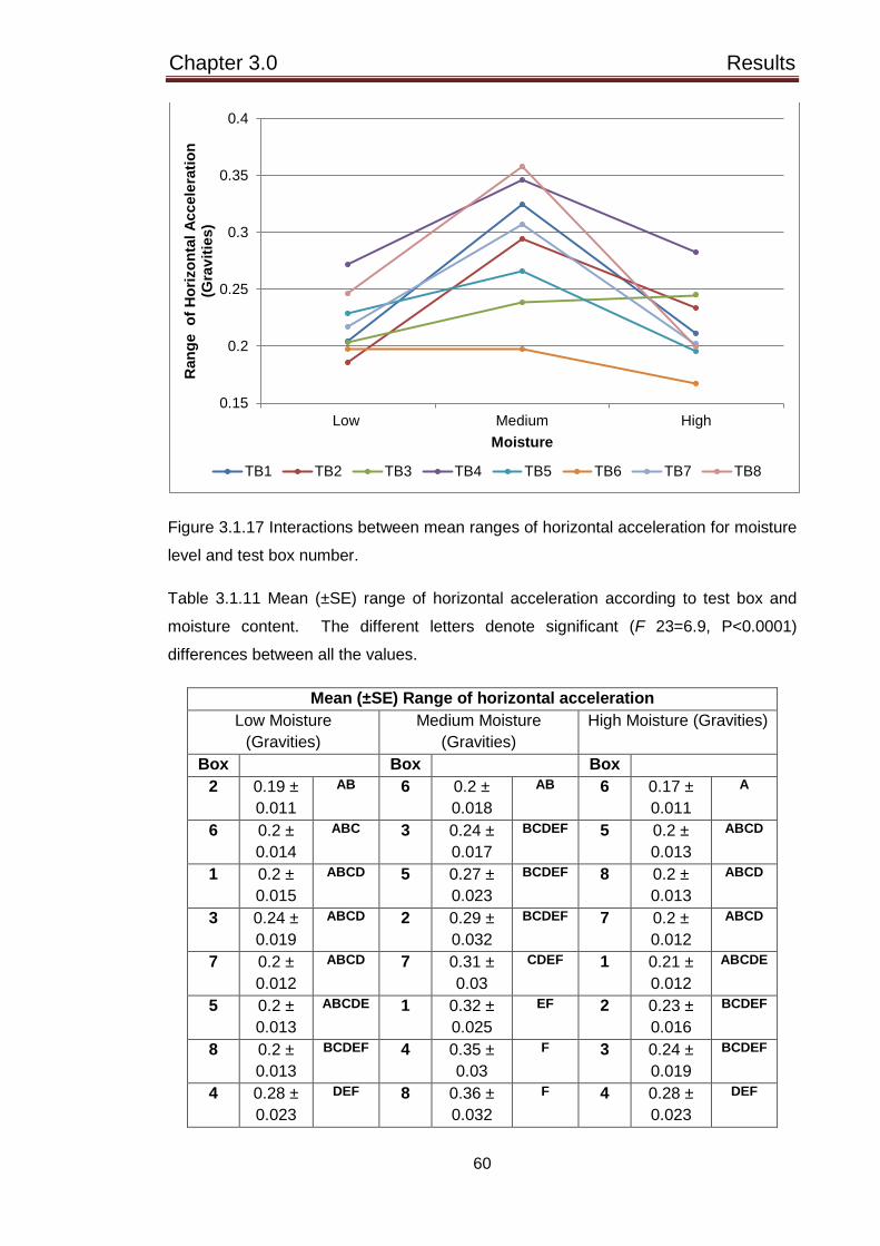
Chapter 3.0 Results
60
Figure 3.1.17 Interactions between mean ranges of horizontal acceleration for moisture
level and test box number.
Table 3.1.11 Mean (±SE) range of horizontal acceleration according to test box and
moisture content. The different letters denote significant (F 23=6.9, P<0.0001)
differences between all the values.
Mean (±SE) Range of horizontal acceleration Low Moisture
(Gravities) Medium Moisture
(Gravities) High Moisture (Gravities)
Box Box Box 2 0.19 ±
0.011 AB 6 0.2 ±
0.018 AB 6 0.17 ±
0.011 A
6 0.2 ± 0.014
ABC 3 0.24 ± 0.017
BCDEF 5 0.2 ± 0.013
ABCD
1 0.2 ± 0.015
ABCD 5 0.27 ± 0.023
BCDEF 8 0.2 ± 0.013
ABCD
3 0.24 ± 0.019
ABCD 2 0.29 ± 0.032
BCDEF 7 0.2 ± 0.012
ABCD
7 0.2 ± 0.012
ABCD 7 0.31 ± 0.03
CDEF 1 0.21 ± 0.012
ABCDE
5 0.2 ± 0.013
ABCDE 1 0.32 ± 0.025
EF 2 0.23 ± 0.016
BCDEF
8 0.2 ± 0.013
BCDEF 4 0.35 ± 0.03
F 3 0.24 ± 0.019
BCDEF
4 0.28 ± 0.023
DEF 8 0.36 ± 0.032
F 4 0.28 ± 0.023
DEF
0.15
0.2
0.25
0.3
0.35
0.4
Low Medium High
Ran
ge o
f Hor
izon
tal A
ccel
erat
ion
(Gra
vitie
s)
Moisture
TB1 TB2 TB3 TB4 TB5 TB6 TB7 TB8

Chapter 3.0 Results
61
Figure 3.1.18 The horizontal acceleration range obtained from each of the test boxes
for all of the treatments.
3.1.7 Maximum vertical deceleration
The maximum vertical deceleration was significantly (F 2=31.77, P<0.0001)
higher on the surfaces with a low and medium moisture level than the surfaces under a
high moisture level. The maximum vertical deceleration significantly (F 2=216.38,
P<0.0001) increased with an increase in surface density, which was the same trend as
the maximum load and load rate values. The surfaces laid on gravel (test boxes 1-4)
generated significantly (F 1=26.95, P<0.0001) higher maximum vertical decelerations
than the surfaces installed on permavoid (test boxes 5-8).
The maximum vertical deceleration was considered when the moisture contents
and bulk densities were combined (Figure 3.1.19). Significant (F 8=41.70, P<0.0001)
differences were found between the different treatments where the high bulk densities
caused a higher vertical deceleration on drop 2 and 3 regardless of moisture content.
The lowest values were recorded on the first drop of the Biomechanical Hoof Tester
when the surfaces had a low density, especially when the surfaces had a high moisture
content. The maximum vertical deceleration recorded on drop number 2 and 3 was
significantly (F 2=219.69, P<0.0001) higher than drop 1 which is the same finding with
the range of horizontal acceleration values.
0
0.1
0.2
0.3
0.4
0.5
0.6
0.7
0.8
0.9
low med high low med high low med high
low medium high
Hor
izon
tal A
ccel
erat
ion
rang
e (G
ravi
ties)
Density
Moisture TB 1 TB 2 TB 3 TB 4 TB 5 TB 6 TB 7 TB8

Chapter 3.0 Results
62
Figure 3.1.19 The mean (± SE) maximum vertical deceleration for the different drop
numbers according to moisture content and bulk density. Different letters (A, B, C, D,
E, F) denote significant (P<0.0001) differences between the combined treatments.
Different letters (a, b) denote significant (P<0.0001) differences between drop
numbers. The significant differences relate to log transformed data.
A significant interaction was found between the maximum vertical deceleration
for the different moisture levels (F 2=9.33, P<0.0001) and the two drainage types at the
high moisture level (Figure 3.1.20). There was no significant (F 2=1.17, P=0.312)
interaction between surface density and drainage type. The maximum vertical
deceleration range for all of the drops combined according to the different treatments is
presented in figure 3.1.21.
a a b
DE
BC
AB
E
BC
A
F
CD
AB
0.3
0.4
0.5
0.6
0.7
0.8
0.9
low med high low med high low med high
low medium high
Max
imum
ver
tical
de
cele
ratio
n (G
ravi
ties)
Density
Moisture Drop 1 Drop 2 Drop 3

Chapter 3.0 Results
63
Figure 3.1.20 Interactions between mean (±SE) maximum vertical deceleration for
moisture level and drainage type (Gravel =TB1-4, Permavoid =TB5-8). Different letters
denote significant (F 5=22.22, P<0.0001) differences between the different moisture
levels applied and drainage type. Letters underlined are shared with other test boxes.
Figure 3.1.21 The range in maximum vertical deceleration values obtained from each
of the test boxes for all of the treatments.
A
A
BC C
BC B
0.52
0.54
0.56
0.58
0.6
0.62
0.64
0.66
Low Medium High
Max
imum
Ver
tical
Dec
eler
atio
n (G
ravi
ties)
Moisture Gravel Permavoid
0
0.1
0.2
0.3
0.4
0.5
0.6
low med high low med high low med high
low medium high
Vert
ical
dec
eler
atio
n ra
nge
(Gra
vitie
s)
Density
Moisture TB 1 TB 2 TB 3 TB 4 TB 5 TB 6 TB 7 TB8

Chapter 3.0 Results
64
The correlation between the vertical deceleration and the surface hardness
readings obtained with the Clegg Hammer was also studied. All of the drops were
considered for the vertical deceleration and drop 2, 3 and 4 were considered for the
Clegg Hammer readings to equalise column lengths and also because the first drop of
the Clegg Hammer tested the immediate top layer. The values were then compared
according to moisture content and bulk density where a significant (P<0.0001) positive
correlation was found for all the treatments. The R value was higher for the high
surface densities regardless of moisture content. The low moisture and high density
combination showed the most significant (F1=108.72, P<0.0001) correlation, which
was also when the surfaces were found to be the hardest (Figure 3.1.22).
Figure 3.1.22 Correlation between surface hardness recorded with the Clegg Hammer
(drop 2, 3, 4) and maximum vertical deceleration recorded with the Biomechanical Hoof
Tester (drop 1, 2, 3) for the low moisture and high surface density.
3.1.8 Shear Modulus
The shear modulus data were non-normal and a Kruskal-Wallis test was used
to determine any significant differences. There were significant (H 2=26.84, P<0.0001)
differences between the different moisture levels where the shear modulus was lower
when the surfaces had a low moisture content (Figure 3.1.23). There were also
significant (H 2=31.76, P<0.0001) differences between the different bulk densities
where the shear modulus reduced with increasing density (Figure 3.1.23). There were
no significant (H 2=2.27, P=0.322) differences between the shear modulus values for
the different drop numbers (Figure 3.1.23). The shear modulus range for all of the
drops combined according to the different treatments is presented in figure 3.1.24.
40
50
60
70
80
90
100
0.3 0.4 0.5 0.6 0.7 0.8 0.9 1 1.1 1.2
Surf
ace
hard
ness
Maximum vertical deceleration

Chapter 3.0 Results
65
Figure 3.1.23 The median shear modulus of the surfaces for the different drop numbers
according to moisture content and surface density.
Figure 3.1.24 The range in shear modulus values obtained from each of the test boxes
for all of the treatments.
00.050.1
0.150.2
0.250.3
0.350.4
0.450.5
low med high low med high low med high
low medium high
Shea
r Mod
ulus
(Rad
ians
)
Density
Moisture Drop 1 Drop 2 Drop 3
0.1
0.2
0.3
0.4
0.5
0.6
0.7
0.8
0.9
low med high low med high low med high
low medium high
Shea
r Mod
ulus
ra
nge
(Rad
ians
)
Density
Moisture TB 1 TB 2 TB 3 TB 4 TB 5 TB 6 TB 7 TB8

Chapter 3.0 Results
66
3.1.8 Hysteresis
The hysteresis relates to the area under the load-displacement curve and
reflects the energy lost on impact with the surface. The higher values were associated
with higher forces and a smaller displacement, which represent a greater amount of
energy lost on impact. The lower values were associated with lower forces and a
higher displacement and represent a lower amount of energy lost on impact. The
moisture level significantly (F 2=18.19, P<0.0001) affected the hysteresis where the
low moisture content significantly (P<0.0001) increased the energy loss on impact in
comparison to the medium and high moisture level. Surface density significantly (F
2=83.46, P<0.0001) altered the hysteresis where the low and medium densities
significantly (P<0.0001) reduced energy loss when compared to the high density.
The hysteresis was considered when the moisture contents and bulk densities
were combined (Figure 3.1.25). Significant (F 8=26.43, P<0.0001) differences were
found between the different treatments where the surfaces with a high density and low
moisture content generated the highest energy lost on impact (Figure 3.1.25). The
lowest energy loss was created when the surfaces had a low or medium density with a
medium or high moisture level. The energy loss on impact was significantly (F
2=70.53, P<0.0001) lower on drop one than drop two and three, which was the same
finding with the maximum vertical deceleration and range of horizontal acceleration.

Chapter 3.0 Results
67
Figure 3.1.25 The mean (± SE) hysteresis for the different drop numbers according to
moisture content and bulk density. Different letters (A, B, C, D, E) denote significant
(P<0.0001) differences between the combined treatments. Different letters (a, b)
denote significant (P<0.0001) differences between drop numbers.
Significant interactions were found between the hysteresis for the different
moisture levels (F 14=7.02, P<0.0001) and test box number (Figure 3.1.26). Table
3.1.12 presents the mean (±SE) hysteresis according to moisture content and where
the significant differences lie between the test boxes. Significant interactions were also
found between the hysteresis for the different surface densities (F 14=11.16,
P<0.0001) and test box number (Figure 3.1.27). Table 3.1.13 presents the mean (±SE)
hysteresis according to bulk density and where the significant differences lie between
the test boxes. It is important to note that the values recorded according to moisture
content and bulk density are split according to the drainage type (TB 1-4: gravel, TB 5-
8: permavoid) the surface is laid upon where the energy lost on impact was higher on
gravel. The hysteresis recorded for the different surface densities (Figure 3.1.27) in the
test boxes laid on permavoid (TB 5-8) appeared to be more consistent and suggests
that drainage type rather than surface type was a greater influence on the results. The
hysteresis range for all of the drops combined according to the different treatments is
presented in figure 3.1.28. The surfaces with the highest hysteresis readings
generally had the largest range.
b a a
CD DE
A
E E
B
DE DE
BC
160
170
180
190
200
210
220
low med high low med high low med high
low medium high
Hys
tere
sis
(Jou
les)
Density
Moisture
Drop 1 Drop 2 Drop 3

Chapter 3.0 Results
68
Figure 3.1.26 Interactions between mean hysteresis for moisture level and test box
number.
Table 3.1.12 Mean (±SE) hysteresis according to test box and moisture content. The
different letters denote significant (F 23=30.50, P<0.0001) differences between all the
values.
Mean (±SE) Hysteresis Low Moisture
(Joules) Medium Moisture
(Joules) High Moisture
(Joules) Box Box Box
4 212 ± 4.44
A 1 203.6 ± 3.26
ABC 4 201.2 ± 4.22
BC
3 206.2 ± 3.29
AB 4 197.3 ± 3.4
BCD 3 200.1 ± 2.34
BC
1 203.9 ± 2.85
ABC 2 195.3 ± 2.88
CD 1 194.5 ± 1.96
CD
2 200.2 ± 3.29
BC 3 187.6 ± 2.37
DEF 2 188.8 ± 2.28
DE
8 188.9 ± 1.08
DE 6 182.3 ± 1.24
EFG 6 183.4 ± 1.18
EFG
7 182.6 ± 0.9
EFG 5 180.4 ± 1.57
EFG 5 180.8 ± 1.64
EFG
6 178.5 ± 1.19
EFG 8 177.1 ± 1.45
FG 7 179.5 ± 1.66
EFG
5 173.5 ± 1.74
G 7 174.7 ± 1.9
G 8 176.2 ± 1.7
G
170
175
180
185
190
195
200
205
210
215
Low Medium High
Hys
tere
sis
(Jou
les)
Moisture
TB1 TB2 TB3 TB4 TB5 TB6 TB7 TB8

Chapter 3.0 Results
69
Figure 3.1.27 Interactions between mean hysteresis for the different bulk densities and
test box number.
Table 3.1.13 Mean (±SE) hysteresis according to test box and bulk density (BD). The
different letters denote significant (F 23=41.12, P<0.0001) differences between all the
values.
Mean (±SE) Hysteresis Low BD (Joules)
Medium BD (Joules)
High BD (Joules)
Box Box Box 1 193.5 ±
2.03 DEF 1 198.8 ±
2.31 CD 4 226 ±
4.15 A
3 192.8 ± 1.83
DEF 4 193.6 ± 3.09
DE 1 209.6 ± 3.25
B
4 191.9 ± 2.17
DEFG 3 192.1 ± 2.75
DEF 2 209.8 ± 3.04
B
2 187.8 ± 2.08
EFGH 2 187.3 ± 1.86
EFGH 3 208.7 ± 3.32
BC
8 181.4 ± 1.76
HI 6 179.1 ± 1.5
HI 6 184.5 ± 0.91
EFGHI
6 180.5 ± 1.09
HI 8 179.1 ± 1.4
HI 5 182.9 ± 1.46
FGHI
7 179.5 ± 1.57
HI 7 178.9 ± 1.26
HI 8 181.7 ± 1.97
GHI
5 176.3 ± 1.59
I 5 175.6 ± 1.89
I 7 178.5 ± 1.98
HI
170
180
190
200
210
220
230
Low Medium High
Hys
tere
sis
(Jou
les)
Bulk Density
TB1 TB2 TB3 TB4 TB5 TB6 TB7 TB8

Chapter 3.0 Results
70
Figure 3.1.28 The range in hysteresis values obtained from each of the test boxes for
all of the treatments.
The load-displacement curves for test box 1 (Sand and medium fibre and wax
on gravel) and 5 (Sand and medium fibre and wax on permavoid) are shown in Figure
3.1.29. The readings were taken on the first drop of the Biomechanical Hoof Tester for
the three surface densities and the three graphs demonstrate the effects of the different
moisture contents (A, B, C). The curves appear to alter according to drainage type
where the sand and medium fibre and wax surface on permavoid was associated with
higher deformations and lower forces, creating a smaller area under the curve and
therefore a lower amount of energy lost on impact. The same surface on gravel was
associated with a larger area under the curve and demonstrates that a higher energy
loss would occur on impact.
0
10
20
30
40
50
60
70
80
90
low med high low med high low med high
low medium high
Hys
tere
sis
rang
e (J
oule
s)
Density
Moisture TB 1 TB 2 TB 3 TB 4 TB 5 TB 6 TB 7 TB8

Chapter 3.0 Results
71
Figure 3.1.29 Load-displacement curves for TB1 and TB5 according to moisture
content and bulk density recorded during the first drop of the Biomechanical Hoof
Tester.
0100020003000400050006000700080009000
1000011000
0 0.01 0.02 0.03 0.04 0.05 0.06
Forc
e (N
)
Displacement (m)
0100020003000400050006000700080009000
1000011000
0 0.01 0.02 0.03 0.04 0.05 0.06
Forc
e (N
)
Displacement (m)
0100020003000400050006000700080009000
1000011000
0 0.01 0.02 0.03 0.04 0.05 0.06
Forc
e (N
)
Displacement (cm)
TB1 Low TB1 Medium TB1 High
TB5 Low TB5 Medium TB5 HighBulk Density

Chapter 3.0 Results
72
3.1.9 Summary of results
The main findings from the field based study according to treatment effects on
the measured parameters are presented in table 3.1.14.
Table 3.1.14 Summary of the main findings for how the parameters were affected by
the moisture contents and surface densities.
Parameter assessed
Main findings Significance level
Torque Wrench Traction p. 45
-Increased with increasing moisture level. -The surface density did not significantly affect traction.
P<0.0001 P=0.684
Clegg Hammer Hardness p. 47
Drop 1: -The moisture level did not significantly affect surface hardness. -Medium and high bulk densities made the surface significantly harder in comparison to the surfaces with a low density. Drop 4: -The surfaces with a low moisture content were significantly harder than the surfaces under a medium and high moisture level. -The surfaces significantly increased in hardness with increasing bulk density. Range from drop 1-4: -Significantly greater for a low moisture level than medium and high moisture levels. -A greater range was recorded whilst the surfaces had a high density.
P=0.188 P<0.0001 P<0.0001 P<0.0001 P<0.0001 P<0.0001
Biomechanical Hoof Tester Maximum load p. 51
-A high and medium moisture level created significantly (P<0.0001) higher load values than the low moisture level. - The maximum load significantly increased with each increase in bulk density.
P<0.0001 P<0.0001
Load rate p. 55
-A medium moisture level generated a significantly higher load rate than the high moisture level which was significantly higher than the low moisture content. -The load rate significantly increased with each increase in bulk density.
P<0.0001 P<0.0001
Range of horizontal acceleration
-Significantly higher when the surfaces were under a medium moisture level than under a low and high moisture level.
P<0.0001

Chapter 3.0 Results
73
p. 58 -Significantly lower when the surfaces had a low density.
P=0.036
Maximum vertical deceleration p. 61
-Significantly higher on the surfaces with a low and medium moisture level than with a high moisture level. -Significantly increased with an increase in each bulk density.
P<0.0001 P<0.0001
Shear modulus (Kruskal-Wallis) p. 64
-Significantly lower when the surfaces had a low moisture level. -Shear modulus reduced with increasing bulk density.
P<0.0001 P<0.0001
Hysteresis p.66
-The low moisture level created significantly higher values than the medium and high moisture levels. -Low and medium surface densities generated significantly lower values than a high density.
P<0.0001 P<0.0001

Chapter 3.0 Results
74
3.2 Questionnaire based study
The responses (n=342) from the rider preference survey were split initially
according to the discipline of the riders (Figure 3.2.1). Dressage is a discipline where
the horse is ridden through a series of movements in order to test the obedience,
suppleness and balance of the horse. Show jumping involves the horse being jumped
over a series of fences or obstacles. Eventing has three phases which includes
Dressage, Show jumping and a Cross Country phase where the horse must work over
varying terrain and obstacles and requires stamina and confidence. The ‘other’
disciplines that have been specified in the survey included showing where the
conformation and movement of the horse are assessed, endurance and general leisure
riding. Not all of the answers were completed by some of the participants, possibly
because they did not feel a question was relevant to them. For example a rider who
does not compete may not have completed a question regarding competition surfaces.
The responses for all the other questions that the particular respondents completed
were considered.
Figure 3.2.1 Proportion of riders from the different disciplines responding to the survey.
The riders were also categorised according to the level that their horse was
competing at. The technical moves required at higher levels can be expected to have
a greater degree of difficulty where a horse completing a canter pirouette or a course of
1.20 metre fences at professional level will be affected by the surface type more than a
novice horse completing more basic movements. It is therefore assumed that riders
39.22%
28.13%
20.94%
11.70%
DressageShow JumpingEventingOther

Chapter 3.0 Results
75
competing at a higher level will be more aware on how a horse interacts with the
surface (Murray et al., 2010a). Table 3.2.1 shows how the different levels were
determined. The proportion of riders at the different levels is a good reflection of the
actual population where fewer riders make it to the higher levels. It is important to note
that not all of the respondents provided information on the current level of competition
of the horse however their responses were still included under a ‘no level stated’
category.
Table 3.2.1 Different level of riders and how they were categorised according to
competition level.
Level Competition level
1 (Novice) (n=52) British Dressage – Intro and Prelim
Unaffiliated Show Jumping, Eventing and Showing
2 (Intermediate) (n=90) British Dressage - Novice and Elementary
British Show Jumping - British Novice (90cm)
British Eventing (BE) – BE80, BE90
3 (Advanced) (n=44) British Dressage – Medium
British Show Jumping – Discovery (1.00m) and Newcomers
(1.10m)
British Eventing (BE) – BE100 and Pre-novice
County level Showing
4 (Professional) (n=21) British Dressage – Advanced Medium – Grand Prix
British Show Jumping – Foxhunter (1.20m)
British Eventing (BE) – Novice and Intermediate, CCI 1* FEI
2**

Chapter 3.0 Results
76
0
10
20
30
40
50
60
A large amount(almost no slip)
Moderate (smallamount of slip)
A small amount (alarger amount of
slip)
No preference
Num
ber o
f res
pons
es
Preferred amount of traction Level 1 Level 2 Level 3 Level 4 No level stated
3.2.1 Preferred amount of Traction
A question was constructed for the rider preference survey to establish the
amount of traction that riders prefer. The discipline of the rider did not significantly (F
3=2.64, P=0.113) affect the choice of preferred amount of traction. A moderate and
large amount of traction was the most popular choice, however there was no significant
(X2 8=0.7095, P>0.05) association between the level of rider and the preferred amount
of traction selected (Figure 3.2.2). All of the riders who preferred a small amount of
traction (n=3) also preferred a softer ‘way of going’.
Figure 3.2.2 The number of responses relating to the preferred amount of traction a
surface provides.
3.2.2 Preferred way of going
A question was constructed for the rider preference survey to establish the ‘way
of going’ that riders prefer which relates to surface hardness that was measured in the
test boxes during the field based study. The discipline of the rider did not have a
significant (F 3=2.58, P=0.092) effect on the choice of preferred ‘way of going’. The
most popular preferences included ‘firm with a bit of give’ and ‘a softer surface with a
bit more give’ however there was no significant (X2 8=14.217, P>0.05) association
between the answers selected and the different levels of rider (Figure 3.2.3). It is still
important to note that more level 1 riders preferred a softer surface with a bit more give
than a surface that is firm and offers a bit of give. The technical movements required of
a level one horse and rider combination are expected to be easier than the other levels,

Chapter 3.0 Results
77
suggesting that the way in which a softer surface affects performance is not yet
apparent.
Figure 3.2.3 The number of responses relating to the preferred way of going a surface
provides.
The participant that selected ‘deep’ (n=1) as a preferred way of going
participates in Dressage and Eventing and appeared to train and compete on a wide
variety of surfaces. The level one participant that selected ‘other’ (n=2) for their
preferred way of going participates in Show Jumping and specified that they want the
surface to ‘bounce’ with no give however they did not specify a preferred surface type
to ride on. The other respondent selecting ‘other’ was considered to be a level 2 rider
who trains and competes in Dressage and Show Jumping on a variety of surfaces and
stated they prefer a firm surface that allows ‘some longitudinal slip’ and ‘good going on
grass is the best’.
0
10
20
30
40
50
60
Hard withno give
Firm with abit of give
A softersurface witha bit more
give
Deep Other Nopreference
Num
ber o
f res
pons
es
Preferred way of going
Level 1 Level 2 Level 3 Level 4 No level stated

Chapter 3.0 Results
78
3.2.3 Training, competition and preferred surfaces
A question was constructed for the rider preference survey to establish the
surface types used for training and competition and also the preferred surface type to
ride on (Figure 3.2.4).
Figure 3.2.4 Training, competition and preferred surface types of the riders who
responded to the survey.
There was a significant (X2 22=157.754, P<0.0001) association between the
surface type according to training, competition and preferred surface (Table 3.2.2).
020406080
100120140
Num
ber o
f res
pons
es
Surface type
Training Competiton Preferred

Chapter 3.0 Results
79
Table 3.2.2 Chi-square test (X2 22=157.754, P<0.0001) for the training, competition
and preferred surface types. Observed and expected values and chi-square contributions are presented.
Surface Training Competition Preferred Total Sand and Fibre
with wax 37
84.84 26.976
124 113.61 0.950
132 94.55
14.832
293
Sand and Fibre non wax
52 57.62 0.548
82 77.16 0.304
65 64.22 0.010
199
Sand and PvC with wax
9 22.87 8.416
33 30.63 0.183
37 25.49 5.194
79
Sand and PvC non wax
17 18.53 0.127
36 24.82 5.041
11 20.65 4.512
64
Rubber based (mixed in)
79 65.15 2.944
76 87.24 1.449
70 72.61 0.094
225
Rubber based (on top)
61 53.57 1.031
69 71.73 0.104
55 59.70 0.370
185
Carpet fibre
24 26.06 0.163
34 34.90 0.023
32 29.04 0.301
90
Just sand
44 28.09 9.016
28 37.61 2.456
25 31.30 1.269
97
Wood chip
32 14.77
20.109
8 19.77 7.011
11 16.46 1.810
51
Grass
94 80.21 2.372
122 107.40 1.983
61 89.39 9.016
277
Other
14 8.11 4.283
8 10.86 0.752
6 9.04 1.020
28
No preference 0 3.19 3.185
0 4.27 4.265
11 3.55
15.637
11
Total 463 620 516 1599 The expected values for the non-waxed sand and fibre and carpet fibre surface
were very similar to the observed values. The expected values for a waxed sand and
fibre surface were higher for a training surface and lower for the competition and
preferred surface which was a similar finding with the waxed sand and Polyvinyl
chloride (PvC) granules surface. The non-waxed sand and PvC surface is used more
often than expected for competition and a lower number of respondents preferred the
surface than expected. The rubber based surfaces, just sand and woodchip are used
for training more often than expected and the observed values for competition and
preferred surface type are lower than expected. There was a similar finding with grass

Chapter 3.0 Results
80
however it was expected that grass was used less for competition than the
observations made. It is important to note however that the grass surface is the only
natural occurring surface that riders could choose from and the remaining surface
types were all synthetic. The higher response rate seen for some of the training
surfaces may be affected by other factors such as finances available to construct the
arena or other facilities available that encourage a particular client to use a yard.
The responses for ‘other’ surface types were looked at in more detail where
some of the respondents stated they prefer to ride on surfaces manufactured by
specific companies. Sand and flexiride which is carpet and foam laid on top of sand
was also a preferred surface and one respondent stated that any surface that is not too
deep or hard would be ideal. The ‘other’ types of training and competition surfaces
included sand mixed with carpet fibre, cushion ride which is made from wood fibre,
Martin Collins clopft pre-mixed surface, ash and flexi ride. The respondents that did
not have a preferred surface type were predominantly riding at a level one standard
according to the categories in table 3.2.1 (p.75).
There may be other factors that affect the preferred amount of traction, ‘way of
going’ and surface type such as the training surfaces used and the way in which it may
aid or hinder the performance of the horse. Figure 3.2.5 shows the number of riders
who train indoors or outdoors and in which conditions the surface provides them with
an optimal performance on their horse.
Figure 3.2.5 The number of riders who train indoors (n=30) or outdoors (n=200) and in
which conditions the surface provides them with an optimal performance on their horse.
0102030405060708090
All the timeregardlessof weather
During aperiod of
dry weather
During aperiod of
dry and wetweather
During aperiod of
wet weather
After beingthoroughlywatered
Other
Num
ber o
f res
pons
es
Conditions in which the training surface provides the best performance
Indoor Outdoor

Chapter 3.0 Results
81
There was a significant (X2 4=27.606, P<0.0001) association between the
conditions in which an arena provides the best performance and whether the arena is
indoor or outdoor (Table 3.2.3).
Table 3.2.3 Chi-square test (X2 4=27.606, P<0.0001) for the conditions in which the
indoor or outdoor training surface provides the best performance. Observed and
expected values and chi-square contributions are presented.
Condition Indoor Outdoor Total All the time
regardless of weather
21 10.36
10.936
59 69.64 1.626
80
During a period of dry weather
1 3.24 1.546
24 21.76 0.230
25
During a period of dry and wet
weather
4 11
4.458
81 74
0.663
85
During a period of wet weather
0 3.37 3.366
26 22.63 0.501
26
After being thoroughly watered
3 1.04 3.725
5 6.96 0.554
8
Total 29 195 224
The expected values for indoor arenas providing the best performance all the
time regardless of weather conditions and also when the arena had been thoroughly
watered were lower than observed and were higher than observed for the outdoor
arena. Expected values for the indoor arenas performing the best in a period of dry
weather, in a period of dry and wet weather and in a period of wet weather were all
higher than the observed values whereas the outdoor arenas exposed to the same
conditions had higher values than expected. Environmental conditions are more easily
controlled within an indoor arena in comparison to outdoor arenas however it can also
pose a problem if the arena is not managed correctly and the moisture content
fluctuates.
The respondents selected ‘other’ as an option for various reasons including
arenas being affected by extremes in weather conditions such as snow or torrential rain
and irregular maintenance but provide an optimal performance for their horse in all
other conditions. A respondent stated their arena performed best when it was as wet
as possible without standing water and another participant prefers their arena when it
has been harrowed followed by rainfall.

Chapter 3.0 Results
82
3.2.4 Summary of Results
The main findings from the questionnaire based study according to rider preferences
regarding surface type and properties are presented in table 3.2.4.
Table 3.2.4 Summary of questionnaire results.
Factor Most popular selection
Traction Moderate
Way of going Firm with a bit of give
Surface type (training) Grass (higher than expected)
Surface type (Competition) Waxed sand and fibre surface (higher than
expected)
Surface type (Preferred) Waxed sand and fibre surface (higher than
expected)
Conditions in which the surface performs best (indoor)
All the time regardless of weather
Conditions in which the surface performs best (outdoor)
During a period of dry and wet weather

Chapter 4.0 Discussion
83
4.0 DISCUSSION
The aims of the current study were to measure the effect of moisture, density
and drainage on different equine sand and fibre arena surfaces and to establish the
preferences of riders regarding surface properties. The alternative hypotheses were
supported where a significant change in surface properties under different testing
conditions and differences in the preferences of riders were found. The three different
moisture contents and three surface densities caused significant alterations in the
traction, hardness and measurements recorded with the Biomechanical Hoof Tester.
There are indications that drainage layer and surface type also affected the readings
obtained.
4.1 Traction
The different moisture contents significantly affected traction where traction
increased with an increase in moisture level. There appeared to be a larger difference
in the surface traction between the low and medium moisture contents than between
the medium and high moisture contents, possibly because there was a larger
difference between the actual moisture contents recorded for the low and medium
moisture levels. Surface one (sand and medium fibre and wax) on permavoid (test box
5) showed the greatest rise in traction when the surfaces had a high moisture content.
At lower moisture contents, the sand particles move easily against each other,
possibly resulting in the surface giving way more readily against the force of the Torque
Wrench and implies why lower traction was recorded at lower moisture contents
(Murray et al., 2010a). Higher moisture contents increase the particle adherence and
stability of the surface and that would explain why traction rose as moisture content
increased in this study (Murray et al., 2010a). The optimum water content for sand has
been suggested to be between 8% and 17% where alterations in this have affected
other properties such as the hardness and energy lost to the surface at hoof impact
(Barrey et al., 1991; Ratzlaff et al., 1997).
Alterations in water content in this study have also demonstrated that it is
possible to change the traction of a surface. Surface four (sand and low fibre and low
wax) laid on the gravel (TB 4) had consistently higher traction values, which could be
explained by a higher moisture content being measured on this combination throughout
the study. The particle size of the surface will also affect the moisture retention of the
surface where smaller particles have previously shown to hold more moisture (Baker
and Firth, 2002). The particle size analysis performed during this study revealed that
surface four and the sand and high fibre, no wax surface (surface 2) had a smaller

Chapter 4.0 Discussion
84
particle size and could explain why surface four held a higher moisture content.
Surface two was un-waxed, which will have affected the cohesive properties and may
explain why higher moisture contents and traction values were not recorded on this
substrate.
The surface density and sub base type did not have a significant effect on the
traction. The higher degree of compaction reduced the pore spaces between the sand
particles, reflected by a higher bulk density and traction values may have been
expected to rise due to less movement between particles occurring. A medium and
high compaction of a non-turfed basepath has yielded greater traction values in
comparison to a low degree of compaction (Brosnan et al., 2009). Moisture contents
were measured but not controlled in the study by Brosnan et al. (2009). It was evident
that moisture had a larger effect than bulk density during this study.
The traction of sand based greyhound tracks increased with increasing
moisture content and density in a study by Baker and Firth (2002). The traction
apparatus used was adapted to represent the dimensions of an average greyhound
footprint and weighed 30kg, which is the same as the current study and could explain
some of the similarities between the results. The effects of the base layer, which
included gravel or sandy loam soil on traction were small and suggests that the top
layer of the surface has the greatest impact on traction (Baker and Firth, 2002).
Traction has also shown a strong positive response to increasing the rate of
Alginure, applied to a sand based football surface in a study by Canaway (1992).
Alginure is a water retentive product and its addition increased traction values from
28Nm to 39Nm when the sports surface was being supplied with 25mm of water every
week. An increase in moisture, also increased static friction of skinned infields used
for baseball and softball in a study by Goodall et al. (2005) however, there were no
clear trends between moisture content of different soils and traction values. The static
friction and traction was measured using a similar apparatus to Canaway and Bell
(1986) however it was modified with two plates that held four baseballs and steel
baseball cleats respectively. The moisture contents used for the study included 10%,
14% and 18% and the bulk density of the different soils ranged from 1.57-1.70 Mg m-3
(Goodall et al., 2005). The different soils tested included silt loam, loam, coarse sandy
loam, loamy sand and loamy coarse sand, which had larger particle sizes than the
surfaces used for this study. The traction values of 22.8-29.2Nm were also
comparable to the higher values recorded during the current study and so the different
particle sizes and apparatus used could be a relevant explanation for the variation in
the trends between moisture and traction.

Chapter 4.0 Discussion
85
The traction of natural turf football pitches did not appear to alter according to
moisture content, which varied from approximately 8% to 50% in a study by Baker
(1991). The traction was measured using a 45 kg studded disc apparatus (Canaway
and Bell, 1986) and varied from approximately 14 Nm to 51 Nm, which were
considerably higher than the readings taken during this study. The heavier weight of
the traction apparatus and the presence of sward will have been critical in raising the
values. The traction was more dependent on the amount of ground cover than
moisture content and Goodall et al. (2005) stated that plant root systems increase
tensile strength and therefore surface traction.
Adding fibres to supplement the strength and quality of sand rootzones
improved stability and traction when compared with unreinforced sand (Baker and
Richards, 1995). The mean gravimetric moisture content varied from 3.2% to 15.9%
however there was no clear relationship between traction and moisture content (Baker
and Richards, 1995). A similar finding was obtained by Spring and Baker (2006) where
turf strength increased with more polypropylene fibres, which was reflected by higher
traction values however, no relationship again was identified between moisture (20.8-
31.1%) and traction (41.4-64.7Nm). Surface type and composition appears to have a
larger impact on the traction values recorded in studies on human sports surfaces in
comparison to moisture content. There is no other published literature on the traction
of equine arena surfaces measured using similar apparatus to this study, making
comparisons between studies a challenge at present.
Moisture content, surface type and the weight and style of the traction
apparatus have affected the values obtained in the different studies. The reliability
between testers measuring traction was also a significant factor affecting the readings
in a study by Twomey et al. (2011) where values ranged from 15.2Nm to 21.1Nm
between users regardless of experience on the same area. The low reliability identified
by Twomey et al. (2011) was also attributed to a lack of control and quantification of the
speed in which the device is rotated and may have differed between the studies. The
range may appear small however it was sufficient to cause significant differences
between treatments in this study. The large variability could greatly alter the
significance of recorded values and consequently the same tester was used to
measure traction throughout this study.
Most of the riders who responded to the survey preferred a surface that offered
a ‘moderate amount of traction (small amount of slip)’ and there was also a notable
sample who preferred a ‘large amount of traction (almost no slip)’. The choice of the
rider may have been affected by a recent competition where the horse performed well.

Chapter 4.0 Discussion
86
An insecure footing, offering little grip will negatively influence performance and affect
the confidence of horse and rider, which explains why very few riders (n=3) selected a
low amount of traction. A surface with too much traction conversely, will pose a serious
risk to the horse in terms of injury (Gustås et al., 2006a).
It is not possible to quantify the exact degree of slip that riders prefer from the
results of this study however, it provides baseline information that can be considered in
the future during arena construction and management. If a rider wishes to increase the
grip or traction of a surface, they should initially consider increasing the moisture
content or maintaining an optimum moisture content for that surface. It is important to
note that there was a maximum mean moisture content of 21.19% and further studies
must be carried out to establish the moisture content that generates the highest traction
values before particle adherence is exceeded and begin to separate when saturated.
The recommendation can only be made for waxed and unwaxed sand and fibre
surfaces at present and future work on different equine arena surfaces would be
valuable.
4.2 Hardness
Surface hardness was assessed by the first drop, fourth drop readings and
difference between the respective drops of a 2.25 kg Clegg Hammer and were studied
more closely. The first drop provided information on the top layer of the surface
whereas the fourth drop values showed changes in the substrate once it had been
compacted slightly with the 2.25 kg Hammer. It is important to consider the drop
number of the Clegg Hammer separately because the treatments had a different effect
according to whether the top layer or more compacted layers were being tested. Drop
one values have shown to be misleading however, they are an important consideration
when subsequent drops are also reported (Setterbo et al., 2011).
The first drop readings were not significantly affected by the different moisture
contents however a medium and high surface density created harder surfaces than the
low density. The bulk density for the medium and high degree of compaction was
similar and possibly supports why there was no change observed in surface hardness
of the top layer between the respective densities. The hardness values increased with
each drop of the Clegg Hammer, which was a similar finding to Setterbo et al. (2011)
who compared a synthetic and dirt race track.
The fourth drop readings were significantly affected by the moisture content
where the surfaces under a low moisture content were significantly harder, which
demonstrates that moisture is a factor affecting hardness below the top layer of the

Chapter 4.0 Discussion
87
surface. The fourth drop also identified an increase in hardness with each compaction
level and suggests that this drop is more sensitive to detecting changes in surface
density. The top layer of a maintained arena surface is generally compacted down
after its first use and therefore the fourth drop readings potentially relate to surfaces
that have been used post maintenance.
The drainage system has been shown to have a significant effect on surface
hardness for all of the Clegg Hammer drops where TB 1-4 on gravel and TB 8 on
permavoid were harder than TB 5-7 on permavoid. Surface four (sand and low fibre
and low wax in TB 4 and 8) generated consistently higher hardness values regardless
of drainage type, which is possibly related to having a higher bulk density compared to
the other surfaces. The smaller particle size of surface four may have also improved
the compactability of the surface and further supports why a higher bulk density was
measured.
The addition of polypropylene and polyurethane fibres to winter games pitches
has been shown to affect the ability of the surface to compact and significantly reduce
hardness values (Spring and Baker, 2006). The sand and low fibre and low wax
surface (surface four) in this study had a lower fibre rate than the other surfaces and
the findings of Spring and Baker (2006) could support why this surface was associated
with significantly higher hardness values. The presence of fibres made winter games
pitches harder in a study by Baker and Richards (1995), which conflicts with this study
and Spring and Baker (2006). The justification of Baker and Richards (1995) was a
higher fibre content increased hydraulic conductivity making the surfaces more freely
draining and low moisture levels more readily achievable. The surfaces that held a
lower moisture content in this study also had a lower overall bulk density suggesting
that a higher bulk density of a surface with a smaller proportion of fibres was more
likely to increase hardness.
The bulk density of all the surfaces laid on gravel was also higher, indicating
more compaction and may explain why higher surface hardness values were recorded
on the sub-base. The maximum force applied to simulate a medium and high degree
of compaction however, was the same for the surfaces laid on gravel and permavoid.
The results suggest that the surfaces on permavoid are less susceptible to compaction
possibly because the units deflect some of the force applied, creating a lower bulk
density. The findings indicate that the drainage type and therefore the way in which the
surfaces were compacted had the largest impact on the hardness readings.

Chapter 4.0 Discussion
88
Sand-based greyhound race surfaces were laid over gravel and soil in a study
by Baker and Firth (2002) and were consistently harder on gravel, suggesting that the
stiffness of the sub-base can alter the surface properties. Moisture content and bulk
density also had a significant effect on the hardness where values increased as the
sand became drier and denser, which supports the results of this study (Baker and
Firth, 2002). The moisture contents measured were higher than this study however,
the hardness readings obtained with a lighter (0.5 kg) Clegg Hammer were
comparable. Hardness values were also very dependent on moisture content
measured on a turf racetrack where the highest hardness values were obtained at
lower moisture contents (Baker et al., 1999). The moisture contents recorded however,
were much higher, varying from 23-51%. It would be interesting to establish whether
hardness continued to reduce at higher moisture contents prior to saturation in future
investigations.
Moisture content was the primary influence on surface hardness of baseball
skinned infields, which are sand based surfaces (Goodall et al., 2005). Hardness
decreased as moisture increased, which was a similar finding to this study at
comparable moisture levels (10%, 14% and 18%). There were fewer differences in
hardness readings according to the amount of compaction at higher moisture contents,
which was attributed to the ability of the soils tested to drain freely (Goodall et al.,
2005). The amount of compaction was altered in a different manner with a vibratory
plate compactor and the bulk density was recorded according to the surface type and
soil particle size and could explain the different findings to this study.
Compaction treatments were applied with a Brinkman traffic simulator to three
different baseball surfaces in a study by Brosnan et al. (2009) including a non-turfed
basepath, natural turfgrass and synthetic turf with varying infill depths. Increasing
levels of soil compaction yielded increases in surface hardness. Synthetic surface type
also influenced the results where no infill generated the highest readings. The
moisture content was not controlled and a quadratic relationship was found between
plots receiving medium and high compaction treatments measuring lower in soil
moisture content than plots receiving the low compaction treatment (Brosnan et al.,
2009). The increasing bulk density may have reduced the air space left for moisture to
occupy and possibly reduced the moisture content, explaining why the hardness
increased. The moisture content in this study did not significantly alter with a change in
surface density, possibly because the surfaces were tested within three hours of water
being applied. The low moisture and high compaction treatment combination however,
did generate the highest hardness readings.

Chapter 4.0 Discussion
89
The riders who responded to the survey prefer a ‘firm surface with a bit of give’,
which could be achieved by reducing the moisture content and increasing the amount
of compaction depending on the original condition of the surface. The difference
between the first and fourth drop was significantly higher during this combination in
comparison to any of the other treatments. The difference between the drops provides
information on the bulk density of the surface with successive drops of the Clegg
Hammer and higher differences could pose a risk for injury because it would not supply
a consistent footing for all horses working over that particular combination (Murray et
al., 2010b). The surfaces laid on permavoid, although associated with softer surfaces,
significantly lowered the range in hardness values and suggests that a surface installed
on a permavoid sub-base would provide a more uniform surface. The different levels
of moisture, bulk density, drainage and surface type have all influenced the surface
hardness in this study. There was a strong interdependence between the variables as
suggested by Goodall et al. (2005), which poses a challenge that must be addressed
when trying to create a consistent surface.
4.3 Maximum Load and Load rate
The maximum load recorded using the Biomechanical Hoof Tester was greater
when the surfaces had a medium and high moisture content. Maximum load for three
test boxes did however reduce from medium to high moisture contents. A study by
Chateau et al. (2010) involved attaching a dynamometric horseshoe to the fore hoof of
four trotter horses that were working on beach sand with varying moisture contents and
depths (Firm wet sand:19%, Deep wet sand: 13.5%, Deep dry sand:3%). The results
indicated that deep dry sand surfaces reduce the impact force in both vertical and
horizontal directions during landing, which is comparable to this study (Chateau et al.,
2010). The observations made by Chateau et al. (2010) and during this study suggest
that the distal limb is subjected to reduced mechanical stress during the initial part of
the stance phase on drier surfaces.
A high correlation between vertical force and moisture content of a dirt race
track was identified by Ratzlaff et al. (1997) where the trend line created an inverted
bell shape with the lowest forces associated with a moderate moisture content (6-10%).
The study involved testing the surface, which was mainly medium to coarse sand with
six horses fitted with piezoelectric transducers and a track testing device at lower
moisture contents (approximately 2%) than this study (6.83%), which could explain the
different findings (Ratzlaff et al., 1997). The results contradict the observations made
by Chateau et al. (2010) at lower moisture contents however, the racing surfaces
tested by Ratzlaff et al. (1997) were harrowed and more compact. Further research

Chapter 4.0 Discussion
90
would be required to observe the maximum load on surfaces with a lower moisture
content. The conditions under which testing took place were also more variable than
for this study, which could have affected the results where humidity and temperature
ranged from 24-91% and 37-94ºF respectively (Ratzlaff et al., 1997).
The horse must experience a relatively high maximum load during the support
phase of the stride in order for the cost of locomotion to be efficient (Figure 1.1 C, p.4).
The maximum load was also considered in terms of body weights where one body
weight approximately equates to a 500kg horse. The bodyweights recorded during the
first drop of the Biomechanical Hoof Tester on surfaces with a low degree of
compaction varied from 1.25 - 1.31 bodyweights whereas 2.18 – 2.27 bodyweights
were recorded on the third drop when the surfaces had a medium or high moisture
content and a high degree of compaction. The vertical force exerted by all four limbs of
horses galloping at speeds of 15.5-16.5m/s was up to 93% body weight (Ratzlaff et al.,
1997). The total forces recorded from the shoes fitted with piezoelectric transducers
were less than the body weights of the horses (Ratzlaff et al., 1997). This was
expected since forces exerted on the 3 transducers represented only a small proportion
of the forces exerted on the entire hoof (Ratzlaff et al., 1997). It has also been stated
that the maximum load at midstance may reach 2.4 times the bodyweight of the animal
at a racing gallop (Witte et al., 2004). The exact maximum load for optimum
performance before being too damaging to the horse is yet to be quantified however
arena surfaces that create more than two bodyweights should be avoided.
The maximum load and loading rates measured using a Biomechanical Hoof
Tester on a waxed sand and fibre surface were lower before watering, which is a
routine management practice for some surfaces (Walker et al., 2012). The exact
moisture contents recorded were not presented in the conference proceedings and
make detailed comparisons difficult. A longer stance duration was observed by
Chateau et al. (2010) when horses worked over sand holding the lowest moisture
content (3%) and demonstrates the load generated on impact being spread out, which
may reduce the risk of concussive injuries. Low moisture had a negative impact on
stride parameters however, possibly because the going was considered to be deep and
may also increase the risk of strain related injuries (Chateau et al., 2010). All of the
surfaces in this study had a higher load rate when holding a medium moisture content
although not always significant. Surface four (sand and low fibre and low wax) on
gravel (TB 4) however, had consistently higher readings and increased linearly with
each moisture level. The actual moisture contents recorded in test box four were
significantly higher throughout the study, which was possibly due to the smaller particle

Chapter 4.0 Discussion
91
size and suggests why a different trend was observed. Controlling moisture content in
an outdoor arena in the United Kingdom poses a significant challenge and could
explain why most riders who responded to the survey found their surfaces provided the
best performance during periods of dry and wet weather. The moisture content is
possibly being regulated by short periods of rain and dry weather and suggests that
surface properties are being maintained. The findings may be of more use to indoor
arena management at present.
Maximum load and loading rate increased as bulk density increased, a trend
also shown by surface hardness. The increase in maximum load and load rate in
conjunction with each drop of the synthetic hoof also demonstrates that as the surface
becomes more compact with repeated use, a horse would be expected to experience
higher loads over a shorter period of time. A study by Peterson and Mcilwraith (2008)
has also found higher loads using the same apparatus in areas of high traffic and also
where machinery is stored on a racetrack. A greater number of horses ridden on a
surface per levelling or maintenance has been identified as a risk factor for lameness in
a survey-based study by Murray et al. (2010a) where the maximum loads would be
expected to rise with increase in use according to the results of this study.
The results obtained by Kai et al. (1999) postulate that the trajectory of the
resultant forces acting on the hoof become more irregular on a surface that has already
been used than on a harrowed surface and could explain the increased risk of
lameness found by Murray et al. (2010a). Harrowing is considered to create a more
consistent surface and also loosen the surface particles, which reduces compaction of
predominantly the top surface layer (Ratzlaff et al., 1997). The results from Kai et al.
(1999) also indicated that the magnitude of vertical forces exerted on the hoof change
step by step, as a consequence of changes in the thickness and consistency of the
surface layer.
Horses have also been shown to make proprioceptive gait modifications in
response to different surface properties and preparations (Northrop et al. 2012, Walker
et al., 2012). Harrowing the top layer of a waxed sand and fibre surface was sufficient
to increase the metacarpophalangeal joint extension of horses at mid-stance when
data for walk, trot and canter was grouped in comparison to rolling, which was
attributed to a change in dynamic posture (Northrop et al. 2012). The fore and hindlimb
fetlock angle at mid-stance on a different waxed sand and fibre surface was also
significantly greater post harrowing in comparison to non-harrowed (Walker et al.,
2012). The effects of harrowing on the mechanical properties of a surface have also
been studied using a Biomechanical Hoof Tester (Peterson and Mcilwraith, 2008;

Chapter 4.0 Discussion
92
Tranquille et al., 2012). A significant reduction in maximum load on a race track
(Peterson and Mcilwraith, 2008) and on a waxed sand and fibre arena surface
(Tranquille et al., 2012) was measured after harrowing.
The significance of training on different surface types to allow appropriate
musculoskeletal adaptation and proprioceptive development has been highlighted
(Murray et al., 2010b; Walker et al., 2012). A sand-based surface has shown to create
a risk factor for injury when a horse is initially ridden on this type of substrate, which
reduces as the horse is ridden on the surface more often (Murray et al., 2010b). The
findings illustrate the process of adaptation where initial exposure to a new surface
could result in tissues experiencing different loads (Murray et al., 2010b). It was clear
from the results of the questionnaire based study that riders prefer specific surface
properties and may strive to work their horses on a particular preparation. Training and
competition surfaces used by a rider often vary and therefore, riders should be
encouraged to train on surfaces with varying properties to reduce the incidence of
lameness (Murray et al., 2010a).
The drainage type had a significant impact on the maximum load and created a
clear divide between the test boxes and the interactions with the moisture contents and
surface densities. The surfaces laid on gravel generated higher maximum load values
than the surfaces laid on permavoid, which was a similar observation to the hardness
readings. The surfaces on gravel appeared to have a greater range in readings for
each treatment and would potentially provide an inconsistent footing for a horse to work
on. The surfaces in this study were prepared in the same manner for every test day by
the same person and variability for the same treatment was still evident, suggesting
that the range in surface properties must be considered.
The permavoid units conversely, have reduced the degree of variability on all of
the surfaces and therefore is a significant factor to consider during arena construction.
The Equaflow™ system that consists of permavoid units was used as a sub-base for
the Olympic equestrian events in 2012 and high speed video footage by Centaur
Biomechanics demonstrates that the surface did not impede upon any of the technical
movements (Centaur Biomechanics, 2012). There was no objective kinematic analysis
performed however, which would be beneficial to include in future work to establish any
sub-base effects on equine biomechanics.
The load rates appeared to be affected more by the surface type rather than
drainage type. The loading rates have been shown to alter according to surface type in
other studies using horses fitted with a dynamometric horseshoe (Robin et al., 2009)

Chapter 4.0 Discussion
93
and also accelerometers, which were used in conjunction with a force plate buried
under different surfaces (Gustås et al., 2006a). The stance duration of horses did not
alter on a crushed sand track when compared to a waxed sand track however the
higher magnitude of forces on impact with the harder crushed sand track increased the
loading rate (Robin et al., 2009). Higher loading rates have also been recorded on a
harder sandpaper surface in comparison to a 1cm layer of sand (Gustås et al., 2006a).
The harder surfaces were associated with higher loading rates because they increase
the shockwaves transmitting through the limb, resulting in a higher mechanical stress
and risk for injury (Gustås et al., 2006a). The sand and low fibre and low wax surface
(surface four) in this study was the hardest and also associated with higher loading
rates.
4.4 Horizontal and Vertical Acceleration
The maximum vertical and the horizontal accelerations are suggested to be
major determinants of the mechanical stress the distal limb is subjected to at impact,
making the variables an essential consideration (Gustås et al., 2006b). The range of
horizontal acceleration measured with the Biomechanical Hoof Tester was higher when
the surfaces had a medium moisture content. The values were also lower when the
surfaces had a low density. Deep beach sand has also created lower horizontal
accelerations when the hoof impacted the ground when compared to more compact,
firm beach sand (Chateau et al., 2010). The horizontal and vertical acceleration on
drop two and three were statistically non different however the drop two values were
generally higher, which was also observed with the maximum vertical deceleration.
The maximum vertical deceleration values were higher when the surfaces had a
low and medium moisture content and showed a relatively strong correlation to the
Clegg Hammer readings. As surface hardness increased, the Clegg Hammer readings
became a stronger indicator of the maximum vertical deceleration a horse would be
expected to experience on impact due to the stronger positive correlation found
between the two variables. Maximum peak deceleration, considered to be an indicator
of impact shock has been recorded previously where harder surfaces such as asphalt
and gravel created a larger impact shock in comparison to softer surfaces such as
sawdust and sand (Barrey et al., 1991). A rapid deceleration increases the risk of
excessive strain application and therefore the potential injury to the leg (Parkin et al.
2004).
The importance of cushioning surfaces to reduce the risk of injury in horses was
recognised over two decades ago by Drevemo and Hjertén (1991). The authors tested

Chapter 4.0 Discussion
94
a harness race track with compacted woodchips under a surface layer and gravel. A
drop hammer system revealed that deceleration on impact was lower and impact time
was longer on a race track with a woodchip sub-base. The presence of woodchips was
considered to improve the shock absorbing properties and reduce compaction of the
surface layers. The use of woodchips as a sub-base would not be a viable long term
option for equestrian arenas however, due to the organic matter degrading over time.
The maximum vertical deceleration reduced as the surface density reduced and
the surfaces on permavoid generated lower decelerations on impact except at a high
moisture content. The difference between the vertical deceleration on surfaces laid on
permavoid and gravel was greater when the surfaces were harder, which could be due
to the permavoid units absorbing some of the impact force. Accelerometer data has
previously revealed that deep surfaces with lower moisture contents of 3% and 13.5%
reduce the amplitude of shock on impact by 59% when compared to firm wet sand
(19%) (Chateau et al., 2010). The high vertical decelerations measured when the
surfaces held a low moisture content during this study does not support the findings of
Chateau et al. (2010). The deeper surfaces were less compact and could explain the
lower decelerations recorded on impact and it is unfortunate that firm dry sand was not
tested. There may have been more movement between the particles of the deep
surfaces in comparison to the synthetic surfaces used for this study, which are
manufactured in such a way to improve cohesive properties to support the load of the
horse. The surface should allow some slide during the initial impact however, once
loaded vertically by the weight of the horse, the surface should provide adequate
carrying capacity and shear resistance to support the hoof without failure during the
propulsive phase (Peterson et al., 2008).
The shear modulus data was calculated using the range of horizontal
acceleration and vertical deceleration. It is important to note that care must be taken
when interpreting the shear modulus because the values are affected by the magnitude
of both the vertical and horizontal acceleration data. A surface may be associated with
similar accelerations in the horizontal and vertical plane where higher accelerations will
be associated with a greater risk of injury however, the shear modulus will not always
reflect this.
The medium moisture content in this study created the highest shear modulus
and could be explained by a higher range of horizontal acceleration at the same level.
A higher vertical deceleration was also recorded at the same moisture level. This
however did not appear to be sufficient to reduce the shear modulus. It was evident
that the low moisture level generated the lowest shear modulus values and appear to

Chapter 4.0 Discussion
95
be in conjunction with higher vertical deceleration readings. The range of horizontal
acceleration was relatively low at this moisture content, which also suggests why the
shear modulus remained low. The horizontal acceleration is affected by the shear
characteristics of the surface and could explain why the lowest traction values were
also recorded at a low moisture content.
The shear strength is considered to reach a maximum at a particular
water content with lower shear strength at both lower and higher moisture
contents, which relates to the findings of this study (Bridge et al., 2010; Malmgren et
al., 1994; Peterson et al., 2012). The shear modulus of the surfaces with a high
moisture level in this study had begun to reduce and it would be of interest to establish
if the parameter continues to reduce at higher moisture contents in future work.
Moderate shear strength is ideal for disciplines such as dressage and show jumping
because it allows the toe to penetrate the surface but offers a firm resistance to enable
the horse to push off from the surface without strain. The riders who responded to the
survey preferred a moderate amount of traction, which is also dependent upon the
shear characteristics of a surface.
The percentage of moisture at which the maximum shear modulus occurs
is highly dependent on surface type and age because as waxed synthetic
surfaces wear with use and maintenance, it is likely that the sensitivity to moisture
will increase as the hydrophobic coating is lost from the surface (Bridge et al.,
2010; Peterson et al., 2012). The moisture content is also dependent on the particle
size distribution and surface composition (Barrey et al., 1991; Bridge et al., 2010). The
moisture retaining ability must be assessed for each material and then monitored
for change over time.
The different moisture contents in this study appeared to have a greater
influence on the shear modulus in comparison with the surface densities. The effects
of compaction were still significant however, where shear modulus values reduced with
increasing bulk density. The shear angle measured on a waxed sand and fibre surface
increased after harrowing and supports the findings of this study at a low degree of
compaction (Tranquille et al., 2012). The shear angle of a dirt race track appeared to
be less sensitive to maintenance and therefore the degree of compaction in a study by
Peterson and Mcilwraith (2008). The different surface types between studies and
different climates under which testing took place may explain the varied findings.

Chapter 4.0 Discussion
96
4.5 Surface damping
The surface damping and energy lost on impact with the surfaces in this study
was reflected by the hysteresis values measured with the Biomechanical Hoof Tester.
The equine limb is subject to the same loading and displacement pattern during the
hoof-surface interaction however, the damping characteristics of the surface will alter
the magnitude of the respective variables. A similar pattern for these parameters
potentially reduce the risk of injury because if the limb of a horse was loaded in a
completely different manner on a different surface, soft tissue adaptation and gait
modifications would be more difficult (Reiser et al., 2000).
The hysteresis and therefore the energy lost on impact were higher when the
surfaces had a low moisture content and high bulk density. The high surface densities
for the other moisture contents also generated higher energy loss on impact than the
other treatment combinations, which is comparable to the surface hardness and
maximum vertical deceleration readings. The sub-base appeared to be key in affecting
the hysteresis in comparison to surface type where a lower energy loss was recorded
on permavoid than on gravel for all of the surfaces under all of the treatments. There
were fewer differences between the treatment effects on hysteresis for the surfaces
laid on permavoid, indicating a better surface consistency. The hysteresis fluctuated
more on the surfaces laid on gravel according to the treatment and the range in values
recorded for the same treatment was generally greater, especially when the energy
loss on impact was higher.
The same amount of potential energy was inputted to the collision with all the
surfaces on each drop of the Biomechanical Hoof Tester and it was the surface
properties that affected the energy lost to the surface on impact. The higher energy
loss was associated with a low deformation and a high load on impact, showing a
higher load bearing capacity. A surface with a high load bearing capacity would be
desirable however, more energy was lost on impact because the surfaces were
supporting a higher load for the same energy input and suggests that the impact shock
was also higher (Gustås et al., 2006a).
The higher energy loss recorded for all of the surfaces with a low moisture
content when compared to the other moisture levels were also associated with lower
deformations and higher forces. The lower deformation supports why a higher surface
hardness and maximum vertical deceleration were also recorded when the surfaces
had a low moisture content. The higher energy loss at a mean low moisture content of
6.87% can also be supported by a different study investigating the effects of watering

Chapter 4.0 Discussion
97
and harrowing a race track (Ratzlaff et al., 1997). The highest energy loss was
observed at a moisture content of approximately 7%, which progressively reduced as
moisture content increased to 14% (Ratzlaff et al., 1997). A different relationship was
found between the energy loss and deceleration generated on impact however, where
lower decelerations were associated with a greater energy loss (Ratzlaff et al., 1997).
The lower drop height of the track testing device of 12.7 cm will have greatly reduced
the deceleration recorded on impact and may explain the different findings (Ratzlaff et
al., 1997).
The lower energy loss was created by a high deformation and lower load on
impact, suggesting that a lower ground reaction force was created on the surfaces laid
on permavoid and coincides with the lower maximum load values also recorded on
permavoid. Horses galloping at speeds between 15.5 and 16.5 m/sec have also
exhibited a decrease in force as energy lost to the surface reduced (Ratzlaff et al.,
1997). Lower energy loss and maximum loads were also recorded in this study when
the surfaces had a low density. The findings of Ratzlaff et al. (1997) can support the
relationship between forces and energy loss recorded on the different drainage type
and for the different surface densities however, the relationship between energy loss
and forces did not continue for the different moisture contents. The low moisture
content regardless of surface density created the highest energy loss, which was
similar to Ratzlaff et al. (1997) however, it was also associated with the lowest
maximum load, which conflicts with Ratzlaff et al. (1997). The dirt race track tested by
Ratzlaff et al. (1997) had a larger particle size, which has previously shown to affect
surface properties (Baker and Firth, 2002; Barrey et al., 1991). The surfaces used in
this study also contained fibres, the presence of which has also affected the surface
properties (Baker and Richards, 1995) and could explain the differences observed.
Different surfaces have shown different surface damping properties in another study
where a dirt surface was able to support a higher impact force under lower
deformations and therefore improved the load bearing capacity in comparison to a
synthetic surface (Setterbo et al., 2011). Further investigations are clearly warranted to
understand not only the relationship between the energy lost to the surface and
maximum load on impact but also how the particle size and surface composition affects
the respective variables.
The higher surface deformation associated with a lower energy loss
demonstrates a form of damping on impact, which may be beneficial to the horse in
terms of injury reduction as long as the surface does not continue to deform during the
support phase of the stride (Ratzlaff et al., 1997). After the support phase of the stride,

Chapter 4.0 Discussion
98
the surfaces are unloaded, during which, the surfaces appeared to recover in a
different manner according to the drainage type they were laid upon. The deformation
generally did not alter during unloading of surfaces laid on gravel whereas the
deformation of surfaces on permavoid continued to reduce. The reducing deformation
suggests that there is some surface rebound after impact and may explain why a lower
amount of energy was lost to the surface. The difference between deformation of the
surface under load and when the load is removed represents rebound energy of the
surface according to Ratzlaff et al. (1997).
The time between the end of the force peak created on impact and the start of
the next smaller rebound peak provided information on the timing of energy rebounding
from the surface. A longer time represented a larger energy rebound and therefore a
lower amount of energy lost to the surface on impact. The surfaces on permavoid were
associated with a lower amount of energy loss and a longer time between the
termination of the impact peak and onset of the rebound peak, which generally varied
from 0.09-0.14 seconds. A shorter time of 0.06-0.09 seconds was observed on the
surfaces laid on gravel.
The timing of the rebound energy is critical and if it occurs immediately after the
support phase, some of the energy may be returned to the hoof. The stance duration
of the horse alters according to the speed and gait and creates another factor to
consider when establishing the time elapsed for the rebounded energy to aid the
propulsive stage of the stride (just before break over, Figure 1.1 D, p.4) (Gustås et al.,
2006b). A shorter stance duration is associated with faster speeds and therefore the
time required after impact before the energy is rebounded to aid locomotion should be
shorter. The energy returned to the track testing device used in a different study
occurred within 0.06 seconds following the initial impact while the
metacarpophalangeal joint was still maximally extended during the support phase of
the stride (Figure1.1 C, p.4) (Ratzlaff et al., 1997). Energy rebound occurring at this
time would not assist in elevating the foot from the ground and may represent
additional force that must be dissipated by the limbs and increase the risk of injury
(Ratzlaff et al., 1997). The shorter time elapsed before energy rebounded on the
surfaces laid on gravel in this study could therefore be of detriment to the horse and
surfaces laid on permavoid may be more desirable.
Research into human-surface interaction loading using the artificial athlete and
other models simulating limb impact has demonstrated that the athlete adapts to the
surface at, or soon after first contact on a change of surface properties by changing leg
stiffness (Fleming, 2011; Mcmahon and Greene, 1979; Nigg and Yeadon, 1987).

Chapter 4.0 Discussion
99
Alterations in the gait and posture of the horse have also been identified in horses
when working over different preparations and surfaces (Chateau et al., 2009; Northrop
et al., 2012; Walker et al., 2012). The findings suggest that it may be possible for a
horse to adapt to a surface associated with a faster energy rebound time after impact.
Future work should not only consider the energy lost to the surface on impact but also
raise awareness of how the rebounded energy may affect equine kinematics.
4.6 Ideal treatment combinations
The traction hardness, loading rate, horizontal and vertical accelerations and
therefore shear modulus are potential indicators of injury risk whereas the maximum
load on impact and hysteresis values, which reflect the energy loss on impact with the
surface are possible indicators of performance. All of the variables showed significant
alterations to the different treatments and may be of significance to the horse and rider
population. A surface with a moderate to high amount of traction that was preferred by
the respondents of the survey is created by increasing the moisture content of the
surface. Traction also altered according to surface type where the sand and low fibre
and low wax surface (surface 4) generated the highest values and could be an
alternative consideration to increasing the moisture content of the surface.
A firmer surface in terms of hardness and vertical deceleration that is preferred
by the respondents of the survey is created by changing the moisture content to 6.83%
and would allow the horse to work effectively over the surface rather than through it.
The greater vertical decelerations are associated with a larger impact shock on impact
however and may pose a risk for injury (Barrey et al., 1991; Parkin et al., 2004). The
results from this study indicate lower maximum loads would be experienced at a low
moisture content and may negatively affect performance because the horse is having
to work harder and expend more energy to achieve the same movement. The loading
rate at the same moisture level however, was lower and may not pose a significant risk.
The higher maximum loads and lower energy loss measured when the surfaces
had a medium (17.45%) or high (21.19%) moisture content may be more favourable for
the performance of the horse. The surface is able to support a higher load and is
possibly performing better elastically due to the lower amount of energy being lost and
therefore improves locomotion efficiency. The medium moisture content however, was
also associated with a higher range of horizontal acceleration, which will increase the
vibrational characteristics in the horizontal plane during the hoof-surface interaction. A
high vibration frequency would increase the horizontal and vertical strains within the
distal limb and increase the risk of injury (Barrey et al., 1991). The range in horizontal

Chapter 4.0 Discussion
100
acceleration significantly reduced again at the high moisture level and suggests that a
surface with a higher moisture content would provide optimal performance properties
yet reduce the risk of injury caused by a large magnitude of vibration on impact.
The rider must be educated that a firmer surface does not always provide the
correct footing according to the results of this study. A firmer footing was achieved with
a lower moisture content however the properties considered to be performance
indicators were more desirable at higher moisture contents. All of the parameters
generally increased with an increase in bulk density with the exception of the shear
modulus being higher when the surfaces had a low density. Traction was also not
affected by the different bulk densities. The surface density could be raised to provide
a ‘firm surface with a bit of give’. The highest degree of compaction would not be
desirable with regards to performance or safety however, according to the results of
this study. The higher vertical decelerations in conjunction with higher maximum loads
and energy lost to the surface would create a large risk factor for injury. The particle
size of the surface will affect the amount of compaction possible as shown in this study
and previously and would need to be considered for other equestrian surface types in
future studies (Barrey et al., 1991). The findings from other studies suggest that
surface density can be reduced in practice through harrowing and increased through
working more horses over a surface (Kai et al., 1999; Peterson and Mcilwraith, 2008;
Ratzlaff et al., 1997).
The drainage types also had a large impact on the surface properties. The
maximum load was lower on the surfaces laid on permavoid suggesting a decrease in
locomotion efficiency. The energy lost on impact with these surfaces however, was
significantly lower than when the surfaces were laid on gravel and is potentially an
important consideration for arena construction. The maximum vertical deceleration
recorded on impact is an indicator of impact shock and was also lower on permavoid
except when the surfaces had a high moisture content.
It is important to acknowledge that the bulk density of the surfaces on
permavoid was lower indicating a lower amount of compaction and could explain the
lower readings. The maximum force applied and how many strikes made with the
‘tamper’ was quantified rather than the degree of compaction because the researchers
were trying to simulate the same conditions over all surfaces. It is proposed that if the
surfaces laid on permavoid were exposed to a higher degree of force during
compaction, the results may have been more comparable. The shock absorbing
properties of the permavoid sub-base may prove to reduce the risk of injury. The
surfaces would need to be tested again in future on permavoid and gravel with the

Chapter 4.0 Discussion
101
same bulk density to confirm this suggestion. The longevity of the permavoid units is
also yet to be established however and must be considered in the future due to the
large financial costs involved with arena construction.
When considering the optimum conditions for arenas, a high surface density
should be avoided potentially through regular maintenance. The surfaces with a
medium (17.45%) to high (21.19%) moisture content when laid on permavoid had the
most favourable results when taking into account all of the measured parameters. The
low moisture content (6.83%) was associated with a higher energy loss and a greater
impact shock on impact with the surface especially when the surfaces had a high bulk
density, thereby increasing the risk of injury. The lower maximum loads measured at
this moisture content would also have a negative effect on performance. It would be of
interest to establish in future work whether the indicators of injury risk and performance
continue to rise or decline when greater ranges in moisture contents are used.
The higher values recorded were generally associated with a greater range and
surface properties with a larger variation may not provide a consistent footing. The
permavoid sub-base was not only implicated with more favourable properties but
generally reduced the variation of the surface properties and should support the use of
the sub-base when constructing new arenas. The surface types also created different
properties due to the variation in composition. The sand and low fibre and low wax
surface (surface four on gravel) laid on gravel generated the highest readings for all the
properties and treatments throughout the study. The higher values have been
attributed to the low fibre rate enabling more compaction and the low percentage of
wax, which provided sufficient cohesive properties to reduce the air space within the
surface. A horse working over such a combination would be at great risk of injury due
to the low damping characteristics in conjunction with higher maximum loads and
loading rates, which would increase the force that must be dissipated by the limbs.
The sand and high fibre and non-wax surface (surface 2) generally showed the lowest
readings for all the variables. The surface is not necessarily safer due to low maximum
loads and loading rates because the horse may have to work harder to achieve the
same movements on such a composition. The findings may be expected because the
largest range in surface composition was evident between surface two and four. The
sand and medium fibre (9.6%) and wax (3.08%) (surface 1) and sand and high fibre
(12.36%) and wax (3.8%) surface (surface 3) generally appeared in the mid- range for
all the surface properties. Discrete differences in composition, especially in the wax
content did not appear to have a significant impact on the two surfaces.

Chapter 4.0 Discussion
102
The study has demonstrated that surface properties can be accurately
measured using the Torque Wrench, Clegg Hammer and Biomechanical Hoof Tester
and should support the use of the mechanical equipment in future investigations. The
results were similar to other studies testing arena surfaces and demonstrate that the
test boxes used were a reliable simulation of an actual arena (Tranquille et al., 2012;
Walker et al., 2012). A new arena surface takes a period of time to settle once laid and
it would be of interest to establish the effects of the treatments on a settled, established
surface in the future.
The potential exists to produce a surface that can enhance performance as well
as safety according to the results from this study, which has been done for humans
previously (McMahon and Greene 1979). Horses fitted with devices to quantify the
hoof-surface interaction have shown in other studies that individual (Chateau et al.,
2009; Ratzlaff et al., 1997; Robin et al., 2009) and inter-breed differences (Thomason
and Peterson, 2008) exist in the responses shown to a particular surface type. The
locomotion pattern will also be influenced by the conformation and shoeing technique
used for each horse, affecting the angles and loads experienced on impact (Chateau et
al., 2010; Johnston and Back 2006). A lot of variation between factors is created when
using horses and it is important to develop baseline data using mechanical devices to
establish and understand true treatment effects initially. Kinematic analysis using a
large sample of horses would be beneficial to consider in the future and has the
potential to further verify data recorded using mechanical testing equipment (Peterson
et al., 2008).
4.7 Conclusion
A complex combination of factors must be considered when preparing an arena
to enhance performance and reduce the risk of injury. Management for one arena will
differ to another due to different locations, climate and possible surface composition if
materials have been sourced from different manufacturers. The study has considered
combinations of not only moisture and bulk densities that potentially enhance
performance and reduce the risk of injury but also drainage type and surface
composition. The permavoid units have created favourable surface properties and
demonstrate that sub-base is a large factor to consider during arena construction. It
must be acknowledged that rider preferences should not be the sole concern and
should only inform the preparation of a surface that is deemed suitable for equestrian
use. Awareness must be raised on how factors such as moisture and the degree of
compaction affect the hoof-surface interaction so the industry can strive for a surface
that combines performance and consistency with safety. Research performed in the

Chapter 4.0 Discussion
103
future should include investigating the surface properties under a larger range of
moisture contents and of other surface types in common use.

References
104
Andrews Bowen Limited (2012) Installation. Accessed via
http://www.andrewsbowen.co.uk/Installation.asp
Animal Behaviour Journal (2012) Guide for Authors. Accessed via
http://www.elsevier.com/journals/animal-behaviour/0003-3472/guide-for-authors
Attwood, N. and Barron, E. J. (2009) Equestrian Surfacing Materials. Capitol City
TechLaw, Vienna.
Baker, S. W. (1991) Temporal variation of selected mechanical properties of natural
turf football pitches. Journal of Sports Turf Research Institute, 67, 83-92.
Baker, S. W. and Canaway, P. M. (1993) Concepts of playing quality: Criteria and
measurement. International Turfgrass Society Research Journal. Chapter 20 172-181.
Baker, S. W., Cook, A. and Binns, D. J. (1998) The effect of soil type and profile
construction on the performance of cricket pitches. I. Soil properties and grass cover
during the first season of use. Journal of Turfgrass Science, 74, 80-92.
Baker, S. W., Cook, A. and Binns, D. J. (1999) The effects of aeration treatments and
soil moisture content on the quality of turf for horse racing. Journal of Turfgrass
Science, 75, 100-109.
Baker, S. W. and Firth, S. J. (2002) The effect of construction profile and materials on
the performance of greyhound tracks. Journal of Turfgrass and Sports Surface
Science, 78, 2-15.
Baker, S. W. and Richards, C. W. (1995) The effect of fibre-reinforcement on the
quality of sand rootzones used for winter games pitches. Journal of Sports Turf
Research Institute, 71, 107-117.
Baker, S. W., Hannaford, J. and Fox, H. (2001) Physical characteristics of sports turf
rootzones amended and top dressed with rubber crumb. Journal of Turfgrass Science.
77, 59- 69
Baker, S., Wheater, J. and Spring, C. (2007) Performance requirements for surface
hardness of winter games pitches. Journal of Turfgrass and Sports Surface Science.
83 83-89.
Barrett, R. S., Neal, R. J. and Roberts, L. J. (1997) The dynamic loading responses
of surfaces encountered in beach running. Journal of Science and Medicine in Sport, 1,
(1) 1-11.

References
105
Barrey. E., Landjerit, B and Walter, R. (1991) Shock and vibration during hoof impact
on different surfaces. Equine Exercise physiology. 3. 97-106
British Horseracing Authority (2012) Going Stick. Accessed via
http://www.britishhorseracing.com/resources/racecourse/goingstick.asp
Blundell, E. L, Northrop, A. J., Owen A. G. and Lumsden, P. J. (2010) The Short
and Long-term changes in Mechanical Properties of a Synthetic Equestrian Surface.
International Society of Equitation Science Annual Conference, Uppsala, Sweden, 31st
July – 2nd August 2010. (oral)
Brace, I. (2008) Questionnaire Design: How to plan, structure and write survey material
for effective market research. 2nd ed. Kogan Page Limited, London.
Bridge, J. W., Peterson, M. L., Radford, D. W. and McIlwraith, C.W. (2010) Thermal
transitions in high oil content petroleum-based wax blends used in granular sports
surfaces. Thermochimica Acta, 498, 106-111.
Brock International (2012) Technical Guidelines – synthetic sub-base system for
synthetic turf fields. Accessed via http://www.brock-
international.com/docs/Brock%20PowerBase%20YSR%20-
%20Technical%20Specification.pdf
Brosnan, J. T., McNitt, A. S. and Serensits, T. J. (2009) Effects of varying surface
characteristics on the hardness and traction of baseball field playing surfaces.
International Turfgrass Society Research Journal, 11, 1-13.
Burn, J. F. (2006) Time domain characteristics of hoof-ground interaction at the onset
of stance phase. Equine veterinary Journal, 38, (7) 657-663.
Burn, J. F., and Usmar, S. J., (2005) Hoof landing velocity is related to track surface
properties in trotting horses. Equine and Comparative Exercise Physiology, 2, (1) 37 –
41.
Carré, M. J. and Haake, S. J. (2004) An examination of the Clegg impact hammer test
with regard to the playing performance of synthetic sports surfaces. Sports
Engineering, 7, 121-129.
Canaway, P. M. (1992) The effects of two rootzone amendments on cover and playing
quality of a sand profile construction for football. Journal of Sports Turf Research, 68,
50-61.

References
106
Canaway, P. M. and Bell, M. J. (1986) Technical Note: An apparatus for measuring
traction and friction on natural and artificial playing surfaces. Journal of Sports Turf
Research, 62, 211-214.
Centaur Biomechanics (2012) London 2012 Jumping Horses. Accessed via:
http://www.youtube.com/watch?v=FzuZxnFLuQI
Chateau, H., Holden, L., Robin, D., Falala, S., Pourcelot, P., Estroup. P., Denoix, J.-M. and Crevier-Denoix, N. (2010) Biomechanical analysis of hoof landing and stride
parameters in harness trotter horses running on different tracks of a sand beach (from
wet to dry) and on an asphalt road. Equine Veterinary Journal, 42 (38), 488-495.
Chateau, H., Robin, D., Falala, S., Pourcelot, P., Valette, J-P., Ravary, B., Denoix, J.-M. and Crevier-Denoix, N. (2009) Effects of a synthetic all-weather waxed track
versus a crushed sand track on 3D acceleration of the front hoof in three horses trotting
at high speed. Equine Veterinary Journal, 41 (3), 247-251.
Chivers, L. and Aldous, D. (2003) Performance monitoring of grassed playing surface
for Australian rules football. Journal of Turfgrass and Sports Surface Science. 79. 73-
80
Clegg, B. (2012) Clegg impact soil tester. Accessed via http://www.clegg.com.au/
Clegg, B. (1976) An impact testing device for in situ base course evaluation.
Australian Road Research Board, 8, 1-6.
Crevier-Denoix, N., Pourcelot, P., Ravary, B., Robin, D., Falala, S., Uzel, S., Grison, A., Valtte, J-P., Denoic, J. M. and Chateau, H. (2009) Influence of track
surface on the equine superficial digital flexor tendon loading in two horses at high
speed trot. Equine Veterinary Journal, 41 (3), 257-261.
Das, B. M. (2008) Advanced Soil Mechanics, 3rd ed. Taylor and Francis, New York.
Drevemo, S. and Hjertén, G. (1991) Evaluation of a shock absorbing woodchip layer
on a harness race track. Equine Exercise Physiology, 3, 107-112.
Dunlop, J. (2000) Measurement of sports surface resilience. Accessed via
http://www.isss-
sportsurfacescience.org/downloads/documents/LDB7KHXCTX_Resilience04_2000.pdf
Durá, J. V., Hoyos, J. V., Lozano, L. and Martínez, A. (1999) The effect of shock
absorbing sports surfaces in jumping. Sports Engineering, 2, 103-108.

References
107
Fédération Internationale de Football Association (2009) Quality concept for
Artificial Turf Guide. Accessed via
http://www.sau70.org/spotlight/athletic_fields/Supporting_documents/FIFA-
guideM%20copy.pdf
Fédération Equestre Internationale (2011) FEI regulations for equestrian events at
the Olympic games. Accessed via
http://www.britishdressage.co.uk/uploads/File/FEI%202012%20Olympic%20Rule%20B
ook.pdf
Fleming, P. (2011) Artificial turf systems for sports surfaces: current knowledge and
research needs. Proceedings of the Institution of Mechanical Engineers Part P: Journal
of Sports Engineering and Technology, 225 (2), 43-64.
Ford, K. R., Manson, N. A., Evans, B. J., Myers, G. D., Gwin, R. C., Heidt Jr., R. S. and Hewett, T. E. (2006) Comparison of in-shoe foot loading patterns on natural grass
and synthetic turf. Journal of Science and Medicine in Sport, 9, 443-440.
Goodall, S. A., Guillard, K., Dest, W. M. and Demars, K. R. (2005) Ball response and
traction of skinned infields amended with calcined clay at varying soil moisture
contents. International Turfgrass Society Research Journal, 10, 1085-1093.
Gustås, P., Johnston, C., and Drevemo, S. (2006a) Ground reaction force of hoof
deceleration patterns on two different surfaces at the trot. Equine and comparative
exercise physiology, 3, (4) 209 – 216.
Gustås, P., Johnston, C., Hedenstrom, U., Roepstorff, L. and Drevemo, S. (2006b)
A field study on hoof deceleration at impact in Standardbred totters at various speeds.
Equine and comparative exercise physiology, 3, (3) 161-168.
Gustås, P., Johnston, C., and Roepstorff, L. (2004) Relationships between fore and
hind limb ground reaction force and hoof deceleration patterns in trotting horses.
Equine Veterinary Journal, 36, 737-742.
Gustås, P., Johnston, C., U., Roepstorff, L. and Drevemo, S. (2001) In vivo
transmission of impact shock waves in the distal forelimb of the horse. Equine
Veterinary Journal Supplement, 33, 11-15.

References
108
Hart, S. (2011) London 2012 Olympics: surface to be imported to Greenwich
unsuitable for equestrianism events, riders say. Accessed via
http://www.telegraph.co.uk/sport/olympics/equestrianism/
Johnston, C., and Back, W. (2006) Hoof ground interaction: when biomechanical
stimuli challenge the tissues of the distal limb. Equine Veterinary Journal, 38, (7) 634-
641.
Kai, M., Takahashi, T., Aoki, O. and Oki, H. (1999) Influence of rough track surfaces
on components of vertical forces in cantering thoroughbred horses. Equine Veterinary
Journal Supplement, 30, 214-217.
Khan, Z. A., Baghabra Al Amoudi, O. S., Asi, I. M. and Al-Abdul-Wahhab, H. I. (1995) Field and laboratory assessment of the clegg hammer-CBR correlation. The
fourth Saudi Engineering Conference Volume II, 339-345.
Liebman, D. (2007) On the right track? The Blood-Horse®, 49, 6974-6984.
Malmgren, R., Shideler, R. K., Butler, K. D. and Anderson, E. W. (1994) The effect
of polymer and rubber particles on arena soil characteristics. Journal of Equine
Veterinary Science, 14, (1) 38-42.
McMahon, T. A. and Greene, P. R. (1979) The influence of track compliance on
running. Journal of Biomechanics, 12, 893-904.
Medoff, H. (1995) Problems in defining and measuring friction on natural and artificial
playing surfaces. ICEE P171-174.
Murray, R. C., Walters, J., Snart, H., Dyson, S. and Parkin, T. (2010a) How do
features of dressage arenas influence training surface properties which are potentially
associated with lameness? The Veterinary Journal, 186, 172-179.
Murray, R. C., Walters, J., Snart, H., Dyson, S. and Parkin, T. (2010b) Identification
of risk factors for lameness in dressage horses. The Veterinary Journal, 184, 27-36.
Nigg, B. M. and Yeadon, M. R. (1987) Biomechanical aspects of playing surfaces.
Journal of Sports Sciences, 5, 117-145.
Northrop, A. J., Dagg, L-A., Martin, J. H., Brigden, C. V., Owen, A. G., Blundell, E., Peterson, M. L. and Hobbs, S. J. (2012) The effect of two preparation procedures on
an equine arena surface in relation to motion of the hoof and metacarpophalangeal
joint. In Press: The Veterinary Journal.

References
109
Oreszczyn, T., Hong, S. H., Ridley, I. and Wilkinson, P. (2006) Determinants of
winter indoor temperatures in low income households in England. Energy and
Buildings, 38, 245-252.
Orlande, O., Hobbs, S. J., Martin, J. H., Owen, A. G. and Northrop, A. J. (2012)
Measuring hoof slip of the leading limb on jump landing over two different equine arena
surfaces. Comparative Exercise Physiology, 8, (1) 33-39.
Parkin, T. D. H., Clegg, P. D., French, N. P., Proudman, C. J., Riggs, C. M., Singer, E. R., Webbon, P. M. and Morgan, K. L. (2004) Race- and course-level risk factors for
fatal distal limb fracture in racing Thoroughbreds. Equine Veterinary Journal, 36, (6)
521-526
Permavoid Limited (2012) Equestrian Introduction. Accessed via
http://www.permavoid.co.uk/sectors/equestrian/introduction.html
Peterson, M. L. and McIlwraith, C. W. (2008) Effect of track maintenance on
mechanical properties of a dirt racetrack: A preliminary study. Equine Veterinary
Journal, 40 (6), 602-605.
Peterson, M. L., McIlwraith, C. W. and Reiser, R. F. (2008) Development of a
system for the in-situ characterisation of thoroughbred horse racing track surfaces.
Biosysytems Engineering, 101, 260-269.
Peterson, M. L., Reiser, R. F., Kuo, P.-H., Radford, D. W. and McIlwraith, C. W. (2010) Effect of temperature on race times on a synthetic surface. Equine Veterinary
Journal, 42 (4), 351-357.
Peterson, M. L., Roepstorff, L., Thomason, J. J., Mahaffey, C. and McIlwraith, C. W. (2012) Racing Surfaces. White Paper. Accessed via
http://www.racingsurfaces.org/bulletins. html
Radin, E. L., Parker, H. G., Pugh, J. W., Steinberg, R. S., Paul, I. L. and Rose, R. M. (1973) Response of joints to impact loading – relationship between trabecular
microfractures and cartilage degeneration. Journal of Biomechanics, 6, 51-57.
Ratzlaff, M., Hyde, M. L., Hutton, D. V., Rathgeber, R. A. and Balch, O. K. (1997)
Interrelationships between moisture content of the track, dynamic properties of the
track and the locomotor forces exerted by galloping horses. Journal of Equine
Veterinary Science, 17, 35-42.

References
110
Ratzlaff, M.H., Wilson, P.D., Hutton, D.V. and Slinker, B.K. (2005) Relationships
between hoof-acceleration patterns of galloping horses and dynamic properties of the
track. American Journal of veterinary Education Research. 66, 589-595
Reiser, R. F., Peterson, M. L., McIlwraith, C. W. and Woodward, B. (2000)
Simulated effects of racetrack material properties on the vertical loading of the equine
forelimb. Sports Engineering, 3, (1) 1-11.
Riggs, C. (2010) Clinical problems in dressage horses: Identifying the issues and
comparing them with knowledge from racing. The Veterinary Journal, 184, (1) 1-2.
Robin, D., Chateau, H., Pacquet, L., Falala, S., Valette, P., Poureclot, B., Denoix, J._m. and Crevier Denoix, N. (2009) Use of a 3D dynamometric horseshoe to assess
the effects of an all-weather waxed track and a crushed sand track at high speed trot:
Preliminary study. Equine Veterinary Journal, 41, (3) 253-256.
Rowell, D. L. (1994) Soil Science Methods and Application. Longman Scientific and
Technical, Essex.
Saffih-Hdadi, K., Défossez, P., Richard, G., Cui, Y. –J., Tang, A. –M. and Chaplain, V. (2009) A method for predicting soil susceptibility to the compaction of surface layers
as a function of water content and bulk density. Soil and Tillage Research, 105, 96-
103.
Setterbo, J. J., Garcia, T. C., Campbell, I. P., Reese, J. L., Morgan, J. M., Kim, S. Y., Hubbard, M. and Stove, S. M. (2009) Hoof accelerations and ground reaction
forces of Thoroughbred racehorses measured on dirt, synthetic, and turf track surfaces.
American Journal of Veterinary Research, 70, (10) 1220-1229.
Setterbo, J. J., Yamaguchi, A., Hubbard, M., Upadhyaya, S. K. and Stover, S. M. (2011) Effects of equine racetrack surface type, depth, boundary area, and harrowing
on dynamic surface properties measured using a track-testing device in a laboratory
setting. Sports Engineering, 14, 119-137.
Shorten, M. R. and Himmelsbach, J. A. (2002) ‘Shock Attenuation of Sports
Surfaces’. In Proceedings: 4th International Conference on The Engineering of Sport:
September, 2002, Kyoto, p1-7.
Spring, C. A. and Baker, S. W. (2006) Examination of a new form of fibre
reinforcement including polypropylene and polyurethane fibres for winter games pitch
rootzones. Journal of Turfgrass and Sports Science, 82, 30-37.

References
111
Strathoof Managebodems (2012) Building an ebb and flow arena. Accessed via http://straathofmanegebodems.nl/eb-en-vloed/
Swan, P., Otago, L., Finch, C. and Payne, W. (2009) The policies and practises of
sports governing bodies in relation to assessing the safety of sports grounds. Journal of
Science and Medicine in Sport, 12, 171-176.
Thomason, J. J. and Peterson, M. L. (2008) Biomechanical and mechanical
investigations of the hoof-track interface in racing horses. Veterinary Clinics of North
America: Equine Practice, 24, (1) 53-77.
Tinytag (2012) Tinytag Solutions. Accessed via
http://www.geminidataloggers.com/tinytag-solutions
Tranquille, C. A., Walker, V. A., Roepstorff, L., Hernlund, E. and Murray, R. C. (2012) ‘Does harrowing have an effect on the mechanical properties of waxed sand
with rubber or waxed sand with fibre surfaces?’. In Proceedings: BEVA Congress:
September, 2012, Birmingham, p158.
Twomey, D. M., Otago, L., Ullah, S. and Finch, C. F. (2011) Reliability of equipment
for measuring the ground hardness and traction. Journal of Sports Engineering and
Technology, 225, 131-137.
van Weeren, P. R. (2010) On surfaces and soreness, guest editorial. The Veterinary
Journal. 186. 129-130
Walker, V. A., Tranquille, C. A., Roepstorff, L., Landolt, C., Brandham, J. and Murray, R. C. (2012) ‘The effect of harrowing and watering on arena surface
characteristics and kinematics of the working trot’. In Proceedings: BEVA Congress:
September, 2012, Birmingham, p159.
Williams, R. B., Harkins, L. S., Hammond, C. J. and Wood, J. L. N. (2001)
Racehorse injuries, clinical problems and fatalities recorded on British racecourses
from flat racing and national hunt racing during 1996, 1997, 1998. Equine Veterinary
Journal, 33 (5) 478-486.
Witte, T. H., Knill, K. and Wilson, A. M. (2004) Determination of peak vertical ground
reaction force from duty factor in the horse (Equus caballus). The Journal of
Experimental Biology, 207, 3639-3648.

References
112
Weishaupt, M. A. (2010) The effect of arena surfaces on the orthopaedic health of a
sport horse: Current research project. Universitat Zurich. Accessed on 22/02/11
via www.researchportal.ch?unizh?p8195.htm
Wheeler, E. (2006). Riding Arena Footing Materials. In: Wheeler, E., ed. Horse Stable
and Riding Arena Design. 1st ed. Malden, Blackwell Publishing Ltd.
White, C. (2010) Arena companies call for industry standard. Accessed via
http://www.horseandhound.co.uk/tradenews/7544/303262.html

I
6.0
Appendices

II
Appendix I

Appendix I - Ethics
III
UNIVERSITY OF CENTRAL LANCASHIRE Ethics Committee Application Form
PLEASE NOTE THAT ONLY ELECTRONIC SUBMISSION IS ACCEPTED
This application form is to be used to seek approval from one of the four University Research Ethics Committees (BAHSS; BuSH; PSYSOC & STEM). Where this document refers to ‘Ethics Committee’ this denotes BAHSS (ADP; ESS; IsLands; JOMEC; Languages; Law; LBS; Archaeology[Forensic]); BuSH (Built[BNE]; STTO & Health) PSYSOC (Psychology & Social Work) & STEM (CEPS; Dentistry & Medicine; Environment[BNE]; Forensic[except Archaeology]; Pharmacy). If you are unsure whether your activity requires ethical approval please complete an UCLan Ethics Checklist. If the proposed activity involves animals, you should not use this form. Please contact the Graduate Research Office – [email protected] – for further details. Please read the Guidance Notes before completing the form. Please provide all information requested and justify where appropriate. Use as much space as you need – the sections expand as you type. Click on box or circle to select relevant option (e.g. type or Yes/No) and click on ‘grey oblong shape’ to start typing for the free text entry questions. Each question on this form has instructions on how to answer that particular question. In addition links to relevant documents (e.g. templates, examples, etc.) and further guidelines are available in the Guidance Notes which can also be access from the question by clicking on appropriate question number. Your application needs to be filled in electronically and emailed to [email protected]. Please insert in the subject line of your email the acronym of the committee that needs to deal with your application. Committee acronyms are BAHSS, BuSH, PSYSOC or STEM – see Appendix 1, at the back of this form, for list of Schools associated with each ethics committee. If this application relates to an activity which has previously been approved by one of the UCLan Ethics Committees, please supply the corresponding reference number(s) from your decision letter(s).

Appendix I - Ethics
IV
Section 1 DETAILS OF PROJECT
All applicants must complete Section 1 1.1 Project Type:
Staff Research Commercial Project
Master by Research
MPhil Research
PhD Research Professional Doctorate
Taught MSc/MA Research Undergrad Research
1.2 Principal Investigator: Name School Email Sarah Jane Hobbs Sport, Tourism & the
Outdoors [email protected]
1.3 Other Researchers / Student: Name School Email Charlotte Brigden Sport, Tourism & The
Outdoors [email protected]
Jamie Martin Sport, Tourism & The Outdoors
Danielle Holt Sport, Tourism & The Outdoors
1.4 Project Title: Analysis of Equestrian Arena Construction Materials: The development of Industry Guidelines. 1.5 Anticipated Start Date: 03/01/2012 1.6 Anticipated End Date: 31/12/2012 1.7 Is this project in receipt of any external funding (including donations of samples, equipment etc.)?

Appendix I - Ethics
V
Yes No If Yes, please provide details of sources of the funding and what part it plays in the current proposal. 1.8 Brief Project Description (in lay’s terms) including the aim(s) and justification of the project (max 300 words) Give a brief summary of the background, purpose and the possible benefits of the investigation. This should include a statement on the academic rationale and justification for conducting the project. Synthetic Arena surfaces are being used more frequently within the equine industry for training and competition (Murray et al., 2010). The type of surface a horse is ridden on is considered to be a risk factor to injury amongst other factors according to Peterson et al. (2011). Research on equine surfaces has consequently been performed but has predominantly focused on thoroughbred and standardbred racing where the incident of injury is high (Williams et al., 2001). There is currently little research however investigating the hoof-surface interaction in other disciplines such as Dressage and Show Jumping. The use of synthetic surfaces for non-racing disciplines must be supported by scientific evidence in order to determine an optimal surface that combines performance and consistency with safety (Peterson et al., 2011). There have been major innovations throughout the last decade in the development of surfaces designed for human sports. Surface testing equipment has been used to create guidelines and standards on optimal values for different properties such as acceptable hardness values and moisture content. Research has shown that injury risks can be reduced and performance enhanced if training and competition is performed on a suitable surface according to Swan et al. (2009). The surface testing equipment used in human sport has been adapted for use on equine surfaces. There is however, still a lack of industry guidelines to regulate the construction of arenas and to specify the optimal surface properties for certain disciplines. There are two main aims of the study: 1) To measure the effect of moisture, compaction and drainage on different equine arena surfaces and contribute to the development of industry guidelines on equine arena construction and 2) To establish the preferences of riders regarding surface type and preparation with the use of an arena survey. The alternative hypothesis for the study states there will be a significant change in surface properties under different testing conditions and a significant difference between the preferences of riders from different disciplines. 1.9 Methodology Please be specific Provide an outline of the proposed method, include details of sample numbers, source of samples, type of data collected, equipment required and any modifications thereof, etc Synthetic arena surfaces that have been provided by Andrews Bowen will be used for the study. High quality sub-angular silica sand that is suitable for equestrian use will be the main component of all the surfaces and additives including polypropylene fibres and a binding polymer will be used. The control test box will contain silica sand without any additives and undergo the same tests as the other prepared surfaces in order to determine the true effect of the additives on the measured variables. In order to test numerous surfaces under the same controlled conditions, eight test boxes

Appendix I - Ethics
VI
(L100cm x W100cm x D20cm) will be made and situated next to the test track at Myerscough College. The Equaflow™ drainage system will be situated in four of the boxes to determine the effects of hydraulic conductivity on the measured surface properties and a traditional drainage system will be placed in the remaining four boxes. The effects of different levels of compaction and moisture contents will also be established. A similar experimental protocol will be followed to Setterbo et al. (2011) where a test box was also used and a track testing device measured different surface properties. The dimensions of the test boxes have been selected according to the boussinesq theory as stated by Setterbo et al. (2011) in order to reduce the boundary effect on the measured parameters. The surface depth of 15 cm was also selected according to the findings of Setterbo et al. (2011) where there would be little or no change in the measured parameters if more surface was to be added. Pilot work To ensure the test box is set up correctly, pilot work will be carried out during the weeks preceding the data collection. The measurements taken from the test boxes must be equivalent to data obtained from the same surface laid in an arena when prepared in the same manner. The surface on the test track located at Myerscough College will be prepared and tested and the same surface will also be placed in a test box and tested under the same conditions in order to make comparisons. The data will be analysed to ensure that there are no significant (p>0.05) differences between the results obtained. A small sample (n=10) of arena surveys will also be handed out and there will be an opportunity for the respondent to provide feedback at the end on the quality of the questions and whether they were easy to understand. Moisture content The surfaces will be tested with very little moisture (approximately 3% moisture) (Chateau et al., 2010), moderate moisture (approximately 8% and 20%) (Chateau et al., 2010; Ratzlaff et al., 1997) and when fully saturated. The values have been selected according to current literature in order to make comparisons between results more feasible. To establish the exact moisture content, a sample of 150 grams (g) will be taken from the impact location after each experiment and weighed again after being dried in an oven at 65 ˚C for 24 hours (Setterbo et al., 2011). The temperature was chosen according to the research published by Setterbo et al. (2011) to ensure that the surface was dried out but also to prevent destroying the synthetic surface components. The moisture content will be calculated using the following equation: Moisture Content = Total mass before being placed in the oven-Dry mass x100 Dry mass Compaction There will be three different levels of compaction to replicate a low, moderate and high amount of traffic on the surface. An elephant foot tamper will be used to simulate the different compaction levels. The surface testing equipment to be used will include the specialised dual-axis synthetic hoof drop hammer (Peterson et al., 2008) which calculates the force and deceleration of the synthetic hoof on impact with the surface and provides information on the energy loss of the surface; a clegg hammer which provides information on the surface hardness by calculating the deceleration (in gravities) on impact with the surface; and a torque wrench which measures the traction of the surface. Dual-axis Synthetic Hoof drop Hammer The surface testing device (Figure1 and Plate 1) was first created by Mick Peterson (University of Maine, Orono) for the progression of racing surfaces research and to improve

Appendix I - Ethics
VII
understanding on the hoof interaction with different racing surfaces. The testing device was replicated by Glen Crook (University of Central Lancashire) in 2011 in order to continue with equine surface testing and research within the United Kingdom (UK). The testing device makes it possible to load the surface in a manner that simulates the hoof of the horse impacting the surface. At this stage during locomotion, the horse will experience the highest vertical and shear loads which make it necessary to investigate this part of the stance phase further because it creates a risk factor for injury (Peterson et al., 2008, 2011).
Figure 1: A surface testing device which shows two axes of motion and the configuration of the instrumentation on the test machine. Extracted from Peterson et al. (2008).

Appendix I - Ethics
VIII
Plate 1: The dual axis synthetic hoof drop hammer has been constructed so that it is possible to mount it to a vehicle. The surface testing device shown in Figure 1 and Plate 1 is a two axis drop tower type of apparatus which impacts a synthetic hoof into the surface at an angle of 7˚ in order to match biomechanical data recorded by Reiser et al. (2005). Two non-orthogonal axes of motion allow acceleration and impact force in the vertial and horizontal planes to be calculated when the synthetic hoof impacts the surface (Peterson et al., 2008). The impact energy accounts for the energy of the hoof impacting the surface including the partial weight of the horse. The adjustable gas spring in the second axis is intended to replicate the compliance of the leg. Clegg Hammer A Clegg hammer suitable for use on equestrian surfaces will be used to indicate the hardness and compaction of the surface (Clegg, 1976). Drop test results depend on contact area, mass and drop height therefore a consistent weight of 2.25kg will be dropped from the same height of 45cm. The clegg hammer will be dropped four times in the same location and once in four different locations within the test box and this will be repeated for all the different types and preparations of surfaces. Higher gravitational values will demonstrate a higher deceleration and therefore hardness of the tested surface. Torque Wrench A torque wrench will be used to measure the traction of the surface. The torque wrench will be used once in three different locations within the test box and this will be repeated for all the different types and preparations of surfaces. There are published performance requirements for winter games pitches where acceptable and preferred ranges of variables such as hardness and traction are stated (Baker et al., 2007;

Appendix I - Ethics
IX
Chivers and Aldous, 2003). It is important to meet the preferred ranges where possible by testing the surface because the parameters are strong indicators of playing surface quality (Baker et al., 2007; Chivers and Aldous, 2003). The data obtained with the surface testing equipment during this project will enable acceptable and preferred ranges for impact forces, hardness, moisture, compaction and traction to be stated for the equine surfaces used. The data collected during the developmental work will also help contribute in calculating acceptable ranges. Arena Survey
A pilot test will be run with the Arena Survey where some of the equine staff at Myerscough College will be asked to complete the survey and provide a small amount of feedback. The survey will be accessible to complete online via a link that will be posted on relevant equine forum pages to obtain information regarding the preferences of riders on surface type and preparation (see end of ethics form). The questions used will be strongly linked to the way the surfaces are prepared in the test boxes. It will be of interest to establish the preferred surface characteristics of riders and compare them to the preferred and acceptable ranges of hardness, moisture contents and compactions. It may also be possible to determine whether a safe surface or a surface that provides an optimal performance is a priority of the rider. Internship work An additional question has been added to the arena survey (see questionnaire). Once the questionnaire data has been analysed the venue of the most preferred competition surface will be contacted to ask if the suite of mechanical/physical tests (moisture, drop hammer, clegg hammer and torque wrench tests) could be carried out at that venue. These data will provide an insight into rider preference and their perception of surface performance v actual surface performance.
References Baker, S. W., Wheater, J. A. And spring, C. A. (2007) Performance requirements for surface hardness of winter games pitches. Journal of Turfgrass and Sports Surface Science, 83, 83-89.
Chivers, I. H. And Aldous, D. E. (2003) Performance monitoring of grassed playing surfaces for Australian rules football. Journal of Turfgrass and Sports Surface Science, 79, 73-79. Clegg, B. (1976) An impact testing device for in situ base course evaluation. Australian Road Research Board, 8, 1-6.
Chateau, H., Holden, L., Robin, D., Falala, S., Pourcelot, P., Estroup. P., Denoix, J.-M. and Crevier-Denoix, N. (2010) Biomechanical analysis of hoof landing and stride parameters in harness trotter horses running on different tracks of a sand beach (from wet to dry) and on an asphalt road. Equine Veterinary Journal, 42 (38) 488-495.
Murray, R. C., Walters, J., Snart, H., Dyson, S. and Parkin, T. (2010) How do features of dressage arenas influence training surface properties which are potentially associated with lameness? The Veterinary Journal, 186, 172-179.
Peterson, M. L. McIlwraith, C. W. and Reiser, R. F. (2008) Development of a system for the in-situ characterisation of thoroughbred horse racing track surfaces. Biosysytems Engineering. 101. 260-269.
Peterson, M. L., Roepstorff, L., Thomason, J. J., Mahaffey, C. and McIlwraith, C. W. (2011) Racing Surfaces. White Paper. Accessed via: http://www.racingsurfaces.org/bulletins.html

Appendix I - Ethics
X
Reiser, R. F., Peterson, M. L., Kawcak, C. E. and McIlwraith, C. W. (2005) ‘Forelimb hoof landing velocities in treadmill trotting and galloping horses’. In Proceedings: Society for Experimental Mechanics: June, 2005, Portland, SEM.
Ratzlaff, M., Hyde, M. L., Hutton, D. V., Rathgeber, R. A. and Balch, O. K. (1997) Interrelationships between moisture content of the track, dynamic properties of the track and the locomotor forces exerted by galloping horses. Journal of Equine Veterinary Science, 17, 35-42.
Setterbo, J. J., Yamaguchi, A., Hubbard, M., Upadhyaya, S. K. and Stover, S. M. (2011) Effects of equine racetrack surface type, depth, boundary area, and harrowing on dynamic surface properties measured using a track-testing device in a laboratory setting. Sports Engineering, 1-19.
Swan, P., Otago, L., Finch, C. and Payne, W. (2009) The policies and practises of sports governing bodies in relation to assessing the safety of sports grounds. Journal of Science and Medicine in Sport, 12, 171-176.
Williams, R. B., Harkins, L. S., Hammond, C. J. and Wood, J. L. N. (2001) Racehorse injuries, clinical problems and fatalities recorded on British racecourses from flat racing and national hunt racing during 1996, 1997, 1998. Equine Veterinary Journal, 33 (5) 478-486. 1.10 Has the quality of the activity been assessed? (select all that apply)
Independent external review Internal review (e.g. involving colleagues, academic supervisor, School Board Through Research Degrees Sub-Committee (BAHSS, STEM or SWESH None Other
If other please give details 1.11 Please provide details as to the storage and protection for your data for the next 5 years The guidelines created by university of central Lancashire will be adhered to: All primary data as the basis for publications will be securely stored for at least 5 years unless otherwise required by contractual terms or the guidance of relevant professional bodies in a paper and /or electronic form, as appropriate, after the completion of a research project. Proper documentation and storage procedures will minimise cases of allegations of research misconduct where original data cannot be found or allegedly been lost. Researchers will utilise means of data storage appropriate to the task. http://www.uclan.ac.uk/schools/adp/Research_Policies.php 1.12 How is it intended the results of the study will be reported and disseminated? (select all that apply)
Peer reviewed journal

Appendix I - Ethics
XI
Internal report Conference presentation Other publication Written feedback to research participants Presentation to participants or releveant community groups Dissertation/Thesis Other
If other, please give details Reporting to Andrews Bowen 1.13 Will the activity involve any external organisation for which separate and specific ethics clearance is required (e.g. NHS; school; any criminal justice agencies including the Police, Crown Prosecution Service, Prison Service, Probation Service or successor organisation)?
Yes No If Yes, please provided details of the external organisation / ethics committee and attached letter of approval NB – external ethical approval must be obtained before submitting to UCLan ethics. 1.14 The nature of this project is most appropriately described as research involving:-(more than one may apply)
Behavioural observation Self-report questionnaire(s) Interview(s) Qualitative methodologies (e.g. focus groups) Psychological experiments Epidemiological studies Data linkage studies Psychiatric or clinical psychology studies Human physiological investigation(s) Biomechanical devices(s) Human tissue Human genetic analysis A clinical trial of drug(s) or device(s) Lab-based experiment Archaeological excavation/fieldwork Re-analysis of archaeological finds/ancient artefacts

Appendix I - Ethics
XII
Human remains analysis Other (please specific in the box below)
If ‘Other’ please provide details Please read all the following questions carefully and if you respond ‘Yes’ then you should provide all relevant details and documentation (including risk assessments), and justify where appropriate.
Section 2 HUMAN PARTICIPANTS, DATA OR MATERIAL
2.1 Are you using human participants (including use of their data), tissues or remains? (please select the appropriate box)
Participants [proceed to question 2.2] Data [proceed to question 2.20] Tissues / Fluids / DNA Samples [proceed to question 2.20] Remains [proceed to question 2.24] No [proceed to Section 3]
Click here for Q2.20 Click here for Q2.24 Click here for Section 3
2.2 Will the participants be from any of the following groups: (tick as many as applicable)
Students or staff of this University Children/legal minors (anyone under the age of 16 years) Patients or clients of professionals Those with learning disability Those who are unconscious, severely ill, or have a terminal illness Those in emergency situations Those with mental ilness (particularly if detained under Mental Health Legislation) People with dementia Prisoners Young Offenders Adults who are unable to consent for themselves Any other person whose capacity to consent may be comrpomised A member of an organisation where another individual may also need to give consent Those who could be considered to have a particularly dependent relationship with the investigator, e.g. those in care homes, medical students
Other vulnerable groups (please list)
Justify their inclusion

Appendix I - Ethics
XIII
Ethical approval covers all participants but particular attention must be given to vulnerable participants. Therefore you need to fully justify their inclusion and give details of extra steps taken to assure their protection. Where the ‘Other vulnerable groups’ box has been selected, please also describe/list. The arena survey will be piloted and a few members of the equine staff at Myerscough College will be asked to complete the survey and provide feedback on the types of questions used. The feedback will ensure that the questions are relevant and are legible to the intended reader. The participant will not have to disclose any personal information, they will complete the survey online prior to the feedback session and so they will remain anonymous and are free to withdraw from the survey and/or the feedback session. 2.3 Please indicate exactly how participants in the study will be (i) identified, (ii) approached and (iii) recruited? i) For the main study it is envisaged that a link to the survey will be included on consenting equine organizations websites (BD, BHS, The Pony Club, BS, Horse and Hound). Participants would be identified as horse riders. Ii & iii) Consenting organizations will be approached to ask if a link to the survey may be included on their website. Participants would then be given the opportunity to complete the questionnaire voluntarily from promotion on the consenting organizations websites. 2.4 How exactly will consent be given? It is not compulsory for the participant to complete the arena survey and it will be made clear at the start of the survey that by completing the questions, the participant is providing consent for the answers to be used for research purposes. 2.5 What information will be provided at recruitment and briefing to ensure that consent is informed? Please see the arena survey attached. 2.6 How long will the participants have to decide whether to take part in the research? The survey will be available to complete online for approximately 6 weeks and it is up to the reader if they decide to participate in the survey or not. 2.7 What arrangements have been made for participants who might not adequately understand verbal explanations or written information given in English, or who have special communication needs? It is brought to the attention of the reader that if they have any problems with the survey, they are to contact myself. The questions have been written in layman’s terms where possible.

Appendix I - Ethics
XIV
2.8 Payment or incentives: Do you propose to pay or reward participants?
Yes No If Yes, please provided details 2.9 Does the activity involve conducting a survey, interviews, questionnaire, observational study, experiment, focus group or other research protocol?
Yes No If Yes, please provide details and attach copy of what you will be using Give details of the specific procedures/activities being used and indicate where documentation (i.e. questionnaire or agendas) will be developed as part of the project. Also include what is the experience of those administering the procedures Please see Arena Survey attached. A letter will be sent out to equine organisations including British Dressage, British Show Jumping, The British Horse Society, Horse and Hound and Pony Club as soon as the project has received ethical approval. A link will then be posted on their relevant web pages once approval has been granted. The survey itself will not be password protected because it will reduce the response rate however the responses of the participants will only be accessible with a username and password through the Survey Monkey website. The researcher has a small amount of experience in administration however, the director of studies and supervisors are available for full support to ensure the correct procedures are strictly adhered to. All completed questionnaires will be anonymous. 2.10 Will deception of the participant be necessary during the activity?
Yes No If Yes, please provide justification Gives details of the deception and explain why the deception is necessary. 2.11 Does the activity (e.g. Art) aim to shock or offend?
Yes No If yes, please explain Give details, justify and what measures are in place to mitigate. 2.12 Does your activity involve the potential imbalance of power/authority/status, particularly those which might compromise a participant giving informed consent?
Yes No If Yes, please detail including how this will mitigated Describe the relationship and the steps to be taken by the investigator to ensure that the participant’s participation is purely voluntary and not influenced by the relationship in any way. 2.13 Does the procedure involve any possible distress, discomfort or harm (or offense) to participants or researchers (including physical, social, emotional, psychological)?

Appendix I - Ethics
XV
Yes No If Yes, please explain Describe the potential for distress, discomfort, harm or offense for research participants as a result of their participation in your study and what measures are in place to protect the participants or researcher(s). Please consider all possible causes of distress carefully, including likely reaction to the subject matter, debriefing or participants. 2.14 Does the activity involve any information pertaining to illegal activities or materials or the disclosure thereof?
Yes No If Yes, please detail Describe involvement and explain what risk management procedures will be put in place. 2.15 What mechanism is there for participants to withdraw from the investigation and how is this communicated to the participants? The participant may end the survey at any time and this will be made clear to them at the start of the questions. 2.16 What is the potential for benefit for participants? Briefly describe the main benefits and contribution of the study. Include any immediate benefits to participants as well as the overall contribution to knowledge or practice. The participants would be ultimately contributing to the research project and would improve knowledge on rider preferences regarding equine surface type. 2.17 What arrangements are in place to ensure participants receive any information that becomes available during the course of the activity that may be relevant to their continued participation? Describe how participants will be made aware of relevant information that was not available when they started. If the participant is interested in the results obtained they will be made aware that it is possible to contact myself. 2.18 Debriefing, Support and/or Feedback to participants Describe any debriefing, support or feedback that participants will received following the study and when. The participants will be made aware that their contribution is very much appreciated. 2.19 Adverse / Unexpected Outcomes Please describe what measures you have in place in the event of any unexpected outcomes or adverse effects to participants arising from their involvement in the project The data will be presented in the Masters project. The participant will have the right to

Appendix I - Ethics
XVI
withdraw at any time. Contact details will be clearly presented at the start of the survey if the participant experiences any problems. 2.20 Will the activity involve access to confidential information about people without their permission?
Yes No If yes, please explain and justify State what information will be sought, from which organisations and the requirement for this information. 2.21 Does the activity involve medical research, human tissue samples or body fluids?
Yes No If yes, please detail Clearly state the source of the material and anonymisation protocols 2.22 Confidentiality/Anonymity - Will the activity involve: Yes No
a. complete anonymity of participants (i.e. researchers will not know the identity to return responses with no form of personal identification) is not possible?
b. anonymised samples or data (i.e. an irreversible process whereby identifiers are removed from samples/data and replaced by a code, with no record retained of how the code relates to the identifiers. It is then impossible to identify the individual to whom the sample or information relates)?
c. de-identified samples or data (i.e. a reversible process in which the identifiers are removed and replaced by a code. Those handling the data subsequently do so using the code. If necessary, it is possible to link the code to the original identifiers and identify the individual to whom the sample or information relates)?
d. participants having the option of being identified in any publication arising from the research?
e. participants being referred to by pseudonym in any publication arising from the research?
f. the use of personal data? If yes to any proceed to question below If no to all, please skip to question 2.24 2.23 Which of the following methods of assuring confidentiality of data will be implemented? (Please select all relevant options) N.B. Attach DP Compliance checklist and DP security questionnaire
data and codes and all identifying information to be kept in separate locked filling cabinets access to computer files to be available by password only other
If other, please describe method.

Appendix I - Ethics
XVII
2.24 Does the activity involve excavation and study of human remains?
Yes No If yes, please give details Discuss the provisions for examination of the remains and the management of any community/public concerns, legal requirement etc.
Section 3 BIOLOGICAL ORGANISMS/ENVIRONMENT
3.1 Does the activity involve micro-organisms, genetic modification or collection of rare plants?
Yes No If yes please provide further details below State the type and source of the samples to be used in the project and include compliance with relevant legislation. If no please continue section 4
Section 4 HAZARDOUS SUBSTANCES
4.1 Does the activity involve any hazardous substances?
Yes No If yes please continue If no please continue to section 5 4.2 Does the activity involve igniting, exploding, heating or freezing substances?

Appendix I - Ethics
XVIII
Yes No There will be a short period of time spent in the laboratory heating the surface samples in order to determine moisture contents. The risk assessment has been attached. 4.3 Does the activity involve substances injurious to human or animal health or to the environment?
Yes No 4.4 Are you using hazardous chemicals?
Yes No If Yes to any please attach all relevant COSHH and/or risk assessment forms N.B. Please address issues of quantity involved, disposal and potential interactions as well as a thorough evaluation of minimisation of risk
Section 5 OTHER HAZARDS
5.1 Does the activity relate to military equipment, weapons or the defence industry?
Yes No If yes please provide details and attach relevant permissions and risk assessments. Describe the hazard, clearly explaining the risks associated and specify how you will minimise these If no please continue 5.2 Does the activity relate to the excavation of modern battlefields, military installations etc?
Yes No If yes please provide details and attach relevant permissions and risk assessments. Discuss the provisions for examination and the management of any community/public concerns, legal requirement, associated risks, etc. If no please continue

Appendix I - Ethics
XIX
Section 6 FIELDWORK/TRAVEL
6.1 Does the activity involve field work, lone working or travel to unfamiliar places?
Yes No If yes, answer the following questions If no, go to Section 7 6.2 Where will the activity be undertaken? N.B. If your work involves field work or travel to unfamiliar places (e.g. outside the UK) please attach a risk assessment specific to that place Give location(s) details (e.g. UCLan campus only) Myerscough College, Preston campus – on the test track. At the most popular equestrian venue (as decided by the survey). Additional risk assessments will be provided for this activity including transportation and risks associated with the venue. 6.3 Does the activity involve lone working?
Yes No If yes please provide further details below and attach a completed risk assessment form Describe the lone working element, clearly explaining the risks associated and specify how you will minimise these There may be periods where the researcher has to work in the laboratory alone when carrying out developmental work and whilst calculating the moisture contents of the surface samples. Please find attached a risk assessment for lone working. 6.4 Does the activity involve children visiting from schools?
Yes No If yes please provide further details below and attach a completed risk assessment form Describe the nature of the visit, clearly explaining the risks associated and specify how you will minimise these

Appendix I - Ethics
XX
Section 7 ETHICAL AND POLITICAL CONCERNS
7.1 Are you aware of any potential ethical and/or Political concerns that may arise from either the conduct or dissemination of this activity (e.g. results of research being used for political gain by others; potential for liability to the University from your research)?
Yes No If yes please provide details below If no please continue 7.2 Are you aware of any ethical concerns about collaborator company / organisation (e.g. its product has a harmful effect on humans, animals or the environment; it has a record of supporting repressive regimes; does it have ethical practices for its workers and for the safe disposal of products)?
Yes No If yes please provide details below If no please continue 7.3 Are there any other ethical issues which may arise with the proposed study and what steps will be taken to address these?
Yes No If yes please provide details below If no please continue

Appendix I - Ethics
XXI
Section 8 DECLARATION
This section needs to be signed by the Principal Investigator (PI), and the student where the study relates to a student project (for research student projects PI is Director of Studies and for Taught or Undergrad project the PI is the Supervisor). Electronic submission of the form is required to [email protected]. Where available insert electronic signature, if not a signed version of the submitted application form should be retained by the Principal Investigator.
Declaration of the:
Principal Investigator OR
Director of Studies/Supervisor and Student Investigators (please check as appropriate)
• The information in this form is accurate to the best of my knowledge and belief, and I take full responsibility for it.
• I have read and understand the University Ethical Principles for Teaching, Research, Knowledge
Transfer, Consultancy and Related Activities. • I undertake to abide by the ethical principles underlying the Declaration of Helsinki and the
University Code of Conduct for Research, together with the codes of practice laid down by any relevant professional or learned society.
• If the activity is approved, I undertake to adhere to the study plan, the terms of the full
application of which the Ethics Committee* has given a favourable opinion and any conditions of the Ethics Committee in giving its favourable opinion.
• I undertake to seek an ethical opinion from the Ethics Committee before implementing
substantial amendments to the study plan or to the terms of the full application of which the Ethics Committee has given a favourable opinion.
• I understand that I am responsible for monitoring the research at all times. • If there are any serious adverse events, I understand that I am responsible for immediately
stopping the research and alerting the Ethics Committee within 24 hours of the occurrence, via [email protected].
• I am aware of my responsibility to be up to date and comply with the requirements of the law
and relevant guidelines relating to security and confidentiality of personal data. • I understand that research records/data may be subject to inspection for audit purposes if
required in future. • I understand that personal data about me as a researcher in this application will be held by the
University and that this will be managed according to the principles established in the Data Protection Act.
* Ethics Committee refers to either BAHSS, PSYSOC, STEM or SWESH

Appendix I - Ethics
XXII
• I understand that the information contained in this application, any supporting documentation and all correspondence with the Research Ethics Committee relating to the application, will be subject to the provisions of the Freedom of Information Acts. The information may be disclosed in response to requests made under the Acts except where statutory exemptions apply.
• I understand that all conditions apply to any co-applicants and researchers involved in the
study, and that it is my responsibility to ensure that they abide by them. • For Supervisors/Director of Studies: I understand my responsibilities as Supervisor/Director of
Studies, and will ensure, to the best of my abilities, that the student investigator abides by the University’s Policy on Research Ethics at all times.
• For the Student Investigator: I understand my responsibilities to work within a set of safety,
ethical and other guidelines as agreed in advance with my Supervisor/Director of Studies and understand that I must comply with the University’s regulations and any other applicable code of ethics at all times.
Signature of Principal Investigator: or
Supervisor or Director of Studies:
Print Name:
Dr Sarah Jane Hobbs
Date: 02/05/2012
Signature of Student Investigator:
Print Name:
D.S.Holt
Date: 23/02/2012

Appendix I - Ethics
XXIII
Section 9 ACCOMPANYING DOCUMENTATION
Please indicate here what documentation you have included with your application:
Proposal / protocol RDSC2 form – Application to Register for Research
External ethics approval letter Letter of permission Participant consent form(s) Participant information sheet(s) Interview or observation schedule Questionnaire(s) Advert DP Compliance checklist DP Security Questionnaire Risk Assessment COSHH Other

XXIV
Appendix II

Appendix II – Risk Assessments
XXV
MYERSCOUGH COLLEGE
RISK ASSESSMENT TITLE
Pilot work and data collection
PROGRAMME AREA
Equine Research Group
ASSESSMENT UNDERTAKEN
Signed: Danielle Holt Date: March 2012
ASSESSMENT REVIEW
Date: March 2013
STEP ONE STEP TWO STEP THREE
List significant hazards here: Repetitive Strain Injury or general injury sustained from using the surface testing equipment or moving surfaces and test boxes. The study includes risks of the researcher and co-workers, bumping
List groups of people who are at risk from the significant hazards you have identified. The researcher and co-workers The researcher and co-workers
List existing controls or note where the information may be found. List risks which are not adequately controlled and the action needed: All study researchers and participants will have had manual handling training and wear sufficient personal protective equipment. If the item in question is considered too heavy it must be moved between two people to avoid injury. All researchers and co-workers will be aware of this. A qualified first aider and first aid kit will be on site during set up and testing. It will also be ensured that there is a mobile phone available in case the need to call the emergency services arises. A first aid box and the first aider will be located before the testing begins The testing area will be kept as tidy as possible and not crowded with testing equipment or too many co-workers. Equipment that is not in use will be put

Appendix II – Risk Assessments
XXVI
into or sliding on equipment used. Electrical equipment could become faulty and cause injury. The testing procedures includes the risk of slipping when inside or exiting the arena due to the surface material underfoot.
The researcher and co-workers The researcher and co-workers
away. All equipment will have been PAT tested and checked prior to use for loose wires or possible problems. Equipment which needs to be connected to a main power supply will have a circuit breaker attached. Be aware at all times of the surface being stepped on and take time to clean any excess build up of surface material of shoes whilst in and outside the arena.
The dust from the arena surfaces may cause irritation to the eyes, nose and mouth Risk of electrocution due to rain Unauthorised personnel Being sunburnt Zoonotic disease
The researcher and co-workers The researcher and co-workers The researcher and co-workers The researcher and co-workers The researcher and co-workers
The researcher and co-workers will be warned about the possible affects the dust may have and will be asked to report any discomfort to these areas to the first aider immediately. The testing will not be performed in the outdoor arena if it is raining however there is always a potential risk. The weather forecast will be continuously checked throughout the day. No unauthorised persons shall be allowed into or around the testing area or near the equipment. The testing area will be cornered off. Precautions will be taken to ensure that sun cream is worn or skin is covered from UV rays. It will be a priority to ensure the researcher and co-workers stay hydrated throughout the pilot work and data collection. Hands washed and good hygiene will be expected by all personnel involved.

Appendix II – Risk Assessments
XXVII
RISK ASSESSMENT
TITLE Orono Biomechanical Hoof Tester (OBHT).
LEARNING AREA
Equine
ASSESSMENT UNDERTAKEN
Signed: Danielle Holt Date: March 2012
ASSESSMENT REVIEW
Date: March 2013
STEP ONE STEP TWO STEP THREE
List significant hazards here:
List groups of people who are at risk from the significant hazards you have identified.
List existing controls or note where the information may be found. List risks which are not adequately controlled and the action needed:
General handling, lifting and moving of equipment includes risk of back injury as well as arm, hand, leg and foot injury if equipment is dropped. The testing procedures includes the risk of slipping when inside or exiting the arena due to the surface material underfoot. Electrical equipment could become faulty and cause injury.
Researcher and co-workers Researcher and co-workers Researcher and co-workers
Ensure correct manual handling techniques are known and used at all times when moving equipment. If the item in question is considered too heavy it must be moved between two people to avoid injury. All researchers and co-workers will be aware of this. Be aware at all times of the surface being stepped on and take time to clean any excess build up of surface material of shoes whilst in and outside the arena. The correct Personal Protective Equipment must be used including sturdy boots with sufficient grip. All equipment connected to the mains power supply will have been PAT tested and checked prior to use for loose wires or possible problems. Equipment which needs to be connected to a main power supply will also have a circuit breaker attached. The rig will be checked fully for loose

Appendix II – Risk Assessments
XXVIII
Using equipment outdoors in wet conditions. The study includes risks of the researcher and co-workers, bumping into or sliding on equipment used. The study involves the risk of driving a vehicle with attached machinery in a possibly confined space. The driver may crash and become injured or strike a researcher or member of the public The study involves the risk of researchers hands, feet becoming trapped or injured by the machinery
Researcher and co-workers Researcher and co-workers Researcher, co-workers and members of the public Researcher and co-workers
connections and care will be taken at all times to make sure that it is positioned on a safe suitable area before testing commences. When not in use, equipment should be secured to prevent contact with water. Use of suitable trip switches or circuit breakers to be used. Researchers must wear suitable PPE: suitable gloves, face / eye protection and steel toe capped boots. All electrical equipment attached to a mains power supply shall be placed as near as possible to the side of the arena so that wires are not running across the researchers or the vehicles path. All wires that do cross the floor shall be safely placed under matting and covered with the arena surface. Wires running out of the arena shall be securely taped to the floor to avoid trips. The site will have been risk assessed before hand to make sure that the arena surface is level and in good condition and that researchers are aware of entrances and exits, fire assembly points and first aid stations. No unauthorised persons shall be allowed into or around the testing area or near the equipment. All operators must hold the correct license for operating particular vehicles. e.g. car or tractor. Drivers must be taught the correct techniques for handling the machines at speeds, with implements, braking, and parking before commencement of testing. All other researchers must be aware of their position in relation to the vehicle at all times and exit the area when the vehicle is being driven from one location to the next. The driver must ensure the area is clear and safe before attempting to move the vehicle. Members of the public must be kept away from the testing area and informed by researchers of areas which are unsuitable to enter. All researchers must be clear of the rig before it is activated. Researchers must be aware of other researchers’ whereabouts at all time to avoid accidental activation of any parts of the rig. All researchers must wear suitable PPE including gloves and hard foot wear when using the rig or

Appendix II – Risk Assessments
XXIX
and rig whilst in use.
machinery.
Zoonotic disease through working near animals.
Researcher and co-workers
Hands washing and good hygiene will be expected by all personnel involved.

Appendix II – Risk Assessments
XXX
RISK ASSESSMENT
TITLE All Laboratory Practicals
PROGRAMME AREA
Laboratories
ASSESSMENT UNDERTAKEN
Signed: Danielle Holt
Date: March 2012
ASSESSMENT REVIEW
Date: March 2013
STEP ONE STEP TWO STEP THREE
List significant hazards here: • Chemicals • Equipment • Gas and all equipment powered
by gas. • Broken glass and other sharp
objects such as blades and knives.
• Contaminated surfaces/equipment
• Slipping on wet surfaces. • Incorrect handling of heavy
equipment • Injury sustained whilst using
equipment • Heat/fire generating equipment. • Zoonotic diseases
List groups of people who are at risk from the significant hazards you have identified. • Staff/Researcher • Students • Cleaners • Visitors
List existing controls or note where the information may be found. List risks which are not adequately controlled and the action needed: ALL PERSONS INVOLVED IN PRACTICAL WORK SHOULD BE AWARE THAT: • COSHH/Chemical safety data sheets will be available in the
labs. • Risk assessments for equipment and glassware will be found
on the staff intranet of all computers. • The researcher will have undergone the correct manual
handling training. • Copies of chemical safety data sheets and risk assessments
will be available from the Laboratory Office if you are unable to obtain them any other way.
• Staff/students should have a basic understanding of health and safety, COSHH and laboratory rules before undertaking any practical work. Important issues such as where the nearest First Aider and First Aid boxes are, where emergency exits are, what

Appendix II – Risk Assessments
XXXI
to do in an emergency, chemical spillage or fire need to be discussed. Any accidents or near misses must be reported in the accident book. Medical advice should be sought when an injury is sustained.
• Gas and equipment that is known to be dangerous should: *Have a warning sign on it. *Not be used unsupervised by a competent member of staff. *Have safety measures in place to stop students accessing it or altering settings.
• Before each practical commences, full instructions will be given
as to how to carry out the practical correctly and any dangers or precautions to be taken should be highlighted. Such precautions may include:
1. Laboratory coats to be worn at all times to prevent
contamination of clothes and skin. If this happens, the coat can be removed and disposed of by autoclaving, incinerating or washing as appropriate.
2. Heat proof gloves to be worn when necessary i.e. when lifting things out of ovens.
3. Protective goggles to be worn when necessary. 4. Facemasks should be worn when necessary, sometimes in
conjunction with fume cupboards. 5. Long hair to be tied/clipped back to prevent contamination
from items used in practical work. 6. Safe disposal of chemicals - COSHH procedures should be
followed for chemical disposal. If items such as tissues have come into contact with or been used to mop up chemicals, they should be rinsed in the sink until the chemical is diluted to

Appendix II – Risk Assessments
XXXII
a safe level before disposing of. This will prevent injury to persons responsible for emptying bins in the laboratory.
7. Broken glass - broken glass should be swept up and put in the Broken Glass box within the laboratory.
8. The importance of cleaning workbenches and any equipment that maybe contaminated by bacteria or chemicals must be stressed. Correct procedures must be followed if a spillage occurs. This involves following COSHH procedures if necessary to clear away the spillage and using yellow signs to notify others of the potential hazard, thus preventing a fall.
9. Hands washed and good hygiene will be expected by all personnel involved

Appendix II – Risk Assessments
XXXIII
RISK ASSESSMENT
TITLE Working Alone In Labs and
on the test track at Myerscough College
LEARNING AREA
Labs
ASSESSMENT UNDERTAKEN
Signed: Danielle Holt Date: March 2012
ASSESSMENT REVIEW
Date: March 2013
STEP ONE STEP TWO STEP THREE
List significant hazards here:
List groups of people who are at risk from the significant hazards you have identified.
List existing controls or note where the information may be found. List risks which are not adequately controlled and the action needed:
Working alone and unforeseen circumstances.
Researcher When possible work in pairs Must have mobile phone and leave number with reception Must inform a lab technician when working in the lab or a colleague when going to the test track Follow appropriate lab risk assessments for the drying oven The appropriate member of staff should be informed if there is a spillage or equipment gets broken Must have completed Manual Handling Training.

Appendix II – Risk Assessments
XXXIV
RISK ASSESSMENT
TITLE Drying Ovens
PROGRAMME AREA
Laboratories
ASSESSMENT UNDERTAKEN
Signed: Danielle Holt
Date: March 2012
ASSESSMENT REVIEW
Date: March 2013
STEP ONE STEP TWO STEP THREE
List significant hazards here: • Burns due to lifting out hot objects
or touching shelving.
• Contamination of discharged volatile material within the oven, which may release toxic fumes into the laboratory.
• Danger of explosion if flammable material is placed in the oven.
• Danger of explosion if glassware has been rinsed in solvents.
• Electrical faults i.e. the plug.
List groups of people who are at risk from the significant hazards you have identified. • Researcher • Other Staff and Students • Cleaners • Visitors.
List existing controls or note where the information may be found. List risks which are not adequately controlled and the action needed: • Protective gloves must be worn when handling objects that have
been in an oven.
• Always check that the material is safe to go in an oven and not temperature sensitive.
• Be sure that anything put in the oven has not come into contact with any flammable substances.
• Have the oven serviced regularly to ensure it is running safely.
• Report any damage or faults to the oven.

XXXV
Appendix III

Appendix III – Rider Preference Survey
XXXVI
Arena Survey
Rider Details
Dear Sir/madam, Please could you spare a few minutes of your time to answer all of the questions in the survey below. The survey will remain anonymous at all times and will contribute to a Masters Degree project investigating Equine Arena Surfaces. You can also be entered into a free prize draw for a chance to WIN £50 Derby House Vouchers. By submitting the survey, you are providing consent for the answers to be used for research purposes only and you have the right to withdraw at any time. Should you have any further queries or require any assistance in completing the questionnaire then please contact Dani Holt on 01995642333(Ext: 2020) or [email protected]
*1. Are you regularly riding or competing?
mlj Yes
mlj Have done in the past

Appendix III – Rider Preference Survey
XXXVII
Arena Survey
Rider Details
*2. What discipline (s) are you currently competing in or training towards?
fec Dressage
fec Show Jumping
fec Eventing
fec Other
*3. What region(s) do you ride in?
fec North
fec North West
fec North East
fec Wales
fec West Midlands
fec East Midlands
fec South West
fec South East
fec East Anglia
fec Scotland
fec Other

Appendix III – Rider Preference Survey
XXXVIII
Arena Survey
*4. Please state the names of three equestrian centres within the United Kingdom that have arena surfaces that you most prefer to compete or train on in order of preference. If a centre has more than one arena, please identify which arena is your preferred (for example, the indoor arena, or small outdoor).
1st Choice
2nd Choice
3rd Choice
*5. Please describe in detail what it is about each surface that you prefer.
55

Appendix III – Rider Preference Survey
XXXIX
Arena Survey Horse Details
If you ride several horses, please consider the horse you ride the most.
*6. What level is your horse currently working at?
Competition
Training

Appendix III – Rider Preference Survey
XL
Arena Survey
Training and Competition Surfaces When answering the questions, please consider the surface that you use most frequently unless specified otherwise.
*7. What type of surface do you train and compete on (please select all the surfaces that you use)?
Training Competition
Just sand gfedc gfedc
Sand and fibre based non- wax
Sand and fibre based with wax
Sand and pvc granules non-wax
Sand and pvc granules with wax
fec fec
gfedc gfedc
fec fec
gfedc gfedc
Rubber based (mixed in) fec fec
Rubber based (rubber on top)
gfedc gfedc
Woodchip fec fec
Carpet fibre gfedc gfedc
Grass fec fec
Other gfedc gfedc
*8. Do you mainly train indoors or outdoors?
mlj Indoor
mlj Outdoor
*9. In which conditions does your training surface provide you with the best performance of your horse?
mlj
All the time regardless of weather
mlj During a period of dry weather
mlj During a period of slightly wet and dry spells
mlj During a period of wet weather
mlj When you have thoroughly watered the arena
mlj Other

Appendix III – Rider Preference Survey
XLI
Arena Survey
Surface Preferences The following questions are about your preferences in surface type.
*10. What type of surface do you prefer to ride on (You may select more than one type)?
fec
Just sand
fec Sand and fibre based non-wax
fec Sand and fibre based with wax
fec Sand and pvc granules non-wax
fec Sand and pvc granules with wax
fec Rubber based (mixed in)
fec Rubber based (rubber on top)
fec Woodchip
fec Carpet fibre
fec Grass
fec No preference
fec Other
*11. How would you describe the type of 'going' you prefer to ride on?
mlj Hard with no give
mlj Firm with a bit of give (leaves a slight hoof mark)
mlj A softer surface with a bit more give (leaves a distinct hoof mark)
mlj Deep (the surface has cupped away)
mlj No preference
mlj Other

Appendix III – Rider Preference Survey
XLII
Arena Survey *12. How would you like the surface you ride on to be prepared/maintained?
mlj
Rolled
mlj Harrowed (levelled with 'fluffy' top layer)
mlj Graded (levelled)
mlj No preference
mlj Other
*13. How much grip or traction would you like the surface to have with the horse?
mlj A large amount (almost no slip)
mlj Moderate (small amount of slip)
mlj A small amount (a larger amount of slip)
mlj No preference

Appendix III – Rider Preference Survey
XLIII
Arena Survey ------------------------------------------------------------------------------
Thank you for completing the Arena Survey
If you wish to be entered in a free prize draw for a chance to win £50 worth of Derby House Vouchers, then please send a blank email to [email protected].

XLIV
Appendix IV

Appendix IV – Composition Testing
XLV
Composition Determination of a Sand/Fibre/Rubber/Wax Test Track
It is expected that the intern will take some of the lead for this aspect of the work, in
determining the optimum weight of surface required for analysis and the number of
samples required across the test track. This should be determined through literature
searching, discussion with supervisors and some pilot work.
Protocol
1. Collect X number of samples of surface weight Y grams from across the test track
2. Place a single sample into a beaker and add Iso-Octane (volume to be determined
during pilot work)
3. Stir solvent into the surface material to ensure full contact between solvent and
surface
4. Place the beaker into a water bath set at 45°C for one hour, followed by 100°C for
one hour
5. Ensure that the solvent / sand mix is regularly agitated to ensure full exposure
6. Remove the beakers and allow them to stand for one hour to allow the surface
material to settle
7. Pour the solvent into a separate beaker, pre-weighed; ensuring that no organic
components are lost (this may be done through a sieve).
8. Allow the remaining components, and the beaker containing the Iso-Octane to stand
for 24 hours at room temperature in order for the solvent to evaporate
9. Wet sieve the surface components using a fine jet of cold water through a 1mm
sieve placed over a bucket.
10. Separate and retain the fibre and rubber in a pre-weighed metal drying tray
11. Pour the sand / water mix through a pre-weighed, pre-dried 63µm sieve
12. Place the metal drying trays and the sieve in an oven set to 102°C for 24 hours
13. Allow to cool and re-weigh
14. Re-weigh the original beaker containing the dissolved wax (at this stage this will
only be an approximation of wax content until appropriate equipment for extraction can
be sourced).

XLVI
Appendix V

Appendix V – Timetable for data collection
XLVII
Timetable for data collection
Drainage: Equaflow and Limestone
Moisture: low (0 litres), medium (10litres) and high (20litres)
Compaction: low (top couple of cm are level but not compacted), medium (compact top level) and high (compact top level as much as possible)
Suite of mechanical tests (in order) =
Rig 3 drops x4
Clegg Hammer 4drops x4
Torque Wrench x4
Moisture samples x 1
Levelling and compacting
Testing will be done on TB1-4 for all compaction levels and then on TB5-8 for all compaction levels to avoid losing too much moisture throughout test days.
Limestone TB 1-4
L M
H
L
M H L M L
H M H
H M L H M L H M L H M L
Moisture
Compaction
Drainage
Test days
1 1 2 3 3 2
Permavoid TB 5-8

Appendix V – Timetable for data collection
XLVIII
Timetable:
Before 9.30am: Collect all equipment and make sure surfaces are under light compaction with low/moderate or high moisture depending on day.
9.30: everyone arrive and set up.
10.30am: mechanical tests on TB 1-4 (60 mins)
Dani to re level and put surface (TB1 – 4) under medium compaction as tests go on
11.30 am: Mechanical tests on TB 1-4 ( 50 mins) and also add moisture to TB 5-8 if needed (for moderate and high moisture level test days)
Dani to re level and put surface (TB1 – 4) under heavy compaction as tests go on
12.20: break/lunch
1 pm: Mechanical tests (50 mins) on TB 1-4
Dani to add moisture to TB5-8 if needed as tests go on
1.50pm: mechanical tests on TB 5-8 (50 mins)
Dani to re level and put surface (TB 5 –8) under medium compaction as tests go on
2.40pm: Break
3.00pm: Mechanical tests on TB 5-8 (50 mins)
Dani to re level and put surface (TB5 – 8) under heavy compaction as tests go on
3.50pm: Mechanical tests on TB 5-8 (50 mins)
4.40: FINISH

XLIX
Appendix VI

Appendix VI – Block diagram formulae
L
(X1*0.0871)-0.0434
((load signal-first)*4587.3)-92.547
(X1-X2)*-1
(max-first)/(max time-first time)
Max z*0.98
(max-366.183)/1000
(end value-3.518)*0.502512
3.518 has been chosen because that is the voltage of the string potentiometer immediately before impact.0.502512 converts to metres.
Range x*0.933
atan(range/maxz)*-1
(max def-last value)*0.502512
(elastic/max def)*100
(plastic/max def)*100
(max-3.518)*0.502512
366.183 has been chosen because = to 0.1 (trigger) volts in KN and 1000 to convert N to KN.
Ratio of horizontal and vertical acceleration
X1*0.50251
(((load amp-first value)*4587.3)-92.547)/1000