Investigating the Potential Benefits of Broadcasted Signal ... · The Traffic Signal Control...
98
FINAL REPORT Investigating the Potential Benefits of Broadcasted Signal Phase and Timing (SPaT) Data under IntelliDrive SM Prepared for: IntelliDrive Pooled Fund Study University of Virginia By: California PATH Program Institute of Transportation Studies University of California, Berkeley May 20, 2011
Transcript of Investigating the Potential Benefits of Broadcasted Signal ... · The Traffic Signal Control...
FINAL REPORT
Investigating the Potential Benefits of Broadcasted
Signal Phase and Timing (SPaT) Data under IntelliDriveSM
Prepared for:
IntelliDrive Pooled Fund Study
University of Virginia
By:
California PATH Program
Institute of Transportation Studies
University of California, Berkeley
May 20, 2011

SPaT Benefits Report
2
Abstract
This report identifies the transportation applications that could be implemented
if real-time data about traffic Signal Phase and Timing (referred to as SPaT data)
could be broadcast for signalized intersections and received by vehicles. These
applications can support improvements in both safety and mobility of arterial
driving. Preliminary estimates are provided of the potential benefits that could
be gained from these applications if all vehicles and signalized intersections were
equipped. Actual benefits will of course be scaled down based on actual market
penetrations. Finally, some of the practical considerations involved in
implementing SPaT messaging from signalized intersections are addressed,
based on recent experimental experience.

SPaT Benefits Report
3
Table of Contents
Abstract......................................................................................................................2
Table of Contents........................................................................................................3
List of Figures..............................................................................................................4
List of Tables...............................................................................................................4
Executive Summary.....................................................................................................5
Chapter 1: Review of SPaT Data .................................................................................7 1.1 Background: Acquisition of Signal Phase and Timing (SPaT)............................................... 7
1.1.1 National Transportation Communications for ITS Protocol (NTCIP).............................. 7 1.1.2 California AB3418 Protocol.............................................................................................. 7 1.1.3 Non-invasive “Analog” Current Sniffer............................................................................ 8
1.2 Interface to Dedicated Short Range Communication (or other Over the Air Interface) .......... 9 1.3 SPaT (and MAP + GID) Message Sets .................................................................................... 9
1.3.1 SAE J2735 SPaT and Map ................................................................................................ 9 1.3.2 CAMP Message [Transportation Object Message (TOM)] ............................................ 11 1.3.3 Message Format Developed for VII California............................................................... 11
1.4 Communications Latency for SPaT ....................................................................................... 13 1.5 Breadth of Interpretation of SPaT.......................................................................................... 14
Chapter 2: Identification of Use Cases for SPaT Data ................................................16 2.1 Background ............................................................................................................................. 16 2.2 SPaT Use Cases: Summary and Application Descriptions ................................................... 17
2.2.1 Application Description: CICAS-V ............................................................................... 19 2.2.2 Application Description: CICAS-TSA........................................................................... 20 2.2.3 Application Description: Signal Status Display in Vehicle ........................................... 21 2.2.4 Application Description: Vulnerable Road User Warnings Near Intersections ............ 22 2.2.5 Application Description: Truck Signal Change Warning .............................................. 23 2.2.6 Application Description: Transit Signal Priority ............................................................ 24 2.2.7 Application Description: Arterial Truck Driving........................................................... 24 2.2.8 Application Description: EcoDriving............................................................................. 25 2.2.9 Application Description: Traffic Signal Control Optimization ..................................... 26 2.2.10 Application Description: “All User” Optimization...................................................... 27
Chapter 3: Compendium of ConOps for Each Application .........................................28 3.1 SPaT Con Ops: CICAS – V .................................................................................................. 29 3.2 SPaT Con Ops: CICAS – Traffic Signal Adaptation (TSA)................................................. 32 3.3 SPaT Con Ops: Signal Status Display in Vehicle................................................................. 35 3.4 SPaT Con Ops: Warnings about Vulnerable Road Users (VRUs) near Intersections.......... 38 3.5 SPaT Con Ops: Truck Signal Change Warning .................................................................... 42 3.6 SPaT Con Ops: Transit Signal Priority ................................................................................. 45 3.7 SPaT Con Ops: Arterial Truck Driving................................................................................. 49 3.8 SPaT Con Ops: Eco Driving ................................................................................................. 53 3.9 SPaT Con Ops: Traffic Signal Control Optimization ........................................................... 57 3.10 SPaT Con Ops: “All User” Intersection Optimization........................................................ 61 3.11 SPaT Con Ops: Alerting Drivers About Imminent Emergency Vehicle Pre-Emption ....... 65
Chapter 4: Preliminary Benefits Estimates................................................................69

SPaT Benefits Report
4
4.1 CICAS-V – Intersection Signal Violation Warnings ............................................................. 70 4.2 CICAS-TSA (Traffic Signal Adaptation, Extending All-Red) .............................................. 71 4.3 Signal Status Display in Vehicle............................................................................................ 72 4.4 Vulnerable Road User Warnings Near Intersections (Pedestrians, Bikes) ............................ 73 4.5 Truck Signal Change Warning............................................................................................... 74 4.6 Alerting Drivers About Imminent Emergency Vehicle Pre-Emption .................................... 75 4.7 Transit Signal Priority ............................................................................................................ 76 4.8 Arterial Truck Driving Support.............................................................................................. 78 4.9 Eco-Driving Support .............................................................................................................. 79 4.10 Traffic Signal Control Optimization .................................................................................... 81 4.11 “All-User” Optimization of Traffic Control ........................................................................ 82 4.12 Summation on Benefits ........................................................................................................ 83 4.13 References ............................................................................................................................ 84
Chapter 5: Recommendations on Developing/Modifying Signal Controllers .............85 5.1 Current Sniffer ....................................................................................................................... 85 5.2 Identifying Signal Controller State Using Standardized Data Outputs.................................. 87 5.3 Reprogramming an Existing Signal Controller ....................................................................... 85
5.3.1 Using an Advanced Traffic Controller Type 2070.......................................................... 85 5.3.2 Using an Older Type 170 controller with Semi-Actuated Control ................................. 88
5.4 Use of Advanced Conflict Monitor........................................................................................ 95 5.5 Practical Deployment Issues .................................................................................................. 95
List of Figures
Figure 1.1 Installation and operation of “clamp-on” signal current sniffer at a VII California intersection ..................................................................................... 8
Figure 1.2 SPaT in the Context of Broader V2I and I2V Cooperation at Signalized Intersections................................................................................................................ 15
Figure 5.1 Analog signal current “sniffer” as installed at a VII California intersection . 86 Figure 5.2 Prototype signal “sniffer” circuitry................................................................86 Figure 5.3 SPaT Components as Implemented at PATH Intelligent Intersection........... 88 Figure 5.4 Web-Based SPaT Display..............................................................................89 Figure 5.5 Field Test Set Up ........................................................................................... 94
List of Tables
Table 2.1: “Safety” and “Mobility” SPaT Use Cases Resulting from Task 2................. 19 Table 3.1: SPaT Use Cases Resulting from Task 2 ........................................................ 28 Table 5.1 Type 170E Controller Message Set................................................................. 92 Table 5.2 SPaT Message Set ........................................................................................... 93

SPaT Benefits Report
5
Executive Summary
One of the most promising vehicle-infrastructure cooperation opportunities expected
from the emerging Connected Vehicle technologies (referred to as IntelliDrive at the time
this project was initiated) is the real-time provision of traffic signal phase and timing
(SPaT) information to vehicles approaching signalized intersections. This provision of
SPaT information is a subset of the vehicle-infrastructure cooperation opportunities that
could be exploited to enhance safety and mobility at signalized intersections. The real-
time provision of SPaT information was originally conceptualized on the basis of
equipping each signalized intersection with a DSRC (Dedicated Short-Range
Communication) wireless transceiver that could broadcast information very dependably
and with low latency. However, some of the less time-critical applications could
potentially be supported by commercially available 3G and 4G cellular communications
as well.
The types of data that could be incorporated within SPaT applications are presented in
Chapter 1, followed by a definition of use cases for these data in Chapter 2. The use
cases are expanded into skeletal Concepts of Operations for each application in Chapter
3, where they have been segregated into Safety and Mobility categories. The Safety
applications are:
• CICAS-V (signal violation warning)
• CICAS-TSA (traffic signal adaptation, extending all-red)
• Signal status display in vehicle
• Vulnerable road user warnings near intersections (pedestrians, bikes)
• Truck signal change warning
• Alerting drivers about imminent emergency vehicle pre-emption
and the mobility applications are:
• Transit signal priority
• Arterial truck driving support
• Eco-driving support

SPaT Benefits Report
6
• Traffic signal control optimization
• “All-User” optimization of traffic control.
Preliminary estimates of the benefits associated with each of these applications have been
derived in Chapter 4, based on the assumption of full market penetration of road vehicles
equipped to communicate with the roadside, and all signalized intersections equipped to
broadcast their real-time SPaT data. At earlier stages of development the actual market
penetrations of both vehicle and infrastructure capabilities will of course be lower, but the
scaling down of benefits for those cases is too complicated to assess within the scope of
this study.
Based on these preliminary benefits assessments, the applications that appear to have the
potential for the most significant benefits (billions of dollars and/or thousands of lives
saved per year) are:
• CICAS-V signal violation warnings
• Traffic signal status display in vehicles
• Eco-driving support
• Traffic signal control optimization
The applications with a potential for moderately large benefits (hundreds of millions
of dollars and/or hundreds of lives saved per year) are:
• CICAS-TSA all red-extensions
• Vulnerable road user warnings (pedestrians and bicyclists)
• Transit signal priority
• “All user” optimization of traffic control (based on incremental benefit beyond
traffic signal control optimization)
The report concludes with a discussion of recent experience implementing SPaT
broadcast capabilities, including a range of technical alternatives for obtaining the needed
data from existing traffic signal systems and the practical impediments that may need to
be overcome.

SPaT Benefits Report
7
Chapter 1: Review of SPaT Data ___________________________________________________________________________ We will conduct an extensive review of SPaT data. Detailed items to be addressed include, but will not be limited to, what kinds of SPaT data are available in each time step, how often these data are available in each time step, how often these data are updated, and if any restrictions exist in broadcasting these data. Additionally, the various modes of signal operations, i.e., pre-timed, actuated, adaptive, shall be considered. ___________________________________________________________________________ This chapter addresses Task 1 work setting the foundation for defining realistic SPaT use cases (Task 2) and concepts of operations (Task 3) for subsequent benefits analysis. 1.1 Background: Acquisition of Signal Phase and Timing (SPaT) Traffic signal timing is a mature and sophisticated subject in its own right. Many existing traffic controllers already run software that supports communication protocols, such as the National Transportation Communications for ITS Protocol (NTCIP) and California’s Assembly Bill 3418 (AB3418) protocol, designed to communicate signal phase and loop detector information to traffic management centers. However, these protocols were designed for monitoring and control of actuated and coordinated intersection timings from a central location over a modem, at a time granularity of seconds. They were not designed to notify vehicles of real-time signal phase count-down, which is needed for the signal violation countermeasures, over a high bandwidth DSRC connection. Traffic signal controller protocol messages also contain information that is difficult to interpret without access to the timing plan for the intersection developed by the state or local maintaining entity and do not contain the geographical/mapping information needed by vehicles in order to recognize what part of the signal phase information applies to the vehicle’s approach to the intersection. In addition, many intersections contain legacy equipment that does not support external communication. 1.1.1 National Transportation Communications for ITS Protocol (NTCIP) Signal phase and timing acquisition using NTCIP data objects begins with the Phase Status Group Management Information Base (MIB) and the integrated serial communication with the 2070 controller combined into a Connected Vehicle computer/sensor system. By reading the red, yellow or green phase status from the NTCIP message from the 2070, and keeping a countdown based on the timing plan, signal phase can be extracted to an over-the-air interface in real time. 1.1.2 California AB3418 Protocol

SPaT Benefits Report
8
The Traffic Signal Control Program (TSCP) for the Type 2070 traffic signal controller (originally written by the Los Angeles Department of Transportation and further developed by Caltrans) supports signal phase and timing acquisition using the GetLongStatus8 message of the AB3418 extended (or CTNET) message set in a serial protocol that at the level of packet encoding is similar to NTCIP. The fields of the single GetLongStatus8 message make available much of the information that can be accessed through the PhaseStatusGroup and VehicleDetectorGroup MIB objects in NTCIP, albeit with less generality and redundancy. A single byte active_phase field can be decoded to get signal phase status for up to eight phases; additional information from the interval field can be used to distinguish the “green” part of “active” from “yellow” and “red clearance.” This signal phase status can be used, as with that from NTCIP, in conjunction with the timing plan, to construct a phase countdown, which again can be sent to an over-the-air interface. The interval field also includes encoding of additional information about the segment of the phase, such as “Min Green” or “Max Gap”. These may be useful in the future for providing more information to vehicle safety applications concerned with signal state. In addition, the loop detector status is available. The AB3418 is also available on some specially configured Type 170 controllers, and thus in California may be the most readily available means to acquire signal phase information at a Caltrans-maintained intersection. 1.1.3 Non-invasive “Analog” Current Sniffer A path of least resistance to deploying the equipment needed to bring dynamic signal state advisories to DSRC radio may be to retrofit existing or legacy controllers in a “clip-on” fashion. Hence, an electronic signal output to indicate the traffic signal state in a non-contact fashion can be used. Figure 1.1 illustrates one such device developed and used by California PATH researchers on Caltrans intersections.
Figure 1.1 Installation and operation of “clamp-on” signal current sniffer at a VII California intersection

SPaT Benefits Report
9
1.2 Interface to Dedicated Short Range Communication (or other Over the Air Interface) All three methods of acquiring signal phase and timing information described in Section 1.1 can be integrated into phase count-down and broadcast software. It is desirable to have well-specified interfaces between the signal phase acquisition, the phase countdown and the broadcast in order to isolate changes required in different installations. The most complicated part of the software is the phase countdown itself, where the transformation is in effect a simplified emulation of the internal logic of the traffic signal controller in order to duplicate the countdown from the traffic signal controller. To do this, configuration or transfer files must be built to contain the following: the timing plan, giving the interval lengths assigned to each phase, and whether the system is fixed or actuated and/or coordinated and the correspondence between each approach, defined by geographical information and used as the basic information element in the broadcast message, and the internal traffic signal phase that controls that approach. The geographical information specified in this file becomes part of the broadcast message and is used by the in-vehicle application to determine which signal phase and timing information is relevant. This is where interface standards such as SAE J2735 (DSRC Technical Committee) or CAMP protocols come to play. 1.3 SPaT (and MAP + GID) Message Sets When one describes SAE J2735 message sets, one begins with the Basic Safety Message (BSM), which is the basis for seven high-priority vehicle-to-vehicle application scenarios but which affects vehicle-to-infrastructure and infrastructure-to-vehicle messages, given the pervasiveness of the BSM in connected vehicle applications. Stemming from the BSM other vehicle safety applications (such as those using the SPaT and Map and the subject of this project) require additional message sets, data frames and data elements. The SPaT and Map data elements were designed to be “minimal” due to the combination of message payload overhead engendered by security requirements and also due to the potential cumulative effect of many vehicles broadcasting within the same local area, especially during vehicle traffic congestion at or near intersections. With many vehicles present and broadcasting the BSM and other safety messages – and irrespective of any SPaT-enabled application – the DSRC communication channel is likely to encounter excessive channel loading. The transmission frequency of the BSM Part I (mandatory) is 10 Hz. The transmission frequency of the BSM Part II might be chosen so that it provides an update rate that is consistent with the scan rates for on-board vehicle safety system sensors. 1.3.1 SAE J2735 SPaT and Map Consider the SAE version of SPaT and Map, described well in Annex H of the SAE J2735. While the J2735 standard describes messages and data elements rather

SPaT Benefits Report
10
extensively, what is germane is that what is commonly referred to as “SPaT” is actually a complex of four messages:
1. Signal Phase and Timing, SPaT. Describes the signal state of the intersection and how long this state will persist for each approach and lane that is active. The SPaT message sends the current state of each phase, with all-red intervals not transmitted. Movements are given to specific lanes and approaches by use of the lane numbers present in the message.
2. Map Data, MAP. Describes the static physical geometry of one or more intersections; i.e., lane geometries and the allowable vehicle movements for each lane, and introduces the idea of “intersection data frame” which describes barriers, pedestrian walkways, shared roadways and rail lines that may affect vehicle movements. Within SAE J2735, this message is precisely defined as the MSG_MapData. It is an object that includes complex intersection descriptions and can also describe curved approaches. The contents of this message are at times referred to as the Geometric Intersection Description (GID) layer. It is important to realize that the MAP (or GID) layer is static, whereas the other three messages could be dynamic.
3. Signal Request Message, SRM. Requests preempt or priority services for public safety and transit applications. The current signal preemption and priority status, e.g., when active, are also sent. This is not absolutely necessary for intersection safety applications but is important for mobility and in particular transit applications.
4. Signal Status Messages, SSM. Describes the internal state of the signal controller. Provides a more complete summary of any pending priority or preemption events. Again, this is not absolutely necessary for intersection safety applications but is important for mobility and in particular transit applications.
The practice of SPaT and MAP is well-illustrated in Appendix H of SAE J2735, a portion of which is quoted below:
The overall use of the SPaT message is to reflect the current state of all lanes in all approaches in a single intersection. Any preemption or priority then follows in a structure for the whole intersection. Lanes that are at the same state (with the same end time) are combined. Thus the simplest SPaT message consists on two such states, one for the then active lanes/approach, and another for all the other lanes that at that time share the state being stopped (a red state). The stopped (red) lanes are optionally not sent at other times (the presumption being that any lane not enumerated in the SPaT is in fact set red). Here is a message fragment illustrating this:
SPaT Message Msg id = 0x0c (indicates a SPaT message) SPaT id = TBD (indicates a unique value for this intersection) States State #1 Lane Set (list of lanes this applies to) 1, 2 Movement State (signal state or pedestrian state) SignalState = Green light TimeToChange = 12.3 seconds YellowSignalState =

SPaT Benefits Report
11
State #2 Lane Set u(list of lanes this applies to) 3,4.5.6, etc... Movement State (signal state or pedestrian state) SignalState = Red light TimeToChange = Indeterminate for this state YellowSignalState = Preempt = none present
1.3.2 CAMP Message [Transportation Object Message (TOM)] The Transportation Object Message (TOM) framework was created by CAMP for the CICAS-Violation project to simplify the transmission of complex application data over DSRC using object-oriented binary XML and to minimize overhead, e.g., from maps. The problems of channel overloading was recognized, and TOM – not SAE J2735 – was the resulting CAMP construct. Because it is a viable candidate for transmission of SPaT, particularly from the presumed perspective of vehicle OEMs, TOM is worth summarizing in the context of its differences from J2735. In short, the TOM uses a different “GID” message layer. The GID or Geometric Intersection Description is designed to, in an extensible manner, provide a compact local intersection map, a requirement that drives design. Object IDs include an intersection reference point, approach, egress (for “leaving lane” with a turning movement), the concept of a reference lane upon which parallel reference lanes are built, and a node list to defined curved approaches. The TOM is similar to J2735 in terms of use of BSM and the concept of a SPaT. It is worth noting that the TOM is instantiated via XML in CAMP, whereas J2735 is not as prescriptive in implementation (allowing XML or ASN). Additionally, the SRM and SSM are not included in the TOM, as mobility applications that do not focus on safety are not a CAMP interest. To the point of the TOM, the GID is intrinsically compact as it relies on the concept of reference and computed lanes, per nesting scheme below: TOM Header Layer Object: GID | GID Intersection Object | | GID Reference Point Object | | GID Approach Object | | | GID Reference Lane Object | | | | GID Node List Object | | | Close GID Reference Lane Object | | | GID Computed Lane Object | | Close GID Approach Object | Close GID Intersection Object Close Layer Object TOM Footer
1.3.3 Message Format Developed for VII California

SPaT Benefits Report
12
A third type of message would be a pragmatically-developed and small-scale implementation (in California) of SPaT which uses a fixed field format except for lane and stop line information, for simplicity. There is no security overhead, and all data are contained in one message described in the table below. Field Variable Name Format Value Application flag flag char Message version version char Message length message_length short Message type message_type char 0 Control field control_field char 0 IPI byte ipi_byte char 0 Intersection ID intersection_id int Map ID map_node_id int Latitude of center of intersection ix_center_lat int Longitude of center of intersection ix_center_long int Altitude of center of intersection ix_center_alt short Latitude of DRSC antenna antenna_lat int Longitude of DRSC antenna antenna_long int Altitude of DRSC antenna antenna_alt short Number of seconds since Jan 1, 1970 seconds int Nanoseconds within second nanosecs int Error status of cabinet cabinet_err char 0 Pre-emption call preempt_calls char 0 Bus priority call bus_priority_calls char 0 Pre-emption state preempt_state char 0 Special alarm input special_alarm char 0 Reserved1 reserved[0] char 0 Reserved2 reserved[1] char 0 Reserved3 reserved[2] char 0 Reserved4 reserved[3] char 0 Number of approaches num_approaches char approach_array (for each approach) Type of approach approach_type char Signal state color signal_state char Time until next signal state change in tenths of a second
time_to_next short
Vehicles detected on approach vehicles_detected char 0 Pedestrian signal state color ped_signal_state char 0 Time until next pedestrian signal state change
seconds_to_ped_signal_state_
change char 255

SPaT Benefits Report
13
Pedestrians detected crossing approach
ped_detected char 0
Seconds since pedestrians detected seconds_since_ped_detect char 255 Seconds since pedestrian phase started
seconds_since_ped_phase_started char 255
Emergency vehicle approaching emergency_vehicle_approach char 0 Seconds until light rail seconds_until_light_rail char 255 High-priority freight train alarm high_priority_freight_train char 0 Vehicle stopped in intersection vehicle_stopped_in_ix char 0 Reserved1 reserved[0] char 0 Reserved2 reserved[1] char 0 Number of stop lines number_of_stop_lines char stop_line_array (for each stop line) Latitude of stop line #1 latitude int Longitude of stop line #1 longitude int Length of stop line #1 (in cm) line_length short Orientation of stop line #1 (in degrees clockwise from north)
orientation short
Definitions for approach type: APPROACH_T_UNKNOWN 0 APPROACH_T_STRAIGHT_THROUGH 1 APPROACH_T_LEFT_TURN 2 APPROACH_T_RIGHT_TURN 3 Definitions for signal state color: SIGNAL_STATE_UNKNOWN 0 SIGNAL_STATE_GREEN 1 SIGNAL_STATE_YELLOW 2 SIGNAL_STATE_RED 3 SIGNAL_STATE_FLASHING_YELLOW 4 SIGNAL_STATE_FLASHING_RED 5 SIGNAL_STATE_GREEN_ARROW 6 SIGNAL_STATE_YELLOW_ARROW 7 SIGNAL_STATE_RED_ARROW 8 1.4 Communications Latency for SPaT
Data from experiments conducted at PATH are used to illustrate that it is not difficult to deliver the phase transition information in well under 100 ms from the time the transition occurred using current technology, which fits within the general BSM safety requirement of 10 Hz. From this perspective, the results are potentially surprising and important to

SPaT Benefits Report
14
note: the processing delays within the controllers are significantly larger than the 100 ms update intervals when SPaT messages may potentially be sent. For the AB3418 and NTCIP standards, which are both query/response protocols, the measured parameter is time between queries, that is, the minimum that the system tolerates. For AB3418, this was a cycle of 50-60 milliseconds for the entire query response cycle; for NTCIP, this was a cycle of 75 milliseconds required between requests in order to avoid a fault. For a signal sniffer, triggering points are based on the comparator circuit, which are adjusted until the delay for setting the digital output corresponding to the “on” transition of the green signal is reliably under a millisecond. Given that, the sample time of the digital I/O subsystem was found to be reliably measured within about 2 milliseconds. The AB3418 has a 50-60 millisecond query/response time. For the NTCIP implementation, the delay was much greater, over half a second. We expect that other NTCIP implementations need not have this much latency, since the basic constraints are close to those of AB3418, and conjecture that our NTCIP software was not tuned for real-time performance. We have not yet been able to obtain another implementation of NTCIP to evaluate. 1.5 Breadth of Interpretation of SPaT
The strict and narrow interpretation of SPaT is literally the description of the current traffic signal phase and the timing until the next one or more phase transitions. In the context of Connected Vehicle applications, this would limit consideration to applications that rely on an I2V broadcast of this information. We have adopted a broader interpretation for purposes of this project, accommodating both I2V and V2I communication of information at signalized intersections. We have found this broader interpretation to be more useful because it encompasses a wider range of applications that could make use of the DSRC infrastructure and the connection between the DSRC RSE and traffic signal controller. The investment decision about deploying this infrastructure needs to be made based on the full range of applications that could be implemented based on this infrastructure, rather than limiting consideration to only a subset of those applications. Figure 1.2 shows this contrast of interpretations graphically. The strict and narrow description of SPaT is indicated schematically by the orange arrows, while the figure as a whole shows the broader range of applications considered here.

SPaT Benefits Report
15
Figure 1.2 SPaT in the Context of Broader V2I and I2V Cooperation at Signalized Intersections

SPaT Benefits Report
16
Chapter 2: Identification of Use Cases for SPaT Data ___________________________________________________________________________ A list of possible applications utilizing SPaT data shall be prepared in this task. Various types of vehicles to be considered for this purpose include, but are not limited to, light passenger vehicles, commercial vehicles, emergency vehicles, transit and other heavy vehicles. However, focus should be given to heavy vehicles that are likely to receive more benefits by utilizing SPaT data compared to light passenger vehicles. __________________________________________________________________________ The work conducted in this task began from the foundation of current SPaT standards and practices reported in Chapter 1 and sets forth use cases which will be winnowed down to a manageable set of concepts of operations for subsequent benefits analysis. This work is reported in two sections:
2.1 Background 2.2 Use Cases: Summary and Application Descriptions
2.1 Background Like many in the ITS community, we recognize significant potential for IntelliDrive to positively impact system and personal mobility and the environment. While during this task we mapped potential IntelliDrive applications into mobility and safety initiatives, we recognize that others have also done so. We began by examining the applications captured within the US DOT IntelliDrive website, subsequently referred to as Connected Vehicles (http://www.its.dot.gov/connected_vehicle/connected_vehicle.htm). The website includes a list of interesting and useful applications, many of which may involve the SPaT. We filtered this set with PATH areas of communication interest and research, asking ourselves the following questions:
• Does the application need only information from the local RSE, or is other knowledge not generated locally required?
• Does information flow from the vehicle to the roadside (as in probe applications), from the roadside to the vehicle (as with in-vehicle signage) or in both directions (as for many of the traffic management and safety applications envisioned for the future)?
• With respect to traffic signal state and timing, does the application require only knowledge of the current state of the signal heads, or does it need prediction of when the state will change?
• What prediction accuracy can be achieved, and what use cases can be mapped to this level of prediction accuracy?

SPaT Benefits Report
17
• Does the application require other information known to the infrastructure owner/operator, such as the state of loop detectors or other infrastructure sensors?
These questions were intended to be a first-order sorting on whether the information necessary would need to be integrated or be local or regional in nature; they also allowed us to qualitatively assess the flow of data. However, we have a complementary body of work and thinking on SPaT applications which may appeal in the transportation application domain, that is, we considered user and operator services that may be enhanced by provision of SPaT data.
2.2 SPaT Use Cases: Summary and Application Descriptions At the onset of the task, we arrived at a sorted list roughly divided into local, near-real time services (Intersection Safety), then progressing to less-local and less time-critical applications (Transit Systems Management and Transportation Systems Operations Management). Below, we summarize the applications we initially conceived in those three original categories. Intersection Safety
• Cooperative Intersection Collision Avoidance Systems (CICAS), to include variants of a CICAS-V (traffic signal violation), CICAS-SLTA (left turn across path, opposite direction), CICAS –TSA (traffic signal adaptation to extend all-red intervals to protect potential victims of red light runners) and right-turn assistance.
• Vulnerable road user (pedestrian and bicyclist) warning, given that pedestrians’ portable devices know their location
• Intersection-based “Trucker Advisory System”, by which drivers are warned when they are approaching an intersection that has a high frequency of commercial vehicle crashes. Warning could be more urgent based on impending signal phasing
• “Virtual” advance warning signals, particularly for commercial or heavy vehicles (with longer stopping distances)
Transit System Operations Management
• Intersection SPaT can assist transit system operators by providing microscopic, comprehensive data on the real-time status of transit vehicles. Allows for efficient and potentially ubiquitous methods for automatic vehicle location (AVL).
• Dynamic information services based on SPaT, which has the potential to significantly increase the predictability of transit trip time estimates.
• May enable transit signal priority.

SPaT Benefits Report
18
Traffic System Operations Management • SPaT data, when combined with vehicle counts, can provide corridor- or system-
wide feedback to system operators on signal timing, allowing for coordinated and adaptive optimization of signal timing.
• SPaT data may be combined with real time traffic speed data to allow users to avoid areas of high traffic congestion by taking alternate routes, alternate modes, or adjusting trip schedule.
• SPaT data can promote “eco-driving” by giving drivers better information about impending signal changes or advising them of travel speeds that will minimize the number of extra start and stop maneuvers they need to make at signalized intersections. This can be particularly beneficial for heavy trucks on arterials, where the benefits will include not only fuel and emissions savings but also noise reductions.
• May provide better estimates of point-to-point travel times based on real-time conditions.
However, as we conducted Task 2 we realized that this three-part taxonomy was inadequate for several reasons. First, the categories were not necessarily mutually exclusive (that is, transit and transportation categories may each describe safety and mobility services). Moreover, the transit mode was highlighted to the exclusion of other modes, with an implicit “all other modes” for those applications not stated as transit. Finally, potentially beneficial and therefore key applications (e.g., eco-driving support) did not appear in our initial list. Therefore, we:
• Simplified our taxonomy to two general and expressive areas, “safety” and “mobility”
• Included additional applications
We recognize that other researchers and some practitioners may eventually describe IntelliDrive by different additional labels or categories; we also note that others may consider more or fewer applications. We simply remark that to arrive at the set we report here, we have applied the aforementioned PATH experience in communications and our assessment of what cases may provide a complete enough superset of use cases that may be logically further reduced to those for which we will develop ConOps and assess benefits. For reference, we list the use cases in Table 2.1 and parenthetically note the sections where application descriptions provide some more description (noting again that ConOps development is described in Chapter 3). Within Table 2.1, we delineate those use cases which are new, or in other words, that were developed during the course of Task 2. Those that are not new, which we have carried through in some form from our project proposal, are listed but not italicized.

SPaT Benefits Report
19
Table 2.1: “Safety” and “Mobility” SPaT Use Cases Resulting from Task 2
SPaT Use Cases (“New” Cases Italicized)
Safety • CICAS – including the full range of CICAS-V, CICAS-SLTA
and TSA (Sections 2.2.1 and 2.2.2) • Display of real-time signal status information to driver (based
on Japanese concept, like dynamic in-vehicle signage) (Section 2.2.3)
• Vulnerable road user warnings (peds, bikes) (Section 2.2.4) • Early alert of upcoming signal change to trucks with long
stopping distances (needs prediction of future signal state) (Section 2.2.5)
Mobility • Transit signal priority (Section 2.2.6) • Truck priority for fuel savings (to minimize their number of
stops) (Section 2.2.7) • Eco-driving support (Section 2.2.8)
o Advisory speeds to drivers to catch green waves o Fuel-saving advisories to drivers (routing combined with
real-time signal status data to minimize idling losses at signals)
o Engine shut-off during stopped phases • Corridor or area-wide signal timing optimization based on
vehicle probe data (off-line and on-line) (Section 2.2.9) • Allow users to avoid congestion by taking alternate routes,
modes or departure times (“dynamic real-time routing”) (Section 2.2.10) o Provide better estimates of point-to-point travel times o Automated vehicle location o Improve predictability of transit trip times
2.2.1 Application Description: CICAS-V Vehicles approaching a signalized intersection are continuously receiving SPaT messages from the intersection’s DSRC RSU, which are used by the vehicle to estimate whether it is on a trajectory that would cause it to cross the stop line after the onset of the red phase. If indeed it is on track to cross the stop line in red, the system issues an auditory alert to the driver urging him or her to stop. This is intended to reduce red light violations and the crashes associated with them.

SPaT Benefits Report
20
Flow of Events 1. Traffic signal controller provides its phase status to the DSRC RSU continuously, and the RSU broadcasts this information frequently in its SPaT message (10 Hz update rate). 2. Each equipped approaching vehicle receives SPaT messages and identifies which phase applies to its approach and movement. 3. For the applicable phase, the vehicle compares the time remaining to the red onset with the time it will take to reach the stop line if it continues at its current speed and acceleration (based on estimates from its GPS positioning and speed sensors). 4. If it is predicted to reach the stop line after the red onset, the driver is given an audible alert to stop for the red signal. Hardware Devices: DSRC radios on intersection and vehicles
Vehicle positioning and heading sensors Interface from traffic signal to DSRC RSU In-vehicle computer to estimate violation status HMI for audible alert to driver
Occupant Vehicle System Driver Passenger
Service Road Provider Department
Actors: (What entities play an active role in use) x x Interface to signal controller to
obtain signal status information Support Information: CICAS-V Concept of Operations report
CICAS-V Final report (yet to be released)
2.2.2 Application Description: CICAS-TSA Vehicles approaching a signalized intersection are continuously receiving SPaT messages from the intersection’s DSRC RSU, and are broadcasting their motion information from their DSRC OBUs using the Basic Safety Message. The intersection signal controller receives the vehicle broadcasts and combines that information with any other information it can collect from its infrastructure-based detectors to identify whether any vehicle is on a trajectory that would cause it to cross the stop line after the onset of the red phase. If such an impending violation is identified, the signal controller will extend the all-red interval (within a pre-established limit) to reduce the likelihood of a conflict with a crossing vehicle starting up at the green onset.
Flow of Events
1. Traffic signal controller provides its phase status to the DSRC RSU continuously, and the RSU broadcasts this information frequently in its SPaT message (10 Hz update rate). 2. Each equipped approaching vehicle broadcasts its location and speed as part of its Basic Safety Message at 100 ms intervals. 3. The intersection controller combines the trajectory information received from the approaching vehicles with the information from its infrastructure-based detectors to estimate whether any vehicles are on a trajectory that will produce a red-light violation. 4. If an impending violation is detected, the signal controller will extend the all-red

SPaT Benefits Report
21
interval, up to a pre-specified maximum length, to try to leave enough time for the violating vehicle to clear the zone of conflict before the cross traffic receives a green signal. 5. A red-light enforcement camera records the violation and issues a ticket to the violator. Hardware Devices: DSRC radios on intersection and vehicles
Vehicle positioning and heading sensors Interface from traffic signal to DSRC RSU Infrastructure-based vehicle detectors (optional, but desirable)
Occupant Vehicle System Driver Passenger
Service Road Provider Department
Actors: (What entities play an active role in use) x x Interface to signal controller to
obtain signal status information Support Information: CICAS-TSA Concept of Operations
2.2.3 Application Description: Signal Status Display in Vehicle This application provides an in-vehicle display of the status of the traffic signal that the vehicle is approaching, analogous to in-vehicle signing. This could be implemented using DSRC communication from an RSU to all approaching vehicles. Other implementations are possible using wide-area communication systems, but those would introduce additional response latencies that may degrade the performance of the system (causing the in-vehicle display changes to be perceptibly behind the visible traffic signal changes) and would require the vehicle software to be more complicated (to identify the correct intersection from among all the possible ones). This application is being pursued actively in Japan as an enhancement to navigation system information and a less time-critical alternative to CICAS-like warnings.
Flow of Events 1. RSU at intersection broadcasts the current status of the signal, using the SPaT message to cover all possible movements, at every update interval. 2. Vehicle approaching within range of RSU receives the message and processes it together with its own location and heading information to determine which signal phases apply to its approach. On approaches with multiple possible movements, it uses vehicle directional signal status to determine whether the driver intends a through or turning movement. 3. Vehicle displays a visual indication to the driver of the phase that applies to the vehicle’s approach and movement. Hardware Devices: DSRC radios on intersection and vehicles
Vehicle positioning and heading sensors CAN bus interface for directional signal status

SPaT Benefits Report
22
HMI for visual display of signal status Occupant Vehicle
System Driver Passenger Service Road Provider Department
Actors: (What entities play an active role in use) x x Interface to signal controller to
obtain signal status information Support Information: ISO CD 26684 – Cooperative Intersection Signal Information and
Violation Warning System 2.2.4 Application Description: Vulnerable Road User Warnings Near Intersections This application is intended to provide drivers with warnings about vulnerable road users (VRUs) such as pedestrians and bicyclists who are in close proximity to the driver’s vehicle and potentially in danger of being hit by the vehicle because they are violating the current traffic signal state. This application combines information about the traffic signal state and the locations and/or motions of the VRUs to assess the hazard with a high enough level of confidence to reduce false alarms to acceptably low levels. It requires that the VRUs carry a communication/positioning device so that they can signal their locations and possibly their motions as well. This may rely on DSRC or smart phones or other nomadic devices. Without DSRC the response may be slower but because the VRUs do not move very fast this should not degrade performance to an unacceptable level.
Flow of Events 1. Pedestrian or bicyclist carries an active communication/positioning device that broadcasts its location and motion information using the Basic Safety Message (or a slightly modified VRU version to account for its not being a motor vehicle). 2. The intersection RSU receives the VRU Basic Safety Messages and uses them to identify whether any VRUs are in locations where they are violating the current signal or are moving in a direction that will cause them to be in violation in the near future. 3. When the intersection RSU has detected a current or imminent VRU violation, it broadcasts a VRU alert message to all approaching vehicles, indicating the movements that are expected to cross paths with the violating VRU. 4. Each approaching vehicle receives the VRU violation message and compares the movements affected by that message with its own movement. If they match, it issues a VRU warning to the driver. Hardware Devices: Nomadic device carried by pedestrian or bicyclist with wireless
communication and positioning (DSRC or other technology) Intersection RSU with bidirectional wireless communication to receive messages from VRUs and transmit messages to vehicles. Vehicle OBUs with wireless communication and positioning, preferably based on DSRC. Vehicle computer to assess threat and issue warning to driver (audible or visual display).
Occupant Actors: (What entities play an
Vehicle System Driver Passenger
Service Road Provider Department
SPaT Benefits Report
23
active role in use) X x Providing traffic controller state information and identifying if the VRU location or motion vector is putting it in violation.
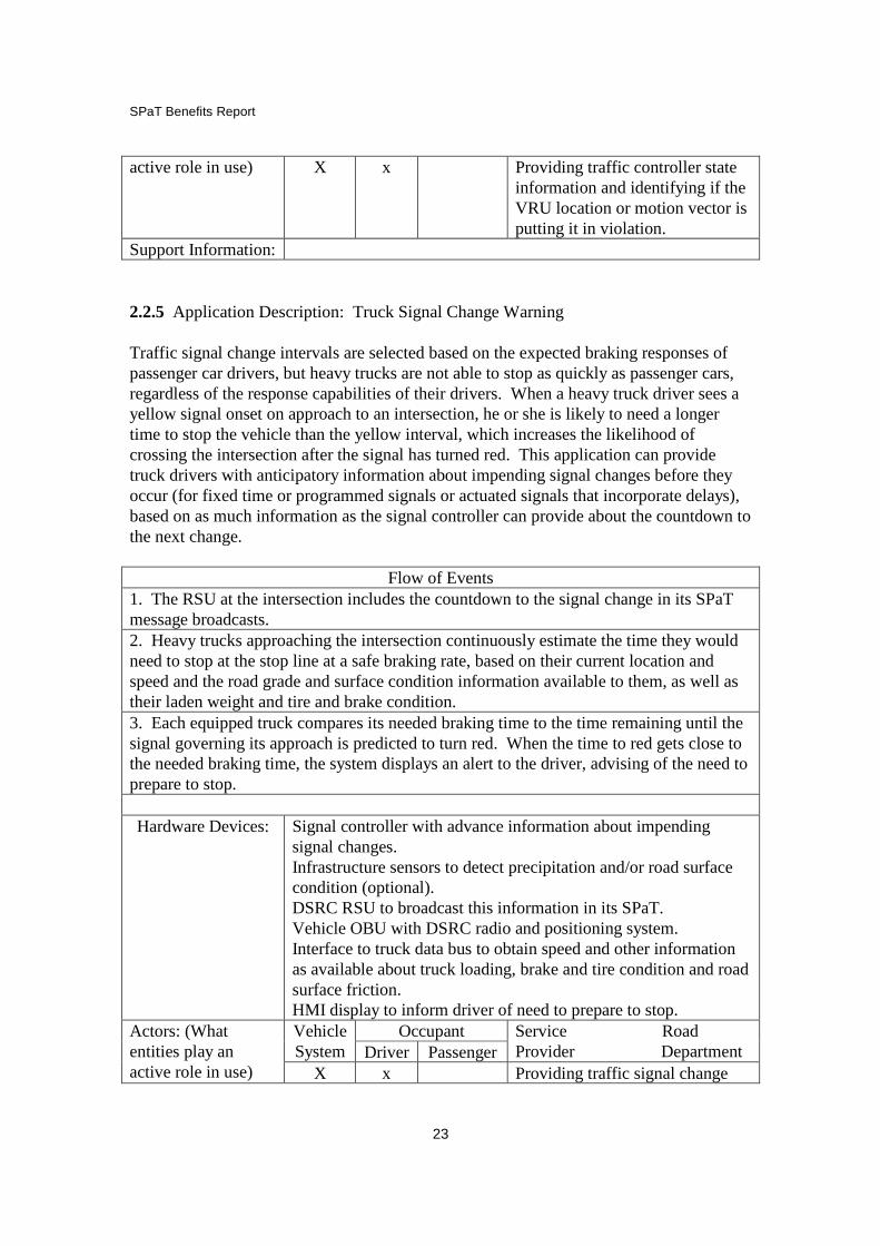
Support Information: 2.2.5 Application Description: Truck Signal Change Warning Traffic signal change intervals are selected based on the expected braking responses of passenger car drivers, but heavy trucks are not able to stop as quickly as passenger cars, regardless of the response capabilities of their drivers. When a heavy truck driver sees a yellow signal onset on approach to an intersection, he or she is likely to need a longer time to stop the vehicle than the yellow interval, which increases the likelihood of crossing the intersection after the signal has turned red. This application can provide truck drivers with anticipatory information about impending signal changes before they occur (for fixed time or programmed signals or actuated signals that incorporate delays), based on as much information as the signal controller can provide about the countdown to the next change.
Flow of Events
1. The RSU at the intersection includes the countdown to the signal change in its SPaT message broadcasts. 2. Heavy trucks approaching the intersection continuously estimate the time they would need to stop at the stop line at a safe braking rate, based on their current location and speed and the road grade and surface condition information available to them, as well as their laden weight and tire and brake condition. 3. Each equipped truck compares its needed braking time to the time remaining until the signal governing its approach is predicted to turn red. When the time to red gets close to the needed braking time, the system displays an alert to the driver, advising of the need to prepare to stop. Hardware Devices: Signal controller with advance information about impending
signal changes. Infrastructure sensors to detect precipitation and/or road surface condition (optional). DSRC RSU to broadcast this information in its SPaT. Vehicle OBU with DSRC radio and positioning system. Interface to truck data bus to obtain speed and other information as available about truck loading, brake and tire condition and road surface friction. HMI display to inform driver of need to prepare to stop.
Occupant Vehicle System Driver Passenger
Service Road Provider Department
Actors: (What entities play an active role in use) X x Providing traffic signal change

SPaT Benefits Report
24
countdown information and potentially road surface condition
Support Information: 2.2.6 Application Description: Transit Signal Priority Transit vehicles (buses or light rail vehicles) approaching a signalized intersection continuously receive SPaT messages from the intersection’s DSRC RSU to include time remaining in the green phase, and this data is used in two ways: (V2I) to extend the green phase if a transit vehicle is projected to enter the intersection within a pre-determined (by algorithm) time, and (I2V) to inform the transit vehicle whether and for how long the signal will be extended. An alternative implementation would be to provide the transit vehicle speed advice to clear the intersection before the red onset for the case with no_TSP or the case with_TSP. This is intended to provide transit vehicle priority at intersections. IntelliDrive for TSP has an ancillary benefit of providing AVL for other (tracking) applications, since highly time-resolved AVL is an intrinsic element to make this work. Another ancillary benefit is that transit times would be better predicted.
Flow of Events 1. Traffic signal controller provides its phase status to the DSRC RSU continuously, and the RSU broadcasts this information frequently in its SPaT message (10 Hz update rate). 2. Each equipped approaching transit vehicle receives SPaT messages. 3. For the applicable phase, the intersection compares the time remaining to the red onset with the time it will take the vehicle in the correct approach to reach the stop line. 4. If it is predicted to reach the stop line after the transition from green within a pre-specified (via algorithm) time, the signal holds its green. System also sends timing and speed information to approaching transit vehicles. Hardware Devices: DSRC radios on intersection and vehicles
Vehicle positioning and heading sensors Interface from traffic signal to DSRC RSU RSE computer (or shared resources) to broadcast SPaT In-vehicle computer for HMI HMI for audible alert to driver
Occupant Vehicle System Driver Passenger
Service Road Provider Department
Actors: (What entities play an active role in use) x x Interface to signal controller to
obtain signal status information Support Information:
2.2.7 Application Description: Arterial Truck Driving

SPaT Benefits Report
25
“IntelliDrive for trucks at intersections” would allow heavy commercial vehicles (e.g., Class 7 or 8) approaching a signalized intersection to continuously receive SPaT messages from the intersection’s DSRC RSU and to provide truck-specific map or other information (e.g., truck crash statistics) to for example accommodate the large turning radii of trucks.
Flow of Events
1. Traffic signal controller provides its phase status to the DSRC RSU continuously, and the RSU broadcasts this information frequently in its SPaT message (10 Hz update rate). 2. Each equipped approaching truck receives SPaT messages. 3. Truck speed advice for smooth driving (minimizing stops) provided. 4. Truck braking distances computed and a truck-specific slow-down profile is provided. 5. Intersection POI (radius constraints, crash statistics, etc.) provided. Hardware Devices: DSRC radios on intersection and vehicles
Vehicle positioning and heading sensors Interface from traffic signal to DSRC RSU RSE computer (or shared resources) to broadcast SPaT In-vehicle computer for HMI HMI for audible and/or visual alert to driver
Occupant Vehicle System Driver Passenger
Service Road Provider Department
Actors: (What entities play an active role in use) x x Interface to signal controller to
obtain signal status information Support Information:
2.2.8 Application Description: EcoDriving
Vehicles approaching communicating signalized intersections (whether they be coordinated in a progression or individually actuated) would continuously receive SPaT messages from the intersection’s DSRC RSU, and they would receive advisories to allow them to progress with minimum fuel consumption and environmental impact. Because each vehicle would have different characteristics and capabilities, this could be both a V2I and I2V application. Some of the “eco-driving” applications include smooth acceleration and speed profiles based on prediction of progressive green phases. Additionally, information on remaining time-in-red is provided. This allows users to dynamically re-route and allows better prediction of travel times, for at least the portion of the travel taken through equipped infrastructure.
Flow of Events 1. Traffic signal controller provides its phase status to the DSRC RSU continuously, and the RSU broadcasts this information frequently in its SPaT message (10 Hz update rate). 2. Each equipped approaching vehicle receives SPaT messages for impending intersection, as well as intersections in predicted route.

SPaT Benefits Report
26
3. Each equipped vehicle calculates at- and near-intersection trajectory, to include minimum (and smooth) acceleration to globally optimize – over the route of equipped intersections – to achieve minimum possible fuel consumption and minimum possible travel time. 4. Each equipped vehicle is given the option to shut off its engine, within constraint of passenger comfort (e.g., with climate controls) Hardware Devices: DSRC radios on intersection and vehicles
Vehicle positioning and heading sensors Interface from traffic signal to DSRC RSU Connected or networked traffic controllers In-vehicle computer for engine shut-off and HMI HMI for visual and/or audio messaging to driver
Occupant Vehicle System Driver Passenger
Service Road Provider Department
Actors: (What entities play an active role in use) x x X Interface to signal controller to
obtain signal status information Support Information:
2.2.9 Application Description: Traffic Signal Control Optimization This application supports the concept of Advanced Traffic Signal Control Algorithms (which is the subject of an FHWA Exploratory Advanced Research project being conducted by Caltrans and PATH) by combining SPaT and comprehensive traffic probe data from IntelliDrive to improve signal control.
Flow of Events
1. Traffic signal controller provides its phase status to the DSRC RSU continuously, and the RSU broadcasts this information frequently in its SPaT message (10 Hz update rate). 2. Each signal receives speed and location data from all equipped vehicles, then adjusts to optimize for a TBD weighting between maximum throughput and minimum on-line fuel consumption. 3. Signal timing is optimized. (Driver HMI optional.) Hardware Devices: DSRC radios on intersection and vehicles
Vehicle positioning and heading sensors Interface from traffic signal to DSRC RSU RSE computer for SPaT
Occupant Vehicle System Driver Passenger
Service Road Provider Department
Actors: (What entities play an active role in use) x x Interface to signal controller to

SPaT Benefits Report
27
obtain signal status information Support Information: 2.2.10 Application Description: “All User” Optimization Vehicle and vulnerable (bicycle and pedestrian) users of signalized intersections would be able to indicate their presence by push button or mobile phone/DSRC or other over-the-air interface to the intersection. The intersection would receive these messages and determine a by-leg and adaptive (within predetermined constraints) timing plan, which would be provided to users, by SPaT messages from the intersection’s DSRC RSU or other over-the-air interface, indicating the time remaining in each phase.
Flow of Events 1. Traffic signal controller provides its phase status to the DSRC RSU continuously, and the RSU broadcasts this information frequently in its SPaT message (10 Hz update rate). 2. User inputs would be balanced within the dynamic or responsive signal timing plan within the controller. 3. User receives SPaT, either via DSRC or other wireless link. For all travelers – pedestrians, bicyclists, transit riders, drivers – better predictability of travel times within the network would be obtained, then provided to the users in a “dynamic traveler information” HMI. Hardware Devices: DSRC radios on intersection and vehicles
Vehicle positioning and heading sensors Interface from traffic signal to DSRC RSU RSE computer for SPaT Driver/pedestrian device for HMI HMI for audible and/or visual alert
Occupant Vehicle System Driver Passenger
Service Road Provider Department
Actors: (What entities play an active role in use) x x Interface to signal controller to
obtain signal status information Support Information: TBD

SPaT Benefits Report
28
Chapter 3: Compendium of ConOps for Each Application ___________________________________________________________________________ In this task, concepts of operation for each of the identified applications shall be developed. Critical elements to be included are scope, system overview, operational environment, supporting environment and operational scenarios. ___________________________________________________________________________ Ten use cases were identified in Chapter 2, based on a broad view of how SPaT data could potentially be used, and including cases where the SPaT is only an ancillary element of a broader application. These ten use cases are summarized in Table 3.1 below, and then the Concepts of Operation for each follow, each beginning on a new page so that they can be treated as stand-alone descriptions. There are many common elements across these concepts of operations, which is fortunate, because it means that multiple applications can be implemented based on deployment of the same set of hardware and common software building blocks. During the final review of project findings, there was a suggestion that we also address how SPaT can be used to improve emergency vehicle responses, especially when they are implementing traffic signal pre-emption, so this has been added as the eleventh use case.
Table 3.1: SPaT Use Cases Resulting from Task 2
Safety • CICAS-V (signal violation warning) • CICAS-TSA (traffic signal adaptation, extending all-red) • Signal status display in vehicle • Vulnerable road user warnings near intersections (pedestrians,
bikes) • Truck signal change warning Mobility • Transit signal priority • Arterial truck driving support • Eco-driving support
• Traffic signal control optimization • “All-User” optimization of traffic control

SPaT Benefits Report
29
3.1 SPaT Con Ops: CICAS – V Scope
• Purpose for Implementing the System: To help inattentive drivers reduce the probability of violating a red traffic signal, making them less likely to cause a crossing-path intersection crash.
• Goals and Objectives: Reducing crossing-path intersection crashes and near misses; making drivers more aware of dangerous intersection approaches;
• Assumptions and Constraints: DSRC-equipped vehicles and intersections, with interface from signal controller to DSRC RSE; assume drivers do not become so dependent on the system’s warnings that they pay less attention than before; assume that warning thresholds are defined to minimize nuisance alerts that could produce inappropriate emergency braking leading to possible rear-end crashes
• Intended Audience: automotive OEMs and suppliers to implement in-vehicle part of system, traffic signal operators, consultants and suppliers to implement infrastructure part of system; safety advocates to encourage adoption of system.
• Logical System Boundaries: signal controller as source of SPaT information to RSE; driver-vehicle interface (audible or haptic) in vehicle to display warnings to driver; CAN bus interface in vehicle to provide some information about vehicle state (speed). This assumes that the CICAS-V system includes the DSRC OBE, with its accurate positioning system and the RSE, with its local map database, within its boundaries.
• Other Boundaries, to include legal and institutional boundaries: Possible interaction with red light enforcement, but this is so politically sensitive that it is probably best avoided.
Vision Intersections with high traffic volumes or with a history of crashes caused by red light runners are equipped with DSRC RSEs that broadcast SPaT messages. Many vehicles are equipped with DSRC RSEs that can receive these messages, and most of these vehicles include CICAS-V functionality, with the software needed to assess the signal violation risk and the DVI to present a salient warning to the driver (audible or haptic and possibly visual as well). User-Oriented Operational Description
• Operational Scenarios: A driver approaches an intersection on a trajectory (speed vs. time and distance) that, if continued, would cause his or her vehicle to cross the stop bar after the signal has turned red. When the vehicle is close enough to the intersection that it appears unlikely that the driver intends to stop (the stop can no longer be achieved with a moderate braking effort), the CICAS-V system issues an audible or haptic warning

SPaT Benefits Report
30
strong enough to seize the driver’s attention. After the driver applies the brakes hard enough that it appears likely the vehicle will stop, the warning is discontinued.
• Users and User Roles The main user is the vehicle driver who receives the warning, but in order for the driver to be able to use CICAS-V, it is necessary for the automotive industry (OEMs and suppliers) to provide the needed hardware and software on their vehicles. Similarly, the intersection operators and their suppliers and consultants need to provide the needed hardware and software for the roadside and the operators need to ensure that it is properly maintained.
• Interactions between Users The infrastructure and vehicle stakeholders need to agree on the standards that govern the data transfers between their systems. Both of them need to communicate with the general public about the operating characteristics of the system and its potential benefits, to encourage its more widespread adoption.
System Overview
• Interfaces (OBE, HMI, Vehicle Data, Traffic Controller): o Signal controller provides its phase and timing information to RSE, which
generates the SPaT message o RSE obtains power from local power source at cabinet o OBE supplies SPaT message (as well as current positioning and heading
data) to in-vehicle CICAS processor, which calculates warning urgency o Vehicle CAN bus supplies other vehicle status information (speed) to
CICAS processor. o CICAS processor supplies warning status (timing, urgency) to HMI for
display to driver
• System Capabilities (Functions) o Predicting vehicle arrival time at stop bar based on its location and speed
and a local map that specifies the stop bar location o Comparing predicted arrival time at stop bar with time of red phase onset
to determine likelihood of violation o Displaying a salient violation alert to the driver (at least audible or haptic)
Operational and Support Environment
• System Hardware o RSE that receives raw current SPaT data from signal controller and
translates it into the SPaT message, then broadcasts that message o OBE that receives SPaT message from RSE and passes it to CICAS-V
processor o GPS receiver on vehicle (may be embedded in OBE) to provide
positioning data
SPaT Benefits Report
31
o CICAS-V processor that estimates violation probability and severity and determines what kind of warning to give to driver and when
o DVI that displays warning to driver (at least audible or haptic, possibly visual as well)
• Software (in addition to basic IntelliDrive DSRC communications software) o In-vehicle Software – CICAS-V warning generation software (threat
assessment, combined with creation of warning message to be displayed in vehicle)
o Roadside Software – RSE software to create SPaT message from inputs received from signal controller.
• Personnel o Support and Training of staff to operate the DSRC network
• Operational Procedures o Periodic testing using agency probe vehicles to verify that RSEs are
generating the required messages
Standardization
• SPaT and local digital map messages • Minimum system performance requirements to ensure user confidence • (Possibly) Warning display characteristics to ensure driver comprehension
Institutional Cooperation
• Standardization of messages • Ensuring adequate maintenance to support continuous operation

SPaT Benefits Report
32
3.2 SPaT Con Ops: CICAS – Traffic Signal Adaptation (TSA) Scope
• Purpose for Implementing the System: To protect innocent drivers from potential crossing-path intersection crashes when other drivers on the cross street violate a red signal near the red onset.
• Goals and Objectives: Reducing crossing-path intersection crashes and near misses.
• Assumptions and Constraints: DSRC-equipped vehicles and intersections, with interface from signal controller to DSRC RSE; signal controller that can implement a dynamically varying all-red interval and signal operator willing to extend the all-red interval occasionally to increase safety; approaching vehicles’ broadcasts of their state information can be received and decoded by RSE; additional detection is highly desirable to detect unequipped vehicles that are violating the red signal;
• Intended Audience: traffic signal operators, consultants and suppliers to implement infrastructure part of system; automotive OEMs and suppliers to implement in-vehicle part of system; safety advocates to encourage adoption of system.
• Logical System Boundaries: signal controller as source of SPaT information to RSE and CICAS-TSA processor; CAN bus interfaces in vehicles to provide some information about vehicle state (speed). This assumes that the CICAS-TSA system includes the DSRC OBE, with its accurate positioning system and the RSE, with its local map database, within its boundaries.
• Other Boundaries, to include legal and institutional boundaries: Possible interaction with red light enforcement to counteract incentives for drivers to violate signals with confidence that they are unlikely to be hit, but this is so politically sensitive that it is probably best avoided.
Vision Intersections with high traffic volumes or with a history of crashes caused by red light runners are equipped with DSRC RSEs that broadcast SPaT messages. Many vehicles are equipped with DSRC RSEs that can receive these messages, and can broadcast their own state information so that the intersection controller becomes aware of imminent violations. Using a combination of data about approaching vehicles from these vehicles’ own broadcasts and from infrastructure-based detectors, the CICAS-TSA processor identifies imminent violations early in the red phase and requests the signal controller to extend the all-red interval for the crossing traffic until after the violating vehicle has passed.

SPaT Benefits Report
33
User-Oriented Operational Description
• Operational Scenarios: A driver approaches an intersection on a trajectory (speed vs. time and distance) that, if continued, would cause his or her vehicle to cross the stop bar after the signal has turned red. When the vehicle is close enough to the intersection that it appears unlikely that the driver intends to stop (the stop can no longer be achieved with a moderate braking effort), the CICAS-TSA system decides to extend the all-red interval so that the crossing traffic does not start up until the violating vehicle has passed through the intersection.
• Users and User Roles The main user is the traffic signal operator, who implements the extension of the all-red interval. However, the main beneficiary is the driver of the vehicle approaching on a crossing path relative to the violator, and who therefore avoids being hit by the violator. This function works best when the violating vehicle is equipped so that it can provide its trajectory data (“Here I am” (HIA)), which means that the effectiveness is influenced by the completeness of market penetration of equipped vehicles, so it is helpful for the automotive industry (OEMs and suppliers) to provide the needed HIA hardware and software on their vehicles. Similarly, the intersection operators and their suppliers and consultants need to provide the needed hardware and software for the roadside and the operators need to ensure that it is properly maintained and that they are willing to extend their all-red intervals when necessary.
• Interactions between Users The infrastructure and vehicle stakeholders need to agree on the standards that govern the data transfers between their systems. Both of them need to communicate with the general public about the operating characteristics of the system and its potential benefits, to encourage its more widespread adoption.
System Overview
• Interfaces (OBE, HMI, Vehicle Data, Traffic Controller): o Signal controller provides its phase and timing information to RSE, which
generates the SPaT message o RSE obtains power from local power source at cabinet o RSE receives approaching vehicles’ trajectory information from their
OBEs and supplies it to CICAS-TSA processor o Vehicle CAN bus supplies vehicle status information (speed, location) to
OBE, which broadcasts it. o CICAS-TSA processor predicts imminent violation and then supplies all-
red extension request to signal controller.
• System Capabilities (Functions) implemented on roadside o Predicting vehicle arrival time at stop bar based on its location and speed

SPaT Benefits Report
34
o Comparing predicted arrival time at stop bar with time of red phase onset to determine likelihood of violation
o Providing all-red extension request to signal controller. Operational and Support Environment
• System Hardware o RSE that receives raw current SPaT data from signal controller and
translates it into the SPaT message, then broadcasts that message o OBE that receives vehicle position and speed data from GPS receiver and
in-vehicle sensors, and then broadcasts it o GPS receiver on vehicle (may be embedded in OBE) to provide
positioning data o (Optional, but highly desirable) Vehicle detectors on intersection
approaches to detect violating vehicles that are not equipped with OBEs o CICAS-TSA processor that estimates violation probability and severity
and determines how long an all-red extension to request from signal controller
• Software (in addition to basic IntelliDrive DSRC communications software) o In-vehicle Software – none o Roadside Software – CICAS-TSA processor software to detect violation
and determine how long an all-red extension to request from signal controller.
• Personnel o Support and Training of staff to operate the DSRC network
• Operational Procedures o Periodic testing using agency probe vehicles to verify that RSEs are
receiving their transmissions
Standardization
• SPaT and local digital map messages • Limits on duration of all-red extension • (If politically feasible) Requirements on use of red light enforcement systems to
discourage violators who know that their risk of being hit is reduced significantly. Institutional Cooperation
• Standardization of messages • Ensuring adequate maintenance to support continuous operation • Uniform policies on duration of all-red extension and combinations with red light
enforcement systems.

SPaT Benefits Report
35
3.3 SPaT Con Ops: Signal Status Display in Vehicle Scope
• Purpose for Implementing the System: To inform drivers (via an in-vehicle display) about current signal status and potentially about the time remaining to the next phase.
• Goals and Objectives: Increasing driver awareness of signal status and potentially also enabling them to avoid dilemma zone problems and signal violations.
• Assumptions and Constraints: DSRC-equipped vehicles and intersections, with interface from signal controller to DSRC RSE; display in vehicle shows current phase as a minimum (probably visual); display in vehicle may potentially also show countdown, either numerical or graphical, of time remaining in current phase.
• Intended Audience: automotive OEMs and suppliers to implement in-vehicle part of system, traffic signal operators, consultants and suppliers to implement infrastructure part of system; vehicle purchasers to choose to purchase the option.
• Logical System Boundaries: signal controller as source of SPaT information to RSE; driver-vehicle interface (visual) in vehicle to display signal phase to driver; This assumes that the signal status display system includes the DSRC OBE, with its positioning system and the RSE, with its local map database, within its boundaries.
• Other Boundaries, to include legal and institutional boundaries: traffic safety, legal and human factors communities to consider wisdom of including countdown function.
Vision Vehicles are equipped with DSRC RSEs and displays that can show the current signal phase, enhancing driver awareness of signal phase, and possibly impending phase changes, so that they can make safer and more confident decisions on approaching signalized intersections. User-Oriented Operational Description
• Operational Scenarios: A driver approaching a signalized intersection receives a display of the current signal phase on the vehicle’s instrument panel so that if the driver is looking at something else on the instrument panel rather than looking ahead at the intersection he or she will remain aware of the current signal phase. If the phase changes while the driver is looking down, that phase change will become visible immediately on the display. Optionally, the display may also show how much time is expected to remain on the current phase, either through a numerical countdown or a graphical icon.

SPaT Benefits Report
36
• Users and User Roles The main user is the vehicle driver who sees the display, but in order for the driver to be able to use this, it is necessary for the automotive industry (OEMs and suppliers) to provide the needed hardware and software on their vehicles. Similarly, the intersection operators and their suppliers and consultants need to provide the needed hardware and software for the roadside and the operators need to ensure that it is properly maintained.
• Interactions between Users The infrastructure and vehicle industry stakeholders need to agree on the standards that govern the data transfers between their systems. The vehicle manufacturers and vendors need to communicate with the general public about the operating characteristics of the system to develop market interest.
System Overview
• Interfaces (OBE, HMI, Vehicle Data, Traffic Controller): o Signal controller provides its phase and timing information to RSE, which
generates the SPaT message o RSE obtains power from local power source at cabinet o OBE supplies SPaT message (as well as current heading data) to in-vehicle
processor, which generates appropriate display outputs o HMI display signal status to driver
• System Capabilities (Functions) o Identifying vehicle heading direction approaching intersection, so that it
knows which signal phase is relevant to its approach o Generating display of signal phase based on SPaT message that applies to
its approach direction. Operational and Support Environment
• System Hardware o RSE that receives raw current SPaT data from signal controller and
translates it into the SPaT message, then broadcasts that message o OBE that receives SPaT message from RSE and passes it to display
processor o Compass on vehicle (may be embedded in OBE) to provide heading angle o Processor that associates vehicle heading angle with the signal phase that
is appropriate to that approach direction, so that it can determine what input to provide to DVI
o DVI that displays signal phase to driver (visual)
• Software (in addition to basic IntelliDrive DSRC communications software) o In-vehicle Software – code to associate vehicle heading angle with
relevant signal phase

SPaT Benefits Report
37
o Roadside Software – RSE software to create SPaT message from inputs received from signal controller.
• Personnel o Support and Training of staff to operate the DSRC network
• Operational Procedures o Periodic testing using agency probe vehicles to verify that RSEs are
generating the required messages
Standardization • SPaT and local digital map messages • Minimum requirements on display conspicuity
Institutional Cooperation
• Standardization of messages • Ensuring adequate maintenance to support continuous operation

SPaT Benefits Report
38
3.4 SPaT Con Ops: Warnings about Vulnerable Road Users (VRUs) near Intersections Scope
• Purpose for Implementing the System: To reduce the likelihood that a driver will hit a bicyclist or pedestrian near an intersection, by making drivers aware of the presence of these vulnerable road users (VRUs).
• Goals and Objectives: Provide drivers with warnings about the presence of pedestrians and bicyclists in their travel path when they are driving near signalized intersections.
• Assumptions and Constraints: DSRC-equipped vehicles and intersections, with interface from signal controller to DSRC RSE; assume drivers do not become so dependent on the system’s warnings that they pay less attention than before; assume that warning thresholds are defined to minimize false and nuisance alerts that could cause drivers to lose trust in the warnings; assume VRUs are equipped with “here I am” wireless broadcast devices that can communicate to the intersection.
• Intended Audience: automotive OEMs and suppliers to implement in-vehicle part of system, traffic signal operators, consultants and suppliers to implement infrastructure part of system; bicycling and pedestrian interest groups and general traffic safety advocates to encourage adoption of system.
• Logical System Boundaries: signal controller as source of SPaT information to RSE; nomadic device carried by VRU to communicate its location, speed and heading direction to the RSE, driver-vehicle interface (audible or haptic) in vehicle to display warnings to driver; CAN bus interface in vehicle to provide some information about vehicle state (heading and possibly speed). This assumes that the system includes the DSRC OBE, with its accurate positioning system and the RSE, with its local map database, within its boundaries.
• Other Boundaries, to include legal and institutional boundaries: Possible interactions with enforcement of pedestrian and bicycling rules of the road.
Vision Pedestrians and bicyclists carry nomadic devices that periodically broadcast their location, heading direction and speed of travel (“here I am” messages). Intersections with high volumes of pedestrian and/or bicyclist traffic or with a history of crashes involving VRUs are equipped with capabilities to receive “here I am” messages from nearby VRUs and with DSRC RSEs that broadcast warnings about VRU violations and the presence of other VRUs that are in potential danger of being hit by vehicles. Many vehicles are equipped with DSRC RSEs that can receive these messages, and the software needed to assess the risk of hitting any of the VRUs and the DVI to present a salient warning to the driver (audible or haptic and possibly visual as well).

SPaT Benefits Report
39
User-Oriented Operational Description
• Operational Scenarios: A VRU walking or bicycling in the vicinity of an intersection enters the road surface where vehicles drive. A nomadic device carried by this VRU periodically broadcasts a “here I am” message, which is received by a roadside receiver (DSRC or cellular telephony based). A driver approaches the intersection legally on a trajectory that, if continued, would cause his or her vehicle to have a close encounter with the VRU. The system issues an audible or haptic warning strong enough to seize the driver’s attention. After the driver applies the brakes hard enough that it appears likely the vehicle will avoid hitting the VRU, or the VRU changes course away from the conflict, the warning is discontinued.
• Users and User Roles The main users are the vehicle driver who receives the warning, and the VRU who generates the warning and is thereby protected from harm. In order for the driver to be able to use the system, it is necessary for the automotive industry (OEMs and suppliers) to provide the needed hardware and software on their vehicles. In order for the VRU to be able to generate the warning, it is necessary for suppliers of nomadic devices to include the capability of generating the “here I am” message. Similarly, the intersection operators and their suppliers and consultants need to provide the needed hardware and software for the roadside and the operators need to ensure that it is properly maintained.
• Interactions between Users The infrastructure, nomadic device and vehicle stakeholders need to agree on the standards that govern the data transfers between their systems. They all need to communicate with the general public about the operating characteristics of the system and its potential benefits, to encourage its more widespread adoption in both vehicles and nomadic devices.
System Overview
• Interfaces (OBE, HMI, Vehicle Data, Traffic Controller): o VRU’s nomadic device broadcasts its location, speed and heading
information, which is received by RSE. o Signal controller provides its phase and timing information to RSE, which
broadcasts the SPaT message and VRU hazard alert o RSE obtains power from local power source at cabinet o OBE receives SPaT message and VRU hazard alert and supplies it to in-
vehicle processor o Processor combines SPaT, VRU hazard alert and vehicle trajectory data to
determine the need to generate a warning to HMI for display to driver.

SPaT Benefits Report
40
• System Capabilities (Functions) o Infrastructure determining whether a VRU is on a trajectory that is likely
to put it in danger of being hit by a vehicle (for example, by violating a signal)
o Vehicle system comparing infrastructure assessment of VRU trajectory with its own trajectory to determine need to alert driver to the hazard.
o Displaying a salient VRU alert to the driver (at least audible or haptic). Operational and Support Environment
• System Hardware o RSE that receives raw current SPaT data from signal controller and
translates it into the SPaT message, then broadcasts that message o Nomadic device that generates VRU “here I am” messages when VRU is
in a potentially dangerous location (in the vehicle traveling way, without benefit of signal phase protection)
o RSE that receives the VRU “here I am” messages and compares them with SPaT data to determine hazard level.
o OBE that receives SPaT message and VRU hazard information from RSE and passes it to in-vehicle processor
o GPS receiver on vehicle (may be embedded in OBE) to provide positioning data
o In-vehicle processor that estimates VRU conflict severity and determines what kind of warning to give to driver and when
o DVI that displays warning to driver (at least audible or haptic, possibly visual as well)
• Software (in addition to basic IntelliDrive DSRC communications software) o In-vehicle Software – VRU warning generation software (threat
assessment, combined with creation of warning message to be displayed in vehicle)
o Roadside Software – RSE software to create SPaT message from inputs received from signal controller and to determine VRU hazard level based on the “here I am” messages received from VRUs.
• Personnel o Support and Training of staff to operate the DSRC network
• Operational Procedures o Periodic testing using agency probe vehicles and agency staff as VRUs to
verify that RSEs are generating the required messages.
Standardization
• SPaT and local digital map messages

SPaT Benefits Report
41
• VRU “here I am” messages, based on Basic Safety Message, but with potential VRU extensions
• Minimum system performance requirements (false positive and false negative rates) to ensure user confidence
• (Possibly) Warning display characteristics to ensure driver comprehension Institutional Cooperation
• Standardization of messages • Ensuring adequate maintenance to support continuous operation • Coordination with suppliers of nomadic devices.

SPaT Benefits Report
42
3.5 SPaT Con Ops: Truck Signal Change Warning Scope
• Purpose for Implementing the System: To inform heavy truck drivers (via an in-vehicle display) about the time remaining to the next signal phase so that they can determine how early they should start decelerating in order to be able to stop safely, reducing the risk of violating a red signal because of their limited stopping ability.
• Goals and Objectives: Increasing truck driver awareness of impending signal changes to enable them to better avoid dilemma zone problems and signal violations that could otherwise be caused by their limited deceleration capabilities.
• Assumptions and Constraints: DSRC-equipped vehicles and intersections, with interface from signal controller to DSRC RSE; display in vehicle may show current phase and countdown, either numerical or graphical, of time remaining in current phase, or may use additional information (road surface condition and grade, truck loading, etc.) to alert the driver it is advisable to start braking early.
• Intended Audience: truck OEMs and suppliers to implement in-vehicle part of system, traffic signal operators, consultants and suppliers to implement infrastructure part of system; truck drivers and fleets to choose to purchase the option.
• Logical System Boundaries: signal controller as source of SPaT information to RSE; infrastructure-based sensors to supply road surface friction information to RSE; in-vehicle sensors or database to supply loading and/or brake condition data in support of advanced alert; driver-vehicle interface (visual) in vehicle to display signal countdown or stopping advisory to driver; This assumes that the signal change display system includes the DSRC OBE, with its positioning system and the RSE, with its local map database, within its boundaries.
• Other Boundaries, to include legal and institutional boundaries: traffic safety, legal and human factors communities to consider implications of countdown and early stopping advisory functions.
Vision Heavy trucks are equipped with DSRC OBEs and displays that can show the signal phase countdown or stopping advisory, so that truck drivers can make safer and more confident decisions about stopping when approaching signalized intersections. User-Oriented Operational Description
• Operational Scenarios: A truck driver approaching a signalized intersection receives a display of the time remaining in the current signal phase on the vehicle’s instrument panel so that he or

SPaT Benefits Report
43
she will be able to judge in advance whether to slow down in anticipation of a red phase. In addition, the driver may be alerted that he or she needs to slow down prior to the red phase when the in-vehicle system determines that the truck’s stopping time (based on road surface conditions and truck condition and loading) exceeds the time remaining before the red onset.
• Users and User Roles The main user is the truck driver who sees the display, but in order for the driver to be able to use this, it is necessary for the trucking industry (fleet operators, OEMs and suppliers) to provide the needed hardware and software on their vehicles. Similarly, the intersection operators and their suppliers and consultants need to provide the needed hardware and software for the roadside and the operators need to ensure that it is properly maintained.
• Interactions between Users The infrastructure and trucking industry stakeholders need to agree on the standards that govern the data transfers between their systems. The truck manufacturers and vendors need to communicate with their customers (fleets and drivers) about the operating characteristics of the system to develop market interest.
System Overview
• Interfaces (OBE, HMI, Vehicle Data, Traffic Controller): o Signal controller provides its phase and timing information to RSE, which
generates the SPaT message o RSE obtains power from local power source at cabinet o OBE supplies SPaT message (as well as current heading data) to in-vehicle
processor o In-vehicle processor combines SPaT message with vehicle location, speed
and heading data and potentially additional data about vehicle stopping capability to generate appropriate display outputs
o HMI displays signal countdown or alert of need to decelerate to driver
• System Capabilities (Functions) o Identifying truck heading direction approaching intersection, so that it
knows which signal phase is relevant to its approach o Estimating time remaining for truck to reach stop bar o Estimating time needed for truck to stop safely based on current conditions o Generating display of signal countdown and/or stopping advisory.
Operational and Support Environment
• System Hardware o RSE that receives raw current SPaT data from signal controller and
translates it into the SPaT message, then broadcasts that message

SPaT Benefits Report
44
o OBE that receives SPaT message (and local digital map) from RSE and passes it to in-vehicle processor
o Compass on vehicle (may be embedded in OBE) to provide heading angle o In-vehicle processor that associates vehicle heading angle with the signal
phase that is appropriate to that approach direction and obtains vehicle speed and location data to estimate time to reach stop bar, and other vehicle and road condition data to estimate needed stopping time
o DVI that displays signal countdown or stopping alert to driver
• Software (in addition to basic IntelliDrive DSRC communications software) o In-vehicle Software – code to associate vehicle heading angle with
relevant signal phase, to estimate time to stop bar and time needed to stop, and to determine what kind of alert to issue to driver
o Roadside Software – RSE software to create SPaT message from inputs received from signal controller.
• Personnel o Support and Training of staff to operate the DSRC network
• Operational Procedures o Periodic testing using probe trucks to verify that RSEs are generating the
required messages
Standardization
• SPaT and local digital map messages • Minimum requirements on display functionality
Institutional Cooperation
• Standardization of messages • Ensuring adequate maintenance to support continuous operation

SPaT Benefits Report
45
3.6 SPaT Con Ops: Transit Signal Priority Scope
• Purpose for Implementing the System: To reduce the delays that transit buses and their passengers encounter at traffic signals by giving them the opportunity to request higher priority for green time allocation. This could give each bus passenger closer to the same value as each car driver in the allocation of green time.
• Goals and Objectives: Reducing the number of times that transit buses need to stop for red signals and possibly also reducing the durations of those stops so that bus travel times can become more competitive with private personal car travel times. This has the ancillary effects of improving the transit bus mode share and reducing the excess energy consumption and pollutant emissions associated with the extra stops that are avoided.
• Assumptions and Constraints: DSRC-equipped buses and intersections, with interface from DSRC RSE to signal controller; display in vehicle may show driver the status of his bus’ priority request. Priority could be allocated under a variety of possible conditions, such as extending a stale green or shortening a red phase, and the strength of the priority request could be adjusted based on considerations such as bus occupancy, how far the bus is from its nominal schedule, and the needs of its passengers to connect to other buses or trains.
• Intended Audience: transit agencies and their suppliers to implement in-vehicle part of system, traffic signal operators, consultants and suppliers to implement infrastructure part of system; transit riders and advocates to encourage adoption.
• Logical System Boundaries: signal controller as source of SPaT information to RSE; in-vehicle sensors to supply passenger counts; in-vehicle or central database to provide nominal bus schedule. This assumes that the TSP system includes the DSRC OBE, with its positioning system and the RSE, with its local map database, within its boundaries.
• Other Boundaries, to include legal and institutional boundaries: traffic safety and driver advocacy groups to consider potential for adverse effects.
Vision Transit buses are equipped with DSRC OBEs which broadcast their location, direction of travel and potentially other relevant information (passenger loading, schedule status), so that DSRC RSEs at signalized intersections can provide this information to their local signal controllers, enabling them to give higher priority to the buses so that their delays and number of stops are reduced. User-Oriented Operational Description
• Operational Scenarios:

SPaT Benefits Report
46
A transit bus approaching a signalized intersection broadcasts its location, speed, direction of travel and potentially other relevant information (passenger loading, its timing relative to schedule). The signal controller receives this information and uses it to determine what priority to assign to the bus, which could be manifested as an extension of a stale green phase or the shortening of a current red phase. The intersection RSE broadcasts the SPaT information, which would include any changes effected by this transit signal priority (TSP) function, and those changes could potentially be displayed to the bus driver so that s/he would obtain feedback about the effectiveness of the TSP request from his/her bus.
• Users and User Roles The main user is the bus driver who receives the signal priority, but this also has direct benefits to the bus passengers who save time and stops and to the transit agency, which gains increased productivity from its fleet, reduced fuel and maintenance expenses, and potentially increased ridership. The transit agency role is to decide to equip its buses with the TSP function and to negotiate with the local signal operating agency regarding implementation of TSP. Similarly, the intersection operators and their suppliers and consultants need to provide the needed hardware and software for the roadside and the operators need to ensure that it is properly maintained.
• Interactions between Users The traffic signal infrastructure and transit agency stakeholders need to agree on the standards that govern the data transfers between their systems and on the specific operating protocols that will respect the competing needs of both.
System Overview
• Interfaces (OBE, HMI, Vehicle Data, Traffic Controller): o Signal controller provides its phase and timing information to RSE, which
generates the SPaT message o RSE obtains power from local power source at cabinet o OBE broadcasts bus location, speed, direction of travel and potentially
additional information relevant to determining how much priority should be assigned to each bus
o RSE provides bus priority request information to local traffic signal controller
o OBE receives SPaT message, which it may combine with historical information to provide display to driver about how signal cycle is being changed to give additional priority to the bus.
o HMI displays signal countdown or signal status change information to bus driver
• System Capabilities (Functions) o Comparing bus’s current location and time with scheduled time to be at
this location to determine its timing relative to schedule

SPaT Benefits Report
47
o Identifying bus heading direction approaching intersection, so that it can tell the signal controller which approach needs signal priority
o Estimating time remaining for bus to reach stop bar so that it can request sufficient green extension time to safely enter the intersection
o Generating request to traffic signal controller for a specific change to its current timing plan
o Generating display for bus driver of signal status or status changes in response to TSP request.
Operational and Support Environment
• System Hardware o RSE that receives raw current SPaT data from signal controller and
translates it into the SPaT message, then broadcasts that message, and also receives augmented “Here I am” messages from approaching buses;
o OBE that broadcasts “Here I am” message from bus, augmented with additional bus-specific data, and receives SPaT message (and local digital map) from RSE and passes it to in-vehicle processor;
o Processor in signal control cabinet that uses “Here I am” messages from approaching buses to generate requests for transit priority to traffic signal controller;
o (Optional) In-vehicle sources of additional bus-specific data, such as automatic passenger counter and bus schedule database
o (Optional) DVI that displays signal countdown or signal priority change implementation to driver.
• Software (in addition to basic IntelliDrive DSRC communications software) o In-vehicle Software – code to integrate bus-specific data with “Here I am”
message for broadcast by OBE. o Roadside Software – code to combine data from all approaching buses
with data about local traffic conditions to determine what changes to request of traffic signal controller to implement transit priority.
• Personnel o Support and Training of staff to operate and maintain the DSRC network
and in-vehicle components and to determine what adjustments are needed to balance the needs of transit service and local traffic control.
• Operational Procedures o Periodic testing using probe buses to verify that priority is being
implemented correctly. o Collection and analysis of traffic data to ensure that traffic conditions are
not being degraded unnecessarily.
Standardization
• SPaT and local digital map messages • Interfaces to traffic signal controllers to request their changes

SPaT Benefits Report
48
Institutional Cooperation
• Developing agreement between transit bus and traffic signal operating agencies about how to balance their respective needs and priorities
• Standardization of messages • Ensuring adequate maintenance to support continuous operation.

SPaT Benefits Report
49
3.7 SPaT Con Ops: Arterial Truck Driving Scope
• Purpose for Implementing the System: To facilitate heavy truck driving in urban areas by helping truck drivers adjust their speed to minimize the number of stops they need to make at signalized intersections and to make them more aware of potential hazards in their path (geometric restrictions or high truck crash locations).
• Goals and Objectives: Advising truck drivers of the best speed for them to travel to maintain a smooth speed and minimize the frequency of having to stop for red signals. Advising truck drivers about hazardous situations they are approaching, such as tight turn restrictions or locations with a history of a significant frequency of truck-involved crashes, so that they can heighten their awareness.
• Assumptions and Constraints: DSRC-equipped trucks and intersections, with interface from signal controller to DSRC RSE; display in truck tells driver what speed will minimize need to stop for red signals (while still requiring driver to be responsible for avoiding potential crashes with slower other vehicles); speed advisory could optionally be extended to be an adaptive cruise control set speed; unspecified display (visual or audible) could inform driver about general truck-specific hazardous conditions ahead (based on historical or geometric data).
• Intended Audience: truck OEMs and suppliers to implement in-vehicle part of system, traffic signal operators, consultants and suppliers to implement infrastructure part of system; truck drivers and fleets to choose to purchase the option.
• Logical System Boundaries: signal controller as source of SPaT information to RSE; driver-vehicle interface (visual) in vehicle to display advisory speed to driver; adaptive cruise control input to receive set speed recommendation. This assumes that the arterial truck support system includes the DSRC OBE, with its positioning system and the RSE, with its local map database, within its boundaries.
• Other Boundaries, to include legal and institutional boundaries: traffic safety, legal, law enforcement and human factors communities to consider safety implications of speed advisory function, especially in case a crash occurs involving a driver of an equipped truck. Traffic management and enforcement communities to consider traffic flow implications of a truck potentially driving significantly below the posted speed limit.
Vision Heavy trucks are equipped with DSRC OBEs and displays that can show the recommended driving speed, so that truck drivers can drive as efficiently and smoothly as possible through urban areas with signalized intersections. This would include smooth deceleration profiles on intersection approaches where stopping is unavoidable, to
SPaT Benefits Report
50
improve safety and environmental impacts. The displays can also alert the drivers as they approach locations where they need to exercise extra caution because of geometric restrictions (tight turns) or a history of many truck-involved crashes. User-Oriented Operational Description
• Operational Scenarios: A truck driver driving along a corridor of signalized intersections receives a continually updated display indicating the recommended speed to drive in order to continue with a minimum likelihood of having to stop for a red signal. If a stop is unavoidable, the system will provide a recommended smooth braking profile matched to the condition of the truck. In addition, the driver may be alerted that he or she needs to pay extra attention because of a difficult road geometry (tight curve) or a location where many trucks have been involved in crashes in the past. Optionally, the speed recommendation could be extended to serve as the set speed for an adaptive cruise control system, enabling the truck to maintain the recommended speed without active driver intervention.
• Users and User Roles The main user is the truck driver who sees and uses the display, but in order for the driver to be able to use this, it is necessary for the trucking industry (fleet operators, OEMs and suppliers) to provide the needed hardware and software on their vehicles. Similarly, the intersection operators and their suppliers and consultants need to provide the needed hardware and software for the roadside and the operators need to ensure that it is properly maintained.
• Interactions between Users The infrastructure and trucking industry stakeholders need to agree on the standards that govern the data transfers between their systems. The truck manufacturers and vendors need to communicate with their customers (fleets and drivers) about the operating characteristics of the system to develop market interest.
System Overview
• Interfaces (OBE, HMI, Vehicle Data, Traffic Controller): o Signal controller provides its phase and timing information to RSE, which
generates the SPaT message; o Local or centralized database of crash history and challenging road
geometry is provided to RSE, which includes the locally relevant elements in its broadcasts to all approaching trucks;
o RSE obtains power from local power source at cabinet o OBE supplies SPaT message (as well as current heading data) to in-vehicle
processor

SPaT Benefits Report
51
o In-vehicle processor combines SPaT message with vehicle location, speed and heading data to generate appropriate recommended speed display outputs
o HMI displays recommended speed to driver o (Optionally) Recommended speed value is supplied to adaptive cruise
control system as its dynamically varying set speed.
• System Capabilities (Functions) o Identifying truck heading direction approaching intersection, so that it
knows which signal phase is relevant to its approach o Estimating time remaining for truck to reach stop bars at all upcoming
intersections along the corridor o (If the truck driver is using a route guidance system) Extend the arrival
time estimates to all upcoming intersections along the intended route. o Comparing truck stop bar arrival times with upcoming signal phases and
using those comparisons to define the recommended profile of speeds for the truck to follow to minimize fuel consumption and emissions, within safety and practicality constraints.
o Generating display of current recommended speed (and potentially upcoming speed changes as well if this can be done without being distracting).
Operational and Support Environment
• System Hardware o RSE that receives raw current SPaT data from signal controller and
translates it into the SPaT message, then broadcasts that message o OBE that receives SPaT message (and local digital map) from RSE and
passes it to in-vehicle processor o Compass on vehicle (may be embedded in OBE) to provide heading angle o In-vehicle processor that associates truck heading angle with the signal
phase that is appropriate to that approach direction and obtains truck speed and location data to estimate time to reach stop bar, and then compares this with signal phase data to determine speed changes needed for truck to avoid having to stop for a red signal or to provide a smooth deceleration if a stop is unavoidable.
o DVI that displays recommended speed to driver
• Software (in addition to basic IntelliDrive DSRC communications software) o In-vehicle Software – code to associate vehicle heading angle with
relevant signal phase, to estimate time to stop bar and to define recommended speed profile
o Roadside Software – RSE software to create SPaT message from inputs received from signal controller.
• Personnel o Support and Training of staff to operate the DSRC network

SPaT Benefits Report
52
• Operational Procedures o Periodic testing using probe trucks to verify that RSEs are generating the
required messages and that the in-vehicle hardware and software are enabling the trucks to avoid excessive stopping at red signals.
Standardization
• SPaT and local digital map messages • Minimum requirements on display functionality • Constraints on recommended speed ranges and rates of change of recommended
speed. Institutional Cooperation
• Standardization of messages • Ensuring adequate maintenance to support continuous operation • Cooperation among trucking industry, traffic management and law enforcement to
agree on recommended speed ranges and rules governing definition of speed changes.

SPaT Benefits Report
53
3.8 SPaT Con Ops: Eco Driving Scope
• Purpose for Implementing the System: To enable drivers to follow speed profiles that will minimize their fuel consumption and emissions, by maintaining as close to a constant speed as possible and minimizing stops in signalized arterial networks. In the longer term, enable system-wide eco-driving strategies by adjusting signal cycles to minimize speed changes and stops for all.
• Goals and Objectives: Advising drivers of the best speed for them to travel to maintain a smooth speed profile and minimize the frequency of stops for red signals. When they do need to stop, inform the vehicles about the length of the stop so that the engine can be shut down until it is needed to accelerate at the next green onset.
• Assumptions and Constraints: DSRC-equipped vehicles and intersections, with interface from signal controller to DSRC RSE; display in vehicle tells driver what speed will minimize need to stop for red signals (while still requiring driver to be responsible for avoiding potential crashes with slower other vehicles); speed advisory could optionally be extended to be an adaptive cruise control set speed; vehicle can automatically shut down and re-start engine so that it does not need to idle while the vehicle is stopped at a red signal; with high vehicle market penetration, the vehicle data can be used to adjust the signal timing as well to encourage eco-driving for all.
• Intended Audience: automotive OEMs and suppliers to market and implement the in-vehicle part of system, traffic signal operators, consultants and suppliers to implement infrastructure part of system; vehicle owners to choose to purchase the option; environmental interest groups to encourage both vehicle and infrastructure system investments.
• Logical System Boundaries: signal controller as source of SPaT information to RSE; driver-vehicle interface (visual) in vehicle to display advisory speed to driver; adaptive cruise control input to receive set speed recommendation. This assumes that the Eco Driving system includes the DSRC OBE, with its positioning system and the RSE, with its local map database, within its boundaries.
• Other Boundaries, to include legal and institutional boundaries: traffic safety, legal, law enforcement and human factors communities to consider safety implications of speed advisory function, especially in case a crash occurs involving a driver of an equipped vehicle. Traffic management and enforcement communities to consider traffic flow implications of vehicles potentially driving significantly below the posted speed limit.
Vision

SPaT Benefits Report
54
Most vehicles are equipped with DSRC OBEs and displays that can show the recommended driving speed, so that drivers can drive as efficiently and smoothly as possible through urban areas with signalized intersections. This would include smooth deceleration profiles on intersection approaches where stopping is unavoidable, to improve safety and environmental impacts. As the vehicle market penetration grows, the vehicles can provide feedback to the signal control system so that the signal timing can be adjusted to promote eco-driving for all vehicles, minimizing speed changes and number of stops for all. User-Oriented Operational Description
• Operational Scenarios: A driver driving along a corridor of signalized intersections receives a continually updated display indicating the recommended speed to drive in order to continue with a minimum likelihood of having to stop for a red signal. If a stop is unavoidable, the system will provide a recommended smooth braking profile and will also inform the vehicle when the red phase will end, enabling the engine to be shut down throughout the stop. Optionally, the speed recommendation could be extended to serve as the set speed for an adaptive cruise control system, enabling the vehicle to maintain the recommended speed without active driver intervention. • Users and User Roles The main user is the driver who sees and uses the display, but in order for the driver to be able to use this, it is necessary for the automotive industry (OEMs and suppliers) to market and provide the needed hardware and software on their vehicles. Similarly, the intersection operators and their suppliers and consultants need to provide the needed hardware and software for the roadside and the operators need to ensure that it is properly maintained. Environmental interest groups could also be advocates to the public agencies and the consumers, encouraging them to invest in the Eco-driving system. • Interactions between Users The infrastructure and vehicle industry stakeholders need to agree on the standards that govern the data transfers between their systems. The manufacturers and vendors need to communicate with their customers (car buyers) about the benefits of the system to develop market interest.
System Overview
• Interfaces (OBE, HMI, Vehicle Data, Traffic Controller): o Signal controller provides its phase and timing information to RSE, which
generates the SPaT message; o RSE obtains power from local power source at cabinet o OBE supplies SPaT message (as well as current heading data) to in-vehicle
processor

SPaT Benefits Report
55
o In-vehicle processor combines SPaT message with vehicle location, speed and heading data to generate appropriate recommended speed display outputs
o HMI displays recommended speed to driver o (Optionally) Recommended speed value is supplied to adaptive cruise
control system as its dynamically varying set speed.
• System Capabilities (Functions) o Identifying vehicle heading direction approaching intersection, so that it
knows which signal phase is relevant to its approach o Estimating time remaining for vehicle to reach stop bars at all upcoming
intersections along the corridor o (If the driver is using a route guidance system) Extend the arrival time
estimates to all upcoming intersections along the intended route o Comparing stop bar arrival times with upcoming signal phases and using
those comparisons to define the recommended profile of speeds for the vehicle to follow to minimize fuel consumption and emissions, within safety and practicality constraints
o Generating display of current recommended speed (and potentially upcoming speed changes as well if this can be done without being distracting)
o Providing inputs about remaining duration of stop to engine control system, so that it can turn engine off until it is needed to re-start at the green onset.
Operational and Support Environment
• System Hardware o RSE that receives raw current SPaT data from signal controller and
translates it into the SPaT message, then broadcasts that message, and also receives current traffic condition information from vehicles
o OBE that receives SPaT message (and local digital map) from RSE and passes it to in-vehicle processor, and provides probe vehicle data to RSE to enable signal adjustments to promote eco-driving
o Compass on vehicle (may be embedded in OBE) to provide heading angle o In-vehicle processor that associates vehicle heading angle with the signal
phase that is appropriate to that approach direction and obtains speed and location data to estimate time to reach stop bar, and then compares this with signal phase data to determine speed changes needed for vehicle to avoid having to stop for a red signal or to provide a smooth deceleration if a stop is unavoidable.
o DVI that displays recommended speed to driver.
• Software (in addition to basic IntelliDrive DSRC communications software) o In-vehicle Software – code to associate vehicle heading angle with
relevant signal phase, to estimate time to stop bar, to define recommended speed profile, and to command engine shut-downs while vehicle is stopped

SPaT Benefits Report
56
o Roadside Software – RSE software to create SPaT message from inputs received from signal controller, and to adjust signal phases to promote eco-driving across all vehicles in the area (minimizing speed changes and stops at the system level).
• Personnel o Support and training of staff to operate the DSRC network
• Operational Procedures o Periodic testing using probe vehicles to verify that RSEs are generating the
required messages and that the in-vehicle hardware and software are enabling the vehicles to avoid excessive speed changes and stopping at red signals.
Standardization
• SPaT and local digital map messages • Minimum requirements on display functionality • Constraints on recommended speed ranges and rates of change of recommended
speed. Institutional Cooperation
• Standardization of messages • Ensuring adequate maintenance to support continuous operation • Cooperation among vehicle industry, traffic management and law enforcement to
agree on recommended speed ranges and rules governing definition of speed changes.

SPaT Benefits Report
57
3.9 SPaT Con Ops: Traffic Signal Control Optimization Scope
• Purpose for Implementing the System: To enable the vehicles and traffic signals to work together as a tightly integrated system to maximize capacity, efficiency and safety for all road users while minimizing energy consumption and emissions.
• Goals and Objectives: Advising drivers of the best speed for them to travel to maximize traffic network efficiency and adjusting traffic signal phase changes in real time to achieve the same goal for all travelers at the network level.
• Assumptions and Constraints: DSRC-equipped vehicles and intersections, with interface from signal controller to DSRC RSE; displays in vehicles tell drivers what speeds are best to maximize their own efficiency; traffic signal phase changes are adjusted in real time based on vehicle probe data about current traffic conditions in order to maximize network efficiency.
• Intended Audience: traffic signal operators, consultants and suppliers to implement infrastructure part of system; automotive OEMs and suppliers to market and implement the in-vehicle part of system.
• Logical System Boundaries: signal controller as source of SPaT information to RSE and as recipient of signal change recommendations based on network-level considerations; driver-vehicle interface (visual) in vehicle to display advisory speed to driver. This assumes that the signal control optimization system includes the DSRC OBE, with its positioning system and the RSE, within its boundaries.
• Other Boundaries, to include legal and institutional boundaries: traffic safety, legal, law enforcement and human factors communities to consider safety implications of speed advisory function, especially in case a crash occurs involving a driver of an equipped vehicle.
Vision Most vehicles are equipped with DSRC OBEs and displays that can show the recommended driving speed, so that drivers can drive as efficiently and smoothly as possible through urban areas with signalized intersections. The vehicles provide feedback about real-time traffic conditions to the signal control system, so that the signal timing can be adjusted to maximize the efficiency of the entire traffic network. User-Oriented Operational Description
• Operational Scenarios: Drivers driving on signalized arterials receive continually updated displays indicating the recommended speed to drive in order to maintain maximum travel efficiency. The traffic signal controllers at most heavily traveled locations receive real-time updates on traffic conditions throughout the network from the vehicles acting as traffic data

SPaT Benefits Report
58
probes, and based on those data are provided with direction about when to change their phase in order to maximize the efficiency of the entire traffic network. • Users and User Roles The main user is the driver who sees and uses the display, but in order for the driver to be able to use this, it is necessary for the automotive industry (OEMs and suppliers) to provide the needed hardware and software on their vehicles. Similarly, the intersection operators and their suppliers and consultants need to provide the needed hardware and software for the roadside and the operators need to ensure that it is properly maintained.
• Interactions between Users The infrastructure and vehicle industry stakeholders need to agree on the standards that govern the data transfers between their systems.
System Overview
• Interfaces (OBE, HMI, Vehicle Data, Traffic Controller): o Signal controller provides its phase and timing information to RSE, which
generates the SPaT message and sends it to OBEs; o RSE obtains power from local power source at cabinet o OBE supplies SPaT message (as well as current heading data) to in-vehicle
processor and communicates vehicle probe data to RSE o RSE supplies vehicle probe data to roadside processor, which determines
how traffic signal phase changes should be adjusted to maximize network efficiency and communicates those phase change needs to traffic signal controllers
o In-vehicle processor combines SPaT message with vehicle location, speed and heading data to generate appropriate recommended speed display outputs
o HMI displays recommended speed to driver.
• System Capabilities (Functions) o Identifying vehicle heading direction approaching intersection, so that it
knows which signal phase is relevant to its approach o Estimating time remaining for vehicle to reach stop bars at upcoming
intersections o (If the driver is using a route guidance system) Extend the arrival time
estimates to all upcoming intersections along the intended route o Comparing stop bar arrival times with upcoming signal phases and using
those comparisons to define the recommended profile of speeds for the vehicle to follow to maximize the efficiency of its trip
o Generating display to driver of current recommended speed (and potentially upcoming speed changes as well if this can be done without being distracting)
o Synthesizing probe vehicle data from throughout the traffic network to determine the state of the network at a high enough level of fidelity that

SPaT Benefits Report
59
this can be used to generate real-time requests for signal phase changes to maximize the efficiency of operation of the network as a whole.
Operational and Support Environment
• System Hardware o RSE that receives raw current SPaT data from signal controller and
translates it into the SPaT message, then broadcasts that message, and also receives current traffic condition information from vehicles
o OBE that receives SPaT message (and local digital map) from RSE and passes it to in-vehicle processor, and provides probe vehicle data to RSE to enable signal adjustments to promote network efficiency
o Compass on vehicle (may be embedded in OBE) to provide heading angle o In-vehicle processor that associates vehicle heading angle with the signal
phase that is appropriate to that approach direction and obtains speed and location data to estimate time to reach stop bar, and then compares this with signal phase data to determine speed changes needed for vehicle to operate most efficiently
o DVI that displays recommended speed to driver.
• Software (in addition to basic IntelliDrive DSRC communications software) o In-vehicle Software – code to associate vehicle heading angle with
relevant signal phase, to estimate time to stop bar, and to define recommended speed profile
o Roadside Software – RSE software to create SPaT message from inputs received from signal controller, and to request signal phase adjustments to maximize efficiency of the entire traffic network.
• Personnel o Support and training of staff to operate the DSRC network and to oversee
effectiveness of network-level control optimization
• Operational Procedures o Periodic testing using probe vehicles to verify that RSEs are generating the
required messages and that the in-vehicle hardware and software are recommending sensible speed changes.
o Periodic system-level testing to verify that the interactions between vehicle-level efficiency optimization and network-level efficiency optimization are mutually supportive and are not producing undesirable side effects
Standardization
• SPaT and local digital map messages • Minimum requirements on display functionality • Constraints on recommended speed ranges and rates of change of recommended
speed.

SPaT Benefits Report
60
Institutional Cooperation
• Standardization of messages • Ensuring adequate maintenance to support continuous operation • Cooperation among vehicle industry, traffic management and law enforcement to
agree on recommended speed ranges and rules governing definition of speed changes.

SPaT Benefits Report
61
3.10 SPaT Con Ops: “All User” Intersection Optimization Scope
• Purpose for Implementing the System: To expand the scope of intelligent intersection signal control to include vulnerable road users, enabling pedestrians, bicyclists, motor vehicles and traffic signals to work together as a tightly integrated system to maximize capacity, efficiency and safety for all of these road users while minimizing energy consumption and emissions.
• Goals and Objectives: Adjusting traffic signal phase changes in real time to balance the needs of pedestrians, bicyclists and motor vehicle drivers, to maximize capacity, efficiency and safety for all, while minimizing energy consumption and emissions. Providing all of these road users with information about the current signal phase and the time until the next phase change, so that they are better informed about the delay they are likely to experience.
• Assumptions and Constraints: Communication-equipped vehicles, bicyclists and pedestrians (not necessarily all using DSRC), and intersections, with interface from signal controller to DSRC RSE; displays in vehicles tell drivers what speeds are best to maximize their own efficiency; displays on nomadic devices inform pedestrians and bicyclists about relevant signal status; traffic signal phase changes are adjusted in real time based on probe data about current traffic conditions from vehicles and from vulnerable road users in order to maximize network efficiency for all.
• Intended Audience: traffic signal operators, consultants and suppliers to implement infrastructure part of system; automotive OEMs and suppliers to market and implement the in-vehicle part of system; pedestrian and bicycling advocates to encourage their inclusion in the transportation network optimization; general traveling public to choose to purchase the systems.
• Logical System Boundaries: signal controller as source of SPaT information to RSE and as recipient of signal change recommendations based on network-level considerations; driver-vehicle interface (visual) in vehicle to display advisory speed to driver; nomadic device user interface to communicate with pedestrian or bicyclist. This assumes that the network travel optimization system includes the DSRC OBE, with its positioning system and the RSE, within its boundaries.
• Other Boundaries, to include legal and institutional boundaries: traffic safety, legal, law enforcement and human factors communities to consider safety implications of speed advisory function, especially in case a crash occurs involving a driver of an equipped vehicle or a pedestrian or bicyclist carrying one of the equipped nomadic devices.
Vision Most vehicles are equipped with DSRC OBEs and displays that can show the recommended driving speed, so that drivers can drive as efficiently and smoothly

SPaT Benefits Report
62
as possible through urban areas with signalized intersections. The vehicles provide feedback about real-time traffic conditions to the signal control system, so that the signal timing can be adjusted to maximize the efficiency of the entire traffic network. Many pedestrians and bicyclists carry nomadic devices that can receive traffic signal status information and can broadcast information about the status their holders’ locations and motions (potentially including prediction of future motions based on past history of motions). User-Oriented Operational Description
• Operational Scenarios: Drivers, bicyclists and pedestrians traveling on signalized arterials receive continually updated displays indicating the recommended speed and/or route to take in order to maintain maximum travel efficiency. The traffic signal controllers at most heavily traveled locations receive real-time updates on traffic conditions throughout the network from the vehicles, bicyclists and pedestrians acting as traffic data probes, and based on those data are provided with direction about when to change their phase in order to maximize the efficiency of the entire traffic network for all classes of users. • Users and User Roles The main users are the drivers, bicyclists and pedestrians who see and use the displays, but in order for them to be able to do this, it is necessary for industry (automotive OEMs and suppliers, cell phone and PDA makers) to provide the needed hardware and software. Similarly, the intersection operators and their suppliers and consultants need to provide the needed hardware and software for the roadside and the operators need to ensure that it is properly maintained. • Interactions between Users The infrastructure, mobile device and vehicle industry stakeholders need to agree on the standards that govern the data transfers among their systems.
System Overview
• Interfaces (OBE, HMI, Vehicle Data, Traffic Controller): o Signal controller provides its phase and timing information to RSE, which
generates the SPaT message and sends it to OBEs; o RSE obtains power from local power source at cabinet o OBE supplies SPaT message (as well as current heading data) to in-vehicle
processor and communicates vehicle probe data to RSE o Wireless enabled nomadic devices (PDAs, smart phones) provide location
and motion data from pedestrians and bicyclists to RSE and receive SPaT data from RSE
o Nomadic devices display signal status, anticipated wait times and faster alternative routing information to pedestrians and bicyclists
o RSE supplies probe data from vehicles, pedestrians and bicyclists to roadside processor, which determines how traffic signal phase changes

SPaT Benefits Report
63
should be adjusted to maximize network efficiency and communicates those phase change needs to traffic signal controllers
o In-vehicle processor combines SPaT message with vehicle location, speed and heading data to generate appropriate recommended speed display outputs
o HMI displays recommended speed to driver.
• System Capabilities (Functions) o Identifying vehicle heading direction approaching intersection, so that it
knows which signal phase is relevant to its approach o Estimating time remaining for vehicle to reach stop bars at upcoming
intersections o (If the driver is using a route guidance system) Extend the arrival time
estimates to all upcoming intersections along the intended route o Comparing stop bar arrival times with upcoming signal phases and using
those comparisons to define the recommended profile of speeds for the vehicle to follow to maximize the efficiency of its trip
o Generating display to driver of current recommended speed (and potentially upcoming speed changes as well if this can be done without being distracting)
o Synthesizing probe data from throughout the traffic network to determine the state of the network at a high enough level of fidelity that this can be used to generate real-time requests for signal phase changes to maximize the efficiency of operation of the network as a whole
o Nomadic devices signal the locations and motions of their users, and potentially provide additional optional information based on active user inputs (such as requesting pedestrian crossing access in advance).
Operational and Support Environment
• System Hardware o RSE that receives raw current SPaT data from signal controller and
translates it into the SPaT message, then broadcasts that message, and also receives current traffic condition information from vehicles and nomadic devices held by vulnerable road users
o OBE that receives SPaT message (and local digital map) from RSE and passes it to in-vehicle processor, and provides probe vehicle data to RSE to enable signal adjustments to promote network efficiency
o Compass on vehicle (may be embedded in OBE) to provide heading angle o In-vehicle processor that associates vehicle heading angle with the signal
phase that is appropriate to that approach direction and obtains speed and location data to estimate time to reach stop bar, and then compares this with signal phase data to determine speed changes needed for vehicle to operate most efficiently
o DVI that displays recommended speed to driver.

SPaT Benefits Report
64
o Nomadic devices that provide location and motion data about pedestrians and bicyclists and receive SPaT data to inform their users about the current and planned phases of the local traffic signal.
• Software (in addition to basic IntelliDrive DSRC communications software) o In-vehicle Software – code to associate vehicle heading angle with
relevant signal phase, to estimate time to stop bar, and to define recommended speed profile
o Roadside Software – RSE software to create SPaT message from inputs received from signal controller, and to request signal phase adjustments to maximize efficiency of the entire traffic network.
o Nomadic device software to provide pedestrian and bicyclist probe data, to discriminate when these users are probably traveling in vehicles rather than being vulnerable road users so that their information can be discounted appropriately, and to display SPaT and related network travel information to their users in a meaningful way.
• Personnel o Support and training of staff to operate the DSRC network and to oversee
effectiveness of network-level control optimization
• Operational Procedures o Periodic testing using probe vehicles, bicyclists and pedestrians to verify
that RSEs and nomadic devices are generating the required messages and that the in-vehicle hardware and software are recommending sensible speed changes.
o Periodic system-level testing to verify that the interactions between user-level efficiency optimization and network-level efficiency optimization are mutually supportive and are not producing undesirable side effects
Standardization
• SPaT and local digital map messages • Minimum requirements on display functionality • Constraints on recommended speed ranges and rates of change of recommended
speed • Probe data messages to represent bicyclist and pedestrian activity.
Institutional Cooperation
• Standardization of messages • Ensuring adequate maintenance to support continuous operation • Cooperation among vehicle industry, traffic management and law enforcement to
agree on recommended speed ranges and rules governing definition of speed changes.

SPaT Benefits Report
65
3.11 SPaT Con Ops: Alerting Drivers About Imminent Emergency Vehicle Pre-Emption Scope
• Purpose for Implementing the System: To alert drivers about impending emergency vehicle signal pre-emptions so that they are not caught by surprise when their green phase terminates unexpectedly early.
• Goals and Objectives: Improving the safety of emergency vehicle pre-emption scenarios by making them less surprising to drivers on the cross-streets, who will be experiencing a premature termination of their green phase.
• Assumptions and Constraints: Emergency vehicles can already gain highest priority when traveling along an equipped corridor, so they do not need to know what the current signal phase and timing are because it is not particularly relevant to their driving. With DSRC communications and RSEs that are networked together, it becomes possible for the traffic control system to know about impending pre-emptions far in advance (well before the emergency vehicle is going to arrive at an intersection). The emergency vehicle may also be able to communicate its intended route toward its destination, so that the traffic management system can know when it is expected to turn off the main corridor to use another part of the street network. This knowledge is useful to drivers of vehicles on the streets that cross the streets where the emergency vehicle is traveling.
• Intended Audience: Urban area traffic managers, emergency vehicle operators and dispatchers, traffic safety advocates.
• Logical System Boundaries: signal controller as the recipient of the pre-emption call and the source of the updated SPaT data to the RSE; in-vehicle displays that communicate the relevant information to the general vehicle drivers.
• Other boundaries, to include legal and institutional boundaries: emergency service providers, safety advocates.
Vision: When emergency vehicles are issuing traffic signal pre-emption calls, the traffic management system has sufficient advance notice that it can broadcast alerts about these pre-emptions before they are executed, as a kind of advance wave of information. Drivers approaching the affected intersections on the cross streets are given warnings about the approach of an emergency vehicle and/or updates that their green phase will be terminated early so that they can be better prepared to stop gradually, without having to brake so abruptly that they increase their risk of a rear-end crash. User-Oriented Operational Description:
• Operational Scenarios:

SPaT Benefits Report
66
An emergency vehicle broadcasts its pre-empt calls as it rushes to its destination, which is also part of the information in its broadcast. The traffic management system analyzes these data to determine which signals will be switched to green and when they will be switched. This information is passed to the RSEs at those intersections, so that their SPaT status can be updated and broadcast to all vehicles in their neighborhood. The vehicles receiving this information will decide how to display it to their drivers (for example, whether to highlight it as a change from the originally scheduled phase change).
• Users and User Roles The main users are the general public drivers who are driving in the area where an emergency vehicle has called for a signal pre-empt. These drivers receive the information in order to be able to stop more gently and safely when their green phase terminates. The secondary users are the emergency vehicle drivers and dispatchers, whose jobs are made safer and easier, and the local traffic managers and enforcement agencies who should have fewer secondary crashes to contend with. The local traffic managers will also be responsible for operating and maintaining the system.
• Interactions between Users The traffic signal infrastructure and emergency service stakeholders need to agree on the standards that govern the data transfers between their systems for the pre-emption service. They also need to agree with the vehicle industry about the standards for communicating the relevant information to the other vehicles
System Overview
• Interfaces (OBE, HMI, Vehicle Data, Traffic Controller): o Signal controller provides its phase and timing information to RSE, which
generates the SPaT message o RSE obtains power from local power source at cabinet o Emergency vehicle OBE broadcasts vehicle’s location, speed, direction of
travel and potentially its final destination o RSE provides signal pre-empt request to local traffic signal controller and
to traffic management center o Traffic management center provides pre-empt anticipation information to
signal controllers and RSEs along the intended route of the emergency vehicle, with anticipated time of arrival at each intersection
o RSEs along the intended route broadcast SPaT message updated to reflect anticipated pre-empt, plus alert about emergency vehicle and its direction and time of arrival at each intersection
o OBEs receive updated SPaT message, and indication of emergency vehicle direction and time of arrival.
o HMIs in general private vehicles display signal countdown or signal status change information and emergency vehicle alert.
• System Capabilities (Functions)

SPaT Benefits Report
67
o Identifying emergency vehicle’s heading direction approaching intersection, so that it can tell the signal controller which approach needs signal pre-emption
o Estimating emergency vehicle’s time of arrival at intersection so that the signal can be pre-empted early enough to avoid conflicts with cross traffic, but not so early that it produces unnecessary traffic disruption
o Predicting emergency vehicle’s route and times of arrival at subsequent intersections to provide them with anticipatory information about impending SPaT changes.
o Generating display for general vehicle drivers of updated SPaT and warning about emergency vehicle’s direction and time of arrival.
Operational and Support Environment
• System Hardware o RSE that receives raw current SPaT data from signal controller and
translates it into the SPaT message, then broadcasts that message, and also receives pre-emption messages from approaching emergency vehicles;
o OBE that broadcasts signal pre-emption message from emergency vehicle; o Processor in signal control cabinet that authenticates pre-emption
messages from approaching emergency vehicles and passes them to traffic signal controller;
o OBE in general vehicles that receives SPaT data and information about expected emergency vehicle direction and time of arrival.
• Software (in addition to basic IntelliDrive DSRC communications software) o In-vehicle Software – code to generate signal pre-emption request. o Roadside Software – code to implement signal pre-emption and determine
how and when to transition back to underlying signal control.
• Personnel o Support and Training of staff to operate and maintain the DSRC network
and in-vehicle components.
• Operational Procedures o Periodic testing to verify that pre-empt messages are being implemented
correctly and that hackers cannot spoof the system into unauthorized pre-empts.
Standardization
• SPaT and local digital map messages • Interfaces to traffic signal controllers to request their changes
Institutional Cooperation
• Developing agreement between emergency service and traffic signal operating agencies about how to balance their respective needs and priorities

SPaT Benefits Report
68
• Standardization of messages • Ensuring adequate maintenance to support continuous operation.

SPaT Benefits Report
69
Chapter 4: Preliminary Benefits Estimates __________________________________________________________________________ Based on the concepts of operation developed in the previous task, this task conducts high-level benefits assessments for each use case. A list of benefit items is identified, and then high-level benefits for each item are quantified where possible. __________________________________________________________________________ This chapter begins with the Concepts of Operation (ConOps) that were described in Chapter 3, and then develops preliminary estimates of the benefits that could be gained from implementation of systems that implement these ConOps. The categories of benefits are identified first, and then the values of those that can be quantified are estimated to develop a preliminary national estimate of benefits.
Safety • CICAS-V (signal violation warning) • CICAS-TSA (traffic signal adaptation, extending all-red) • Signal status display in vehicle • Vulnerable road user warnings near intersections (pedestrians,
bikes) • Truck signal change warning • Alerting drivers about imminent signal pre-emption
(application added based on stakeholder request) Mobility • Transit signal priority • Arterial truck driving support • Eco-driving support
• Traffic signal control optimization • “All-User” optimization of traffic control
The benefits of cooperative systems such as these (with elements in both infrastructure and vehicles) depend heavily on the market penetration of roadside equipment in the infrastructure and onboard equipment in the vehicle fleet. The trends in benefits as these market penetrations increase can be complicated, and definition of the specific relationship between market penetration and benefits is well beyond the scope of this preliminary study. Therefore, we are basing the benefits estimates on the assumption of a full deployment of both roadside and in-vehicle equipment. This means that all signalized intersections would be equipped with roadside equipment (or would be within the coverage range of nearby roadside equipment) and all vehicles would be equipped with onboard equipment.
SPaT Benefits Report
70
4.1 CICAS-V – Intersection Signal Violation Warnings The primary benefit to be gained from this system is a reduction in intersection crashes that would have been caused by signal violations. This can be beneficial not only to the occupants of the equipped vehicle that avoids the violation, but also to the pedestrians, bicyclists and occupants of the other vehicle(s) that they would hit if they ran through the red light. A secondary benefit, much harder to determine, is the reduction in traffic congestion associated with the aftermath of intersection violation crashes. This would only be realized in cases where the intersection crash would have occurred in a congested location and have been serious enough to require an extended response time for investigation, cleanup and attending to victims. This benefit is likely to be much smaller than the safety benefit and also much more uncertain, so it is not worth the effort to try to estimate how many avoided crashes would have had traffic congestion impacts and how severe those congestion impacts would have been. The NHTSA report on frequency of crashes that could be addressed by IntelliDrive safety systems (4) estimates that this type of system could be a countermeasure for all 226,000 red light violation crashes (with an annual cost of $6.6 billion in economic costs and 135,000 functional years lost), but the percentage of those crashes that would actually be avoided is harder to estimate. The system will not be perfect at providing a warning for every impending red violation, and even when it does provide a warning there is no guarantee that the driver will respond correctly and early enough to avoid the crash. An experimental CICAS-V system was tested by CAMP and VTTI, with independent evaluation of benefits by the Volpe Center, but their reports have not yet been approved for release by NHTSA so the results of this research are not yet known. In the absence of the reported research results, it is not possible to say whether the CICAS-V warning system could save 10% or 90% of the annual signal violation crashes or some value in between. Assuming only a moderate level of effectiveness (25%) to be on the conservative side, the annual benefits would still be large (in the range of $2 Billion).

SPaT Benefits Report
71
4.2 CICAS-TSA (Traffic Signal Adaptation, Extending All-Red) The primary benefit to be gained from this system is a reduction in intersection crashes that would have been caused by signal violations during the first few seconds of the red phase. This can be beneficial not only to the occupants of the signal-violating vehicle, but also to the pedestrians, bicyclists and occupants of the other vehicle(s) that they would have hit if these victims had ventured into the intersection at the green onset. The challenge in estimating the magnitude of this benefit is in determining what portion of the intersection signal violation crashes occur within the first few seconds after the red onset, since that is the only time when this system would make a difference. Zimmerman and Bonneson (1) reported on how far into the red phase 63 red-light violation crashes occurred. It is hard to draw national conclusions from such a limited sample, but the trends in that sample were quite striking. Only one of the 41 crossing-path crashes occurred during the first 5 seconds of the red phase, but all of the 22 left turn across path – opposite direction (LTAP-OD) crashes were during the first 4 seconds of the red. This implies that an estimate of national benefits needs to focus on the latter crash type. It is important to recognize that most of the LTAP-OD crashes are not related to red signal violations, but rather represent gap judgment errors by the turning vehicle driver under permissive, rather than protected, signal control. Reference (7) reports that only 7% of the signal violators who cause crashes are turning left at the time, which appears to limit the benefits that could be gained from this use case to 7% of the signal violation crashes. If the severity of these crashes is not significantly different from the severity of all violation crashes, it implies savings of $460 million per year in economic losses and 9500 functional years saved (7% of the total costs of signal violation crashes).

SPaT Benefits Report
72
4.3 Signal Status Display in Vehicle This system could have several different kinds of benefit, depending on how drivers actually perceive and use the information about signal status:
• reduced intersection signal violation crashes if it improves driver awareness of signal phase changes;
• smoother driving responses by drivers traversing intersections, if they are able to avoid surprises associated with phase changes. This could reduce energy use and emissions, as well as secondary rear-end crashes
• reducing driving stress and uncertainty for drivers who may have difficulty perceiving signal phases or may get caught in dilemma zones
• (in the long term, if all vehicles were equipped) roadside traffic signal detection equipment and signals themselves could be eliminated, saving capital, operating and maintenance costs for the responsible agencies.
Since there is no current experience in the U.S. with this type of system, estimates of the magnitude of these benefits must of course be speculative. There are uncertainties about how drivers will perceive and respond to the display, which has a direct influence on the level of benefits that could be gained. Assuming that the display is sufficiently effective that it could lead to a 20% reduction in the number of signal violation crashes each year, the benefits could be estimated as that fraction of the annual cost of signal violation crashes, or $1.3 billion in economic costs and 27,000 functional years saved. If the effectiveness differs from that, the safety benefits would scale proportionately. The driving stress reductions and smoother driving responses are much harder to quantify, but it is reasonable to assume that they would have significantly less economic impact than the safety improvements. There is a policy and philosophical question about whether it would ever be reasonable to eliminate all infrastructure-based detection and signaling equipment in favor of entirely in-vehicle communication based solutions. Would the states actually require every vehicle to be retrofitted with the appropriate equipment, including antique collectors’ cars and farm tractors? This seems questionable, since even the emissions control regulations are not retroactive to them. If we did get to that stage, the savings to state and local governments could be very substantial, and their traffic operations staffs and budgets could shrink significantly.

SPaT Benefits Report
73
4.4 Vulnerable Road User Warnings Near Intersections (Pedestrians, Bikes) Since the pedestrians and bicyclists are much more likely to be killed or injured than the occupants of a vehicle that hits one of them, they are likely to be the primary beneficiaries of this type of system. Their benefits will be in reduced frequency and severity of injury or death, but since only a modest fraction of the pedestrian and bicycle incidents occur near signalized intersections, the benefits must be scaled appropriately to account for that. The National Pedestrian Crash Report (5) focuses on fatal pedestrian crashes, since the best statistics are available for those crashes. It reports that only 21.2% of pedestrian fatalities were at intersections during the decade from 1997-2006, and only about 9% of the pedestrian deaths were in crosswalks. This indicates that the vulnerable road user warnings near intersections could only address this limited subset of pedestrian fatalities, which totaled 4784 in 2006 (the last year covered in (5)). The total police-reported pedestrian crashes that year were 67,537, and since these were police reported it implies that these pedestrians would have suffered some injury. The pedestrian fatalities were about 10% of the national total of traffic fatalities, and bicyclists fatalities represented an additional 2% of the fatalities, but the data on bicycling safety are less well developed. The primary pedestrian actions that led to fatal crashes were found in (5) to be improper crossing (27.3%), walking against traffic (25.4%), failure to yield right of way (13.9%), darting or running into the road (12.2%), and not being visible to drivers (9.8%). The warning system could address the majority of these actions by warning drivers, although it could not help much in the case of darting or running into the road. The driver behaviors prior to the fatal pedestrian crashes were much less well defined, with nearly half of them falling in the categories “unknown”, “hit and run” and “other”. This makes it hard to estimate the effectiveness of the warning system in reducing pedestrian fatalities. The total annual pedestrian fatalities at intersections are about 1000 and injuries 33,000 (8), but of course not all of these are at signalized intersections that could be equipped with DSRC RSEs. Any warning system can help drivers avoid some, but not all, crashes because the warnings cannot be 100% effective and the driver responses cannot be perfect. Taking these limitations into account, it appears that the vulnerable road user warning function at intersections has the potential to save several hundred lives per year and avoid several thousand injuries.

SPaT Benefits Report
74
4.5 Truck Signal Change Warning Heavy trucks require significantly more time and distance to stop than passenger cars, especially when they are heavily loaded. This incompatibility can lead to safety problems if a car stops abruptly in front of a truck that is following it closely. If the truck driver receives advance notification when approaching a green signal that will soon be changing to yellow and then red, this driver can decide to increase his or her following distance behind a passenger car and/or be extra-vigilant for possible abrupt braking by the passenger car. The benefit from this application is expected to be a reduction in trucks rear-ending cars that stop for changing traffic signals. The scale of the potential benefit begins with the overall size of this specific safety problem, and then the amount of improvement depends on how the truck drivers change their car-following behavior when they are notified of an impending traffic signal change. The online FARS data for 2009 indicate that there were 304 fatal crashes involving trucks with a gross vehicle weight above 10,000 pounds at signalized intersections, and 80% of those were for trucks exceeding 26,000 pounds gross vehicle weight, but these data do not distinguish crash types (crossing path versus rear-end). The online FMCSA data for 2008 (9) indicate that only 5% of all fatal crashes involving large trucks occur when the truck strikes a passenger car from behind, which implies that there are probably very few fatal crashes of the type that would be addressed by this system (much less than one hundred annually). Data regarding rear-end injury crashes specific to heavy trucks at signalized intersections do not appear to be available – this is too narrow a category of safety problem and the data for non-fatal crashes are generally not nearly as well tabulated as they are for fatal crashes. The net effect of this review of the available data is that the safety benefits from this use case are probably quite small because it is not a particularly frequent cause of traffic injury or fatality.

SPaT Benefits Report
75
4.6 Alerting Drivers About Imminent Emergency Vehicle Pre-Emption Since emergency vehicle pre-emption already gives the emergency vehicles absolute priority over other traffic, it is impossible to improve their mobility (reduce their delays) any further by giving their drivers additional information such as SPaT. Their safety could potentially be improved if it is possible to reduce the signal violations by vehicles traveling on the streets that they cross, if the drivers of those vehicles fail to abide by their red signals. However, there is very little data available to determine the frequency and severity of crashes that occur because of inadequate advance information about emergency vehicle pre-emption today. Signal pre-emption is assumed to already be available to reduce primary crashes between emergency vehicles and the general vehicle population by always giving the emergency vehicles green and the crossing traffic red signals. In some cases, the crossing vehicles may violate those red signals and get into crashes with the emergency vehicles or other traffic moving in their direction if their drivers are not paying close enough attention to the changing signal because of distraction or an assumption that the signal would follow its typical progression pattern. In this case, the advance warning(s) about the impending signal change and the movements of the emergency vehicle(s) could potentially raise driver awareness just enough to avoid the violation and crash. In the absence of data about the number of these violations that currently occur, the benefits cannot be estimated, but they are likely to be small because this has not been reported as a prominent crash scenario. Anecdotal reports appear in news media because a crash between an emergency responder and another vehicle is considered locally newsworthy, but on the scale of traffic crashes in general these are still a rare phenomenon. A more subtle problem is the secondary crashes that may occur on the crossing street when some drivers stop for the red signal but other drivers behind them do not because they are surprised by the early onset of the red. These secondary crashes are likely to be even harder to identify in crash data, since they are unlikely to be associated with the emergency vehicle movements, and will therefore merely be counted among the general rear-end crashes.

SPaT Benefits Report
76
4.7 Transit Signal Priority Since transit signal priority (TSP) can be implemented according to a variety of concepts of operations and with varying parameter values, there is likely to be a wide range of possible benefits from implementation of this application. The basic categories of benefit are expected to be:
• reduced travel times for transit buses
• improved productivity of transit bus fleets enabled by this reduced travel time (leading to saving in operating costs and possibly also in the capital costs for acquiring additional buses in the future)
• improved transit bus mode split, as potential passengers perceive the reduced travel times to be more advantageous
• travel time savings for existing transit bus riders
• reduced travel time for other vehicle traffic running in parallel with the transit buses that have priority
• potential disbenefit for vehicle traffic crossing the transit bus route that has priority, with less green time allocated for their movements and potentially longer congestion delays.
The existing data on TSP benefits show considerable variability, depending not only on the TSP concepts that have been implemented, but also on their parameters (the strength of the priority given to the transit vehicles) and the specific characteristics of the host corridor. The benefits estimates described here are derived from two general references that have sought to summarize North American experience with TSP (2,3). Travel time savings for buses have sometimes been described in terms of reductions in traffic signal delays (in the range of 5% to 46%, depending on the site), or in the number of stops that buses need to make for red signals, but the more meaningful measure is the reduction in total bus running time on its route. This time reduction has been reported in the range from 0% to 38%, with many properties in the 15% to 25% range. Improvements in various measures of travel time reliability have also been reported from 3.4% to 40%. Taken together, the reductions in running time and improvements in travel time reliability can make it possible to provide the same frequency of service to passengers with a smaller number of buses. Reductions in the number of buses needed to serve a route with the same headway have been reported in the range of one or two buses per route, which is where some significant economic and environmental benefits are gained. Each bus saved can be re-deployed to increase service on other routes where it is needed, or can provide an annual operating cost saving to the transit agency in the range of $250,000 to $500,000, depending on how intensively they use their buses. This is based on a national average operating cost of $118 per revenue service hour for transit buses (6). If the purchase of an additional new bus can be avoided as well, that represents

SPaT Benefits Report
77
a capital cost saving in the range of $300,000 to $500,000 per bus, depending on the class of bus involved. Removing a bus from service can also eliminate its energy consumption and pollutant emissions, providing significant environmental benefits. Even the buses that continue to provide service will be operating with fewer stops at traffic signals, eliminating accelerate/decelerate cycles, which makes their operations cleaner, less energy intensive, and less costly (although these benefits are hard to quantify). The effects of the travel time savings on transit mode split are more difficult to observe and quantify, especially since TSP is often implemented in combination with other bus service improvements, making it impossible to separate out the effects of each individual improvement. Therefore, it is not feasible to assign a numerical value to bus ridership increases. However, the value of the time savings gained by the bus riders should not be overlooked. Individual riders rarely travel the entire length of a bus route, so the time savings per rider are likely to be considerably less than the saving for the entire route. As an example, if an average rider saves 15% of his or her travel time, and there are on average 20 riders per bus, this is a saving of 3 passenger-hours per hour of bus operation. If each passenger hour saved is valued at $15, that represents a value of time saved of $45 for each hour of bus operation. The effects of TSP on other vehicle traffic have long been a controversial topic. The results summarized in (2,3) tend to report modest travel time improvements for vehicles traveling in the same direction as the prioritized buses, with even more modest degradations of travel times for the cross-street traffic. Since TSP is generally implemented along high-volume corridors with substantial numbers of bus lines, these streets typically carry much higher volumes of traffic than the cross-streets. This means that the net value of the aggregate improvements in travel time for the bus corridor significantly exceeds the cost of the increased wait times for the many fewer travelers on the cross streets.

SPaT Benefits Report
78
4.8 Arterial Truck Driving Support This application is primarily aimed at improving efficiency of truck operations on signalized arterials, but it could also provide some potential safety benefits. The mobility benefits are expected to be in the following categories:
• by allowing trucks to maintain a more constant speed with fewer stops at traffic signals, the trucks should be able to improve their operating efficiency, saving fuel
• the same reductions in speed variations and stops should also reduce truck emissions of category pollutants
• reduced frequency and pressure levels of truck braking should reduce brake wear, saving some maintenance expenses
• giving truck drivers advance information about impending signal changes could reduce driver stress, producing an intangible improvement to their quality of life.
The safety benefits are expected to be:
• reducing rear-end crashes in which trucks hit cars stopping ahead of them on yellow or red signals because they cannot stop as quickly as the cars (based on advance knowledge of impending signal changes)
• reducing rear-end crashes in which cars hit trucks that are stopping ahead of them on yellow or red, in those cases in which the truck drivers are making extra-hard stops because the drivers did not notice the changing signal early enough to make a more gradual stop.
The truck brake wear savings and driver stress reductions are likely to be hard to quantify, so the emphasis should be on the improvements in energy consumption and emissions associated with fewer stops. Urban and suburban driving through signalized intersections is much more common for local drayage haulers and pickup and delivery operations, since long-distance heavy goods movement driving is primarily done on limited-access highways without signals. However, since these represent relatively small percentages of truck driving and truck energy consumption, the overall benefits are likely to be quite limited. It is hard to find quantitative data showing how much energy use and CO2 can be saved by reducing the speed variations of heavy trucks. Reference (12) shows some example data on CO2 emissions as a function of average speed for heavy trucks on both arterials and highways, but does not provide the level of detail needed to quantify the differences in arterial driving with less frequent stopping for traffic signals.
SPaT Benefits Report
79
4.9 Eco-Driving Support This category is quite broad in its potential impacts because there is a wide range of possible eco-driving support applications, each with its own concept of operations and resulting benefits. The eco-driving support applications and their respective categories of benefits are expected to include:
• advising drivers of signal changes early enough that they can adjust their speeds to reduce the frequency and severity of stops, leading to
• reduced energy used • reduced category pollutants produced • reduced risk of rear-end crashes
• on arterials with green-wave signal coordination, providing drivers with enough information to enable them to stick with the green wave, maintaining a near-constant speed and avoiding intermediate stops, leading to
• reduced energy used • reduced category pollutants produced • reduced risk of rear-end crashes
• informing vehicles equipped with cooperative adaptive cruise control about the recommended set speed to travel to minimize energy use or pollutant emissions, enabling them to travel very close to that desired speed (closer than a human driver could), leading to
• minimizing energy usage and production of category pollutants • reducing risk of rear-end crashes
• informing vehicles stopped at a red signal about the expected remaining duration of the red phase, so that their engine control systems can de-activate their engines until the next green phase is imminent, leading to
• eliminating idling energy use and category pollutant emissions during the stop.
Although eco-driving is a relatively new concept in the U.S., there has already been considerable attention given to the subject in Europe, where fuel prices have long been higher than they are here. Although there are likely to be some differences in driver behavioral responses between Europe and the U.S., the basic phenomena of vehicle energy consumption and pollutant production are relatively similar so we should be able to learn from the European experience in estimating benefits here. The existing literature on benefits of eco-driving strategies is almost entirely focused on freeway applications, attempting to smooth out speed variations in congested traffic conditions. However, reference (11) used a traffic simulation to estimate fuel consumption and emissions reductions from application of an example eco-driving strategy at signalized intersections, showing the potential for significant improvements. These were in the range of 35% reduction of energy use and CO2 emission, with 20% to 30% savings in CO, 15% to 20% savings in HC and 55% to 60% savings in NOx. If eco-

SPaT Benefits Report
80
driving could indeed save 35% of the energy consumed in arterial driving, that would have extremely large benefits.

SPaT Benefits Report
81
4.10 Traffic Signal Control Optimization When the vehicles and the traffic signal controllers are fully networked, with two-way communication of data, it becomes possible to optimize the efficiency of both, getting closer to an overall system-level maximization of efficiency in signalized networks. In this case, the signal controllers would provide their SPaT data to all approaching vehicles so that the vehicles can adjust their movements, but in addition the vehicles would communicate their trajectory information to the signal controllers, so that the timing of the signal phase changes can be adjusted for maximum efficiency. The combined effect would be to minimize a combination of:
• travel delays
• energy consumption and CO2 production
• category pollutant emissions throughout urban and suburban signalized networks. Much research has been devoted to traffic signal control optimization over the years, evaluating a wide range of signal control strategies in a wide range of operating scenarios. The estimated benefits have spanned a wide range as well, depending not only on the effectiveness of the control strategy but also on the layout of the network, the travel demand pattern, and the reference baseline condition for comparison. If the reference baseline condition is already a well-designed comprehensive traffic control system, it is harder to show additional improvements from use of SPaT-related systems, but if the baseline condition has poor traffic control, the improvements attributable to the SPaT-related systems would look much more beneficial. The Urban Mobility Report (10) estimated that arterial delays represent about 40% of the overall delays in the 101 urban areas that were covered in their study. This corresponds to an annual national economic loss in the range of $45 billion. Since most arterial delays are associated with stopping at signalized intersections, improvements in signal operations would address this problem directly. If the V2I and I2V communications could reduce the arterial delays by just 10%, which is a conservative estimate based on findings from a variety of sites around the country, this would represent a value of $4.5 billion per year. With the combined effects of two-way communications enabling changes to both the signal timing and the vehicle operations, it is not unreasonable to consider a 20% saving, which would be worth $9 billion per year.
SPaT Benefits Report
82
4.11 “All-User” Optimization of Traffic Control This is an extension of the traffic signal control optimization of the previous use case, with the addition of bicyclists and pedestrians sending and receiving information. In this case, the benefits of the traffic signal control optimization would be extended to potential travel time or delay reductions for bicyclists and pedestrians as well, with some possible reduction in benefits to the vehicle owners and operators, depending on how the system is balanced among the needs of these different stakeholders. There is a possibility that these time savings for bicycling and pedestrian travel could produce some shifting of travelers toward these non-motorized modes for shorter trips, but those effects are likely to be very difficult to measure. The net benefits for this use case are therefore likely to be somewhat larger than the benefits for traffic signal control optimization identified in Section 9. However, since bicyclists and pedestrians represent a relatively small fraction of travelers in most locations in the U.S., the incremental benefit beyond that for the traffic signal control optimization is likely to be relatively small on the national level. In high-density urban locations, tourist and recreational areas, and around the campuses of educational institutions, where bicyclists and pedestrians could represent half or more of the intersection users, the local impacts are likely to be substantial. Assuming that the high-density intersections represent 10% of the total intersection traffic, they could save $900 million per year in vehicle travel delay costs. If, on average, the pedestrians and bikes together represent half the number of travelers in vehicles at these intersections, their time savings could be worth $400 to $500 million per year. This benefit would be added to the benefits to vehicular traffic from improved traffic signaling, as described in the previous use case.

SPaT Benefits Report
83
4.12 Summation on Benefits There is great diversity in the level of potential benefits that could be gained from the SPaT- enabled applications, based on the limited knowledge available today. In some cases, such as CICAS-V, we are awaiting public release of an in-depth study that has already been done in order to determine whether the expected benefits are likely to be large or very large. In other cases, we can estimate the approximate range of benefits based on available information and a reasonable set of assumptions. In still other cases, research is still needed to produce credible estimates of the achievable benefits because the uncertainties in our knowledge are still too large. At this stage, the most we can do is group the applications based on best estimates of their likely benefits: (A) Benefits expected to be very large (billions of dollars and/or thousands of lives saved per year):
• CICAS-V signal violation warnings
• Traffic signal status display in vehicles
• Eco-driving support
• Traffic signal control optimization (B) Benefits expected to be moderately large (hundreds of millions of dollars and/or hundreds of lives saved per year):
• CICAS-TSA all red-extensions
• Vulnerable road user warnings (pedestrians and bicyclists)
• Transit signal priority
• “All user” optimization of traffic control (based on incremental benefit beyond traffic signal control optimization)
(C) Benefits expected to be small to negligible:
• Truck signal change warning
• Arterial truck driving support
• Alert to drivers about imminent emergency vehicle pre-emption. The poor showing of the truck-specific applications is because heavy trucks spend relatively little time driving through signal-controlled intersections, but rather spend the large majority of their time on limited-access highways.

SPaT Benefits Report
84
4.13 References 1. K. Zimmerman and J.A. Bonneson, “Investigation of Time into Red for Red Light-Related Crashes”. Transportation Research Record No. 1922, 2005, pp. 21-28. 2. ITS America, “An Overview of Transit Signal Priority”, Revised version 2004. 3. H.R. Smith, B. Hemily and M. Ivanovic, “Transit Signal Priority (TSP): A Planning and Implementation Handbook”, May 2005. 4. W.G. Najm, J. Koopmann, J. D. Smith, and J. Brewer, “Frequency of Target Crashes for IntelliDrive Safety Systems”, NHTSA Report DOT HS 811 381, October 2010. 5. D. Chang, “National Pedestrian Crash Report”, NHTSA Report DOT HS 810 968, June 2008. 6. Federal Transit Administration, “National Transit Summaries and Trends for the 2009 National Transit Database Report Year”, November 2010. (available online at www.ntdprogram.gov/ntdprogram/data.htm) 7. W.G. Najm, J.D. Smith and M. Yanagisawa, “Pre-Crash Scenario Typology for Crash Avoidance Research”, NHTSA Report DOT HS 810 767, April 2007. 8. “Traffic Safety Facts 2008”, National Center for Statistics and Analysis, NHTSA 9. “2008 Large Truck Crash Overview”, Federal Motor Carrier Safety Administration, Analysis Division. 10. D.G. Schrank, T. Lomax and S. Turner, “2010 Urban Mobility Report”, Texas Transportation Institute. 11. G. Wu, et. al, “Traffic Emission Reduction at Signalized Intersections: A Simulation Study of Benefits of Advanced Driver Information”, 15th World Congress on Intelligent Transportation Systems, New York, November 2008. 12. G. Scora, K., Boriboonsomsin and M. Barth, “Effects of Operational Variability on Heavy-Duty Truck Greenhouse Gas Emissions”, 89th Annual Meeting of the Transportation Research Board, Washington DC, January 2010.
SPaT Benefits Report
85
Chapter 5: Recommendations on Developing/Modifying
Signal Controllers __________________________________________________________________________ Finally, in order to facilitate the deployment of SPaT data applications, recommendations on the development of new signal controllers and/or necessary modifications for the existing signal controllers shall be provided. __________________________________________________________________________ Traffic signal control has been heavily burdened with legacy systems, since agencies can rarely afford to upgrade their infrastructure. This poses a potential challenge to widespread implementation of applications based on SPaT, since they will have to coexist with legacy traffic controllers in order to achieve significant market penetration within the foreseeable future. With support from separate funding sources, we have implemented SPaT interfaces to DSRC RSEs at intersections equipped with legacy controllers using a variety of technical approaches, offering significant encouragement that this can be done more widely. These example implementations are described briefly here, followed by recommendations for how to use the knowledge that has been gained from this work to support SPaT applications more widely. The basic technical approaches are:
• a current “sniffer” that detects the currents used to illuminate the signals, providing instantaneous signal phase information only;
• identifying signal controller state using standardized data outputs; • reprogramming an existing signal controller to provide an external data output of
its instantaneous phase and the countdown to its next phase; • an advanced conflict monitor that knows the instantaneous phase of any controller
to which it is connected; • a new traffic signal controller designed to provide the SPaT output information as
part of its normal operations. For the approaches in which only the current signal phase is observed and there is no access to the internal controller logic, it is necessary to emulate the controller logic in software to predict the countdown timings, which can be quite complicated. It is also prone to errors in cases in which the controller timing is changed but the countdown software is not changed at the same time. 5.1 Current Sniffer The current sniffer approach has been used in the VII California testbed in Palo Alto, CA, where it was chosen as the simplest and least intrusive way of observing the operation of the signal controller, without needing any direct electrical or software interface to the controller. This precludes any risk of interference with the operation of the controller, but it requires installation of extra electronic components in the controller cabinet. The

SPaT Benefits Report
86
VII California sniffer arrangement is shown in the photographs of Figures 5.1 and 5.2. Clamp-on inductive sensors surround the wires carrying current to each lamp in the signal head, where they can detect the changes in current when the lamps are illuminated and extinguished. With modern LED signal lamps, these currents are small so the sensors need to be quite sensitive, but this has been demonstrated to be feasible.
Figure 5.1 Analog signal current “sniffer” as installed at a VII California intersection
Figure 5.2 Prototype signal “sniffer” circuitry

SPaT Benefits Report
87
The sniffer approach has been demonstrated to be technically feasible and to provide the phase transition information within a few milliseconds. The sniffer design includes the clamp-on current sensing coils, a full-wave bridge rectifier to produce a DC voltage during the signal’s on state and a comparator circuit. The output signal voltage is translated to TTL levels for computer digital inputs or to other voltage levels to trigger other devices. The comparator threshold is adjustable to allow for flexibility of testing with a variety of intersection types. The output is converted to digital format, and can then be interfaced to external devices’ USB ports. Depending on how many signal wires are used and on the complexity of the intersection, the output information may be just “green” information that can be compared with the intersection’s timing plan to determine red and yellow countdown as well, or redundant information about the red and yellow phases may also be sent. With the information provided from all three phases, the software reading the information could potentially “learn” the intersection’s timing plan even if the timing plan were not provided in advance or if it changed along the way. 5.2 Identifying Signal Controller State Using Standardized Data Outputs Some existing controllers are able to provide information about their current phase and phase countdowns using standardized data output formats, based on standards such as the National Transportation Communications for ITS Protocol (NTCIP) or California’s Assembly Bill 3418 (AB3418), which were designed to communicate signal phase and loop detector information to traffic management centers. Since these protocols were designed for monitoring and control of actuated and coordinated intersection timings from a central location over a data modem, they were expected to operate at time intervals measured in seconds, but were not designed to provide the real-time signal phase countdowns needed for time-critical in-vehicle safety applications. The information contained in these signal protocol messages can be difficult to interpret without access to the detailed timing plan for the intersection, and it does not include the geographical information that vehicles will need in order to recognize which phase applies to the vehicle’s direction of approach. We have implemented signal phase and timing acquisition using NTCIP data objects on the Siemens Eagle software for a Type 2070 controller at our experimental intersection at the Richmond Field Station of U.C. Berkeley. In this case, we read the current signal phase information from the NTCIP message from the 2070 and maintained the countdown based on the fixed timing plan for the controller. However, the countdown capability depended on having complete knowledge of the timing plan. The countdown would not have been applicable for an actuated controller, and this capability is also critically dependent on updating the countdown software accurately whenever a timing plan is changed. The Traffic Signal Control Program (TCSP) for the Type 2070 signal controller (originally written by the Los Angeles Department of Transportation and further developed by Caltrans) supports acquisition of signal phase and timing information using

SPaT Benefits Report
88
the AB3418 protocol in a manner similar to NTCIP, but with less generality and redundancy. This can provide signal phase status for up to eight phases, which can be used to construct a phase countdown if the timing plan is available. The AB3418 protocol is available on some specially configured Type 170 controllers. 5.3 Reprogramming an Existing Signal Controller 5.3.1 Using an Advanced Traffic Controller (Type 2070) Advanced Traffic Controllers (ATC) have enough computational capabilities and programmability that it should be easier to implement SPaT–based functions on these controllers than on older and less capable controllers. Figure 5.3 shows the configuration for broadcasting SPaT as implemented at PATH’s experimental intersection. Hardware includes an ATC 2070 controller and a PC104 computer, both located inside the controller cabinet, and a Kapsch MCNU DSRC RSE mounted overhead.
Figure 5.3 SPaT Components as Implemented at PATH Intelligent Intersection
The ATC 2070 controller has OS9 operating system installed in its CPU Module. The signal control software was replaced by PATH-developed software to support research and applications that need to change signal timing in real time. All application software is hosted by the PC104 computer. The MCNU is used as the data bridge for V2I and I2V communications via DSRC. The intersection is under fixed-time control. Every 100 ms, the ATC 2070 controller pushes out an XML feed that contains the SPaT information to the PC104 computer, where the XML feed is parsed, repacked and broadcast via DSRC. The SPaT message is also sent and archived into a MySQL database at a data sever. The server hosts a web-based interface to display SPaT in real time. Figure 5.4 shows a screen shot of the web-based SPaT display.
Cabinet
2070 PC104 Ethernet
MCNU
DSRC Radio
Ethernet/Fiber

SPaT Benefits Report
89
Figure 5.4 Web-Based SPaT Display
The four signal lights shown on the interface control the four legs of the intersection. The control mode display in the center shows the current signal control mode. In addition to the fixed-time control, the controller supports other dynamic control strategies such as transit signal priority and all-red extension (see the following Section). The values displayed under each signal icon show the time into the phase (Time Used) and the remaining time of the phase (Time Left). The link to access the web-based SPaT interface is http://tlab.path.berkeley.edu:81/rfs_spat/spat.php
A digitized road map of the intersection, in terms of shape points, is stored in the PC104 computer but is not currently being broadcasted as MAP message, rather, it is used to support the test applications described below.
SPaT Applications Tested at the PATH Intersection
For all applications, a vehicle periodically receives a display of SPaT and broadcasts a “Here I Am” message via DSRC. The broadcasting rate of the “Here I Am” messages is the same as the GPS update frequency (currently using 5 Hz GPS) and the data fields include latitude, longitude, heading and GPS speed estimate. The MCNU receives the message and passes to the PC104 computer, where the vehicle’s trajectory is matched with the digital road map to determine the approach the vehicle is traveling and the phase that controls the signal on that approach, and to estimate the vehicle’s arrival time at the stop line.
a. Transit signal priority Scenario: A bus approaching the intersection broadcasts “Here I Am” messages. The PC104 computer receives the messages, predicts the bus’s arrival time at the stop line, and compares it with the current SPaT. Depending on the projected phase status at the estimated arrival time, the computer determines what priority to apply for the bus, either shortening the current red phase, extending the current green phase, or no priority needed (bus will arrive in normal green). When

SPaT Benefits Report
90
priority is needed, the computer sends the 2070 controller a priority request message. The 2070 terminates the phase at the requested time (see explanation below) and returns to the normal fixed-time control in the next cycle. The priority request message includes the phase termination time and the phase number to which it applies. For example, under two-phase operation (phases 2 & 4 are permitted), say the bus phase is phase 2, the default termination point for phase 2 green is at 30 and for phase 4 green is at 60. A request of (35, 2) will extend the bus green for 5 seconds and a request of (50, 4) will shorten the bus red by 10 seconds.
b. Signal change warning Scenario: A vehicle approaching the intersection in green broadcasts “Here I Am” messages. The PC104 computer receives the messages, predicts the vehicle’s arrival time at the stop line, and compares it with the current SPaT. The computer sends the vehicle a warning message via DSRC when it detects that the vehicle cannot enter the intersection before the onset of red. The DSRC onboard unit receives the message and presents the driver with a “prepare to stop” voice alert. The signal change warning also applies to buses. There are predetermined bounds on how much a red phase can be cut and how long a green phase can be extended by the signal priority protocol. When the bus is arriving outside these bounds, a “prepare to stop” voice alert is presented to the bus driver if the bus is predicted to arrive on red.
c. Red-light-running warning Scenario: Vehicle A approaches the intersection during the last portion of red and vehicle B approaches on green from a perpendicular leg, but is going to run a red light. Both vehicles broadcast “Here I Am” messages. The PC104 computer receives the messages from the DSRC RSE and predicts the arrival time for both vehicles. It sends a warning message to vehicle A when it detects that vehicle B is not going to stop and will enter the intersection after the signal has turned red. Vehicle A’s onboard unit receives the message and presents a “watch out for red-light-runner” voice alert to the driver so that the driver will not enter the intersection even if his signal has turned green.
d. All-red extension Scenario: A vehicle approaching the intersection on green broadcasts “Here I Am” messages. The PC104 computer receives the messages and predicts the vehicle’s arrival time at the stop line. It sends the 2070 controller an all-red extension request when it detects that the vehicle is not going to stop and will enter the intersection after the signal has turned red. The 2070 extends the all-red interval to the duration requested by the computer and returns to normal fixed-time control on the next cycle.
e. Signal change warning + all-red extension

SPaT Benefits Report
91
This is the combination of applications b and d. A warning message is sent to the driver first. If the driver does not react to slow the vehicle, the all-red phase will be extended. If the driver does slow the vehicle sufficiently, the all-red will not be extended.
It should be noted that these experimental implementations have been focused on providing preliminary indications of DSRC application feasibility, and do not represent recommendations regarding how this applications should be implemented for public use.
• The HMI and warning message type are not the focus of the tested applications. The voice alert message is just one way to deliver the warning, although it may not the best choice.
• The central intelligence for these tested applications is at the roadside, hosted by the PC104 computer. The intelligence certainly could be on the vehicle instead since the vehicle does receive the SPaT information in real time. In-vehicle intelligence has the advantage of taking the vehicle characteristics (size, braking capability) and the driver’s historical driving behavior into consideration of timing for the warning.
Lessons Learned from SPaT Tests on PATH Test Intersection
The communications latency for SPaT is much smaller when the 2070 ATC pushes out the SPaT information, rather than having the PC104 computer poll it for SPaT. The latency was tested by comparing the phase change points detected from SPaT with those detected directly from the conflict monitor, and the difference was within 20 milliseconds.
The key factor for the success of the application testing is that the phase remaining time (or countdown time) must be accurate, which provides certainty for the applications’ decision making.
5.3.2 Using an Older Type 170 Controller with Semi-Actuated Control Although the signal controller knows the current signal state for all permitted phases it may not necessarily know the remaining or countdown time for any of them when semi-actuated signal control is in use. Under semi-actuated control, the signal provides green on the main street through movements when there are no conflicting vehicle or pedestrian calls registered though loops and pedestrian push buttons. For a minor phase (side-street movements and main-street left-turn movements), the green length consists of a guaranteed green portion; i.e., minimum vehicular green or pedestrian green (walk and flashing don’t walk intervals), and an extendable green portion. The length of extendable green varies in response to traffic flow arriving on the approach. Under low and medium traffic, the minor phase green can be gapped-out at any time when the time gap between vehicles, measured by loops, exceeds the minimum gap threshold maintained by the controller. Under heavy traffic, the minor phase can be either being forced-off (for coordinated control) or maxed-out (constrained by the maximum extendable green threshold). The main street through movements receive the unused green time from

SPaT Benefits Report
92
gapped-out minor phases. A minor phase may also be skipped if there is no call on the corresponding movements or the call arrived too late to be served within the current cycle. The controller does not know in advance which minor phase will be skipped and how long the green length would be when serving a minor phase. Taking these factors into consideration, the green length for each phase varies cycle-by-cycle. Working together with BMW and Caltrans, PATH developed a SPaT prediction (remaining time in phase) capability for semi-actuated signal control by reprogramming a Caltrans Type 170E controller.
Controller Firmware (EPROM) Modification
The message sets defined within the Caltrans AB3418 and AB3418E protocols do not contain enough information for SPaT prediction. Therefore, the 170E controller’s firmware was modified in collaboration with Caltrans to add an additional message set for SPaT prediction (see Table 5.1, fields in blue color added). The added fields are not included in NTCIP 1202 – Object Definitions for Actuated Traffic Signal Controller (ASC) Units – defined message sets either. The reason for adding those fields is to know the constraints about the time that a minor phase green cannot exceed and the latest time that a minor phase call can still be served within the current cycle. Although these fields could be calculated using parameters from the signal timing table, different controller vendors have different ways of doing it. Besides, these fields do change from time to time even within the same control pattern. Adding them to the message set avoids the possible inconsistencies and makes it easier to work with different types of controllers.
Table 5.1 Type 170E Controller Message Set
Description Variable Name Format Current active phases on Ring A and Ring B active_phase char Current active intervals on Ring A and Ring B interval char Remaining time in 10th of a second for interval on Ring A interval_timer_A char Remaining time in 10th of a second for interval on Ring B interval_timer_B char Phases have received pedestrian push button calls ped_call char Phase have received vehicular calls phase_call char Current control plan pattern char Preemption call status Preemption char Local cycle clock local_cycle_clock char Master cycle clock master_cycle_clock char Force-off point on Ring A phase force_off_A char Force- off point on Ring B phase force_off_B char Permissive period for phase 1 permissive_1 char Permissive period for phase 3 permissive_3 char Permissive period for phase 4 permissive_4 char Permissive period for phase 5 permissive_5 char Permissive period for phase 7 permissive_7 char Permissive period for phase 8 permissive_8 char

SPaT Benefits Report
93
Another controller firmware modification implemented a “message pushing” mechanism. The current way of getting information from a controller (regardless where it is NTCIP based or not) is by polling or querying, by which an application places a poll request to the controller and then receives its response. The communications latency, defined by the time from placing a query request to receiving a response, depends on how busy the controller is dealing with the loop calls, actuations and other functions. PATH’s experience with field controllers is that the communication latency sometimes exceeds 200 to 300 milliseconds, which implies that the yellow onset detected by comparing signal state color between queries could be delayed by 200 to 300 milliseconds, which is not a good sign for safety applications like CICAS-V and TSA. With message pushing, as soon as the controller finishes its higher priority jobs it sends a message out within its 100 milliseconds clock tick. PATH has verified experimentally, both in the laboratory and at street intersections, that every message is consistently received within 20 milliseconds from the onset of every 100 millisecond clock tick. As SPaT is targeted to be constantly broadcasted for time-critical safety applications (at 10 Hz updates, for example), message pushing would be much more reliable than querying.
Table 5.2 describes the SPaT message set that was used for these experiments, designed to handle corridor applications as well as individual applications. This message set does not correspond to any of the existing standardized message sets, which have not been developed with the corridor applications in mind.
Table 5.2 SPaT Message Set
Description Variable Name Format Message type (0x02 for SPaT) message_type char Intersection ID intersection_id short Current control plan Pattern char UTC time in milliseconds t_millisec long long Phase array for each of the 8 phases Phase number (value 0 if it’s not permitted) phase_id char Signal state color signal_state char Time since the last signal state change in 10th of a second time_into short Lower bound for time to next signal state change in 10th of a second time2next_L short Upper bound for time to next signal state change in 10th of a second time2next_U short Lower bound for time to next-next signal status change 10th of a sec time2next_next_L short Upper bound for time to next-next signal status change 10th of a sec time2next_next_U short
Because BMW is developing mobility applications such as fuel efficient cruising along an arterial, with minimum stopping, the time to next-next signal state change (say the current signal state is yellow, the next-next state is green) is required to be part of the message set for the purpose of looking ahead. A vehicle may approach an intersection from any direction, so the SPaT prediction has to apply to all permitted phases. The lower and upper bounds are important to account for the uncertainty of the green length due to actuated control, but at least the actual time to change must fall within these bounds.

SPaT Benefits Report
94
After successful laboratory testing, Caltrans approved testing of the modified firmware for SPaT prediction at three of its intersections. Due to concerns about the risk of interference with the signal controller’s primary traffic control functions, this testing had to use additional shadow controllers installed inside the signal controller cabinet at the test sites, but not connected directly to the signal lamps. The two controllers shared the same inputs from the input files in the cabinet such that they should perform the same way.
Figure 5.5 illustrates the set up at the field testing site.
Figure 5.5 Field Test Set Up
Lessons Learned from SPaT Field Test of Modified Firmware
• Message pushing by the signal controller is worth recommending to controller vendors. It provides faster and more reliable data feeds than the current querying approach. The time gained could be critical for safety applications.
• Getting status information from the controller is not difficult. The challenge is the level of SPaT prediction accuracy that can be achieved when the controllers are not running on fixed time cycles. Prediction accuracy varies with traffic conditions. With heavier traffic on minor phases, the variation in length of green phase is smaller and so is the gap between the predicted minimum and maximum bounds. When side-street traffic is light, the gap can be too large to be used for mobility applications, especially for the time to next-next signal state change.
• Safety applications will get benefits from SPaT broadcasts, even under actuated control, because safety applications focus on the clearance interval (yellow + all-red phase) and its duration is fixed. For the subsets that deal with dilemma zone problems, knowing the change from green to yellow a couple of seconds ahead of the yellow onset would be beneficial. The idea of “adding last-second-of-green on actuated control”, which basically adds a guaranteed one second of green on
Cabinet
170E Shadow Controller
Ethernet
170E Controller
Radio to vehicles
Embedded PC
Serial
Input Files

SPaT Benefits Report
95
top of the current actuated control (equivalent to a longer yellow, but with its first second shown as green), would provide a solution for that.
• For mobility applications, which need information about the green phases, new approaches for improving SPaT prediction accuracy under actuated control need to be studied.
o Adaptive signal control that uses probe data can adjust its timing on a cycle-to-cycle basis and with the splits fixed or having small variance within a cycle.
o Actuated control that uses probe data for advance detection can dynamically change the minimum green, minimum gap threshold, splits (therefore force-off points) on a cycle-to-cycle basis such that the uncertainty in extendable green length will be reduced (therefore providing more accurate SPaT prediction).
5.4 Use of Advanced Conflict Monitor A conflict monitor (malfunction monitoring unit under the NEMA TS2 standard) monitors the AC outputs to traffic signal lights. It sets the intersection to flashing operation instantly if two conflict phases are activated (in green) simultaneously. Although the conflict monitor knows the current signal state (color), it does not normally output this information. One conflict monitor card manufacturer has added an Ethernet port to output the signal status information for experimental use on PATH’s test intersection, where it has been found to work well.
5.5 Practical Deployment Issues Many practical deployment issues need to be addressed in order to implement SPaT broadcast capabilities at intersections. Some of these are generally applicable to any implementation of DSRC communications at public intersections, while others are specific to the interactions with traffic signal controllers that are needed for SPaT applications. Prior work at PATH on VII California, CICAS and several other projects involving experimental implementations of SPaT-based applications has led to a wide range of “lessons learned”. 5.5.1 DSRC Implementation Issues The installation of DSRC RSEs at public intersections requires very close cooperation with the owners and operators of the intersections. In most areas, this is likely to involve a combination of municipal, county and state agencies, who may have different policies, priorities and technical implementations for adjoining intersections. A well integrated network implementation is likely to require very close cooperation among these agencies.

SPaT Benefits Report
96
Basic engineering considerations include provision of the needed electrical power to the DSRC RSE, installation constraints based on size and weight of components, and ensuring the needed ability to withstand temperature changes and precipitation. The space available for electronic equipment in the existing signal controller cabinets may be severely limited and in some cases it may be necessary to add supplemental enclosures for additional equipment. The organizations responsible for maintenance will need to be assured about the ease of access for installation and maintenance and the reliability of the systems, so that post-installation maintenance attention can be minimized. Components that need to be mounted overhead will be subjected to severe size and weight constraints based on structural considerations, accounting for wind, snow and seismic loading in addition to their static weight. The DSRC antennas need to be placed a minimum of 14 ft. above the road surface in order to clear the tops of large trucks and transit buses, and they must have clear line of sight to all intersection approaches relevant to the intended applications. In many intersections, the antenna can be affixed to the mast arms or atop signal poles, but the cable connecting the antenna to the DSRC OBE must not be too long in order to keep signal strength losses within an acceptable range. At the DSRC radio frequency, low loss cables have losses in the range of 10.8 to 26.4 dB per 100 foot length, which led to VII California limiting the length of cable from RSE to antenna to a maximum of 20 ft. This can be a significant constraint on the installation, requiring compromises on the placement of both antenna and RSE. The connections between the signal controller cabinet and the RSE are also subject to some practical constraints. Space is not always available in the conduits between the controller cabinet and the pole at the preferred RSE location. The National Electrical Code prohibits installing power and broadband conductors in the same conduit, although some locations may have separate dedicated communication conduits. If the only viable option involves use of a power conduit, the data need to be communicated using fiber optic cables, which in turn require fiber optic converters at both ends. Rodents who like to snack on electrical and fiber optic cables can introduce serious maintenance challenges, which are not easy to eliminate. Maintenance crews who are not familiar with fiber optic cables may damage this fragile cable while working on other cables sharing the same conduits, introducing yet another challenge to maintaining continuous availability of a safety-critical system. Introducing a significantly new technology into the core operations of a transportation agency can be a daunting challenge, not only technically but also organizationally. The agency staff, from front-line maintenance up to the most senior policy makers, need to reach a level of comfort with the technology’s viability and with their ability to install, operate and maintain it. In order to reach that level of comfort, it will be necessary to implement some serious education, training and outreach efforts, and it will also be necessary for agency staffs to include people with the appropriate technological skills.

SPaT Benefits Report
97
Even if they are not doing all the work themselves, but are contracting it out to others, they still need to have enough understanding to be able to oversee that contracted work. 5.5.2 SPaT- Specific Implementation Issues The SPaT information is regarded as highly sensitive by intersection operating agencies because of its serious safety and liability implications. A variety of frightening hypothetical scenarios have been suggested in which access to the signal controller or to its SPaT information could be abused. The system design needs to be “bullet-proofed” to preclude these scenarios from becoming reality and to convince the responsible agencies that they have indeed been precluded. The implications for SPaT implementations include:
• The acquisition of the SPaT data from the signal controller needs to be as non-intrusive as possible, so that it cannot impede the operation of the controller or introduce new fault conditions. The least intrusive means of acquiring the SPaT data are also the least effective at providing countdown data, so there is an important trade-off here.
• If the SPaT data are to be acquired through software changes in the signal controller, extensive testing will be needed to verify that these software changes have not introduced new problems, and indeed a national certification regime may be needed to bring this to the needed level. For example, the experimental implementation of SPaT outputs from a reprogrammed Type 170 controller had to be done on a “shadow” controller sharing the cabinet with the controller that was actually controlling the signals at the intersections, to satisfy the safety concerns of the intersection owner.
• All communication links involved in the SPaT implementation need to be secure against intrusion so that hackers cannot access the signal controller. This includes not only the DSRC wireless link between the RSE and vehicles, but also the connection from the signal controller to the RSE and the backhaul link from the signal controller. These security constraints are likely to make it more difficult than it would otherwise be to test systems in the field and to do software updates, but that is a necessary price to pay in order to preclude the possibility of intrusion by hackers or terrorists. Wireless links are particularly vulnerable to intrusion, so their security must be rigorously assured.
• Signal phase changes are obviously very visible to road users, as they must be. Applications that use these phase changes need to appear to respond

SPaT Benefits Report
98
“instantaneously” to road users in order to gain their trust and acceptance. This means that they should not be able to perceive any lag between the visible phase change and the response of their application, which indicates the need for a total system response latency of 100 ms or less.