Introduction · Web viewAllowances shall be made for free movement of trolleys and lifting aids...
71
UWA Design and Construction Standards Page 1 of 47 DOCUMENT CONTROL REVISION LOG Current Issue UWA Design and Construction Standards: Electrical Services - C, Version 1.0 (September 2016) Previous issues Version Author(s) Description Date completed 1.0 Campus Management UWA Design and Construction Standards: Electrical Services - C REVISION MANAGEMENT It is envisaged that revisions to this document will be undertaken at intervals of not more than two (2) years. ENDORSEMENT BODY To be determined. OWNER Director, Campus Management AUTHOR(S) The Standards have been developed by Campus Management with the assistance of UWA staff, external consultants, contractors and colleagues from other education institutions. CONTACT PERSON Electrical Services C
Transcript of Introduction · Web viewAllowances shall be made for free movement of trolleys and lifting aids...

UWA Design and Construction Standards Page 1 of 47
DOCUMENT CONTROL
REVISION LOG
Current Issue
UWA Design and Construction Standards: Electrical Services - C, Version 1.0 (September 2016)
Previous issues
Version Author(s) Description Date completed
1.0 Campus Management
UWA Design and Construction Standards: Electrical Services - C
REVISION MANAGEMENT
It is envisaged that revisions to this document will be undertaken at intervals of not more than two (2) years.
ENDORSEMENT BODY
To be determined.
OWNER
Director, Campus Management
AUTHOR(S)
The Standards have been developed by Campus Management with the assistance of UWA staff, external
consultants, contractors and colleagues from other education institutions.
CONTACT PERSON
Associate Director Capital Works, Campus Management
COPYRIGHT
This document is the property of The University of Western Australia and may not be copied as a whole or in part
without the approval in writing of the Associate Director Capital Works, Campus Management.
Electrical Services C

UWA Design and Construction Standards Page 2 of 47
Table of Contents
1 Introduction........................................................................................................................................51.1 Purpose..........................................................................................................................................51.2 Services..........................................................................................................................................51.3 Related Documents........................................................................................................................5
1.3.1 University Documents..........................................................................................................51.3.2 Relevant Legislation.............................................................................................................61.3.3 Manufacturer Specifications and Data Sheets.....................................................................61.3.4 Project Specific Documentation...........................................................................................6
1.4 Discrepancies.................................................................................................................................71.5 Departures......................................................................................................................................71.6 Professional Services.....................................................................................................................71.7 Structure of Document....................................................................................................................71.8 Definitions.......................................................................................................................................7
2 General Requirements......................................................................................................................92.1 Design Considerations...................................................................................................................92.2 Spare Capacity...............................................................................................................................92.3 Redundancy and Criticality.............................................................................................................10
2.3.1 General Offices....................................................................................................................102.3.2 Teaching Spaces and Lecture Rooms.................................................................................102.3.3 Laboratories.........................................................................................................................102.3.4 Plant Rooms.........................................................................................................................112.3.5 Data Facilities and Communications Rooms.......................................................................11
2.4 Energy Conservation and Sustainability.........................................................................................112.5 Standards and Codes.....................................................................................................................112.6 Infrastructure..................................................................................................................................11
2.6.1 Load Profile Development....................................................................................................112.6.2 Electricity Supply..................................................................................................................122.6.3 Shutdowns...........................................................................................................................122.6.4 Temporary supply for construction purposes.......................................................................12
2.7 Electricity Metering.........................................................................................................................122.7.1 Authority Tariff Metering.......................................................................................................132.7.2 Private Tenant Sub-Metering...............................................................................................132.7.3 Energy Management, Power Quality and ESD....................................................................13
2.8 High Voltage Distribution................................................................................................................132.8.1 General................................................................................................................................132.8.2 HV Cable..............................................................................................................................142.8.3 HV Switchgear..................................................................................................................... 152.8.4 HV Power Transformers.......................................................................................................152.8.5 Earthing of HV Systems.......................................................................................................162.8.6 HV Switching........................................................................................................................162.8.7 Substations..........................................................................................................................16
2.9 Back-Up Power Supply...................................................................................................................182.9.1 Transfer Switching...............................................................................................................182.9.2 Standby Generators.............................................................................................................182.9.3 Uninterruptible Power Supplies (UPS).................................................................................19
2.10 Renewable Energy Sources...........................................................................................................202.11 Switch Rooms.................................................................................................................................20
2.11.1 Spatial..................................................................................................................................202.11.2 Ventilation............................................................................................................................212.11.3 Fire Protection......................................................................................................................21
Electrical Services C

UWA Design and Construction Standards Page 3 of 47
2.11.4 Security................................................................................................................................212.11.5 General Light and Power.....................................................................................................222.11.6 Concrete Cable Trenches....................................................................................................222.11.7 Signage................................................................................................................................22
2.12 Switchboards..................................................................................................................................222.12.1 General................................................................................................................................222.12.2 Form of Separation..............................................................................................................232.12.3 Degree of Ingress Protection...............................................................................................232.12.4 Inspection and Testing.........................................................................................................232.12.5 Main Switchboard.................................................................................................................232.12.6 Busbars................................................................................................................................242.12.7 Essential/Safety Services.....................................................................................................252.12.8 Other Services Switchboards...............................................................................................252.12.9 Distribution Switchboards.....................................................................................................262.12.10 Externally Mounted Switchboards........................................................................................27
2.13 Power Quality.................................................................................................................................282.13.1 Power Factor Correction......................................................................................................282.13.2 Harmonics............................................................................................................................282.13.3 Lightning Protection.............................................................................................................282.13.4 Surge Protection..................................................................................................................29
2.14 Low Voltage Wiring Systems..........................................................................................................292.14.1 Submains.............................................................................................................................302.14.2 Final Subcircuit Cabling.......................................................................................................302.14.3 Load Distribution..................................................................................................................302.14.4 Fire Rated Cable Systems...................................................................................................302.14.5 Terminations........................................................................................................................312.14.6 Cable Support and Containment Systems...........................................................................312.14.7 Underground Services.........................................................................................................312.14.8 Conduits...............................................................................................................................32
2.15 Seismic Restraints..........................................................................................................................332.16 Earthing..........................................................................................................................................332.17 Lighting...........................................................................................................................................33
2.17.1 General................................................................................................................................342.17.2 Types of Lighting..................................................................................................................342.17.3 Luminaires............................................................................................................................352.17.4 Lamps..................................................................................................................................352.17.5 Lighting Control....................................................................................................................362.17.6 Emergency Lighting.............................................................................................................362.17.7 Exterior Lighting...................................................................................................................36
2.18 Power Outlets.................................................................................................................................372.18.1 Distribution of Power Outlets................................................................................................372.18.2 Emergency Stop Isolators....................................................................................................372.18.3 Hand Dryers.........................................................................................................................372.18.4 Clock System.......................................................................................................................37
2.19 Labelling.........................................................................................................................................382.19.1 Switchboards and Distribution Boards.................................................................................382.19.2 Light Switches and Power Outlets.......................................................................................38
2.20 Variable Speed Drives....................................................................................................................392.21 BMCS Integration...........................................................................................................................392.22 Electrical Equipment in Hazardous Areas......................................................................................392.23 Redundant Cabling and Equipment................................................................................................402.24 Safety in Design.............................................................................................................................402.25 Testing, Commissioning and Certification......................................................................................40
2.25.1 Inspections...........................................................................................................................41
Electrical Services C

UWA Design and Construction Standards Page 4 of 47
2.26 As Installed Documentation and Operations and Maintenance Manuals.......................................412.27 Asset Register................................................................................................................................42
3 Checklist for Project Team...............................................................................................................444 Specifications....................................................................................................................................45
4.1 Preferred Supplier List....................................................................................................................45Abbreviations............................................................................................................................................46References................................................................................................................................................. 48
Electrical Services C

UWA Design and Construction Standards Page 5 of 47
1 Introduction
1.1 PURPOSE
The UWA Design and Construction Standards (the Standards) outline UWA’s expectations for its built
forms in order to achieve consistency in the quality of the design and construction of those built forms.
They are aligned with the UWA’s Campus Plan 2010 planning principles and UWA’s requisites for aesthetic
appeal, maintainability and environmental sustainability, while ensuring that there is sufficient scope for
innovation and technological advancements to be explored within each project.
The Standards are intended for use by any parties who may be involved in the planning, design and
construction of UWA facilities. This includes external consultants and contractors, UWA planners,
designers and project managers as well as faculty and office staff who may be involved in the planning,
design, maintenance or refurbishment of facilities. These Standards also provide facility managers,
maintenance contractors and other service providers with an understanding of UWA services in order to
assist in the maintenance and operation of facilities.
1.2 SERVICES
The UWA Design and Construction Standards for Electrical Services (this document) are a part of UWA
Design and Construction Standards set of documents (the Standards). The Standards are divided into the
following service documents for ease of use, but must be considered in its entirety, regardless of specific
discipline or responsibilities:
A Building and Architecture
B Mechanical Services
C Electrical Services (this document)D Communication Services
E Hydraulic Services
F Security Services
G Fire Services and Fire Safety Engineering
H Structural Works
I Civil Works
J Irrigation Services
K Sustainability
L Vertical Transport
Electrical Services C

UWA Design and Construction Standards Page 6 of 47
1.3 RELATED DOCUMENTS
1.3.1 University Documents
The Standards are to be read in conjunction with the following relevant University documents:
UWA General Preliminaries Document UWA Specification for As-Constructed Documentation Relevant UWA planning and policy documents such as the UWA Campus Plan, Commercial
Masterplan, Landscape Vision and Integrated Infrastructure Strategy, University Policy on Alterations to University Buildings, etc.
Relevant UWA operational and maintenance documents such as preferred vendors lists, room data sheets, operational and maintenance manuals, etc.
Other documents as referenced within the UWA Design and Construction Standards.
1.3.2 Relevant Legislation
The planning, design and construction of each UWA facility must fully comply with current relevant legislation, including but not limited to:
Relevant Australian or Australian / New Zealand Standards (AS/NZS), National Construction Code (NCC), Occupational Safety and Health (OSH) legislation, Disability Discrimination Act (DDA), Accessibility Aspiration Design Factors, and Local council and authority requirements.
1.3.3 Manufacturer Specifications and Data Sheets
All installation must be carried out in accordance with manufacturer specifications and data sheets to ensure product performance over its intended life and so as not to invalidate any warranties.
1.3.4 Project Specific Documentation
Requirements specific to a particular project, campus or other variable, will be covered by project specific documentation, such as client briefs, specifications and drawings. These Standards will supplement any such project specific documentation.
The Standards do not take precedence over any contract document, although they will typically be cross-referenced in such documentation.
Extracts from the Standards may be incorporated in specifications, however it must remain the consultant’s and contractor’s responsibility to fully investigate the needs of the University and produce designs and documents that are entirely ‘fit for purpose’ and which meet the ‘intent’ of the project brief.
Electrical Services C

UWA Design and Construction Standards Page 7 of 47
1.4 DISCREPANCIES
The Standards outline the University’s generic requirements above and beyond the above mentioned
legislation. Where the Standards outline a higher standard than within the relevant legislation, the
Standards will take precedence.
If any discrepancies are found between any relevant legislation, the Standards and project specific
documentation, these discrepancies should be highlighted in writing to the Associate Director Capital
Works, Campus Management.
1.5 DEPARTURES
The intent of the Standards is to achieve consistency in the quality of the design and construction of the
University’s built forms. However, consultants and contractors are expected to propose ‘best practice /
state of the art’ construction techniques, and introduce technological changes that support pragmatic,
innovative design.
In recognition of this, any departures from relevant legislation, or the Standards, if allowed, must be
confirmed in writing by the Associate Director Capital Works, Campus Management.
Any departures made without such written confirmation shall be rectified at no cost to UWA.
1.6 PROFESSIONAL SERVICES
For all works, it is expected that suitably qualified and experienced professionals are engaged to interpret
and apply these Standards to UWA projects. Works cannot be carried out by unqualified and unlicensed
consultants or contractors.
1.7 STRUCTURE OF DOCUMENT
This document is structured into 4 parts:
Part 1 Introduction (this Section)
Part 2 General Requirements – outlines the general requirements or design philosophies adopted
at UWA
Part 3 Checklist for project team (if applicable) – checklist of items for consideration at various
stages of a project
Part 4 Specifications (if applicable) – materials specifications and/or preferred lists for materials,
processes or equipment used by UWA.
Electrical Services C

UWA Design and Construction Standards Page 8 of 47
1.8 DEFINITIONS
For the purpose of this document, the following definitions apply:
Can: Implies a capability of possibility and refers to the ability of the user of the document, or to a
possibility that is available or might occur.
May: Indicates the existence of an option.
Shall: Indicates that a statement is mandatory.
Should: Indicates a recommendation.
Electrical Services C
UWA Design and Construction Standards Page 9 of 47
2 General Requirements
2.1 DESIGN CONSIDERATIONS
The design considerations are intended to facilitate the provision of functional spaces which are safe,
comfortable and aesthetically pleasing.
Consistency
Combining electrical systems that vary in manufacturer and operating principals cause unnecessary
complications during maintenance periods.
Within buildings, and across campuses, UWA seek uniformity in electrical systems design, effectively
achieving coherence and compatibility across components both portable and fixed.
Functionality
UWA expect designers to understand the functions of the space and produce designs that practically serve
the intended purpose of the space, permitting simplistic usability for every day operation and maintenance.
Determining logical functionality should involve consideration of several factors including special power
requirements, overall cost and probability of expansion. Preference lies in the delivery of complete cost
effective packages that refrain from over engineering and unnecessary expenditure.
Safety and Maintainability
Maintenance of electrical equipment and systems is crucial. Poor maintainability of equipment often leads
to unexpected failures and lengthy power outages.
Reducing maintenance difficulties and optimising availability of products is essential. Design solutions shall
prioritise safety at all stages from equipment selection through to construction and ongoing operation and
maintenance.
Innovation
Incorporate contemporary technology and innovative engineering for aesthetics and functionality.
Designers should perform life cycle analysis on systems to ensure that selected equipment will last the
expected life of the building and replacement equipment remains available throughout.
2.2 SPARE CAPACITY
Supply and distribution systems shall have capacity to deliver the project maximum demand at quality
parameters to within tolerance of the end use equipment specifications, without exceeding the
manufacturer’s ratings for reliable operation of any system component. Systems should have capacity to
accommodate load growth as defined by UWA.
Electrical Services C

UWA Design and Construction Standards Page 10 of 47
Electrical maximum demand for particular spaces such as laboratories and data facilities tend to change in
size throughout the life of the building. Provide electrical infrastructure capable of accommodating any
expansion.
Provision shall be made for spare capacity in components of the electrical system. As a general rule, a
minimum of 25% spare capacity should be allowed for when sizing electrical equipment such as:
Power Transformers and Switchgear
Feeder Cabling
Submains Cabling
Main Switchboards and Distribution Switchboards (including Mechanical Services Switchboards)
Cable Containment Systems
Sub-circuit cabling
Generators
UPS Systems
2.3 REDUNDANCY AND CRITICALITY
Redundancy is the duplication of critical electrical components of a system with the intention of increasing
overall reliability. Redundancy contributes to reducing the possibility of complete power outages due to a
failure of a single piece of equipment such as a power transformer.
All facilities shall have at least reliability and redundancy in the provision and delivery of engineering
services to comply with statutory specifications and UWA infrastructure requirements.
Where equipment within a space is considered to be critical to the operation of the space, redundant
infrastructure, back-up power supplies and the like shall be included within the design. Assessment of a
space’s functionality should provide clarity on whether redundant equipment is required.
2.3.1 General Offices
General office spaces within UWA do not normally contain critical equipment; therefore they rarely require
redundant power supplies. Assessment shall be made for project specific requirements.
2.3.2 Teaching Spaces and Lecture Rooms
Similar to office spaces, teaching and lecture spaces generally do not require critical power supplies.
2.3.3 Laboratories
Some of the functions within UWA laboratories may require a diverse power supply. Criticality of power
supplies in laboratories is to be determined in the early design phase specific to each project.
Electrical Services C
UWA Design and Construction Standards Page 11 of 47
2.3.4 Plant Rooms
Plant rooms provide support to the functions within the particular building and generally house safety
services plant and control gear that is critical to facilitate safe evacuation during an emergency. The
criticality of such areas should match the requirements for the occupation within the building. Power
supplies designed for plant room equipment should be in line with Section 2.12.7 (Essential Services) of
this document.
2.3.5 Data Facilities and Communications Rooms
These facilities are usually of high criticality, requiring diverse redundant power supplies for servers and
critical data storage equipment, and support services. Assessment shall be made for the required level of
redundancy during the early design phase.
2.4 ENERGY CONSERVATION AND SUSTAINABILITY
Energy conservation is a fundamental design principle within UWA. Electrical works shall comply with the
requirements of the National Construction Code (NCC) and UWA Design and Construction Standards –
Sustainability.
Consultants shall co-ordinate with the broader design team to consider ecologically sustainable design
(ESD), including environmental impacts and energy efficiency.
2.5 STANDARDS AND CODES
New electrical systems and modifications must comply with all relevant Australian Standards, National
Construction Code, WA Electrical Requirements, WA Electricity Act 1945 and Work Health and Safety
Requirements (Public Buildings) Regulations.
Where Australian Standards are not available, relevant IEC and/or ISO standards shall be referred to.
Applicable Standards include (but are not limited to) those listed within the References section of this
document. Standards listed should be reviewed for current versions and additional amendments.
2.6 INFRASTRUCTURE
2.6.1 Load Profile Development
Due consideration shall be given to the accurate development of the project load profile.
The adequacy of supply shall always be assessed prior to proceeding with any electrical design. An
increase in the maximum demand above that currently covered in the existing University network (and also
possibly more than allowed by Western Power) is to be requested and approved through the University
(including where relevant application to Western Power) as part of the design.
Electrical Services C

UWA Design and Construction Standards Page 12 of 47
2.6.2 Electricity Supply
Crawley Campus
The UWA Crawley Campus power supply is provided by Western Power via 3 Step Down 5MVA 11/6.6kV
Transformers. The supply voltage to UWA’s HV Network is 6.6kV and terminates at 3 HV Switchboards
(point of common coupling). The 3 HV Switchboards are interconnected through bus-tie cables.
The 6.6kV power supply is distributed around the campus via four rings. At each of the Distribution
Substations on the rings, the power supply is stepped down from 6.6kV to 400V through Distribution
Transformers and then distributed to Main Switchboards, Distribution Boards and other loads.
Other Campuses
The electricity supply for all other campuses is to be provisioned in line with the specific requirements for
the project.
2.6.3 Shutdowns
Electrical supply should not be disconnected or isolated without prior notice. Notice periods are subject to
University’s academic calendar (to take into account activities such as exams), but also subject to change
and should be determined for specific project requirements. As a general rule, the following minimum
notice periods should be allocated: long term planning – 2-6 months; confirmation of project timetable – 2
weeks; immediate requirements – 48 hours.
2.6.4 Temporary supply for construction purposes
The temporary supply of electricity to a construction site is the responsibility of the building contractor and
is inclusive of temporary wiring and distribution boards.
The building contractor shall determine the appropriate point and method of connection and submit for
approval. Final connection of the temporary supply shall be witnessed by UWA.
2.7 ELECTRICITY METERING
Metering shall be provided to enable effective monitoring of the energy use throughout the building. In all
critical areas (as determined by the functions within the space), power quality metering shall also be
provided. Meters shall be connected to the Building Management and Control Systems (BMCS)
2.7.1 Authority Tariff Metering
Assessment shall be made whether main switchboards connected to a substation should be fitted with
Electricity Supply Authority Metering devices within the switchboard enclosure.
Electrical Services C

UWA Design and Construction Standards Page 13 of 47
2.7.2 Private Tenant Sub-Metering
Sub-metering should be installed to enable monitoring of individual energy usage for all tenants, where
applicable.
Sub-meters and CT’s shall be of the same quality as Authority tariff metering devices.
Meters shall be capable of measuring Voltage (V), Current (A), Energy (kWhr), and Power Factor (%). All
meters shall be connected to the BMCS.
2.7.3 Energy Management, Power Quality and ESD
Metering must be provided in accordance with the current version of the NCC. Additional metering shall be
provided where identified within the UWA Design and Construction Standards – Sustainability.
Meters should be setup to measure Voltage (V), Current (A), Energy (kWhr), Power (kW), Total reactive
power (kVar), Total apparent power (kVA), Power Factor (%), total harmonic distortion (THDi & THDv) and
maximum demand (kW). All meters shall be connected to the BMCS.
2.8 HIGH VOLTAGE DISTRIBUTION
2.8.1 General
HV infrastructure shall be designed with consideration of ease of maintenance and installed in accordance
with Australian Standards, NCC and the Western Australian Distribution Connections Manual.
The various aspects of the HV distribution system shall be coordinated with architectural design
requirements, fire protection strategy and security requirements. Refer UWA Design and Construction
Standards for other services, in particular Building and Architecture, Mechanical Services, Fire Services
and Security Services.
Where there are high voltage transformers and switch gear on site it shall:
Either be housed in buildings or structures remote from student and staff areas or be located in a fire
isolated part of the main building
Comply with the requirements of the NCC and Statutory Authority requirements for fire separation
and/or isolation from buildings
Include separation for redundancy of supply where required for critical loads
Only be accessible by authorised persons
Be installed in environments where it can be accessed safely for operation and maintenance during the
most extreme credible risk management conditions, e.g., restoration of services during a storm
Be provided with lighting served from the essential electricity supply
Be provided with power to control switching served from the essential electricity supply.
2.8.2 HV Cable
Electrical Services C

UWA Design and Construction Standards Page 14 of 47
HV cable routes for new installations shall be determined through consultation with UWA.
All trenching or ground penetration for HV cables shall be coordinated with all other in-ground services.
Trenching, back-filling and surface treatment shall comply with UWA Design and Construction Standards –
Civil Works.
New HV cables shall be installed underground or in service tunnels where available. For new HV cable
routes, consideration shall be given to utilising the dedicated service corridors which have been established
on site.
Cable distribution paths for both HV and LV distribution systems shall include diverse routing for
redundancy of supply where required for critical loads.
HV Network Rings
HV network feeder cabling should be 12.7/22kV 3 x 1c (triplex) 400mm2 aluminium XLPE/PVC, or as
confirmed with UWA for the specific position in the network.
The HV network feeder cable should be buried to a minimum of 900mm below finished ground level or laid
within dedicated trenches.
The HV network feeder cable can be installed direct buried or within conduit, however must be installed
within conduit for road crossings.
HV Transformer Cable
HV transformer cabling shall be 12.7/22kV 3 x 1c (triplex) 95mm2 copper XLPE/PVC.
The HV transformer cabling shall be buried to a minimum of 900mm below finished ground level or laid
within dedicated trenches.
The HV transformer cable shall be installed direct buried or within conduit, however must be installed within
conduit for road crossings.
2.8.3 HV Switchgear
Ring Main Units
HV Switchgear shall be rated at 12kV and have a minimum fault rating of 25kA/1s.
The HV Switchgear should utilise vacuum technology as the dielectric and circuit-interrupting medium. Gas
insulated (SF6) HV Switchgear may also be considered as an alternative.
HV Switchgear shall be metal clad, modular and extensible. Extensibility shall be provided at one end as a
minimum, to allow for additional functional units to be added in the future.
All HV Switchgear shall be designed and constructed to Australian Standards (or equivalent international
standards) providing complete safety to the operator by ensuring full arc fault containment. All HV
Switchgear is to be provided with Type Test Certificates by the manufacturer.
Electrical Services C

UWA Design and Construction Standards Page 15 of 47
The typical general arrangement of HV switchgear shall consist of the following functional units:
x Network Isolator Switches (typically 630A)
N x Transformer Circuit Breakers (typically 200A) (where N = number of Transformers)
+1 x Transformer Circuit Breakers where required for redundancy or future expansion
Provision shall be made for the HV switchgear to be operated remotely but without removing local
switching ability.
The HV Switchgear shall also be fitted with motorisation on the Network Isolator Switches. Equipment shall
be compatible and integrate with the BMCS for remote operation.
Transformer Circuit Breakers do not require motorisation unless deemed necessary for the design.
Protection Relays
Protection Relays on Ring Main Units shall be microprocessor based and self-powered. Auxiliary powered
relays (e.g. DC) can also be considered as an alternative, if deemed necessary for the design.
Protection Relays shall be capable of providing the following protection functions:
Feeder Protection Functions (IEEE/ANSI) – full selectable range of Instantaneous and IDMT for Over
Current and Earth Fault.
Configurable Curve Types (IDMT Stages) – full selectable range of Instantaneous through to Standard
Inverse.
2.8.4 HV Power Transformers
Dry Type Transformer (Cast Resin)
Power transformers and associated equipment shall be designed to meet load requirements for continuous
operation under normal site conditions (AN) plus spare capacity for future use. Air forced cooling (AF) shall
be considered, if deemed necessary for the design.
Consideration shall be given to noise requirements specified in Australian Standards.
Transformers shall be specified as having dual primary voltages of 6.6kV & 11kV to allow for future
upgrade of the system voltage from 6.6kV to 11kV.
Minimum degree of protection for power transformers shall be IP66 for outdoor applications and IP23 for
indoor applications.
Oil Type Transformer
Oil type transformers are not preferred, unless deemed absolutely necessary for the design. Where the use
of such transformers is unavoidable, additional measures will need to be adopted and approved.
Electrical Services C

UWA Design and Construction Standards Page 16 of 47
2.8.5 Earthing of HV Systems
All earthing shall be designed, installed and tested in accordance with AS 2067 and AS 3000.
2.8.6 HV Switching
All HV switching shall be undertaken in conjunction with UWA nominated authorised electrical officers.
Prior to any switching on campus, a switching programme must be approved by UWA authorised
representative. All switching operators shall be competent, licensed and have completed a Western Power
approved High Voltage Switching Course.
Refer to Campus Management for UWA switching policy.
2.8.7 Substations
The design of substations should conform to the requirements of all authorities, regulatory bodies and
Code/ Standards.
A single line diagram of the high voltage system should be mounted in the switch room and show:
Source of supply
Extent of the system
Ownership interfaces of the equipment
Supply Authority contact person details
Ratings of protection
Ratings of cables
The location of any earthing equipment needed for the switchgear
The location of any standard switching schedules associated with use and maintenance of the
switchgear
The location of safety and test equipment needed for switching
Contact details of persons authorised to carry out, and qualified to perform the switching.
Accessibility
Provision shall be made to enable removal and replacement of equipment such as transformers and
switchgear for maintenance by means of sizable doors and removable panels. Access covers can also be
considered to allow for lifting the equipment through the roof, if deemed necessary for the design.
Electrical Services C

UWA Design and Construction Standards Page 17 of 47
Cable Conduits & Pathways
Consideration shall be made for the path of heavy mains cables.
Conduits shall be sized to conform to AS 3000 and to facilitate pulling cables with ease.
Cable pits and trenches shall be sized to facilitate the specified bending radii of the cables and permit cable
jointers to work within them.
Concrete Cable Trenches
The size of cable trenches and pathways shall be large enough to facilitate maintenance activities and
prevent unnecessary bunching of cables.
Direction changes within trenches shall be large enough to allow for the bending radius of heavy submains
cabling.
Trench covers shall be constructed of a material that is easily removed by two maintenance personnel. The
top of the covers shall finish flush with the finished floor level as to avoid tripping hazards.
All concrete cable trenches shall be tanked to avoid ingress of ground water and designed to allow for
drainage to prevent flooding.
Ventilation/ Air conditioning
Adequate ventilation/ temperature controls shall be provided to ensure that equipment does not exceed
maximum ambient temperature ratings of all equipment under maximum operating conditions.
Natural ventilation shall be considered primarily, though where impractical, shall be by means of air
conditioning and/or exhaust fans. Mechanical ventilation/ conditioning equipment shall be controlled locally
and be monitored by the BMCS.
Access Control
Substations shall be secured to prevent unauthorised public access. The door locking system selected
shall comply with UWA Design and Construction Standards – Security Services. Facilities for emergency
egress shall be provided at all times.
2.9 BACK-UP POWER SUPPLY
Electrical designs shall be assessed for the need of back-up power supplies. Integration of back-up power
may include redundant HV network rings and equipment, uninterruptible power supply (UPS) systems and
generators.
Selection of a type of back-up power system will call for assessment of project specific functionality.
Examples of where back-up power supply may be required are:
Communications Rooms and Data Facilities
Laboratories that require critical power supplies
Plant rooms containing life safety services
Electrical Services C

UWA Design and Construction Standards Page 18 of 47
The design and installation of diesel generators, battery bank UPS units and automatic transfer switches
(ATS) is not mandatory unless specified for the project by statutory regulations for life safety services.
Back-up power supply system alarms shall be integrated to the BMCS for monitoring.
2.9.1 Transfer Switching
Assessment shall be made to determine the type of switching for connection of alternate power sources
that is appropriate for the project.
Manual transfer switches would be considered for connection of alternate power for maintenance involving
interruption to non-critical loads; for example, connection of a portable generator via a plug connection.
Open transition automatic transfer switching would be considered for non-attended operation and
connection of critical loads. In this instance, the re-connection of mains power would involve a break in the
power supply and would be appropriate where this momentary loss of power does not compromise the
operation of connected equipment. In addition to occurrences of loss of mains power, this momentary loss
of power to a critical load would occur during periods of testing the operation of the alternative power
supply arrangement.
For any load where such a momentary loss of supply would have a deleterious effect on the performance
or operation of the equipment, then the more appropriate form of switching would be a closed transition
ATS system.
Where the capacity of the alternate power source is lower than the normally connected load, load shedding
procedures should be incorporated into the distribution design.
2.9.2 Standby Generators
Standby generators shall comply with ISO 8528 with consideration of the following:
Location to be installed
Noise control measures
Fuel storage capacity determined from location of the generator and availability for refuelling
Exhaust flue placement, including coordination with building air intakes, etc.
Ventilation requirements
Controls and monitoring
Alarms and security requirements
Cabling
Generators shall be supplied and installed complete with all controls, safety devices and auxiliaries to
provide safe and unattended operation.
Generally, generators shall be sized such that the maximum connected load is <80% of the generator
Electrical Services C

UWA Design and Construction Standards Page 19 of 47
rating and minimum connected load is >50% of the generator rating. Additional future load shall be
considered when sizing the generator.
Where transfer switching forms part of the distribution of power across the campus, an ATS logic procedure
diagram shall be displayed in the associated switch room for maintenance contractor reference.
Standby generators shall have fuel supply arrangements that will keep them in operation for the longest
credible normal supply outage as determined by risk analysis or as nominated by UWA.
The fuel system shall have provision for emptying fuel tanks so that fuel can be replaced if fuel condition
monitoring indicates quality has deteriorated.
Generators shall be installed in an environment where they can be serviced and maintained in all
conditions.
Routine testing shall be configured to be undertaken on live loads, but without disruption to the normal
operation of the facility. Provision shall be made for a load bank connection point rated to >80% of the
generator rating.
2.9.3 Uninterruptible Power Supplies (UPS)
UPS power supply provisions shall be assessed according the criticality and functioning of the load, as
appropriate to the specific needs of each project.
All UPS systems shall be configured for coordinated distribution of power, required levels of redundancy,
autonomy time to suit equipment shutdown or alternative longer term power back up and diverse power
flow where required. Determine the appropriate selection of centralised versus distributed systems, fully on-
line versus standby operation, positioning of large and potentially heavy plant, energy storage options,
system maintainability and functionality.
A complete UPS maintenance plan shall be developed and agreed upon in consultation with UWA.
Static UPS
Static UPS units shall be designed and installed in accordance with the relevant equipment manufacturer’s
specifications and relevant Australian Standards.
UPS system batteries shall be housed in a suitably designed rack or enclosure. All battery enclosures are
to be designed to allow adequate space for maintenance activities. Enclosures shall be positioned in a
room to allow for sufficient ventilation, cooling and maintenance.
Flywheel energy storage systems shall be positioned to suit the structural design of the building. Adequate
access for removal shall be provided.
All equipment shall be provided with adequate clearances to allow safe exit in the case of an emergency.
Where a standalone rack mountable UPS system is to be introduced, heat dissipation shall be considered
especially for small switch rooms and enclosures. Where the ambient temperature is likely to exceed 25°C
Electrical Services C
UWA Design and Construction Standards Page 20 of 47
a ventilation or air conditioning system shall be installed.
Diesel Rotary Uninterruptable Power Supply (DRUPS)
Assessment should be made for the feasibility and requirement of DRUPS systems. Where factors such as
overall system efficiency, footprint size and length of technical lifetime are of high priority, DRUPS may be
used.
For UPS systems utilising flywheel energy, the same guidelines apply as for generators.
Noise levels generated by DRUPS systems shall be limited by the use of acoustic treatment.
UPS Maintenance
A copy of the manufacturer’s specifications and commissioning report including test values established at
setup shall be included in the Operation and Maintenance manuals and in the system’s enclosure.
2.10 RENEWABLE ENERGY SOURCES
Where renewable energy sources (for example, solar PV systems) are to be incorporated, all regulatory
protocols required shall be incorporated into the project, including all necessary consultation with and
obtaining the approval of UWA.
2.11 SWITCH ROOMS
2.11.1 Spatial
The size of switch rooms and switchboard cupboards shall be sufficient to accommodate the switchboard,
additional associated electrical equipment and the free movement of maintenance personnel carrying out
maintenance activities. Switchboard rooms and cupboards must be sized to the requirements of AS 3000,
including the use of two points of egress if required.
Provide adequate access and egress pathways, not only for the switch room itself but for surrounding
emergency egress areas that may be affected by the switch room positioning. Such areas may include lift
lobbies/ openings, emergency exits into stairwells and narrow corridors
Allowances shall be made for free movement of trolleys and lifting aids where replacement of electrical
equipment may be required.
Ceiling height or space between the top of switchboards and under soffit shall be adequate to allow for
overhead cable containment, sufficient bending radius of cables and ventilation/ air movement.
If the building is to be extended in the future, the switch room shall be of adequate size to enable the
switchboard to expand on both ends.
Space shall be considered for potential auxiliary equipment, such as metering, harmonic filtration, power
factor correction units, external lighting control units and general light and power distribution boards, plus
Electrical Services C

UWA Design and Construction Standards Page 21 of 47
items which may be required as part of future expansion.
2.11.2 Ventilation
Switch room ventilation shall be by means of louvered vents, air conditioning and/or exhaust fans. Special
consideration must be made for ventilation of equipment that produces excessive heat such as UPS
systems and Power Factor Correction Units. All air intakes shall be provided with filters to avoid dust build
up in the rooms.
Ventilation of switch rooms housing several large switchboards and pieces of electrical equipment shall be
locally controlled and monitored by the BMCS.
2.11.3 Fire Protection
Fire protection systems for switch rooms shall be designed in accordance with relevant Australian
Standards and UWA Design and Construction Standards – Fire Services.
For switch rooms and switchboard enclosures that contain switchboards feeding essential life safety
services, the room shall be constructed with smoke and/ or fire rated walls to comply with the requirements
of NCC, plus any other provisions as required by the Fire Engineer.
2.11.4 Security
Doors shall be fitted with the appropriate security equipment to prevent unnecessary entry by unauthorised
personnel, while allowing for exit from within the switch room without the use of a key. Doors shall open
outwards in the direction of egress from inside the switchroom.
The door locking system should comply with the UWA master keying system and be integrated with the
building security system. Refer UWA Design and Construction Standards – Security Services.
Emergency egress shall be provided at all times.
2.11.5 General Light and Power
Power supply for general lighting and power within the main switch room and other large switch rooms shall
be derived from the essential services side in such a way that allows for the safe operation of equipment
within the room during times of electrical shut-downs.
At least one general power outlet shall be installed within each switch room for use of miscellaneous
equipment or tools such as hydraulic crimpers, vacuum cleaners etc.
Electrical Services C

UWA Design and Construction Standards Page 22 of 47
2.11.6 Concrete Cable Trenches
The size of cable trenches and pathways shall be large enough to facilitate maintenance activities and
prevent unnecessary bunching of cables.
Direction changes within trenches shall be large enough to allow for the bending radius of heavy submains
cabling.
Trench covers shall be constructed of a material that is easily removed by a maximum of two maintenance
personnel. The top of the covers shall finish flush with the finished floor level as to avoid tripping hazards.
All concrete cable trenches shall be tanked to avoid ingress of ground water and designed to allow for
drainage to prevent flooding.
2.11.7 Signage
Doors of main switch rooms and cupboards shall be fitted with UWA standard door nameplate detailing the
room number and name. Refer UWA As-Constructed Documentation Specification for room numbering.
HV substation and switch room doors must contain the correct signage in accordance with AS 1319.
Signage on doors shall comprise the words ‘DANGER’, ‘High Voltage’ and ‘Authorised Persons Only’.
2.12 SWITCHBOARDS
2.12.1 General
This section applies to Main Switchboards (MSB), Main Distribution Boards (MDB), Distribution
Switchboards (DB) and Other Services Switchboards, such as Mechanical (MSSB), Fire Pumps (FSSB),
Hydraulics Pump Systems (HSSB) and the like.
Internal wiring shall be neat without unnecessary crossing of cables. Cable looms shall be tied regularly
and secured to cable basket or tray to avoid cable sag and free movement.
Any switchboard, to which HRC fuses are fitted, shall also contain a fixture in which 3 spare fuse cartridges
can be stored.
2.12.2 Form of Separation
The Form rating of switchboards shall be determined after examination of the criticality of the loads it is
serving. Assessment shall also be made of the ability to sustain and isolate power. For applications where
switchboards supply critical loads that do not have redundant power supplies, a higher form rating shall be
selected to facilitate maintenance and modification activities without having to isolate the switchboard.
Electrical Services C

UWA Design and Construction Standards Page 23 of 47
2.12.3 Degree of Ingress Protection
The degree of protection shall be determined after assessment of the proposed location of the switchboard.
The switchboard shall be adequately protected from the ingress of solids and liquids. Generally,
switchboards should be IP42 for indoor applications and IP56 for outdoor applications and plant rooms.
2.12.4 Inspection and Testing
UWA reserves the right to carry out inspections during the course of construction and to undertake tests on
the completed switchboard. A statement to this effect must be included in all specification documents.
The following sequence of inspections and tests is to be carried out by UWA representative:
Approval of switchboard drawings after selection of switchboard manufacturer but prior to
commencement of manufacture
One factory inspection when the switchboard is substantially assembled but before painting and
finishing has been started
One factory inspection before the finished switchboard leaves the works including ductor, primary and
secondary current injection and hi-pot test of all automatic equipment on the switchboard
A thorough on-site inspection of the whole switchboard including all connections to it before the board
is energised
During the highest load time-frame of the warranty period a thermal graphic survey shall be carried out
and a written report shall be submitted to Campus Management.
2.12.5 Main Switchboard
The main switchboard shall be designed for the specific project requirements.
The main switchboard shall be constructed of high grade 2mm sheet steel.
Hinged panels shall be suitably stiffened and fitted with lift-off hinges. Large lift-off panels are not favoured,
though if unavoidable, must be fitted with appropriate D handles for ease of removal. Such panels shall
have a means of support such as guide studs or support ledge for use while fixing screws are being
fastened.
Escutcheon covers and hinged panels shall be fixed in place with a fixing screw able to be loosened
without the use of a tool.
The switchboard shall be mounted on a welded, galvanised channel that is pre-drilled to allow for hold
down bolts.
Provide type tested assemblies that are identifiable with respective Type Test Certification.
The main switchboard may have front or back access.
Provision shall be made for connection of future submain circuits using a variety of different circuit breaker
Electrical Services C
UWA Design and Construction Standards Page 24 of 47
sizes, with overall capacity as noted in Section 2.2 (Spare Capacity) of this document.
Cable containment leading to and within the main switchboard shall be sized to accommodate cables for
future expansion.
For all switchboards located in cupboards or rooms, the external finish shall be two coats of gloss enamel
paint in a colour similar to Australian Standard 2700 Colour No ”Doeskin”, for all non-essential circuits.
Internal finish colour should be gloss white. Where the switchboard is exposed to view and the colour
scheme of the building requires a different switchboard colour, the actual selection shall be to UWA’s
requirements and approval. For switchboards serving essential or critical loads, or requiring clear
identification for reasons of functionality or operation, an alternative colour scheme shall be developed to
UWA’s requirements and approval.
A thorough on-site inspection of the whole switchboard including all connections is to be carried out before
the board is energized.
During the highest load time-frame of the warranty period a thermographic survey shall be carried out on all
main switchboards, major distribution switchboards and switchboards serving essential or critical loads. A
written report shall be submitted to UWA.
2.12.6 Busbars
Busbars shall be of adequate dimensions to accommodate the power load to be carried by the switchboard
throughout the anticipated life of the building. Consideration for larger bars installed in the first instance
may save a costly rebuild of the switchboard if the building is ever extended.
Care should be taken to ensure that the busbars are rigidly supported. All bolts on busbar systems shall be
correctly tightened and checked. All bolts must be high tensile strength.
Busbars in open sections of a board such as the connections to the rear terminals of switches or
switchgear shall be insulated with phase-coloured insulation. Busbars shall not alter in cross sectional area
along the entire length on installation.
2.12.7 Essential/Safety Services
Within this document and AS 3000, essential services refers to the electrical installation of building services
that are essential for the safe operation of the safety services consisting of fire detection, warning and
extinguishing systems, smoke control and management systems, evacuation systems and the safety of
persons using lifts.
Essential services electrical infrastructure is intended to ensure that electricity supply is not inadvertently
disconnected from electrical equipment that is required to operate during emergency conditions.
Essential services equipment is referred to as ‘emergency electrical equipment’ in the NCC.
Electrical Services C

UWA Design and Construction Standards Page 25 of 47
A section of the main switchboard shall be designated for supplying power to essential/safety services.
These services shall be connected to the line side of the main switch.
Power and lighting within main switch rooms at UWA shall be derived off essential services supply to
facilitate a safe working environment during shut-downs and outages.
Socket outlets connected to essential supplies or UPS supplies shall be distinguishable from non-essential
services. This may be achieved by providing coloured outlets and appropriate labeling.
2.12.8 Other Services Switchboards
For general design criteria for other services switchboards (MSSB and the like) refer to Section 2.12.5
(Main Switchboards) of this document.
Metering of MSSBs
Energy management and power quality submeters shall be installed to other services switchboards
throughout. Refer Section 2.7 (Metering) of this document.
All submeters shall form part of and be connected to the project wide management system.
Metering Test Links
A GEC metering strip shall be incorporated behind the front of the switchboard with the meter wiring
passing through it for simple attachment of recording instruments. The GEC test Terminal Blocks will be
supplied to the switchboard manufacturer from UWA stocks.
Connection of the test link shall be in accordance with UWA Standard Drawing 206/E/24 (available from
Campus Management).
The end, face or top of the switchboard cabinet shall be fitted with a swing-open cover approximately
100mm2 situated close to the test link to allow access for cables between recording instruments and test
links.
2.12.9 Distribution Switchboards
Where practicable, distribution switchboards shall be located in circulation spaces, corridors or foyers in a
secure dedicated cupboard or room. Consideration shall be made to locate DB’s close to vertical services
risers. Switchboards shall be positioned to avoid subcircuit cabling cross fire zone boundaries.
Ceiling access panels (minimum size 600x600mm) shall be installed close to the distribution board to
facilitate easy access for installation of additional cabling.
Completed circuit schedules shall be provided to UWA and incorporated in Operations and Maintenance
manuals.
Electrical Services C

UWA Design and Construction Standards Page 26 of 47
Size and Construction
Distribution switchboards shall be designed with large cable zones and equipment space. DB’s shall be
sized with 50% spare circuit capacity and electrical demand.
The distribution switchboard and switchgear shall be rated at a minimum fault level of 10kA for 1 second.
All distribution boards shall:
Comprise single main isolating switch with shrouded terminals
Be constructed from sheet steel
Have gland plates for top and bottom entry
The main isolating switch shall not interlock with the escutcheon cover.
Numbering of Distribution Boards and Circuit Breakers
Each distribution switchboard shall be clearly numbered. The numbering system is to be self-evident and
consistent across the project, with no possibility of duplication of numbers or confusion between the
switchboard position and the area served, for example:
All distribution boards on any one level, supplied with power directly from the main switchboard, are to
be consecutively numbered, the switchboard number following a decimal point after the level
designation, viz B.1, B.2, G.1, G.2, 1.1, 1.2 etc.
Where a building has a separated wing or a number of wings, each wing, rather than a level
designation may be used, viz A1, A2 or LT.1, LT.2 etc.
Where a switchboard is supplied with power from an upstream distribution switchboard, it shall bear the
originating switchboard's designation followed by its own identifying numeral, viz G.1.1 or 1.2.1. By this
means the number of the switchboard will describe the origin of supply. This numbering would apply even if
a sub-distribution board on one level supplies power to a board on another level.
Both the phase and circuit numbers of each circuit breaker should be clearly shown on the distribution
board escutcheon. The numbering sequence should be Red 1, White 1, Blue 1, Red 2, White 2, Blue 2 etc.
This can best be achieved by coloured indicating buttons (IPA markers) mounted adjacent to each circuit
breaker.
Circuit Schedule
A clear, legible, typed circuit schedule on white A4-size cardboard shall be installed in a metal holder either
adjacent to or attached to the inside of the door of each distribution switchboard. A copy of the circuit
schedule shall be provided to UWA Campus Management electrical staff.
In a new building, the room numbers and designations shall be checked as these may change during the
course of construction.
Electrical Services C

UWA Design and Construction Standards Page 27 of 47
Circuit Breakers and RCD’s
Due care shall be taken to ensure circuit breakers of the same manufacturer are selected to achieve
discrimination for required prospective fault levels. The use of cascading protection is to be avoided.
Residual Current Devices (RCD’s) should be rated at 30mA.
Integrated RCD’s and circuit breakers (RCBO’s) should be used for circuits requiring RCD protection. They
shall be arranged in the distribution board so that the test button is accessible without the need to remove
covers. Remote positioning of RCD adjacent to a switched socket outlet (SSO) is not considered
acceptable.
Air circuit breakers shall be used for loads equal to or greater than 1600 Amps.
Moulded case circuit breakers shall be used for loads equal to or greater than 100 Amps
Miniature circuit breakers should be used for loads less than 100 Amps
Trip time testing shall be carried out when a new RCD is installed and shall be recorded in the Operation
and Maintenance manuals.
2.12.10 Externally Mounted Switchboards
Where switchboards are mounted external to buildings and subject to weather conditions, the outer
enclosure shall be fabricated from 3mm gauge marine grade aluminium with a sanded finish. Colour shall
be “Doeskin”.
Door locks shall be stainless steel.
2.13 POWER QUALITY
2.13.1 Power Factor Correction
All electrical installations shall be designed with high efficiency equipment. All loads and equipment shall be
provided with power factor corrective devices, to optimise the total connected load with high lagging power
factor.
Power factor correction shall be considered for loads (buildings or individual switchboards, as appropriate)
with a maximum demand above 400 A.
At the point of attachment to new buildings, the power factor shall be maintained at not less than 0.95
between 8:00am and 10:00pm weekdays at normal running load.
Units shall be reliable with a minimum life expectancy of 10 years for all components.
Power factor correction units shall be fitted with fault and overheating alarms that are integrated into the
building alarm monitoring BMCS system.
Electrical Services C

UWA Design and Construction Standards Page 28 of 47
Power factor optimisation equipment shall be in conjunction and coordinated with harmonic distortion
minimisation devices.
2.13.2 Harmonics
Harmonic voltages and currents are undesired phenomena that occur in power systems containing non-
linear electrical loads and are very common in contemporary electrical installations. The presence of
harmonics in a system often results in increased heating in the equipment and conductors, misfiring in
variable speed drives and torque pulsations in motors.
Where any non-linear electrical equipment is selected for installation, provision shall be made for additional
harmonic mitigation/ filtration equipment. Such mitigation measures shall comprise active or passive
equipment as appropriate to the interference issues that are present.
Harmonic filtration shall be provided to limit harmonic distortion at the point of common coupling (PCC).
The definition of PCC shall be taken to mean, broadly, the point of connection of a specific load or
switchboard to other parts of the electrical installation – this may comprise the building HV connection
point, building main switchboard, mechanical services or other plant switchboards or other distribution
switchboards with harmonic rich equipment connected.
The maximum harmonic content at any of the selected PCC shall be maintained within the limits permitted
for connection to the Western Power network. The equipment shall be placed within the electrical system in
such a way to best protect the rest of the installation from the areas where harmonics are generated.
2.13.3 Lightning Protection
Lightning protection risk assessments shall be carried out on all UWA facilities to comply with AS/NZS
1768.
Risk assessment outcomes and mitigation strategies shall be agreed and recorded. Risks shall be
mitigated, including surge protection on incoming and electrical distribution services, and passive Faraday
cage building protection. Active (collector) type building protection systems are not considered acceptable.
2.13.4 Surge Protection
Provide surge protection devices in all switchboards in accordance with the measures as selected in the
AS/NZS 1768 assessment process. As a minimum, coarse protection shall be provided at every building
entry and at all locations where the supply cabling is subject to elevated induced voltage through a lightning
strike. Fire protection shall be provided on all subcircuit runs to equipment deemed to have critical
functionality.
Surge protection equipment shall be installed with neon indicators visible through the switchboard
escutcheon. The indicators shall display the condition of the suppression equipment and be connected to
the BMCS.
Electrical Services C

UWA Design and Construction Standards Page 29 of 47
2.14 LOW VOLTAGE WIRING SYSTEMS
Wiring systems throughout the campus shall primarily be run within hidden accessible spaces so as to
allow for future removal, modification or maintenance. Wiring shall be concealed from view but installed in
such a way so that it can be re-wired easily and without damage to finished surfaces and facades.
All wiring systems must comply with the latest requirements of AS 3000 and AS 3008.
Cable shall be insulated with 0.6/1 kV grade PVC compound type V75 or higher. Cabling selection shall
also be cognisant of the ESD requirements for the project.
Cable joins shall be avoided.
All wiring shall be adequately fixed and supported, installed with adequate air circulation and fixed to
permanent structural components of the building where cables supply emergency or safety circuits.
Typically the following wiring systems may be used:
Location Wiring System
Within concrete Slab Unsheathed cable in heavy duty PVC conduit
Accessible Spaces Insulated and sheathed cables on cable tray or basket tray.
Concealed Spaces Unsheathed cable in PVC conduit
Plant Rooms Cable protected in steel or PVC conduit or on cable tray
Rendered brick walls Cable in PVC conduit
Stud Walls Thermoplastic insulated and sheathed cables
2.14.1 Submains
All circular submains cables installed on cable ladders/trays/baskets shall be installed in trefoil
arrangement.
Due care shall be taken to design cable routes within corridors, thoroughfares and vertical cable risers.
Final routes shall be co-ordinated with other services and enable access along the full length for installation
of future cabling in spare capacity space.
2.14.2 Final Subcircuit Cabling
Final subcircuit cabling shall be coloured white and a minimum of:
2.5mm2 for Lighting Circuits (20 Amp circuit)
4mm2 for Power Circuits (20 Amp circuit)
As a general rule a maximum of five double 10A socket outlets shall be connected to one circuit.
All new power circuits shall have reserve capacity due to possible changes in power requirements in the
building.
Electrical Services C

UWA Design and Construction Standards Page 30 of 47
Multiphase switched socket outlets shall be on a dedicated circuit with an isolator.
Direct connected equipment shall be on a dedicated circuit with an isolator.
All fixed appliances such as electric stoves, hot water systems etc. shall be installed with a dedicated
isolating switch mounted adjacent to the unit.
Soft Wiring Systems
Soft wiring systems may be used within office spaces and the like. Such systems shall comprise standard
proprietary products, coordinated with furniture. All such systems shall be manufactured by a reputable
manufacturer with representation and support in Perth.
2.14.3 Load Distribution
Single phase final subcircuits shall be divided across the three supply phases equally to achieve a load
variation less than 10%.
2.14.4 Fire Rated Cable Systems
Cabling supplying essential services such as fire and smoke suppression systems and life safety services,
and loads considered critical functionality shall be rated as a minimum to WS52W classification in
accordance with AS/NZS 3013.
The cable support system must be appropriately fire rated by the use of proprietary supports and fixings
that meet the requirements of AS/NZS 3013.
Vertical cable runs shall be tied with stainless steel ties at no less than 600mm intervals.
2.14.5 Terminations
Copper Conductor Terminations
Lugs shall be compression type, sized for the conductor and compressed only by the correct tool.
Flexible Cable Terminations
The correct type of lug shall be used to ensure adequate clamping of fine multi-stranded cables.
2.14.6 Cable Support and Containment Systems
Cables shall be supported at all positions along the cable route to deliver a neat, practical and maintainable
installation.
Electrical Services C

UWA Design and Construction Standards Page 31 of 47
Cable support systems may comprise:
Cable Tray
Cable Ladder
Cable Basket
Cable Duct/ trunking
Clips, cable ties and cleats.
Catenary Wire
Cable tray, basket and ladder shall be galvanised or stainless steel and be complete proprietary systems.
Only the same manufacturer’s standard fittings and joining plates shall be used.
Trays shall be generously sized so that cables are not entangled and it is practicable to remove redundant
cables as any become disused.
2.14.7 Underground Services
Underground services guidelines applies to all cabling systems including HV, LV, ELV and any other
project specific wiring services.
All activities involved with underground services shall be coordinated with other services and be in
accordance with UWA Design and Construction Standards – Civil Works.
The location and depth of existing underground services in the vicinity shall be confirmed during the design
phase of the project and verified on site prior to commencement of any earth works or trenching. On site
testing shall be undertaken through the use of Ground Penetrating Radar (GPR), potholing and other non-
intrusive methods.
Trenching
Where existing services lay in the proposed route of a trench, provision shall be made for trenching by
hand to avoid possible damage. Existing services shall not be tampered with in any way unless instructed
by Campus Management. Accidental damage to existing services shall be reported immediately.
Trenching shall be performed at agreed times to minimise disruption to normal personnel movement.
Safety barriers shall be erected for personnel commuting in the area.
Conduits must be provided for all underground cables installed beneath paths or roads whether sealed or
not. Conduits must extend 1m on both sides of the road or path.
Spare conduits shall be provided for mains cable routes.
Cable Pits
Cable pits shall be provided in cable routes at regular intervals and changes of direction to facilitate the
ease of cable pulling and maintenance activities.
Electrical Services C

UWA Design and Construction Standards Page 32 of 47
Conduit entries shall be drilled neatly to the size of the associated conduit. Any gaps around the conduit
and entry hole shall be suitably sealed. Drainage holes shall be drilled in the bottom of the pit.
Trafficable lids shall be installed to pits where there is an increased likelihood of vehicle movement.
Pits shall be sized to suit the bending radius of largest cable being installed.
Cable pit lids shall be labelled as to the service within.
2.14.8 Conduits
Where conduits are required for cable reticulation, the installation method preferred is PVC insulated
cables installed in Class B heavy-duty PVC conduit.
PVC conduit shall be used in areas where corrosive gases may be present. Where PVC conduits are
installed in service areas or accessible roof spaces they shall be neatly racked and fixed to walls or
structural members. They shall not be installed without further protection in areas where they can be
damaged by traffic. Conduits shall be installed such that they do not obstruct access to roof or similar
spaces.
PVC conduit must not be used where exposed to excessive temperatures, exposed to direct sunlight (e.g.
in glasshouses) or where radio shielding of the power cables is necessary (e.g. Physics building). Heavy-
gauge galvanised screwed steel conduit can be used as a suitable alternative for these areas.
Conduits shall have a minimum diameter of 20mm. The number of cables installed in conduits shall comply
with AS 3000.
Draw wires shall be installed in all conduits.
Heavy duty orange conduit and fittings shall be used underground and where exposed in plant and switch
rooms, service ducts and roof spaces.
Exposed conduits are to be avoided wherever possible.
2.15 SEISMIC RESTRAINTS
The following parts and components and their connections shall be designed for seismic restraints for both
horizontal and vertical forces:
Substation components including transformers and HV switchgear
Diesel generators
Electrical switchboards and distribution boards
Support frames for electrical equipment
Uninterruptable power supplies (including batteries)
Communication racks and cabinets
Lighting fixtures
Electrical Services C

UWA Design and Construction Standards Page 33 of 47
Electrical and communications cable trays including supports
All electrical conduits greater than 64mm internal diameter
Bus duct
2.16 EARTHING
All buildings utilise a Multiple Earth Neutral (MEN) System. The MEN connection shall only be at the main
switchboard and installed in such a fashion that it may be easily removed for testing purposes.
The MEN link shall be clearly labelled inside the main switchboard and on the outside escutcheon cover.
Earthing electrodes shall be selected as appropriate for the ground conditions and position of installation.
The main earthing cable shall be clamped to the earth electrode, sufficiently below finished ground level as
to remain undisturbed, covered with a suitable valve box labelled "MAIN EARTH" and “Warning Main
Electrical Earthing Conductor Do Not Remove”
All metallic pipes in the building shall be bonded to the electrical earth.
2.17 LIGHTING
2.17.1 General
Lighting designs must meet all the applicable requirements of the NCC, AS 1680 and AS 1158. All lighting
designs shall provide adequate functional lighting to suit the tasks of the spaces, create a comfortable
working space, complement architectural design requirements, be in accordance with sustainability
requirements for the project, be simple to operate, be readily maintainable and flexible for future uses of the
facility.
Areas shall be illuminated by natural light or artificial means to afford safety and visibility commensurate
with the purposes of each area.
Where working positions are fixed, task lighting may be used.
Consideration shall be made for occupant safety and security lighting, including adequate provisions for
night time.
Over lighting significantly above the Australian Standards (>25%) should be avoided.
Light fittings and components shall be assessed against the following points for selection:
Energy Efficiency
Maintainability
Number of compatible lamps
Switching control method
Cost
The type and position of fitting selected shall allow for easy repair and maintenance.
Electrical Services C

UWA Design and Construction Standards Page 34 of 47
Recessed fittings shall be installed complete with a length of flexible cable and plug top.
2.17.2 Types of Lighting
Lighting designs shall deliver a complete lighting solution that is functional to the space and embraces the
following elements:
General Environment Light
Environment light is the type of light that provides a blanket wash of illumination. The function of
environment light is to facilitate general orientation and activity. Environment light shall be the base
foundation allowing for additional accent lighting.
Task/Direct Light
Direct lighting can be used to provide contrast. This type of lighting shall be employed where the aim is to
accentuate focal points and highlight important areas. An example where task lighting may be applied is
within a laboratory.
Feature Light
Feature lighting (e.g., the use of coloured lamps and RGB LED fittings) may be used to create a decorative
feature to the overall lighting design. Although feature lighting does not necessarily provide practical
functionality, it shall be considered for public areas and foyers. This aspect of lighting could also assist with
signage and wayfinding.
2.17.3 Luminaires
Luminaires installed within reach shall be suitably constructed or protected by guards against accidental
damage so that bare lamps are not directly exposed.
Luminaires in plant rooms shall be suitably protected from physical damage.
Selected luminaires shall be of high quality construction fabricated by reputable manufacturers, with a long-
term prospect of availability of spare parts and replacements for future maintenance and refurbishments.
All lighting designs shall incorporate contemporary lamp and luminaire selections that are proven through
past installations and offering the latest in commercially available technology.
All luminaires shall be flicker-free.
LED fittings shall primarily be considered for new or refurbishment projects. Feasible alternatives may be
considered through consultation with UWA. Only energy efficient alternatives will be considered.
LED fittings must be manufactured by a reputable manufacturer with representation and support in Perth.
All luminaires shall comprise matched lamps and drivers and have proven photometric performance, colour
stability through life, demonstrable lumen depreciation, guaranteed lumen output for the nominated life of
Electrical Services C

UWA Design and Construction Standards Page 35 of 47
the fixture and guarantee of replacement parts. All luminaires shall be provided with an unconditional
warranty for the life of the fixture.
2.17.4 Lamps
The performance of any luminaire depends on the light source (lamp) used.
All lamps throughout shall be of the same make and type and provide energy saving characteristics. All
filament type lamps shall be avoided.
Colour temperature of lamps shall be determined in the design phase to best suit the room functionality.
Fluorescent tubes may be used in refurbishment projects when required for consistency with existing
building portions. Such lamps shall generally be white 16mm diameter T5 4000K with a colour rendering
index of >Ra84 and provided with a ‘Long Life’ guarantee by the manufacturer for a minimum of 13,000
hours.
2.17.5 Lighting Control
Energy consumption is to be minimised through the use of appropriate lighting control. Simple
uncomplicated local control is preferred.
Lighting control functionality shall be determined during design phase and shall best suit the intended
purpose of the room. Where automatic control of lighting is used, a prominently mounted separate manual
switch shall be provided in the area serviced to directly override all automatic controls.
DALI control systems shall be considered primarily for major refurbishments, new buildings or where
existing DALI infrastructure is installed.
Lighting control is generally achieved via motion sensors, although must not be used when it poses a
safety risk. Controller override switches shall be installed to allow lighting to work in the event that a
controller fails.
General light switches shall be positioned in easily accessible locations for operation by staff.
Lighting in lecture theatres shall dim to 20% after 30mins without motion detection, after a further 5mins,
the lights should turn off.
Lighting within multipurpose rooms such as meeting rooms and teaching facilities shall be controlled via
motion sensors on a 15 minute timer.
2.17.6 Emergency Lighting
Emergency and Exit lighting shall be provided in all areas as per the requirements of AS 2293 and NCC.
In addition, emergency lighting shall be provided in corridors, stairways, plant rooms and other areas as
Electrical Services C

UWA Design and Construction Standards Page 36 of 47
required for the safe management of user care.
Emergency lighting shall be connected to a central monitoring system to enable testing in accordance with
NCC requirements.
2.17.7 Exterior Lighting
External areas shall be provided with lighting for the purposes of safety for pedestrian movement and
egress from the building, identification of traffic ways, identification of features and architectural design
elements (this may also be coordinated with artwork, signage and way finding), enhancement of night-time
visual effects (including consideration of landscaping elements) and avoidance of insecure dark spaces.
External lighting may be fixed to the building or mounted on separate posts. The type of external lighting
selected is to harmonize with the building décor, coordinate with CCTV and conform to the general
landscape in the area.
External lighting shall be connected to circuits separate from those supplying the lighting in foyers, entry
porches, emergency escape passageways and similar areas providing means of entry or egress. External
lighting circuits are to be controlled by the BMCS. All circuits shall include a manual override switch to
enable daytime maintenance.
The primary preferred lamp source shall be LED.
All external lights/ poles are to be uniquely numbered. Numbers will be allocated to a scheme approved by
Campus Management and are to be marked on the fitting or its support by stenciling in 25mm high letters.
2.18 POWER OUTLETS
2.18.1 Distribution of Power Outlets
Power outlets shall be distributed to provide a fully functional space.
The quantity, capacity and position of outlets shall be determined to suit the purpose and user
requirements of the space. All spaces shall have access to power for maintenance purposes without
needing to run cords through a doorway.
All Switched Socket Outlet (SSO) provisions shall be coordinated with data and other communications
outlets appropriate to equipment to be installed in the space.
Power outlets for workstations shall be designed to suit the user’s requirements, including outlets above
and below the desktop. Consideration of installation of USB charging outlets shall be made to avoid the
need to plug in portable charging power packs.
Where flexibility of power outlet use is considered necessary (for example, laboratories and workshops),
such outlets shall be installed on wall mounted trunking with capacity for installation of future outlets.
Electrical Services C

UWA Design and Construction Standards Page 37 of 47
2.18.2 Emergency Stop Isolators
Devices that cannot be shut down in the usual manner during emergency situations shall be fitted with
emergency stop isolators.
Laboratories and similar tutorial spaces shall be assessed for the requirement of emergency stop isolators.
Emergency stop isolators shall be twist and release type and not key operated.
2.18.3 Hand Dryers
Electric hand dryers shall be installed in high-use toilets and all accessible toilets. Refer UWA Design and
Construction Standards – Building and Architecture for more information on hand dryers.
2.18.4 Clock System
All clock systems shall be Ingrams GPS System on either battery or mains power.
2.19 LABELLING
All labelling shall be provided and reflected in as-constructed documentation for ease of ongoing operation
and maintenance. All numbering sequences shall coordinate with UWA labelling requirements, building
identification and system-wide procedures across all services. All numbering shall be devised with
adequate flexibility to accommodate additions and alterations that may occur to the building throughout its
life.
Any labelling across the electrical distribution system that impact on other services shall be coordinated
with all other disciplines.
2.19.1 Switchboards and Distribution Boards
All components on switchboards shall be clearly labeled with engraved traffolyte labels fixed by means of
stainless steel bolts complete with washers, spring washers and nuts. The use of adhesive labels is not
permitted.
Labeling shall display the building number, building name, switch board number and where it is fed from.
Main labels shall have 25mm high lettering.
Numbers on any one floor run consecutively from one distribution board to another, although blocks of
reserved numbers may be allocated to each distribution board.
Electrical Services C

UWA Design and Construction Standards Page 38 of 47
2.19.2 Light Switches and Power Outlets
The standard method of marking is of IPA stud markers for circuit identification. IPA studs shall be provided
for all accessories. All accessories connected to alternative power source (such as UPS, essential supply,
redundant supply, etc.) shall be colour-coded and appropriately labeled for ease of identification.
New power outlets may be labeled with adhesive engraved type labels fitted to the face of the outlet as well
as the IPA stud. The IPA stud shall be fitted to the accessory in such a way that it will not be removed when
removing the faceplate or cover.
Engraved labels shall detail the DB number from which it is fed as well as the circuit identification number,
e.g., DB G.1 R7.
This labeling method applies to all light switches, power outlets and isolating switches of fixed electrical
equipment.
Lighting control devices and switches connected to an ELV control system (such as C-bus, DALI, etc.) shall
be clearly identified with unique code, bar code or other readily identifiable code to facilitate ease of
maintenance.
2.20 VARIABLE SPEED DRIVES
Variable Speed Drives may be used for control of mechanical equipment such as pumps and air handling
units. VDSs shall be of high quality and reputable manufacturer.
VSDs shall be appropriately sized for the application or equipment of which it is serving. Installation shall
be in line with manufacturer’s requirements. Refer to UWA Design and Construction Standards –
Mechanical Services.
Variable speed drives (VSDs) shall be supplied with harmonic and RFI filtering equipment to meet project
specific requirements.
2.21 BMCS INTEGRATION
The Building Management and Control System (BMCS) is generally provided as part Mechanical Services
or Communications Services works. All portions of the electrical installation that require monitoring by an
electronic control system for operation, management and/or maintenance shall be connected to the BMCS.
In general, it is intended that the BMCS be provided with comprehensive information regarding the
operation of all plant and equipment within the building. All proprietary control systems of electrical
equipment shall be provided with Status and Alarm identification to the BMCS.
The following equipment should be connected to the BMCS:
HV switchgear, power supplies
LV main switches and transfer/ load shedding control systems
Electrical Services C

UWA Design and Construction Standards Page 39 of 47
Metering
Surge Protection Equipment
Generator and Back-up Power Systems, including fuel systems
UPS systems, battery systems
Power Factor Correction and Harmonic Filtration Units
Lighting control system
Emergency lighting systems
Street Lighting
2.22 ELECTRICAL EQUIPMENT IN HAZARDOUS AREAS
Areas and rooms may contain elements such as flammable gas, combustible dust and flammable liquid
that produce vapours. These areas may be classified as hazardous due to the atmosphere potentially
becoming explosive.
Hazardous Area Classification Specialists should be engaged for classification of areas.
Electrical equipment that must be installed in such classified locations shall be specially designed and
tested to ensure it does not initiate an explosion due to arcing contacts or high surface temperature of
equipment.
The following situations may give rise to a hazardous area:
Heavier than air bottled gas cylinders with an aggregate gas capacity exceeding 30m3 (e.g., liquid
petroleum gas (LPG))
Gas-tank filling or discharge connections
Pressure relief device discharge points fitted to gas installations
Areas that may be classified as being Hazardous are:
Laboratories
Chemical Stores
Gas Stores
Electrical equipment shall be installed in accordance with AS/NZS 60079.10.1
Electrical Services C

UWA Design and Construction Standards Page 40 of 47
2.23 REDUNDANT CABLING AND EQUIPMENT
All redundant cabling and electrical equipment removed during demolition or modifications to existing
systems shall be returned to UWA in the condition of which it was removed.
Where cabling cannot be completely removed, the cable ends shall be confirmed and made safe by means
of junction boxes, termination connectors and information tags.
2.24 SAFETY IN DESIGN
Incorporate design solutions that minimises the potential for danger during construction as well as during
occupation and maintenance.
Regular reviews shall be undertaken progressively through the various stages of design to facilitate optimal
solutions to minimise unsafe risk issues. The opportunity for UWA staff to be involved in such workshops
and reviews shall be provided.
2.25 TESTING, COMMISSIONING AND CERTIFICATION
Prior to practical completion, testing and commissioning shall be performed on all installed equipment and
systems to verify that they operate correctly and function as intended.
Testing and commissioning shall include:
Inspection of each element to establish it is complete and of the quality required for the function/ use of
the space
Testing of each element and service to establish it performs correctly in each operating mode,
including operating sequences and interlocks
Review of arrangements for operation, servicing and maintenance to ensure that they are adequate for
UWA needs
Thermographic survey of switchboards, switchgear and cable joints
Calibration of controls and protection
Checking the certification provided by the supplier of electrical switchgear that circuit protection
discrimination complies with requirements.
Additional commissioning and certification shall be delivered to demonstrate compliance of:
HV switchboards and transformers
LV switchboards
The low voltage installation
Lightning protection systems.
Results should be incorporated into the As Installed documentation and handed over as part of Practical
Completion.
Electrical Services C

UWA Design and Construction Standards Page 41 of 47
2.25.1 Inspections
The University reserves the right to carry out inspections during the course of construction and to
undertake tests on completed installations.
Witness testing may be required for various testing and commissioning activities.
2.26 AS INSTALLED DOCUMENTATION AND OPERATIONS AND MAINTENANCE MANUALS
All projects shall be completed with the handover of As Built documentation detailing all information
necessary to enable safe and efficient ongoing operation and maintenance of the new works. In some
cases, this documentation may need to take the form of upgrading existing documents. All such As Built
documentation shall include the following information as a minimum:
Maximum Demand and cable sizing calculations and/ or measurements
Power and lighting layout diagrams, including all circuiting and controls details
Dimensioned positioning of all in-ground and concealed services
Electrical schematic diagrams
Switchboard and single line diagrams
Earthing positions and tested earth resistance measurement
Technical catalogue and documents for all installed equipment
Schedules of all points lists and control ladder diagrams
Compliance certificates
Samples of all proposed electrical equipment
Operation instructions
Contact details and schedule for all spare and replacement parts
Maintenance manuals, testing registers and schedules
Refer UWA Specifications for As-Constructed Documentation for further information.
2.27 ASSET REGISTER
The addition and removal of the following list of assets shall be updated on the UWA asset register.
HV switchgear and Ring main units
HV Cables
Transformers
Switchboards
Generators
Uninterruptible power supplies
Power factor correction and harmonic mitigation units
Battery banks
LV air circuit breakers
Electrical Services C
UWA Design and Construction Standards Page 42 of 47
Residual current devices
Emergency and Exit Lighting
The following details shall be entered into the asset register:
Switchboards Manufacturer
Main switch size
Switchgear make
Number of ways, RCDs and spare ways.
Supply source and rating
Generators / PFC / UPS / Battery Banks/ AHF Manufacturer
Make/model
Serial number
Rating
HV Switchgear/ Ring Main Units / Transformers Manufacturer
Make/model
Serial number
Rating
No. of ways (HV switchgear)
Supply source and rating
HV Cables Size
Length
Rating
Electrical Services C

UWA Design and Construction Standards Page 43 of 47
3 Checklist for Project Team
The following activities should be considered by the project team during the planning of the project.
Activity Responsibility Stakeholder(s) Timeframe
Assessment of load profile Electrical consultant CM (Engineering Services / Client Faculty)
Gate 2 Feasibility
Capacity of existing infrastructure to cater for new loads
Electrical consultant CM (Engineering Services)
Gate 2 Feasibility
Design for Redundancy and Criticality
Electrical consultant CM (Engineering Services)
Gate 2 Feasibility
ESD Considerations (solar option, efficiency of motors and equipment, lighting type and controls, VSDs, metering, etc.)
Electrical consultant CM (Engineering Services)
Gate 2 Feasibility
Design for Maintainability and Access
Electrical consultant CM (Engineering Services / Building Operations)
Gate 2 Feasibility
Allowance for Spare Capacity (minimum 25%)
Electrical consultant CM (Engineering Services)
Gate 3 Planning
Provision of BMCS to all meters, alarms, etc.
Electrical consultant CM (Building Operations) Gate 3 Planning
Allowance for painting and labelling to UWA standards
Contractor CM (Engineering Services)
Gate 3 Planning
Design for back-up supply (HV / LV interconnection, UPS, generators, etc.)
Electrical consultant CM (Engineering Services)
Gate 3 Planning
Design for Safety (isolators, remote monitoring, etc.)
Electrical consultant CM (Engineering Services)
Gate 3 Planning
Electrical provisions for other services (e.g., fire pumps, hydraulic valves, BMCS controllers, fume cupboards, plant rooms, etc.)
Electrical consultant / Contractor
CM (Engineering Services / Building Operations)
Gate 3 Planning
Allowance for factory testing / on-site testing
Electrical consultant / Contractor
CM (Engineering Services / Building Operations)
Gate 5 Construction
Electrical Services C
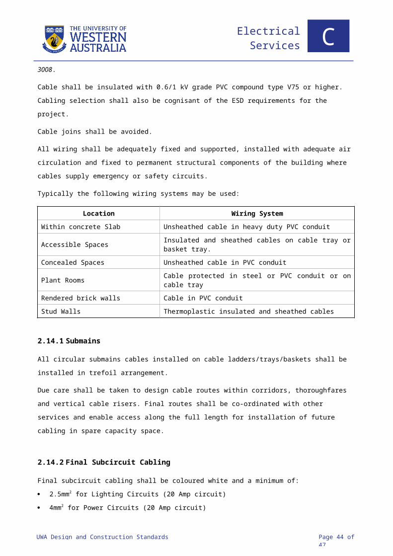
UWA Design and Construction Standards Page 44 of 47
4 Specifications
4.1 PREFERRED SUPPLIER LIST
Item Preferred Suppliers
HV Network Feeder Cable
Nexans Olex Prysmian Western Power – Equipment Stores
HV Transformer Cable Nexans Olex Prysmian
HV Switchgear Schneider ABB
HV Power Transformers
ABB Schneider Wilson
kWH (Tariff) Meters Schneider
Switchboards
Distribution Switchboard Chassis Schneider ISO Bar
Cable Ladder & Tray
LV Cable
LV Electrical Components (Switches, SSO’s etc) Clipsal 2000 Series
Lighting Control System Dynalite Organic Response
Emergency Light Monitoring System Stanlite Nexus RF
Hand Dryers Dyson
Electrical Services C

UWA Design and Construction Standards Page 45 of 47
Abbreviations
AHF Active Harmonic Filter
ANSI American National Standards Institute
ATS Automatic Transfer Switches
BMCS Building Management and Control Systems
CCTV Closed Circuit Television
CM Campus Management
DB Distribution Switchboards
DC Direct Current
DRUPS Diesel Rotary Uninterruptable Power Supply
ESD Ecologically Sustainable Design
ELV Extra Low Voltage
FSSB Fire Services Switchboard
GEC General Electric Company
GPR Ground Penetrating Radar
GPS Global Positioning System
HRC High Rupturing Capacity
HSSB Hydraulic Services Switchboard
HV High Voltage
IDMT Inverse Definite Minimum Time
IEC International Electrotechnical Commission
IEEE Institute of Electrical and Electronic Engineers
IPA Industrial Projects Australia
ISO International Organisation for Standardisation
LED Light Emitting Diode
LPG Liquified Petroleum Gas
LV Low Voltage
MDB Main Distribution Board
MEN Multiple Earth Neutral
MSB Main Switchboard
MSSB Mechanical Services Switchboard
NCC National Construction Code
PCC Point of Common Coupling
PFC Power Factor Correction
PVC Polyvinyl Chloride
RCBO Residual-current circuit breaker with overcurrent protection
RCD Residual Current Device
RFI Radio Frequency Interference
Electrical Services C

UWA Design and Construction Standards Page 46 of 47
RGB Red Green Blue
SSO Switched Socket Outlet (sometimes formerly known as GPO)
UPS Uninterruptible Power Supply System
USB Universal Serial Bus
UWA The University of Western Australia
WADCM Western Australian Distribution Connection Manual
Electrical Services C

UWA Design and Construction Standards Page 47 of 47
References
AS/NZS 1158 Lighting for roads and public spaces
AS 1319 Safety signs for the occupational environment
AS/NZS 1680 Interior Lighting
AS 1768 Lightning Protection
AS 2067 Substations and high voltage installations exceeding 1 kV a.c.
AS 2293 Emergency escape lighting and exit signs for buildings
AS 2374.1.2 Power Transformers – Minimum Energy Performance Standard requirements for
distribution transformers
AS 2676 Guide to the installation, maintenance, testing and replacement of secondary
batteries in buildings
AS/NZS 3000 Wiring Rules
AS/NZS 3008 Electrical Installations – Cable Selections
AS 3011 Installation, maintenance, testing and replacement of secondary batteries in Buildings
AS/NZS 3012 Electrical Installations – Construction and Demolition
AS/NZS 3013 Electrical installations – Classification of the fire and mechanical performance of
wiring system elements
AS/NZS 3947 Low-voltage switchgear and controlgear
AS 3953 Loading guide for dry-type power transformers
AS 4282 Control of the obtrusive effects of outdoor lighting
AS/NZS 60079 Explosive atmospheres
AS 60529 Degrees of protection provided by enclosures (IP Code)
AS/NZS 61000 Electromagnetic compatibility (EMC)
AS/NZS 61439 Low-voltage switchgear and controlgear assemblies
AS 62271 High-voltage switchgear and controlgear
AS/NZS 7000 Overhead line design
ISO 8528 Reciprocating internal combustion engine driven A.C. generating sets
National Construction Code of Australia
Electrical Services C