SWL Lifting Products Motorized Trolleys - The...
39
6:/ /LIWLQJ 3URGXFWV 0RWRUL]HG 7UROOH\V 3DUWV 2SHUDWLRQV 0DQXDO )RU 0RGHOV 07 WR 07
Transcript of SWL Lifting Products Motorized Trolleys - The...

1
SAFETY-IMPORTANTThe use of any hoist and trolley presents some risk of
personal injury or property damage.
That risk is greatly increased if proper instructions and
warnings are not followed. Before using this hoist, each
user should become thoroughly familiar with all warnings,
instructions and recommendations herein.
THIS SYMBOL POINTS OUT IMPORTANT SAFETY INSTRUCTIONS WHICH IF NOT FOLLOWED COULD ENDANGER THE PERSONAL SAFETY AND/OR PROPERTY OF YOURSELF AND OTHERS. READ AND FOLLOW ALL INSTRUCTIONS IN THIS MANUALAND ANY PROVIDED WITH THE EQUIPMENT BEFORE ATTEMPTING TO OPERATE YOUR SWL
MOTORIZED TROLLEY.

2
CONTENTS
SAFETY-IMPORTANT…………………………………………….…..…….………… 1
I. Foreword ……………………………………………………………….......……………… 3
II. Operating and Safety Procedures…..………………………………......……………… 4
III. General Information ………………………………………………………..……………. 5
IV. Installation
1. Unpacking Information…………………………………………….......……………… 6
2.Trolley to Beam.......................................................................................………… 6
3. Hoist to Trolley....................…...……………………………………………………… 7
4. Electric Installation…………………………………………………………………… 12
5.Test Running…………………………………………………………………………… 12
V. Inspection............................….………………………………………………………… 19
VI. Maintenance...……..……………………………………………………………………… 20
VII. Troubleshooting...................................................................………………………… 20
VIII. Parts List
1. Trolley Exploded view, 1~5 ton………………………………………………………… 22
2. Trolley Exploded view, 7.5 ton & 10 ton......………………………………………… 25
3. Electric Explosion, 1~10 ton.............…………………….…………………………… 27
4. Reducing Gear Motor, 0.25kw…………………………..…………………………… 29
5. Reducing Gear Motor, 0.6kw & 0.9kw…........……..………………………………… 32
6. Reducing Gear Motor, 1.5kw.........................………………………………………… 36
IX. CE Certificate of Conformity..................................................………………………… 39

3
I. FOREWORD This manual contains important information to help you properly install, operate and maintain the
�� � motor driven trolley for maximum performance, economy and safety.
Please study its contents thoroughly before putting the trolley into operation. By practicing
correct operation procedures and by carrying out the recommended preventative maintenance
suggestions, you will be assured of dependable service.
In order to help us to supply correct spare parts quickly, please always specify:
1).Trolley Model, 2). Serial Number and 3). Part Number, as well as the description.
We trust that you will find this "SWL" trolley satisfies your requirements.
Should you have any queries, please contact:
( Please ask for a company’s stamp from your local agent)

4
II. OPERATING AND SAFETY PROCEDURES The following are operating and safety procedures for safe operation of the SWL motor
driven trolley. Taking precedence over and specific rules listed here, however is the most
importance rule of all. A few minutes spent reading these rules can make an operator aware of
dangerous practices to avoid and precautions to take for his own safety and others.
1. Immediately after installation, operate trolley with safe working load over the entire length of
runway or monorail system to be sure that all adjustments and operations are satisfactory.
2. Rail stops must be installed for all trolleys operating on open end beams. These stops must
be positioned such that impact forces are absorbed by trolley side frames only.
3. When preparing to lift a load, be sure that the attachments to the hook are firmly seated in
hook saddle. Avoid off center loading on the point of hook.
4. When lifting, raise the load only enough to clear the floor or support and check to be sure
that the attachments to hook and load are firmly seated. Continue lift only after you are
assured the load is free of all obstructions.
5. When applying a load, it should be directly under the trolley. Avoid off center loading of any
kind.
6. Take up a slack load chain carefully and start lifting load slowly to avoid shock and jerking of
hoist load chain. If there is any evidence of overloading, immediately lower the load and
remove the excess load.
7. Do not allow the load to swing or twist while hoisting.
8. Anticipate the stopping point and allow trolley to coast to smooth stop. Reversing or
plugging to stop trolley causes overheating of motor and swaying of load.
9. Do not load trolley beyond the rated capacity. Overload can cause immediate failure of load
carrying parts of cause damage resulting in future failure at less than rated capacity.
10. Do not use this or any other overhead materials handling equipment for lifting or
transporting people.
11. Stand clear of all loads and avoid moving a load over the heads of other people. Warn
people of your intention to move a load in their area.

5
12. Do not leave the load suspended in the air unattached.
13. Do not wrap the load chain around the load and hook into itself as a choker chain.
Doing this will result in the follow:
(a) Operation of the upper limit switch is bypassed and the load could hit the hoist.
(b) The loss of the swivel effect of the hook which could mean twisted chain and a jammed
lift wheel.
(c) The chain could be damaged at the hook.
14. Permit only qualified personnel to operate the unit.
III. GENERAL INFORMATION The SWL motorized trolleys are designed for use with the Black Bear Electric Chain Hoists.
The trolleys are available in the following capacities: 1-Ton, 2-Ton, 3-Ton, 5-Ton, 7.5-Ton, and
10-Ton. These trolleys are similar except for the size of the load carrying members.
The trolleys have rugged steel side plates with anti-drop fins, steel wheel axles, steel suspension
bolts, construction steel load plate seated in middle of two suspension bolts for top hook of hoist
to hook on. The hot forged travelling wheels machine to suit both I-beam and flat beam.
Hardened steel gears are attached to two trackwheels and driven by a hardened steel pinion.
The pinion is driven by planetary gear reducer in high quality grease. A weather proof motor drive
the gear reducer.
The electric housing contains a reversing contactor and a terminal boards. The transformer will
be an option depending on the user's need. The 3-phase motor is always equipped with a
magnetic brake over the end of driven motor. Above the housing bottom, there three holes, one
for cord from hoist, another for control cord from hoist, the third one for trolley motor cord, it will
serve as an option for equipped with the Push-Bottom-Station cord for the trolley. In addition,
there are two option holes on each side of the housing, motor power cord on the right, and an
optional hole for the power cord to trolley on the left. All five holes are equipped with cable gland
for IP-54 protection optionally. Please refer to Illust: 5 on page 13.
6
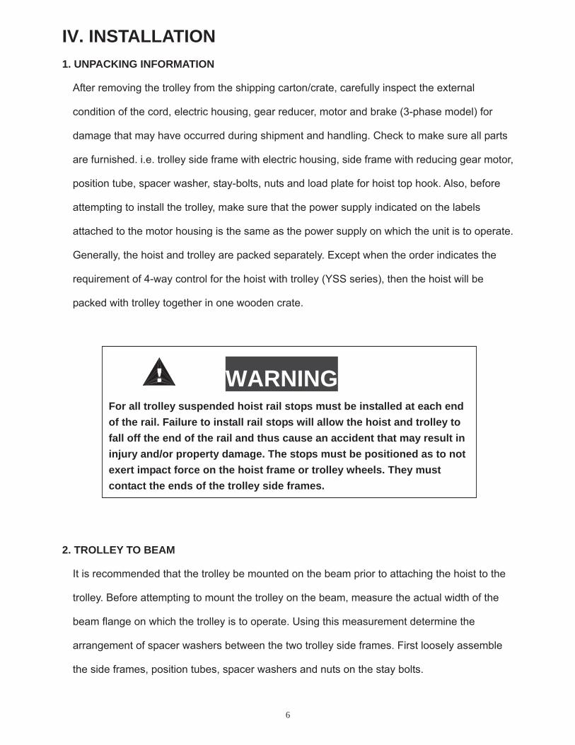
IV. INSTALLATION 1. UNPACKING INFORMATION
After removing the trolley from the shipping carton/crate, carefully inspect the external
condition of the cord, electric housing, gear reducer, motor and brake (3-phase model) for
damage that may have occurred during shipment and handling. Check to make sure all parts
are furnished. i.e. trolley side frame with electric housing, side frame with reducing gear motor,
position tube, spacer washer, stay-bolts, nuts and load plate for hoist top hook. Also, before
attempting to install the trolley, make sure that the power supply indicated on the labels
attached to the motor housing is the same as the power supply on which the unit is to operate.
Generally, the hoist and trolley are packed separately. Except when the order indicates the
requirement of 4-way control for the hoist with trolley (YSS series), then the hoist will be
packed with trolley together in one wooden crate.
2. TROLLEY TO BEAM
It is recommended that the trolley be mounted on the beam prior to attaching the hoist to the
trolley. Before attempting to mount the trolley on the beam, measure the actual width of the
beam flange on which the trolley is to operate. Using this measurement determine the
arrangement of spacer washers between the two trolley side frames. First loosely assemble
the side frames, position tubes, spacer washers and nuts on the stay bolts.
WARNINGFor all trolley suspended hoist rail stops must be installed at each end of the rail. Failure to install rail stops will allow the hoist and trolley to fall off the end of the rail and thus cause an accident that may result in injury and/or property damage. The stops must be positioned as to not exert impact force on the hoist frame or trolley wheels. They must contact the ends of the trolley side frames.
7
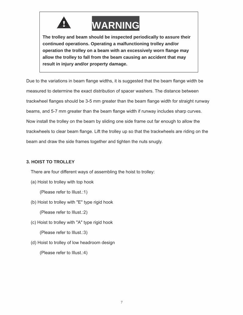
Due to the variations in beam flange widths, it is suggested that the beam flange width be
measured to determine the exact distribution of spacer washers. The distance between
trackwheel flanges should be 3-5 mm greater than the beam flange width for straight runway
beams, and 5-7 mm greater than the beam flange width if runway includes sharp curves.
Now install the trolley on the beam by sliding one side frame out far enough to allow the
trackwheels to clear beam flange. Lift the trolley up so that the trackwheels are riding on the
beam and draw the side frames together and tighten the nuts snugly.
3. HOIST TO TROLLEY
There are four different ways of assembling the hoist to trolley:
(a) Hoist to trolley with top hook
(Please refer to Illust.:1)
(b) Hoist to trolley with "E" type rigid hook
(Please refer to Illust.:2)
(c) Hoist to trolley with "A" type rigid hook
(Please refer to Illust.:3)
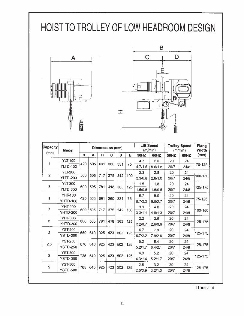
(d) Hoist to trolley of low headroom design
(Please refer to Illust.:4)
WARNINGThe trolley and beam should be inspected periodically to assure their continued operations. Operating a malfunctioning trolley and/or operation the trolley on a beam with an excessively worn flange may allow the trolley to fall from the beam causing an accident that may result in injury and/or property damage.

8

9

10
11
12
4. ELECTRICAL INSTALLATION
The trolley electrical connection must be completed as shown in Illust.5, the Hoist & Trolley
General Arrangement. Generally, the electric housing is provided with three holes in the bottom,
one for trolley motor cord, the second one for trolley power cord from hoist and the third one for
control cord from hoist. Moreover, the optional five holes design for independent usage of trolley
are also available, please refer to the Illus.5. There are two holes on each side of the housing, on
the left is the power cord for trolley, on the right is for the trolley motor cord.
For the details of wiring connection, please refer to the wiring diagrams (Illust.6 & 7). Also be
noted that the above mentioned diagrams only acceptable for the standard units of 3-phase &
1-phase.
Hoist with trolley wiring diagram shown example as follows:
Illust.8 is 3 phases, single speed model.
Illust.9 is 3 phases, dual speed model.
Illust.10 is 3 phases, hoist dual speed, trolley single speed model.
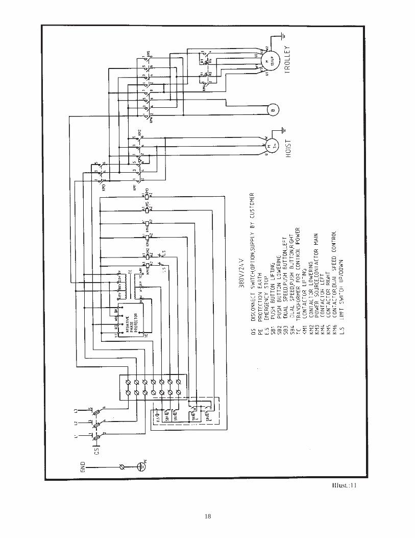
Illust.11 is 3 phases, hoist single speed, trolley dual speed model.
For special unit, please see wiring diagram supplied with unit.
5. TEST RUNNING
After trolley to beam, hoist hook to trolley and wiring connection completed, operate the trolley
forward and backward over a short distance. Then you can operate the trolley over the entire
length of runway or monorail system to be sure that all adjustment and operations are
satisfactory.
WARNINGPower should be disconnected when making or changing connections, also proper grounding should be accomplished.

13

14

15

16

17
18

19
V. INSPECTION To maintain continuous and satisfactory operation, a regular periodic inspection procedure must
be initiated so that worn or damaged parts can be replaced before they become unsafe. The
frequency of inspection must be determined by the individual application.
The following list gives an inspection procedure for normal usage under normal conditions. When
the unit is subjected to heavy usage or duty, moist or other adverse atmospheric conditions,
shorter time periods must be assigned. Inspection must be made of all parts for unusual wear,
corrosion or damage in addition to those specifically mentioned in the succeeding list.
It is suggested that the unit be inspected monthly for wear damage and corrosion effects to all
parts with particular attention to the following:
1. Tightness of all fasteners.
2. Contactor and control station for burnt or pitted contacts and loose or corroded terminals.
3. Cables and leads for broken wires, loose or corroded terminals and damaged insulation.
4. Terminal board for loose or corroded connections.
5. Trackwheels for wear of tread, flange and bearings.
6. Gear portion of trackwheel and pinion for wear.
7. Check the wear of top hook to load plate in trolley. If type "E" & "A" rigid hook are used,
check he condition of those parts.
8. Collector or power supply system for damage, wear corrosion and proper operation.
9. 3-phase trolley is usually equipped with motor brake. Check the wear of brake lining and
adjusting the gap between lining and drum to assure brake efficiency.
20
VI. MAINTENANCE The following three steps are recommended for maintenance:
1. Once a month lubricate track wheel gear and pinion with grease or graphite grease.
2. Motor reducing gearbox uses planetary gear lubricated with cosmo No. 3 grease (Equivalent
to: Shell Unedo 3, Exxon Eastan 3, Mobil Cup Grease 3) for good maintenance. It is highly
recommended that the motor gearbox grease should be changed after 100 hours of operation,
then every 6 months or 2500 hours of normal service. Whichever comes first, the grease
needs to be changed as well.
3. The motor brake should be changed & be checked periodically for wear of brake lining and
disc. The gap between brake lining & disc can be adjusted by the brake adjusting hex. bolts
over the end of motor. (Please refer to the parts list on page 32 No.28 and page 36 No. 19 ,
brake adjusting hex. bolt.)
VII. TROUBLE SHOOTING Please refer to table 1 on page 21.
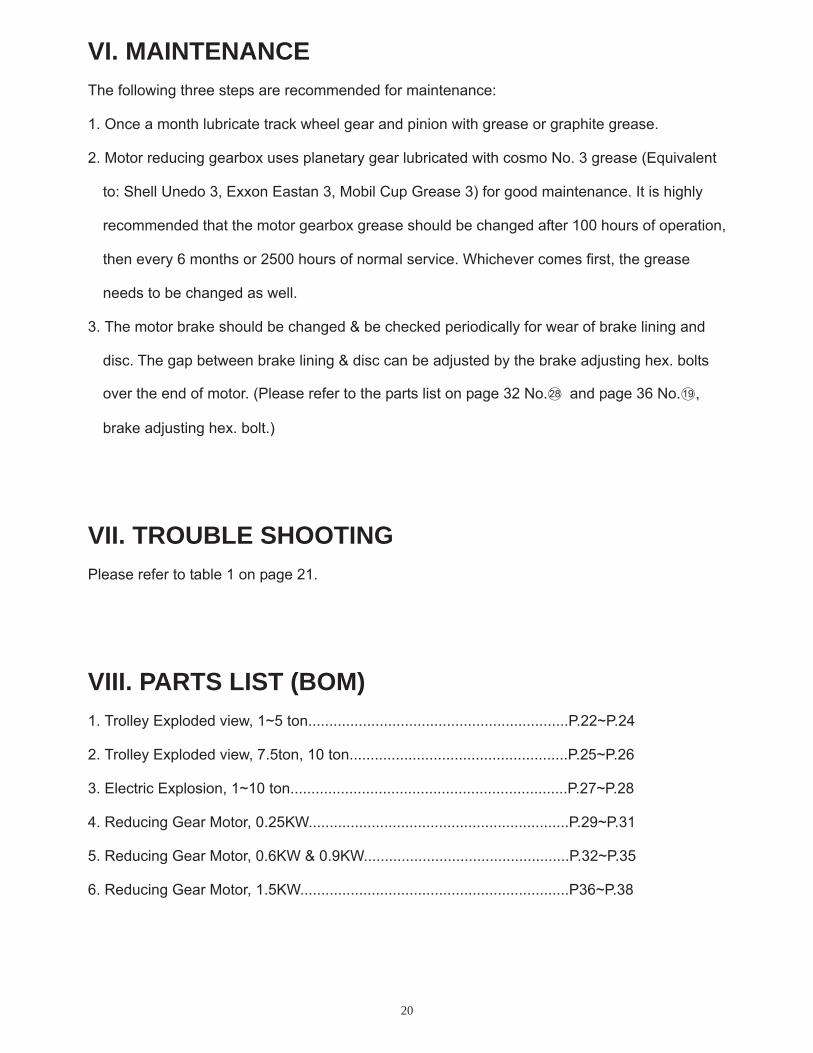
VIII. PARTS LIST (BOM) 1. Trolley Exploded view, 1~5 ton..............................................................P.22~P.24
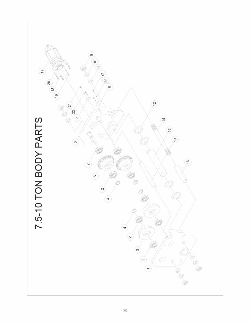
2. Trolley Exploded view, 7.5ton, 10 ton....................................................P.25~P.26
3. Electric Explosion, 1~10 ton..................................................................P.27~P.28
4. Reducing Gear Motor, 0.25KW..............................................................P.29~P.31
5. Reducing Gear Motor, 0.6KW & 0.9KW.................................................P.32~P.35
6. Reducing Gear Motor, 1.5KW................................................................P36~P.38

21
Table 1. Troubleshooting and Remedial Action IF
1.Trolley does not operate in either direction.
2.Trolley operates in one direction only.
3.Trolley operates sluggishly
4.Motor overheats
CAUSE MAY BE a) Power failure at trolley
b) Phase error (Single phasing)
c) Turn on control circuit
d) Wrong voltage or frequency
e) Low voltage
f) Excessive load
a) Turn on control circuit
a) Excessive load b) Low Voltage c) Worn or dirty rail
a) Excessive load b) Low voltage c) Extreme external heating
d) Frequent starting or reversing
e) Phase error
REMEDYMain line or branch circuit switch power on, branch line fuse blown or circuit breaker tripped.Power off, replace or reset. Check for grounded or connect supply lines or current collectors.
Power on, grounded or connected one line of supply system, collectors, trolley wiring, reversing contactor, motor leads or windings. Check for electrical continuity.
Power on or shorted windings in transformer or reversing contactor coil, loosen connection or broken wire in circuit, mechanical binding in contactor, control station switch contacts not making. Check continuity and repair or replace defective parts.
The voltage and frequency must be the same as shown on trolley control box.
Control power supply deviates from standard not to exceed 10% to prevent abnormal operation or damage to the motor.
Prevent frequently loading rated load of trolley.
As item 1. c)
As item 1. f) As item 1. e) Clean rails, inspect for worn spots.
As item 1. f) As item 1. e) Above an ambient temperature of 40 ., the frequency of trolley operation must be limited to avoid overheating of motor. Special provision should be made to ventilate the space or shield the trolley from heat radiation.
Excessive inching, jogging or plugging should be avoided since this type of operation will drastically shorten the life of motor and contactor.
As item 1. e)

22
1 6
15
13
14
1-5
T ON
BOD
YP
AR
TS
21
3
10
4
12
1 1
6
5
78
9

23
BODY PARTS B.O.M. Q’TY REQ’D EACH UNIT
NO.PARTS CODE
DESCRIPTION1T 2T 3T 5T
202961 1 202962 1202963 1
1
202964
Electric Frame
1 407835 Bearing <6204 Z> 8 407830 Bearing <6205 Z> 8 407824 Bearing <6206 Z> 8
2
407808 Bearing <6207 Z> 8 203131 Plain Wheel<ø105 40L> 2 203132 Plain Wheel<ø119 49L> 2 203133 Plain Wheel<ø133 54L> 2
3
203134 Plain Wheel<ø143.5 59L> 2 400191 Retaining Ring<S-20> 4 400192 Retaining Ring<S-25> 4 400193 Retaining Ring<S-30> 4
4
400194 Retaining Ring<S-35> 4 203111 Gear Wheel<M3.5 28T 47L> 2 203112 Gear Wheel<M3.5 32T 56L> 2 203113 Gear Wheel<M3.5 36T 59L> 2
5
203114 Gear Wheel<M3.5 39T 67L> 2 202931 1 202932 1202933 1
6
202934
Motor Frame
1 203221 Spacer Washer<ø40 ø24 1/8”> 32 203222 Spacer Washer<ø46 ø27 1/8”> 32 203223 Spacer Washer<ø54 ø34 1/8”> 32
7
203224 Spacer Washer<ø60 ø40 1/8”> 32 400102 Spring Washer<7/8”> 4 400103 Spring Washer<1”> 4 400105 Spring Washer<1 1/4”> 4
8
400106 Spring Washer<1 1/2”> 4 400070 Hex. Nut<7/8” 9UNC> 4 400071 Hex. Nut<1” 8UNC> 4 400072 Hex. Nut<1 1/4” 7UNC> 4
9
400073 Hex. Nut<1 1/2” 6UNC> 4

24
BODY PARTS B.O.M. Q’TY REQ’D EACH UNIT
NO.PARTS CODE
DESCRIPTION1T 2T 3T 5T
400057 Stay Bolt<7/8” 9UNC 250L> 2 400059 Stay Bolt<1” 8UNC 290L> 2 400063 Stay Bolt<1 1/4” 7UNC 360L> 2
10
400066 Stay Bolt<1 1/2” 6UNC 365L> 2 203151 Position Tube<ø34 ø24 56L> 4 203152 Position Tube<ø38 ø28 69L> 4 11 203153 Position Tube<ø50 ø40 83.5L> 4 4 203186 Load Bracket<t13 102 175L> 1 203187 Load Bracket<t13 115 180L> 1 203188 Load Bracket<t16 120 230L> 1
12
203189 Load Bracket<t19 135 260L> 1 201761 Transmission Pinion<0.25Kw-M3.5 16T> 1 1
13201771 Transmission Pinion<0.6Kw-M3.5 16T> 1 1
Motor Ass’y-0.25Kw 1 1 14
Motor Ass’y-0.6Kw 1 1 15 400096 Spring Washer<M10> 4 4 4 4
400045 Hex. Headed Bolt<M10 1.5 20L> 4 400046 Hex. Headed Bolt<M10 1.5 25L> 4 16400047 Hex. Headed Bolt<M10 1.5 30L> 4 4
25
7.5 -
10TO
NBO
DY
PAR
T S
21
3
2
13
16
15
12
2
2
2221
10
2122
11
1918
20
1 7
4
5
67
4
9
8
14

26
BODY PARTS B.O.M. Q’TY REQ’D EACH UNIT
NO.PARTS CODE
DESCRIPTION7.5T 10T
202965 1 1
202966Electric Frame
1 407817 Bearing<6307 Z> 8
2407825 Bearing<6308 Z> 8 203135 Plain Wheel<ø178.5 60L> 2
3203136 Plain Wheel<ø203 60L> 2 400194 Retaining Ring<S-35> 4
4400195 Retaining Ring<S-40> 4 203115 Gear Wheel<M3.5 49T 65L> 2
5203116 Gear Wheel<M3.5 56T 65L> 2 202935 1
6202936
Motor Frame 1
7 200636 Stopper For Load Shaft<t6 25 50L> 1 1 8 200635 Stopper For Load Shaft<t6 38 70L> 1 1
400073 Hex. Nut<1 1/2” 6UNC> 49
400644 Hex. Nut<1 3/4” 5UNC> 4 400106 Spring Washer<1 1/2”> 4
10400104 Spring Washer<1 3/4”> 4 203171 Spacer Sleeve<ø50 ø40 13L> 8
11 203172 Spacer Sleeve<ø60 ø46 13L> 8
12 203225 Spacer Ring<ø100 ø71 13L> 4 4 203208 Load Shaft B<ø38 320L> 1
13203209 Load Shaft B<ø38 340L> 1 400407 Stay Bolt<1 1/2” 6UNC 430L> 2
14400411 Stay Bolt<1 3/4” 5UNC 460L> 2 203203 Load Shaft A<ø70 340L> 1
15203204 Load Shaft A<ø70 360L> 1 203155 Stay Bolt Position Tube<ø50 ø40 216L> 2
16203156 Stay Bolt Position Tube<ø60 ø46 216L> 2
Motor Ass’y-0.9Kw 1 17
Motor Ass’y-1.5Kw 1 18 400096 Spring Washer<M10> 4 4 19 400047 Hex. Headed Bolt<M10 1.5 30L> 4 4
201782 Transmission Pinion<0.9Kw-M3.5 16T> 120
201730 Transmission Pinion<1.5Kw-M3.5 23T> 1 21 400012 Hex. Recess Bolt<M8 1.25 20L> 4 4 22 400095 Spring Washer<M8> 4 4

27
ELE
CT R
ICE
XPL
OS
ION
5
63
10
1 1
12
142
41
913
12
US
A10
14
15

28
ELECTRIC PARTS B.O.M. Q’TY REQ’D EACH
UNITNO. PARTS CODE DESCRIPTION
STD USA
1 400006 Hex. Recess Bolt<M6×1.0×16L> 6 6
2 400094 Spring Washer<M6> 6 6
300316 Electric Housing 1 3
300305 Electric Housing<USA> 1 300348 Electric Housing Cover 1 4300349 Electric Housing Cover<USA> 1
5 Contactor 2 2
6 400211 Spring Pin<ø3×14L> 1 1
7 400266 Rubber Band 1 1
8 402515 Gasket 15# 1 1
9 300079 Contactor Rail<2PC> 1 1
400270 Rubber Cap 2 10400222 Rubber Cap<USA> 2
11 402516 Gasket 16# 1 1
12 400052 Cross Headed Screw<M4×0.7×15L> 4 4
13 400092 Spring Washer<M4> 4 4
400339 Rubber Cap 1 14
400222 Rubber Cap<USA> 1
15 400941 Rubber Cap<USA> 2

29
23
4
0 .25
kwR
ED
UC
I NG
GE
AR
MO
T OR
1
5
6
15
1 213
7
11
98
10
14
3-PH
ASE
1-PH
ASE
1617
19
2122
2324
2 9
2 526
2728
18
5
2 0
19
30
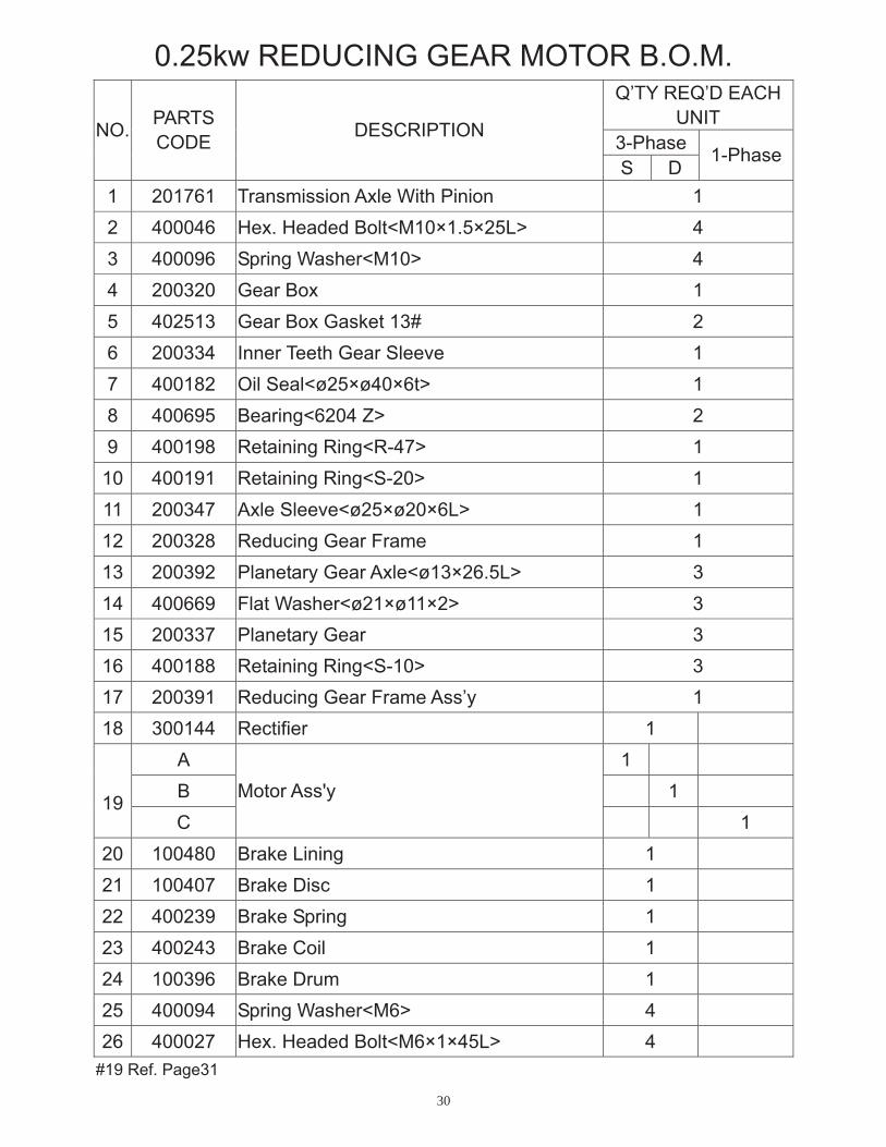
0.25kw REDUCING GEAR MOTOR B.O.M. Q’TY REQ’D EACH
UNIT3-PhaseNO. PARTS
CODE DESCRIPTION
S D 1-Phase
1 201761 Transmission Axle With Pinion 12 400046 Hex. Headed Bolt<M10×1.5×25L> 43 400096 Spring Washer<M10> 44 200320 Gear Box 15 402513 Gear Box Gasket 13# 26 200334 Inner Teeth Gear Sleeve 17 400182 Oil Seal<ø25×ø40×6t> 18 400695 Bearing<6204 Z> 29 400198 Retaining Ring<R-47> 1
10 400191 Retaining Ring<S-20> 111 200347 Axle Sleeve<ø25×ø20×6L> 112 200328 Reducing Gear Frame 113 200392 Planetary Gear Axle<ø13×26.5L> 314 400669 Flat Washer<ø21×ø11×2> 315 200337 Planetary Gear 316 400188 Retaining Ring<S-10> 317 200391 Reducing Gear Frame Ass’y 118 300144 Rectifier 1
A 1 B 119C
Motor Ass'y 1
20 100480 Brake Lining 1 21 100407 Brake Disc 1 22 400239 Brake Spring 1 23 400243 Brake Coil 1 24 100396 Brake Drum 1 25 400094 Spring Washer<M6> 4 26 400027 Hex. Headed Bolt<M6×1×45L> 4
#19 Ref. Page31

31
0.25kw REDUCING GEAR MOTOR B.O.M. Q’TY REQ’D EACH
UNIT3-PhaseNO. PARTS
CODE DESCRIPTION
S D 1-Phase
27 400084 Nut<M12×1.75> 1
28 400030 Hex. Headed Bolt<M12×1.75×30L> 1
29 100502 Brake Drum Ass’y 1
NO. PARTS CODE DESCRIPTION -HZ-V 106520 220V/380V 106521 220V/440V 106511 230V/460V 106499 240V 106500 480V 106525
3 60HZ
600V106501 220V/380V 106503 400V 106504 415V
A
106506
Motor Ass'y (S)
3 50HZ
525V106816 208V 106807 220V 106441 230V 106809 380V 106810 440V 106811 460V 106813
3 60HZ
600V106800 220V 106444 230V 106802 380V 106443 400V 106804 415V
B
106805
Motor Ass'y (D)
3 50HZ
525V106751 110V/220V 106750
1 60HZ115V/230V
106743 110V/220V
19
C
106744
Motor Ass'y 1 50HZ
220V/230V

32
0.6
k w/0
.9kw
RE
DU
CIN
GG
EA
RM
OT O
R
4
5
12
2021
2223
24
2 9
2526
2728
3-PH
ASE
1819
19
1-PH
ASE
1617
171 6 3
11
6
78
7
91 0
151 2
1314

33
0.6kw/0.9kw REDUCING GEAR MOTOR B.O.M. 0.6kw 0.9kw
3-Phase 3-Phase NO. PARTS CODE DESCRIPTION
S D S D 1-Phas
e
201771 1 1201782
Transmission Axle With Pinion 1
2 200319 Gear Box 13 402519 Gear Box Gasket B 14 200336 Inner Teeth Gear Sleeve 15 402517 Gear Box Gasket A 16 400939 Oil Seal<30×45×8> 17 400803 Bearing<6205Z> 28 400199 Retaining Ring<R-52> 19 200332 Reducing Gear Frame 1
10 200394 Planetary Gear Axle<ø15×29.5L> 311 400192 Retaining Ring<S-25> 112 400667 Flat Washer<ø20×ø12×2> 313 200342 Planetary Gear 314 400189 Retaining<S-12> 315 200326 Reducing Gear Frame Ass’y 116 400095 Spring Washer<M8> 417 400426 Hex. Recess Bolt<M8×1.25×45L> 418 300144 Rectifier 1
A 1 1B 1 119C
Motor Ass’y 1
20 100401 Brake Lining 121 100402 Brake Disc 122 400314 Brake Spring 123 400244 Brake Coil 124 100403 Brake Drum 125 400094 Spring Washer<M6> 4
#19Ref. Page34

34
0.6kw/0.9kw REDUCING GEAR MOTOR B.O.M. 0.6kw 0.9kw
3-Phase 3-Phase NO. PARTS CODE DESCRIPTION
S D S D 1-Phas
e
26 400027 Hex. Headed Bolt<M6×1×45L> 427 400085 Nut<M16×1.5> 128 400468 Hex. Headed Bolt<M16×1.5×50L> 129 100501 Brake Drum Ass’y 1
NO. PARTS CODE DESCRIPTION -HZ-V 106600 220V/380V 106601 220V/440V 106610 230V/460V 106605
3 60HZ
600V106581 220V/380V 106597 400V 106584 415V 106585 440V 106586
0.6KW
3 50HZ
525V106680 220V/380V 106681 220V/440V 106688 230V/460V 106685
3 60HZ
600V106661 220V/380V 106662 400V 106664 415V 106665 440V 106666 525V
A
106700
Motor Ass'y (S)
0.9KW
3 50HZ
550V106836 208V 106837 220V 106830 230V 106839 380V 106840 440V 106841 460V 106843
3 60HZ
600V
19
B
106832
Motor Ass'y (D) 0.6KW
3 50HZ 380V

35
0.6kw/0.9kw REDUCING GEAR MOTOR B.O.M.NO. PARTS CODE DESCRIPTION -HZ-V
106846 400V 106834 415V 106799 440V 106842 460V 106835
0.6KW 3 50HZ
525V106867 220V 106869 380V 106871 460V 106859
3 60HZ
600V106862 380V 106863 400V 106864 415V
B
106865
Motor Ass'y (D)
0.9KW
3 50HZ
525V106787 110V/220V 106786
1 60HZ115V
19
C106783
Motor Ass'y 0.9KW1 50HZ 110V/220V
36
1 .5
k wR
ED
UC
ING
GE
AR
MO
TOR
67
12
3
89
5
26
4
2524
2322
2120
1 0
1112
2732
1314
2 916
17
1819
1 5
2 8
3031

37
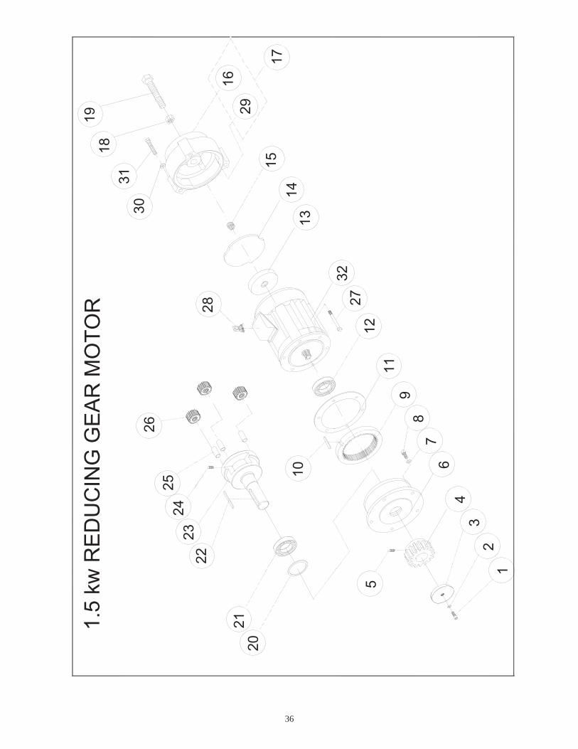
1.5kw REDUCING GEAR MOTOR B.O.M. Q’TY REQ’D EACH
UNIT3-PhaseNO. PARTS
CODE DESCRIPTION
S D
1 400013 Hex. Recess Bolt<M8×1.25×25L> 12 400095 Spring Washer<M8> 13 200349 Pinion’s End Stopper 14 201730 Transmission Axle Pinion 15 400204 Bolt<M8×1.25×12L> 16 200323 Gear Box 17 400095 Spring Washer<M8> 68 400013 Hex. Recess Bolt<M8×12.5×25L> 69 200335 Inner Teeth Gear Sleeve 1
10 400951 Key<t7×7×50L> 111 402514 Motor Gasket 14# 112 400124 Bearing<6907> 113 100482 Brake Lining 114 100459 Brake Disc 115 400314 Brake Spring 116 100458 Brake Drum 117 100503 Brake Drum Ass’y 118 400085 Nut<M16×1.5> 119 400468 Hex. Recess Bolt<M16×1.5×50L> 120 400187 Oil Seal<35×50×8> 121 400145 Bearing<6207 Z> 122 400980 Key<t10×10×70L> 123 200331 Reducing Gear Frame 124 400205 Bolt<M5×0.8×8L> 325 200346 Planetary Gear Axle 326 200339 Planetary Gear 327 400013 Hex. Recess Bolt<M8×1.25×25L> 6

38
1.5kw REDUCING GEAR MOTOR B.O.M. Q’TY REQ’D EACH
UNIT3-PhaseNO. PARTS
CODE DESCRIPTION
S D
28 300144 Rectifier 129 400245 Brake Coil 130 400095 Spring Washer<M8> 331 400012 Hex. Recess Bolt<M8×1.25×20L> 3
A 1 32
BMotor Ass’y
1
NO. PARTS CODE DESCRIPTION -HZ-V 106726 220V/380V 106727 220V/440V 106729
3 60HZ460V
106701 220V/380V 106702 400V 106704 415V
A
106705
Motor Ass'y (S)
3 50HZ
550V106882 220V 106884 380V 106886
3 60HZ460V
106877 380V 106878 400V
32
B
106879
Motor Ass'y (D)
3 50HZ415V