Introduction to Telecommunication Network An exchange of standard code information between devices...
21
www.telkomuniversity.ac.id Fathur AB Anin A Afif A Hari A Gary A Dhika AB April AB Mulya AB Rizka B Dion AB Siska AB Mirel AB Hani AB Airita AB Yusuf AB
Transcript of Introduction to Telecommunication Network An exchange of standard code information between devices...

www.telkomuniversity.ac.id
Fathur AB
Anin A
Afif A
Hari A
Gary A
Dhika AB
April AB
Mulya AB
Rizka B
Dion AB
Siska AB
Mirel AB
Hani AB
Airita AB
Yusuf AB
www.telkomuniversity.ac.id
Signaling
Course Number : TTH2A3
CLO : 1
Week : 4 (end of CLO #1)

www.telkomuniversity.ac.id
Call Establishment
Two types of signaling:
• CAS (Channel Associated Signaling)
• CCS (Common Channel Signaling)
Seizure(off-hook)
Ringing
tone
Ringing
current
Backward clear (on-hook)
Dial tone
Address digit(B-number)
Answer(off-hook)
Forward clear
(on-hook)
- Identification of calling subscriber
- Allocation of storage
address digits and
- Connection of common
equipment
- Disconnection of
dialtone
- Digit analysis and
search of B sub
- Switch path set
- Disconnection of
equipment
EXCHANGE
C O N V E R S A T I O N
Supervision
111012
BA
12
3
4
6
7a 7b
8
5
9
Cal
l set
up
C
all s
etu
p
Clear down Clear down

www.telkomuniversity.ac.id
What is Signaling?
• An exchange of standard code information between devices in the network
• Functionalities: – Call setup
– Supervision
– Clear down
A(calling party)
B(called party)
release
signal
release signal
A(calling party)
c) clear down
Telecom
Network
release signal
release
signal
B(called party)
b) conversation
Telecom
Network
speech
speech
speech
A(calling party)
B(called party)
setup
signal
setup signal
a) call setup
Telecom
Network
setup signal
setup
signal
speech path
signaling path
node (exchange)
www.telkomuniversity.ac.id
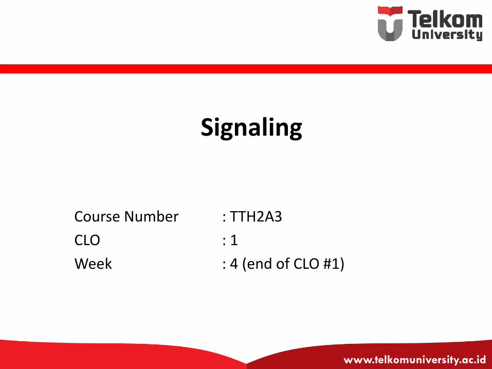
Signaling Classification (1/4)
1. Based on transmission channel – CAS (Channel Associated Signaling), signaling = information
– CCS (Common Channel Signaling), one channel for all signaling
2. Based on functionalities – Line signaling
– Register signaling
• decadic pulse
• MFC
– Non compelled
– Compelled
» Full MFC
» Semi MFC
on-hook off-hook
dial " 3"
IDT
dial " 1"
t (ms)
Vab

www.telkomuniversity.ac.id
Signaling Classification (2/4)
3. Based on delivery method
– End to end
– Link by link
– Enblock
– Overlap
4. Based on direction to establish a call
– Forward
– Backward

www.telkomuniversity.ac.id
Signaling Classification (3/4)
5. Based on current characteristic
– Direct Current
– Alternating Current • Number of frequency used (single and multi frequency)
• Frequency used compared to bandwidth (in-band and out of-band)
– Analog
– Digital
6. Based on direction to establish a call
– Forward
– Backward

www.telkomuniversity.ac.id
Signaling Classification (4/4)
7. Based on network segment
– Subscriber segment • Z interface (analog)
• Digital Subscriber System (DSS) #1 (digital)
– Inter-Exchange segment
8. Based on geographical
– Regional
– International

www.telkomuniversity.ac.id
Illustration
Local
Exchange
MDF
Secondary
Cable
Distribution
Point
NTE
Telephone
Demarcation
Point
Primary
Cable
Street
Cabinet
Dro
p
wire
Telecom
Network
subscriber
signaling
Inter-exchange signaling
subscriber signaling
Subscriber lines
(Access Network)
Network signaling
(inter-exchange signaling)
Subscriber
signaling
Subscriber
signaling

www.telkomuniversity.ac.id
Line and Register Signaling
• Line signal is for supervisory: – monitor: idle, blocking, etc.
– control: clear forward, force release, seizure, etc.
• Register signal carries information about phone number (source/calling and destination/called), source class, destination status (idle/busy): – Decadic pulses
– MFC (Multi Frequency Code) contains 2 to 6 frequency for each code
on-hook off-hook
dial " 3"
IDT
dial " 1"
t (ms)
Vab

www.telkomuniversity.ac.id
CAS and CCS
• CAS: every information channel equally associated with signaling channel. The channel physically could be the same or different (separated in time or frequency)
• CCS: several information channels use common channel for signaling. Usually physically separated. Example of CCS is SS7 (Signaling System Number 7)
1
2
n
Exchange BExchange A
signaling channelvoice/data channel
signaling channelvoice/data channel
n voice/data channel
1
2
nExchange A Exchange B
m
m << n1
m signaling channel

www.telkomuniversity.ac.id
Signaling System 7
History
• Signaling System 1 to 5 use in-band signaling (CAS)
• CCITT developed a digital signaling standard called Signaling System 6
• SS6 was based on Packet-Switched, proprietary data network
• SS6 uses 2.4 kbps data links to send packets of data to distant switches to request service
• SS7 began deployment in 1983, was initially used for inter office network, but now it is deployed in local central offices
• Provides a global standard for call setup, routing, control and database access
CCSS7 CCSS7
N7 N7
CCIS7 CCIS7

www.telkomuniversity.ac.id
Signaling System 7
Elements
SP (Signaling Point)
• STP (Signaling Transfer Point)
• SCP (Signaling Control Point)
• SSP (Service Switching Point)
• SEP (Signaling End Point)
SL (Signaling Link)
• A Link
• B Link
• C Link
• D Link
• E Link

www.telkomuniversity.ac.id
Signalling Point (SP)
• SP is any node in the network that can process signaling message
• SEP (Signaling End Point) or simply SP is a SP that can only process signaling message dedicated to it
• On the contrary, STP (Signaling Transfer Point) can transfer signaling message to other SP
• Example: 1. Local Exchange / Central Office (Switching Center)
2. Operation and Maintenance Center (OMC)
3. Service Control Point (SCP)
4. Signaling Transfer Point (STP)

www.telkomuniversity.ac.id
Signaling Link between SP and STP
• Signaling Link (SL) – Transmission media to transfer signaling message between two SP
• Link Set – Bundle of SL that connect two SP directly
• Link Group – Several SL within Link Set that has similar characteristic
link group
link set signalling link
link group
SP STP

www.telkomuniversity.ac.id
Signaling Route
• Originating Point, SP that originally sends a signaling message
• Destination Point, SP that the signaling message is intended to receive
• Signaling Route, is the path designated to deliver the signaling message
• Signaling Route consists of STP and SL, which reside between Originating Point (OP) and Destination Point (DP)

www.telkomuniversity.ac.id
Signaling Mode
Based on the link used to deliver information and signaling, signaling mode is distinguished into:
1. Associated
2. Non Associated
Quasi Associated, predefined route
Fully Non Associated, free route (not applicable due to incapability to reconstruct message)
SP SP
Associated
Signaling
Speech
SP SP
STP STP
SP SP
STP
STP
STP
STP
www.telkomuniversity.ac.id
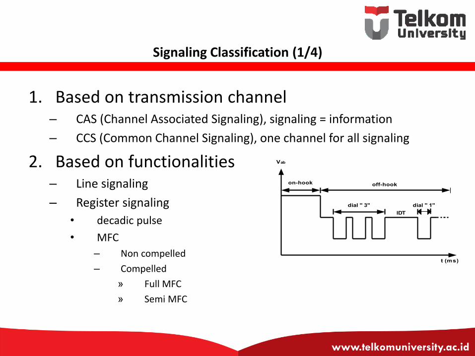
Information Plane & Control Plane
• In SS7, signalling message provides call management (call setup, supervision, termination) and network management
• Signalling message are sent as short message block (packet) using message switching between SP and STP
• There will be two network plane: – Information plane (deliver information using circuit switch)
– Control plane (deliver signaling using message switch)

www.telkomuniversity.ac.id
Control Plane
STP
User
STP
STP STP
User
SP
SP
CONTROL PLANE
SP = Signalling Point STP = Signalling Transfer Point
SP
SP
SP
SP
SP
SS7

www.telkomuniversity.ac.id
Information Plane
User User
LE
LE
INFORMATION PLANE
LE = Local Exchange TC = Transit Center
TC
TC

www.telkomuniversity.ac.id
End of CLO #1 See you on next class