Introduction to Engineering Drawings By: Chris Vandelaar University Machine Services TEB Rm. 50...
61
Introduction to Engineering Drawings By: Chris Vandelaar University Machine Services TEB Rm. 50 Resources: Doug Phillips – Previous MME259A presentation Interpreting Engineering Drawings 3 rd edition by Jensen & Hines
-
Upload
michael-nichols -
Category
Documents
-
view
216 -
download
0
Transcript of Introduction to Engineering Drawings By: Chris Vandelaar University Machine Services TEB Rm. 50...
Introduction to Engineering Drawings
By: Chris VandelaarUniversity Machine Services
TEB Rm. 50
Resources: Doug Phillips – Previous MME259A presentation Interpreting Engineering Drawings 3rd edition by Jensen & Hines
Engineering Drawings:The language of manufacturing
How we communicate our intentions as designers
Convey all necessary information to get things made, manufactured, modified, assembled
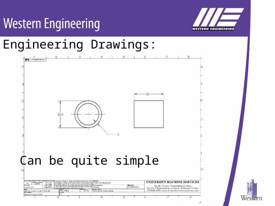
Engineering Drawings:
Can be quite simple
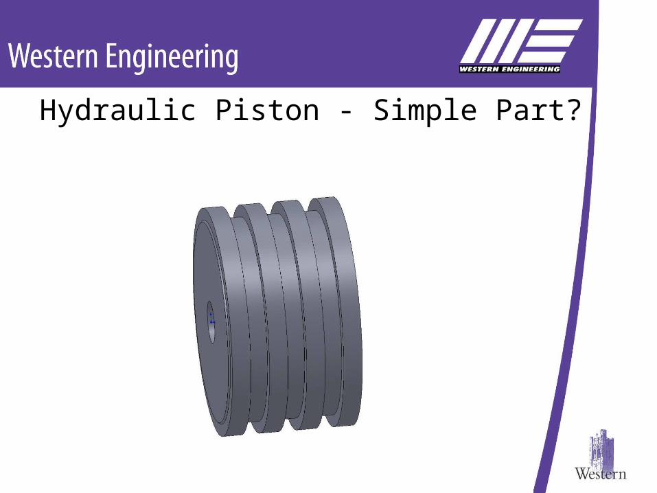
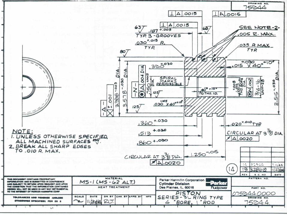
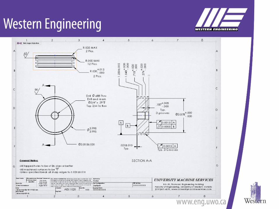
Hydraulic Piston - Simple Part?
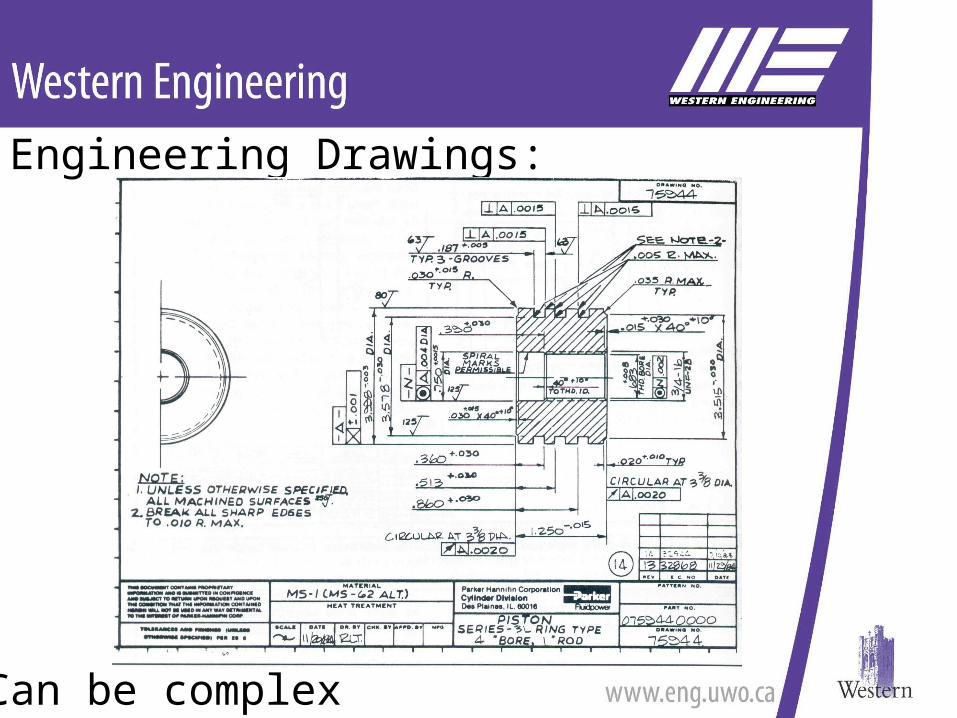
Engineering Drawings:
Can be complex
Engineering Drawings:Contain only pertinent information
To ensure all engineering specifications and requirements are met
What is pertinent
• Form – shape of the part• Geometry – acceptable deviation from form• Dimensions – sizes of forms and shapes• Tolerances – acceptable deviation from
dimensions• Surface finish and or treatment• Other General information - notes
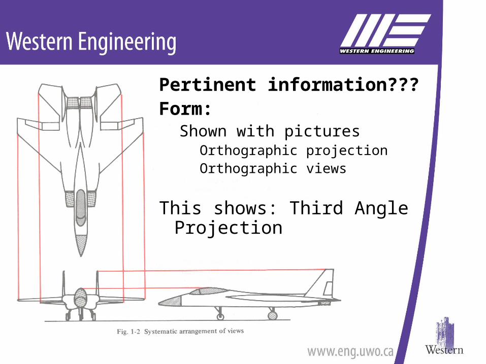
Pertinent information???Form:
Shown with picturesOrthographic projectionOrthographic views
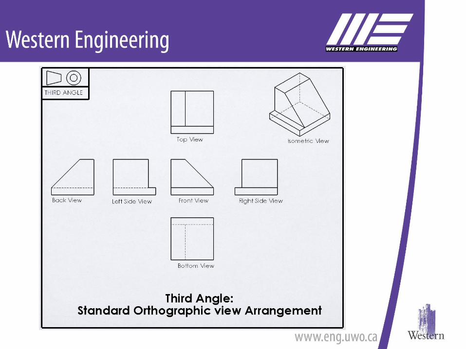
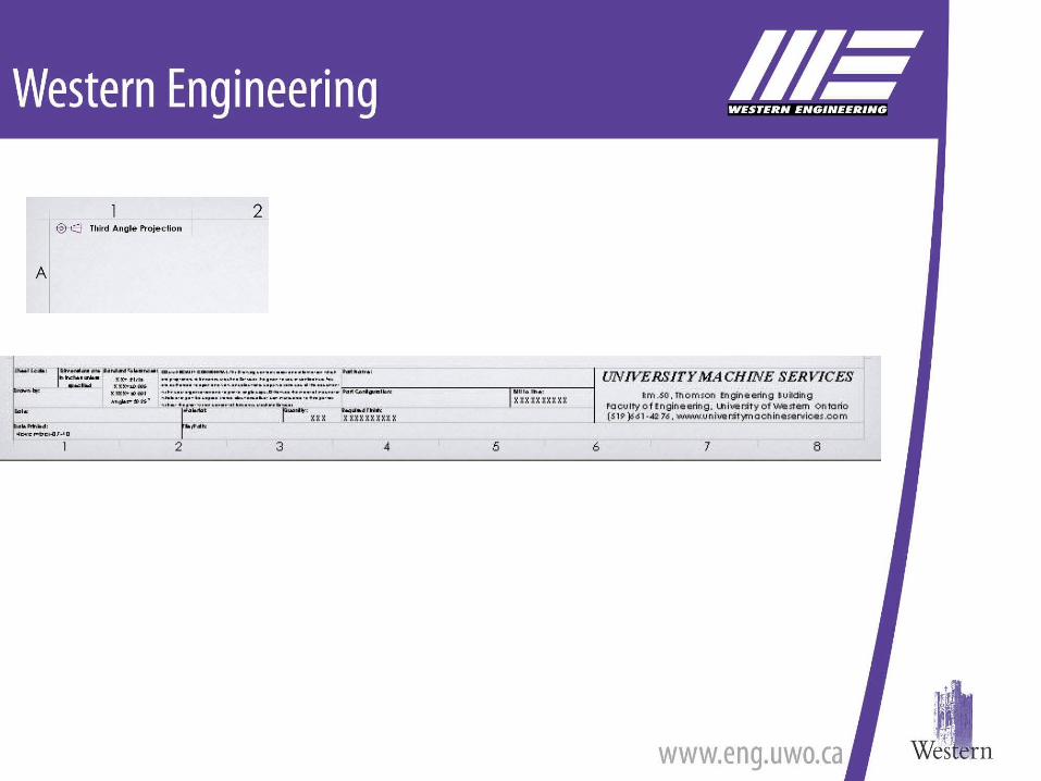
This shows: Third Angle Projection
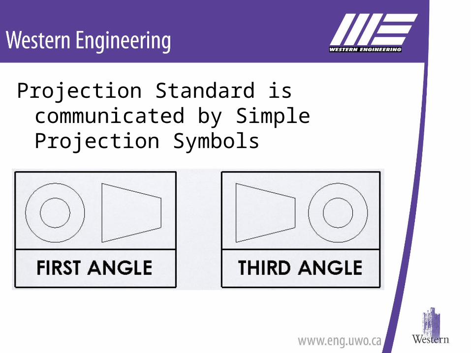
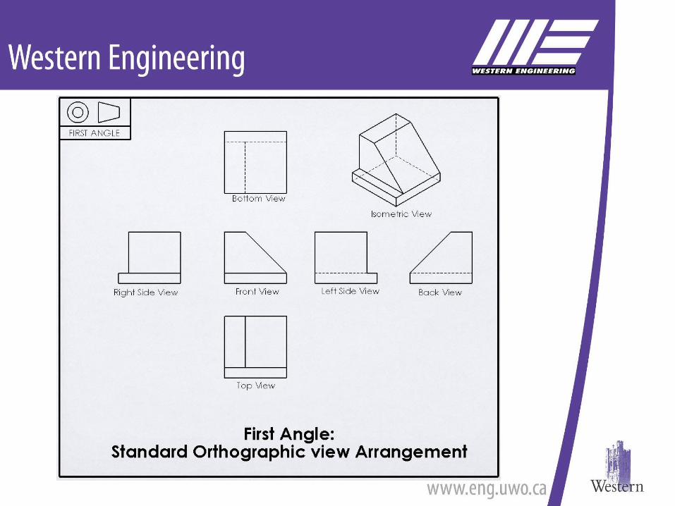
Projection Standard is communicated by Simple Projection Symbols
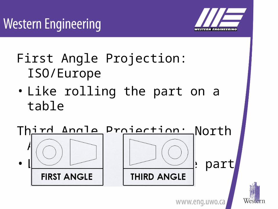
First Angle Projection: ISO/Europe• Like rolling the part on a table
Third Angle Projection: North America• Like walking around the part
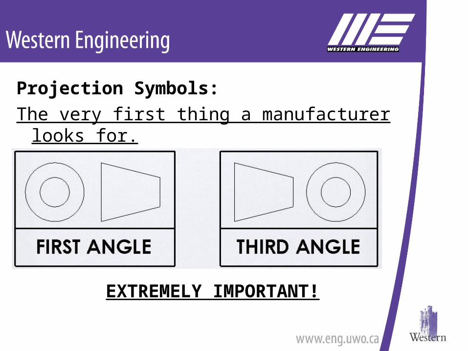
Projection Symbols:The very first thing a manufacturer looks for.
EXTREMELY IMPORTANT!
Orthographic ViewsSometimes can’t show everything
Additional Views may be required
Additional Views Include:•Section Views•Cut-away Views•Broken Views•Revolved Section Views
Not as common
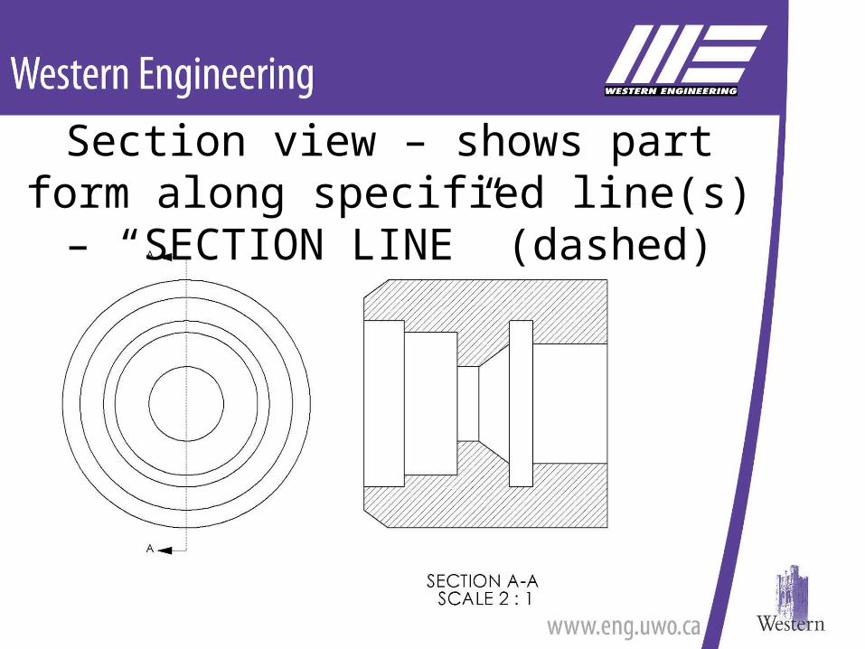
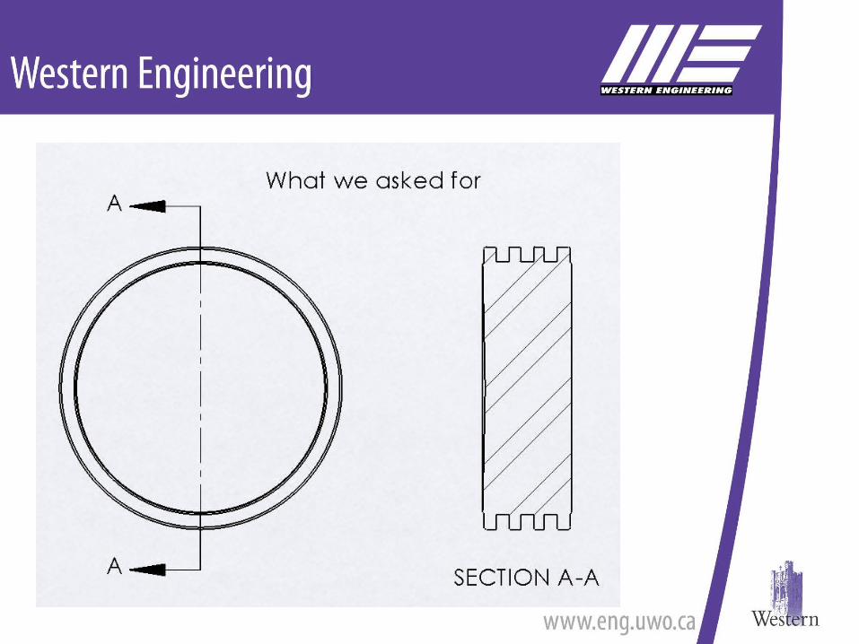
Section view – shows part form along specified line(s) – “SECTION LINE” (dashed)
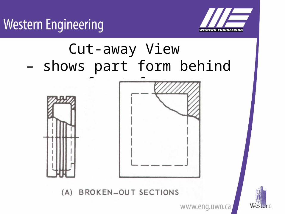
Cut-away View – shows part form behind front face
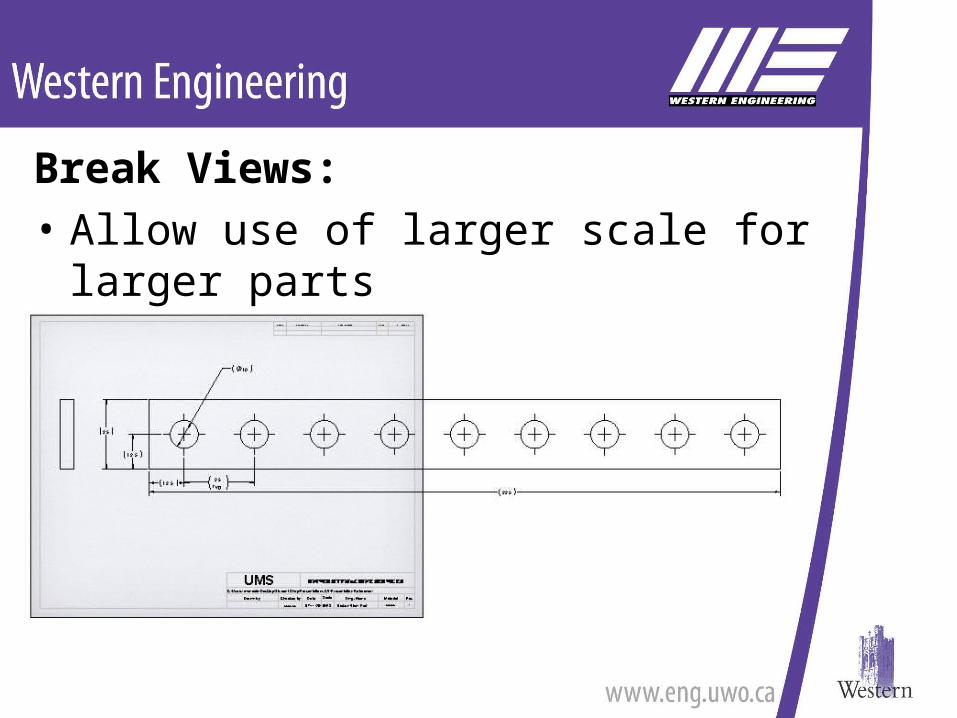
Break Views:• Allow use of larger scale for larger parts
– Smaller drawings
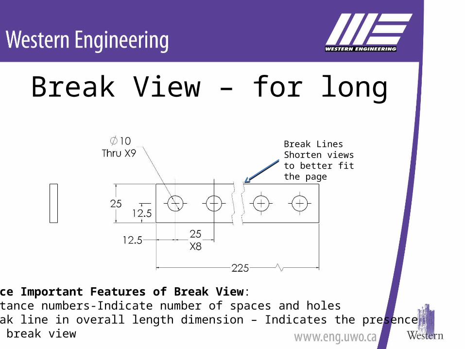
Break View – for long parts
Notice Important Features of Break View:•Instance numbers-Indicate number of spaces and holes•Break line in overall length dimension – Indicates the presence of a break view
Break LinesShorten views to better fit the page
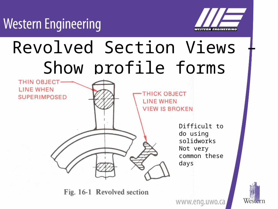
Revolved Section Views – Show profile forms
Difficult to do using solidworksNot very common these days
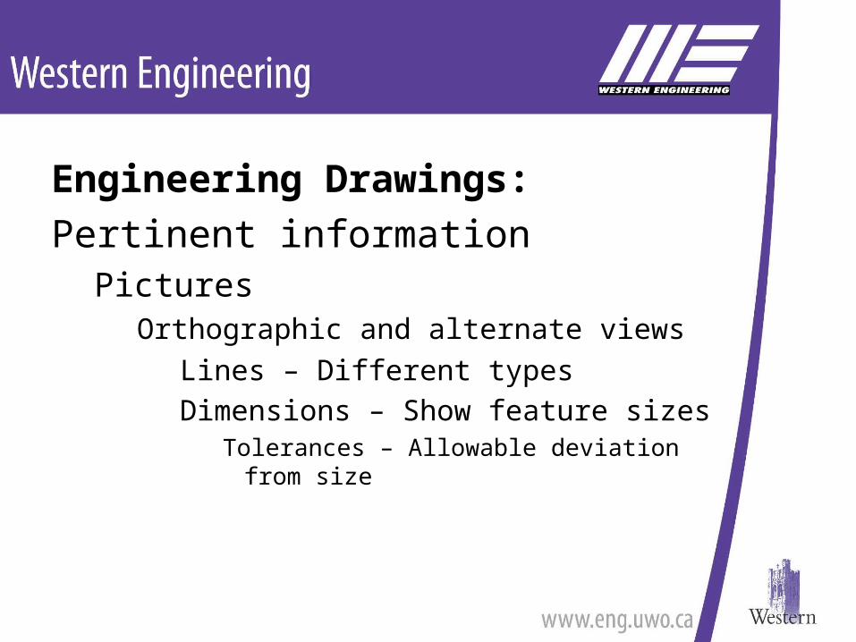
Engineering Drawings: Contain only pertinent information
PicturesOrthographic and alternate views
Lines – Different lines mean different things
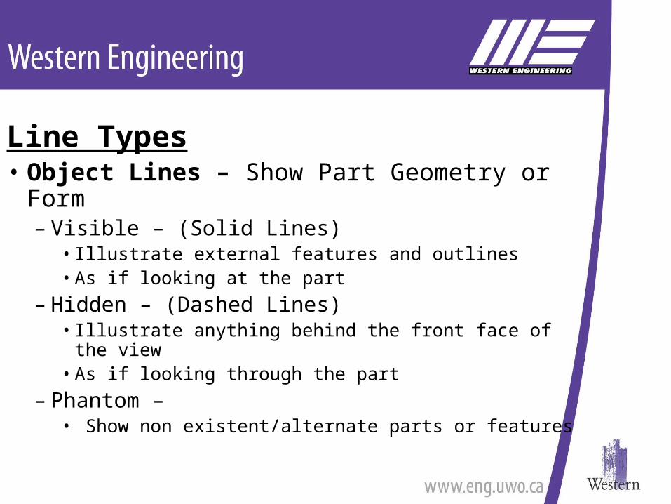
Line Types• Object Lines – Show Part Geometry or Form
– Visible – (Solid Lines)• Illustrate external features and outlines• As if looking at the part
– Hidden – (Dashed Lines) • Illustrate anything behind the front face of the view• As if looking through the part
– Phantom – • Show non existent/alternate parts or features
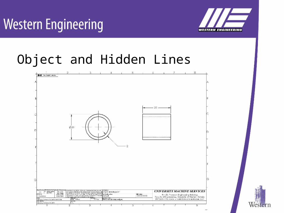
Object and Hidden Lines
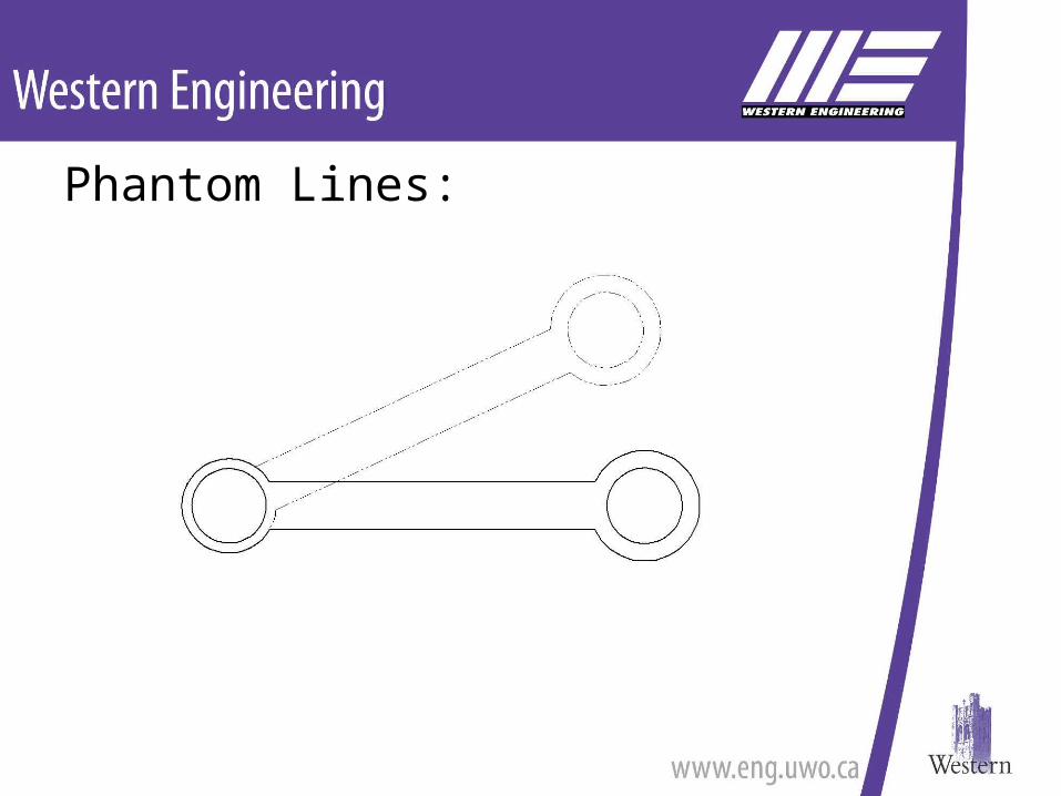
Phantom Lines:
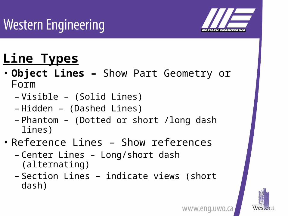
Line Types• Object Lines – Show Part Geometry or Form
– Visible – (Solid Lines)– Hidden – (Dashed Lines) – Phantom – (Dotted or short /long dash lines)
• Reference Lines – Show references– Center Lines – Long/short dash (alternating)– Section Lines – indicate views (short dash)
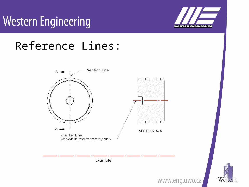
Reference Lines:
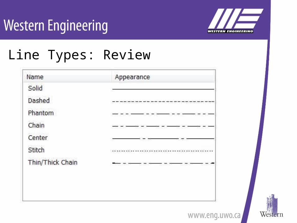
Line Types: Review
Engineering Drawings: Pertinent information
PicturesOrthographic views
Lines – Different typesDimensions – Show feature sizes
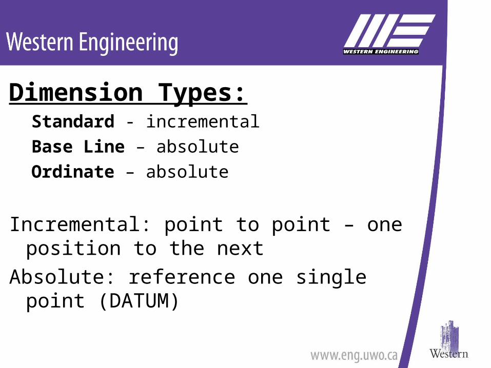
Dimension Types:Standard - incrementalBase Line – absoluteOrdinate – absolute
Incremental: point to point – one position to the next
Absolute: reference one single point (DATUM)
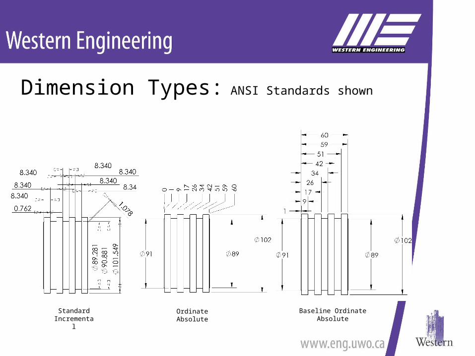
Dimension Types: ANSI Standards shown
Baseline OrdinateAbsolute
StandardIncremental
OrdinateAbsolute
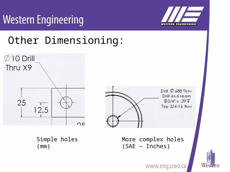
Other Dimensioning:
Simple holes(mm)
More complex holes(SAE – Inches)
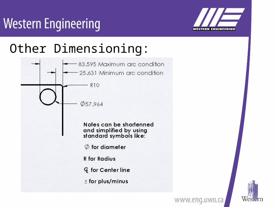
Other Dimensioning:
Engineering Drawings: Pertinent information
PicturesOrthographic and alternate views
Lines – Different typesDimensions – Show feature sizes
Tolerances – Allowable deviation from size
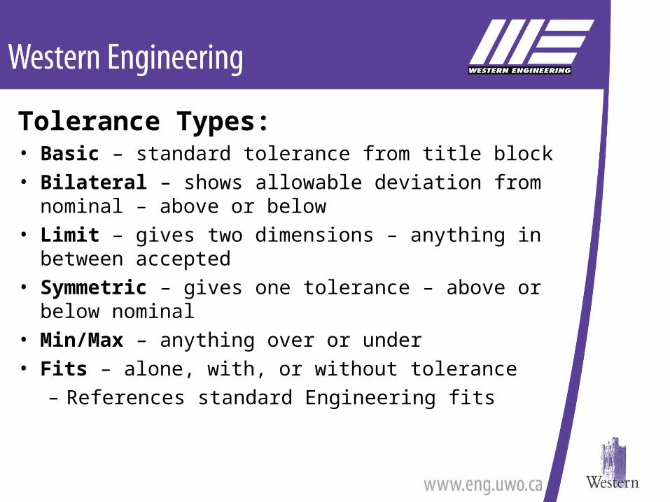
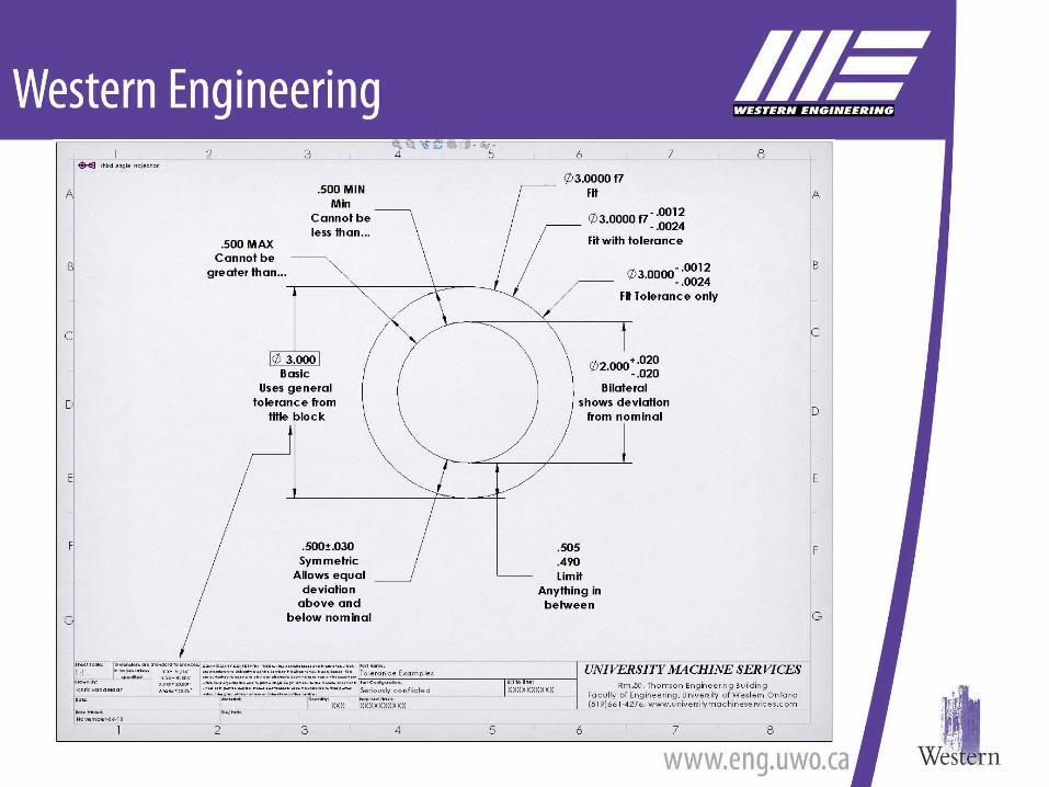
Tolerance Types:• Basic – standard tolerance from title block• Bilateral – shows allowable deviation from nominal –
above or below• Limit – gives two dimensions – anything in between
accepted• Symmetric – gives one tolerance – above or below
nominal• Min/Max – anything over or under• Fits – alone, with, or without tolerance
– References standard Engineering fits
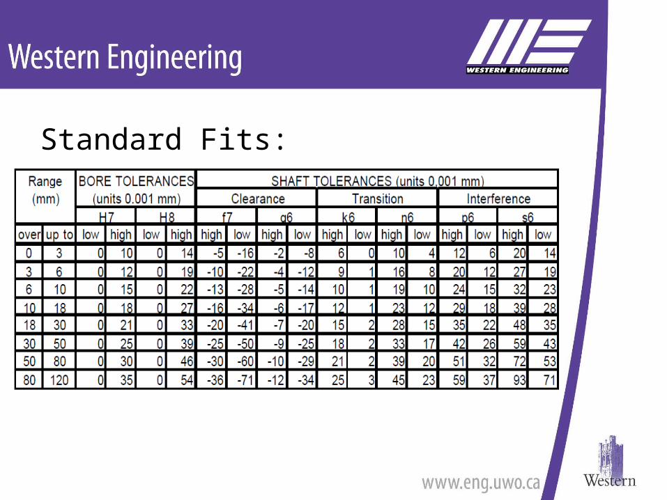
Standard Fits:
Engineering Drawings: Pertinent information
PicturesOrthographic and alternate views
Lines – Different typesDimensions – Show feature sizes
Geometric Dimensioning and tolerancing – (GD&T)
Geometric Dimensioning and Tolerancing:
GD&T• The allowable deviation from
nominal form
GD&T Uses:1.Datum – point of reference
– Face, Edge or Hole
2.Symbol – type of deviation3.Tolerance – allowable variation
– Given as distance
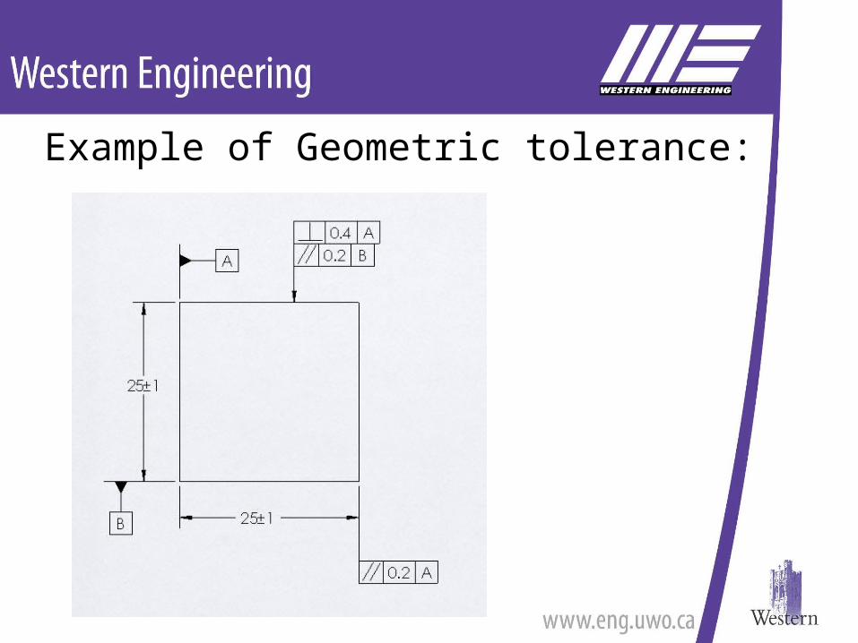
Example of Geometric tolerance:
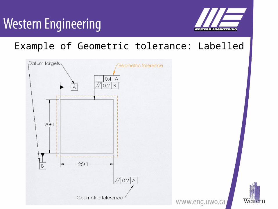
Example of Geometric tolerance: Labelled
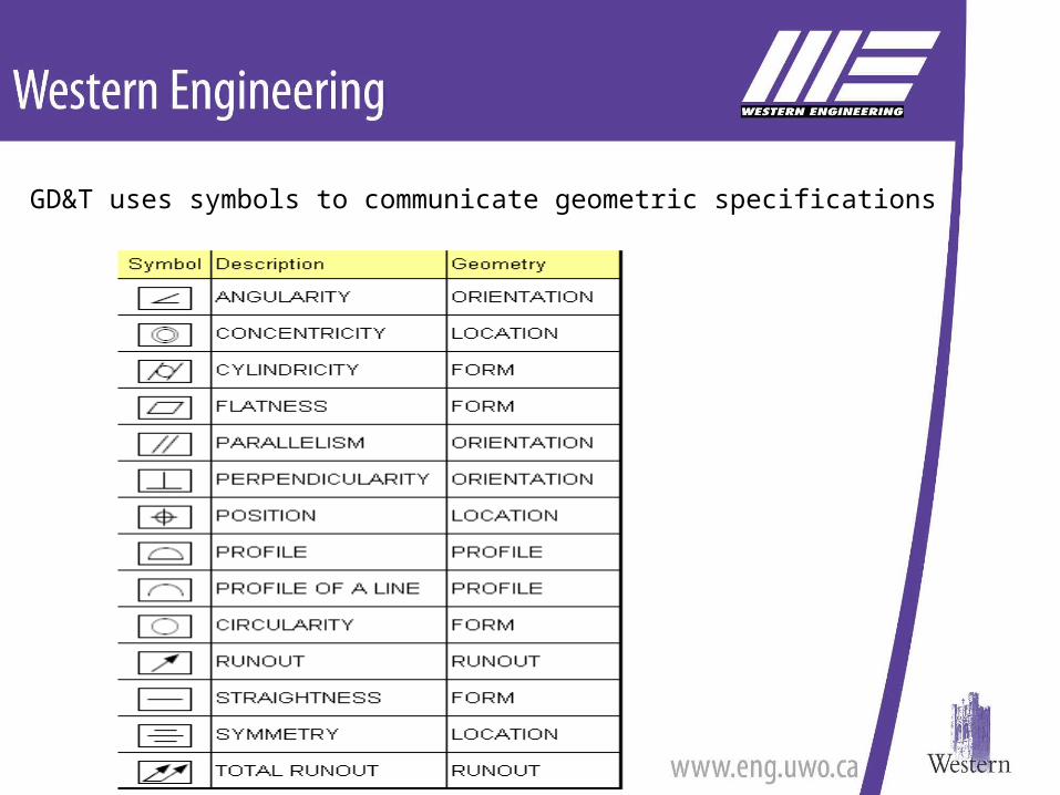
GD&T uses symbols to communicate geometric specifications
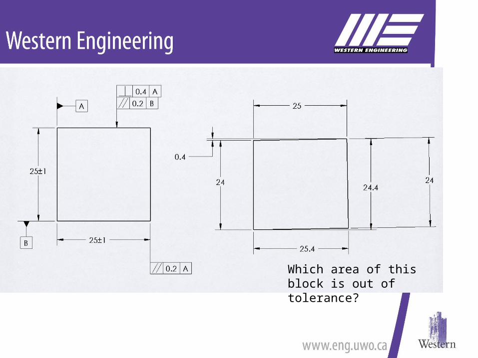
Which area of this block is out of tolerance?
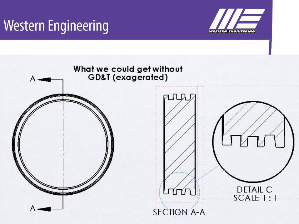
GD&T is the only way to guarantee correct form
Dimensions only guarantee size
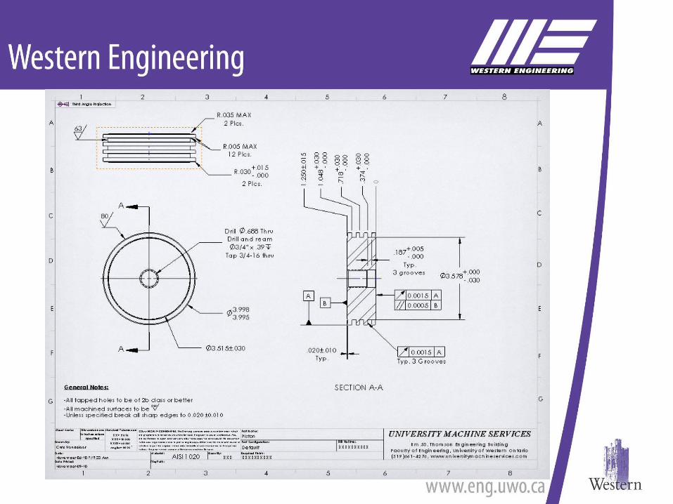
Drawing views:Contain some or all of the following:1.Dimensions2.Tolerances3.Geometric Tolerancing4.Surface finish information5.Allowable tool mark information
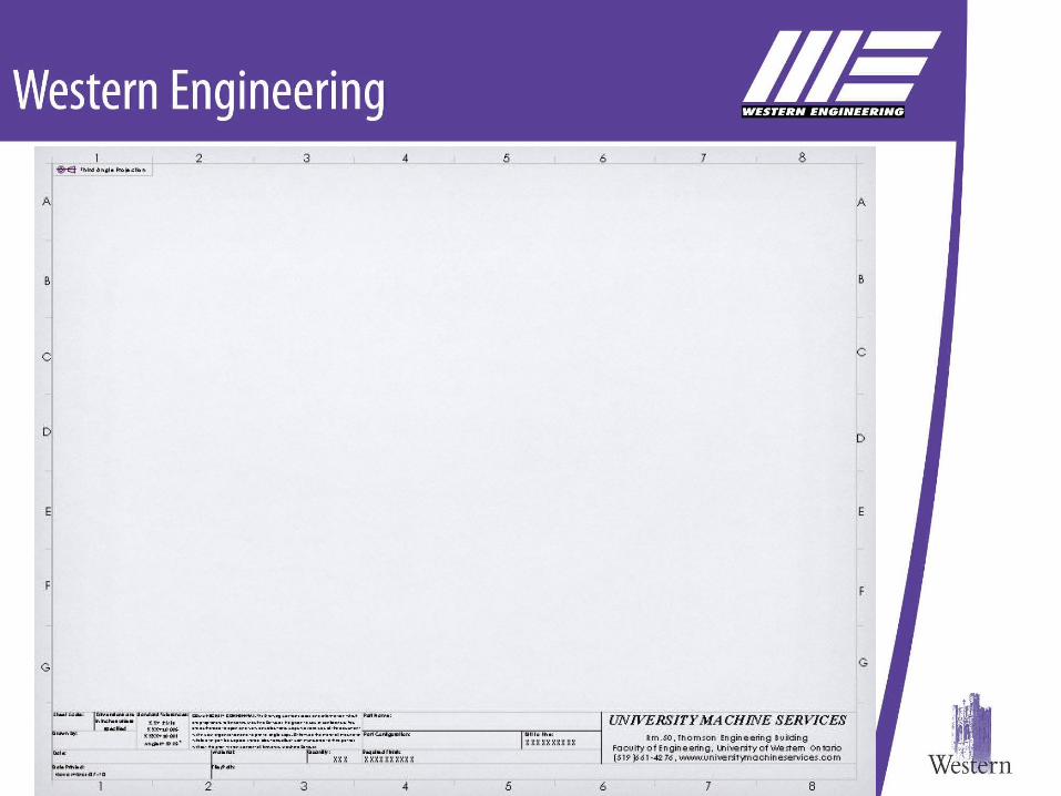
Drawings Contain:1.Drawing Templates or Borders2.Drawing Views3.Title Block4.Revision Block5.Notes – special or standard
Title Blocks:Can vary in:
– Size– Content– Location
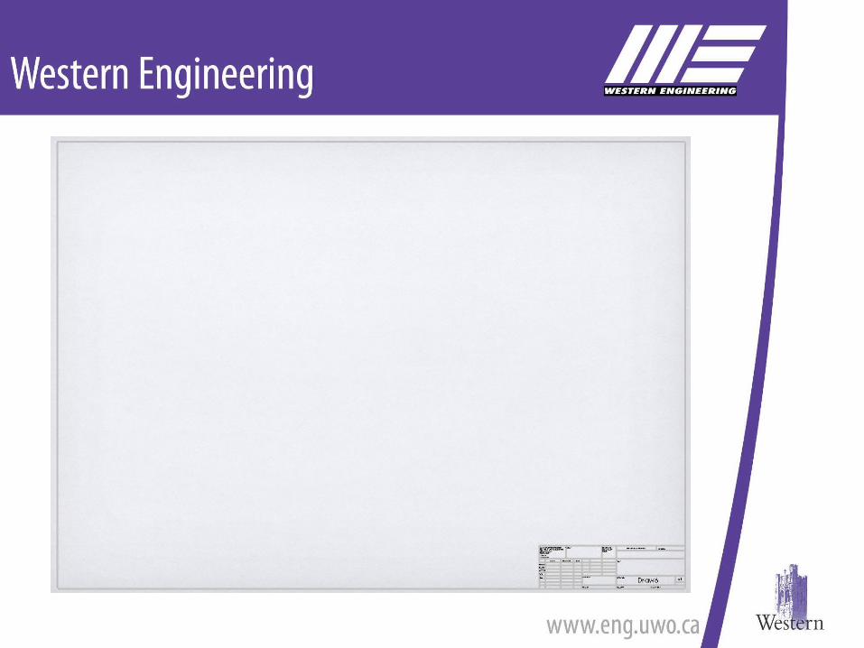
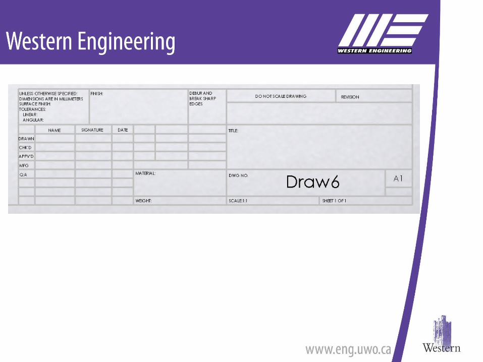
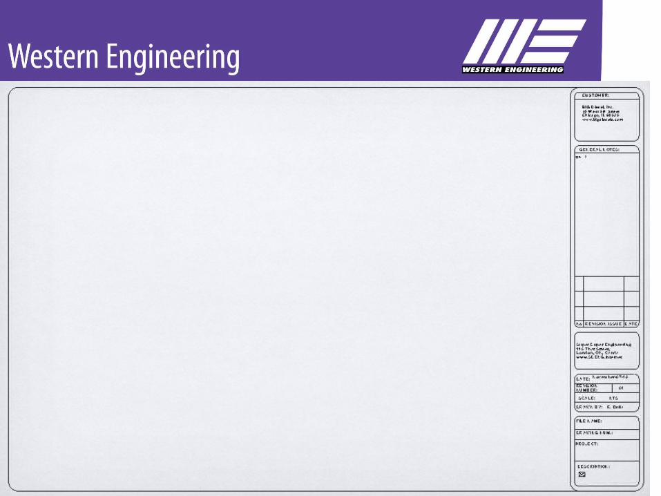
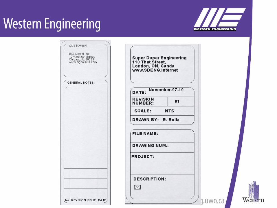
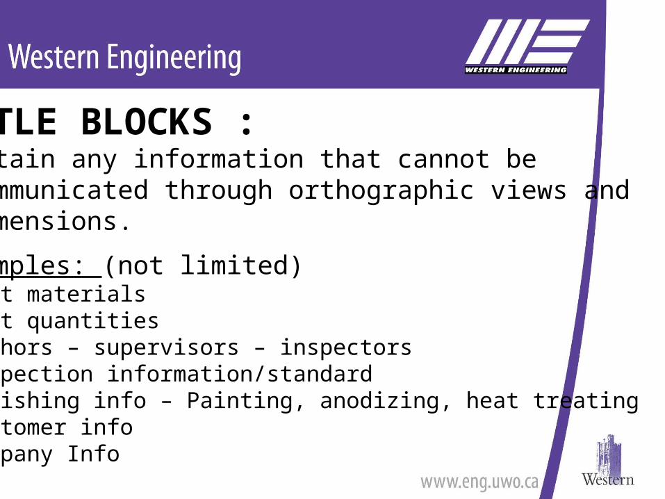
TITLE BLOCKS :Contain any information that cannot be communicated through orthographic views and dimensions.
Examples: (not limited)•Part materials•Part quantities•Authors – supervisors – inspectors•Inspection information/standard•Finishing info – Painting, anodizing, heat treating•Customer info•Company Info
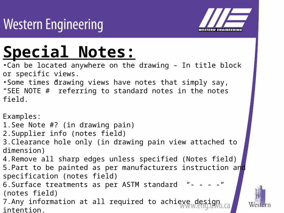
Special Notes:•Can be located anywhere on the drawing – In title block or specific views.•Some times drawing views have notes that simply say, “SEE NOTE #” referring to standard notes in the notes field.
Examples:1.See Note #? (in drawing pain)2.Supplier info (notes field)3.Clearance hole only (in drawing pain view attached to dimension)4.Remove all sharp edges unless specified (Notes field)5.Part to be painted as per manufacturers instruction and specification (notes field)6.Surface treatments as per ASTM standard “- - - -“ (notes field)7.Any information at all required to achieve design intention.
FOR NON-STANDARD INFORMATION
THE ENDIntroduction to Engineering
DrawingsBy: Chris Vandelaar
University Machine ServicesTEB Rm. 50
Resources: Doug Phillips – Previous MME259A presentation Interpreting Engineering Drawings 3rd edition by Jensen & Hines