Mismatched understandings? Findings from a study of vulnerability Kate Brown.
1
Structural Verification of the First Orbital Wonder of the World – The Structural Testing and Analysis of the International Space Station (ISS)
John J. Zipay / Deputy Branch Chief, Structures Branch NASA-Lyndon B. Johnson Space Center, Houston, TX.;
Karen S. Bernstein / Senior Structural Engineer NASA-Lyndon B. Johnson Space Center, Houston, TX.;
Erica E. Bruno / Structural Project Leader for Cargo Analysis United Space Alliance, Houston, TX;
Phillipe Deloo / Nodes & Cupola Project Manager European Space Agency-ESTEC, Noordwijk, The Netherlands;
Raymond Patin / Senior Fracture Mechanics Engineer NASA-Lyndon B. Johnson Space Center, Houston, TX.
Introduction
The International Space Station (ISS) can be considered one of the structural engineering wonders of the world. On par with the World Trade Center, the Colossus of Rhodes, the Statue of Liberty, the Great Pyramids, the Petronas towers and the Burj Khalifa skyscraper of Dubai, the ambition and scope of the ISS structural design, verification and assembly effort is a truly global success story. With its on-orbit life projected to be from its beginning in 1998 to the year 2020 (and perhaps beyond), all of those who participated in its development can consider themselves part of an historic engineering achievement representing all of humanity.
The structural design and verification of the ISS could be the subject of many scholarly papers. Several papers have been written on the structural dynamic characterization of the ISS once it was assembled on-orbit [1], but the ground-based activities required to assure structural integrity and structural life of the individual elements from delivery to orbit through assembly and planned on-orbit operations have never been totally summarized. This paper is intended to give the reader an overview of some of the key decisions made during the structural verification planning for the elements of the U.S. On-Orbit Segment (USOS) as well as to summarize the many structural tests and structural analyses that were performed on its major elements. An effort is made for this paper to be summarily comprehensive, but as with all knowledge capture efforts of this kind, there are bound to be errors of omission. Should the reader discover any of these, please feel free to contact the principal author.
The ISS (Figure 1) is composed of pre-integrated truss segments and pressurized elements supplied by NASA, the Russian Federal Space Agency (RSA), the European Space Agency (ESA) and the Japanese Aerospace Exploration Agency (JAXA). Each of these elements was delivered to orbit by a launch vehicle and connected to one another either robotically or autonomously. The primary structure of each element was assembled and verified by teams of responsible structural engineers within and among their respective agencies and agency contractors. This paper is primarily focused on the structural
https://ntrs.nasa.gov/search.jsp?R=20110013394 2018-05-17T03:37:00+00:00Z

2
verification of the NASA-provided elements of the ISS, since that was the principal author’s primary responsibility and area of knowledge. Where joint structural verification activities were performed between NASA and an International Partner, these activities will be summarized. It is left to the various International Partners to publish detailed accounts of the structural verification efforts for their particular contributions to the ISS.
Figure 1 – The International Space Station (ISS) as seen during the fly-around of the Space Shuttle Atlantis (OV-104) during the STS-132 mission in May, 2010.
Summary of ISS Structural Verification
In all human endeavors, both budget and schedule constraints must be accommodated while still producing the required work needed for the project to be successful. The structural verification effort for the ISS elements was no exception. At the inception of the ISS Program, many elements of the Space Station Freedom Program had progressed through their Critical Design Reviews. Others Space Station Freedom hardware was repackaged to accommodate the new assembly sequence which included two early Russian elements, the Functional Cargo Block (FGB) (later named “Zarya”) and the Service Module (later named “Zvezda”). During the ISS Program definition phase, the structural verification testing of the USOS elements was “zero-baselined”, requiring the principal author and his team to justify to ISS

3
Program Management the need for each individual structural test. This section summarizes the overall structural verification philosophy and the baseline structural verification activities for the USOS elements of the ISS which emerged from that process.
Structural Verification Philosophy
The structural integrity of ISS elements during delivery to orbit by the Space Shuttle Orbiter was a safety-of-flight concern. Structural failure of an ISS element in the payload bay of the Orbiter would be a potential catastrophic hazard to the vehicle and crew. Once delivered to orbit, the pressurized modules would be subjected for decades to internal pressure while both the modules and the integrated truss segments would be subjected to on-orbit transient dynamic loads such as docking events, plume impingement, EVA-induced loads and crew exercise. Any structural failure on-orbit could potentially be catastrophic or at the very least would be difficult to repair. With limited on-orbit structural inspection and repair capability, the structural verification approach prior to launch would have to encompass certification of each element for all of the anticipated loading events for its entire service life.
The governing structural requirements documents for the ISS elements were SSP 30558, “Fracture Control Requirements for Space Station”, SSP 30559, “Structural Design and Verification Requirements for Space Station” and SSP 30560, “Glass, Window and Ceramic Structural Design Requirements for Space Station”. These documents were authored by Mr. Orvis E. Pigg/NASA-JSC (retired) during the Space Station Freedom Program and provided the indispensible foundation for development of all of the USOS structures. These documents defined the required tests and analyses for structurally certifying the ISS elements and referenced Space Shuttle requirement documents NSTS 14046, “Payload Verification Requirements” and NSTS-21000-IDD-ISS, “International Space Station Interface Definition Document.” These requirements were flowed to the individual ISS element Prime Item Development Specifications and were addressed in the respective structural verification plans. These plans were negotiated with each hardware developer, the Space Shuttle Program and the ISS Program Office Structures and Mechanical Systems Team.
Typically, each major payload that flies in the Orbiter and is attached to both the longeron and keel locations of the payload bay (“full-bay payloads”) requires a static test, a modal test and an acoustic test to structurally certify the payload for the environments it will experience during delivery to orbit. These test requirements can be tailored for individual payloads, but doing so requires detailed technical rationale which must be approved as an acceptance of risk from all of the stakeholders. Also, since the elements of the ISS would withstand on-orbit loads at locations other than the interfaces that are loaded during launch, dedicated on-orbit loads testing was performed on areas of the ISS elements and major subcomponents where on-orbit loads were critical. In developing the structural verification approach for the USOS elements, there were several areas where technical risk was accepted and structural testing was not performed, with appropriate rationale, in order to reduce overall Program cost and schedule.
4
Structural analysis of each ISS payload element was performed to the indentured part level. SSP 30559 provided the requirements for factors of safety as well as structural analysis methodologies to be used in the certification stress analysis. Each part on the indentured parts list had a structural margin on both yield and ultimate strength written against it or was classified as “non-structural” or “good-by-inspection.” This assured that a responsible stress analyst assessed every part of the element for structural integrity. SSP 30558 required that each part receive a fracture control classification and specified the requirements for hardware deemed “fracture critical”, where failure of the part could result in a catastrophic hazard. A Fracture Control Summary Report for each ISS element was prepared to document the results of this process. Structural life analysis and the verification of the ISS windows to SSP 30560 are discussed in subsequent sections.
Pressurized Element Structural Verification
“Unity” Node
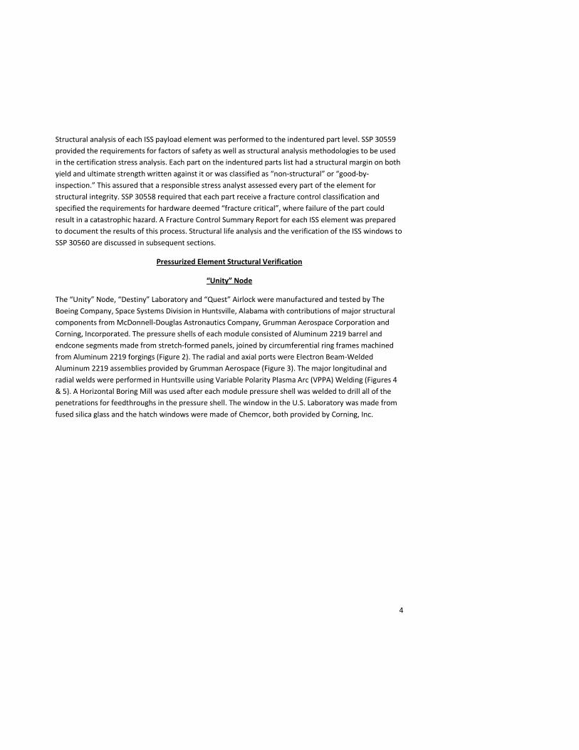
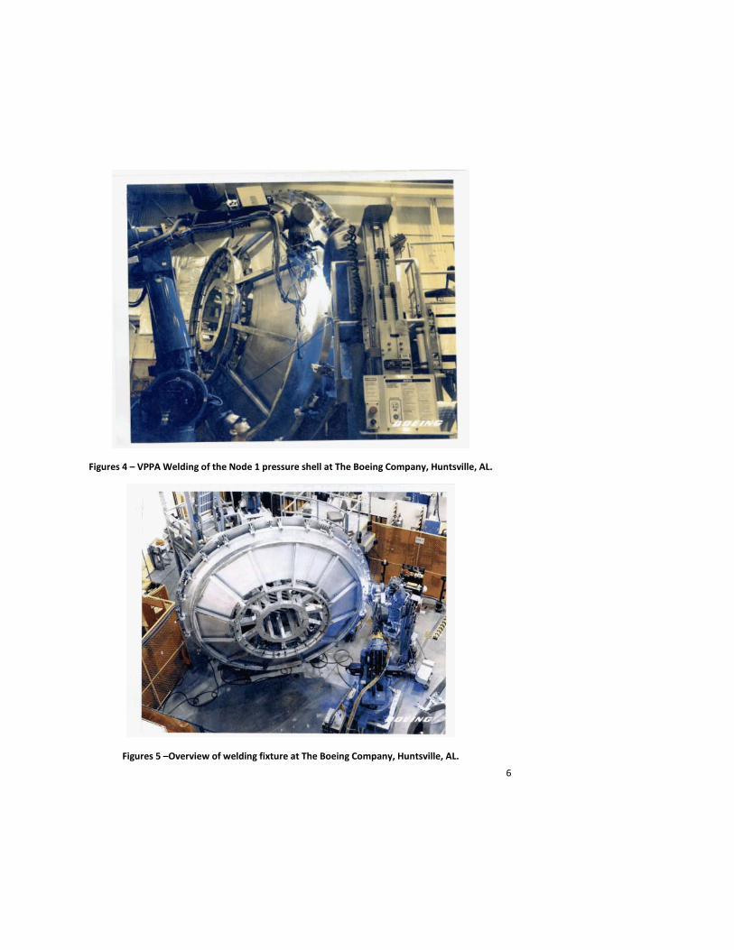
The “Unity” Node, “Destiny” Laboratory and “Quest” Airlock were manufactured and tested by The Boeing Company, Space Systems Division in Huntsville, Alabama with contributions of major structural components from McDonnell-Douglas Astronautics Company, Grumman Aerospace Corporation and Corning, Incorporated. The pressure shells of each module consisted of Aluminum 2219 barrel and endcone segments made from stretch-formed panels, joined by circumferential ring frames machined from Aluminum 2219 forgings (Figure 2). The radial and axial ports were Electron Beam-Welded Aluminum 2219 assemblies provided by Grumman Aerospace (Figure 3). The major longitudinal and radial welds were performed in Huntsville using Variable Polarity Plasma Arc (VPPA) Welding (Figures 4 & 5). A Horizontal Boring Mill was used after each module pressure shell was welded to drill all of the penetrations for feedthroughs in the pressure shell. The window in the U.S. Laboratory was made from fused silica glass and the hatch windows were made of Chemcor, both provided by Corning, Inc.

5
Figure 2 – Node 1 pressure shell structural components.
Figure 3 – Radial Port assembly supplied by Grumman Aerospace.
6
Figures 4 – VPPA Welding of the Node 1 pressure shell at The Boeing Company, Huntsville, AL.
Figures 5 –Overview of welding fixture at The Boeing Company, Huntsville, AL.
7
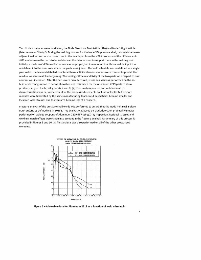
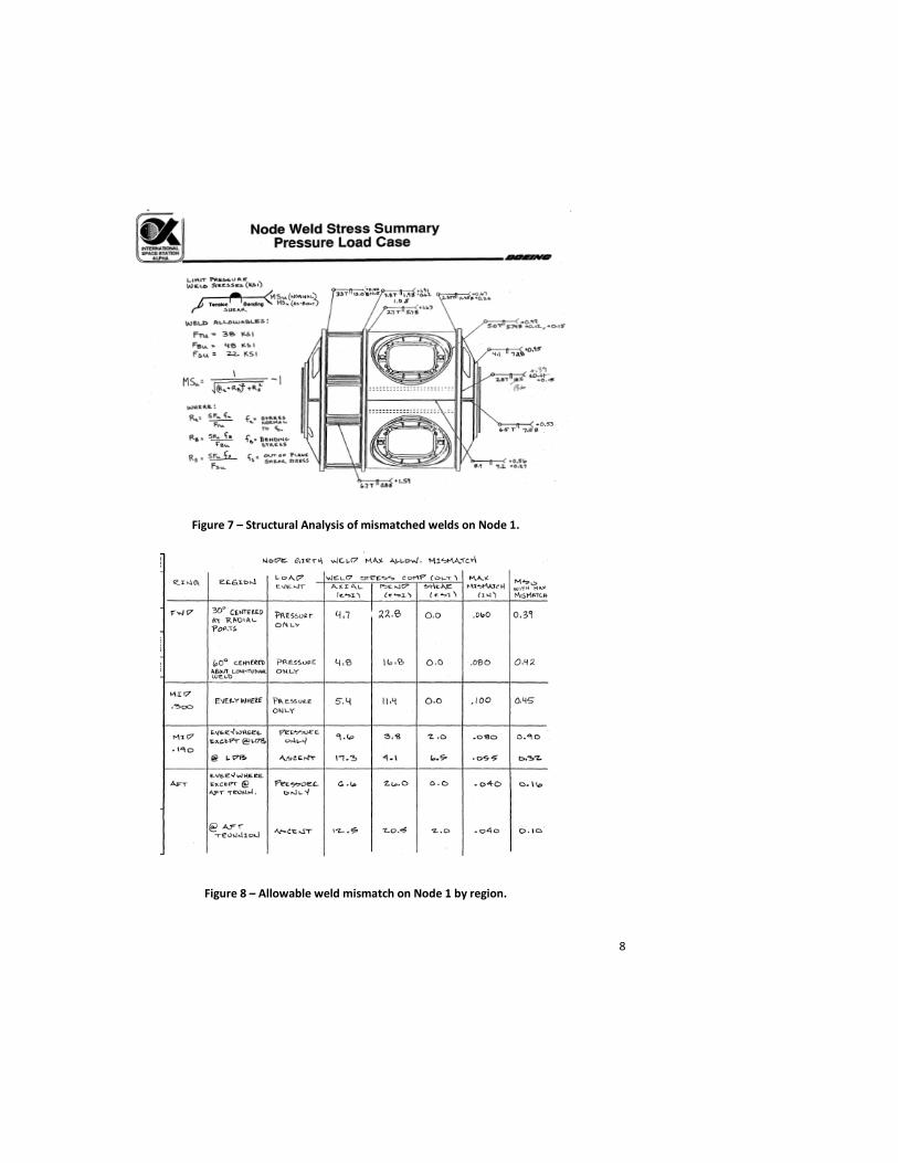
Two Node structures were fabricated, the Node Structural Test Article (STA) and Node 1 flight article (later renamed “Unity”). During the welding process for the Node STA pressure shell, mismatch between adjacent welded sections occurred due to the heat input from the VPPA process and the differences in stiffness between the parts to be welded and the fixtures used to support them in the welding tool. Initially, a dual-pass VPPA weld schedule was employed, but it was found that this schedule input too much heat into the local area where the parts were joined. The weld schedule was re-defined as a single pass weld-schedule and detailed structural-thermal finite element models were created to predict the residual weld mismatch after joining. The tooling stiffness and fixity of the two parts with respect to one another was increased. After the parts were manufactured, stress analysis was performed on the as-built node configuration to define allowable weld mismatch for the Aluminum 2219 parts to show positive margins of safety (Figures 6, 7 and 8) [2]. This analysis process and weld mismatch characterization was performed for all of the pressurized elements built in Huntsville, but as more modules were fabricated by the same manufacturing team, weld mismatches became smaller and localized weld stresses due to mismatch became less of a concern.
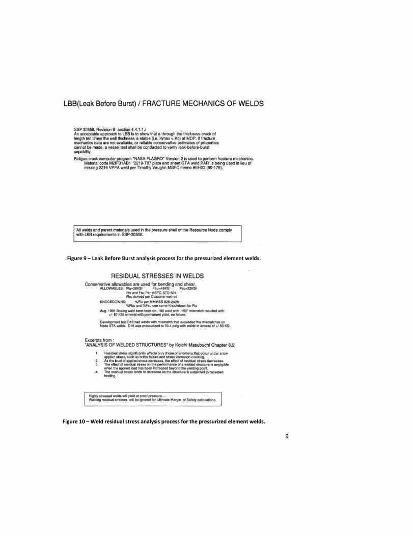
Fracture analysis of the pressure shell welds was performed to assure that the Node met Leak Before Burst criteria as defined in SSP 30558. This analysis was based on crack detection probability studies performed on welded coupons of Aluminum 2219-T87 using X-ray inspection. Residual stresses and weld mismatch effects were taken into account in the fracture analysis. A summary of this process is provided in Figures 9 and 10 [3]. This analysis was also performed on all of the other pressurized elements.
Figure 6 – Allowable data for Aluminum 2219 as a function of weld mismatch.
8
Figure 7 – Structural Analysis of mismatched welds on Node 1.
Figure 8 – Allowable weld mismatch on Node 1 by region.
9
Figure 9 – Leak Before Burst analysis process for the pressurized element welds.
Figure 10 – Weld residual stress analysis process for the pressurized element welds.
10
As originally conceived, the Node and Laboratory module structures were to be certified using dedicated structural test articles. These dedicated test articles would subsequently be refurbished to become flight articles themselves later in the program. As part of the ISS Program baseline, the Airlock was planned to be a protoflight structure to save cost . Therefore, the formulation of the structural test program for these elements required that no ultimate loads testing be performed on any of this hardware and that test loads applied to these elements induce no permanent detrimental deformation. The pressurized elements were designed to a factor of safety of 2.0 x MDP on ultimate, 1.65 x MDP on yield and 1.5 x (pressure + mechanical) loads on ultimate and 1.1 x (pressure + mechanical) loads on yield per SSP 30559.
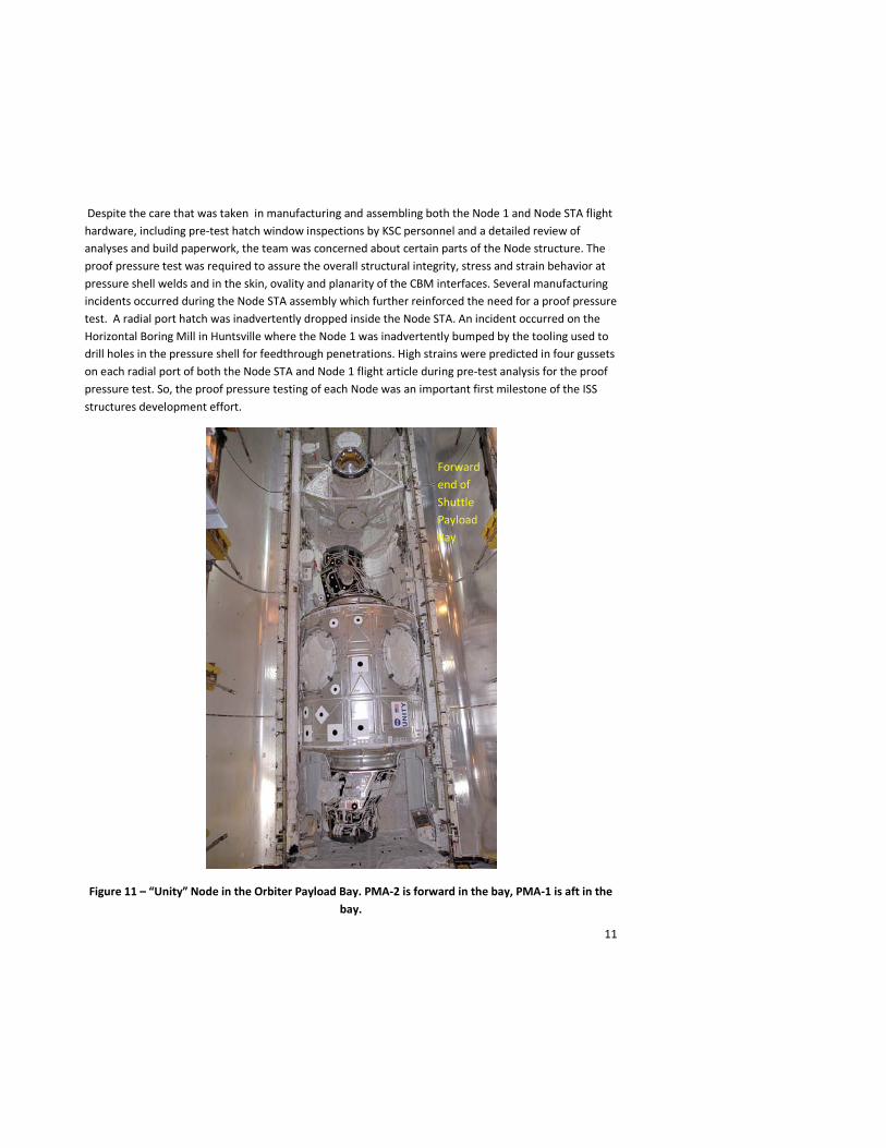
The unique structural verification requirements for Node 1 were driven by its six berthing ports (two axial ports and four radial ports). During launch, the Node 1 would support a Pressurized Mating Adapter (PMA - provided by The Boeing Company, Huntington Beach) from each axial port (Figure 11). Node 1 would interface with the Russian FGB through a PMA attached to its aft axial port (Figure 12) as well as with the U.S. Laboratory attached to its forward axial port. At the time of Node 1’s structural verification (1996-1997), its structural design was identical to that of Node 2, so the Node Structural Test Article’s radial and axial ports would have to be tested to loads which enveloped the anticipated loads for both Node 1 and Node 2. The axial port mechanical loads were driven by the mechanical loads imparted through the Node 1’s aft axial port where it interfaced through PMA-1 to the Russian Functional Cargo Block early in the ISS assembly sequence after the FGB Service Module and Node 1 were attached together (a Progress docking to the aft port of the Service Module while the ISS was a relatively low mass vehicle produced a significant dynamic response). The radial port loads were predicted to be highest for Node 2 when both the Japanese Experiment Module and the Centrifuge Module were attached to adjacent radial ports and subjected to the transient dynamic loads during a Progress vehicle docking. The structural test loads for the Node (STA) axial and radial ports were derived from these particular load cases. So, the Node STA testing was based on a combination of load cases from both Node 1 and Node 2.
The first test performed on the Node STA was a proof pressure test to 1.5 times its maximum design pressure, which for ISS was calculated to be 22.8 pounds per square inch differential (psid). (Maximum Design Pressure (MDP) is calculated assuming two failures within the pressure control system. In other words, the pressurized system must be two-failure tolerant against exceeding the MDP of the hardware.) The test included the Node STA pressure shell, all internal secondary structure as well as pressure domes attached to the zenith radial port Common Berthing Mechanism (CBM) and the aft axial port CBM (Figure 13) [4].
Proof pressure tests of habitable modules, which are intended to verify workmanship and pressure integrity, are not generally used to screen for flaws. To find flaws, Non-Destructive Evaluation (NDE) was performed on all Node STA welds prior to the test. This is NDE included X-Ray and ultrasonic inspections. The proof pressure tests of both the Node STA and the Node 1 flight article were performed at the George C. Marshall Space Flight Center in Huntsville, Alabama.
11
Despite the care that was taken in manufacturing and assembling both the Node 1 and Node STA flight hardware, including pre-test hatch window inspections by KSC personnel and a detailed review of analyses and build paperwork, the team was concerned about certain parts of the Node structure. The proof pressure test was required to assure the overall structural integrity, stress and strain behavior at pressure shell welds and in the skin, ovality and planarity of the CBM interfaces. Several manufacturing incidents occurred during the Node STA assembly which further reinforced the need for a proof pressure test. A radial port hatch was inadvertently dropped inside the Node STA. An incident occurred on the Horizontal Boring Mill in Huntsville where the Node 1 was inadvertently bumped by the tooling used to drill holes in the pressure shell for feedthrough penetrations. High strains were predicted in four gussets on each radial port of both the Node STA and Node 1 flight article during pre-test analysis for the proof pressure test. So, the proof pressure testing of each Node was an important first milestone of the ISS structures development effort.
Figure 11 – “Unity” Node in the Orbiter Payload Bay. PMA-2 is forward in the bay, PMA-1 is aft in the bay.
Forward end of Shuttle Payload Bay

12
Figure 12 – The nascent ISS - “Unity” Node attached to “Zarya” through PMA-1.
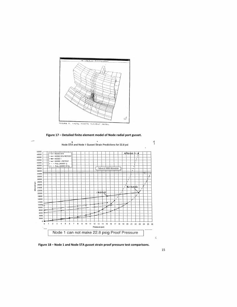
The Node STA proof pressure test demonstrated that the team’s concern about high strain in some gussets were valid. The proof pressure test of the Node STA only achieved 20 psid due to high strains and creep in four gussets stiffening each of the four radial ports (Figures 14 through 18)[5]. The Node 1 Flight Article was pressure tested a few days later in a nearby facility on the Redstone Arsenal and this article only achieved 18 psid due to high strains and creep in the gussets and asymmetric deflections of the pressure shell. The Node 1 Flight Article configuration was different from the Node STA; it consisted only of the pressure shell, CBM’s and hatches with no internal secondary structure or external pressure domes.
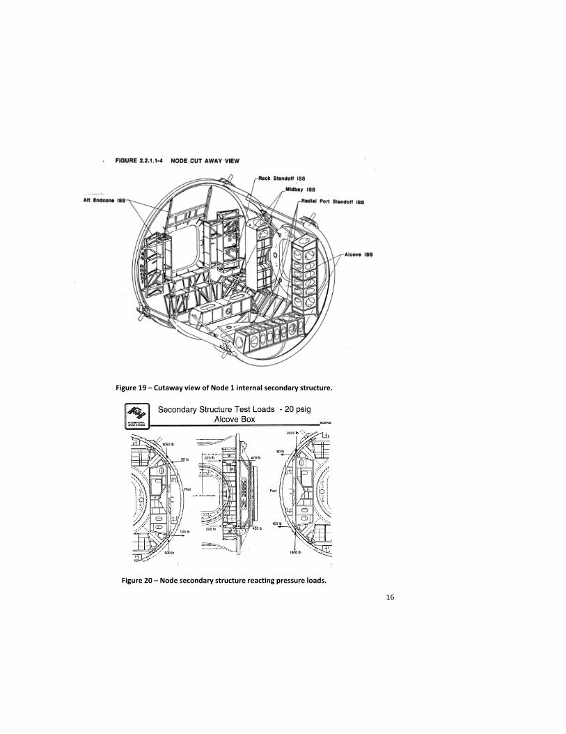
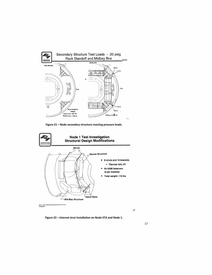
Investigation of these anomalous test results led to the removal of the gussets from both the Node 1 and the Node STA radial ports and the installation of certain common elements of internal secondary structure (two endcone truss and four sets of radial port standoff beams) within each Node which helped react the pressure loads throughout the shell (Figures 19, 20 and 21) [6]. Also, a pair of struts was added between each adjacent pair of radial ports, ostensibly to off-load the gussets, but once the gussets were removed, these struts served to distribute the pressure and mechanical loads more evenly between adjacent radial ports and to limit the deflections at the surface of the radial port Active Common Berthing Mechanism (CBM) ring (Figures 22 and 23) [7].

13
Figure 13 – Diagram of Node STA Proof Pressure and Leak Rate Test Setup.
Figure 14 – Node 1/Node STA Radial Port gussets.

14
Figure 15 - Instrumentation on Node STA Radial Port gussets for proof pressure test.
Figure 16 – Strain gage readings on Nadir radial port gussets during Node STA proof pressure test.
15
Figure 17 – Detailed finite element model of Node radial port gusset.
Figure 18 – Node 1 and Node STA gusset strain proof pressure test comparisons.
16
Figure 19 – Cutaway view of Node 1 internal secondary structure.
Figure 20 – Node secondary structure reacting pressure loads.
17
Figure 21 – Node secondary structure reacting pressure loads.
Figure 22 – Internal strut installation on Node STA and Node 1.
18
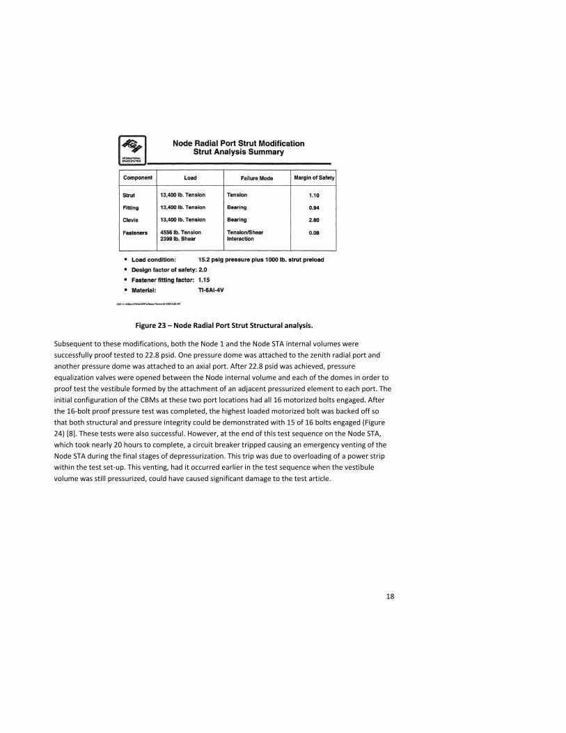
Figure 23 – Node Radial Port Strut Structural analysis.
Subsequent to these modifications, both the Node 1 and the Node STA internal volumes were successfully proof tested to 22.8 psid. One pressure dome was attached to the zenith radial port and another pressure dome was attached to an axial port. After 22.8 psid was achieved, pressure equalization valves were opened between the Node internal volume and each of the domes in order to proof test the vestibule formed by the attachment of an adjacent pressurized element to each port. The initial configuration of the CBMs at these two port locations had all 16 motorized bolts engaged. After the 16-bolt proof pressure test was completed, the highest loaded motorized bolt was backed off so that both structural and pressure integrity could be demonstrated with 15 of 16 bolts engaged (Figure 24) [8]. These tests were also successful. However, at the end of this test sequence on the Node STA, which took nearly 20 hours to complete, a circuit breaker tripped causing an emergency venting of the Node STA during the final stages of depressurization. This trip was due to overloading of a power strip within the test set-up. This venting, had it occurred earlier in the test sequence when the vestibule volume was still pressurized, could have caused significant damage to the test article.

19
Figure 24 – Node STA / Node 1 Proof Pressure / Leak Rate Test Sequence.
Strain gages located across the Node STA and Node 1 pressure shell and on aluminum plates installed in both a radial and an axial hatch window provided stress distributions and internal loads at critical features such as areas of weld mismatch and endcone to cylinder interfaces. Deflection gages monitored overall displacement of both the pressure shell and the CBM rings. Subsequent post-proof NDE and helium leak testing of the welds confirmed the pressure and leakage integrity of the article. Since most of the ISS structures were tested in facilities without tight temperature controls, temperature-compensation of the strain gage readings had to be performed. While this induced error was small, this consideration cannot be overlooked when performing qualification testing for structures when tight math model correlation is required. All stated objectives of the Node 1 and Node STA proof pressure and leak test campaign were satisfied (Figure 25) [9].
20
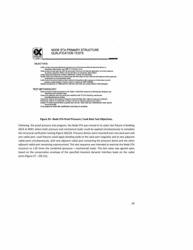
Figure 25– Node STA Proof Pressure / Leak Rate Test Objectives.
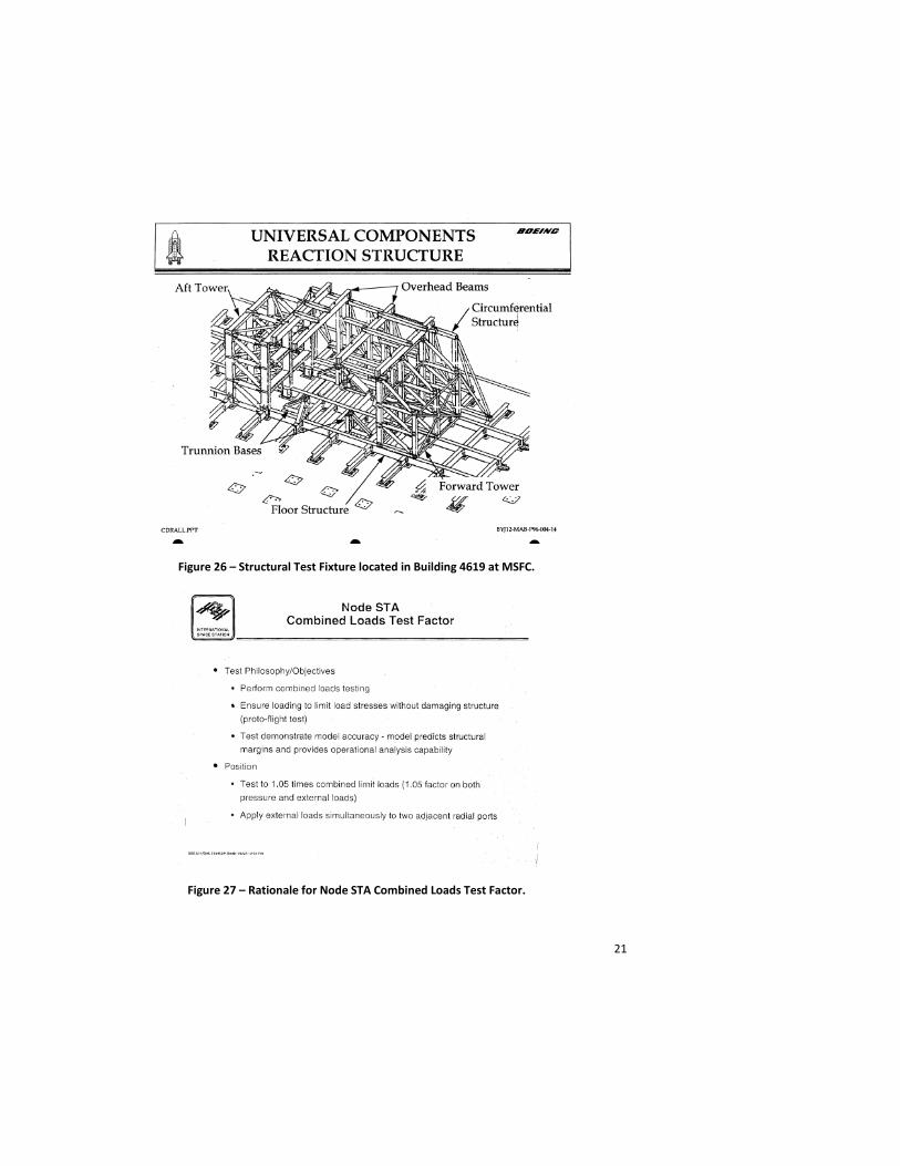
Following the proof pressure test program, the Node STA was moved to its static test fixture in Building 4619 at MSFC where both pressure and mechanical loads could be applied simultaneously to complete the structural verification testing (Figure 26)[10]. Pressure domes were mounted over one axial port and one radial port. Load fixtures could apply bending loads to the axial port singularly and to two adjacent radial ports simultaneously, with one adjacent radial port containing the pressure dome and the other adjacent radial port remaining unpressurized. This test sequence was intended to exercise the Node STA structure to 1.05 times the combined (pressure + mechanical) loads. This test value was agreed upon based on the conservative envelope of the specified transient dynamic interface loads on the radial ports (Figure 27 – 29) [11].
21
Figure 26 – Structural Test Fixture located in Building 4619 at MSFC.
Figure 27 – Rationale for Node STA Combined Loads Test Factor.
22
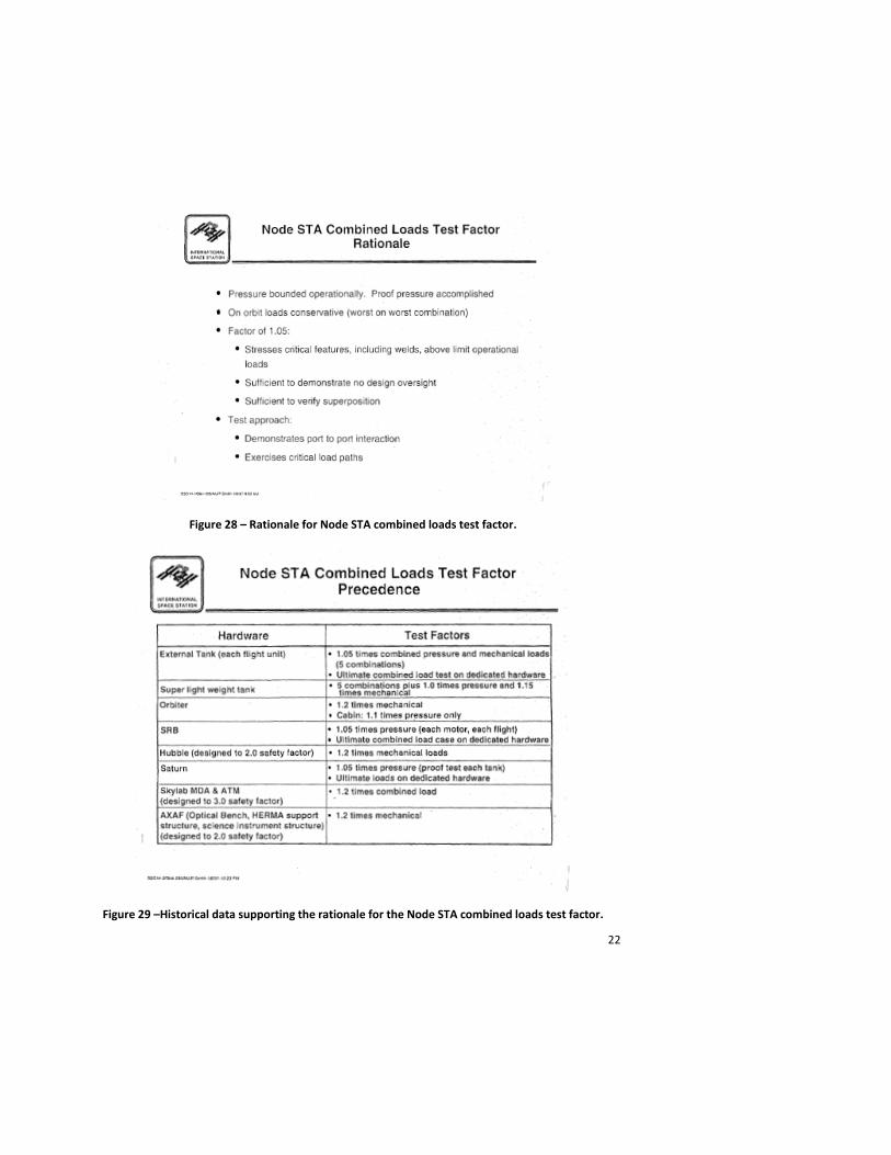
Figure 28 – Rationale for Node STA combined loads test factor.
Figure 29 –Historical data supporting the rationale for the Node STA combined loads test factor.
23
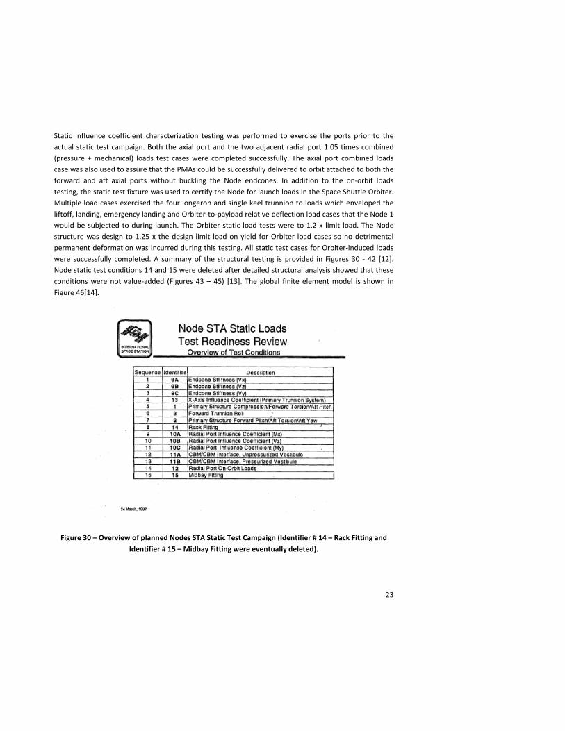
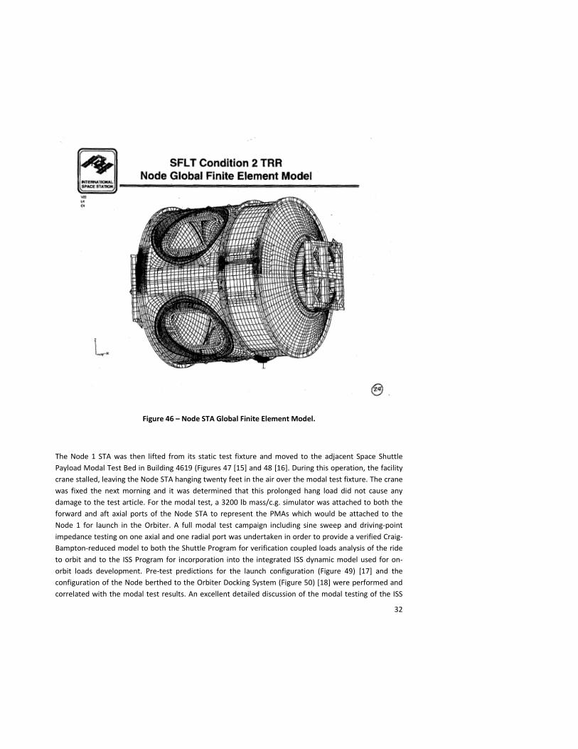
Static Influence coefficient characterization testing was performed to exercise the ports prior to the actual static test campaign. Both the axial port and the two adjacent radial port 1.05 times combined (pressure + mechanical) loads test cases were completed successfully. The axial port combined loads case was also used to assure that the PMAs could be successfully delivered to orbit attached to both the forward and aft axial ports without buckling the Node endcones. In addition to the on-orbit loads testing, the static test fixture was used to certify the Node for launch loads in the Space Shuttle Orbiter. Multiple load cases exercised the four longeron and single keel trunnion to loads which enveloped the liftoff, landing, emergency landing and Orbiter-to-payload relative deflection load cases that the Node 1 would be subjected to during launch. The Orbiter static load tests were to 1.2 x limit load. The Node structure was design to 1.25 x the design limit load on yield for Orbiter load cases so no detrimental permanent deformation was incurred during this testing. All static test cases for Orbiter-induced loads were successfully completed. A summary of the structural testing is provided in Figures 30 - 42 [12]. Node static test conditions 14 and 15 were deleted after detailed structural analysis showed that these conditions were not value-added (Figures 43 – 45) [13]. The global finite element model is shown in Figure 46[14].
Figure 30 – Overview of planned Nodes STA Static Test Campaign (Identifier # 14 – Rack Fitting and Identifier # 15 – Midbay Fitting were eventually deleted).
24
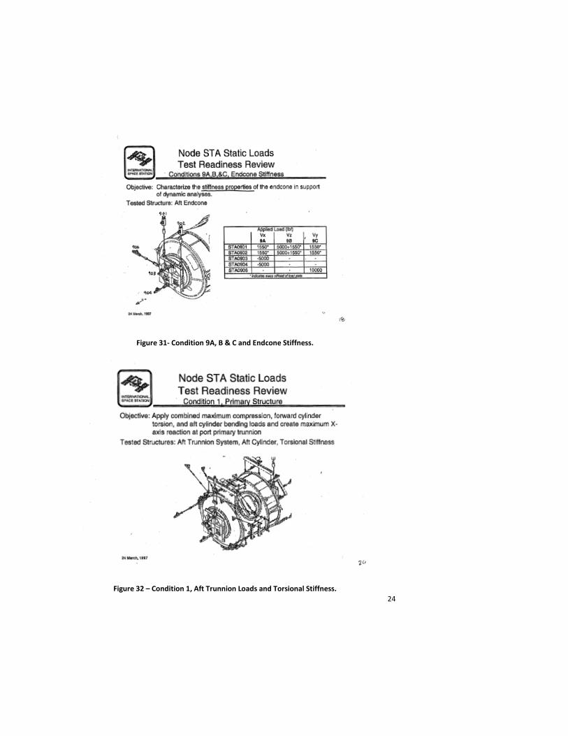
Figure 31- Condition 9A, B & C and Endcone Stiffness.
Figure 32 – Condition 1, Aft Trunnion Loads and Torsional Stiffness.
25
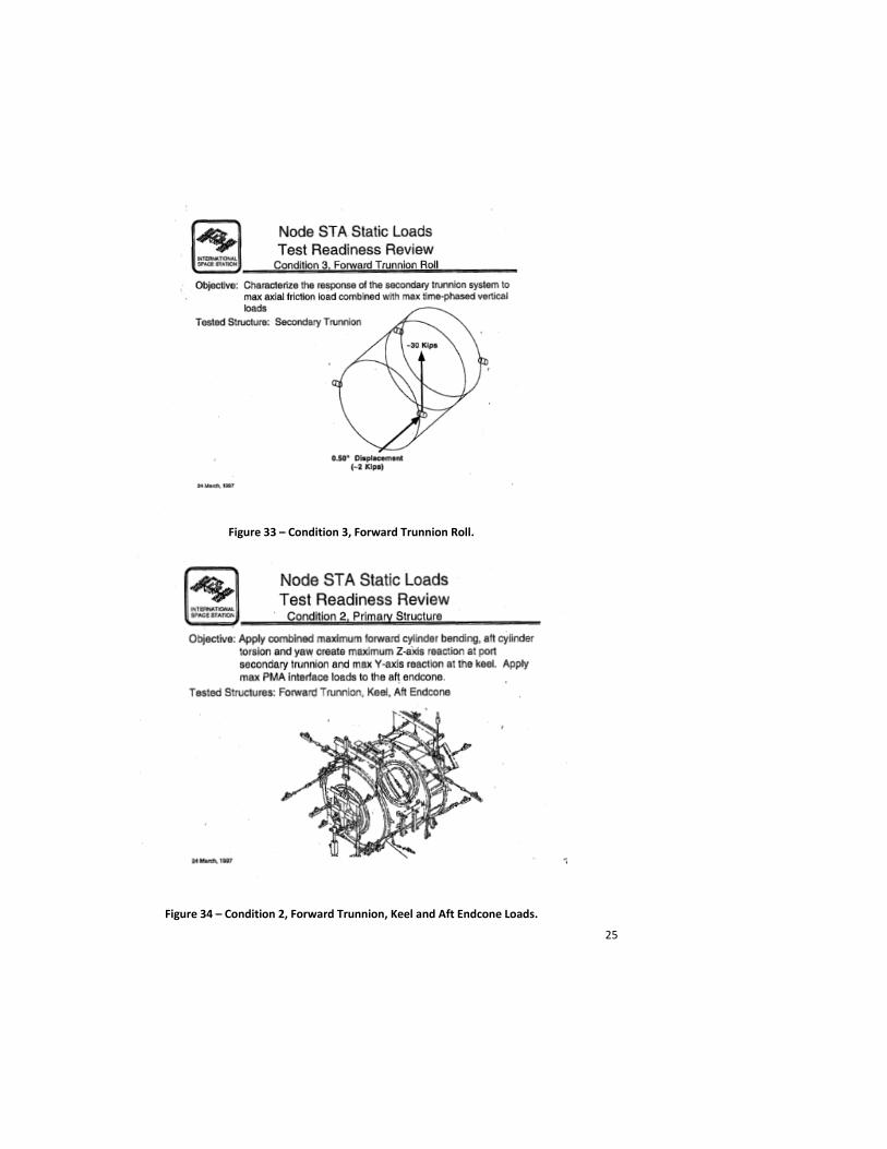
Figure 33 – Condition 3, Forward Trunnion Roll.
Figure 34 – Condition 2, Forward Trunnion, Keel and Aft Endcone Loads.

26
Figure 35 – Condition 14, Rack Fitting Load Case (Subsequently Deleted).
Figure 36 – Condition 10A, Radial Port Influence Coefficient Test.
27
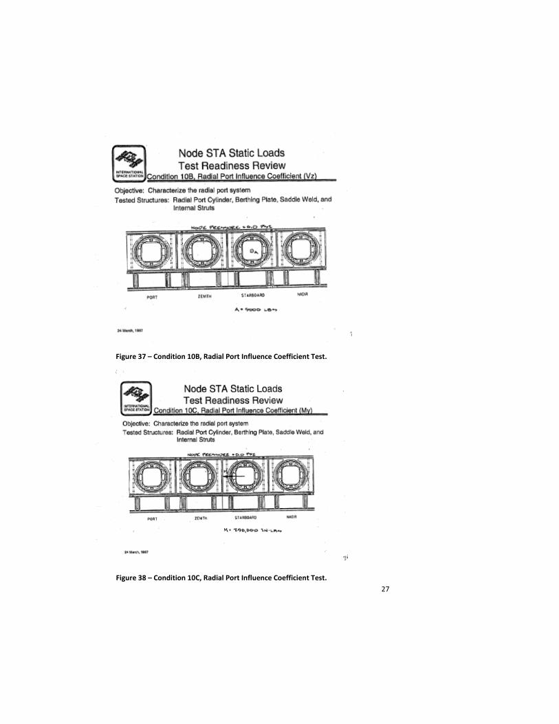
Figure 37 – Condition 10B, Radial Port Influence Coefficient Test.
Figure 38 – Condition 10C, Radial Port Influence Coefficient Test.
28
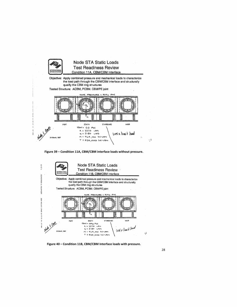
Figure 39 – Condition 11A, CBM/CBM interface loads without pressure.
Figure 40 – Condition 11B, CBM/CBM Interface loads with pressure.
29
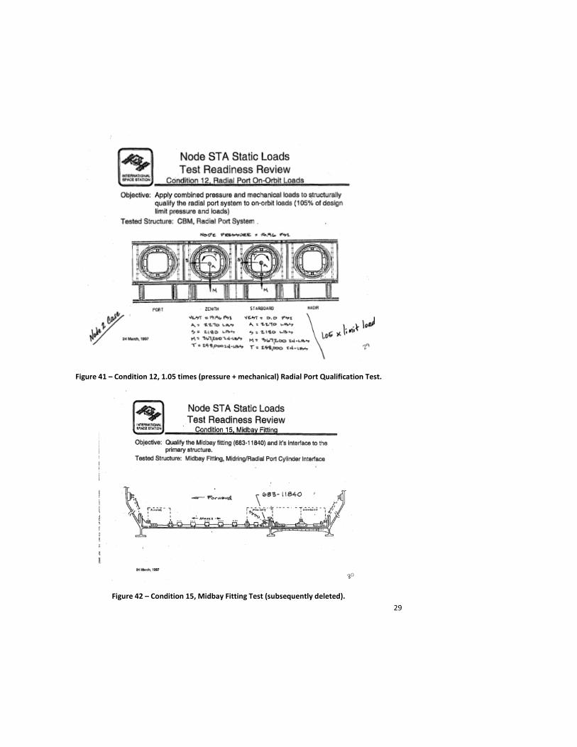
Figure 41 – Condition 12, 1.05 times (pressure + mechanical) Radial Port Qualification Test.
Figure 42 – Condition 15, Midbay Fitting Test (subsequently deleted).
30
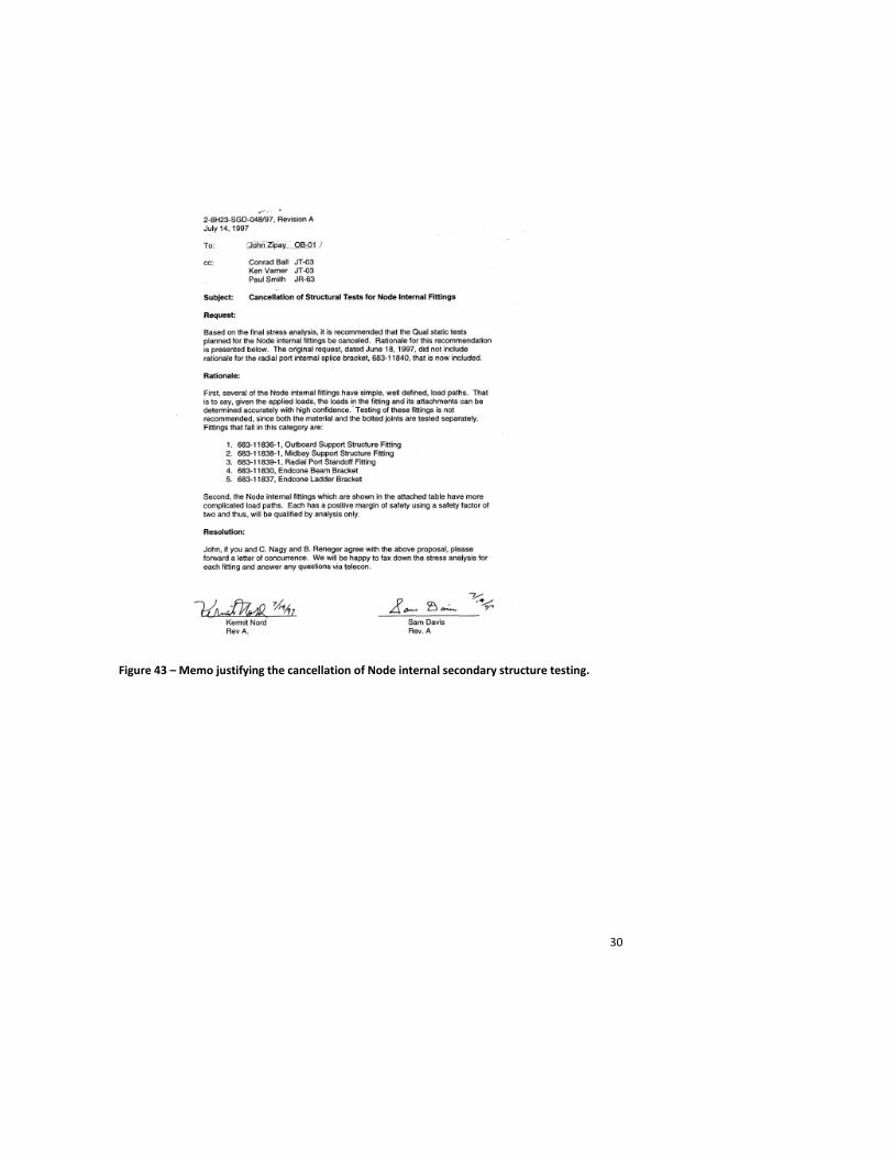
Figure 43 – Memo justifying the cancellation of Node internal secondary structure testing.
31
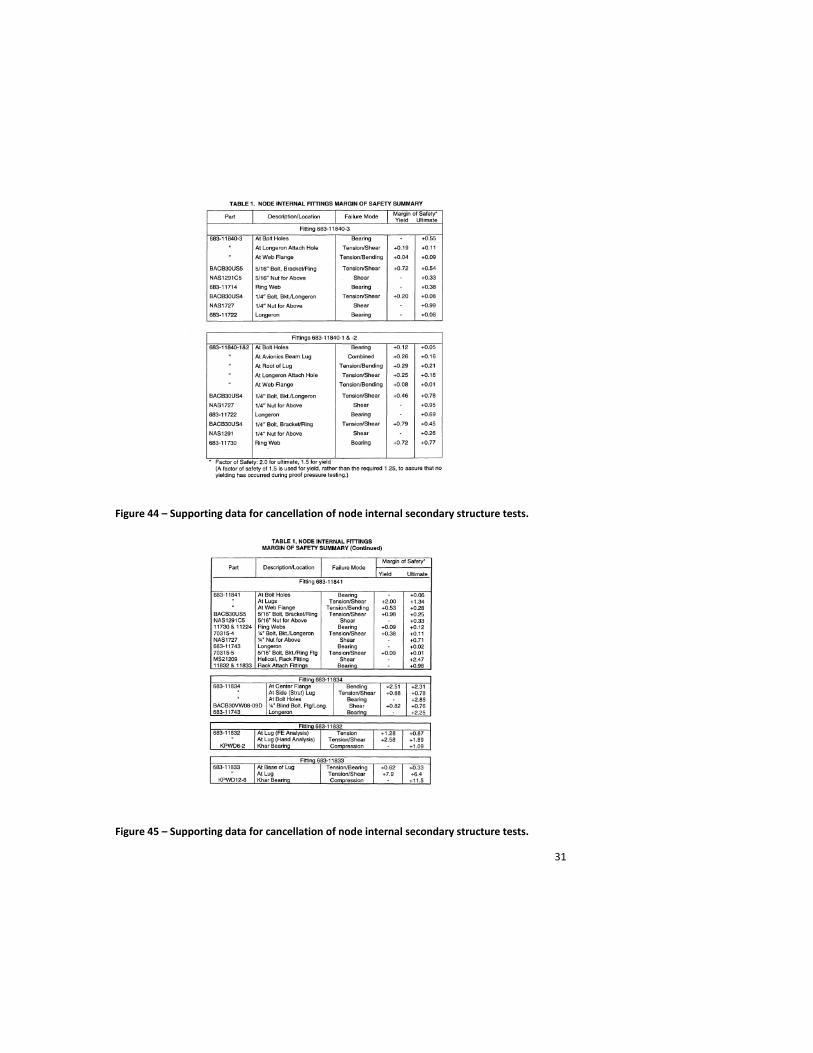
Figure 44 – Supporting data for cancellation of node internal secondary structure tests.
Figure 45 – Supporting data for cancellation of node internal secondary structure tests.
32
Figure 46 – Node STA Global Finite Element Model.
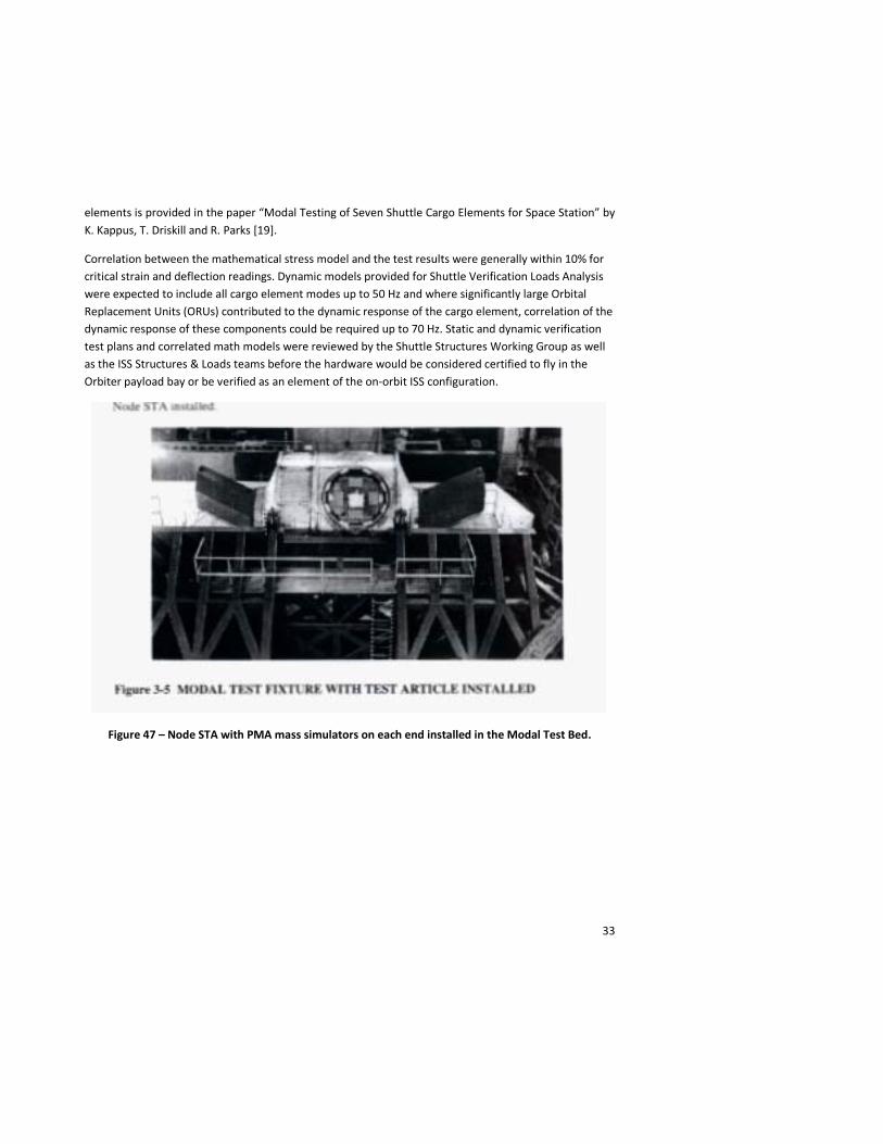
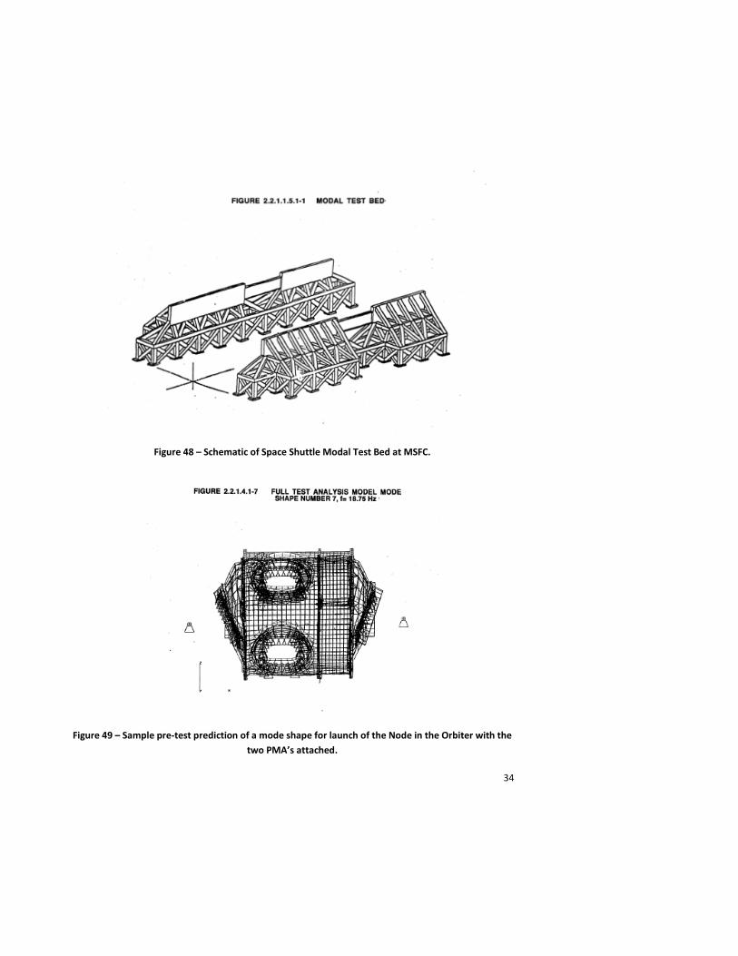
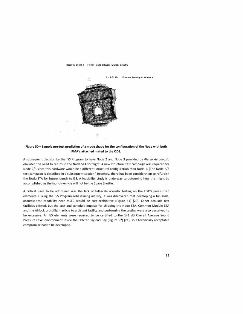
The Node 1 STA was then lifted from its static test fixture and moved to the adjacent Space Shuttle Payload Modal Test Bed in Building 4619 (Figures 47 [15] and 48 [16]. During this operation, the facility crane stalled, leaving the Node STA hanging twenty feet in the air over the modal test fixture. The crane was fixed the next morning and it was determined that this prolonged hang load did not cause any damage to the test article. For the modal test, a 3200 lb mass/c.g. simulator was attached to both the forward and aft axial ports of the Node STA to represent the PMAs which would be attached to the Node 1 for launch in the Orbiter. A full modal test campaign including sine sweep and driving-point impedance testing on one axial and one radial port was undertaken in order to provide a verified Craig-Bampton-reduced model to both the Shuttle Program for verification coupled loads analysis of the ride to orbit and to the ISS Program for incorporation into the integrated ISS dynamic model used for on-orbit loads development. Pre-test predictions for the launch configuration (Figure 49) [17] and the configuration of the Node berthed to the Orbiter Docking System (Figure 50) [18] were performed and correlated with the modal test results. An excellent detailed discussion of the modal testing of the ISS
33
elements is provided in the paper “Modal Testing of Seven Shuttle Cargo Elements for Space Station” by K. Kappus, T. Driskill and R. Parks [19].
Correlation between the mathematical stress model and the test results were generally within 10% for critical strain and deflection readings. Dynamic models provided for Shuttle Verification Loads Analysis were expected to include all cargo element modes up to 50 Hz and where significantly large Orbital Replacement Units (ORUs) contributed to the dynamic response of the cargo element, correlation of the dynamic response of these components could be required up to 70 Hz. Static and dynamic verification test plans and correlated math models were reviewed by the Shuttle Structures Working Group as well as the ISS Structures & Loads teams before the hardware would be considered certified to fly in the Orbiter payload bay or be verified as an element of the on-orbit ISS configuration.
Figure 47 – Node STA with PMA mass simulators on each end installed in the Modal Test Bed.
34
Figure 48 – Schematic of Space Shuttle Modal Test Bed at MSFC.
Figure 49 – Sample pre-test prediction of a mode shape for launch of the Node in the Orbiter with the two PMA’s attached.
35
Figure 50 – Sample pre-test prediction of a mode shape for the configuration of the Node with both PMA’s attached mated to the ODS.
A subsequent decision by the ISS Program to have Node 2 and Node 3 provided by Alenia Aerospazio obviated the need to refurbish the Node STA for flight. A new structural test campaign was required for Node 2/3 since this hardware would be a different structural configuration than Node 1. (The Node 2/3 test campaign is described in a subsequent section.) Recently, there has been consideration to refurbish the Node STA for future launch to ISS. A feasibility study is underway to determine how this might be accomplished as the launch vehicle will not be the Space Shuttle.
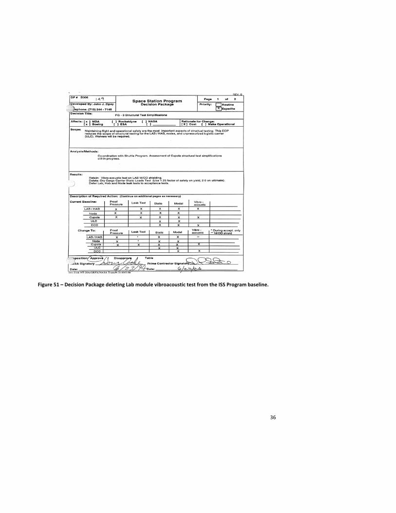
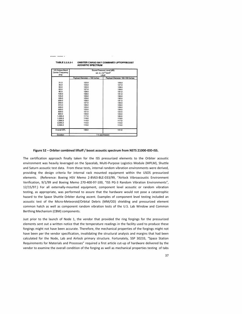
A critical issue to be addressed was the lack of full-scale acoustic testing on the USOS pressurized elements. During the ISS Program rebaselining activity, it was discovered that developing a full-scale, acoustic test capability near MSFC would be cost-prohibitive (Figure 51) [20]. Other acoustic test facilities existed, but the cost and schedule impacts for shipping the Node STA, Common Module STA and the Airlock protoflight article to a distant facility and performing the testing were also perceived to be excessive. All ISS elements were required to be certified to the 141 dB Overall Average Sound Pressure Level environment inside the Orbiter Payload Bay (Figure 52) [21], so a technically acceptable compromise had to be developed.
36
Figure 51 – Decision Package deleting Lab module vibroacoustic test from the ISS Program baseline.
37
Figure 52 – Orbiter combined liftoff / boost acoustic spectrum from NSTS 21000-IDD-ISS.
The certification approach finally taken for the ISS pressurized elements to the Orbiter acoustic environment was heavily leveraged on the Spacelab, Multi-Purpose Logistics Module (MPLM), Shuttle and Saturn acoustic test data. From these tests, internal random vibration environments were derived, providing the design criteria for internal rack mounted equipment within the USOS pressurized elements. (Reference: Boeing HSV Memo 2-8V63-BLE-033/99, “Airlock Vibroacoustic Environment Verification, 9/1/99 and Boeing Memo 270-400-97-100, “ISS PG-3 Random Vibration Environments”, 12/15/97.) For all externally-mounted equipment, component level acoustic or random vibration testing, as appropriate, was performed to assure that the hardware would not pose a catastrophic hazard to the Space Shuttle Orbiter during ascent. Examples of component level testing included an acoustic test of the Micro-Meteoroid/Orbital Debris (MM/OD) shielding and pressurized element common hatch as well as component random vibration tests of the U.S. Lab Window and Common Berthing Mechanism (CBM) components.
Just prior to the launch of Node 1, the vendor that provided the ring forgings for the pressurized elements sent out a written notice that the temperature readings in the facility used to produce these forgings might not have been accurate. Therefore, the mechanical properties of the forgings might not have been per the vendor specification, invalidating the structural analysis and margins that had been calculated for the Node, Lab and Airlock primary structure. Fortunately, SSP 30233, “Space Station Requirements for Materials and Processes” required a first article cut-up of hardware delivered by the vendor to examine the overall condition of the forging as well as mechanical properties testing of tabs
38
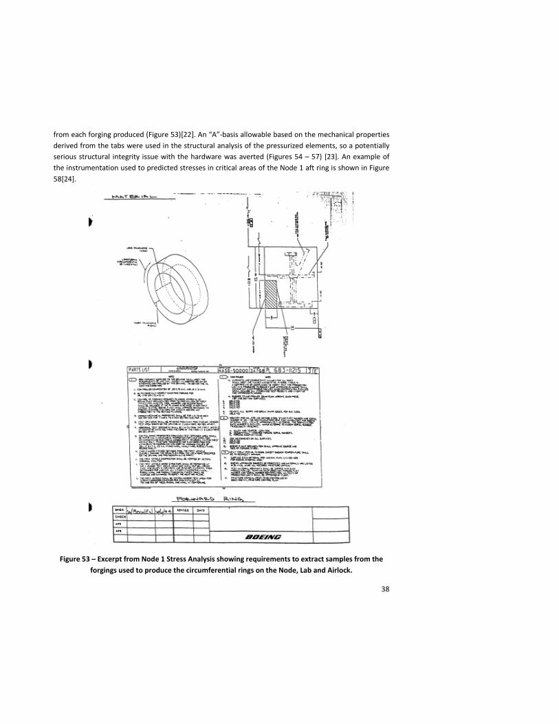
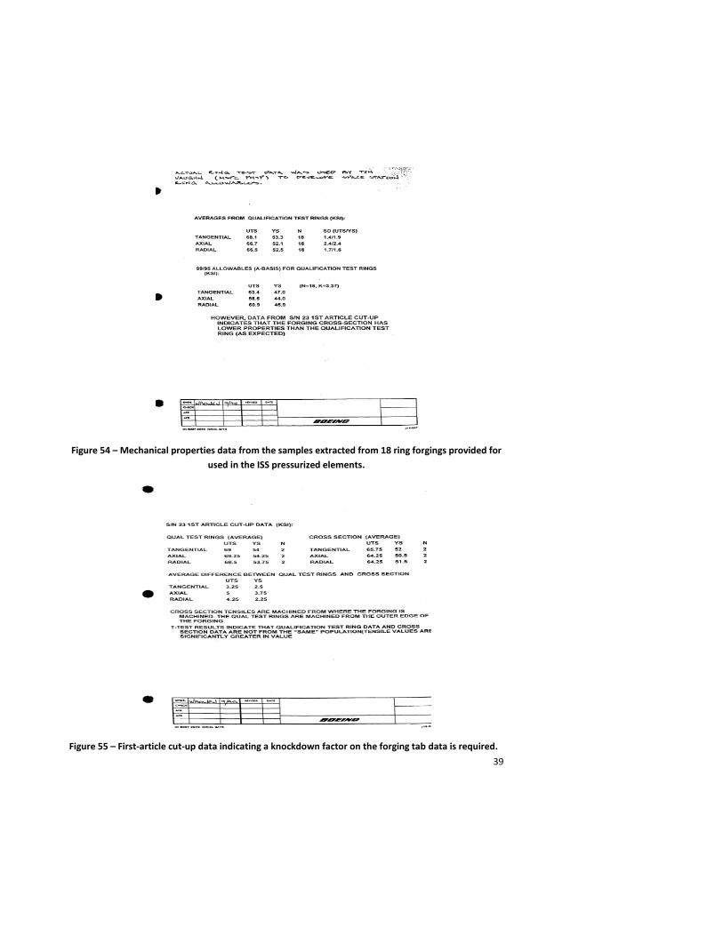
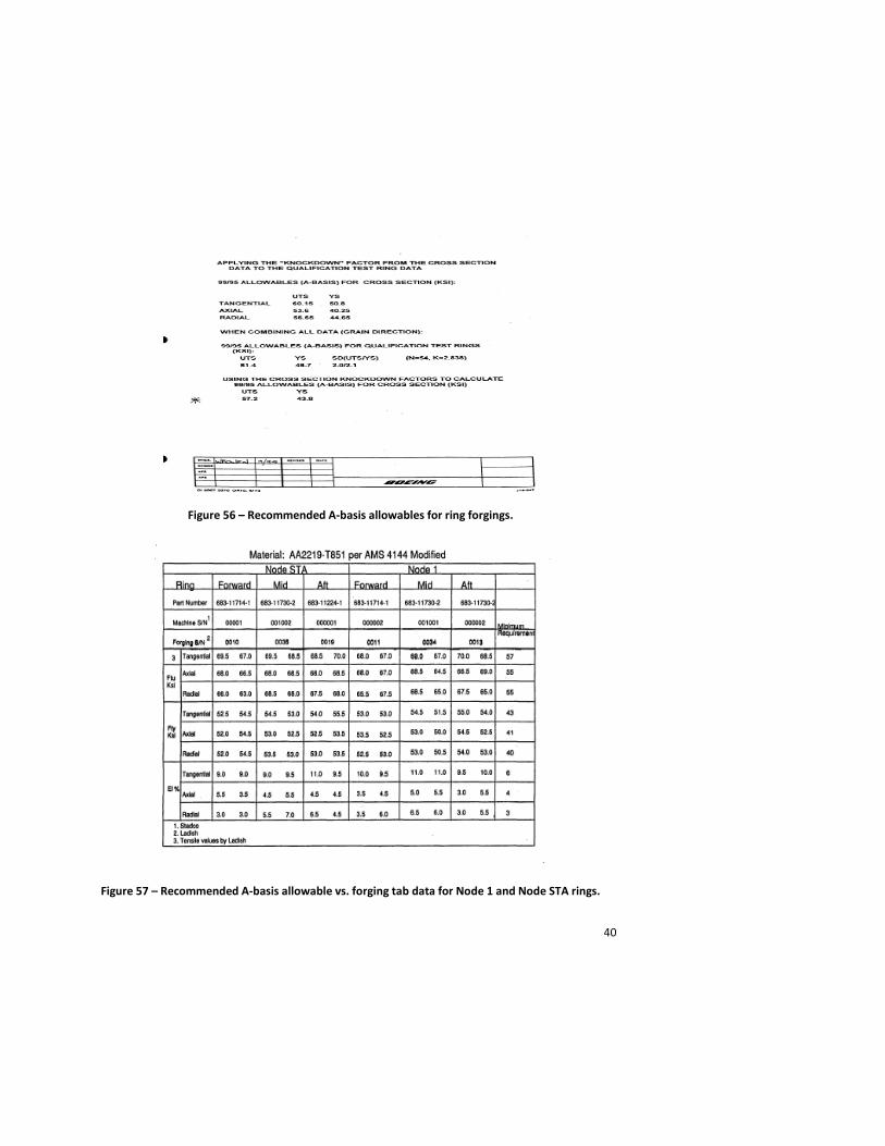
from each forging produced (Figure 53)[22]. An “A”-basis allowable based on the mechanical properties derived from the tabs were used in the structural analysis of the pressurized elements, so a potentially serious structural integrity issue with the hardware was averted (Figures 54 – 57) [23]. An example of the instrumentation used to predicted stresses in critical areas of the Node 1 aft ring is shown in Figure 58[24].
Figure 53 – Excerpt from Node 1 Stress Analysis showing requirements to extract samples from the forgings used to produce the circumferential rings on the Node, Lab and Airlock.
39
Figure 54 – Mechanical properties data from the samples extracted from 18 ring forgings provided for used in the ISS pressurized elements.
Figure 55 – First-article cut-up data indicating a knockdown factor on the forging tab data is required.
40
Figure 56 – Recommended A-basis allowables for ring forgings.
Figure 57 – Recommended A-basis allowable vs. forging tab data for Node 1 and Node STA rings.
41
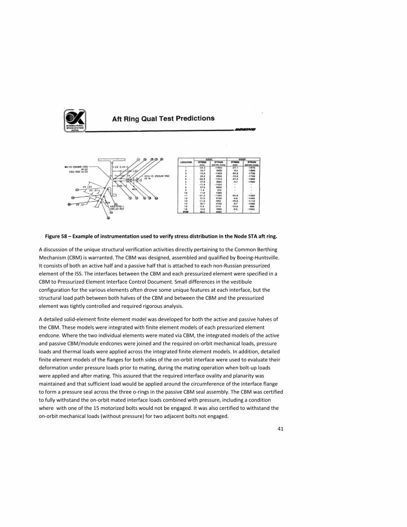
Figure 58 – Example of instrumentation used to verify stress distribution in the Node STA aft ring.
A discussion of the unique structural verification activities directly pertaining to the Common Berthing Mechanism (CBM) is warranted. The CBM was designed, assembled and qualified by Boeing-Huntsville. It consists of both an active half and a passive half that is attached to each non-Russian pressurized element of the ISS. The interfaces between the CBM and each pressurized element were specified in a CBM to Pressurized Element Interface Control Document. Small differences in the vestibule configuration for the various elements often drove some unique features at each interface, but the structural load path between both halves of the CBM and between the CBM and the pressurized element was tightly controlled and required rigorous analysis.
A detailed solid-element finite element model was developed for both the active and passive halves of the CBM. These models were integrated with finite element models of each pressurized element endcone. Where the two individual elements were mated via CBM, the integrated models of the active and passive CBM/module endcones were joined and the required on-orbit mechanical loads, pressure loads and thermal loads were applied across the integrated finite element models. In addition, detailed finite element models of the flanges for both sides of the on-orbit interface were used to evaluate their deformation under pressure loads prior to mating, during the mating operation when bolt-up loads were applied and after mating. This assured that the required interface ovality and planarity was maintained and that sufficient load would be applied around the circumference of the interface flange to form a pressure seal across the three o-rings in the passive CBM seal assembly. The CBM was certified to fully withstand the on-orbit mated interface loads combined with pressure, including a condition where with one of the 15 motorized bolts would not be engaged. It was also certified to withstand the on-orbit mechanical loads (without pressure) for two adjacent bolts not engaged.
42
The CBM was certified for pressure and on-orbit thermally-induced loads combined with flange deflections in the Assembly Level Qualification Test program at MSFC. This rig was located at MSFC and was a full thermal-vacuum qualification test set-up where both halves of the CBM interface were brought together to certify the contact dynamics models, the 16 motorized bolts were engaged and disengaged multiple times, the vestibule was pressurized, both the Shuttle Remote Manipulator System (SRMS) and the Space Station Remote Manipulator System (SSRMS) dynamic responses were simulated and man-in-the loop testing was performed. This rig was essential for the certification of the CBM for both the on-orbit mating operation and structural integrity.
The “Unity” Node with PMAs 1 and 2 attached to it was launched on STS-88 on December 4, 1998 and successfully mated to the FGB on December 6, 1998.
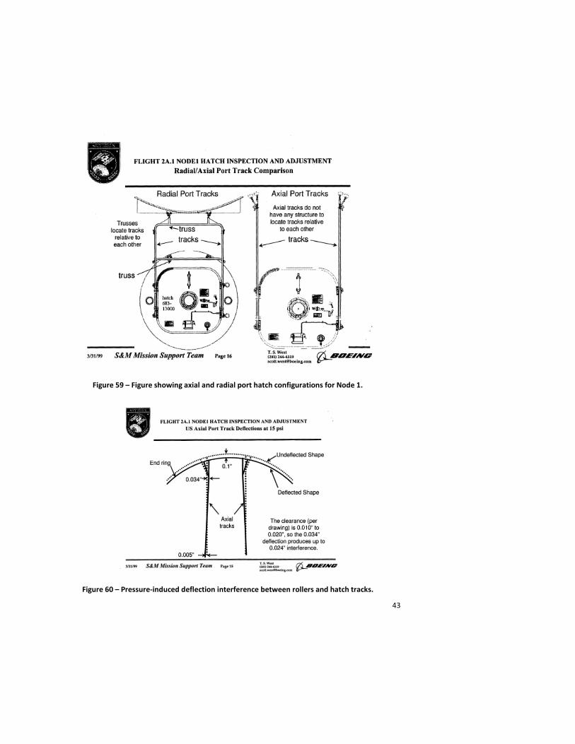
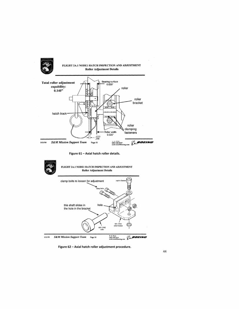
During the first ingress, it was noted that the axial port hatch, when opened, did not travel all of the way up its tracks (Figure 59) [25]. One small detail was missed during Node proof pressure testing and hatch installation. The pressure deflections of the Node endcone could close the existing gap between the hatch rollers and the hatch track causing the hatch to bind in an intermediate position (Figure 60) [26]. After some review of the pressure test data for all of the USOS modules and some tolerance analysis of the hatch and track assembly, a simple modification was made to all axial port hatch rollers still on the ground and the next ISS crew performed this modification on-orbit for the Node 1 hatches to alleviate the problem (Figures 61 and 62)[27].
After three successful EVAs as well as IVA activities inside the nascent space complex, the “Unity” and “Zarya” were activated to form the core of the ISS.
43
Figure 59 – Figure showing axial and radial port hatch configurations for Node 1.
Figure 60 – Pressure-induced deflection interference between rollers and hatch tracks.
44
Figure 61 – Axial hatch roller details.
Figure 62 – Axial hatch roller adjustment procedure.
45
“Destiny” Laboratory
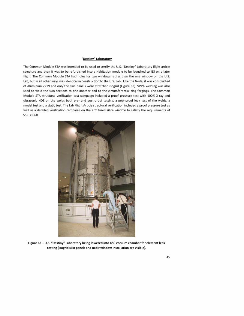
The Common Module STA was intended to be used to certify the U.S. “Destiny” Laboratory flight article structure and then it was to be refurbished into a Habitation module to be launched to ISS on a later flight. The Common Module STA had holes for two windows rather than the one window on the U.S. Lab, but in all other ways was identical in construction to the U.S. Lab. Like the Node, it was constructed of Aluminum 2219 and only the skin panels were stretched isogrid (Figure 63). VPPA welding was also used to weld the skin sections to one another and to the circumferential ring forgings. The Common Module STA structural verification test campaign included a proof pressure test with 100% X-ray and ultrasonic NDE on the welds both pre- and post-proof testing, a post-proof leak test of the welds, a modal test and a static test. The Lab Flight Article structural verification included a proof pressure test as well as a detailed verification campaign on the 20” fused silica window to satisfy the requirements of SSP 30560.
Figure 63 – U.S. “Destiny” Laboratory being lowered into KSC vacuum chamber for element leak testing (Isogrid skin panels and nadir window installation are visible).
46
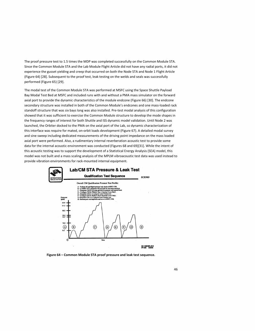
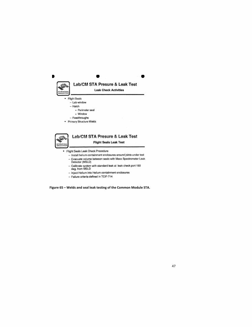
The proof pressure test to 1.5 times the MDP was completed successfully on the Common Module STA. Since the Common Module STA and the Lab Module Flight Article did not have any radial ports, it did not experience the gusset yielding and creep that occurred on both the Node STA and Node 1 Flight Article (Figure 64) [28]. Subsequent to the proof test, leak testing on the welds and seals was successfully performed (Figure 65) [29].
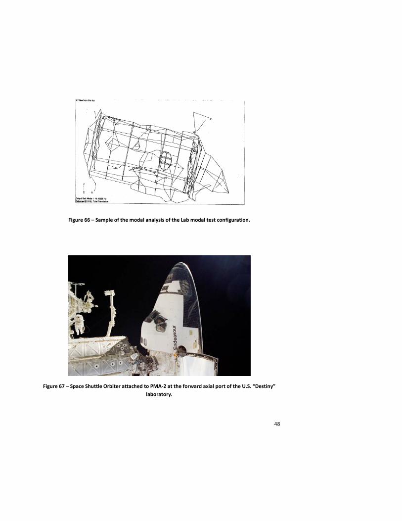
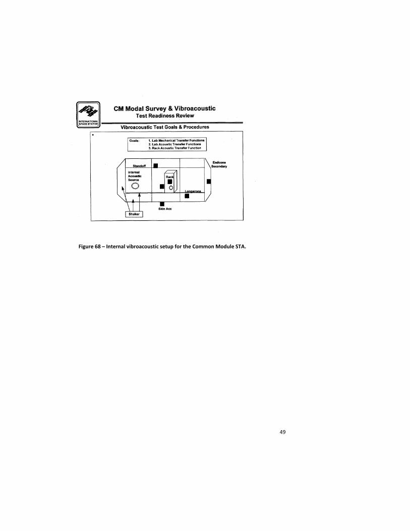
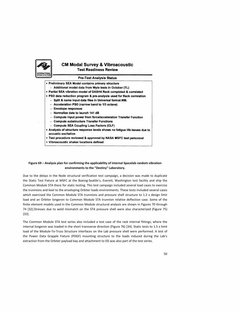
The modal test of the Common Module STA was performed at MSFC using the Space Shuttle Payload Bay Modal Test Bed at MSFC and included runs with and without a PMA mass simulator on the forward axial port to provide the dynamic characteristics of the module endcone (Figure 66) [30]. The endcone secondary structure was installed in both of the Common Module’s endcones and one mass-loaded rack standoff structure that was six bays long was also installed. Pre-test modal analysis of this configuration showed that it was sufficient to exercise the Common Module structure to develop the mode shapes in the frequency ranges of interest for both Shuttle and ISS dynamic model validation. Until Node 2 was launched, the Orbiter docked to the PMA on the axial port of the Lab, so dynamic characterization of this interface was require for mated, on-orbit loads development (Figure 67). A detailed modal survey and sine sweep including dedicated measurements of the driving point impedance on the mass loaded axial port were performed. Also, a rudimentary internal reverberation acoustic test to provide some data for the internal acoustic environment was conducted (Figures 68 and 69)[31]. While the intent of this acoustic testing was to support the development of a Statistical Energy Analysis (SEA) model, this model was not built and a mass scaling analysis of the MPLM vibroacoustic test data was used instead to provide vibration environments for rack-mounted internal equipment.
Figure 64 – Common Module STA proof pressure and leak test sequence.
47
Figure 65 – Welds and seal leak testing of the Common Module STA.
48
Figure 66 – Sample of the modal analysis of the Lab modal test configuration.
Figure 67 – Space Shuttle Orbiter attached to PMA-2 at the forward axial port of the U.S. “Destiny” laboratory.
49
Figure 68 – Internal vibroacoustic setup for the Common Module STA.
50
Figure 69 – Analysis plan for confirming the applicability of internal Spacelab random vibration environments to the “Destiny” Laboratory.
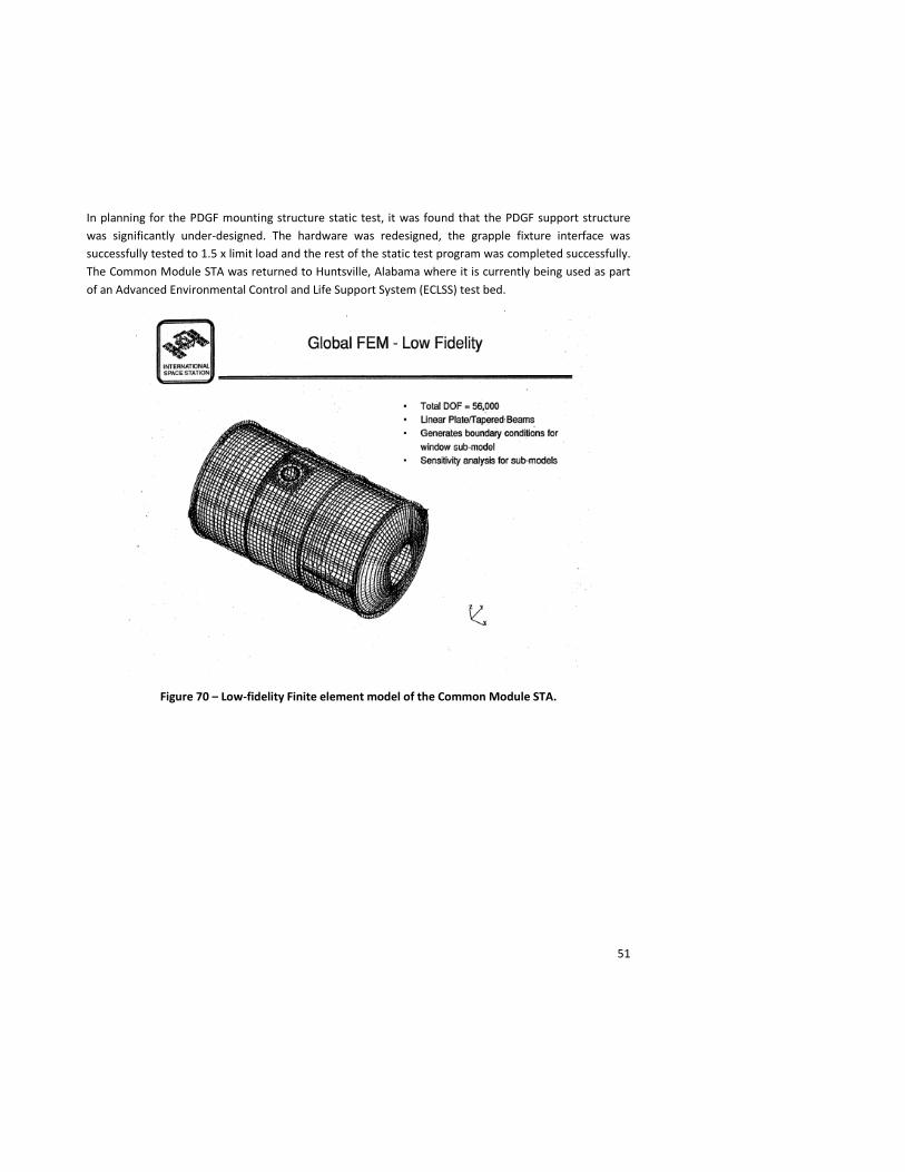
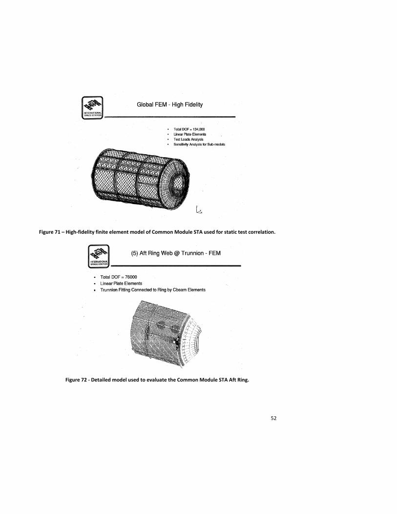
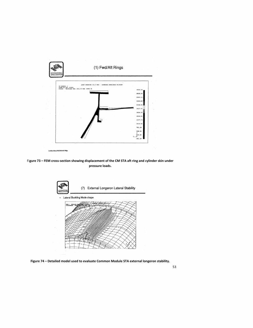
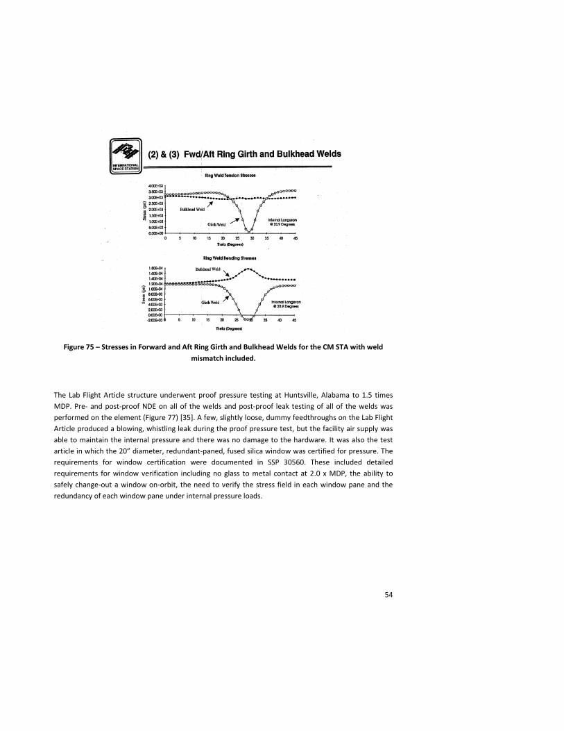
Due to the delays in the Node structural verification test campaign, a decision was made to duplicate the Static Test Fixture at MSFC at the Boeing-Seattle’s, Everett, Washington test facility and ship the Common Module STA there for static testing. This test campaign included several load cases to exercise the trunnions and keel to the enveloping Orbiter loads environments. These tests included several cases which exercised the Common Module STA trunnions and pressure shell structure to 1.2 x design limit load and an Orbiter longeron to Common Module STA trunnion relative deflection case. Some of the finite element models used in the Common Module structural analysis are shown in Figures 70 through 74 [32].Stresses due to weld mismatch on the STA pressure shell were also characterized (Figure 75) [33].
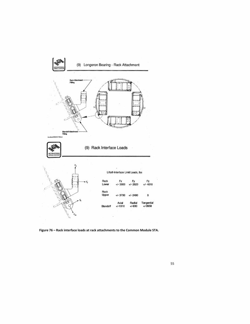
The Common Module STA test series also included a test case of the rack internal fittings, where the internal longeron was loaded in the short transverse direction (Figure 76) [34]. Static tests to 1.5 x limit load of the Module-To-Truss Structure interfaces on the Lab pressure shell were performed. A test of the Power Data Grapple Fixture (PDGF) mounting structure to the loads induced during the Lab’s extraction from the Orbiter payload bay and attachment to ISS was also part of the test series.
51
In planning for the PDGF mounting structure static test, it was found that the PDGF support structure was significantly under-designed. The hardware was redesigned, the grapple fixture interface was successfully tested to 1.5 x limit load and the rest of the static test program was completed successfully. The Common Module STA was returned to Huntsville, Alabama where it is currently being used as part of an Advanced Environmental Control and Life Support System (ECLSS) test bed.
Figure 70 – Low-fidelity Finite element model of the Common Module STA.
52
Figure 71 – High-fidelity finite element model of Common Module STA used for static test correlation.
Figure 72 - Detailed model used to evaluate the Common Module STA Aft Ring.
53
Figure 73 – FEM cross-section showing displacement of the CM STA aft ring and cylinder skin under pressure loads.
Figure 74 – Detailed model used to evaluate Common Module STA external longeron stability.
54
Figure 75 – Stresses in Forward and Aft Ring Girth and Bulkhead Welds for the CM STA with weld mismatch included.
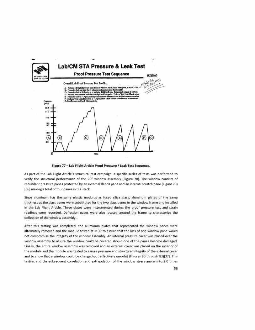
The Lab Flight Article structure underwent proof pressure testing at Huntsville, Alabama to 1.5 times MDP. Pre- and post-proof NDE on all of the welds and post-proof leak testing of all of the welds was performed on the element (Figure 77) [35]. A few, slightly loose, dummy feedthroughs on the Lab Flight Article produced a blowing, whistling leak during the proof pressure test, but the facility air supply was able to maintain the internal pressure and there was no damage to the hardware. It was also the test article in which the 20” diameter, redundant-paned, fused silica window was certified for pressure. The requirements for window certification were documented in SSP 30560. These included detailed requirements for window verification including no glass to metal contact at 2.0 x MDP, the ability to safely change-out a window on-orbit, the need to verify the stress field in each window pane and the redundancy of each window pane under internal pressure loads.
55
Figure 76 – Rack interface loads at rack attachments to the Common Module STA.
56
Figure 77 – Lab Flight Article Proof Pressure / Leak Test Sequence.
As part of the Lab Flight Article’s structural test campaign, a specific series of tests was performed to verify the structural performance of the 20” window assembly (Figure 78). The window consists of redundant pressure panes protected by an external debris pane and an internal scratch pane (Figure 79) [36] making a total of four panes in the stack.
Since aluminum has the same elastic modulus as fused silica glass, aluminum plates of the same thickness as the glass panes were substituted for the two glass panes in the window frame and installed in the Lab Flight Article. These plates were instrumented during the proof pressure test and strain readings were recorded. Deflection gages were also located around the frame to characterize the deflection of the window assembly.
After this testing was completed, the aluminum plates that represented the window panes were alternately removed and the module tested at MDP to assure that the loss of one window pane would not compromise the integrity of the window assembly. An internal pressure cover was placed over the window assembly to assure the window could be covered should one of the panes become damaged. Finally, the entire window assembly was removed and an external cover was placed on the exterior of the module and the module was tested to assure pressure and structural integrity of the external cover and to show that a window could be changed-out effectively on-orbit (Figures 80 through 83)[37]. This testing and the subsequent correlation and extrapolation of the window stress analysis to 2.0 times
57
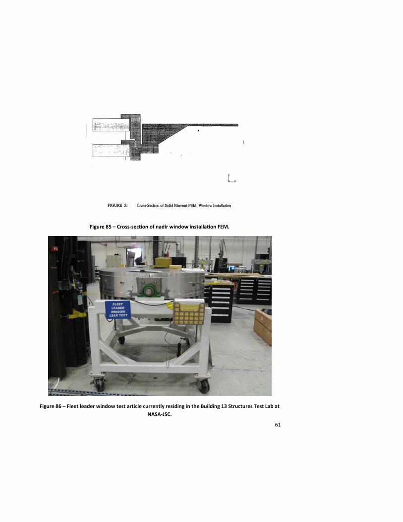
MDP confirmed that the 20”-diameter window would be safe for what was the then-projected to be a 15-year life of the ISS (Figures 84 and 85) [38].
A redundancy test of the 20” redundant pressure pane assembly as also performed. For this test, a full 20” window lab assembly test article with both fused silica panes included was pressurized on one side to 15.2 psid and a weighted stylus was dropped on the outer, redundant pressure pane. This test had to be performed twice, because on the first attempt to shatter the redundant pane, the stylus damaged the window but did not shatter it. The second attempt used a heavier stylus dropped from a greater height. This completely shattered the redundant pane while the primary pressure pane retained its structural and pressure integrity.
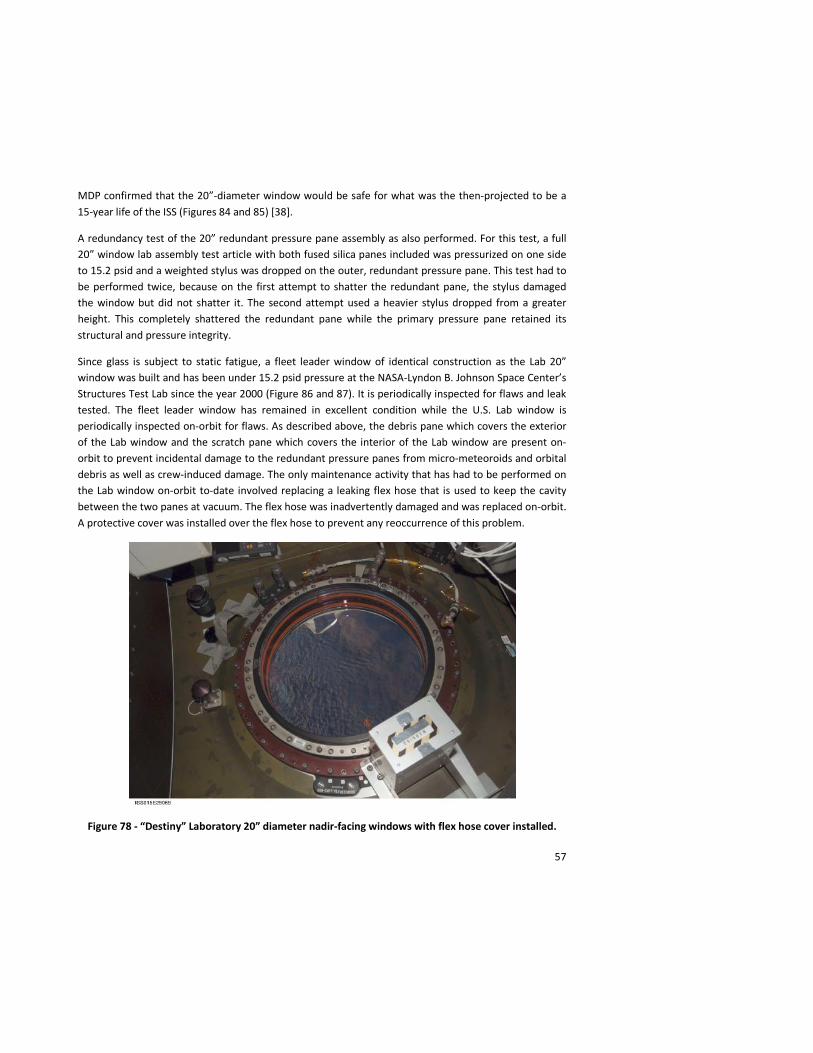
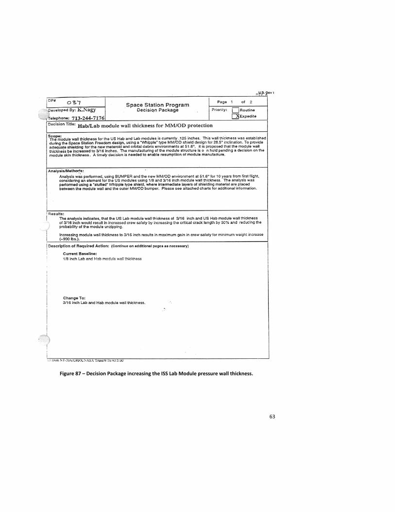
Since glass is subject to static fatigue, a fleet leader window of identical construction as the Lab 20” window was built and has been under 15.2 psid pressure at the NASA-Lyndon B. Johnson Space Center’s Structures Test Lab since the year 2000 (Figure 86 and 87). It is periodically inspected for flaws and leak tested. The fleet leader window has remained in excellent condition while the U.S. Lab window is periodically inspected on-orbit for flaws. As described above, the debris pane which covers the exterior of the Lab window and the scratch pane which covers the interior of the Lab window are present on-orbit to prevent incidental damage to the redundant pressure panes from micro-meteoroids and orbital debris as well as crew-induced damage. The only maintenance activity that has had to be performed on the Lab window on-orbit to-date involved replacing a leaking flex hose that is used to keep the cavity between the two panes at vacuum. The flex hose was inadvertently damaged and was replaced on-orbit. A protective cover was installed over the flex hose to prevent any reoccurrence of this problem.
Figure 78 - “Destiny” Laboratory 20” diameter nadir-facing windows with flex hose cover installed.

58
Figure 79 – Cross-sectional view of the “Destiny” laboratory 20” window installation.
Figure 80 – Proof Pressure nadir window configurations with and without external panes.
59
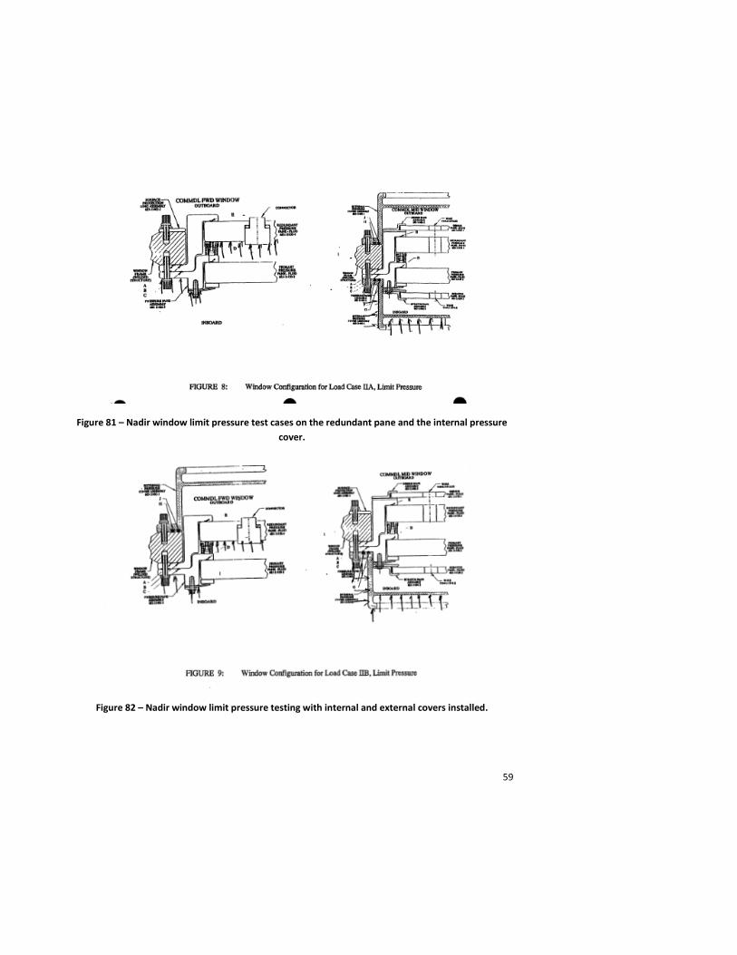
Figure 81 – Nadir window limit pressure test cases on the redundant pane and the internal pressure cover.
Figure 82 – Nadir window limit pressure testing with internal and external covers installed.
60
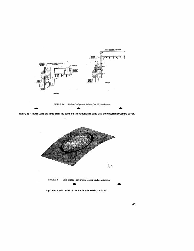
Figure 83 – Nadir window limit pressure tests on the redundant pane and the external pressure cover.
Figure 84 – Solid FEM of the nadir window installation.
61
Figure 85 – Cross-section of nadir window installation FEM.
Figure 86 – Fleet leader window test article currently residing in the Building 13 Structures Test Lab at NASA-JSC.

62
Figure 87 – Close-up of Lab window fleet leader test article glass panes.
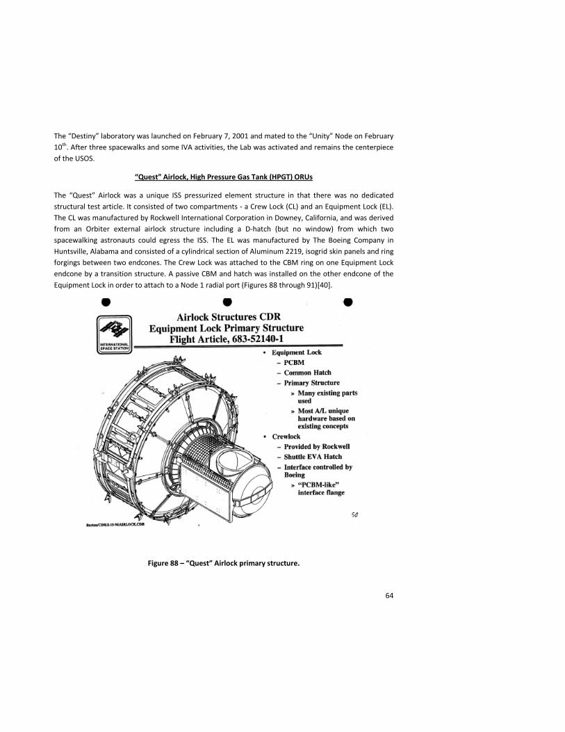
A discussion of the pressure wall thickness for the Lab module is appropriate at this point. The pressure wall thickness for the cylindrical section of the Lab and Airlock (and subsequently extended to the JEM module, Columbus Module and MPLM), was determined not by pressure or mechanical loads, but by risk mitigation of the potential for catastrophic failure of the pressure shell in the event of a penetration by MM/OD (called “unzipping”).
Unzipping was assessed by determining the critical crack length of the Lab module pressure shell over a range of pressure wall thicknesses. Using the probabilistic model of the orbital debris environment, analysts determined that an increase in thickness from 1/8” to 3/16” would increase the critical crack length by 50% and significantly reduce the probability of catastrophic failure of the module structure due to an MM/OD penetration. (The Node pressure wall thickness was well above 3/16” due to the radial port penetrations.) A decision package to increase the Lab module wall thickness was approved by the ISS Program (Figure 87) [39]. Similar assessments on other modules were conducted after the decision package was approved. The Airlock design used a minimum 3/16” pressure wall thickness as did the JEM, MPLM and Columbus Modules.
63
Figure 87 – Decision Package increasing the ISS Lab Module pressure wall thickness.
64
The “Destiny” laboratory was launched on February 7, 2001 and mated to the “Unity” Node on February 10th. After three spacewalks and some IVA activities, the Lab was activated and remains the centerpiece of the USOS.
“Quest” Airlock, High Pressure Gas Tank (HPGT) ORUs
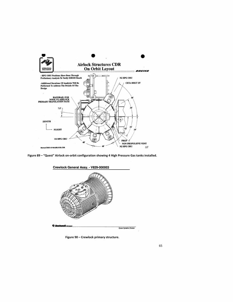
The “Quest” Airlock was a unique ISS pressurized element structure in that there was no dedicated structural test article. It consisted of two compartments - a Crew Lock (CL) and an Equipment Lock (EL). The CL was manufactured by Rockwell International Corporation in Downey, California, and was derived from an Orbiter external airlock structure including a D-hatch (but no window) from which two spacewalking astronauts could egress the ISS. The EL was manufactured by The Boeing Company in Huntsville, Alabama and consisted of a cylindrical section of Aluminum 2219, isogrid skin panels and ring forgings between two endcones. The Crew Lock was attached to the CBM ring on one Equipment Lock endcone by a transition structure. A passive CBM and hatch was installed on the other endcone of the Equipment Lock in order to attach to a Node 1 radial port (Figures 88 through 91)[40].
Figure 88 – “Quest” Airlock primary structure.
65
Figure 89 – “Quest” Airlock on-orbit configuration showing 4 High Pressure Gas tanks installed.
Figure 90 – Crewlock primary structure.
66
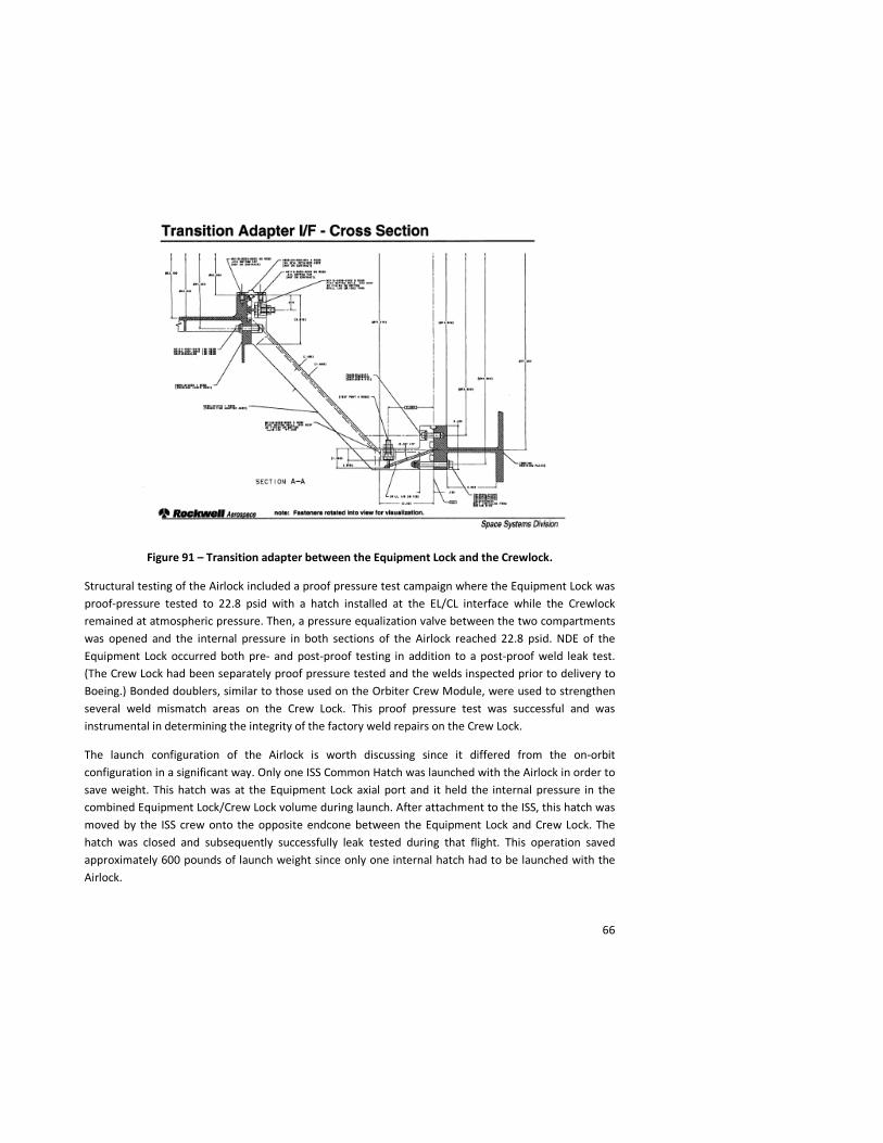
Figure 91 – Transition adapter between the Equipment Lock and the Crewlock.
Structural testing of the Airlock included a proof pressure test campaign where the Equipment Lock was proof-pressure tested to 22.8 psid with a hatch installed at the EL/CL interface while the Crewlock remained at atmospheric pressure. Then, a pressure equalization valve between the two compartments was opened and the internal pressure in both sections of the Airlock reached 22.8 psid. NDE of the Equipment Lock occurred both pre- and post-proof testing in addition to a post-proof weld leak test. (The Crew Lock had been separately proof pressure tested and the welds inspected prior to delivery to Boeing.) Bonded doublers, similar to those used on the Orbiter Crew Module, were used to strengthen several weld mismatch areas on the Crew Lock. This proof pressure test was successful and was instrumental in determining the integrity of the factory weld repairs on the Crew Lock.
The launch configuration of the Airlock is worth discussing since it differed from the on-orbit configuration in a significant way. Only one ISS Common Hatch was launched with the Airlock in order to save weight. This hatch was at the Equipment Lock axial port and it held the internal pressure in the combined Equipment Lock/Crew Lock volume during launch. After attachment to the ISS, this hatch was moved by the ISS crew onto the opposite endcone between the Equipment Lock and Crew Lock. The hatch was closed and subsequently successfully leak tested during that flight. This operation saved approximately 600 pounds of launch weight since only one internal hatch had to be launched with the Airlock.
67
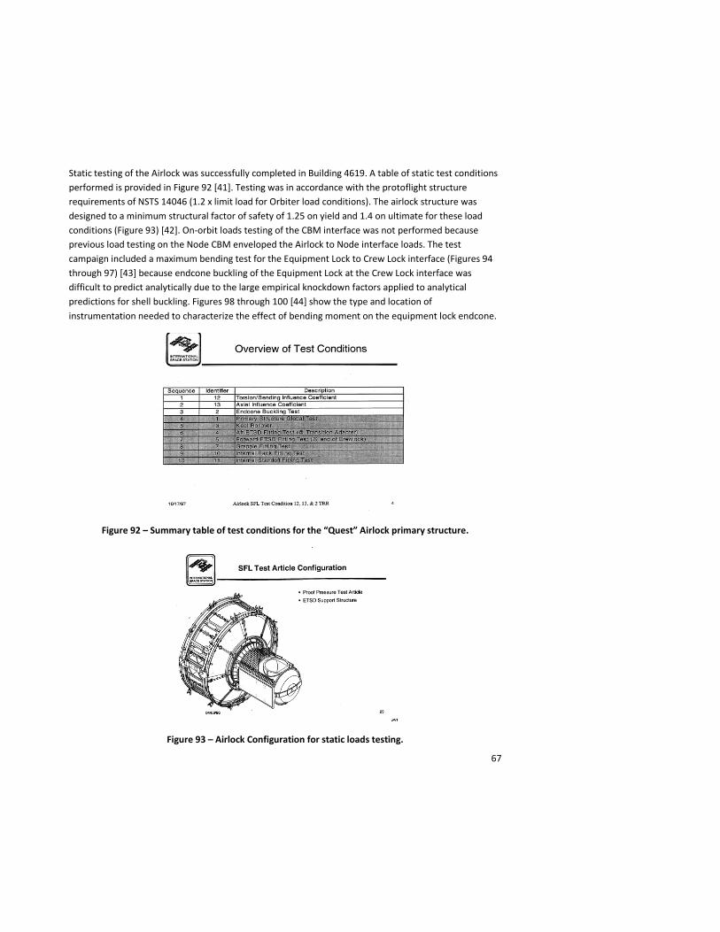
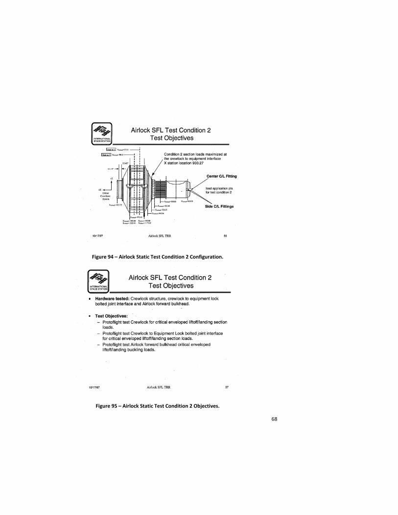
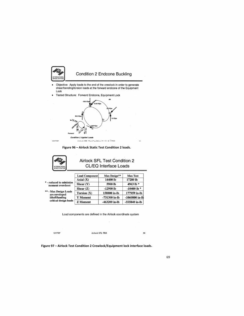
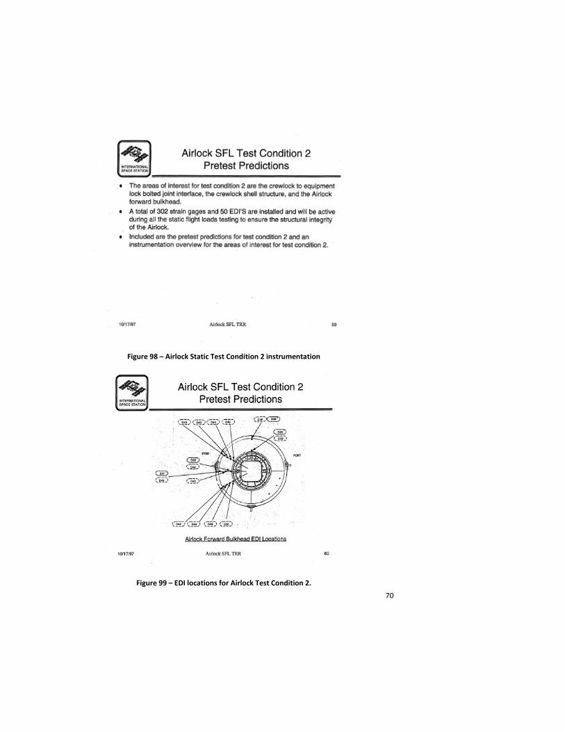
Static testing of the Airlock was successfully completed in Building 4619. A table of static test conditions performed is provided in Figure 92 [41]. Testing was in accordance with the protoflight structure requirements of NSTS 14046 (1.2 x limit load for Orbiter load conditions). The airlock structure was designed to a minimum structural factor of safety of 1.25 on yield and 1.4 on ultimate for these load conditions (Figure 93) [42]. On-orbit loads testing of the CBM interface was not performed because previous load testing on the Node CBM enveloped the Airlock to Node interface loads. The test campaign included a maximum bending test for the Equipment Lock to Crew Lock interface (Figures 94 through 97) [43] because endcone buckling of the Equipment Lock at the Crew Lock interface was difficult to predict analytically due to the large empirical knockdown factors applied to analytical predictions for shell buckling. Figures 98 through 100 [44] show the type and location of instrumentation needed to characterize the effect of bending moment on the equipment lock endcone.
Figure 92 – Summary table of test conditions for the “Quest” Airlock primary structure.
Figure 93 – Airlock Configuration for static loads testing.
68
Figure 94 – Airlock Static Test Condition 2 Configuration.
Figure 95 – Airlock Static Test Condition 2 Objectives.
69
Figure 96 – Airlock Static Test Condition 2 loads.
Figure 97 – Airlock Test Condition 2 Crewlock/Equipment lock interface loads.
70
Figure 98 – Airlock Static Test Condition 2 instrumentation
Figure 99 – EDI locations for Airlock Test Condition 2.

71
Figure 100 – Strain gage locations for Airlock Test Condition 2.
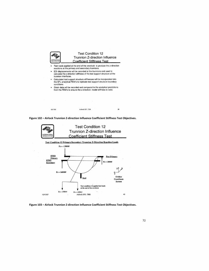
Influence coefficient tests of the trunnion system were significantly important for the Airlock certification due to their minimal spread (Figures 101 – 105) [45]. Influence coefficient tests are primarily used to exercise a structure along a single axis to loads much lower than the certification test loads to assure that the pre-test analytical predictions of load distribution through the structure are accurate. These influence coefficient tests verify the stiffness in the local region of the longeron trunnions and provided the data required to show that the Orbiter launch and landing load cases would not damage the protoflight Airlock structure.
Figure 101 – “Quest” Airlock Trunnion System Configuration.
72
Figure 102 – Airlock Trunnion Z-direction Influence Coefficient Stiffness Test Objectives.
Figure 103 – Airlock Trunnion Z-direction Influence Coefficient Stiffness Test Objectives.
73
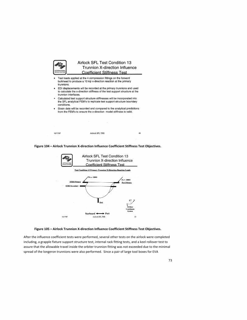
Figure 104 – Airlock Trunnion X-direction Influence Coefficient Stiffness Test Objectives.
Figure 105 – Airlock Trunnion X-direction Influence Coefficient Stiffness Test Objectives.
After the influence coefficient tests were performed, several other tests on the airlock were completed including, a grapple fixture support structure test, internal rack fitting tests, and a keel rollover test to assure that the allowable travel inside the orbiter trunnion fitting was not exceeded due to the minimal spread of the longeron trunnions were also performed. Since a pair of large tool boxes for EVA
74
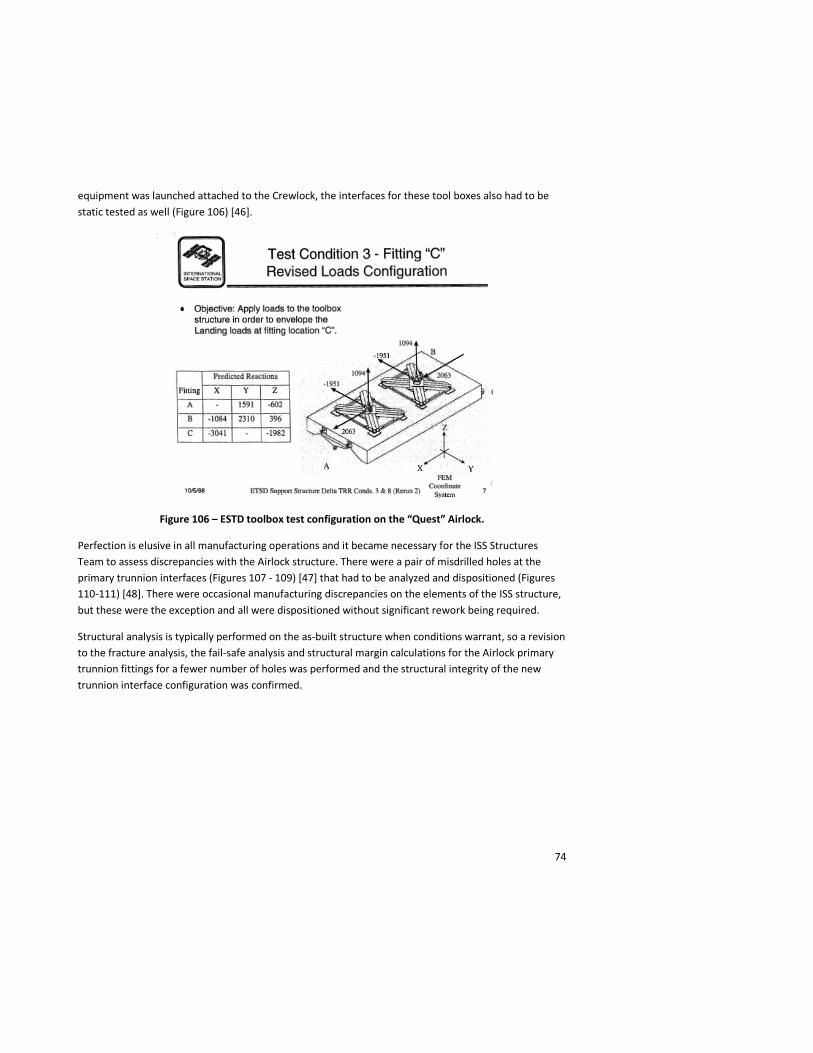
equipment was launched attached to the Crewlock, the interfaces for these tool boxes also had to be static tested as well (Figure 106) [46].
Figure 106 – ESTD toolbox test configuration on the “Quest” Airlock.
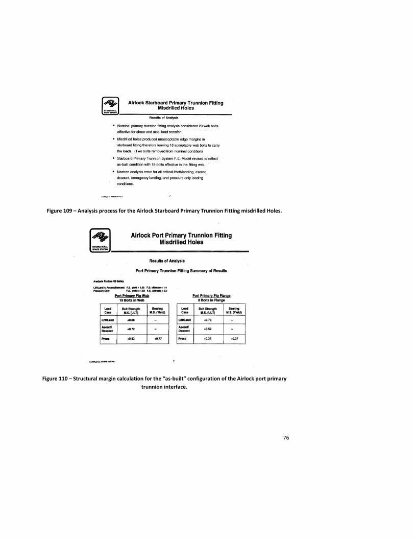
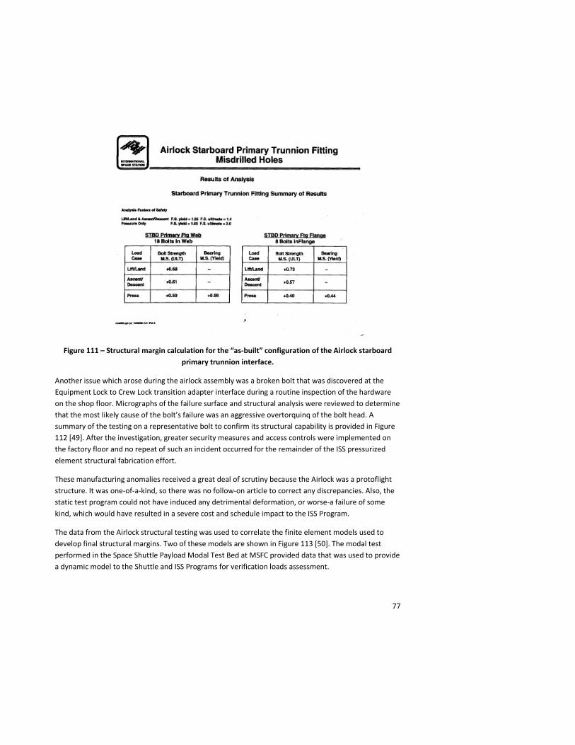
Perfection is elusive in all manufacturing operations and it became necessary for the ISS Structures Team to assess discrepancies with the Airlock structure. There were a pair of misdrilled holes at the primary trunnion interfaces (Figures 107 - 109) [47] that had to be analyzed and dispositioned (Figures 110-111) [48]. There were occasional manufacturing discrepancies on the elements of the ISS structure, but these were the exception and all were dispositioned without significant rework being required.
Structural analysis is typically performed on the as-built structure when conditions warrant, so a revision to the fracture analysis, the fail-safe analysis and structural margin calculations for the Airlock primary trunnion fittings for a fewer number of holes was performed and the structural integrity of the new trunnion interface configuration was confirmed.

75
Figure 107 – Location of misdrilled hole at Airlock primary trunnion fittings.
Figure 108 – Analysis process for the Airlock Port Primary Trunnion Fitting misdrilled holes.
76
Figure 109 – Analysis process for the Airlock Starboard Primary Trunnion Fitting misdrilled Holes.
Figure 110 – Structural margin calculation for the “as-built” configuration of the Airlock port primary trunnion interface.
77
Figure 111 – Structural margin calculation for the “as-built” configuration of the Airlock starboard primary trunnion interface.
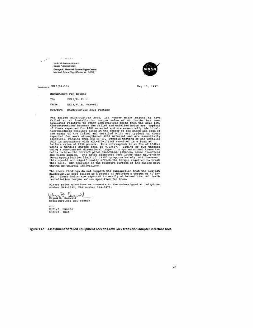
Another issue which arose during the airlock assembly was a broken bolt that was discovered at the Equipment Lock to Crew Lock transition adapter interface during a routine inspection of the hardware on the shop floor. Micrographs of the failure surface and structural analysis were reviewed to determine that the most likely cause of the bolt’s failure was an aggressive overtorquinq of the bolt head. A summary of the testing on a representative bolt to confirm its structural capability is provided in Figure 112 [49]. After the investigation, greater security measures and access controls were implemented on the factory floor and no repeat of such an incident occurred for the remainder of the ISS pressurized element structural fabrication effort.
These manufacturing anomalies received a great deal of scrutiny because the Airlock was a protoflight structure. It was one-of-a-kind, so there was no follow-on article to correct any discrepancies. Also, the static test program could not have induced any detrimental deformation, or worse-a failure of some kind, which would have resulted in a severe cost and schedule impact to the ISS Program.
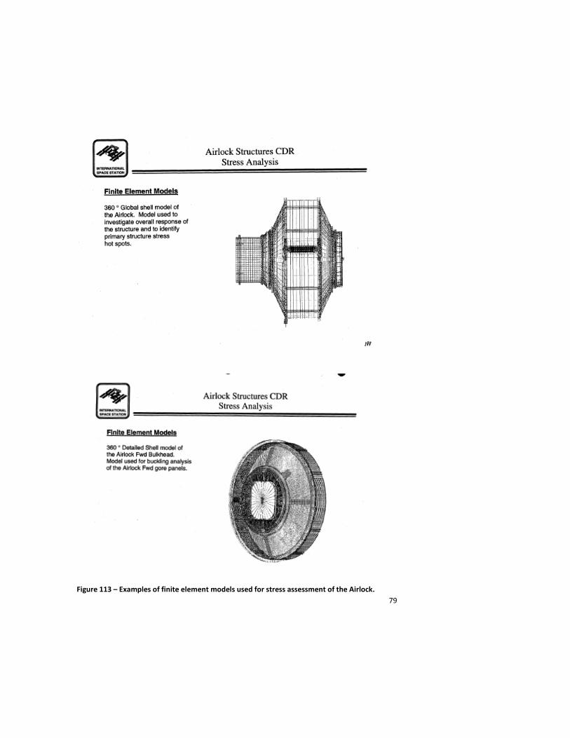
The data from the Airlock structural testing was used to correlate the finite element models used to develop final structural margins. Two of these models are shown in Figure 113 [50]. The modal test performed in the Space Shuttle Payload Modal Test Bed at MSFC provided data that was used to provide a dynamic model to the Shuttle and ISS Programs for verification loads assessment.
78
Figure 112 – Assessment of failed Equipment Lock to Crew Lock transition adapter interface bolt.
79
Figure 113 – Examples of finite element models used for stress assessment of the Airlock.
80
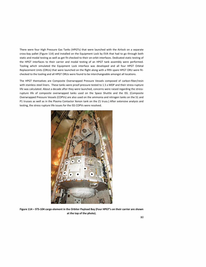
There were four High Pressure Gas Tanks (HPGTs) that were launched with the Airlock on a separate cross-bay pallet (Figure 114) and installed on the Equipment Lock by EVA that had to go through both static and modal testing as well as get fit-checked to their on-orbit interfaces. Dedicated static testing of the HPGT interfaces to their carrier and modal testing of an HPGT tank assembly were performed. Tooling which simulated the Equipment Lock interface was developed and all four HPGT Orbital Replacement Units (ORUs) that were launched on the flight along with a fifth spare HPGT ORU were fit-checked to the tooling and all HPGT ORUs were found to be interchangeable amongst all locations.
The HPGT themselves are Composite Overwrapped Pressure Vessels composed of carbon-fiber/resin with stainless steel liners. These tanks were proof-pressure tested to 1.5 x MDP and their stress-rupture life was calculated. About a decade after they were launched, concerns were raised regarding the stress-rupture life of composite overwrapped tanks used on the Space Shuttle and the ISS. (Composite Overwrapped Pressure Vessels (COPVs) are also used on the ammonia and nitrogen tanks on the S1 and P1 trusses as well as in the Plasma Contactor Xenon tank on the Z1 truss.) After extensive analysis and testing, the stress rupture life issues for the ISS COPVs were resolved.
Figure 114 – STS-104 cargo element in the Orbiter Payload Bay (Four HPGT’s on their carrier are shown at the top of the photo).
81
STS-104 containing the “Quest” Airlock and the High Pressure Gas Tanks was launched on July 12, 2001. The Airlock was installed on ISS on July 15th with the High Pressure Gas Tank installations occurring later in the mission. The final of the three spacewalks on the mission occurred from the “Quest” Airlock. The airlock structure was certified for an estimated 52 EVAs per year over 15 years, so it is anticipated that it will have more than enough structural life for the duration of the ISS program. (As of May, 2011 there have been a total of 93 EVA’s have been performed from the “Quest” Airlock.)
Pressurized Mating Adapters
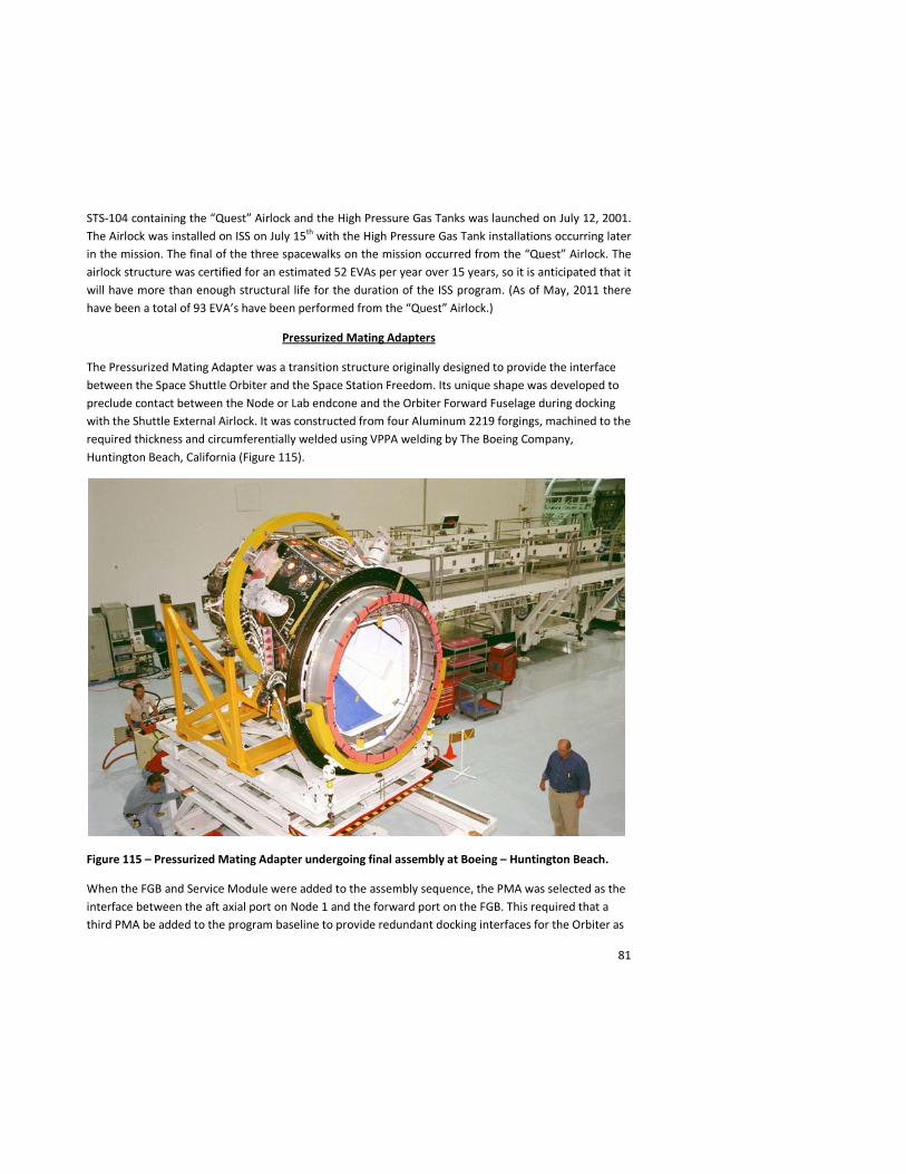
The Pressurized Mating Adapter was a transition structure originally designed to provide the interface between the Space Shuttle Orbiter and the Space Station Freedom. Its unique shape was developed to preclude contact between the Node or Lab endcone and the Orbiter Forward Fuselage during docking with the Shuttle External Airlock. It was constructed from four Aluminum 2219 forgings, machined to the required thickness and circumferentially welded using VPPA welding by The Boeing Company, Huntington Beach, California (Figure 115).
Figure 115 – Pressurized Mating Adapter undergoing final assembly at Boeing – Huntington Beach.
When the FGB and Service Module were added to the assembly sequence, the PMA was selected as the interface between the aft axial port on Node 1 and the forward port on the FGB. This required that a third PMA be added to the program baseline to provide redundant docking interfaces for the Orbiter as
82
well as a permanent interface between the Node 1 and the FGB. The Androgynous Peripheral Attach System (APAS) was added as the interface between both the FGB and the Shuttle Orbiter Docking System and the PMA. The PMA was sized for the pressure and the on-orbit dynamic loads of Orbiter docking and also for the loads at the FGB/PMA interface.
The interface loads between the FGB and the PMA were negotiated between U.S. and Russian engineers and provided to the Boeing Company as structural design criteria in the FGB/PMA Interface Control Document. The maximum design pressure for the PMA was 16.0 pounds per square inch absolute (psia) based on Orbiter Environmental Control and Life Support System (ECLSS) failure modes. An APAS from RSC-Energia and a CBM from Boeing-Huntsville were provided for integration on the opposite ends of the PMA.
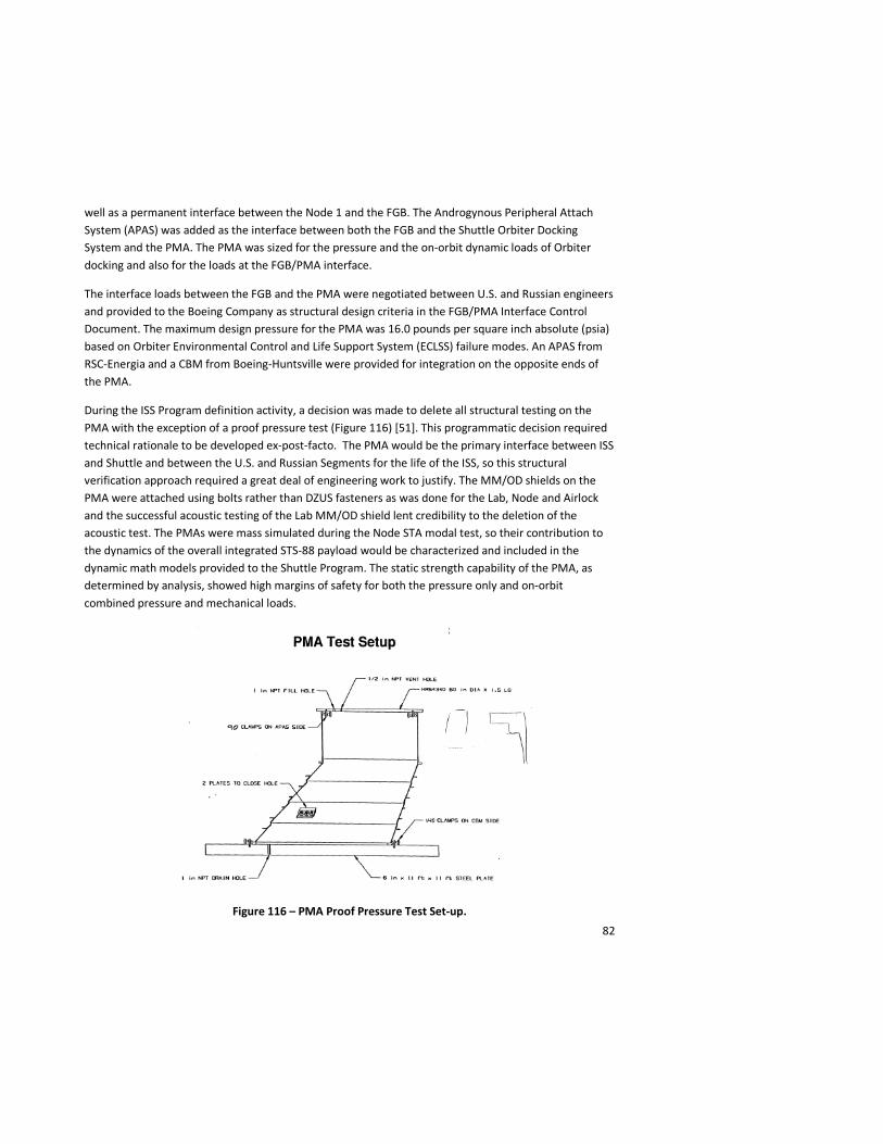
During the ISS Program definition activity, a decision was made to delete all structural testing on the PMA with the exception of a proof pressure test (Figure 116) [51]. This programmatic decision required technical rationale to be developed ex-post-facto. The PMA would be the primary interface between ISS and Shuttle and between the U.S. and Russian Segments for the life of the ISS, so this structural verification approach required a great deal of engineering work to justify. The MM/OD shields on the PMA were attached using bolts rather than DZUS fasteners as was done for the Lab, Node and Airlock and the successful acoustic testing of the Lab MM/OD shield lent credibility to the deletion of the acoustic test. The PMAs were mass simulated during the Node STA modal test, so their contribution to the dynamics of the overall integrated STS-88 payload would be characterized and included in the dynamic math models provided to the Shuttle Program. The static strength capability of the PMA, as determined by analysis, showed high margins of safety for both the pressure only and on-orbit combined pressure and mechanical loads.
Figure 116 – PMA Proof Pressure Test Set-up.
83
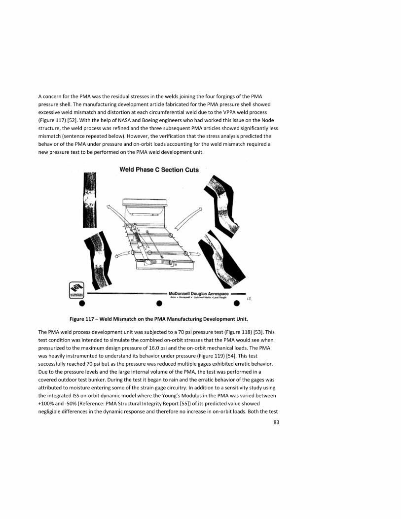
A concern for the PMA was the residual stresses in the welds joining the four forgings of the PMA pressure shell. The manufacturing development article fabricated for the PMA pressure shell showed excessive weld mismatch and distortion at each circumferential weld due to the VPPA weld process (Figure 117) [52]. With the help of NASA and Boeing engineers who had worked this issue on the Node structure, the weld process was refined and the three subsequent PMA articles showed significantly less mismatch (sentence repeated below). However, the verification that the stress analysis predicted the behavior of the PMA under pressure and on-orbit loads accounting for the weld mismatch required a new pressure test to be performed on the PMA weld development unit.
Figure 117 – Weld Mismatch on the PMA Manufacturing Development Unit.
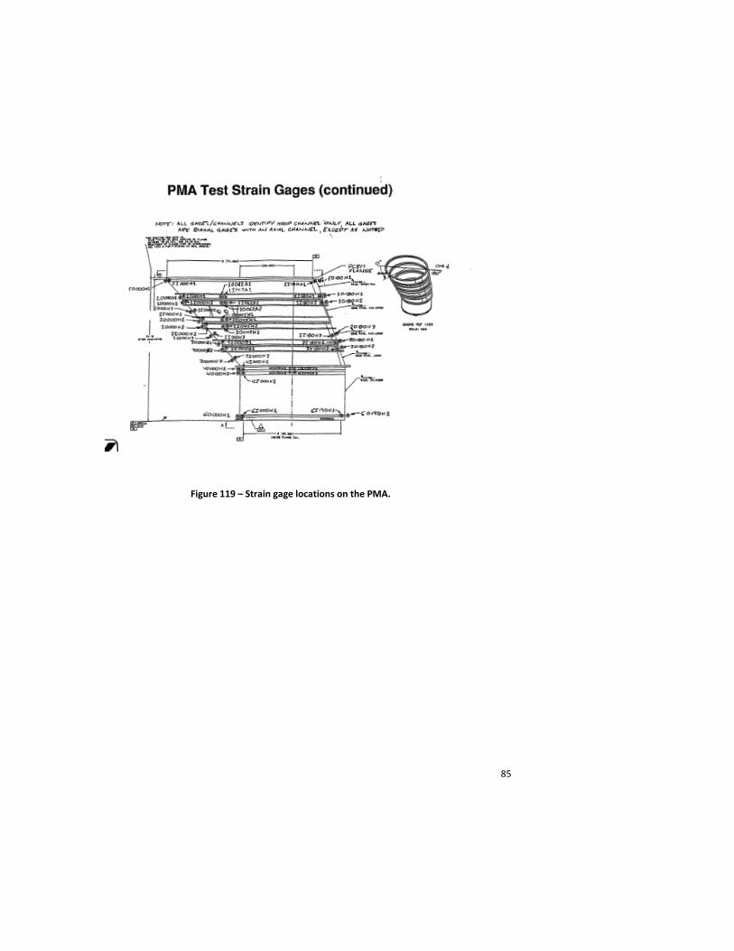
The PMA weld process development unit was subjected to a 70 psi pressure test (Figure 118) [53]. This test condition was intended to simulate the combined on-orbit stresses that the PMA would see when pressurized to the maximum design pressure of 16.0 psi and the on-orbit mechanical loads. The PMA was heavily instrumented to understand its behavior under pressure (Figure 119) [54]. This test successfully reached 70 psi but as the pressure was reduced multiple gages exhibited erratic behavior. Due to the pressure levels and the large internal volume of the PMA, the test was performed in a covered outdoor test bunker. During the test it began to rain and the erratic behavior of the gages was attributed to moisture entering some of the strain gage circuitry. In addition to a sensitivity study using the integrated ISS on-orbit dynamic model where the Young’s Modulus in the PMA was varied between +100% and -50% (Reference: PMA Structural Integrity Report [55]) of its predicted value showed negligible differences in the dynamic response and therefore no increase in on-orbit loads. Both the test
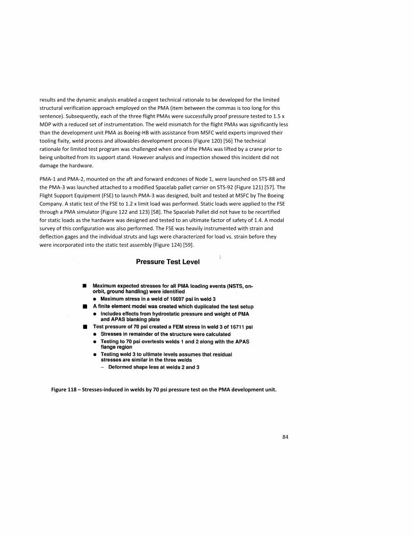
84
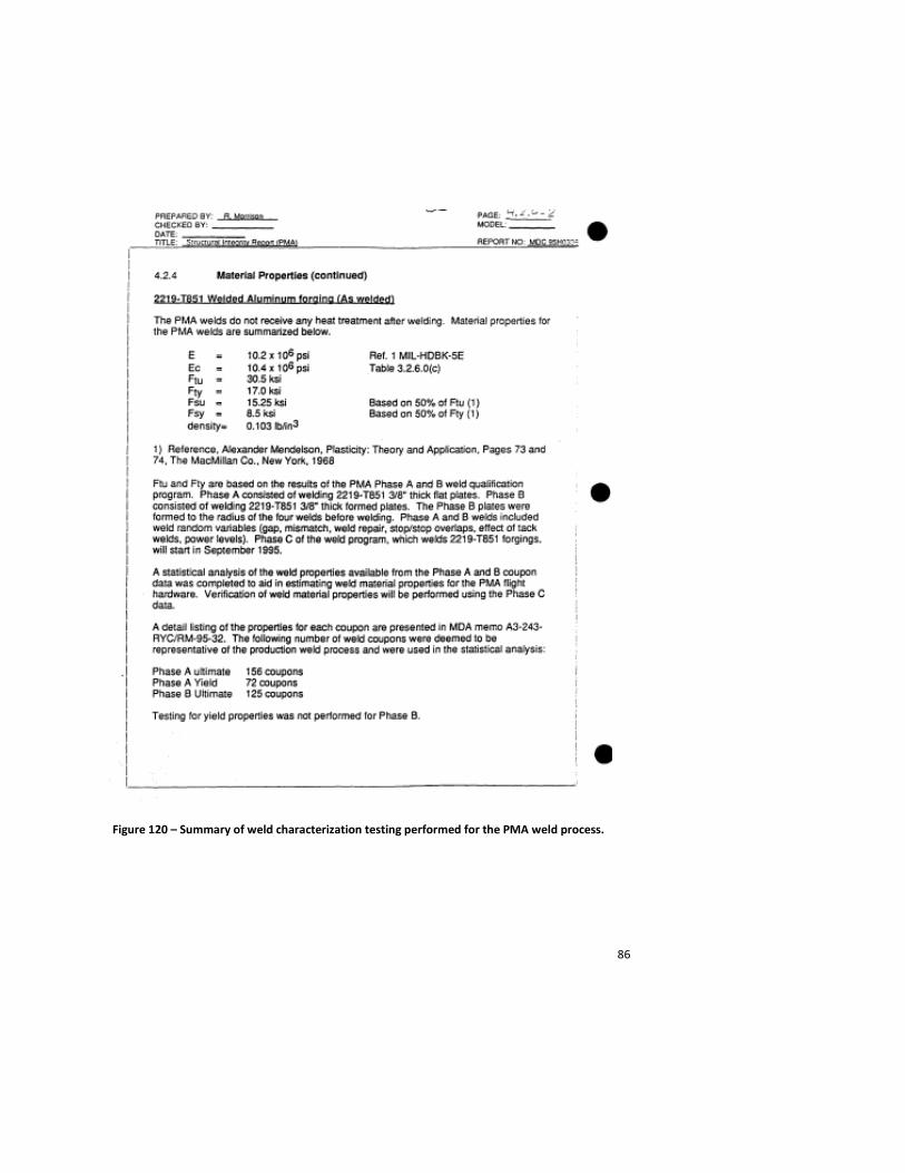
results and the dynamic analysis enabled a cogent technical rationale to be developed for the limited structural verification approach employed on the PMA (item between the commas is too long for this sentence). Subsequently, each of the three flight PMAs were successfully proof pressure tested to 1.5 x MDP with a reduced set of instrumentation. The weld mismatch for the flight PMAs was significantly less than the development unit PMA as Boeing-HB with assistance from MSFC weld experts improved their tooling fixity, weld process and allowables development process (Figure 120) [56] The technical rationale for limited test program was challenged when one of the PMAs was lifted by a crane prior to being unbolted from its support stand. However analysis and inspection showed this incident did not damage the hardware.
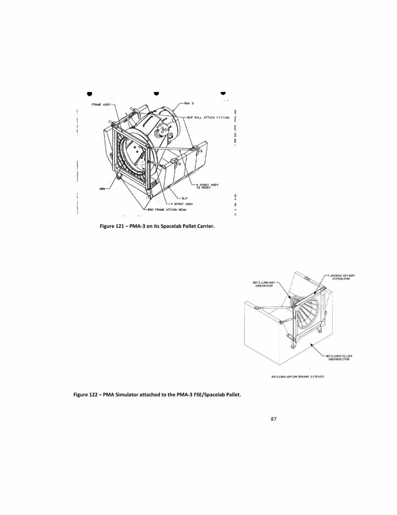
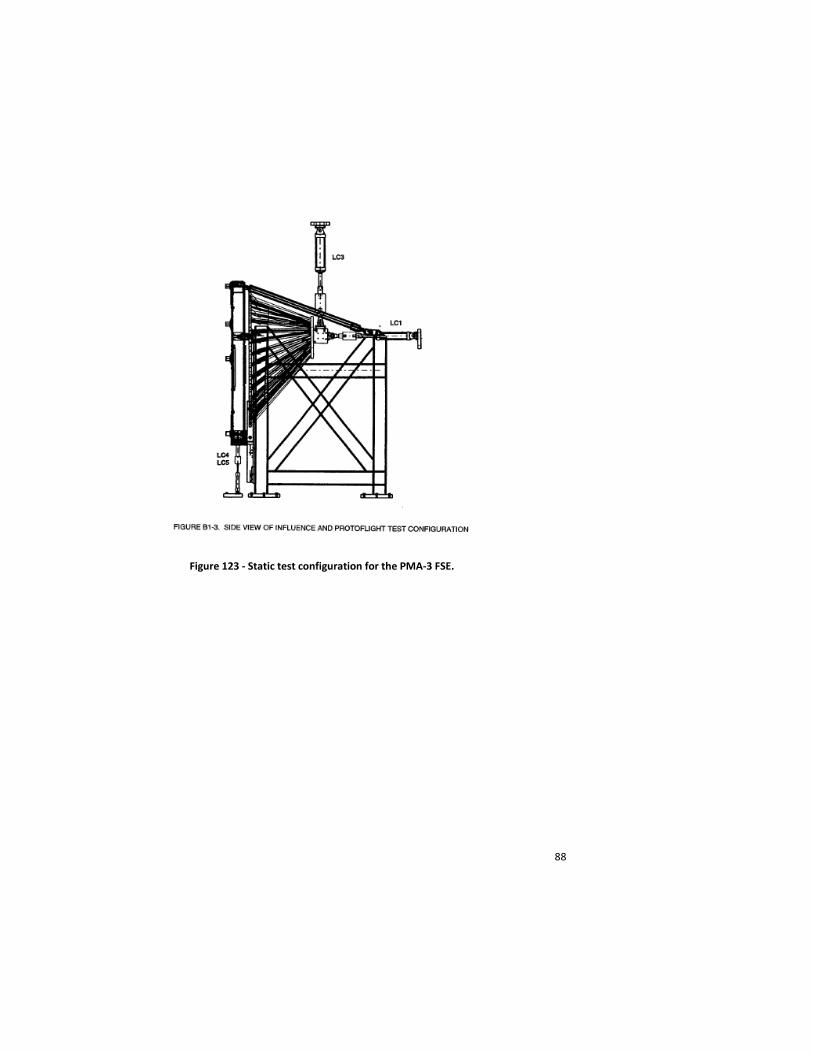
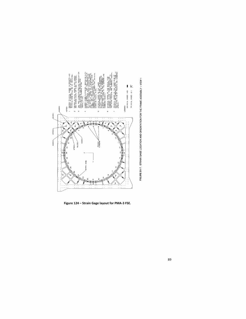
PMA-1 and PMA-2, mounted on the aft and forward endcones of Node 1, were launched on STS-88 and the PMA-3 was launched attached to a modified Spacelab pallet carrier on STS-92 (Figure 121) [57]. The Flight Support Equipment (FSE) to launch PMA-3 was designed, built and tested at MSFC by The Boeing Company. A static test of the FSE to 1.2 x limit load was performed. Static loads were applied to the FSE through a PMA simulator (Figure 122 and 123) [58]. The Spacelab Pallet did not have to be recertified for static loads as the hardware was designed and tested to an ultimate factor of safety of 1.4. A modal survey of this configuration was also performed. The FSE was heavily instrumented with strain and deflection gages and the individual struts and lugs were characterized for load vs. strain before they were incorporated into the static test assembly (Figure 124) [59].
Figure 118 – Stresses-induced in welds by 70 psi pressure test on the PMA development unit.
85
Figure 119 – Strain gage locations on the PMA.
86
Figure 120 – Summary of weld characterization testing performed for the PMA weld process.
87
Figure 121 – PMA-3 on its Spacelab Pallet Carrier.
Figure 122 – PMA Simulator attached to the PMA-3 FSE/Spacelab Pallet.
88
Figure 123 - Static test configuration for the PMA-3 FSE.
89
Figure 124 – Strain Gage layout for PMA-3 FSE.
90
Node 2
With the decision by the ISS Program for the European Space Agency to provide both Node 2 and Node 3, the structural design of these elements was no longer common with that of Node 1 so a new structural verification test campaign needed to be developed. The Node 2/3 structural design was based on the Multi-Purpose Logistics Module (MPLM) design, so these two nodes were longer than Node 1. Consequently, the mass, trunnion spacing and on-orbit loads would result in entirely new launch and on-orbit loading environments beyond what the Node 1 was certified to. It was ESA’s responsibility to certify the Node 2/3 structures to the new loads requirements. Both Node 2 and Node 3 were designed, manufactured and tested by Thales Alenia Space Italy. The primary structure was constructed from Aluminum 2219. The radial port design was based on drawings supplied by The Boeing Company. VPPA welding was used to join the various segments.
The structural verification approach for Node 2/3 differed in several significant ways from Node 1. First of all, there was no complete module structure used as a static test article. A simulator, consisting of two adjacent radial ports and an axial port that were stiffened to represent the Node 2 structure, was used for static testing. Pressure domes were installed over each port. Pressure testing to 2.0 x MDP and combined pressure and mechanical loads testing to 1.5 x (pressure + mechanical loads) was performed on the Node 2/3 STA (but you just said there was no STA). (There were also a few cases where the hardware was critical for on-orbit mechanical loads only. That hardware was tested to 1.5 x limit mechanical loads.) A proof pressure test was performed on both flight articles and CBM radial port flange displacements were measured during this test to confirm they were within their certified limits. Post-proof test NDE was only performed on the welds of Node 3 (per ECP170). Modal testing was performed on the Node 2 flight article.
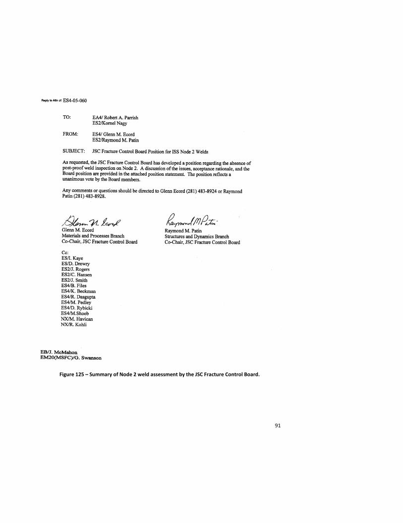
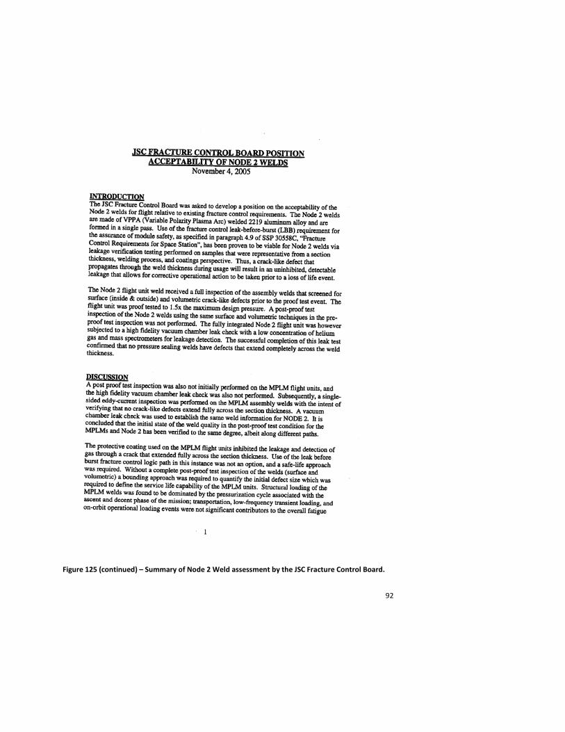
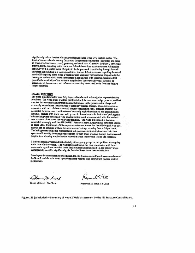
The structural strength and acoustic certification for launch in the Shuttle Orbiter payload bay for Node 2/3 also leveraged on the MPLM design, where an ultimate loads test to 1.4 x limit load and an acoustic test to the 141 decibel (dB) Overall Acoustic Sound Pressure Level (OASPL) were performed on a dedicated MPLM test article in Toulouse, France. The Meteoroid/Debris Panels (MDPS) on the MPLM were certified by similarity and component level ultimate load tests on the trunnion systems were used to certify the Node structure to the launch loads. This overall structural verification approach received a great deal of scrutiny from all of the stakeholders. One issue that did arise was the lack of post-proof test NDE on the welds of the Node 2 structure. An element level leak test in the Kennedy Space Center Operations and Checkout Building vacuum chamber for Node 2 and a one atmosphere delta-pressure helium accumulation test for Node 3 alleviated any leakage or structural integrity concerns with the welds on the hardware (Figure 125) [60].
The Node 2, dubbed “Harmony”, was launched on October 23, 2007 and was attached to the “Destiny” lab on November 14th. It later became the central hub for the attachment of the “Kibo” Japanese Experiment Module, “Columbus” Attached Pressurized Module and PMA-2. It also accepts both the MPLM and the H-II Transfer Vehicle (HTV), operated by the Japanese Aerospace Exploration Agency (JAXA) on its nadir port.
91
Figure 125 – Summary of Node 2 weld assessment by the JSC Fracture Control Board.
92
Figure 125 (continued) – Summary of Node 2 Weld assessment by the JSC Fracture Control Board.

93
Figure 125 (continued) – Summary of Node 2 Weld assessment by the JSC Fracture Control Board.
94
Figure 125 (concluded) – Summary of Node 2 Weld assessment by the JSC Fracture Control Board.
95
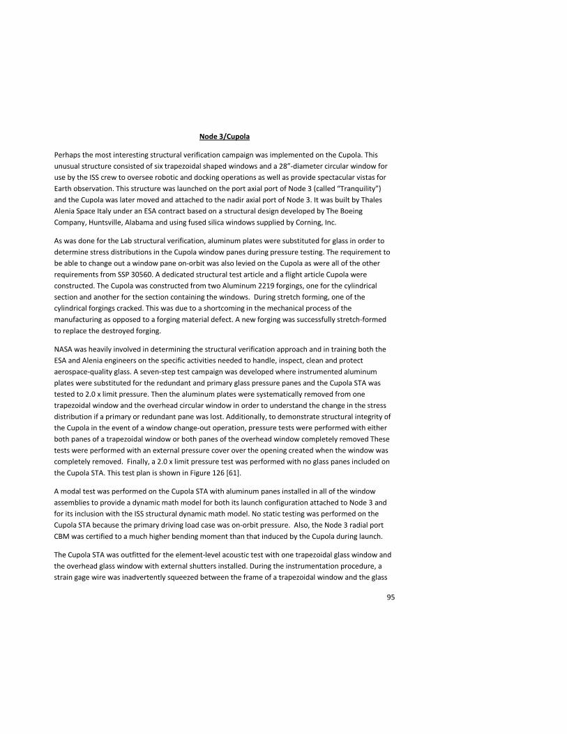
Node 3/Cupola
Perhaps the most interesting structural verification campaign was implemented on the Cupola. This unusual structure consisted of six trapezoidal shaped windows and a 28”-diameter circular window for use by the ISS crew to oversee robotic and docking operations as well as provide spectacular vistas for Earth observation. This structure was launched on the port axial port of Node 3 (called “Tranquility”) and the Cupola was later moved and attached to the nadir axial port of Node 3. It was built by Thales Alenia Space Italy under an ESA contract based on a structural design developed by The Boeing Company, Huntsville, Alabama and using fused silica windows supplied by Corning, Inc.
As was done for the Lab structural verification, aluminum plates were substituted for glass in order to determine stress distributions in the Cupola window panes during pressure testing. The requirement to be able to change out a window pane on-orbit was also levied on the Cupola as were all of the other requirements from SSP 30560. A dedicated structural test article and a flight article Cupola were constructed. The Cupola was constructed from two Aluminum 2219 forgings, one for the cylindrical section and another for the section containing the windows. During stretch forming, one of the cylindrical forgings cracked. This was due to a shortcoming in the mechanical process of the manufacturing as opposed to a forging material defect. A new forging was successfully stretch-formed to replace the destroyed forging.
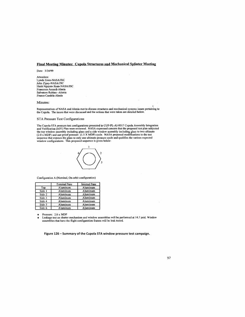
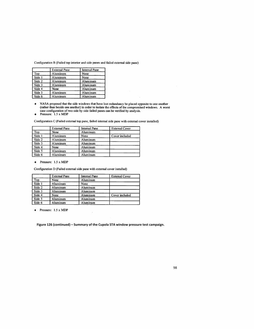
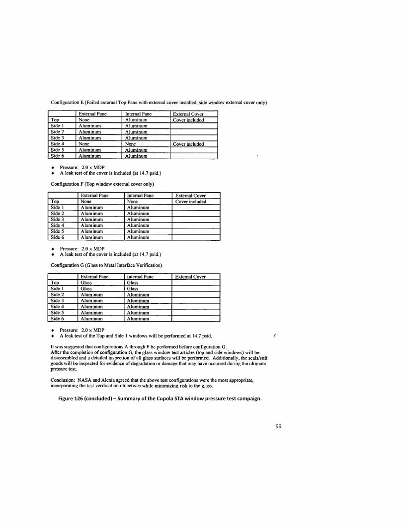
NASA was heavily involved in determining the structural verification approach and in training both the ESA and Alenia engineers on the specific activities needed to handle, inspect, clean and protect aerospace-quality glass. A seven-step test campaign was developed where instrumented aluminum plates were substituted for the redundant and primary glass pressure panes and the Cupola STA was tested to 2.0 x limit pressure. Then the aluminum plates were systematically removed from one trapezoidal window and the overhead circular window in order to understand the change in the stress distribution if a primary or redundant pane was lost. Additionally, to demonstrate structural integrity of the Cupola in the event of a window change-out operation, pressure tests were performed with either both panes of a trapezoidal window or both panes of the overhead window completely removed These tests were performed with an external pressure cover over the opening created when the window was completely removed. Finally, a 2.0 x limit pressure test was performed with no glass panes included on the Cupola STA. This test plan is shown in Figure 126 [61].
A modal test was performed on the Cupola STA with aluminum panes installed in all of the window assemblies to provide a dynamic math model for both its launch configuration attached to Node 3 and for its inclusion with the ISS structural dynamic math model. No static testing was performed on the Cupola STA because the primary driving load case was on-orbit pressure. Also, the Node 3 radial port CBM was certified to a much higher bending moment than that induced by the Cupola during launch.
The Cupola STA was outfitted for the element-level acoustic test with one trapezoidal glass window and the overhead glass window with external shutters installed. During the instrumentation procedure, a strain gage wire was inadvertently squeezed between the frame of a trapezoidal window and the glass
96
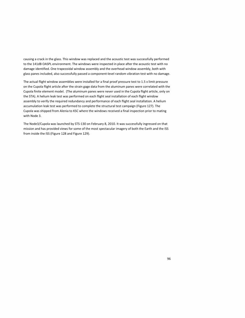
causing a crack in the glass. This window was replaced and the acoustic test was successfully performed to the 141dB OASPL environment. The windows were inspected in place after the acoustic test with no damage identified. One trapezoidal window assembly and the overhead window assembly, both with glass panes included, also successfully passed a component-level random vibration test with no damage.
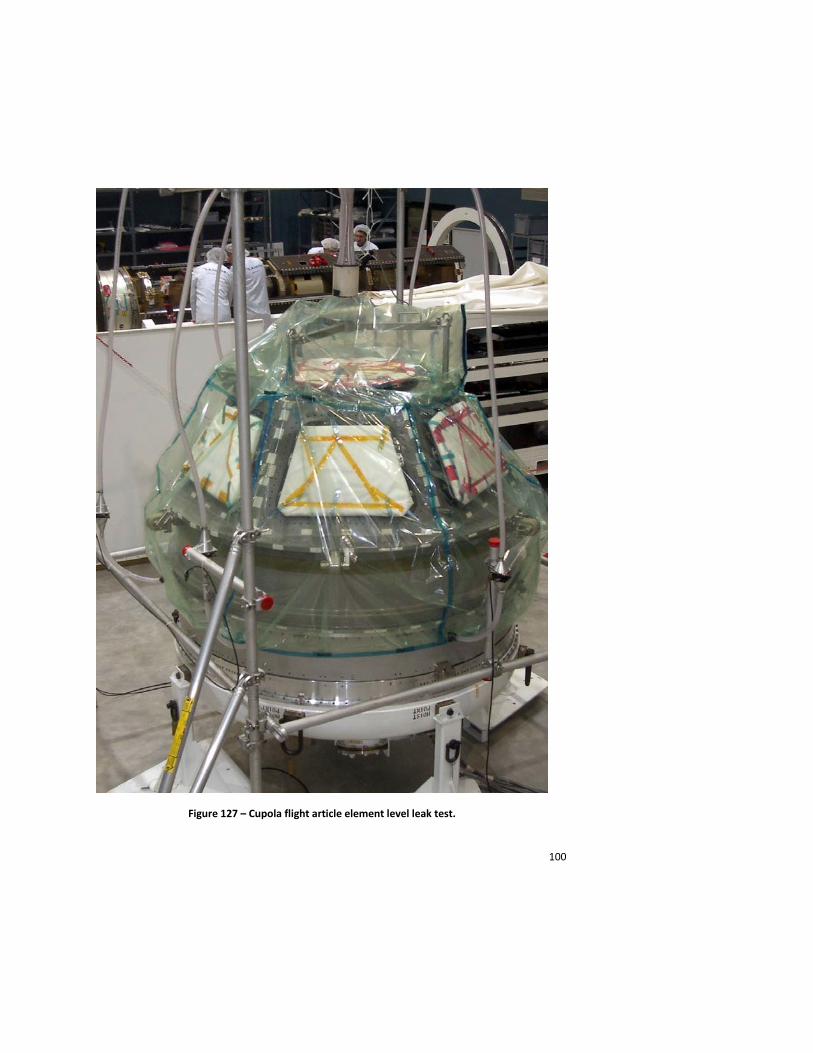
The actual flight window assemblies were installed for a final proof pressure test to 1.5 x limit pressure on the Cupola flight article after the strain gage data from the aluminum panes were correlated with the Cupola finite element model. (The aluminum panes were never used in the Cupola flight article, only on the STA). A helium leak test was performed on each flight seal installation of each flight window assembly to verify the required redundancy and performance of each flight seal installation. A helium accumulation leak test was performed to complete the structural test campaign (Figure 127). The Cupola was shipped from Alenia to KSC where the windows received a final inspection prior to mating with Node 3.
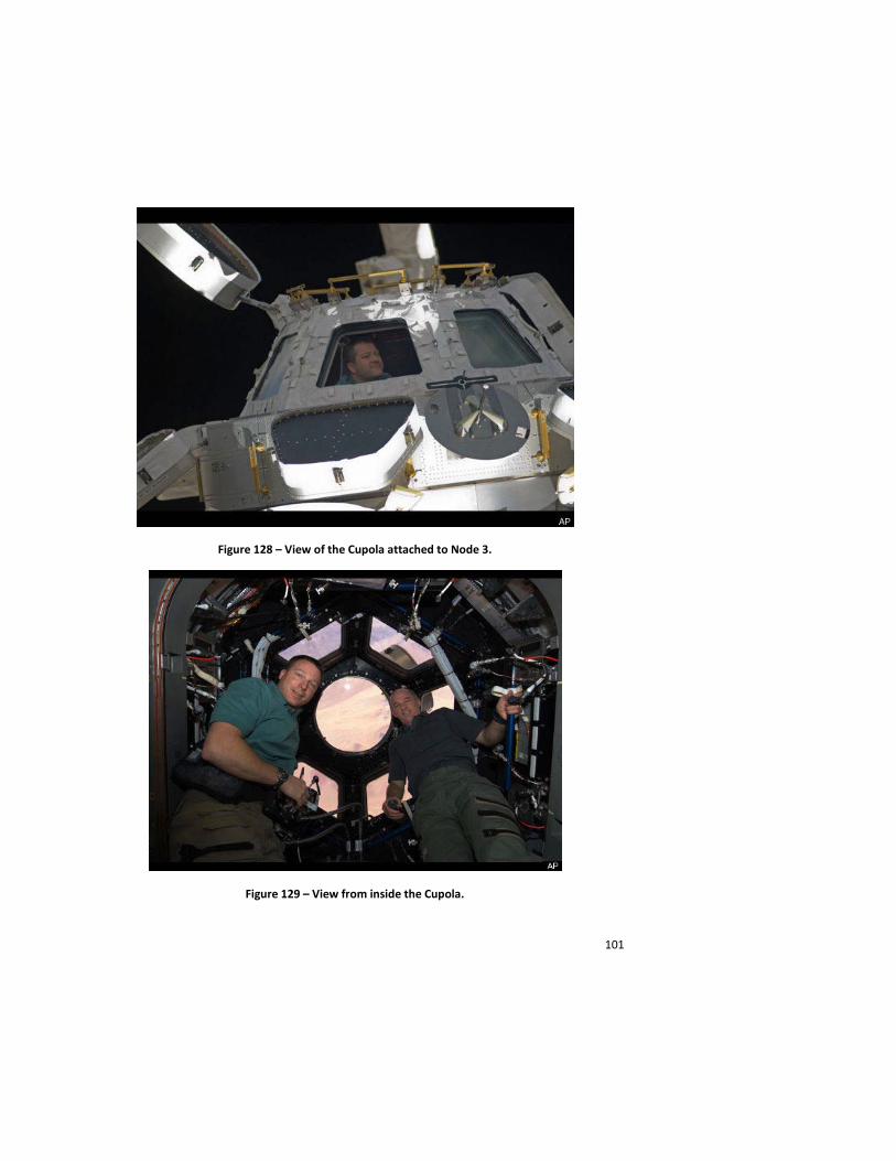
The Node3/Cupola was launched by STS-130 on February 8, 2010. It was successfully ingressed on that mission and has provided views for some of the most spectacular imagery of both the Earth and the ISS from inside the ISS (Figure 128 and Figure 129).
97
Figure 126 – Summary of the Cupola STA window pressure test campaign.
98
Figure 126 (continued) – Summary of the Cupola STA window pressure test campaign.
99
Figure 126 (concluded) – Summary of the Cupola STA window pressure test campaign.
100
Figure 127 – Cupola flight article element level leak test.
101
Figure 128 – View of the Cupola attached to Node 3.
Figure 129 – View from inside the Cupola.
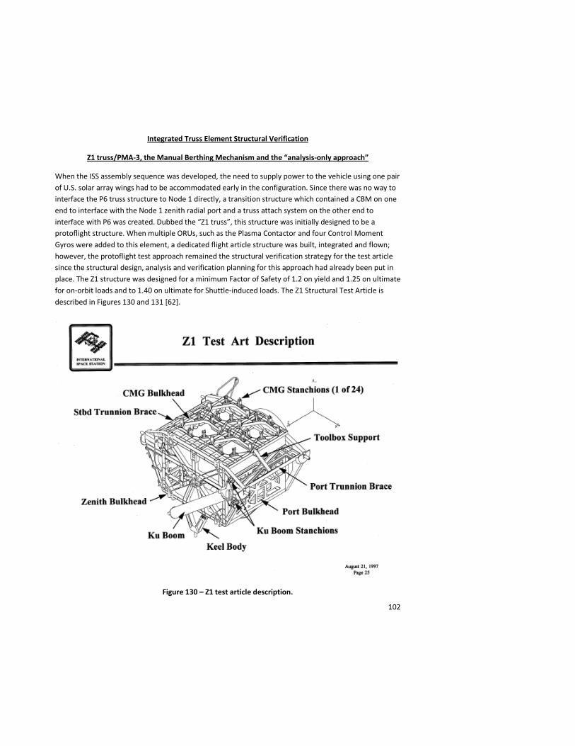
102
Integrated Truss Element Structural Verification
Z1 truss/PMA-3, the Manual Berthing Mechanism and the “analysis-only approach”
When the ISS assembly sequence was developed, the need to supply power to the vehicle using one pair of U.S. solar array wings had to be accommodated early in the configuration. Since there was no way to interface the P6 truss structure to Node 1 directly, a transition structure which contained a CBM on one end to interface with the Node 1 zenith radial port and a truss attach system on the other end to interface with P6 was created. Dubbed the “Z1 truss”, this structure was initially designed to be a protoflight structure. When multiple ORUs, such as the Plasma Contactor and four Control Moment Gyros were added to this element, a dedicated flight article structure was built, integrated and flown; however, the protoflight test approach remained the structural verification strategy for the test article since the structural design, analysis and verification planning for this approach had already been put in place. The Z1 structure was designed for a minimum Factor of Safety of 1.2 on yield and 1.25 on ultimate for on-orbit loads and to 1.40 on ultimate for Shuttle-induced loads. The Z1 Structural Test Article is described in Figures 130 and 131 [62].
Figure 130 – Z1 test article description.

103
Figure 131 – Z1 Test Article Description.
The Z1 truss was static tested to 1.2 x limit load at The Boeing Company (then Rocketdyne) - Canoga Park facility (Figure 132) [63]. The longeron trunnions were exercised with a trunnion planarity loads case (Figure 133) [64]. The interface on Z1 to the P6 truss was tested to 1.2 x limit load (Figure 134) [65]. The CBM, having been qualified as part of the Node 1 structural test series, was not static tested, but a pressure test of a dome that was integrated with the CBM in order to recover the CBM Control Panel Assemblies from the Node 1 zenith port was tested to 22.8 psid after the element was delivered to KSC (Figure 135) [66]. The Z1 structural test article was thoroughly instrumented with deflection transducers and strain gages (Figure 136) [67] in order to correlate the finite element model (Figure 137) [68]. Despite the best efforts of the team, due to the stiffness of the Z1 truss, the 1.2 x limit load requirement was not achieved on the Z1 truss keel trunnion during the static test. The test only achieved 1.08 times limit load. The Z1 keel trunnion was analyzed and found to have very high margin of safety, so an exception (SSCN 1995) to this requirement was submitted and approved by both the Shuttle and ISS Programs.
A modal survey and sine sweep test of this structure was used to verify the dynamic model provided to the Shuttle Program for Verification Loads Analysis (Figure 138) [69]. The Z1 acoustic test to the 141 dB OASPL environment for 180 seconds was performed successfully in the Boeing reverberant acoustic chamber in Kent, Washington (Figure 139) [70]. The ORUs were represented primarily by MTAM (mass-thermal-acoustic-mock-ups), but some qualification hardware was included (Figure 140) [71].
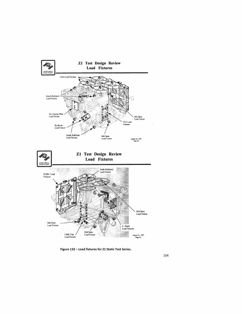
104
Figure 132 – Load fixtures for Z1 Static Test Series.
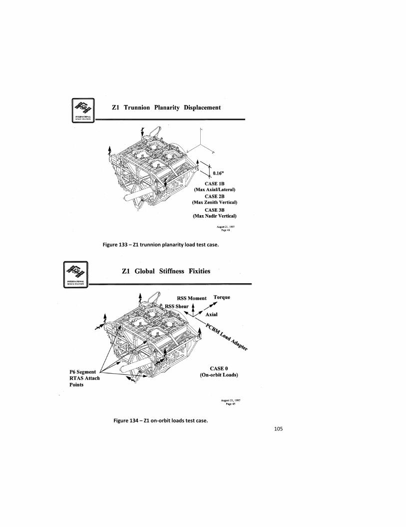
105
Figure 133 – Z1 trunnion planarity load test case.
Figure 134 – Z1 on-orbit loads test case.

106
Figure 135 – Views of Z1 test article showing PCBM interface and Pressure Dome.
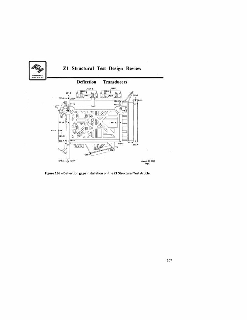
107
Figure 136 – Deflection gage installation on the Z1 Structural Test Article.
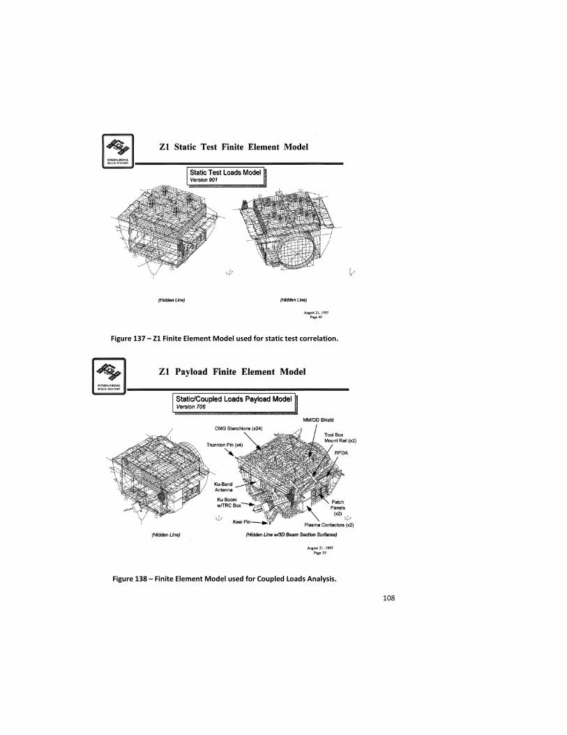
108
Figure 137 – Z1 Finite Element Model used for static test correlation.
Figure 138 – Finite Element Model used for Coupled Loads Analysis.
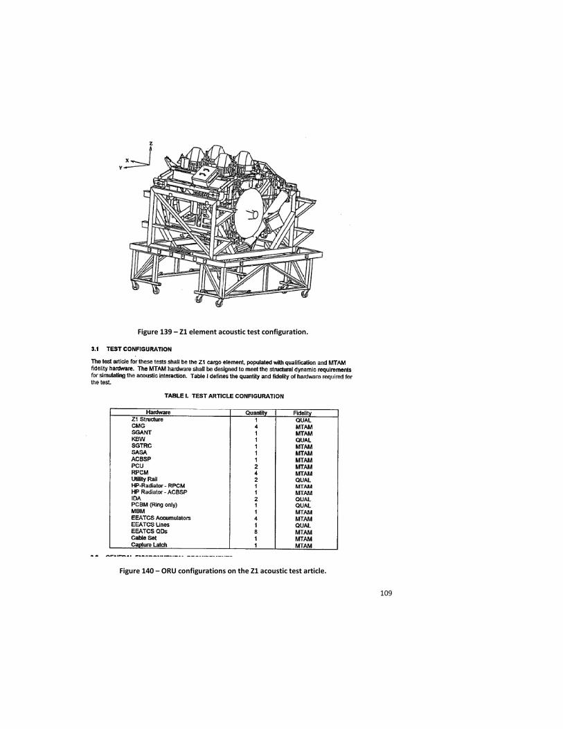
109
Figure 139 – Z1 element acoustic test configuration.
Figure 140 – ORU configurations on the Z1 acoustic test article.

110
On the STS-92 mission in October 2000, the PMA-3 was delivered to orbit with the Z1 truss. A Manual Berthing Mechanism (MBM), mounted to a Spacelab Pallet in the Orbiter cargo bay, interfaced with the CBM on PMA-3 and was used to provide an attachment system that was strong enough to support the PMA-3 for launch, but yet was able to be released by the EVA crewmembers once on-orbit. Two MBM units were built, one to be flown in the Orbiter and one that was permanently attached to the Z1 truss. While a thermal-vacuum, acoustic and modal test was performed on one MBM assembly, no static testing was performed on this unit, nor on the PMA to which it was attached.
It is illustrative at this time to discuss the “no-test” or “analysis-only” approach to structural verification. It is pragmatically impossible to test every load-bearing component on a complex structure. Also, due to schedule, budget or technical constraints sometimes large elements are not amenable to full scale static testing. The structural integrity of these elements must still be validated by some means.
In such cases where structural analysis is the primary method of structural verification for ISS primary and major secondary structures, significant scrutiny was given to the load derivation process, the complexity of the structural load paths, the materials used in construction of the hardware, the analytical methods employed and the factors of safety imposed on design. Most untested ISS primary and secondary structure was designed to a minimum factor of safety of 2.0 on ultimate loads with only a few exceptions.
All untested structure was reviewed by both the ISS and Shuttle programs as well as by the responsible NASA structural engineers and safety communities. It should be emphasized that merely using a factor of safety of 2.0 does not imply that structural verification by analysis only is an acceptable option. As was written into CxP 70135, Structural Design and Verification Requirements for the Constellation Program and included in NSTS 14046, Payload Verification Requirements for the Space Shuttle (Section 5.1.1.3.1), there are no “analysis-only” factors of safety. The verification of a structure must be considered on a case-by-case basis, and the appropriate verification methods must be considered based on both the requirements and the design of that specific piece of hardware.
P6/S6 truss, Photovoltaic Radiator (PVR)
The P6 truss, launched on STS-97, November 30, 2000, was one of the heaviest and largest structures attached to the ISS. It spanned almost the entire usable length of the Orbiter payload bay and contained four longeron and two keel trunnions, which constrained it in one more Degree of Freedom (DOF) than a typical Shuttle payload. It contained a truss section, two photovoltaic thermal control system radiators used as the early active thermal control system for the ISS, an Integrated Electronics Assembly (IEA) section with a third radiator dedicated to the photovoltaic power system, multiple components of the electrical power system including batteries, battery charge/discharge units and voltage regulators, two solar array wings in their stowed configurations and a beta gimbal assembly for each solar array wing to articulate each array mast individually to track the solar beta angle. The P6 truss segment consisted of axial force members constructed out of aluminum and arranged in a box pattern. The IEA was constructed from mechanically fastened machined aluminum bulkheads.
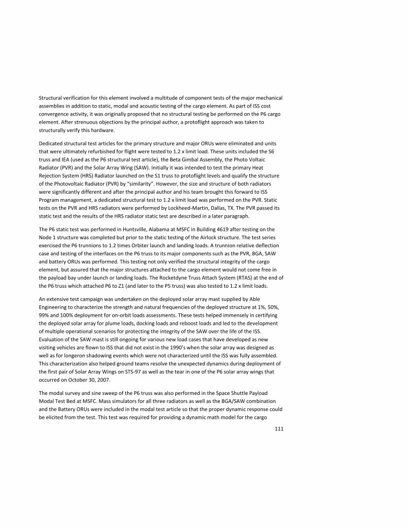
111
Structural verification for this element involved a multitude of component tests of the major mechanical assemblies in addition to static, modal and acoustic testing of the cargo element. As part of ISS cost convergence activity, it was originally proposed that no structural testing be performed on the P6 cargo element. After strenuous objections by the principal author, a protoflight approach was taken to structurally verify this hardware.
Dedicated structural test articles for the primary structure and major ORUs were eliminated and units that were ultimately refurbished for flight were tested to 1.2 x limit load. These units included the S6 truss and IEA (used as the P6 structural test article), the Beta Gimbal Assembly, the Photo Voltaic Radiator (PVR) and the Solar Array Wing (SAW). Initially it was intended to test the primary Heat Rejection System (HRS) Radiator launched on the S1 truss to protoflight levels and qualify the structure of the Photovoltaic Radiator (PVR) by “similarity”. However, the size and structure of both radiators were significantly different and after the principal author and his team brought this forward to ISS Program management, a dedicated structural test to 1.2 x limit load was performed on the PVR. Static tests on the PVR and HRS radiators were performed by Lockheed-Martin, Dallas, TX. The PVR passed its static test and the results of the HRS radiator static test are described in a later paragraph.
The P6 static test was performed in Huntsville, Alabama at MSFC in Building 4619 after testing on the Node 1 structure was completed but prior to the static testing of the Airlock structure. The test series exercised the P6 trunnions to 1.2 times Orbiter launch and landing loads. A trunnion relative deflection case and testing of the interfaces on the P6 truss to its major components such as the PVR, BGA, SAW and battery ORUs was performed. This testing not only verified the structural integrity of the cargo element, but assured that the major structures attached to the cargo element would not come free in the payload bay under launch or landing loads. The Rocketdyne Truss Attach System (RTAS) at the end of the P6 truss which attached P6 to Z1 (and later to the P5 truss) was also tested to 1.2 x limit loads.
An extensive test campaign was undertaken on the deployed solar array mast supplied by Able Engineering to characterize the strength and natural frequencies of the deployed structure at 1%, 50%, 99% and 100% deployment for on-orbit loads assessments. These tests helped immensely in certifying the deployed solar array for plume loads, docking loads and reboost loads and led to the development of multiple operational scenarios for protecting the integrity of the SAW over the life of the ISS. Evaluation of the SAW mast is still ongoing for various new load cases that have developed as new visiting vehicles are flown to ISS that did not exist in the 1990’s when the solar array was designed as well as for longeron shadowing events which were not characterized until the ISS was fully assembled. This characterization also helped ground teams resolve the unexpected dynamics during deployment of the first pair of Solar Array Wings on STS-97 as well as the tear in one of the P6 solar array wings that occurred on October 30, 2007.
The modal survey and sine sweep of the P6 truss was also performed in the Space Shuttle Payload Modal Test Bed at MSFC. Mass simulators for all three radiators as well as the BGA/SAW combination and the Battery ORUs were included in the modal test article so that the proper dynamic response could be elicited from the test. This test was required for providing a dynamic math model for the cargo
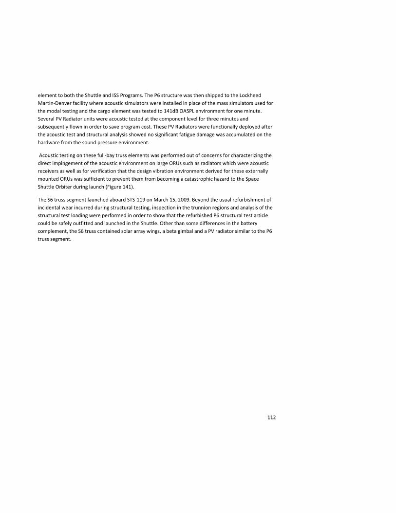
112
element to both the Shuttle and ISS Programs. The P6 structure was then shipped to the Lockheed Martin-Denver facility where acoustic simulators were installed in place of the mass simulators used for the modal testing and the cargo element was tested to 141dB OASPL environment for one minute. Several PV Radiator units were acoustic tested at the component level for three minutes and subsequently flown in order to save program cost. These PV Radiators were functionally deployed after the acoustic test and structural analysis showed no significant fatigue damage was accumulated on the hardware from the sound pressure environment.
Acoustic testing on these full-bay truss elements was performed out of concerns for characterizing the direct impingement of the acoustic environment on large ORUs such as radiators which were acoustic receivers as well as for verification that the design vibration environment derived for these externally mounted ORUs was sufficient to prevent them from becoming a catastrophic hazard to the Space Shuttle Orbiter during launch (Figure 141).
The S6 truss segment launched aboard STS-119 on March 15, 2009. Beyond the usual refurbishment of incidental wear incurred during structural testing, inspection in the trunnion regions and analysis of the structural test loading were performed in order to show that the refurbished P6 structural test article could be safely outfitted and launched in the Shuttle. Other than some differences in the battery complement, the S6 truss contained solar array wings, a beta gimbal and a PV radiator similar to the P6 truss segment.
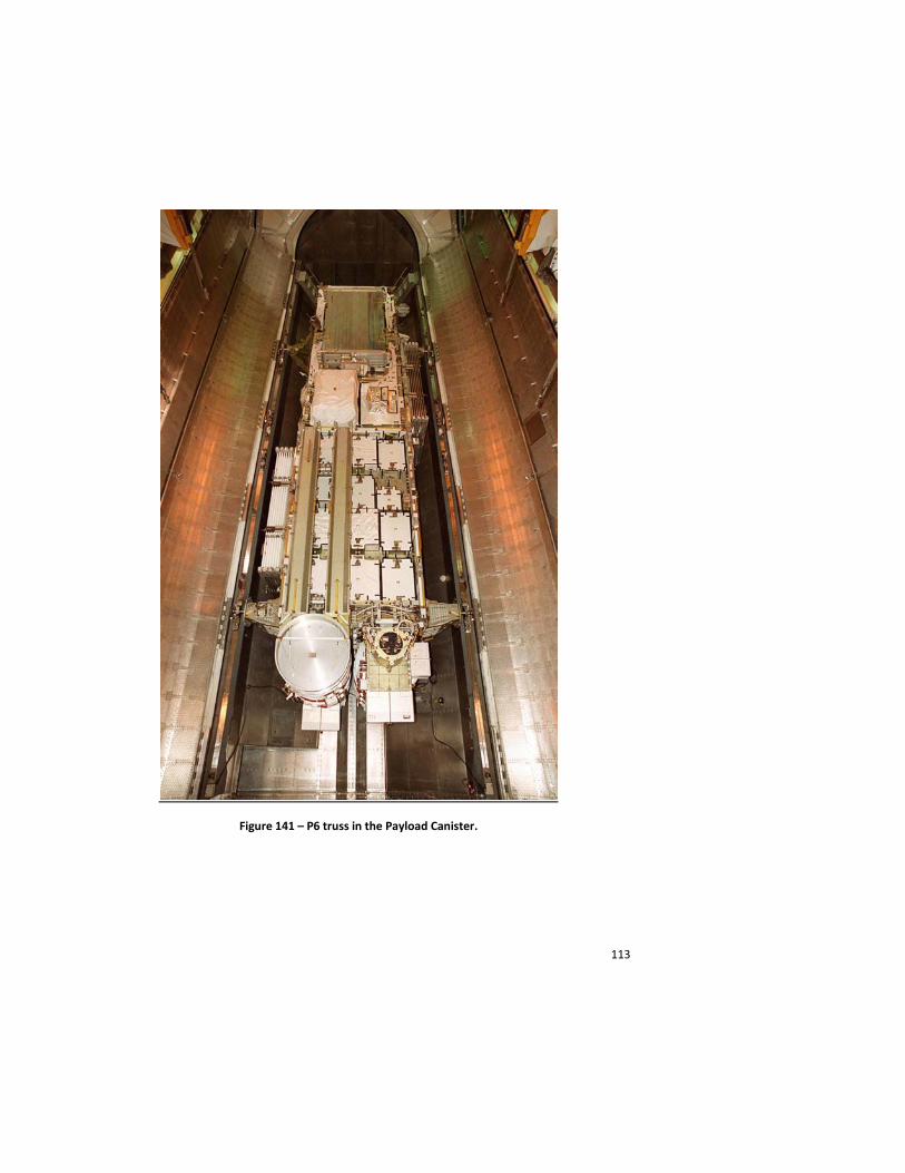
113
Figure 141 – P6 truss in the Payload Canister.
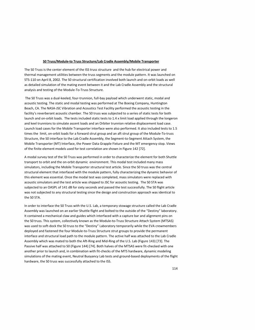
114
S0 Truss/Module-to Truss Structure/Lab Cradle Assembly/Mobile Transporter
The S0 Truss is the center element of the ISS truss structure and the hub for electrical power and thermal management utilities between the truss segments and the module pattern. It was launched on STS-110 on April 8, 2002. The S0 structural certification involved both launch and on-orbit loads as well as detailed simulation of the mating event between it and the Lab Cradle Assembly and the structural analysis and testing of the Module-To-Truss Structure.
The S0 Truss was a dual-keeled, four-trunnion, full-bay payload which underwent static, modal and acoustic testing. The static and modal testing was performed at The Boeing Company, Huntington Beach, CA. The NASA-JSC Vibration and Acoustics Test Facility performed the acoustic testing in the facility’s reverberant acoustic chamber. The S0 truss was subjected to a series of static tests for both launch and on-orbit loads. The tests included static tests to 1.4 x limit load applied through the longeron and keel trunnions to simulate ascent loads and an Orbiter trunnion relative displacement load case. Launch load cases for the Mobile Transporter interface were also performed. It also included tests to 1.5 times the limit, on-orbit loads for a forward strut group and an aft strut group of the Module-To-truss Structure, the S0 interface to the Lab Cradle Assembly, the Segment-to-Segment Attach System, the Mobile Transporter (MT) Interface, the Power Data Grapple Fixture and the MT emergency stop. Views of the finite element models used for test correlation are shown in Figure 142 [72].
A modal survey test of the S0 Truss was performed in order to characterize the element for both Shuttle transport to orbit and the on-orbit dynamic environment. This modal test included many mass simulators, including the Mobile Transporter structural test article. Since the S0 truss was the central structural element that interfaced with the module pattern, fully characterizing the dynamic behavior of this element was essential. Once the modal test was completed, mass simulators were replaced with acoustic simulators and the test article was shipped to JSC for acoustic testing. The S0 STA was subjected to an OASPL of 141 dB for sixty seconds and passed the test successfully. The S0 flight article was not subjected to any structural testing since the design and construction approach was identical to the S0 STA.
In order to interface the S0 Truss with the U.S. Lab, a temporary stowage structure called the Lab Cradle Assembly was launched on an earlier Shuttle flight and bolted to the outside of the “Destiny” laboratory. It contained a mechanical claw and guides which interfaced with a capture bar and alignment pins on the S0 truss. This system, collectively known as the Module-to-Truss Structure Attach System (MTSAS) was used to soft-dock the S0 truss to the “Destiny” Laboratory temporarily while the EVA crewmembers deployed and fastened the four Module-to-Truss Structure strut groups to provide the permanent interface and structural load path to the module pattern. The active half was attached to the Lab Cradle Assembly which was mated to both the Aft-Ring and Mid-Ring of the U.S. Lab (Figure 143) [73]. The Passive half was attached to S0 (Figure 144) [74]. Both halves of the MTSAS were fit-checked with one another prior to launch and, in combination with fit-checks of the MTS hardware, dynamic modeling simulations of the mating event, Neutral Buoyancy Lab tests and ground-based deployments of the flight hardware, the S0 truss was successfully attached to the ISS.
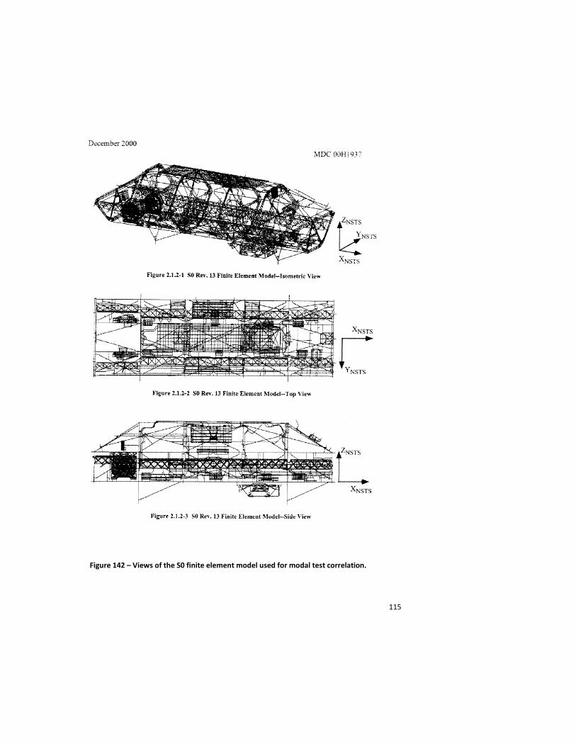
115
Figure 142 – Views of the S0 finite element model used for modal test correlation.
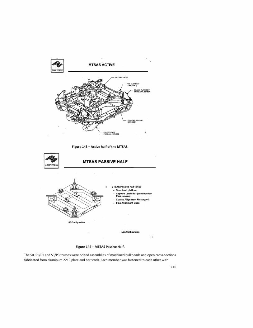
116
Figure 143 – Active half of the MTSAS.
Figure 144 – MTSAS Passive Half.
The S0, S1/P1 and S3/P3 trusses were bolted assemblies of machined bulkheads and open cross-sections fabricated from aluminum 2219 plate and bar stock. Each member was fastened to each other with

117
multiple bolts. The Module-To-Truss Structure (MTS) struts interfaced with the U.S. Lab through a set of EVA installed fasteners integrated to an attach plate on the end of each strut group. These connections, once assembled by EVA had to withstand on-orbit dynamic loads as well as pressure and thermal cycling for the life of the ISS (Figure 145) [75]. The S0 truss provides a good example of some of the issues with designing and analyzing the bolted joints on the ISS. Ensuring the structural integrity of the bolted joints across the ISS was a continuous challenge throughout the development phase of the ISS Program.
Figure 145 – Module-to-Truss Structure Forward Struts, Lab Cradle Assembly and MTSAS.
NSTS 08307, “Criteria for Pre-loaded Bolts” was the governing document for analysis of bolted connections on the USOS ISS elements. This document presents various methods for preloaded joint analysis. Uncertainty factors for applied preload, preload losses due to thermal effects, typical nut factors and the recommendation to perform application specific torque tension testing are included in this document. Because of the myriad of applications, there were some concerns that the methods in this document result in overly conservative joint designs. Also, some of the recommendations for preload loss and nut factors may not be applicable to the unique structural designs used in all spacecraft applications. The bolted joint analysis criteria was recently revisited by industry experts and a multi-center team of NASA structural engineers to incorporate ISS lessons learned and develop new, less conservative preloaded joint analysis criteria. This will be published as NASA-STD-5020, Requirements for Threaded Fastening Systems in Spaceflight Hardware.

118
For the MTS strut interface, the attach bolts between the MTS Structure and the “Destiny” Lab Module had to be sized to be installed with the maximum torque available to the EVA crewmembers using the Pistol Grip Tool (PGT) and yet still be strong enough to maintain a preloaded joint over the life of the ISS.
Figure 146 – Module-To-Truss structure showing aft and forward strut interface plates.
The massive EVA assembly task of the ISS (exceeding 150 spacewalks as of 10/28/10) was made possible due to the teamwork and extensive upfront engineering to make each on-orbit assembly task friendly to the EVA crew. The design challenges for the structural engineers to develop many EVA bolted interfaces were complex. Structural analysis taking into account preload uncertainties, tolerances, thermal effects and PGT performance were performed for each EVA joint provided ground engineers the data to advise the EVA crewmembers to apply higher installation torques, if required, when a bolt could not be seated (Figure 146)[76]. In addition to bolted joint analysis, worksite analysis and strategic placement of handholds and foot restraints, every removable and replaceable ORU had tolerance analysis performed for maximum/minimum material conditions and on-orbit thermal differential to assure that they could successfully be removed and replaced on-orbit. Multiple spacewalks have been performed removing and replacing ORUs of various sizes and no issues due to installation/removal tolerance mismatch have occurred.

119
The S0 truss contained all of the utility trays and umbilicals that distributed power and cooling from the primary power and active thermal control systems. A detailed tolerance analysis of the fit of all of the Module-to-Truss structure strut groups along with each deployable umbilical tray that was launched attached to S0 was performed to assure that the dimensional stack-up of the different on-orbit mated interfaces did not exceed the adjustability and compliance that was designed into the various struts, fluid lines, electrical lines and mechanical interfaces between the trays and the module pattern. In addition, “on-orbit constraints testing” was performed for all electrical and fluid connector and umbilical tray connections to be made by EVA crewmembers. These tests involved exercising the individual umbilical trays and connections on the ground prior to launch using simulators to verify to the greatest extent possible that the EVA mating of these trays and umbilicals would take place successfully. It was during an on-orbit constraints test of one of the S0 to Lab umbilical trays that interference was noted in the hinge joint of the tray that would have prevented successful deployment on-orbit. This problem was corrected and the tray was successfully deployed during the STS-110 mission.
The S0 truss was launched to orbit on April 8, 2002 on the STS-110 mission. It was installed on the “Destiny” laboratory on April 11, 2002 during the first of four spacewalks performed on that mission to perform the myriad of structural and utility line mating operations to attach the truss segment to the station. The successful installation of the S0 onto the ISS heralded the beginning of the construction of the backbone of the ISS.
S1/P1 Truss, Thermal Radiator Rotary Joint (TRRJ) and Central Thermal Control System Heat Rejection System (HRS) Radiator
The S1 Truss (and its companion P1 Truss) contains the thermal control system for the ISS. Each truss carries three HRS radiators in their stowed configuration, the Thermal Radiator Rotary Joint (TRRJ) (provided by Lockheed Martin – Sunnyvale, CA), an Ammonia tank, a Nitrogen tank and a Pump Module (one of which was changed out by EVA in August 2010) (Figure 148)[78].
A static, modal and acoustic test campaign was undertaken on this element, along with a dedicated static test on the deployed HRS radiator. The truss element static test was performed at The Boeing Company – Huntington Beach, CA. The static test campaign for launch loads was reduced to a single load case of 1.4 times limit loads due to schedule and budget constraints. The Segment-to-Segment Attach System (SSAS) and the PDGF interfaces were tested to 1.5 x on-orbit limit loads. An excellent discussion of the static test is provided in the paper “International Space Station Alpha (ISSA) Starboard Integrated Truss Segment 1 (S1) Static Loads Structural Qualification Test – A Recipe for Success” by S. Zimmerman and G. Barnett [79]. The modal test campaign included mass simulators for the HRS radiators and TRRJ (Figure 149) [80], the ammonia tank assembly (Figure 150) [81], the nitrogen tank assembly (Figure 151) [82] and the pump module. A moment of drama occurred after the modal test when the S1 STA was being lifted from its test stand for shipment to JSC for the acoustic test. The aft trunnions had not been unbolted so the article was lifted by its forward trunnions only during the move operation. The test article was inspected and structural analysis performed for this inadvertent load case. No damage or overstress condition was indicated.
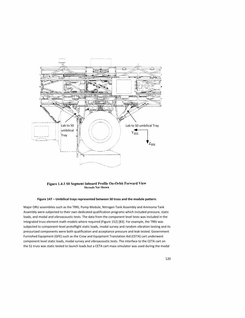
120
Figure 147 – Umbilical trays represented between S0 truss and the module pattern.
Major ORU assemblies such as the TRRJ, Pump Module, Nitrogen Tank Assembly and Ammonia Tank Assembly were subjected to their own dedicated qualification programs which included pressure, static loads, and modal and vibroacoustic tests. The data from the component level tests was included in the integrated truss element math models where required (Figure 152) [83]. For example, the TRRJ was subjected to component-level protoflight static loads, modal survey and random vibration testing and its pressurized components were both qualification and acceptance pressure and leak tested. Government Furnished Equipment (GFE) such as the Crew and Equipment Translation Aid (CETA) cart underwent component level static loads, modal survey and vibroacoustic tests. The interface to the CETA cart on the S1 truss was static tested to launch loads but a CETA cart mass simulator was used during the modal
Lab to S0 umbilical Tray Lab to S0 umbilical Tray
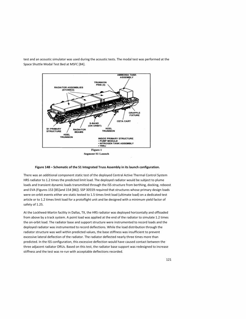
121
test and an acoustic simulator was used during the acoustic tests. The modal test was performed at the Space Shuttle Modal Test Bed at MSFC [84].
Figure 148 – Schematic of the S1 Integrated Truss Assembly in its launch configuration.
There was an additional component static test of the deployed Central Active Thermal Control System HRS radiator to 1.2 times the predicted limit load. The deployed radiator would be subject to plume loads and transient dynamic loads transmitted through the ISS structure from berthing, docking, reboost and EVA (Figures 153 [85]and 154 [86]). SSP 30559 required that structures whose primary design loads were on-orbit events either are static tested to 1.5 times limit load (ultimate load) on a dedicated test article or to 1.2 times limit load for a protoflight unit and be designed with a minimum yield factor of safety of 1.25.
At the Lockheed-Martin facility in Dallas, TX, the HRS radiator was deployed horizontally and offloaded from above by a track system. A point load was applied at the end of the radiator to simulate 1.2 times the on-orbit load. The radiator base and support structure were instrumented to record loads and the deployed radiator was instrumented to record deflections. While the load distribution through the radiator structure was well within predicted values, the base stiffness was insufficient to prevent excessive lateral deflection of the radiator. The radiator deflected nearly three times more than predicted. In the ISS configuration, this excessive deflection would have caused contact between the three adjacent radiator ORUs. Based on this test, the radiator base support was redesigned to increase stiffness and the test was re-run with acceptable deflections recorded.
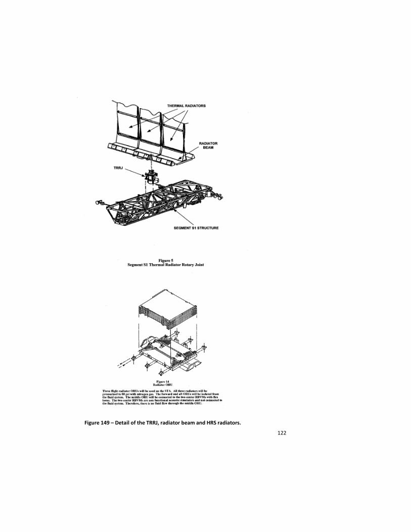
122
Figure 149 – Detail of the TRRJ, radiator beam and HRS radiators.
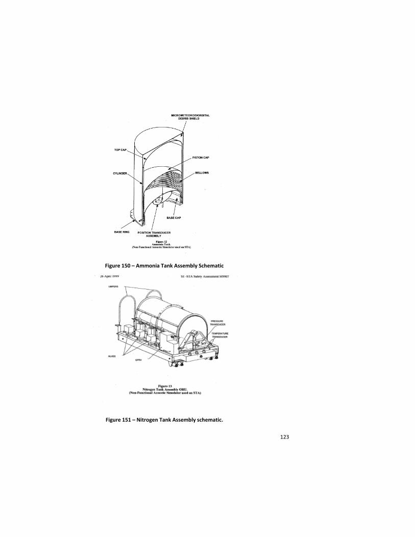
123
Figure 150 – Ammonia Tank Assembly Schematic
Figure 151 – Nitrogen Tank Assembly schematic.
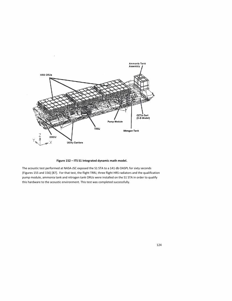
124
Figure 152 – ITS S1 Integrated dynamic math model.
The acoustic test performed at NASA-JSC exposed the S1 STA to a 141 db OASPL for sixty seconds (Figures 155 and 156) [87]. For that test, the flight TRRJ, three flight HRS radiators and the qualification pump module, ammonia tank and nitrogen tank ORUs were installed on the S1 STA in order to qualify this hardware to the acoustic environment. This test was completed successfully.
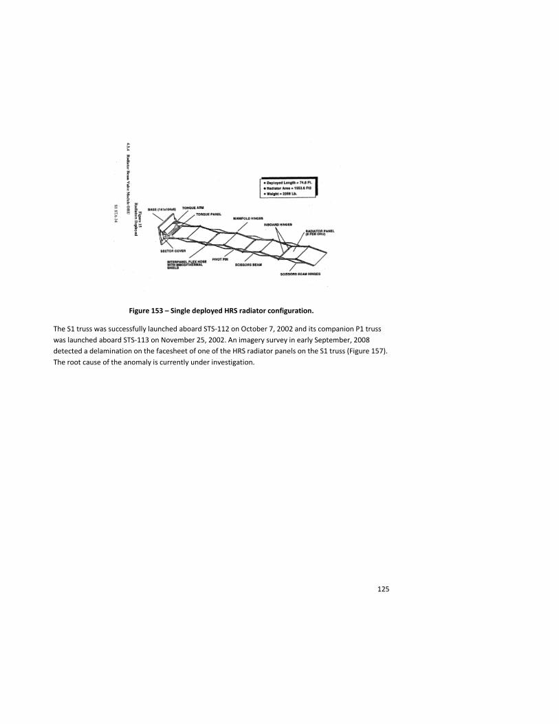
125
Figure 153 – Single deployed HRS radiator configuration.
The S1 truss was successfully launched aboard STS-112 on October 7, 2002 and its companion P1 truss was launched aboard STS-113 on November 25, 2002. An imagery survey in early September, 2008 detected a delamination on the facesheet of one of the HRS radiator panels on the S1 truss (Figure 157). The root cause of the anomaly is currently under investigation.
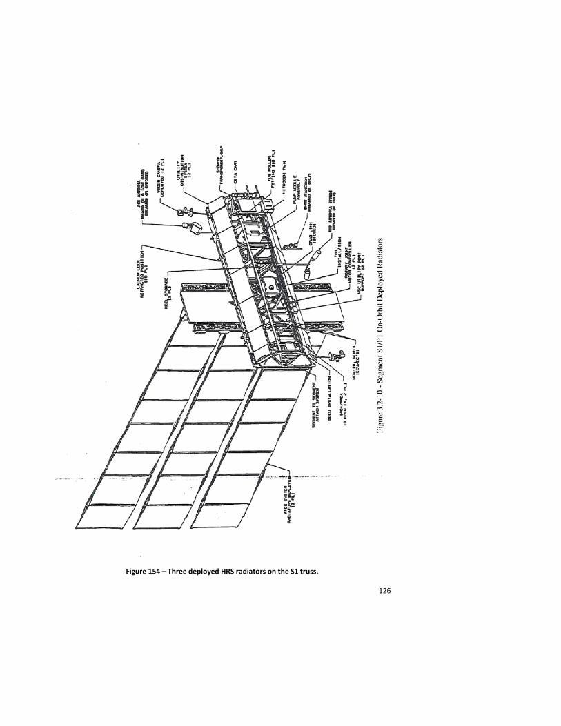
126
Figure 154 – Three deployed HRS radiators on the S1 truss.
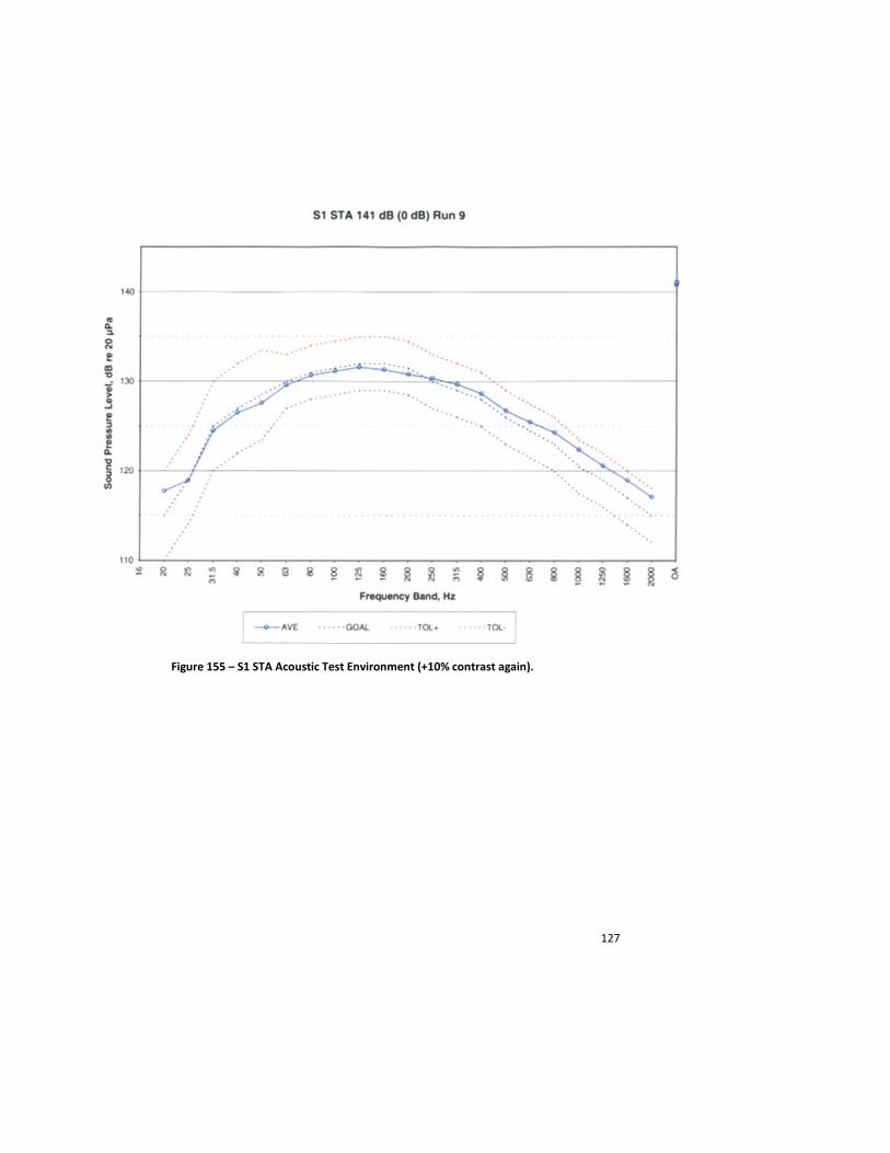
127
Figure 155 – S1 STA Acoustic Test Environment (+10% contrast again).
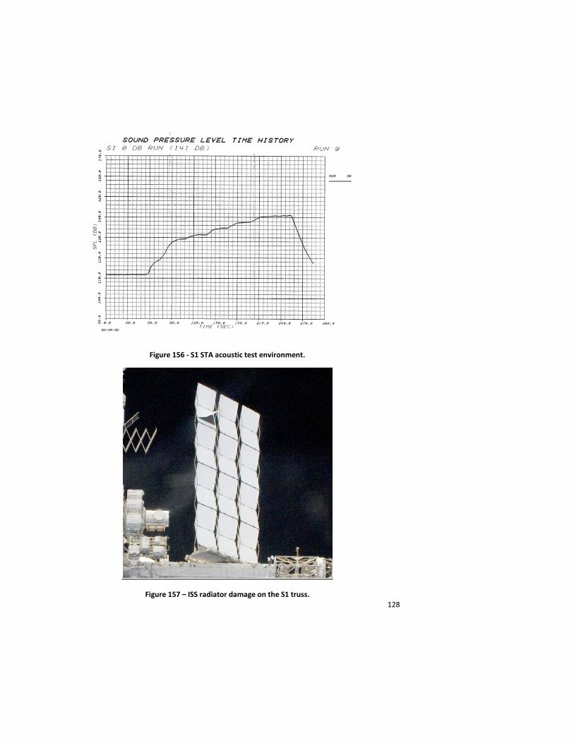
128
Figure 156 - S1 STA acoustic test environment.
Figure 157 – ISS radiator damage on the S1 truss.
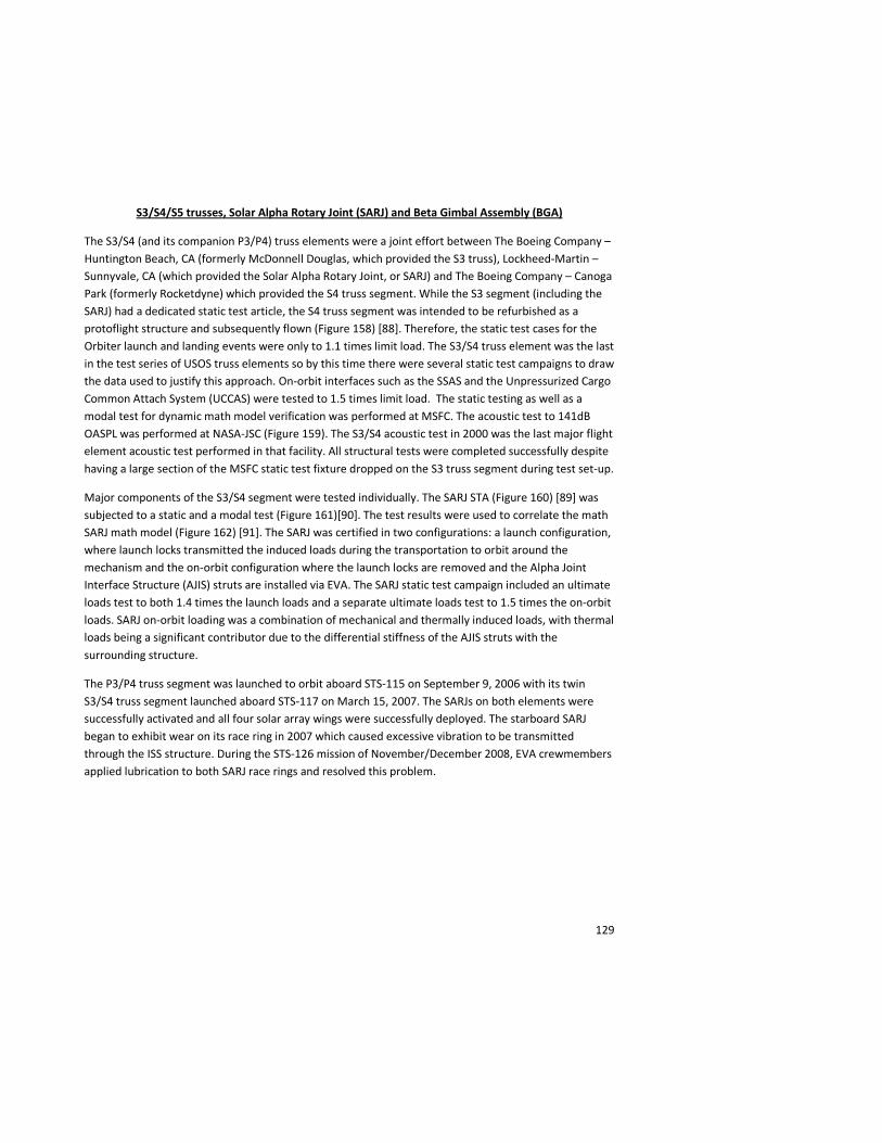
129
S3/S4/S5 trusses, Solar Alpha Rotary Joint (SARJ) and Beta Gimbal Assembly (BGA)
The S3/S4 (and its companion P3/P4) truss elements were a joint effort between The Boeing Company – Huntington Beach, CA (formerly McDonnell Douglas, which provided the S3 truss), Lockheed-Martin – Sunnyvale, CA (which provided the Solar Alpha Rotary Joint, or SARJ) and The Boeing Company – Canoga Park (formerly Rocketdyne) which provided the S4 truss segment. While the S3 segment (including the SARJ) had a dedicated static test article, the S4 truss segment was intended to be refurbished as a protoflight structure and subsequently flown (Figure 158) [88]. Therefore, the static test cases for the Orbiter launch and landing events were only to 1.1 times limit load. The S3/S4 truss element was the last in the test series of USOS truss elements so by this time there were several static test campaigns to draw the data used to justify this approach. On-orbit interfaces such as the SSAS and the Unpressurized Cargo Common Attach System (UCCAS) were tested to 1.5 times limit load. The static testing as well as a modal test for dynamic math model verification was performed at MSFC. The acoustic test to 141dB OASPL was performed at NASA-JSC (Figure 159). The S3/S4 acoustic test in 2000 was the last major flight element acoustic test performed in that facility. All structural tests were completed successfully despite having a large section of the MSFC static test fixture dropped on the S3 truss segment during test set-up.
Major components of the S3/S4 segment were tested individually. The SARJ STA (Figure 160) [89] was subjected to a static and a modal test (Figure 161)[90]. The test results were used to correlate the math SARJ math model (Figure 162) [91]. The SARJ was certified in two configurations: a launch configuration, where launch locks transmitted the induced loads during the transportation to orbit around the mechanism and the on-orbit configuration where the launch locks are removed and the Alpha Joint Interface Structure (AJIS) struts are installed via EVA. The SARJ static test campaign included an ultimate loads test to both 1.4 times the launch loads and a separate ultimate loads test to 1.5 times the on-orbit loads. SARJ on-orbit loading was a combination of mechanical and thermally induced loads, with thermal loads being a significant contributor due to the differential stiffness of the AJIS struts with the surrounding structure.
The P3/P4 truss segment was launched to orbit aboard STS-115 on September 9, 2006 with its twin S3/S4 truss segment launched aboard STS-117 on March 15, 2007. The SARJs on both elements were successfully activated and all four solar array wings were successfully deployed. The starboard SARJ began to exhibit wear on its race ring in 2007 which caused excessive vibration to be transmitted through the ISS structure. During the STS-126 mission of November/December 2008, EVA crewmembers applied lubrication to both SARJ race rings and resolved this problem.
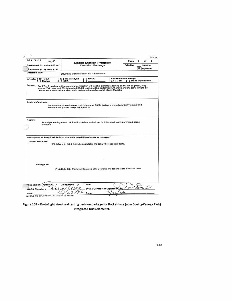
130
Figure 158 – Protoflight structural testing decision package for Rocketdyne (now Boeing-Canoga Park) integrated truss elements.
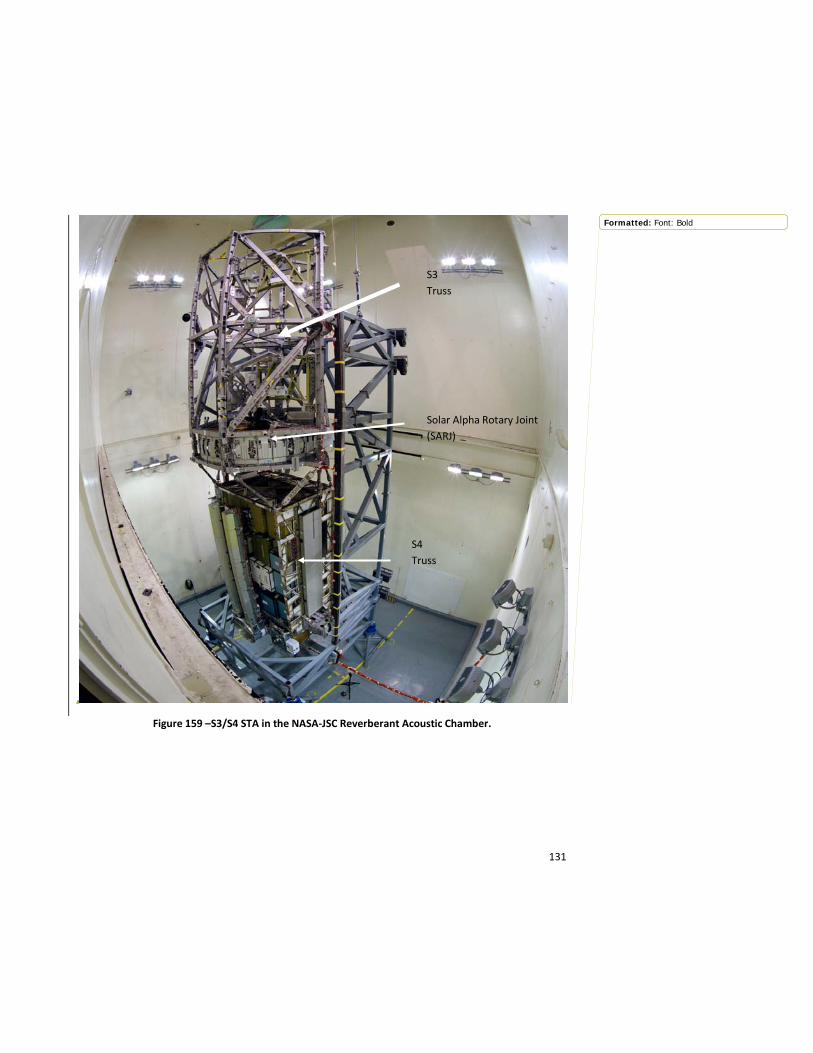
131
Figure 159 –S3/S4 STA in the NASA-JSC Reverberant Acoustic Chamber.
S3 Truss
Solar Alpha Rotary Joint (SARJ)
S4 Truss
Formatted: Font: Bold
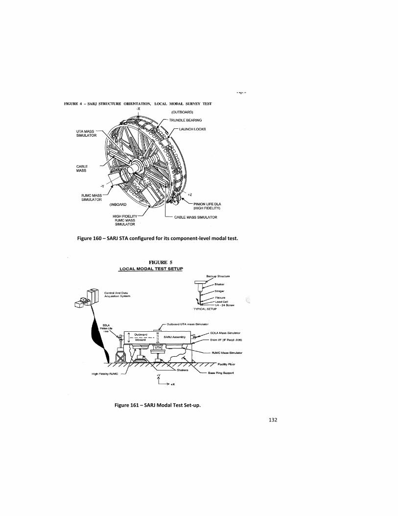
132
Figure 160 – SARJ STA configured for its component-level modal test.
Figure 161 – SARJ Modal Test Set-up.

133
Figure 162 – SARJ Math Model used for Modal test Correlation.
The P5 truss (and its companion truss segment S5) was not static tested. Only a modal test was performed in the Space Shuttle Payload Modal Test Bed at MSFC to verify the dynamic math model for Orbiter and ISS integration. An interesting issue arose during the P5 modal test. Since the struts which make up P5 were axial force members, the “play” inherent in each strut installation caused the first natural frequency to be slightly different for the same input force. This non-linearity was thoroughly scrutinized by the dynamicists responsible for the testing and a verified math model was provided to both the ISS and Shuttle Programs with the help of sensitivity studies to define the effects of the non-linearity. P5 was launched aboard STS-116 on December 9, 2006 and S5 was launched aboard STS-118 on August 8, 2007.
The Beta Gimbal Assembly was attached to the IEA through an EVA-deployable four-bar linkage. A protoflight static test of the four bar linkage to 1.2 times the predicted on-orbit loads was performed. This test was particularly useful when during deployment of one of the BGAs, only three of the four bars fully locked in place. Engineers on the ground were able to use the results of the static test to demonstrate structural integrity with only three of four linkages seated.
ISS Composite Rack
Most of the internal equipment and payload hardware for the USOS modules was transported to orbit in bookcase-shaped, graphite-epoxy composite racks. Manufactured by The Boeing Company in Huntsville, Alabama, these racks were designed to be installed into a pressurized element both on the ground and on-orbit. Common interfaces between the rack and the interior pressurized module structure are
134
present within Node 1, Node 2 and Node 3, the U.S. Lab, the Airlock and the MPLM. The H-II Transfer Vehicle (HTV) was also designed to accommodate these composite racks. The majority of large experiments and critical ISS systems equipment is brought to ISS fully integrated in these racks. Each rack is designed to be transported to and from orbit with a requirement for 15 launches and landings through its lifetime. Launch and return of some of these racks is via the MPLM.
With the variety of possible payload and rack equipment configurations, the structural verification test campaign had to provide data that would be generic enough to be applicable for verifying a myriad of rack applications, and yet be specific to physically-realizable equipment configurations. For example, there were four-post and six-post International Standard Payload Racks, four-post and six-post equipment racks, two types of stowage racks which had interfaces with an Aisle Stowage Container, and drawer and equipment configurations tailored for each rack application.
After a great deal of discussion between the rack developers at Boeing-Huntsville and the ISS and Shuttle Program structures teams, a strategy was agreed upon to provide the required static strength and dynamic math model verification data for the various racks. The Dash-6 Rack modal survey in both fixed-base and free-free configuration included four shelves loaded with various distributed masses amongst the shelves. The Dash-4 Rack modal survey was tested in both fixed base and free-free configurations with an integrated mass of either 400 kilograms or 700 kilograms concentrated at various locations within the rack. Static testing of the Dash-6 Rack was performed to envelope the various interface loads for rack transport to and from orbit. The Dash-11 Static Loads test included load cases for internal equipment as well as the Aisle Stowage Container. During this static loads test series, the rack post failed prior to 140% of limit load. The Dash-11 rack was determined to be sufficiently similar to the Dash-4 rack so that no modal test of the Dash-11 rack was required [92].
The rack posts were composite I-beam sections with the shelves attaching to one of the I-beam flanges. The inertia loads of equipment attached to the shelves applied a torsion load to the flange/web interface that exceeded its structural capability. A test program was undertaken to characterize the strength of this interface and assure that the weight of the equipment on the rack shelves would be less than this value for all rack applications. After the maximum shelf load was recalculated, the static test on the rack post due to shelf loading was performed successfully to 140% of limit load. In addition, the buckling calculation for the large curved panel which composed the back of the rack showed that this panel could buckle under launch and landing loads. A hat-section stiffener was incorporated into the aft panel design, reducing the unsupported length of the aft panel and alleviating this concern. The racks have been flown to and from orbit without any issues since 1998 (Figure 163).

135
Figure 163 –Rack being maneuvered into its position inside the Lab Module.
Other rack hardware has since been developed to provide transportation of payload hardware to and from orbit, such as the Resupply Stowage Platform (RSP). This hardware is essentially a plate which ties into the rack attach points within the MPLM. Stowage bags filled with soft goods and other equipment are strapped to the front and back of the RSPs. The structural verification of this configuration included a modal survey and static test as well as detailed characterization of the strap configurations to assure that sufficient preload was applied to prevent adjacent bags from contacting during launch. Such contact could cause unacceptable load sharing between the platforms. During static testing, excessive deflections of the bags were noted which led to the development of fences around each of the bags which prohibited load-sharing between adjacent bags during launch or landing.
136
Structural Life Certification Approach
FLAGRO vs. Fatigue Testing
The primary tool used to verify the structural life of metallic structures on ISS was FLAGRO (now NASGRO), an analysis tool developed by NASA for fatigue crack growth and fracture analysis. SSP 30558 defined the activities required by the ISS hardware developers to minimize the risk of structural failure due to crack propagation. The on-orbit life of the ISS primary structure was specified as 15 years from delivery of the hardware element to orbit. Transient loading events and their accompanying load spectra were derived and fracture and fatigue analysis per SSP 30558 was performed on all ISS elements to certify the hardware for this 15-year on-orbit service life. All loading events from the time of manufacture, including any structural testing, ground transportation and delivery to orbit were encompassed by the load spectra used in the structural life analysis. A scatter factor of four based on the metallic material fatigue data available was used on the load spectra.
FLAGRO was used by NASA, JAXA and ESA to perform structural life verification. The Russian contributors to the ISS employed fatigue testing to certify the structural life of their elements using a scatter factor of 8 for their fatigue testing on the load-bearing interfaces of both the FGB and the Service Module. With the proposal to extend the life of the ISS to at least 2020, a structural life extension effort is underway comprised of additional NASGRO analysis by NASA, ESA and JAXA, and additional fatigue testing by the Russians. On January 14, 2009, anomalous thruster firings during a Service Module reboost imparted significant oscillations into the ISS structure. While no immediate structural integrity concerns were identified based on analysis of this event, the life extension efforts for the ISS will use all loading events measured on the ISS to date using the on-orbit instrumentation as well as prediction for future on-orbit loads from visiting vehicle, maneuvers and EVA.
The NASGRO material database is the analysis program’s greatest strength as well as its biggest liability. Since all possible material product forms, heat treatments and crack growth orientations are not available in the database, users must make assumptions as to what data is applicable to their particular piece of flight hardware. Even when the proper similitude between the database and the flight hardware exists, any production lot and/or vendor source variations within the properties are not directly accounted for in the database. Since fracture is rarely a design driver for ISS applications because of stiffness-driven designs, the low duty cycle usage environment, and positive margins of safety for high static strength factors of safety, analysis-only service life predictions using NASGRO can be performed.
Most of the ISS structure is essentially uninspectable once it is assembled. The truss elements are wrapped in Multi-Layer Insulation Blankets, the pressurized elements are covered with MM/OD protection and the interior of the ISS is filled with racks and stowed equipment. The truss structure is highly redundant and designed primary for launch loads and stiffness so the unlikely event of on-orbit damage or failure of a truss structural member is not a significant threat to ISS structural integrity. External surveys of the ISS using video cameras and during EVA has shown evidence of MM/OD impacts
137
on handrails and other structure and while this damage can pose a sharp edge hazard to EVA crewmembers, there has been no threat to the structural integrity of ISS from MM/OD impacts thus far. The MM/OD shielding on the majority of the ISS pressurized elements is removable and most of the internal pressure walls of the modules can be accessed by folding the racks down or removing equipment. The Module-to-Truss Structure struts can support on-orbit loads with any one strut removed.
The pressure vessels were designed to an ultimate factor of safety of 2.0 to lower the working stresses and are leak before burst designs. The Composite Overwrapped Pressure Vessel stress rupture life for ISS pressure vessels became a concern when more data became available on graphite-epoxy and Kevlar-epoxy overwrapped pressure vessels which called the initial service life calculations into question. Since NASGRO can only analyze metallic materials and glass, stress-rupture life assessments for COPVs must be based on test data. Therefore, more testing will be done in the coming months to supplement the original 1994-1995 stress rupture life data upon which the service life predictions for the ISS pressure vessels are based. This is part of the ISS life extension effort since the ISS COPVs were only certified to a 15-year, on-orbit service life.
Periodic updates to the NASGRO software are made as more crack growth data is developed. Materials used in the Russian Segment of the ISS were tested and analysis was performed by both U.S. and Russian structural engineers in order for both sets of specialists to become familiar and comfortable with the different approaches to structural life verification. With the challenge of extending the life of ISS to 2020 and beyond, all of the latest material data as well as loads predictions from the ISS integrated math-model and on-orbit data from accelerometers and strain gages installed on the ISS vehicle itself will be used.
Lessons Learned and Suggestions for Future Spacecraft
The construction and assembly of the ISS has proven that the world can come together and accomplish any task if the commitment of the groups involved is strong enough. This has to be the first lesson of the ISS: cooperation among international partners is not only possible, but is indeed, practical and necessary.
Another lesson is that complex aerospace structures can be developed and certified on a limited budget, if the proper attention is paid throughout the structural analysis and design process. While it could be argued that the protoflight structural test approach was a significant risk to the ISS Program, the diligence of the structural designers, analysts and test engineers involved in the development of the hardware managed this risk successfully. No major structural failures occurred during the test program and the hardware was certified with sufficient margin to appropriately conservative loads to make structural life extension of the on-orbit ISS possible.
Extensive pre-test analysis was performed prior to each structural test and after some initial difficulties with the Node 1 pressure test campaign, a Test Design Review (TDR)/ Test Readiness Review (TRR) board process was instituted so that all stakeholders could review the objectives, test sequence and

138
configuration of the structural test article and raise any issues early in the structural test development process. This approach was fundamental to the success of the ISS and should be employed in all spacecraft structural test efforts.
The amount of effort required to certify the windows on the ISS was not understood by the hardware developers at the outset, but once the NASA-JSC and KSC glass experts were involved an excellent cooperative relationship emerged between NASA, the U.S. contractors and the International Partners. These relationships should be established early so that the particulars of window structural verification are understood before the structural verification plan for the entire spacecraft is developed.
On-orbit pre-integrated structural health monitoring instrumentation should be the standard practice for characterizing the on-orbit loads environment for spacecraft. The principal author and his structures team fought to keep the accelerometers and strain gages which comprised the Structural Dynamic Measurement System (SDMS) pre-integrated on the S0, S1/P1 and S3/P3 truss elements against enormous Program pressure to delete them as a cost savings. The data from this instrumentation was invaluable in diagnosing and solving the SARJ race-ring damage anomaly which threatened the power-generation capability of the ISS. Instrumentation packages have been flown to ISS and installed both internally (Internal Wireless Instrumentation System – IWIS) and externally (External Wireless Instrumentation System – EWIS) by the on-orbit crew, but this has been a significant cost in both dollars and EVA and IVA crew time (Figure 164). Instrumentation that is already present when the spacecraft is launched is the most cost-effective and technically prudent strategy to gather on-orbit structural response data. However, rapid change in the data acquisition system technology over the long life of an on-orbit structure could lead to obsolescence concerns with the hardware and the data acquisition and transfer modes.
Figure 164 – On-orbit structural health monitoring instrumentation locations on ISS as of May, 2011.
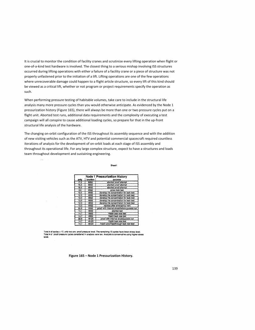
139
It is crucial to monitor the condition of facility cranes and scrutinize every lifting operation when flight or one-of-a-kind test hardware is involved. The closest thing to a serious mishap involving ISS structures occurred during lifting operations with either a failure of a facility crane or a piece of structure was not properly unfastened prior to the initiation of a lift. Lifting operations are one of the few operations where unrecoverable damage could happen to a flight article structure, so every lift of this kind should be viewed as a critical lift, whether or not program or project requirements specify the operation as such.
When performing pressure testing of habitable volumes, take care to include in the structural life analysis many more pressure cycles than you would otherwise anticipate. As evidenced by the Node 1 pressurization history (Figure 165), there will always be more than one or two pressure cycles put on a flight unit. Aborted test runs, additional data requirements and the complexity of executing a test campaign will all conspire to cause additional loading cycles, so prepare for that in the up-front structural life analysis of the hardware.
The changing on-orbit configuration of the ISS throughout its assembly sequence and with the addition of new visiting vehicles such as the ATV, HTV and potential commercial spacecraft required countless iterations of analysis for the development of on-orbit loads at each stage of ISS assembly and throughout its operational life. For any large complex structure, expect to have a structures and loads team throughout development and sustaining engineering.
Figure 165 – Node 1 Pressurization History.
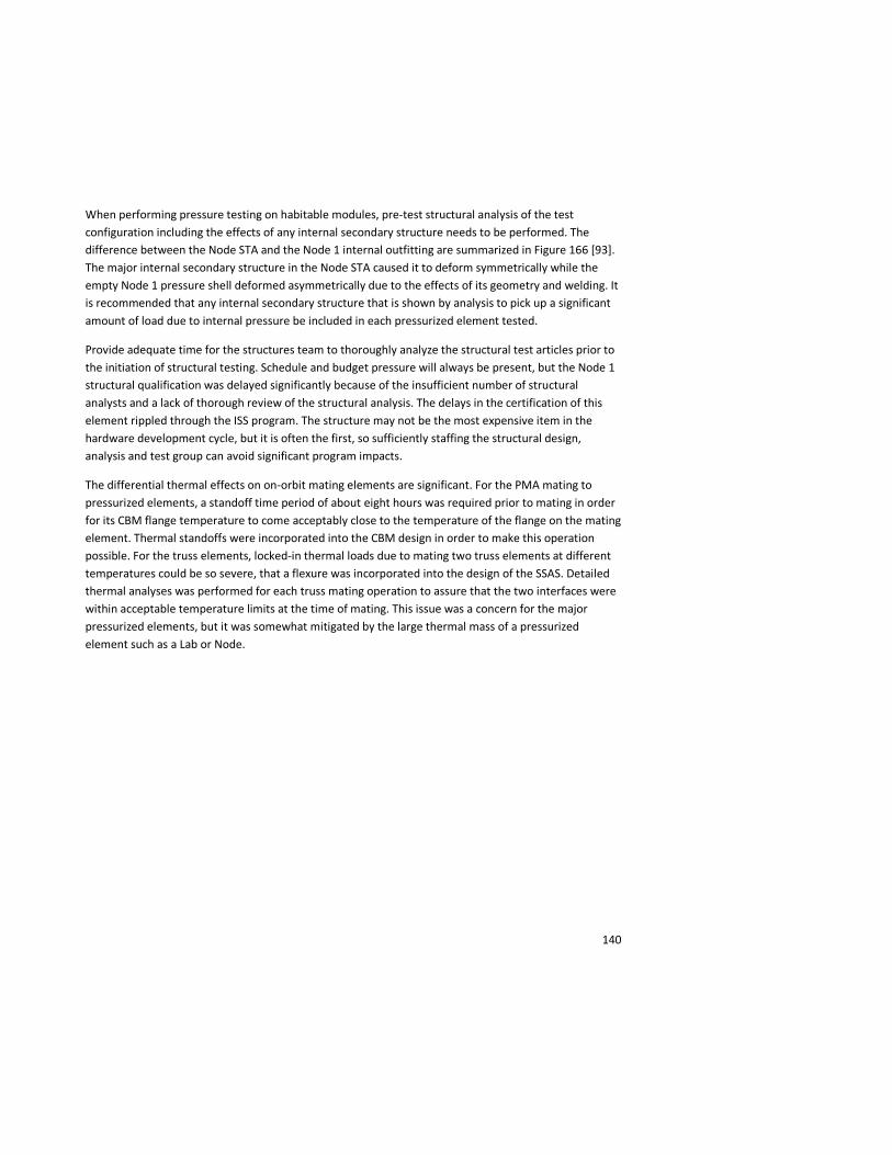
140
When performing pressure testing on habitable modules, pre-test structural analysis of the test configuration including the effects of any internal secondary structure needs to be performed. The difference between the Node STA and the Node 1 internal outfitting are summarized in Figure 166 [93]. The major internal secondary structure in the Node STA caused it to deform symmetrically while the empty Node 1 pressure shell deformed asymmetrically due to the effects of its geometry and welding. It is recommended that any internal secondary structure that is shown by analysis to pick up a significant amount of load due to internal pressure be included in each pressurized element tested.
Provide adequate time for the structures team to thoroughly analyze the structural test articles prior to the initiation of structural testing. Schedule and budget pressure will always be present, but the Node 1 structural qualification was delayed significantly because of the insufficient number of structural analysts and a lack of thorough review of the structural analysis. The delays in the certification of this element rippled through the ISS program. The structure may not be the most expensive item in the hardware development cycle, but it is often the first, so sufficiently staffing the structural design, analysis and test group can avoid significant program impacts.
The differential thermal effects on on-orbit mating elements are significant. For the PMA mating to pressurized elements, a standoff time period of about eight hours was required prior to mating in order for its CBM flange temperature to come acceptably close to the temperature of the flange on the mating element. Thermal standoffs were incorporated into the CBM design in order to make this operation possible. For the truss elements, locked-in thermal loads due to mating two truss elements at different temperatures could be so severe, that a flexure was incorporated into the design of the SSAS. Detailed thermal analyses was performed for each truss mating operation to assure that the two interfaces were within acceptable temperature limits at the time of mating. This issue was a concern for the major pressurized elements, but it was somewhat mitigated by the large thermal mass of a pressurized element such as a Lab or Node.
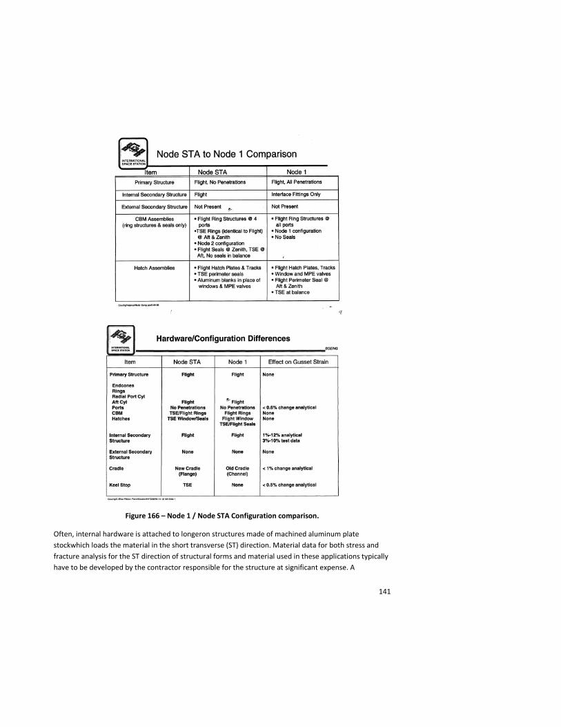
141
Figure 166 – Node 1 / Node STA Configuration comparison.
Often, internal hardware is attached to longeron structures made of machined aluminum plate stockwhich loads the material in the short transverse (ST) direction. Material data for both stress and fracture analysis for the ST direction of structural forms and material used in these applications typically have to be developed by the contractor responsible for the structure at significant expense. A

142
compilation of the ST direction material data that is currently available and an effort to further develop and disseminate a database could be a valuable cost-savings measure for future vehicle programs.
Conclusions
No paper of roughly 21,000 words can do justice to the incredible human effort it took to design, fabricate and structurally test the hardware of the ISS. This paper is a feeble attempt at capturing the experience, knowledge and lessons learned of those involved for posterity. If the current generation can see the ISS in the sky at night and future generations can gain any value by this summary document, limited though it is, on the 26-year effort it took to design and fully-assemble the ISS, this enlightenment is its own reward.
I would like to thank everyone who contributed to this paper as well as the many thousands of others whose work, though uncredited and eventually long-forgotten, made the construction of the ISS possible. Its presence on-orbit is the living tribute to all of you.
Mr. John J. Zipay Deputy Branch Chief, Structures Branch Structural Engineering Division NASA-Lyndon B. Johnson Space Center Houston, Texas May, 2011 Acknowledgements: Dr. Kornel Nagy, Alan Balusek, Karen Bernstein, Robert Davis, Lynda Estes, Vince Fogt, Trevor Kott, Ted Kenny, Guy King, Julie Kramer, Dr. James J. McMahon, Paul Romine, Dr. James P. Smith, Deneen Taylor, Dave Williams / NASA - Lyndon B. Johnson Space Center, Houston TX.; Robert Foster , Ted Bartkowicz, Kauser Imtiaz, Mark Henry, Richard Troutman, Forest Yocum, Phil Shaw, Don Bowen, Alan Dillon, Ray Morrison, Jim Peebles, Jeff Pool, Brian Martiyak, Conrad Ball, John Leuer, Ken Varner - The Boeing Company; Curtis E. Larsen – NASA / NESC; C. Thomas Modlin, Harold Doiron, Orvis E. Pigg – NASA/Lyndon B. Johnson Space Center – retired; Bob Ryan – NASA/George C. Marshall Space Flight Center – retired; Edgar O. Castro, Stan Donahoe, Christopher P. Hansen, Raymond Patin, T. Scott West, Mike Grygier, Daniele Laurini, Alan McDougal, Glenn J. Miller, Ken Wong, William H. Arceneaux NASA-Lyndon B. Johnson Space Center; Robert A. Parrish, Damon Nelson, NASA-John F. Kennedy Space Center; Thomas R. Galloway, NASA - John C. Stennis Space Center; Brian K. Mitchell / NASA – George C. Marshall Spaceflight Center; Gary B. Johnson / SAIC; Dan Collins, Mark Jenks, Dave McCann, Mark Mulqueen, Rich Nordin, Phil Kabre’, Shya-Ling Shein, Paul Smith, Harry Warden, Scott Zimmerman - The Boeing Company; Sam Davis – The Boeing Company – retired.
143
References
1. Kaouk, McNeil, Haley, Grygier, Bartkowicz, Rachal, Peart, ”Shuttle Flight-7A DTO-261: Pre and post Flight Analysis “ and Fitzpatrick, Grygier, Bartkowicz, “ISS Stage 12A Post-Flight Modal Analysis, Model Validation and Correlation”.
2. “Node Proof Pressure Leak Rate Qualification Test”, Presentation. 3. Ibid. 4. Ibid. 5. “Node Blue Ribbon Panel Update”, July 1-2, 1996 and “Node Decision Time Review”, June 15,
1996. 6. Ibid. 7. Ibid. 8. Ibid, Reference 2. 9. Ibid. 10. “Node STA Static Flight Loads Test”, Presentation. 11. Ibid. 12. “Node STA Static Loads Qualification Test Readiness Review”, Presentation, 24 March 1997. 13. “Cancellation of Structural Tests for Node Internal Fittings”, Memo # 2-8H23-SGD-048/97
Revision A, 14 July 1997. 14. Ibid, Reference 12. 15. Unknown. 16. “Node Dynamic Verification Plan – PG3” – 16 January 1996. 17. Ibid. 18. Ibid. 19. “Modal Testing of Seven Shuttle Cargo Elements for Space Station” by K. Kappus, T. Driskill and
R. Parks. 20. “Space Station Decision Package #149: PG-3 Structural test Simplifications”, John J. Zipay
6/23/94. 21. NSTS-21000-IDD-ISS, “International Space Station Interface Definition Document”. 22. “Structural Analysis of Node 1”. 23. Ibid. 24. Ibid, Reference 2. 25. “Flight 2A.1 Node 1 Hatch Inspection and Adjustment” – Node 1 Hatch Anomaly Resolution
Team, Presented to ISS MMT, 31 March 1999. 26. Ibid. 27. Ibid. 28. “Lab/CM STA Pressure and Leak Test Test Design Review”, Presentation, 3 April 1996. 29. Ibid. 30. “Lab/Hab (CM)Modal Survey & Vibroacoustic Test Readiness Review”, Presentation, July 30,
1997. 31. Ibid.
144
32. Yocum, Forrest, “Analysis Overview – Module”, Blue Ribbon Panel Review, August 6, 1996. 33. Ibid. 34. Ibid. 35. Ibid, Reference 27. 36. T683-12900-1,”Common Module Proof Pressure Qual Test Report, Revision New”, 12 June 1997. 37. Ibid. 38. Ibid. 39. Space Station Decision package #37 – “Hab/Lab Module Wall Thickness for MM/OD Protection”,
K. Nagy. 40. “Airlock Structures CDR”, Presentation, 30 April 1996. 41. “Airlock Static Qualification Test Conditions 12, 13 & 2 Influence Coefficients and Endcone
Buckling Test Readiness Review”, Presentation, 17 October, 1997. 42. Ibid. 43. Ibid. 44. Ibid. 45. Ibid. 46. “Airlock ETSD Support Structure Static Test Conditions 3 and 8 (Cond. 2 Rerun) Delta Test
Readiness Review”, Presentation, 6 October 1998. 47. “Airlock Misdrilled Primary Trunnions”, Presentation, 11 October 1996. 48. Ibid. 49. Gamwell, Wayne R., Memo # EH23 (97-35),”BACB30LE4U12 Bolt Testing”, 13 May 1997. 50. Ibid, Reference 39. 51. Morrison, Raymond, ”PMA Pressure Test Overview” portion of the “PMA Production Readiness
Review”, March 14, 1995. 52. Collins, Dan, “Results of Sectioned Coupons: portion of the “PMA Production Readiness Review”,
March 14, 1995. 53. Ibid, Reference 50. 54. Ibid, Reference 50. 55. MDC 95H0336, “Pressurized Mating Adapters Structural Integrity Report: Volumes 1 – 14”, May
1996, Approved by: Kurtkan, F.; Collins D.J.; Crosse D. 56. Ibid. 57. SSMDH-0033, “Flight 3A PMA FSE Static Test Report”, May, 1999. 58. Ibid. 59. Ibid. 60. Ecord, Glenn M.; Patin, Raymond M., “Memo # ES4-05-060, JSC Fracture Control Board Position
for ISS Node 2 Welds”. 61. Estes L.; Zipay J.; Nguyen-Xuan H.; Accardi F.; Rubino S.; Candela F., “Final meeting Minutes:
Cupola Structures and Mechanical Splinter Meeting”, 24 March 1999. 62. “Z1 Cargo Element Static Structural Test Design Review”, 20 August 1997. 63. Ibid. 64. Ibid.
145
65. Ibid. 66. Ibid. 67. Ibid. 68. Ibid. 69. Ibid. 70. EID-05330, “Z1 Acoustic Test Report”, 14 October 1999, prepared by Rahimi, R. 71. Ibid. 72. MDC 00H1937, “S0 Cycle 4.0 NSTS Coupled Loads Analysis”, December, 2000, Approved by
Peebles J. and Nelson J. 73. “Module to Truss Structure Attach System (MTSAS) and MTS Strut Design Overview”,
Presentation. 74. Ibid. 75. CR/SSCN 4566, “S0 MTS Struts Deployment”, Presentation to Vehicle Control Board, 19 March
2001, Johnston S. and Leuer J. 76. Ibid. 77. Ibid, Reference 72. 78. “Integrated Truss Segment S1 Structural Test Article Acoustic Test Safety Assessment Large
Payload Test Facility – JSC”, Brown, Joe B., 26 April 1999. 79. Zimmerman S., Barnett G., “International Space Station Alpha (ISSA) Inboard Truss Cargo
Element Starboard 1 (ITCE-S1) static loads structural qualification test – A recipe for success”, 20th Aerospace Testing Seminar Proceedings, pp. 43-57, 26-28 March 2002.
80. Ibid, Reference 78. 81. Ibid, Reference 78 82. Ibid, Reference 78. 83. MDC 95H0278, “Segment S1/P1 Structural Verification Plan”, Prepared by the S1/P1 Structural
Verification Team, 30 April 1996. 84. Ibid, Reference 19. 85. Ibid, Reference 78. 86. Ibid, Reference 83. 87. JSC 28815, “Acoustic Test of the S1 Structural Test Article Volume III”, Dennis B. Halpin,
September 1999, Vibration and Acoustic Test Facility, Engineering and Development Directorate, Structures and Mechanics Division, Test Branch.
88. Space Station Decision Package # 145, “Structural Certification of PG-2 Hardware, John J. Zipay, 23 June 1994.
89. SARJ STA Modal Test Report, SDS # SS-T-007, Lockheed Martin Corporation Missiles & Space. 90. Ibid. 91. Ibid. 92. D683-60714-1,”Rack Structures Verification Plan, Rev. New”, 11 July 1997. 93. “Node Blue Ribbon Panel Update”, July 1-2, 1996.