Introduction and Overview Presentation by Dale N. Hatfield at the Radio Regulation Summit: Defining...
24
Introduction and Introduction and Overview Overview Presentation by Dale N. Hatfield at the Radio Regulation Summit: Defining Out-of-Band Operating Rules Silicon Flatirons Center for Law, Technology, and Entrepreneurship Boulder September 8 - 9, 2009
Transcript of Introduction and Overview Presentation by Dale N. Hatfield at the Radio Regulation Summit: Defining...
Introduction and OverviewIntroduction and OverviewPresentation by
Dale N. Hatfieldat the
Radio Regulation Summit:
Defining Out-of-Band Operating RulesSilicon Flatirons Center for
Law, Technology, and Entrepreneurship
Boulder
September 8 - 9, 2009
Welcome and Introduction
• Welcome
• Purpose of Summit
• Agenda
• Review of Ground Rules
• Introductions
• Preliminary Remarks

Outline• Welcome and Introduction• Types of Interference• Drawing Geographic Boundaries• Drawing Frequency Boundaries• Out of Band Interference• Drawing Time Boundaries• Introduction of Case Studies
– 800 MHz Rebanding
– AWS-3
– SDARS – WCS
• Other Interference Cases
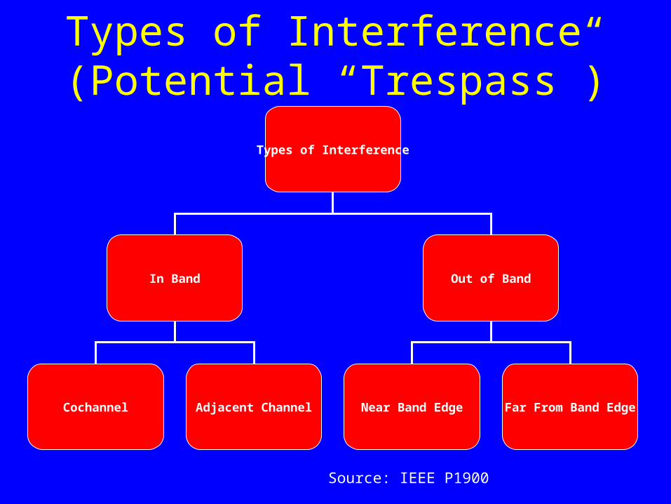
Types of Interference
In Band Out of Band
Cochannel Adjacent Channel Near Band Edge Far From Band Edge
Types of Interference (Potential “Trespass”)
Source: IEEE P1900
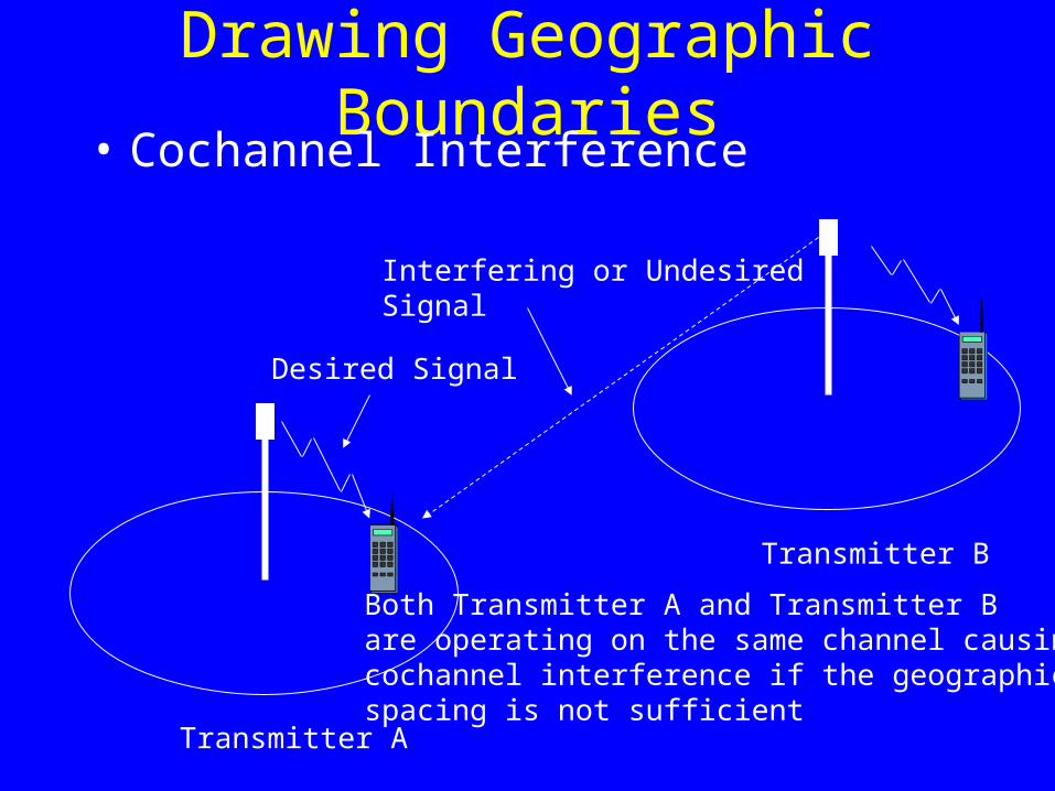
Drawing Geographic Boundaries
Desired Signal
Interfering or UndesiredSignal
Transmitter A
Transmitter B
Both Transmitter A and Transmitter Bare operating on the same channel causingcochannel interference if the geographic spacing is not sufficient
• Cochannel Interference
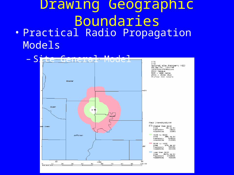
Drawing Geographic Boundaries• Practical Radio Propagation Models
– Site General Model
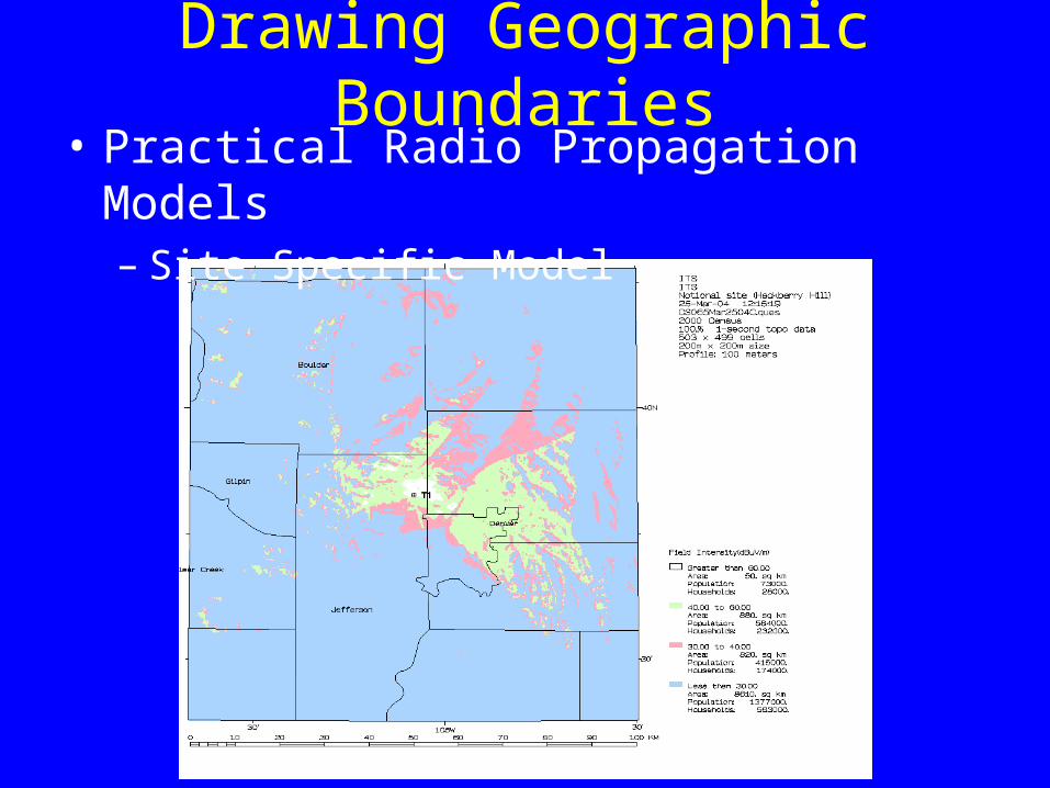
Drawing Geographic Boundaries• Practical Radio Propagation Models
– Site Specific Model
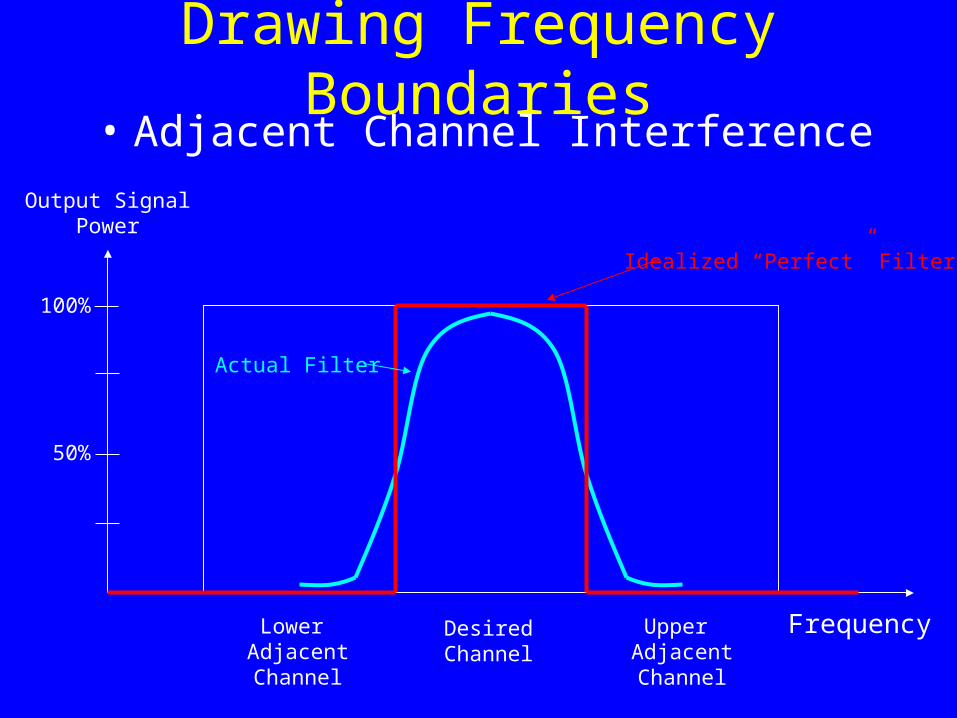
Drawing Frequency Boundaries• Adjacent Channel Interference
Lower AdjacentChannel
Output SignalPower
100%
50%
Upper AdjacentChannel
FrequencyDesiredChannel
Idealized “Perfect” Filter
Actual Filter
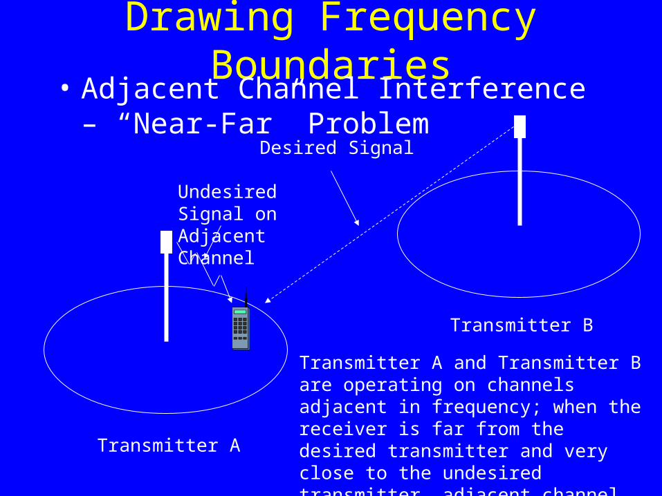
Drawing Frequency Boundaries
Undesired Signal on Adjacent Channel
Desired Signal
Transmitter A
Transmitter B
Transmitter A and Transmitter B are operating on channels adjacent in frequency; when the receiver is far from the desired transmitter and very close to the undesired transmitter, adjacent channel interference is exacerbated
• Adjacent Channel Interference – “Near-Far” Problem
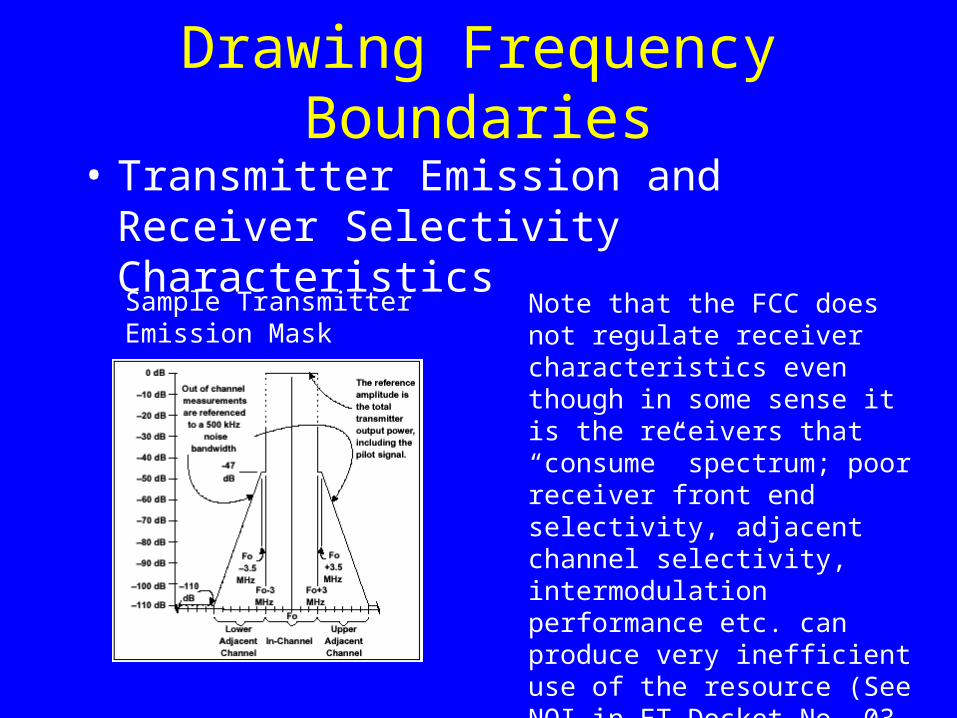
Drawing Frequency Boundaries
• Transmitter Emission and Receiver Selectivity Characteristics
Sample TransmitterEmission Mask
Note that the FCC does not regulate receiver characteristics even though in some sense it is the receivers that “consume” spectrum; poor receiver front end selectivity, adjacent channel selectivity, intermodulation performance etc. can produce very inefficient use of the resource (See NOI in ET Docket No. 03-65, In the Matter of Interference Immunity Performance Specifications for Radio Receivers, Rel. 3/24/03)
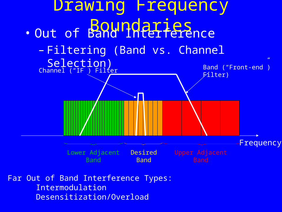
Drawing Frequency Boundaries• Out of Band Interference
– Filtering (Band vs. Channel Selection)
Frequency
Band (“Front-end”)Filter)
Channel (“IF”) Filter
Lower AdjacentBand
DesiredBand
Upper AdjacentBand
Far Out of Band Interference Types:IntermodulationDesensitization/Overload
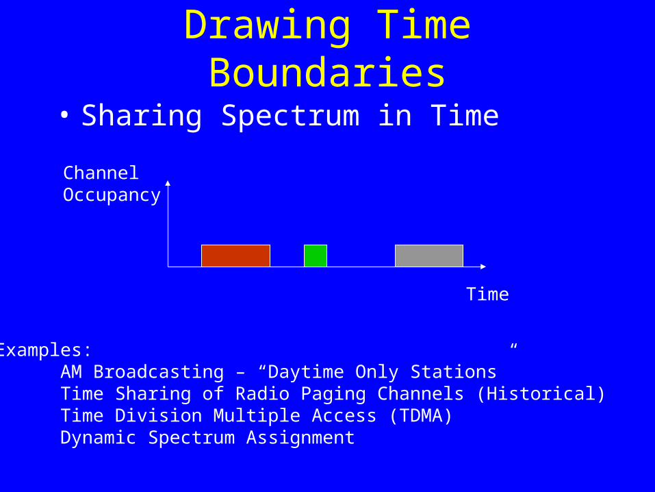
Drawing Time Boundaries
• Sharing Spectrum in Time
Time
ChannelOccupancy
Examples:AM Broadcasting – “Daytime Only Stations”Time Sharing of Radio Paging Channels (Historical)Time Division Multiple Access (TDMA)Dynamic Spectrum Assignment
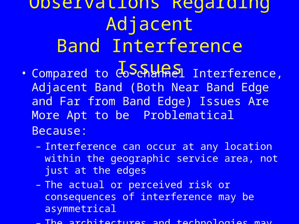
Observations Regarding AdjacentBand Interference Issues
• Compared to Co-channel Interference, Adjacent Band (Both Near Band Edge and Far from Band Edge) Issues Are More Apt to be Problematical Because: – Interference can occur at any location within the geographic
service area, not just at the edges
– The actual or perceived risk or consequences of interference may be asymmetrical
– The architectures and technologies may be vastly different
– The number of players or stakeholders involved may be much larger and involve the general public directly
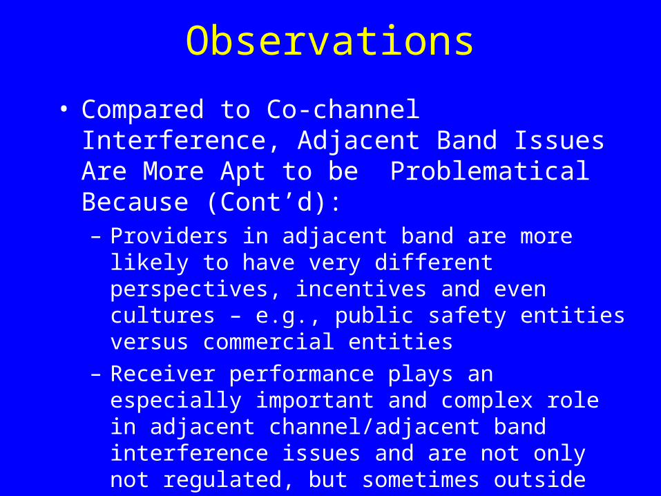
Observations
• Compared to Co-channel Interference, Adjacent Band Issues Are More Apt to be Problematical Because (Cont’d):– Providers in adjacent band are more likely to have very
different perspectives, incentives and even cultures – e.g., public safety entities versus commercial entities
– Receiver performance plays an especially important and complex role in adjacent channel/adjacent band interference issues and are not only not regulated, but sometimes outside the control of the service provider
– Our case studies tend to confirm that hypothesis and that is reason for focusing special attention on the topic in this Summit
Introduction of Case Studies
• 800 MHz Rebanding
• S-DARS – WCS Interference
• AWS-3 Interference

FCC Spectrum Allocationof 800 MHz Band * - Prior to Rebanding
TVBroadcastCh. 60-69
General Category
INCLUDES NEXTEL B/ILT & SMALL
NO. OF PUBLIC SAFETY
Upper 200 SMR(NEXTEL)
806 825816
851 870861 866
809.75
854.75
NPSPAC
821 824
869
- SMR (80 channels) INCLUDES NEXTEL- Business/SMR (50 channels) INCLUDES NEXTEL- Industrial/SMR (50 channels) INCLUDES NEXTEL
- Public Safety (70 channels))*
Up-Link
Down-Link
[7.5 MHz] [12.5 MHz] [10 MHz] [6 MHz]
CELLULAR
Source: APCO/Gurss
800 MHz Rebanding
Interference Concerns:Nextel Adjacent Channel Interference to Public SafetyIntermodulation Interference (Nextel GC, Interleaved, Upper 200, & Cellular A Block)
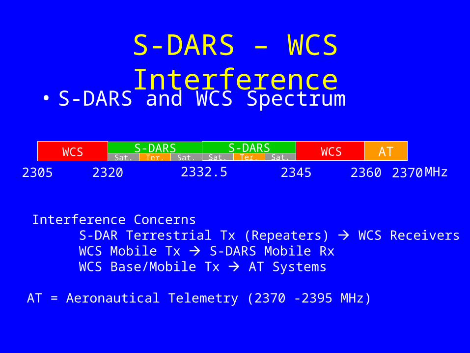
S-DARS – WCS Interference• S-DARS and WCS Spectrum
WCS Sat. Ter. Sat.S-DARS WCSSat.Ter.Sat.
S-DARS
2305 2320 2345 23602332.5 MHz
Interference ConcernsS-DAR Terrestrial Tx (Repeaters) WCS ReceiversWCS Mobile Tx S-DARS Mobile RxWCS Base/Mobile Tx AT Systems
AT
AT = Aeronautical Telemetry (2370 -2395 MHz)
2370
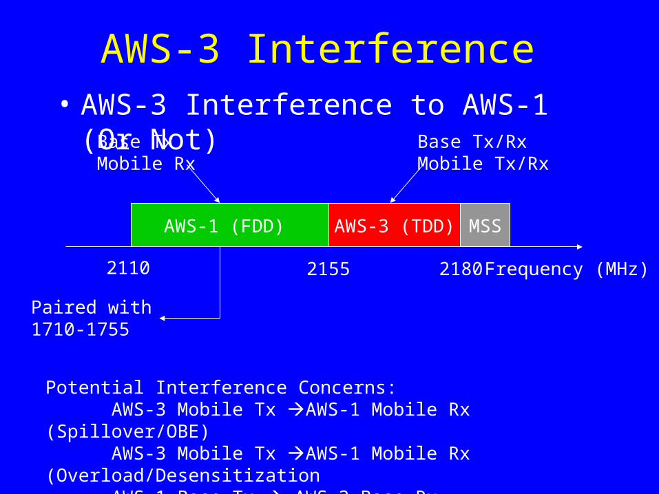
AWS-3 Interference • AWS-3 Interference to AWS-1 (Or Not)
AWS-1 (FDD) AWS-3 (TDD) MSS
Frequency (MHz)2110 2155 2180
Paired with1710-1755
Base TxMobile Rx
Base Tx/RxMobile Tx/Rx
Potential Interference Concerns:AWS-3 Mobile Tx AWS-1 Mobile Rx (Spillover/OBE)AWS-3 Mobile Tx AWS-1 Mobile Rx (Overload/DesensitizationAWS-1 Base Tx AWS-3 Base Rx
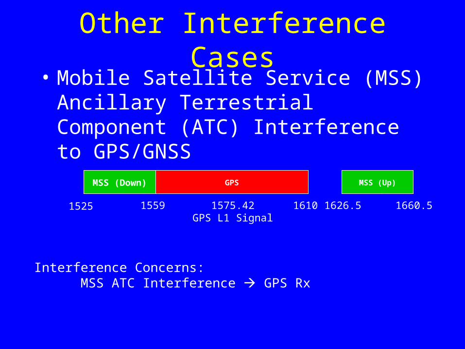
Other Interference Cases• Mobile Satellite Service (MSS) Ancillary
Terrestrial Component (ATC) Interference to GPS/GNSS
MSS (Down) GPS MSS (Up)
1525 1559 1610 1626.5 1660.51575.42GPS L1 Signal
Interference Concerns:MSS ATC Interference GPS Rx
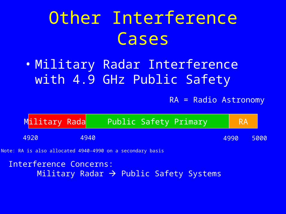
Other Interference Cases
• Military Radar Interference with 4.9 GHz Public Safety
Military Radar Public Safety Primary RA
4920 4940 4990 5000
Interference Concerns:Military Radar Public Safety Systems
RA = Radio Astronomy
Note: RA is also allocated 4940-4990 on a secondary basis

800 MHz Case Study• Potential Discussion Points
– Could Public Safety’s interference rights have been defined adequately to allow cellularization of the SMR spectrum to take place or did the intermixing of the channels and basic incompatibilities between the two uses preclude such a transition as a practical matter?
– If the former, would Coasian bargaining been successful between Nextel and the Public Safety community?
– Not withstanding the fact that “zoning” (e.g., separating high power/high antenna site systems from low power, low antenna sites) reduces technical flexibility for the licensee (violates technical neutrality), is it required for pragmatic reasons?
800 MHz Case Study• Potential Discussion Points
– FCC resolved the issue by:• Separating non-cellular (high-power, high elevation, noise-
limited systems) from cellular (low-power, low elevation, interference limited systems) into different, discrete spectrum blocks
• Prohibited the deployment of cellular systems in the non-cellular block
– Established basis for resolving interference cases• Defined the environment in which protection would be
provided to non-cellular licensees (as described above)
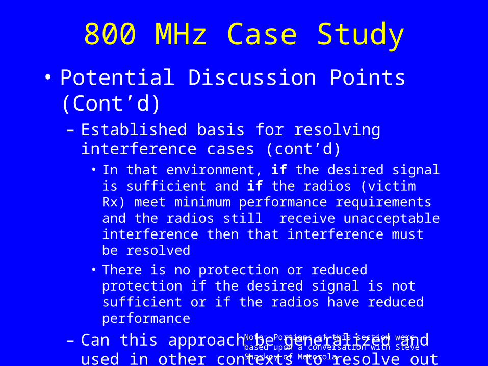
800 MHz Case Study• Potential Discussion Points (Cont’d)
– Established basis for resolving interference cases (cont’d)
• In that environment, if the desired signal is sufficient and if the radios (victim Rx) meet minimum performance requirements and the radios still receive unacceptable interference then that interference must be resolved
• There is no protection or reduced protection if the desired signal is not sufficient or if the radios have reduced performance
– Can this approach be generalized and used in other contexts to resolve out of band interference issues?
– Challenges?
Note: Portions of this section were based upon a conversation with Steve Sharkey of Motorola

Contact Information
Dale N. HatfieldExecutive DirectorSilicon Flatirons Center for Law, Technology, and EntrepreneurshipUniversity of Colorado at Boulder401 UCB - Office 404Boulder, CO 80309Direct Dial: 303-492-6648Email: [email protected] [email protected]


![BY KATE SILVER [ Boulder, Colorado – Home of the Flatirons ]€¦ · Flatirons, this idyllic town, surrounded by green open space and dominated by the University of Colorado, is](https://static.fdocuments.us/doc/165x107/5f068ea67e708231d4189461/by-kate-silver-boulder-colorado-a-home-of-the-flatirons-flatirons-this-idyllic.jpg)