Intro to SAN Capacity Planningt - Demand Tech
15
An Introduction to SAN Capacity Planning Mark B. Friedman Datacore Software 1020 Eighth Avenue South, Suite 6 Naples, FL USA 34102 [email protected] Abstract. Emerging technology that allows the construction of high performance storage area networks (SANs) requires extending existing analytic frameworks that can accurately predict the performance of complex disk subsystems. This paper focuses specifi- cally on two elements of emerging SAN technology: (1) the performance of Fibre Channel links and connecting hubs and switches, and (2) the performance of in-band and out-of-band SAN data management protocols. Traces and timings from benchmarking tests conducted with an in-band SAN data manager product are analyzed and discussed. Understanding this measurement data should enable existing disk modeling approaches to be extended to encompass this new storage technology. Introduction Storage Area Networks (SANs) are constructed around high bandwidth, low latency Fibre Channel (FC) connec- tions between storage peripherals and computer hosts. Exploiting Fibre Channel technology, SANs can be built that interconnect large numbers of host computers and peripheral storage devices. In SANs, storage resources no longer need to be tethered to a specific host computer in an inflexible way that restricts access to those resources. Instead, in a SAN multiple host computers can gain direct access to a common, shared pool of storage resources. Some form of SAN management is naturally necessary to mediate access to shared storage resources. This paper examines two crucial elements of emerging SAN technol- ogy: (1) the performance of Fibre Channel links and connecting hubs and switches; and (2) the performance of in-band and out-of-band SAN data management proto- cols. Ultimately, pulling all these elements into a rigorous conceptual framework for disk performance modeling, such as the one formulated in [1], should allow us to configure, tune, and manage the growth of high perfor- mance storage networks. Because storage area networking using Fibre Channel technology is relatively new, it inevitably raises challenges to storage administrators responsible for their configura- tion and deployment. Fortunately, many of the elements of SAN capacity planning are familiar. Magnetic disk performance is a constant whether configured in a SAN or more conventionally attached to a host computer. Cached RAID disk subsystems, for another example, are also a core component of SANs, raising familiar issues of capacity vs. performance trade-offs. However, Storage Area Networking does introduce some additional hard- ware wrinkles, including optical Fibre Channel links and switched networking topologies that add a new dimension to the analysis. Understanding the performance of these new hardware components is a crucial first step. Another new component associated with SAN technol- ogy that has a performance dimension is the SAN data management protocol. It has become commonplace to describe competing SAN data management protocols as being either in-band or out-of-band. In this paper we will discuss traces and timings from an in-band SAN data manager software product called SANsymphony that executes on a conventional Intel server running the Microsoft Windows 2000 operating system. In-band SAN data management means that some SAN component actively participates in each disk data access operation, redirecting it either to Intel server memory (configured as a cache) or to the appropriate physical device. For a variety of reasons, in-band SAN data management is a superior approach to first generation, out-of-band techniques. Because its data management services are transparent to SAN clients, in-band SAN data managers are much easier to deploy than out-of-band approaches that normally require specific client file system or device driver software and/or hardware modifications. Moreover, as this document will discuss in detail below, relatively inexpensive in-band SAN data managers can provide superior performance using familiar memory- resident caching techniques. [2] What is a SAN? Storage Area Networks are created around Fibre Channel connections linking host computers and storage peripherals such as magnetic disk drives, tape, etc. Figure 1 provides a conceptual view of a SAN, according to this definition. Basically, some number of host computers are linked to a set of storage resources. How the host comput-
Transcript of Intro to SAN Capacity Planningt - Demand Tech

An Introduction to SAN Capacity Planning
Mark B. FriedmanDatacore Software
1020 Eighth Avenue South, Suite 6Naples, FL USA 34102
Abstract.Emerging technology that allows the construction of high performance storage area networks (SANs) requires extending
existing analytic frameworks that can accurately predict the performance of complex disk subsystems. This paper focuses specifi-cally on two elements of emerging SAN technology: (1) the performance of Fibre Channel links and connecting hubs andswitches, and (2) the performance of in-band and out-of-band SAN data management protocols. Traces and timings frombenchmarking tests conducted with an in-band SAN data manager product are analyzed and discussed. Understanding thismeasurement data should enable existing disk modeling approaches to be extended to encompass this new storage technology.
IntroductionStorage Area Networks (SANs) are constructed around
high bandwidth, low latency Fibre Channel (FC) connec-tions between storage peripherals and computer hosts.Exploiting Fibre Channel technology, SANs can be builtthat interconnect large numbers of host computers andperipheral storage devices. In SANs, storage resources nolonger need to be tethered to a specific host computer in aninflexible way that restricts access to those resources.Instead, in a SAN multiple host computers can gain directaccess to a common, shared pool of storage resources.
Some form of SAN management is naturally necessaryto mediate access to shared storage resources. This paperexamines two crucial elements of emerging SAN technol-ogy: (1) the performance of Fibre Channel links andconnecting hubs and switches; and (2) the performance ofin-band and out-of-band SAN data management proto-cols. Ultimately, pulling all these elements into a rigorousconceptual framework for disk performance modeling,such as the one formulated in [1], should allow us toconfigure, tune, and manage the growth of high perfor-mance storage networks.
Because storage area networking using Fibre Channeltechnology is relatively new, it inevitably raises challengesto storage administrators responsible for their configura-tion and deployment. Fortunately, many of the elementsof SAN capacity planning are familiar. Magnetic diskperformance is a constant whether configured in a SAN ormore conventionally attached to a host computer. CachedRAID disk subsystems, for another example, are also acore component of SANs, raising familiar issues ofcapacity vs. performance trade-offs. However, StorageArea Networking does introduce some additional hard-ware wrinkles, including optical Fibre Channel links andswitched networking topologies that add a new dimension
to the analysis. Understanding the performance of thesenew hardware components is a crucial first step.
Another new component associated with SAN technol-ogy that has a performance dimension is the SAN datamanagement protocol. It has become commonplace todescribe competing SAN data management protocols asbeing either in-band or out-of-band.
In this paper we will discuss traces and timings from anin-band SAN data manager software product calledSANsymphony that executes on a conventional Intelserver running the Microsoft Windows 2000 operatingsystem. In-band SAN data management means that someSAN component actively participates in each disk dataaccess operation, redirecting it either to Intel servermemory (configured as a cache) or to the appropriatephysical device. For a variety of reasons, in-band SANdata management is a superior approach to first generation,out-of-band techniques. Because its data managementservices are transparent to SAN clients, in-band SAN datamanagers are much easier to deploy than out-of-bandapproaches that normally require specific client file systemor device driver software and/or hardware modifications.Moreover, as this document will discuss in detail below,relatively inexpensive in-band SAN data managers canprovide superior performance using familiar memory-resident caching techniques. [2]
What is a SAN?Storage Area Networks are created around Fibre
Channel connections linking host computers and storageperipherals such as magnetic disk drives, tape, etc. Figure1 provides a conceptual view of a SAN, according to thisdefinition. Basically, some number of host computers arelinked to a set of storage resources. How the host comput-

ers are configured or how the storage resources they areattached to are configured is immaterial. What matters isthat there is an interconnection fabric that links thesecomponents together, potentially allowing any host toaddress any storage device that is attached to the storagenetwork.
It is not generally understood that installing FibreChannel technology alone does not create a SAN. FibreChannel merely provides the necessary plumbing thatmake SANs possible. Once multiple SAN clients gainaccess to a pool of shared disk resources, some form ofdata management protocol is necessary to mediate accessbetween the clients and the storage devices. Some form ofuser identification and authentication is required to ensurethat SAN clients only access the disks and/or files that theyare authorized to access. If volumes or files are shared, aserialization and locking mechanism is also required topreserve data integrity. If physical storage resources arepooled and some form of virtualization is used to create thelogical volumes and files that SAN clients access, a resourcemanager responsible for allocating and freeing physicalresources is necessary. Virtualization also requires ensuringthat each client’s view of the mapping between logical tophysical devices is current. These essential SAN datamanagement functions all transcend the traditional facilitiesof Fibre Channel and its associated networking hardware.
SANs vs. NAS. SANs based on current technologyhave one additional key requirement, namely that the hostcomputer clients on a SAN address SAN storage re-sources, such as disk drives, directly using the SCSIcommand set. This clearly distinguishes SAN technologyfrom Network-attached storage (NAS) devices, withwhich they are apt to be confused. “SAN” may be “NAS”spelled backwards, but that coincidence is not something
that helps to clarify the fundamental distinction betweenthe two approaches.
In a NAS environment, storage devices are directlyattached or tethered to specific host computers. Thesehosts then permit access to their directly-attached disksusing network-oriented protocols such as nfs, CIFS, orhttp. In NAS, disk access requests are transformed usingnetworking volume and file access protocols that alsospecify matters such as security access and file locking.
Conceptually, a NAS environment looks like Figure 2,showing two computers using networking protocols toestablish remote disk volume and file access. A network-ing client establishes a connection with a file server usingstandard protocols such as SMB (aka CIFS), nfs, or http.These application level protocols run on top of the TCPhost-to-host networking protocol that is responsible forsetting up and managing the network connection betweenhost computers for the duration of a session. Routingpackets from one node on the network to another ishandled by the lower level IP layer, which, in turn runs,on top of a Link Layer that interfaces directly to network-ing hardware.
Because they leverage an existing TCP/IP inter-networking infrastructure, NAS devices are ordinarily easyto deploy. But remote file access mediated by traditionalTCP/IP-based networking protocols has inherent limita-tions, which restrict the environments where NASmachines can provide acceptable levels of service.
Performance considerations distinguish NAS fromSAN, favoring an interconnection technology specificallydesigned for storage. Never optimized for disk access,many aspects of the standard TCP/IP network protocolare far from ideal for storage devices. For example, theEthernet protocol that furnishes the backbone technologyfor Local Area Networking (LANs) uses a maximumtransmission unit (MTU) of 1500 bytes. Meanwhile,SCSI commands transfer data in block-oriented chunks of4 KB or larger. Data intensive applications like digitalvideo streaming often attempt to move data between the
FIGURE 1. A CONCEPTUAL VIEW OF A SAN. IN A SAN, SOME
NUMBER OF HOST COMPUTERS ARE LINKED TO A SET OF STORAGE
RESOURCES.
FIGURE 2. A CONCEPTUAL VIEW OF NAS. STORAGE DEVICES ARE
DIRECTLY ATTACHED TO SPECIFIC HOST COMPUTERS. THESE HOSTS
THEN PERMIT ACCESS TO THEIR DIRECTLY-ATTACHED DISKS USING
NETWORK-ORIENTED PROTOCOLS SUCH AS NFS, CIFS, OR HTTP.
TCP/IPhardware
(switches, routers, etc.)
SMB, nfs, http
TCP
IP
Ethernet
SMB, nfs, http
TCP
IP
Ethernet
Fibre Channelfabric

computer and disk in chunks as large as 1 MB. Breakinglarge chunks of data into MTU-sized packets (a functionof the IP layer) for transmission and then reassemblingsmall packets into larger application-oriented chunks isinefficient and time-consuming. The performance of NASdevices when the SCSI block size is not a good match to theunderlying network MTU is notoriously poor. (For onetypical example, see [3], especially section 9, pages 45-48.)
Another example is the acknowledgement mechanismthat TCP Host sessions use to confirm successful deliveryof each packet sent is unnecessary when computer hostsaccess disk devices. Disk channels are reliable connectionsthat, compared to more transient networking connections,are quite unlikely to fail. Consequently, a significantlymore efficient mechanism can be used that notifies thehost only when errors occur. This explains why most ofthe current industry interest in direct network-attacheddisks revolves around utilizing the IP packet routing layer,bypassing the upper level TCP host-to-host layer.
Considerations such as these dictate that a new,storage-oriented infrastructure is needed to connectassorted computer hosts to assorted disks directly. UnlikeNAS, SANs require constructing a new, separate and distinctnetworking infrastructure built around Fibre Channel links,adaptors, hubs, and switches. The SAN infrastructureconceptually duplicates hardware that currently exists tomake LAN and WAN connections, an overlap in functionthat is only natural since the interconnectivity goals ofboth technologies are quite similar. (In fact, the designersof the Fibre Channel specification deliberately borrowedquite freely from computer networking technology.) Thisduplication of function is unavoidable, however, if SANscapable of virtualization with pooling of shared storageresources are to be constructed. Without belaboring thispoint any further, let’s proceed directly to a discussion ofthe technical capabilities of Fibre Channel technology thatmake this new world of storage area networking possible.
Because both NAS and SAN technology have theirplace, a hybridization process has begun where elementsof NAS and SAN are commingled, blurring the finertechnological differences. Inevitably, we can expect hybriddevices that incorporate elements of both SANs and NAS.A NAS device that internally or externally accesses FibreChannel disks is one form of hybrid. Or, what shall wecall a networking client lacking direct SAN connectivitythat can still access a SAN client’s virtual disks usingnetworking protocols and hardware links. In anotherhybridization example, a high availability SAN storagemanager cluster relies on TCP/IP connectivity to commu-nicate status information to other nodes in the cluster.
Fibre Channel technologyFibre Channel (FC) is a relatively new, standards-based
interface technology that functionally replaces SCSI tolink host computers to disk, tape, and other peripherals.
Compared to the older SCSI parallel bus hardware technol-ogy that it was designed to supercede, the Fibre Channelspecification provides the following extended features:
• Support for high speed serial connections overoptical fiber and copper wire connections
• Support for extended distances (up to 120 km onmulti-mode fiber)
• Extended device addressing (up to 27 or 128addresses on a Fiber Channel-Arbitrated Loopsegment; up to 224 or 16,000,000 unique addresseson a multi-segment FC fabric)
• Redundant channel connections for reliability andfailover
• Dynamic, hot-pluggable optical interfaces
These extended capabilities of Fibre Channel hardwaresparked interest in developing storage area networking(SAN), with the goal of seamlessly allowing host computersto access pooled storage devices sharing an interconnectionfabric. Naturally, once there is direct connectivity betweenmultiple hosts and storage devices, it is no longer possibleto rely on host-centric data access and control protocols. Thisleads to the requirement to develop native SAN datamanagement protocols that perform command and controlfunctions consistent with a distributed environment. Weintend to explore the performance implications of SANdata management protocols in some detail in the body ofthis paper.
SANs also introduce new hardware that provides theconnectivity functions to link multiple host computers topooled storage resources. Managing the many physicalconnections between computers and the storage pool isthe province of switching and routing hardware analogousto LAN hubs, switches, and bridges. Understanding theperformance characteristics of this new link technologyand how that performance is impacted by hardwareconnectivity options is a crucial new aspect of SANconfiguration planning. Below, we will attempt to removesome of the mystery associated with FC by characterizingthe performance of this new hardware.
ConnectivityThe Fibre Channel specification supports three
connection topologies: point-to-point, arbitrated loop,and fabric. Point-to-point connections are simple linksbetween one FC controller and another. For the sake ofwiring convenience, Fibre Channel hubs are available thatsimplify point-to-point interconnectivity. Fibre Channel-Arbitrated Loop (FC-AL) connections support a dual loopconfiguration (for redundancy and failover) capable ofaccessing up to 127 target addresses on a single loop.Switched networks, or the fabric topology, is by far themost popular topology, mainly because it supportsextended addressing to up to 16,000,000 attached devices.The potential for attaching that many host computers and

storage devices to the network accentuates the need forextended data management services for these potentiallyvery large environments.
Switches are the main class of FC network gear that isused to link hosts and devices to a fabric. Similar toEthernet switches, FC fabric switches provide dedicatedvirtual circuits between ports with the full Fibre Channelbandwidth available concurrently for each virtual circuit inuse. In one vendor’s switch implementation, for example,shift registers associated with each port are connected to ahigh bandwidth crossbar circuit. After establishing a virtualcircuit between input and output ports for the duration of apacket transmission, bits that register on the inbound port arepromptly echoed on the outbound port. This kind of highspeed FC switching hardware where the complete virtualcircuit is confined to a single switch adds only about amicrosecond of latency to an FC packet transmission.
Multiple switches can be interconnected or cascaded toextend the scope of the fabric beyond the number of indi-vidual ports that a single switch contains. Switching apacket transmission between cascaded switches introducesadditional complexity due to (1) the potentially longerdistances involved (each km of distance adds about 5microseconds latency to the transmission) and (2) thepotential for contention on Inter-Switch links (ISLs). Due tothe myriad ways that switches can be interconnected, theperformance analysis of cascaded fabric switches grows quitecomplex. Although a full discussion is beyond the scope ofthis paper, interested Readers can review an informativediscussion of this subject in [4].
FC ProtocolSerial protocols look like bit streams on the wire. It is
common practice to transmit bit streams in recoverablesegment called packets, and Fibre Channel is no exceptionto being packet-oriented. Similar to the OSI 7 layermodel that influenced the design of the TCP/IP Internetprotocols, Fibre Channel supports a set of well definedlayers that operate on packets, as illustrated in Figure 3,which is adapted from the official specification.
It should be noted that FC protocol design decisionsreflect fundamental differences between storage areanetworks and conventional TCP/IP-based networking.FC’s deliberate divergence from cherished internetworkingstandards developed with painstaking care over the lasttwenty years is due to the need to operate networks forstorage devices efficiently. Transmissions between hostcomputers and peripheral storage devices demand bothhigh throughput and low latency; they need to be opti-mized for those requirements. Moreover, the networkinglinks used to connect host computers and peripherals,even in fiber-based storage networks that support dynamicand non-disruptive reconfiguration, reflect persistent,durable, and reliable connections. (Host computersgenerally do not tolerate transient state changes that wouldmake a file system periodically appear and disappear.)
Serial protocols can accommodate much highertransmission rates than the parallel bus technology used inSCSI that FC supercedes. During the arbitration phase ofSCSI bus command processing, for example, an electricalcontrol signal must travel up and back on the parallelhardware bus and allow time for target devices to respond.The arbitration phase on a SCSI bus lasts approximately500 microseconds before the SCSI command initiator andtarget are latched. Command processing is followed by aclean-up phase that quiesces the bus in anticipation of thenext transaction. This involves similar bus signaling that alsolasts about 500 microseconds. Delays of this duration weretolerable when the SCSI bus ran at 5, 10 or 20 MB/second.At higher transmission rates, however, more and more of theSCSI bus bandwidth is consumed by this handshaking delay.In addition, the lengthy electrical signaling needed in SCSIto establish and tear down connection was eliminated in theFibre Channel serial protocol.
In contrast to TCP/IP, Fibre Channel pushes packetflow control deep into the interface hardware. The FC2,or Framing Layer, is responsible for generating packets ofthe required size for outbound traffic and for re-assem-bling them on the inbound side. Packets from multipletransmissions can be interleaved, providing for very higheffective data transmission rates. The Framing Layer runsin the interface hardware (both in the Host bus adapterand at the target device), rather than utilizing an externalsoftware stack. An advantage of this approach is that itreduces the number of interrupts that attached hosts mustprocess. Rather than generate a host interrupt each time aframe is received, a Fibre Channel adaptor need onlypresent one interrupt to the host computer at the conclu-sion of a successful Read operation.1
FIGURE 3. THE LAYERS OF THE FIBRE CHANNEL PROTOCOL.
Upper Level Protocol
SCSI IPI-3 HIPPI IP
100 MB/sec Physical Layer
Common Services
Framing Protocol/Flow Control
8B/10B Encode/Decode
Fc4
Fc3
Fc2
Fc1
Fc0
1 In contrast, high-speed networking (gigabit Ethernet or faster) isplagued by the overhead of interrupt processing. See, for example, [5].Each Ethernet packet invokes processing by multiple layers of thecomplex TCP/IP software stack. Processing a 1 Gb Ethernet link usingstandard 1.5 Kb frames would theoretically generates 80,000 hostcomputer interrupts per second that would require processing by the fullTCP/IP software stack.

Another throughput-oriented efficiency results fromthe FC Framing Layer’s guaranteed in-order delivery ofpackets. In-order delivery greatly simplifies the bufferinglogic for the node processing the inbound data stream.Guaranteed delivery in a switched fabric ensures that packetsare never routinely dropped whenever there is contention.The reliable, in-order packet delivery mechanism of FC alsoeliminates the need for both (1) TCP-style acknow-ledgement packets that have an acute impact on effectivedata transmission bandwidth over extended distance linksand (2) complex retransmission time-out (RTO) logic inthe software stack that are necessary to deal with anunreliable delivery service like IP. [6]
As Figure 3 above indicates, the lower Fibre Channellevels were designed to support multiple upper levelprotocols, including both SCSI and IP network traffic.Theoretically, transmitting IP packets over FC links is oneway to achieve interoperability of FC and IP networks. Inaddition, there are currently several industry initiativesattacking the interoperability problem from the oppositedirection by encapsulating SCSI commands in IP packets.The ultimate goal of both exercises is to let a single opticalwiring infrastructure carry traffic to and from both types ofdevices. The convenience factor of having hybrid networkgear that can handle both IP and SCSI traffic appeals toorganizations facing the cost of installing a new, opticalfiber infrastructure. One sobering assessment of thisinevitable convergence is that the performance of hybridnetworks is apt to be less than optimal based on the needto process two workloads with starkly different character-istics. Applications that demand the highest levels ofstorage or networking performance in this brave newworld will be better served when SCSI and IP traffic areconfined to dedicated sub-networks.
Fibre Channel performanceThe role Fibre Channel technology plays in SAN
performance is relatively straightforward. The FibreChannel protocol increases the performance of typicalSCSI command processing by implementing faster links.It also eliminates the lengthy SCSI bus arbitration phase.The result is a peripheral connection technology that
delivers both high bandwidth and low latency. Thissection explores these two aspects of Fibre Channelperformance.
To ease the transition to a new interface technology,Fibre Channel fully supports the existing SCSI commandset. In a SAN, SCSI commands are encapsulated in apacket-oriented protocol designed to support high speedserial links. Currently, the most common form of FibreChannel technology utilizes optical fiber links running at100 MB/sec. Recently, higher speed 200 MB/sec linkshave been introduced. It is also possible to run the FibreChannel protocol over copper wire for short distances.The timing and test results discussed here were allobtained using 100 MB/sec optical FC connections.
Figure 4 below illustrates the timing for a typical 16KB Read request from a SAN client over a 100 MB/secFibre Channel link to a SANsymphony Storage DomainServer (SDS). The timing data here was acquired using aFinisar hardware monitor. A complete 16 KB Readrequest is performed in approximately 330 µsecs. Thecommand execution is broken into a number of differentframes processed in three distinct phases, as illustrated.
Initially, a small frame containing the SCSI Readcommand is processed. The SANsymphony SDS softwareexplicitly responds to the SCSI Read request, translatingthe virtual SCSI disk address known to the client into aphysical address for an SDS-managed disk. The softwarethen searches the SDS data cache for the data requested.On a cache hit, data transfer can begin immediately, andno further delay in processing the Read request is neces-sary. The Command processing phase lasts approximately140 µsecs from the initiation of the request to the firstdata transfer frame that is returned by the SDS in reply.We will explore what happens during that 140 µsecs ofprocessing inside the SDS in a moment.
The Command processing phase is followed by a replythat initiates the data transfer phase. This consists of 16 1024byte data frames that are processed approximately every 10.2µsecs, which corresponds to the 100 MB/sec instantaneoustransfer rate that first generation FC links support. The blockdata transfer phase is followed by a frame that contains theSCSI status that marks the command complete. There is a
FIGURE 4. THREE PHASES PROCESSING A 16 KB SCSI READ COMMAND OVER A 100 MB/SEC FC LINK.
SCSI ReadCommandLength =x’4000’
0 10 20 30 40 50 130 140 150 160 170 180 190 200 210 220 230 240 250 260 270 280 290 300 310 320 330
16 x 1024 Byte Data Frames StatusFrame
140 secs�27 secs�

delay of about 27 µsecs between the last data frame and thetransmission of the status frame.
SCSI Write command processing on Fibre Channelruns slightly slower. There is a similar 140 µsec processingdelay for the initial SCSI Write command request. Asrequired by the Fibre Channel specification, the protocolrequires that the device return an additional setup framethat acknowledges the Write request. In this example, theSDS software impersonating the device generates thissetup frame in reply. Following this frame, there is afurther delay of 30 µsecs at the client before the data to betransferred from the initiator to the target device appearson the link. In the protocol trace, 1 KB data frames thenstart to appear at regular 10.275 µsec intervals. After thelast data frame, there is a final 30 µsec delay until theSANsymphony SDS issues the SCSI status frame indicat-ing successful completion of the request. Note that theSDS posts a successful completion status following receiptof the full data payload. This is known as a fast write tocache. Writes require scheduling an I/O to the diskimmediately to update the permanent copy stored there.SANsymphony software schedules the disk update tooccur immediately, but it is performed asynchronously sothat the SAN client is not delayed for the duration of aphysical disk operation.
Overall, processing the Write request takes about 30µsecs longer than the simpler 16 KB Read request, asillustrated in Figure 5. When the virtual volume isprotected using SANsymphony’s high availability, diskmirroring feature, Write commands are subject to anadditional delay when they are propagated to a standbySDS. When virtual disks are protected by mirroring,successful completion status for Writes is not presenteduntil the write data is present in two SDS caches. Thisapproximately doubles the latency for Write requests.
These timing illustrate the clear performance advantagethat FC holds over the older SCSI parallel bus interfacetechnology. A 16 KB Read or Write command can beprocessed on a Fibre Channel link in roughly the time it
takes for SCSI bus arbitration to occur. SCSI bus arbitra-tion and clean-up phases block all other traffic on the busfor the duration of the lengthy signaling and synchroniza-tion process. In contrast, because FC bit streams arepacket-oriented, it is possible to interleave the packetsfrom multiple commands on an FC link. For example,during the time that one initiator is idle waiting for areply, another initiator can be transferring data. Thecapability to overlap processing of multiple SCSI com-mand leads to very effective utilization of Fibre Channellinks. On a single 100 MB/sec link, for example, usingmultiple initiators, it is no problem sustaining 80 MB/secor better effective data transfer rates. In contrast, effectiveutilization of a SCSI parallel bus reaches only about 50%of the rated bus speed.
The performance characteristics of high bandwidth,low latency Fibre Channel links, along with the speed andcapacity of FC switches, simplifies at least one aspect ofSAN capacity planning. Assuming for a moment that thecost per port for an FC switch is not an obstacle, a SANinfrastructure linking hosts to storage devices with noapparent performance constraints can be constructedwithout much effort. Cascaded switches and long haulconnections are complicating factors, as noted earlier, butwe suspect these are relatively minor concerns in connect-ing most server farms to pooled disk resources today.
In practice, of course, it is not cost effective to dedicatean FC link to every host-disk connection. This leads tothe usual channel configuration decisions and trade-offsinvolving string length and string balancing. Native diskdevice transfer rates remain less than 1/2 the capacity of theFC link. This means that it only takes two or three busydevices (e.g., 3 disks being read in parallel by a multithreadedback-up process) on an FC link to saturate it. So, while itis possible to string together 127 devices on a single FC-AL loop, for example, performance considerations oftendictates shorter string lengths. Avoiding I/O hot spotswithin a complex arrangement of disk and tape devices isalso problematic. Until software can be devised to auto-mate the process, SAN administrators will need torebalance the I/O workload manually across the availablehardware periodically.
SAN data management protocols.SAN data management protocols mediate host
computer access to pooled disk and tape storage resources.It has become commonplace to differentiate between in-band and out-of-band data management. In-band refers toan approach where the data management protocol activelymanipulates each and every storage access operation. Out-of-band refers to an approach where the SAN datamanagement protocol is actively involved only in settingup sessions, and is passive thereafter, unless there is anevent that changes the state of an active session. Oneuseful way to look at the distinction between in-band and
FIGURE 5. A COMPARISON OF THE LATENCY IN PROCESSING 16 KBSCSI READ AND WRITE COMMANDS OVER A 100 MB/SEC FIBRE
CHANNEL LINK.
010
020
030
0400
microseconds
Read
Write
Fiber Channel Latency (16 KB)
SCSI command Write setup Data frames SCSI status

out-of-band data management is to compare them basedon where the data management protocol responsible forvirtual to physical disk translation runs during an I/Ooperation. In out-of-band solutions, virtual:physical disktranslation runs on the client. In in-band solutions, it runson the SAN appliance, transparent to the SAN client.
Out-of-band data management. The most commonout-of-band approach requires that the SAN client accessa SAN metadata controller (SMDC)2 during session setupprior to performing any I/O operations to SAN-managedstorage resources. Volume and/or file metadata in thiscontext refers to the data about disk volumes and files thata SAN manager component must maintain: e.g., how thevirtual volume is mapped to physical disk resources, whichSAN clients are authorized to access which volumes andfiles, what active sessions hold which resources, etc. Oncethe initial request has been authenticated by the SMDC,the appropriate volume and/or file access metadata isreturned to the client, allowing the SAN client to thenaccess managed storage devices directly.
Depending on the approach, having acquired an accesstoken, the client accessing SAN storage proceeds at theeither the physical block or logical file level. Again theseapproaches are distinguished by where on the client thelogical:physical translation function is performed. Filelevel accesses require software inserted into the file systemlayer of the host computer’s I/O manager software stack.Block level access requires that the translation occur in thedisk driver or Host bus adapter software that interfacesdirectly with the hardware.
Figure 6 illustrates the sequence of events that structurean SMDC client access session. The session begins whenthe client requests access to a pooled storage resource (usuallya logical volume or file system). The client then waits whileit has its request authenticated by the metadata controller.The metadata controller eventually furnishes the SANclient with a token that is required to access the disk ordisks involved. This token includes the Fibre Channel andSCSI addressing information that the SAN client needs toaccess the resource directly. Once its request has beenauthenticated, the SAN client proceeds to access thestorage hardware involved directly, as illustrated.
The performance implications of out-of-band datamanagement protocols are two-fold. First, there is latencyassociated with accessing the metadata controller duringsession setup. The extent of this delay is highly dependenton the specific architecture of the SMDC, the contentionfor this machine in the configuration, etc. But, whateverthe specific proprietary implementation, session set-uphandshaking is only performed once at session initializa-tion. Even if the SMDC requires periodic reauthorization
and renewal of the client’s authorization, the performanceimpact of session initialization should still be relativelyminor. So long as SMDC access remains relatively infre-quent, the performance impact of this out-of-band access isminimal. This is not the end of the story, however.
Having obtained the appropriate credentials from theSMDC, the SAN client is able to then issue SCSIcommands directly to SAN disk and tape devices. Themetadata acquired during session initialization providesthe SAN client with the information it needs to accessSAN storage resources directly from that point forward.To accomplish this, the individual SAN client executes afunction that translates virtual device addresses to physicaldevices addresses. So long as SAN virtual address transla-tion runs as a software function executing somewhere onthe SAN client, the performance impact of the SMDCapproach should remain low, adding just a few microsec-onds to device service time. While it is not true that thereis no incremental overhead associated with the SMDCapproach, it is safe to say that the added overhead per I/Ois minimal in most cases. Academic and industry expertsthat champion this approach to SAN data managementmake much of this fact.3 However, this presumed perfor-mance edge has not proven to be the overriding successfactor that its champions have predicted. In fact, the costand administrative burden of maintaining a SAN managedby a metadata controller trumps the performance consid-erations almost every time.
FIGURE 6. THREE PHASES IN SETTING UP A DATA ACCESS SESSION
WITH A SAN METADATA CONTROLLER. THE INITIAL REQUEST FOR
ACCESS (1) IS AUTHENTICATED BY THE SMDC, WHICH RETURNS AN
ACCESS TOKEN TO THE SAN CLIENT (2). WITH THE TOKEN IN HAND,THE SAN CLIENT CAN BEGIN TO ACCESS THE DISK DEVICE DIRECTLY (3).
3 See, e.g., [7]. Dr. Gibson first proposed an architecture for SANmetadata controllers in [8]. For more information on the Gibson’sinfluential approach, see http://www.pdl.cs.cmu.edu/NASD/.
2 Here and elsewhere we adhere to the SAN classification scheme andother terminology attributed to storage industry analyst Randy Kerns ofthe Evaluator Group, www.evaluatorgroup.com.

In the SAN metadata controller approach, the price forminimizing the performance impact is the cost of main-taining client-side software for each and every SAN client.When the SAN is used to interconnect only a few com-puter hosts, maintaining SAN data management softwareon each client may not be prohibitive. But as the numberof SAN clients increases and the SAN is used to intercon-nect hosts running different operating systems, therequirement to distribute and maintain software on eachSAN client grows more burdensome and expensive. Thesoftware installation and maintenance burden associatedwith SAN metadata controllers has slowed down their rateof adoption considerably.
In-band data management. The leading alternative tothe out-of-band SAN metadata controller approach is in-band SAN data management. The in-band approach wasinitially dismissed by many industry observers as somehowtoo intrusive and technically inferior to the “direct” deviceaccess method offered using an SMDC. However, in-band data management protocols do not require SANclient-side software, so they are much easier to deploy.Once deployed, they are also easier to grow and modify.No client software to purchase makes in-band SANs lessexpensive to acquire and dramatically less expensive toadminister. In the hands of capable practitioners, in-bandSAN data management has emerged as the more flexible,more cost-effective, and more easily deployed approach.An in-band implementation can also outperform anSMDC architecture, which is the topic we intend toexplore at some length here.
SAN appliances. There are several ways to implementan in-band SAN data management protocol. One of themost popular is to use a SAN storage appliance, a dedi-cated SAN storage controller of some sort. It has beenrelatively straightforward for vendors of storage processorslike the EMC Symmetrix, IBM Enterprise Storage Server(ESS), or the Xiotech Magnitude to equip these units withfront-end Fibre Channel interfaces and turn them intoserviceable SAN appliances. In this form of SAN appliance,the necessary SAN data management services such asvirtualization run inside the appliance, along with moretraditional storage data management services like cachingand RAID mapping. Running virtual:physical disktranslation inside the appliance makes access to SANstorage resources transparent to SAN clients. Sincechanges applied at the appliance are immediately visible atclients, there is also the benefit of centralized administra-tion. However, this benefit tends to diminish as moreappliances are added to the SAN or appliances fromdifferent vendors are deployed.
Before proceeding to a discussion of the performanceaspects of in-band SAN appliances, it is appropriate toaddress a common point of confusion about them. It may
not be immediately obvious that a storage processoroutfitted with front-end FC interfaces functions as an “in-band” SAN storage manager. However, storage processorshave long relied on in-band data management protocols,redirecting logical volume requests to RAID-mapped diskarrays, for example. Specifically, a standard storageprocessor function allows a storage administrator to groupphysical devices, specify a RAID mapping (RAID 0/1disk striping with disk mirroring, for example, or RAID 5redundancy with a rotated parity disk), and export thatgrouping as a SCSI LUN (Logical Unit Number) that isdirectly addressable by a host computer. Each hostcomputer-generated SCSI command to read or writesome logical disk address must be processed in-band bythe storage processor and translated according to theRAID mapping scheme into an actual physical disklocation. For example, a direct-attached host computersees a SCSI LUN that represents a 72 GB physical disk. Thestorage processor understands that the 72 GB LUN is alogical entity formed by creating a RAID 5 4+1 parity groupusing five 18 GB capacity drives. Logical:physical disktranslation, which is transparent to the attached host, isperformed by a control program inside the storageprocessor that figures out which location on the fivephysical disks associated with the LUN to Read or Write.
The same, effective techniques for transforming hostSCSI commands carry over to current SAN applianceproducts. Perhaps, due to all the public fuss about emerg-ing SAN technology, people expect more from a SANappliance than a simple retooling of conventional storageprocessors to support Fibre Channel interfaces. But, aquick survey of SAN appliances available from the majorhardware vendors shows little architectural differencebetween current products and the previous generation ofstorage processor equipment that could only speak SCSI.
The SAN data management protocol being incorpo-rated into every I/O operation is, on the face of it,intrusive. With in-band protocols, a SAN data controllerprocesses every individual client access request involving aSAN-managed storage device. At a minimum, forexample, logical:physical disk translation occurs in-band.This proven, effective approach is very appropriate forSAN appliances to adopt. Even though in-band redirec-tion of SCSI commands is intrusive, it is performedroutinely by all enterprise-class storage processors. Thisintrusion is justified on several grounds, not the least ofwhich is necessity, allowing storage processors to imple-ment a variety of useful data management services. In thecase of RAID, for example, in-band transformation ofhost SCSI commands to support RAID provides extendeddisk reliability. Necessity being the mother of invention,in-band intrusion is further justified when one of theservices storage processors routinely provide is cachingfrequently accessed data in RAM to improve performance.

As noted above, there are only relatively minor archi-tectural differences between previous generation storageprocessors and current SAN appliances from the samevendor. What architectural changes that have occurredwere motivated by performance considerations raised byhigh bandwidth, low latency Fibre Channel technology.The major engineering challenge storage processorvendors face in transforming older designs into SANappliances is ensuring there is sufficient internal processorspeed and internal bus capacity to handle high-speed FCinterfaces. Storage processors that were originally builtusing a number of small, inexpensive microprocessors(e.g., the Intel i960) designed specifically for real-timeapplications may need a power boost when they encounterFC bit streams. Internal data bandwidth can also be anissue. A recent example is the EMC CLARiiON FC4700that utilizes twin Intel Pentium III 733 MHz micropro-cessors, much faster hardware than the previousgeneration CLARiiONs that used PowerPC chips.
The fact that there are only minor differences betweencurrent SAN appliances and previous generation SCSI-attached storage processors simplifies capacity planning.The newer machines perform similar to the older ones,except that they benefit from faster front-end and internalFC interfaces. As noted earlier, the FC protocol elimi-nates the time consuming SCSI bus arbitration phase.Because it supports packet interleaving, it can sustaineffective data transfers rates that are fully 80% of the totalavailable bandwidth. Finally, it provides faster datatransfer rates clocked at 1 Gb/sec.
A general rule for projecting the performance improve-ment of these subsystems is that so long as internalprocessor speed and bus capacity are not a constraint,storage processor performance scales according to front-end capacity (i.e., FC interface speed) for cache-friendlyworkloads and according to disk speed for write-orientedand cache unfriendly workloads. If you know the through-put capacity of storage processor using slower SCSI orESCON front-end interfaces, it is straightforward to projectthe performance of the same box retrofitted with faster FCinterfaces by factoring in the improvements discussed inFigures 4 and 5 above.
SAN data managers. A second way to implement anin-band SAN data management protocol is to incorporateSAN data management functions into an existing com-puting platform. This approach, which has become knownas a SAN storage manager, is distinguished from a SANappliance by the fact that it is not an extension of anexisting disk storage subsystem. A SAN storage manageris a separate, dedicated component placed betweeninterconnected host computers and disk and tape peripher-als. Below we will have the opportunity to look in detail atthe performance of one SAN storage manager, DatacoreSoftware’s SANsymphony.
Datacore’s alternative to building a SAN storagemanger is a software-only approach that utilizes off-the-shelf Intel server hardware running a standard version ofthe Microsoft Windows 2000 operating system attachedto any variety of standard disk and tape peripherals.Minimum requirements for SANsymphony are an Intelserver with two processors running Windows NT or 2000,at least one FC Host Bus adaptor, and 256 MB of RAM,normally configured as a standalone storage managementmachine. In addition, a cluster of at least two SDS PCsare normally configured for fault tolerance and continuousoperations. With Datacore’s SANsymphony software, it ispossible to create a fully functional SAN storage managerusing common, inexpensive hardware components,including Intel-based servers, Windows 2000-compatibledisk and tape subsystems, and FC Host Bus adaptor(HBA) interface cards.
SANsymphony Storage Domain Servers (SDSes)implement an in-band SAN data management protocol,as illustrated in Figure 7. All client access to pooled diskresources is routed through the SDSes. Similar to a SANappliance, virtual:physical disk translation occurs insidethe SDS. Data access requests are then either satisfiedfrom internal server RAM configured as a cache or an I/Oto disk scheduled by the SDS directly. (Functionally, thisis quite similar to what goes on inside a SAN appliance.) Asindicated, multiple SDSes can be configured into a N+1fault tolerant cluster. An SDS cluster provides fault-tolerant disk mirroring with automatic failover to asurviving node or mirrored disk.
Unlike conventional storage processors that are avail-able in a limited variety of standard configurations, aSANsymphony Storage Domain Server (SDS) can beassembled from a wide range of equipment alternatives. Infact, the sheer number of hardware alternatives to considercan be daunting, ranging from simple 2-way Intel servers to4 and 8-way machines with 4 GB or more of RAM. Besidessizing the server machine where SANsymphony runs, thecapacity planner must also decide (1) how to configure theattached disk subsystem – the amount of disk capacity,
FIGURE 7. AN IN-BAND SANSYMPHONY STORAGE DOMAIN SERVER.
Fibre Channel
SAN Clients
Pooled Storage Resources
StorageDomainServers

number of disk actuators (devices), RAID mapping, stringdepth, internal pathing, etc. – and (2) how to configurethe FC switched fabric.
Below, we will discuss sizing a SANsymphony Intelserver, focusing specifically on the areas of processorspeed, number of processors, and PCI bus bandwidth.
The I/O capacity of an SDSBecause the SANsymphony SAN storage manager
software runs on a standard Intel-based server, theperformance and sizing considerations for an SDS areidentical to the ones that arise with standard Windows2000 Intel application servers. This allows us to make use ofstandard performance and tuning tools that operate in thatenvironment. We can also draw on existing expertise inWindows 2000 performance topics.4 For SANsymphonyStorage Domain Server sizing, this general knowledge ofIntel server hardware and Windows 2000 operatingsystem performance needs to be augmented by specificexpertise in the operation of the SANsymphony software.
For the sake of simplicity, in this document we willassume that all FC connections between SAN clients,SAN-managed disks, and SANsymphony SDS machinescan always be made using a single Fibre Channel switch toeliminate from consideration the complexity cascadingfabric switches introduces. Given the availability ofswitching gear capable of packaging as many as 256 portsin a single unit, this appears to be a reasonable simplifyingassumption.
Rather than discuss SANsymphony performance in theabstract, we will illustrate the discussion with measurementdata obtained from exercising an SDS in a benchmarkingtest environment. We conducted a series of benchmarks,only some of which space permits describing below, in anattempt to characterize SANsymphony performance over abroad range of conditions. We will try to place themeasurements we obtained into a conceptual frameworkthat allows you to generalize from these specific results.
Benchmark environment. We obtained all the mea-surements discussed here from a single SDS node runninga prototype of SANsymphony version 5. The SDSmachine was a 4-way 550 MHz Intel server runningWindows 2000 with Service Pack 1 installed. The servercontained three separate PCI buses, all running at 33MHz. Two of the buses supported 32-bit cards, while thethird could handle PCI-2 64-bit cards. The SDS con-tained 9 QLogic 2200 FC adaptors. The configuration ofthis SDS machine is depicted in Figure 8. Seven Intel
clients, all running Windows 2000 on 2-way 300 MHzworkstations, were attached to the SAN. Each clientcontained a single QLogic 2200.
Two racks of 10 Eurologic SANbloc disks featuringSeagate 10,000 RPM Cheetah FC drives were used to createSAN client disks. The SANsymphony SDS server, Intelclients, and JBOD disks were all interconnected using a 32-port inRange fabric switch. Using SANsymphony’sSANManager administrative tool, we created 14 virtualvolumes, each on a dedicated physical disk, and assignedthem two at a time to the SAN clients. We installed theIntel Iometer disk benchmarking utility on one of theclient machines and the remote Dynamo benchmarkingagent on the remaining six clients. The SDS machine andthe SAN clients were all instrumented using PerformanceSeNTry from Demand Technology Software, performingdata collection every 10 seconds. The Windows 2000defaults for diskperf were used, collecting performancestatistics for Physical Disk data only. Besides disk perfor-mance, we also collected data at the system, process, andnetworking level.
In addition, we collected SANsymphony internalperformance statistics, which are available as standardWindows 2000 performance Objects and Counters.SANsymphony provides extensive measurements on SDSthroughput, cache effectiveness, and other areas ofinterest. Understanding the SANsymphony performancestatistics requires some knowledge of the internal architec-ture of the software, a topic we explore below.
SDS software architecture. A SANsymphony StorageDomain Server is a conventional Intel server runningWindows 2000 and the SANsymphony software packagethat allows the server to function as a dedicated in-bandSAN storage manager. The SDS software architecture isconventionally represented as a stack where each layer
FIGURE 8. THE CONFIGURATION OF THE SDS SERVER USED IN THE
BENCHMARK TESTS.
4 X 550 MHz Pentium III
System bus
PC
I 1:
33
MH
z X
4 Qlogic 2200HBAs
PC
I 2:
33
MH
z X
8
Qlogic 2200HBAs
4 Microsoft includes a performance and tuning applet called SystemMonitor with every version of the Windows 2000 operating system.Additional Windows 2000 performance tools and documentation areavailable in the Windows 2000 Resource Kit. [9] is an excellent generalpurpose technical references on Windows 2000 OS internals. Specifictechnical references for Windows 2000 server performance, tuning, andcapacity planning topics are [10] and [11].

optionally operates in sequence on SAN client I/Orequests, as depicted in Figure 9.
Dedicated kernel threads with operating system levelprivileges run the stack. They begin by interrogating theFibre Channel interface cards installed in the SDS,capturing individual SAN client I/O requests, andoperating on them. To achieve higher levels of perfor-mance than is otherwise possible on an all-purposecomputing platform like Windows 2000, SANsymphonyuses polling, where its kernel threads run continuouslyinterrogating the Fibre Channel Host bus adaptor inter-face cards, constantly looking for work. An FC HBApolling thread is significantly more responsive than aninterrupt-driven mechanism that is better behaved in ageneral purpose computing environment. Because pollingprovides more predictable device service time, it is thetechnique used in most real-time environments, includingdedicated communications and storage controllers. Of course,polling is less efficient so it is not the approach used onservers designed for general purpose computing. Users arecautioned to run SANsymphony on a machine that isdedicated to running the SDS, which is a commonsense wayto deploy the software anyway.
Even though it uses polling, the SANsymphonysoftware is designed to co-exist reasonably well with otherapplications that might be running on the same Windows2000 server. In practice, these other applications are likely
to be limited to things like the SANsymphony GUI,performance and storage resource monitoring, and nativedisk-to-tape backup utilities. SANsymphony creates amaximum of n-1 polling threads where n is the number ofprocessors available for use so there is always someresidual capacity available for other applications. At nopoint will SANsymphony ever take over all the processorsin a standard Win2K symmetric multiprocessing configu-ration, always leaving at least one processor available forassorted Windows 2000 housekeeping functions. Using anadaptive mechanism that recognizes when client I/Orequests are likely to begin queuing, SANsymphony startswith one dedicated polling thread, but will then automati-cally dispatch additional polling threads as the I/Oworkload increases. At any one time, the number ofSANsymphony kernel threads that are dispatched variesbased on the load. In case the remaining Win2K non-Fibre Channel initiated processing load is constricted on asingle processor, the maximum number of SANsymphonypolling threads can also be configured manually.
Whenever an SDS polling thread determines that anFC interface card has a request outstanding, it is processedin-line by the kernel thread. As indicated in the diagram,the FC polling threads fields both initiator and targetSCSI device requests. SAN clients issue I/O requests tovirtual disk targets, which are indistinguishable fromordinary SCSI physical disks. These requests are inter-cepted and interpreted by SANsymphony’s Target Modeemulator software, which impersonates the physical diskentity served up by the SDS. Executing the next layer ofthe SANsymphony software stack, the thread thenauthenticates a request to Read or Write a SANsymphonyvirtual disk. If valid, the request is processed by thememory caching layer. If the data requested is alreadyresident in memory, it is a cache hit and the client I/Orequest is processed immediately.
On a Read cache miss, the SANsymphony kernel threadcreates a standard I/O Request Packet (IRP) that is passed tothe native Windows 2000 I/O Manager to read data fromthe associated physical disk. This allows SANsymphony tomanage any disk device that can be directly attached to theSDS, including native SCSI disks. The data requested iscopied first into cache memory and then returned to theSAN client across the Fibre Channel link.
On a Write, the request is passed through to a faulttolerant layer that supports both synchronous and asyn-chronous disk mirroring using an active link to anothernode in the SDS cluster. The fault tolerant layer isresponsible for keeping the mirrored SDS node and diskin sync with the original, so it schedules an I/O to theother SDS. Once a copy of the data is safely resident intwo SDS caches, the Target mode driver signals the SANclient that the Write request was successful. Meanwhile,both SDS nodes schedule a physical disk update to hardenthe changed data on auxiliary storage as soon as possible.
FIGURE 9. THE LAYERED ARCHITECTURE OF THE SANSYMPHONY
SOFTWARE STACK.
SAN client
I/O request
Initator/Target Emulator
FC Adapter Polling Threads
Security
Fault Tolerance
Data Cache
SANsymphony
File System Driver
Disk Driver
Disk perf (measurement)
SCSI miniport
FC Adapter driver
Native Win2K I/O Manager
Processor consumption. First, let’s look at processorconsumption for various SANsymphony functions on anSDS node. We will look at both best case performance whenthe SDS has little to do except poll its Fibre Channelinterface cards looking for work and worst case performancewhen the SDS is serving up small Read I/O requests fromcache. The latter operation, which leads to the highest I/Orates, is the most CPU intensive of any SANsymphonyfunction.
When SAN clients are idle and the Fibre Channelinterface polling engines on the benchmark machine havenothing to do except look for work, SANsymphonyrunning on our benchmark machine recorded slightlymore than 375,000 unproductive polls/sec. That worksout to one kernel thread checking a Fibre Channelinterface card every 2.66 µsecs. Except for the activityassociated with the polling thread, the system was other-wise idle. The overall CPU utilization for the system wasjust over 25%, reflecting the relentless polling activity andvery little else (except for active measurement tasks). This2.66 µsecs of delay associated with an unproductive devicepolling sequence represents the minimum latency of a FCinterface request.
Now let’s look at the timing of a successful pollingoperation. With seven SAN clients issuing small block512-byte requests that could be satisfied from cache,SANsymphony increased the number of polling threads tothe maximum level of three on the 4-way 550 MHz testmachine. Together, with three polling threads active, theSDS machine was able to process about 40,000 I/Orequests per second. At 40,000 IOPS, SANsymphonyrecorded 80,000 productive polls. Each I/O requestprocessed by the SDS evidently required two successfulFC interface polls – one to accept the client’s originalRead request and a second after the data was transferredfrom cache memory back across the FC link to the client.
In addition to the productive polls, the polling enginesstill managed to issue more than 31,000 unproductive
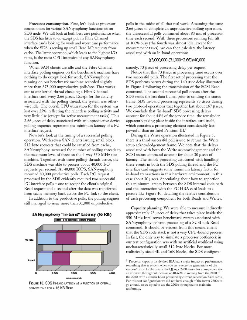
FIGURE 10. SDS IN-BAND LATENCY AS A FUNCTION OF OVERALL
SERVICE TIME FOR A 16 KB READ.
polls in the midst of all that real work. Assuming the same2.66 µsecs to complete an unproductive polling operation,the unsuccessful polls consumed about 83 ms. of processortime each second. With three processors running full tiltat 100% busy (the fourth was almost idle, except formeasurement tasks), we can then calculate the latencyassociated with an in-band operation:
((3,000,000 - (31,000 * 2.66)) / 40,000
namely, 73 µsecs of processing delay per request.Notice that this 73 µsecs in processing time occurs over
two successful polls. The first set of processing that theSDS performs occurs during the 140 µsec delay illustratedin Figure 4 following the transmission of the SCSI Readcommand. The second successful poll occurs after theSDS sends the last data frame, prior to sending the statusframe. SDS in-band processing represents 73 µsecs duringtwo protocol operations that together last about 167 µsecs.We conclude that “in-band” SDS processing delaysaccount for about 44% of the service time, the remainderapparently taking place inside the interface card itself,which contains a processing element considerably lesspowerful than an Intel Pentium III.5
During the Write operation illustrated in Figure 5,there is a third successful poll issued to return the Writesetup acknowledgement frame. We note that the delaysassociated with both the Write acknowledgement and theSCSI status command account for about 30 µsecs oflatency. The simple processing associated with handlingthese events in both the SDS polling thread and the FCinterface card suggests some minimum latency factor forin-band transactions in this hardware environment, in thiscase about 30 µsecs. Speculating about how to apportionthis minimum latency between the SDS internal code pathand the interaction with the FC HBA card leads to apicture like Figure 10, detailing the relative contributionof each processing component for both Reads and Writes.
Capacity planning. We were able to measure indirectlyapproximately 73 µsecs of delay that takes place inside the550 MHz Intel server benchmark system associated withSANsymphony in-band processing of a SCSI disk Readcommand. It should be evident from this measurementthat the SDS code stack is not a very CPU-bound process.In fact, the only way to simulate a processor bottleneck inour test configuration was with an artificial workload usinguncharacteristically small 512-byte blocks. For morerealistically sized 4K and 16K blocks, the SDS configura-
5 Processor capacity inside the HBA has a major impact on performance,something that is evident when you test successive generations of thevendors’ cards. In the case of the QLogic 2x00 series, for example, we sawan effective throughput increase of 40-60% in moving from the 2100 tothe 2200, with a similar boost provided by current generation 2300 cards.For this test configuration we did not have enough of the newer 2300s togo around, so we opted to use the 2200s throughout to maintainuniformity.

tion bottleneck quickly shifts to other resources, as we willdiscuss in a moment.
It is worth noting that the SDS internal processingdelay should scale with the speed of the processor on theSDS server. On an Intel server equipped with 1 GHzengines, for example, we expect that the in-band process-ing delay would drop below 40 µsecs. On today’s top ofthe line 1.7 GHz processors, latency falls further to below24 µsecs per I/O operation. At these faster processingspeeds, it becomes even more important to step up to thelatest generation Fibre Channel interface cards to take fulladvantage of faster CPUs. In Figure 11, we project thelatency for a 16 KB Read request for next generationhardware, upgrading first to a 1.7 GHz processor and thenupgrading to the 200 MB/sec FC HBAs that are justbeginning to appear. We project that SAN-symphonytotal device service time can be reduced a little over 50%using next generation Intel and FC hardware.
This is also a good place to remark upon some of theinternal statistics that the SANsymphony softwaremaintains. One noteworthy measurement to track in thecurrent context is the rate of productive polls, calculated as
Productive polls/sec * 100 /(Productive polls/sec + Unproductive polls/sec)
Internally, SANsymphony calculates this ratio every fewseconds to determine whether sufficient polling threadsare active. When the rate of productive polls rises to 50%,SANsymphony will dispatch another polling thread, up tothe maximum number of polling threads permitted (oneless than the number of processors). As a configuration ruleof thumb, if the rate of productive polls remains above 50%and SANsymphony is running the maximum number ofpolling threads for an extended period of time, there is aCPU capacity constraint. In this benchmark test, for instance,the rate of productive polls was 72%. Configuring additionalengines, faster engines, or some combination of both iswarranted under these circumstances.
SDS scalability. Because the CPU processing load ofan SDS in-band SAN storage manager is modest and it isrelatively easy to procure fast Intel engines, users of aSANsymphony SDS are not likely to encounter seriousprocessor bottlenecks. Testing with more realistically sized4 and 16 KB blocks, the potential bottleneck shifts tointernal PCI bus bandwidth for cache-friendly Readworkloads and to the attached disk subsystem for Writesand very cache-unfriendly workloads. These performanceexpectations are common to all SAN appliances, as notedearlier. The chart below in Figure 12 highlights thesecritical considerations. Let’s look at the impact of PCI busbandwidth first.
The PC Server used in this testing was equipped withone 33 MHz 64-bit PCI version 2 bus and two standard33 MHz 32-bit PCI buses. The server was populated with9 QLogic 2200 HBAs arranged three deep on each PCIbus, as illustrated back in Figure 8. The results in Figure12 summarize a series of tests we performed usingidentical workloads, while varying the number of HBAs(and PCI buses) involved. Results showing both maxi-mum I/O rates (achieved using 512-byte blocks) andthroughput (using 16 KB blocks) are shown.
In the first test series, the SDS server was set to useonly one FC HBA for Target mode requests – remember,Target mode refers to SAN client requests to accessSANsymphony virtual disks. This HBA was plugged intoone of the available 32-bit buses, by the way. A secondHBA was enabled to provide connectivity to the EurologicFC disk arrays. Because we were not interested in spot-lighting any disk subsystem performance issues at thistime, we maintained a single FC back-end connectionthroughout all tests. We should note that the FC link tothe disks was dormant anyway during this series of testsbecause we artificially restricted the workload to fit in theserver’s memory-resident cache. There was almost no needto access the back-end disks.
This first scenario simulates running the SANsymphonystorage manager software on a low cost Intel serverequipped with a single PCI bus. This basic configurationreached almost 78 MB/sec throughput using 16 KBblocks. It reached a maximum I/O rate near 6800 I/Osper second with 512-byte blocks.
In the second series of tests, we enabled a second HBAon the first 32-bit PCI bus and added two HBAs thatwere plugged into the faster 64-bit slot (for a total of fourfront-end interfaces). This scenario simulates runningSANsymphony on a higher-priced dual PCI-bus server.Note the impact of doubling the PCI bandwidth and theeffect of doubling up on the number of HBAs configuredper bus. Both the I/O rate and maximum throughputalmost tripled to 18,000 I/Os per second and 210 MB/secthroughput.
In the third scenario, we enabled all eight availableHBAs for SAN client connections, with two configuredFIGURE 11. PROJECTING SANSYMPHONY PERFORMANCE ON NEXT
GENERATION PC AND FC HBA HARDWARE.
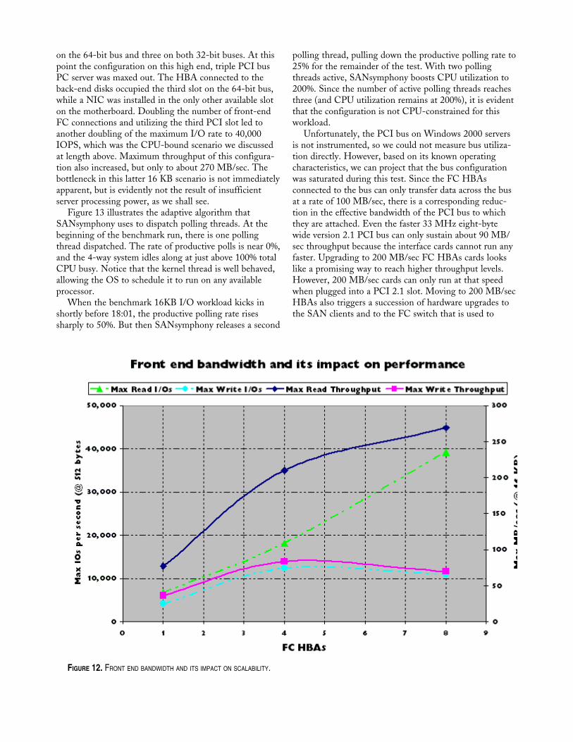
on the 64-bit bus and three on both 32-bit buses. At thispoint the configuration on this high end, triple PCI busPC server was maxed out. The HBA connected to theback-end disks occupied the third slot on the 64-bit bus,while a NIC was installed in the only other available sloton the motherboard. Doubling the number of front-endFC connections and utilizing the third PCI slot led toanother doubling of the maximum I/O rate to 40,000IOPS, which was the CPU-bound scenario we discussedat length above. Maximum throughput of this configura-tion also increased, but only to about 270 MB/sec. Thebottleneck in this latter 16 KB scenario is not immediatelyapparent, but is evidently not the result of insufficientserver processing power, as we shall see.
Figure 13 illustrates the adaptive algorithm thatSANsymphony uses to dispatch polling threads. At thebeginning of the benchmark run, there is one pollingthread dispatched. The rate of productive polls is near 0%,and the 4-way system idles along at just above 100% totalCPU busy. Notice that the kernel thread is well behaved,allowing the OS to schedule it to run on any availableprocessor.
When the benchmark 16KB I/O workload kicks inshortly before 18:01, the productive polling rate risessharply to 50%. But then SANsymphony releases a second
polling thread, pulling down the productive polling rate to25% for the remainder of the test. With two pollingthreads active, SANsymphony boosts CPU utilization to200%. Since the number of active polling threads reachesthree (and CPU utilization remains at 200%), it is evidentthat the configuration is not CPU-constrained for thisworkload.
Unfortunately, the PCI bus on Windows 2000 serversis not instrumented, so we could not measure bus utiliza-tion directly. However, based on its known operatingcharacteristics, we can project that the bus configurationwas saturated during this test. Since the FC HBAsconnected to the bus can only transfer data across the busat a rate of 100 MB/sec, there is a corresponding reduc-tion in the effective bandwidth of the PCI bus to whichthey are attached. Even the faster 33 MHz eight-bytewide version 2.1 PCI bus can only sustain about 90 MB/sec throughput because the interface cards cannot run anyfaster. Upgrading to 200 MB/sec FC HBAs cards lookslike a promising way to reach higher throughput levels.However, 200 MB/sec cards can only run at that speedwhen plugged into a PCI 2.1 slot. Moving to 200 MB/secHBAs also triggers a succession of hardware upgrades tothe SAN clients and to the FC switch that is used to
FIGURE 12. FRONT END BANDWIDTH AND ITS IMPACT ON SCALABILITY.

interconnect them before higher throughput rates can beattained in any configuration.
Conclusion.This paper discusses basic capacity planning consider-
ations for popular forms of in-band and out-of-band SANdata management protocols. We were able to present anddiscuss performance data from a series of benchmark testsdesigned to clarify configuration and tuning issues involv-ing SANsymphony Storage Domain Servers, an in-bandSAN storage manager. Because SANsymphony software runson standard Intel server hardware running the MicrosoftWindows 2000 operating system, its performance issues aresimilar to other Intel server workloads. The availability ofprofessional quality performance measurement tools forthe Windows 2000 platform, along with the expertise inknowing how to use them, makes it possible to explorethese performance issues in some detail.
For a typical 16 KB block Read satisfied from SANsymphonymemory-resident cache, we measured a 330 µsec deviceservice time, broken down into three distinct commandprocessing phases associated with the Fibre Channel serialprotocol. Of the total 330 µsecs of elapsed SCSI targetdevice service time, about half involved transfer of the 16KB data payload, while the other half was due to process-ing by the FC interface card and the SDS software stack.For the 4-way 550 MHz PC used for this series of tests,SDS software accounted for just 73 µsec out of the total330 µsec latency that was recorded. The in-band delayexperienced by SAN clients accessing a virtual disk poweredby a moderate cost SANsymphony appliance compares
FIGURE 13. POLLING EFFECTIVENESS VS. CPU CONSUMPTION FOR
THE 16 KB READ TEST, ILLUSTRATING THE ADAPTIVE MECHANISM
SANSYMPHONY USES TO SCHEDULE FC INTERFACE POLLING THREADS.
favorably with the fastest(and most expensive) FC-enabled storage processorsavailable.
Since the SDS softwarestack requires only modestamounts of CPU power,realistic I/O workloads arefar from compute-bound onwidely available Intel-basedservers. As the benchmarksresults from tests where weincreased the number of FCinterface boards and PCIbuses used in the sampleconfiguration showed,SANsymphony perfor-mance scales in apredictable manner with thenumber of HBAs and theinternal bus bandwidth ofthe server machine.
References[1] Brandwajn, Alexandre, “A study of Cached RAID-5 I/O,”
CMG Proceedings, December, 1994.[2] McNutt, Bruce, The fractal structure of data reference: applica-
tions to memory hierarchy. Boston: Kluwer AcademicPublishers, 2000.
[3] Chung, et. Al., “Windows 2000 Disk I/O Performance,”Microsoft Research Technical Report MS-TR-2000-55,available at ftp://ftp.research.microsoft.com/pub/tr/tr-2000-55.pdf.
[4] Evio Valdevit, “Cascading in Fibre Channel: how to build amulti-switch fabric,” Brocade Communications Systems,available at http://www.brocade.com/SAN/white_papers/pdf/Cascading.pdf.
[5] John Curtis, “In defense of Jumbo Frames,” NetworkWorld,August 10, 1998.
[6] Peterson and Davie, Computer Networks, San Francisco, CA:Morgan Kaufmann, 1996.
[7] Gibson and van Meter, “Network-attached storage architec-ture,” Communications of the ACM, November 2000.
[8] Garth Gibson, “A Case for Network-Attached Secure Disks.”Carnegie-Mellon Technical Report, 1996.
[9] Solomon and Russinovich, Inside Windows 2000, Redmond,WA: Microsoft Press, 2000.
[10] Friedman and Pentakalos, Windows 2000 Performance Guide,Boston, MA: O’Reilly Associates, 2001.
[11] Curt Aubley, Tuning and Sizing Windows 2000, EnglewoodCliffs, NJ: Prentice-Hall, 2001.