intro to Insulation coordination
35
INSULATION COORDINATION - a small overview S. POORNIMA, RESEARCH SCHOLAR
-
Upload
poornima-sridaran -
Category
Documents
-
view
387 -
download
35
description
Intro to insulation coordination
Transcript of intro to Insulation coordination

INSULATION COORDINATION
- a small overview
S. POORNIMA, RESEARCH SCHOLAR

Why Insulation Coordination?
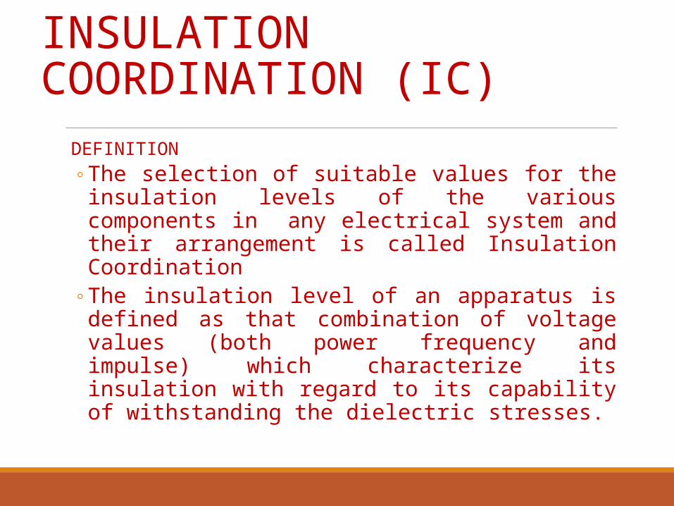
INSULATION COORDINATION (IC)
DEFINITION The selection of suitable values for the insulation levels of
the various components in any electrical system and their arrangement is called Insulation Coordination
The insulation level of an apparatus is defined as that combination of voltage values (both power frequency and impulse) which characterize its insulation with regard to its capability of withstanding the dielectric stresses.

IC ensuresInsulation provided shall withstand all normal working stresses and a majority of abnormal stressesThe efficient discharge of overvoltages due to internal and external causesBreakdown shall occur only due to external flashover.The position at which breakdown occurs shall be those where breakdown may cause no or comparatively little damage

IC involves Determination of line insulation Selection of Basic Impulse Insulation level and insulation levels of other equipment Selection of lightning arrestors
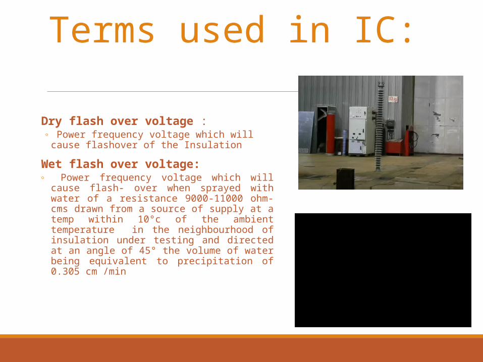
Terms used in IC:
Dry flash over voltage : Power frequency voltage which will cause
flashover of the Insulation
Wet flash over voltage: Power frequency voltage which will cause
flash- over when sprayed with water of a resistance 9000-11000 ohm-cms drawn from a source of supply at a temp within 10°c of the ambient temperature in the neighbourhood of insulation under testing and directed at an angle of 45° the volume of water being equivalent to precipitation of 0.305 cm /min
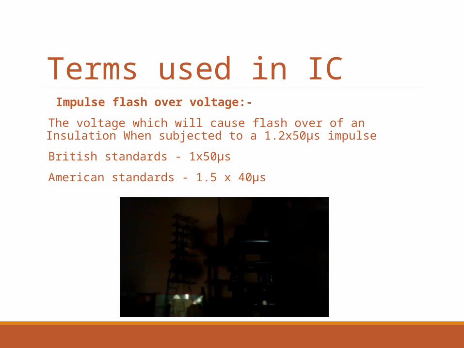
Terms used in IC Impulse flash over voltage:-
The voltage which will cause flash over of an Insulation When subjected to a 1.2x50µs impulse
British standards - 1x50µs
American standards - 1.5 x 40µs

Terms used in IC Basic Insulation level :-The crest voltage of standard wave that will not cause flashover of the insulation is referred to as “Basic insulation level”Basic impulse insulation voltages are reference levels expressed in impulse crest voltage with a standard wave not longer than 1.2x50 µs (Indian standards)Equipment insulation as tested shall be equal or above the BIL

Impulse spark over volt- time characteristic
This characteristic is obtained by plotting Time which elapses between the moment the
voltage wave is applied and the moment of spark over on abscissa
Voltage at the movement of spark over
(i) Occurring on the wave front (ii) Occurring on the wave peaks
(iii) Crest of the voltage for spark over occurring on the wave tail

Impulse spark over volt- time characteristic -contd.
This characteristic is established by means of a 1/50 impulse wave
A line drawn meeting the three B/D values is the characteristic
Proper insulation co-ordination will ensure that the voltage time Curve of any equipment will lie above the volt -time curve of the protective equipment, say, Lightning arrestor
The overvoltage factor (transient voltage amplitude/operating voltage ratio) varies between 1.2 and 1.5.

A) LINE INSULATIONExtra high voltage line can be made lightning proof by Efficient shielding
Transmission lines up to 220kV 30°400 kV at and above 20°
Low tower footing resistance equal to or less than 10 ohmsLine insulation shall be sufficient to prevent a flashover from the power-frequency over voltages and Switching Surges.It shall take into consideration the local unfavourable circumstances which decrease the flash over voltage (rain, dirt, Insulation pollution etc.,)

OVER VOLTAGE FACTORS
Line Voltages
Switching Surge flash over
Power frequency flash over (Dry & Wet)
220kV 6.5 Vpn 3.0
400kV 5.0 Vpn 3.3
Vpn = Phase to Neutral Voltage (rms)
Add one or two more Insulators for each string.

OVER VOLTAGE FACTORS—Contd. -To take care of one disc in the string becoming defective. -Facilitate hot line maintenance Up to 220 kV Line – 1 disc for each string 400 kV Line – 2 discs for each string

FLASH OVER VOLATAGE(FOV) OF DISCS 254 X 145 mm
NO OF DISCS
DRY FOV
( kV rms)
WET FOV
( kV rms)
Impulse FOV (Standard full wave)
( kV rms)
9 540 375 860
10 590 415 945
14 785 565 1265
15 830 600 1345
25 1280 900 2145
7 435 295 695

RECOMMENDED INSULATION LEVEL OF LINE
Normal system Voltage
Vpn
In kV(Vph/√3)
Switching over volt. (Wet) kV *
No of discs required
132kV 76 76 x6.5=495 5
220kV 127 127x6.5=825 9
400kV 231 231x5=1755 13
* Compared with Impulse FOV (Value)

RECOMMENDED INSULATION LEVEL OF LINE—contd.
Normal system Voltage
Vpn
In kVPower freq.
over volt (wet)
(kVrms)
No. of
discs req.
No. of discs
recom.
As per practice
132kV 76 76x3=228 6 7 9/10
220kV 127 127x3=381 10 11 13/14
400kV 231 231x3=762 20 22 23/24

Example Tower footing resistance 10ohms
severest lightning discharge 50kA (rms)
Impulse strength of Insulation=√2x50x10³x10=700kV
As per the standard table for 7 discs, the impulse FOV ( kVp =695kVp)
For better performance tower footing resistance shall be brought down for 132kV is 7 ohms

Co-ordination of line Insulation and Sub-Station InsulationLine Insulation is not directly related to the Insulation of equipment within the Sub-Station.Impulse flash over voltage of line Insulation determine the highest surge voltage that can travel into the sub-station.Current through lighting arrestor can be calculated from
Surge impedance of line Surge voltage arriving over the line
Discharge voltage of the LA on that current is the basic protective level of the substation equipment.Discharge voltage across LA varies with surge current.Overhead shielding ground wires and tower footing resistance protects the line from the impulse surges entering the station.

B) BASIC INSULATION LEVEL AS PER IS (2165 – 1962)
Nominal system volt kV (rms)
Highest system volt kV (rms)
Impulse withstand volt kVp for test
One minute power frequent volt kV (rms)
Full insulation
Reduced insulation
Full insulation
Reduced insulation
132 kV 145 650 550 275 230
220 kV 245 1050 900 460 395
400 kV 420 1550 680
1425 630
Reduced insulation is used where system is effectively earthed.

B) INSULATION LEVELS OF EQUIPMENT Transformers, Isolators, Instrument Transformers are manufactured for the standard Insulation level. Some times transformers, are manufactured for one step lower insulation level for the sake of economy. (LAs will be designed for a still lower level) Where LAs are provided right on the top of the transformer, some of the equipment may lie well out side the protective zone of the LA.

INSULATION LEVELS OF EQUIPMENTProtective zone is determined based on
With stand level of equipment Discharge volt of LA Distance between LA and equipment.Such equipment shall be designed for one step higher BIL.Generally BIL of substation equipment other than transformer are
designed for10% higher BIL than that of Transformer .
BIL of Open poles of a disconnect switch shall be 10 to 15% higher than that provided between poles and earth.

c) Lightning Arrester selection
1. To determine the magnitude of the power frequency phase to ground voltage expected at the proposed arrester location during phase to ground fault, or other abnormal conditions which cause higher voltages to ground than normal.
2. To make a tentative selection of the power frequency voltage rating of the arrester. This selection may have to be reconsidered after step (6) is completed.
3. To select the impulse current likely to be discharged through the arrester.
4. To determine the maximum arrester discharge voltage for the impulse current and type of arrester selected.
5. To establish the full-wave impulse voltage withstand level of the equipment to be protected.
6. To make certain that the maximum arrester discharge voltage is below the full wave impulse, withstand level of the equipment insulation to be protected, by adequate margin.
7. To establish the separation limit between the arrester and the equipment to be protected.

Step1: Power System overvoltages
EHV system must be designed to operate under stresses associated not only with normal operating power frequency voltage but also those caused by transient over voltage.
These transient over voltage rise principally from lightning over voltage and switching operations
The former is predominant in system at 100 kV and below whereas Switching over voltage are of concern in system at 220 kV and above

INSULATION CO-ORDINATIONOver Voltage
Let Un = line to line normal RMS voltage Let Um = Rated highest system voltage rms line to line
√2 Un / √ 3 = Peak of rms voltage phase to ground for nominal system voltage
√2 Um / √ 3 = Peak of rms voltage phase to ground voltage for highest system voltage
Any voltage higher than √ 2/ √ 3 Um is called over voltage

Voltage rating of LAs For purpose of selection of voltage rating of a LA three types of earthing are considered
Effective earthed system:
A system is effectively earthed if under any fault condition the line to earth voltages of healthy phases do not exceed 80 % of the system line to line voltage
Non effectively earthed system:
a) if the line to earth voltage in healthy phases in case of a fault exceed 80% of the line to line voltage but does not exceed 100% of it, the system is called non effectively earthed system
b) System with few solidly earthed neutrals
c) Systems with neutral Earthed through resistors or reactors of low ohmic value or arc suppression coil
Isolated or un earthed neutral systems :-System neutrals are not earthed. Line to earth voltage of healthy phases exceed 100% of the line to line voltage.

Step 2: Tentative selection of arrestor Voltage:
Arrestor Voltage rating shall not be less than system highest voltage x co-efficient of earthing
Co-efficient of earthing : Effectively earthed system – 80% Non effectively earthed system - 100 % and isolated earth system
In a 220 kV effectively earthed system Highest system voltage = 245 kV Co-efficient of earthing = 80% Arrestor voltage rating >= 245x0.8 = 196 kV As per IS 3070 (part –I) 1965 the rating is 198 kV
By going for a higher voltage rating for a surge arrestor, the degree of protection for equipment gets reduced.

Step 3:Selection of arrestor discharge current
Ia = 2E- Ea Z
Ia = Arrestor discharge currentE = Magnitude of incoming surge voltageEa = Residual discharge voltage of an arrestorZ = Surge impedance of the line
In a 220 kV system using 11 insulators Transmission line will not permit a traveling wave of a value more than 1025 kVp
As per IS 3010 (Part 1) -1965 the residual voltages of LA at a discharge current of 10kA is 649 kV.
Considering the surge impedance as 450 ohms Maximum value of discharge current of LA =
2(1025000)-649000 = 3100 Amps 450
The LAs normally in 200 kV and 400kV system have a discharge current rating of 10 kA.

Step 4: Selection of Arrestor Discharge VoltageMost important characteristic of LA determining the protection level The arrestor discharge voltage shall be less than BIL of equipment for effective protectionDischarge voltage depends on(I) discharge current(II) rate of rise of current applied(III) Wave shape of current appliedDischarge voltage of LA increases with discharge current. But increase is much restricted due to non –linear resistance property.Increase in discharge from 5 kA to 20 kA produces only 25% rise in discharge voltage.Increase in rate of current from 1000 to 5000 Amps per micro second increases discharge voltage by only 35%.
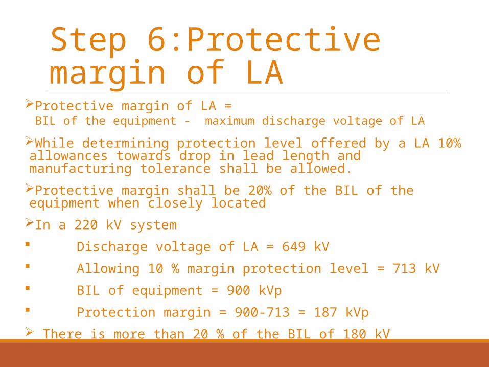
Step 6:Protective margin of LA
Protective margin of LA = BIL of the equipment - maximum discharge voltage of LA
While determining protection level offered by a LA 10% allowances towards drop in lead length and manufacturing tolerance shall be allowed.Protective margin shall be 20% of the BIL of the equipment when closely locatedIn a 220 kV system Discharge voltage of LA = 649 kV Allowing 10 % margin protection level = 713 kV BIL of equipment = 900 kVp Protection margin = 900-713 = 187 kVp There is more than 20 % of the BIL of 180 kV

The L.A. voltage rating
Rated system voltage KV
Highest system voltage KV
Arrester rating in KV
132 145 120/132
220 245 198/216
400 420 336
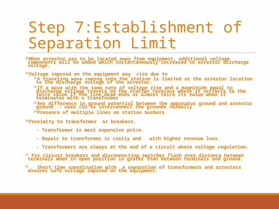
Step 7:Establishment of Separation Limit
When arrestor are to be located away from equipment, additional voltage components will be added which instantaneously increased to arrestor discharge volrage.
Voltage imposed on the equipment may rise due to A traveling wave coming into the station is limited at the arrestor location to the discharge voltage of
the arrestor.If a wave with the same rate of voltage rise and a magnitude equal to discharge voltage travels on the
station terminus where it reflects to the twice value if the line dead ends or almost teice its value when it terminates with a transformer
Any difference in ground potential between the apparatus ground and arrestor ground - uses ≤1Ω to interconnect the grounds normally
Presence of multiple lines on station busbars
Proximity to transformer or breakers.
- Transformer is most expensive price.
- Repair to transformer is costly and with higher revenue loss.
- Transformers are always at the end of a circuit where voltage regulation.
For circuit breakers and disconnecting switches flash over distance between terminals when in open position in grater than between terminals and ground.
. Short time coordination with a separation of transformers and arrestors ensures safe voltage imposed on the equipment.

Location of Lightning Arresters
The electrical circuit length between L.A. and the transformer bushing terminal (inclusive of lead length in metes for effectively earthed) should not exceed the limits given below:
Rated syst. voltage KV
BIL KV Peak
Max. distance
132kV 550
650
35.0
45.0
220kV
400kV
900/1050
1425/1550
Closer to Trans.

Insulation Co-ordination Scheme
For 220 KV system. L.A. Voltage rating=system highest voltage x co-efficient of earthing =245x.8=196Kv.
Selecting standard rating from Table 12.1 column 1,L.A. voltage rating=198 KvDischarge current rating= 10KA (assumed) Residual voltage, from standard table,=649Kv (peak)
Protection level of the L.A. =649x1.1=714KvFor a margin of 20% between the B.I.L. and the protection level of L.A., the B.I.L. should be
=714x1.2=857Kv.Choose BIL from standard Table=900 Kv,The corresponding power freq. I minute test voltage =395kvSwitching surge flashover voltage =220 x6.5=825kv √ 3Check it is less than B.I.L. of 900kv.Power frequency over voltage=220x3=228kv rms
√ 3This is less than 395kv.B.I.L. of CBs, instrument transformer, busbars etc,.=900x1.1=990kv.Choose standard B.I.L for disconnect switches.=1175kv.

Suggest a method :

ReferenceA Text Book on Power System Engineering by M L Soni, A Chakrabarti, P V Gupta and U S Bhatnagar
Substation equipment & operation by Satnam & P V Gupta