Intro to Arduino - Tafila Technical...
50
Intro to Arduino Lecture 6 Interfacing Digital and Analog Devices to Arduino.
Transcript of Intro to Arduino - Tafila Technical...

Intro to Arduino
Lecture 6
Interfacing Digital and Analog Devices to Arduino.

PWR IN
USB
(to Computer)
Analog
INPUTS
Digital I\OPWM(3, 5, 6, 9, 10, 11)
SCL\SDA(I2C Bus)
POWER 5V / 3.3V / GND
RESET

Components
Push Button Digital Input Switch - Closes or opens circuit
Polarized, needs resistor
Trim potentiometer
Analog Input Variable resistor Also called a Trimpot.
Photoresistor Analog Input Light Dependent Resistor (LDR)
Resistance varies with light.
Relay Digital Output Switch driven by a small signal
Used to control larger voltages
Temp Sensor Analog Input Temp Dependent Resistor
Flex Sensor Analog Input Variable resistor
Soft Trimpot Analog Input Variable resistor Careful of shorts
RGB LED Dig & Analog Output
16,777,216 different colors
Ooh... So pretty.
Name Image Type Function Notes
3

Components
4

INPUT vs. OUTPUT
Inputs is a signal / information
going into the board.
Output is any signal exiting the
board.
Examples: Buttons
Switches, Light Sensors,
Flex Sensors, Humidity
Sensors, Temperature
Sensors…
5
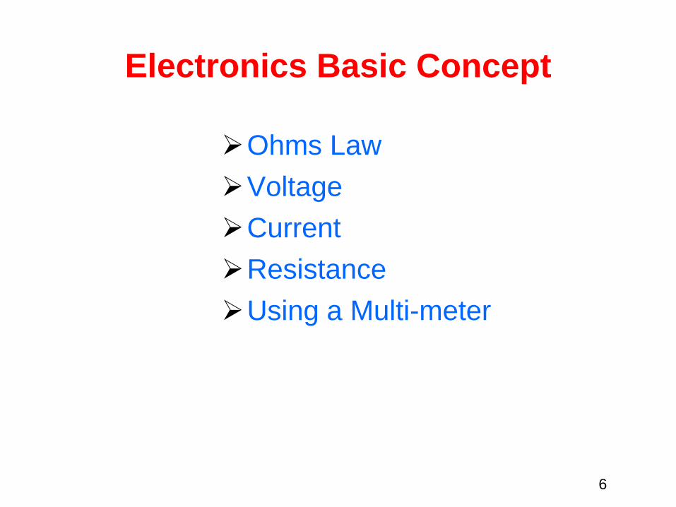
Electronics Basic Concept
Ohms Law
Voltage
Current
Resistance
Using a Multi-meter
6
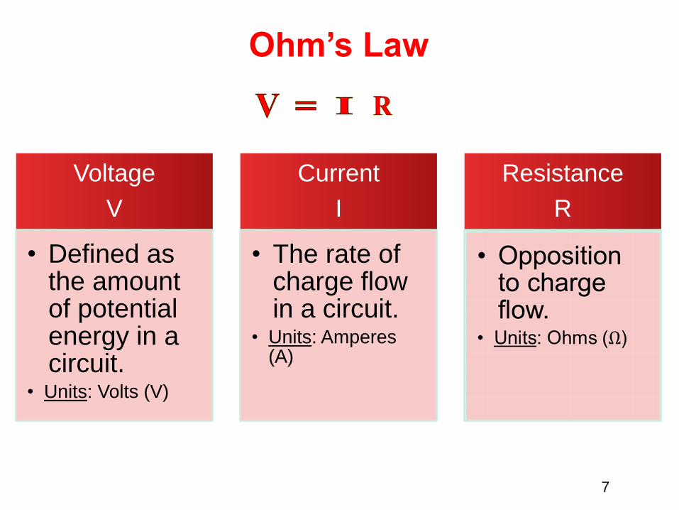
Ohm’s Law
Voltage
V
• Defined as the amount of potential energy in a circuit.
• Units: Volts (V)
Current
I
• The rate of charge flow in a circuit.
• Units: Amperes (A)
Resistance
R
7

Current Flow Analogy
High Current Low Current
8

Water
Tower
Voltage Analogy
More Energy == Higher Voltage Less Energy == Lower Voltage
V
Water
Tower
V
9

Resistance Analogy
Big Pipe == Lower Resistance Small Pipe == Higher Resistance
Water
Tower
Water
Tower
V
10

Continuity –Circuit?
An Electrical Circuit must have a continuous LOOP
from Power (Vcc) to Ground (GND).
Continuity is important to make portions of circuits
are connect. Continuity is the simplest and possibly
the most important setting on your multi-meter.
Sometimes we call this “ringing out” a circuit.
11

Measuring Electricity – Voltage
Voltage is a measure of potential electrical
energy. A voltage is also called a potential
difference – it is measured between two
points in a circuit – across a device.
12

Measuring Electricity -- Current
Current is the measure of the rate of charge flow. For
Electrical Engineers – we consider this to be the
movement of electrons.
In order to measure this – you must break the circuit or
insert the meter in-line (series).
13

Measuring Electricity -- Resistance
Resistance is the measure of how much opposition to
current flow is in a circuit.
Components should be removed entirely from the
circuit to measure resistance. Note the settings on
the multi-meter. Make sure that you are set for the
appropriate range.
Resistance
settings
14

Analog Input
Arduino uses a 10-bit A/D Converter:
• this means that you get input values from 0 to 1023
• 0 V 0
• 5 V 1023
Ex:
int sensorValue = analogRead(A0);
15

Analog InputVoltage Based Sensors
3 Pin Potentiometer(var. resistor)
Voltage Divider Circuit
16
10k

Analog Input
2 Pin Analog Sensors ( var. resistor)
Take two sensors -- Use
the Serial Monitor and find
the range of input values
you get for each sensor.
MaxAnalogRead = _________
MinAnalogRead = _________
17

Reading analog inputs and scaling
const int potPin = 0; // select the input pin for the potentiometer
void loop()
{
int val; // The value coming from the sensor
int percent; // The mapped value
val = analogRead(potPin); // read the voltage on the pot (val 0 to 1023)
percent = map(val,0,1023,0,100); // percent will range from 0 to 100.
}
18
map(value, fromLow, fromHigh, toLow, toHigh)

Analog InputMeasuring Temperature
const int inPin = 0; // analog pin
void loop()
{
int value = analogRead(inPin);
float millivolts = (value / 1024.0) * 3300; //3.3V analog input
float celsius = millivolts / 10; // sensor output is 10mV per //degree Celsius
delay(1000); // wait for one second
}
19

Analog OutputAnalog vs. Digital
To create an analog signal, the microcontroller
uses a technique called PWM. By varying the
duty cycle, we can mimic an “average” analog
voltage.
Pulse Width Modulation (PWM)
20

analogWrite(pin, val);
Pin: refers to the OUTPUT pin
(limited to pins 3, 5, 6, 9, 10, 11.)
– denoted by a ~ symbol
Val (Duty Cycle): (0 – 255).
Analog Output
Fading
21

Fading in and Fading Out LED
int ledPin = 9; // LED connected to digital pin 9
void setup() {
}
void loop()
{
for(int fadeValue = 0 ; fadeValue <= 255; fadeValue +=5)
{
analogWrite(ledPin, fadeValue); // sets the value (range from 0 to 255):
delay(30);
}
for(int fadeValue = 255 ; fadeValue >= 0; fadeValue -=5)
{
analogWrite(ledPin, fadeValue); // sets the value (range from 0 to 255):
delay(30);
}
} 22

Analog OutputColor Mixing/Tri-color LED
this is a standard – Common
Cathode LED
This means the negative side of
the LED is all tied to Ground.
R G B
23

Analog OutputRGB LED
Note: The longest
leg of the RGB
LED is the
Common
Cathode. This
goes to GND.
Use pins 5, 6, & 9
24

Using RGB LED
int redPin = 5;
int greenPin = 6;
int bluePin = 9;
void setup()
{
pinMode(redPin, OUTPUT);
pinMode(greenPin, OUTPUT);
pinMode(bluePin, OUTPUT);
}
25

RGB LED Color Mixing
void loop()
{
analogWrite(redPin, 255);
analogWrite (greenPin, 255);
analogWrite (bluePin, 255);
}
26

Digital Input
Digital Sensors (Switches)
Pull-up Resistor
to Digital Pin 2
27
Signal is always either HIGH (On) 5v or LOW (Off) 0v.
In Arduino, open up:
File Examples 02.Digital Button

Add LED to Pin 13
28

int buttonPin = 2; // the number of the pushbutton pin
int ledPin = 13; // the number of the LED pin
int buttonState = 0; // variable for reading the pushbutton status
void setup() {
pinMode(ledPin, OUTPUT); // initialize the LED pin as an output:
pinMode(buttonPin, INPUT); // initialize the pushbutton pin as an input:
}
void loop()
{
buttonState = digitalRead(buttonPin); // read the state of the pushbutton value:
if (buttonState == HIGH) // check if the pushbutton is pressed.
{
digitalWrite(ledPin, HIGH); // turn LED on:
}
else
{
digitalWrite(ledPin, LOW); // turn LED off:
}
}
Button & LED
29

The problem with the last program is that the
switch has to remain pressed in order for the
LED to turn on.
We want the LED to change state when we
press the button and to stay in the new state
when the button is released
Button & LED
30

int buttonPin = 2; // the pin that the pushbutton is attached to
int ledPin = 13; // the pin that the LED is attached to
int buttonState = 0; // current state of the button
int lastLEDState = 0; // previous state of the button
void setup() {
pinMode(buttonPin, INPUT); // initialize the button pin as a input:
pinMode(ledPin, OUTPUT); // initialize the LED as an output:
}
void loop() {
buttonState = digitalRead(buttonPin); // read the pushbutton input pin:
if (buttonState == HIGH) { // Determine if button State is HIGH
if (lastLEDState == HIGH) { // if the current state is HIGH then turn LED off
digitalWrite(ledPin, LOW);
lastLEDState = LOW;
}
else { // if the current state is LOW then turn LED on
digitalWrite(ledPin, HIGH);
lastLEDState = HIGH;
}
while(buttonState == HIGH){
buttonState = digitalRead(buttonPin); // read the pushbutton input pin:
};
delay(250);
}
}
Button & LED
31

Digital Input
PIR motion sensors
32
A passive infrared sensor (PIR sensor) is an electronic
sensor that measures infrared (IR) light radiating from
objects in its field of view.

Using PIR motion sensors
const int ledPin = 7; // pin for the LED
const int inputPin = 2; // input pin (for the PIR sensor)
void setup() {
pinMode(ledPin, OUTPUT); // declare LED as output
pinMode(inputPin, INPUT); // declare pushbutton as input
}
void loop(){
int val = digitalRead(inputPin); // read input value
if (val == HIGH) // check if the input is HIGH
{
digitalWrite(ledPin, HIGH); // turn LED on if motion detected
delay(500);
digitalWrite(ledPin, LOW); // turn LED off
}
} 33

Digital Output
LED
Move the green
wire to pin 13 (or
any other Digital
I/O pin on the
Arduino board.
34
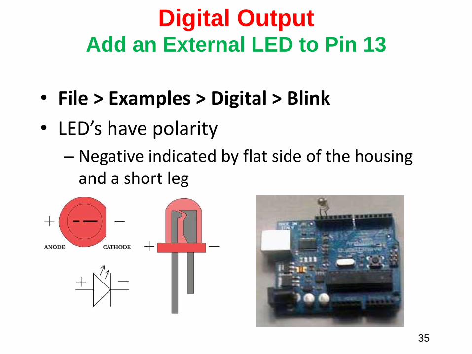
Digital OutputAdd an External LED to Pin 13
• File > Examples > Digital > Blink
• LED’s have polarity
– Negative indicated by flat side of the housing and a short leg
35

int ledPin = 13; // LED connected to digital pin 13
// The setup() method runs once, when the sketch starts
void setup() {
// initialize the digital pin as an output:
pinMode(ledPin, OUTPUT);
}
// the loop() method runs over and over again,
// as long as the Arduino has power
void loop()
{
digitalWrite(ledPin, HIGH); // set the LED on
delay(1000); // wait for a second
digitalWrite(ledPin, LOW); // set the LED off
delay(1000); // wait for a second
}
Using the LED
36

Digital Output/Digital Input
Ultrasonic Sensor
37
Active ultrasonic sensors generate high frequency sound
waves and evaluate the echo which is received back by the
sensor, measuring the time interval between sending the
signal and receiving the echo to determine the distance to an
object.
It has four wires:
1.Vcc------- connect to 5V dc
2.Trigger----pulse input that triggers the sensor
3.Echo----- indicates the reception of echo from the target
4.Gnd------- Ground
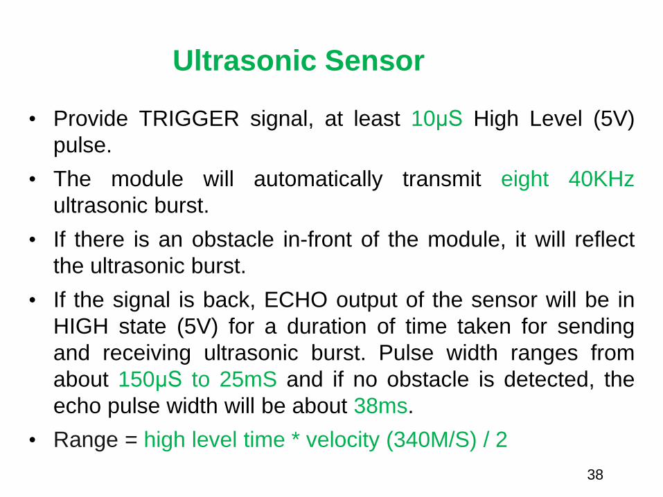
Ultrasonic Sensor
• Provide TRIGGER signal, at least 10μS High Level (5V)
pulse.
• The module will automatically transmit eight 40KHz
ultrasonic burst.
• If there is an obstacle in-front of the module, it will reflect
the ultrasonic burst.
• If the signal is back, ECHO output of the sensor will be in
HIGH state (5V) for a duration of time taken for sending
and receiving ultrasonic burst. Pulse width ranges from
about 150μS to 25mS and if no obstacle is detected, the
echo pulse width will be about 38ms.
• Range = high level time * velocity (340M/S) / 2
38

Timing Diagram
39

Using ultrasonic sensors#include <NewPing.h>
#define TRIGGER_PIN 12 // Arduino pin tied to trigger pin on the ultrasonic sensor.
#define ECHO_PIN 11 // Arduino pin tied to echo pin on the ultrasonic sensor.
#define MAX_DISTANCE 200 // Maximum distance we want to ping for (in centimeters). //Maximum sensor distance is rated at 400-500cm.
NewPing sonar(TRIGGER_PIN, ECHO_PIN, MAX_DISTANCE); // NewPing setup of pins //and maximum //distance.
void setup() {
Serial.begin(115200); // Open serial monitor at 115200 baud to see ping results.
}
void loop() {
delay(50);
unsigned int uS = sonar.ping(); // Send ping, get ping time in microseconds (uS).
Serial.print("Ping: ");
Serial.print(uS / US_ROUNDTRIP_CM); // Convert ping time to distance and print result //(0 = outside set distance range, no ping echo)
Serial.println("cm");
}
40

Digital Output
Sound-Piezo
A Piezo is an electronic piece that converts electricity
energy to sound. It is a digital output device. You can
make white noise or even exact musical notes (
frequencies for musical notes) based on the duration
that you iterate between HIGH and LOW signals.
A Piezo is a directional piece, meaning that it has a
positive and negative pole. The positive pole should
be connected to the digital output pin that you allocate
to control the piezo and the negative pole should be
connected to Ground pin 41

Digital Output
Piezo
//connect piezo to pin 13 and ground
int freqs[] = {
1915, 1700, 1519, 1432, 1275, 1136, 1014, 956};
//string tones[] = {"do", "re", "mi", "fa","sol"," la", "si", "do"};
void setup(){
pinMode(13,OUTPUT);
}
void loop(){
for(int i=0;i<8;i++){//iterating through notes
for(int j=0;j<1000;j++){//the time span that each note is being played
digitalWrite(13,HIGH);
delayMicroseconds(freqs[i]);
digitalWrite(13,LOW);
delayMicroseconds(freqs[i]);
}
}
} 42

DigitalOutput
1. Servo Motor
Servo Motors are electronic devices that convert digital
signal to rotational movement.
It has three connections: the black is ground, the red is
connected to 5V, and the white (yellow wire) is set to the
digital pin.43

DigitalOutput
Using Servo Motor
44
#include <Servo.h>
Servo myservo; // create servo object to control a servo
int pos = 0; // variable to store the servo position
void setup()
{
myservo.attach(9); // attaches the servo on pin 9 to the servo object
}
void loop()
{
for(pos = 0; pos <= 180; pos += 1) // goes from 0 degrees to 180 degrees in steps of 1 degree
{
myservo.write(pos); // tell servo to go to position in variable 'pos'
delay(15); // waits 15ms for the servo to reach the position
}
for(pos = 180; pos>=0; pos-=1) // goes from 180 degrees to 0 degrees
{
myservo.write(pos); // tell servo to go to position in variable 'pos'
delay(15); // waits 15ms for the servo to reach the posit ion
}
}

Digital Output
2. DC Motor// Connect to Pin 13 and Ground
void setup(){
pinMode(13, OUTPUT); // Specify Arduino Pin number
and output/input mode
}
void loop(){
digitalWrite(13, HIGH); // Turn on Pin 13 sending a
HIGH Signal
delay(1000); // Wait for one second
digitalWrite(13, LOW); // Turn off Pin 13 sending a
LOW Signal
delay(3000); // Wait for Three second
}
45
// Connect to Pin 13 and 12
void setup(){
pinMode(13, OUTPUT); // Specify Arduino Pin number
and output/input mode
pinMode(12, OUTPUT);
}
void loop(){
digitalWrite(13, HIGH); // Turn on Pin 13 sending a
HIGH Signal
digitalWrite(12, LOW); //Make Pin 12 a Ground
delay(1000); // Wait for one second
digitalWrite(13, LOW); // Make Pin 13 a Ground
digitalWrite(12, HIGH); // Turn on Pin 12 sending a
HIGH Signal
delay(3000); // Wait for Three second
}
Code for Rotation/No Rotation
Code for CW and CCW Rotation

Stepper motors translate digital switching sequences into motion. They are used
in a variety of applications requiring precise motions under computer control.
Unlike ordinary dc motors, which spin freely when power is applied, steppers
require that their power source be continuously pulsed in specific patterns. These
patterns, or step sequences, determine the speed and direction of a stepper’s
motion.
For each pulse or step input, the stepper motor rotates a fixed angular increment;
typically 1.8 or 7.5 degrees.
Digital Output
3. Stepper Motor
46

The most common stepper is the four-coil unipolar variety. These are
called unipolar because they require only that their coils be driven on
and off. Bipolar steppers require that the polarity of power to the coils
be reversed.
The normal stepping sequence for four-coil unipolar steppers appears
in the figure. If you run the stepping sequence in the figure forward, the
stepper rotates clockwise; run it backward, and the stepper rotates
counterclockwise.
The motor’s speed depends on how fast the controller (L293D,
ULN2003/2004) runs through the step sequence. At any time the
controller can stop in mid sequence.
Stepper Motor
47

void setup(){pinMode(2,OUTPUT);pinMode(3,OUTPUT);pinMode(4,OUTPUT);pinMode(5,OUTPUT);
}void loop(){// Pause between the types that determines the speedint stepperSpeed=200;// Change to change speedint dir=1;// change to -1 to change directionif (dir==1){ //Running ClockwisedigitalWrite(2,HIGH);//Step 1digitalWrite(3,LOW);digitalWrite(4,HIGH);digitalWrite(5,LOW);delay(stepperSpeed);// Pause between the types that determines the speeddigitalWrite(2,HIGH);//Step 2digitalWrite(3,LOW);digitalWrite(4,LOW);digitalWrite(5,HIGH);delay(stepperSpeed);// Pause between the types that determines the speeddigitalWrite(2,LOW);//Step 3digitalWrite(3,HIGH);digitalWrite(4,LOW);digitalWrite(5,HIGH);delay(stepperSpeed);// Pause between the types that determines the speeddigitalWrite(2,LOW);//Step 4digitalWrite(3,HIGH);digitalWrite(4,HIGH);digitalWrite(5,LOW);delay(stepperSpeed);// Pause between the types that determines the speed}if (dir==-1){ //Running CounterClockwisedigitalWrite(2,LOW);//Step 4digitalWrite(3,HIGH);digitalWrite(4,HIGH);digitalWrite(5,LOW);delay(stepperSpeed);// Pause between the types that determines the speeddigitalWrite(2,LOW);//Step 3digitalWrite(3,HIGH);digitalWrite(4,LOW);digitalWrite(5,HIGH);delay(stepperSpeed);// Pause between the types that determines the speeddigitalWrite(2,HIGH);//Step 2digitalWrite(3,LOW);digitalWrite(4,LOW);digitalWrite(5,HIGH);delay(stepperSpeed);// Pause between the types that determines the speeddigitalWrite(2,HIGH);//Step1digitalWrite(3,LOW);digitalWrite(4,HIGH);digitalWrite(5,LOW);delay(stepperSpeed);// Pause between the types that determines the speed}
}
Stepper Moto
Direction and Speed
48

Driving Motors or other High Current
Loads
NPN Transistor (Common Emitter “Amplifier” Circuit)
to Digital
Pin 9
49

Digital Output – Controling any Electrical Device
with any power needs using a relay
// Connect to Pin 13 and Ground
void setup(){
pinMode(13, OUTPUT); // Specify Arduino Pin number and
output/input mode
}
void loop(){
digitalWrite(13, HIGH); // Turn on Pin 13 sending a HIGH Signal
delay(1000); // Wait for one second
digitalWrite(13, LOW); // Turn off Pin 13 sending a LOW Signal
delay(3000); // Wait for Three second
}
Externally Powered Device
Externally Powered Device
Exte
rnal P
ow
er
3v-2
20v
Control Pin50