
Temp Shock
13
MIL-STD-810G METHOD 503.5 METHOD 503.5 TEMPERATURE SHOCK NOTE: Tailoring is essential. Select methods, procedures, and parameter levels based on the tailoring process described in Part One, paragraph 4.2.2, and Annex C. Apply the general guidelines for laboratory test methods described in Part One, paragraph 5 of this standard. 1. SCOPE. 1.1 Purpose. Use the temperature shock test to determine if materiel can withstand sudden changes in the temperature of the surrounding atmosphere without experiencing physical damage or deterioration in performance. For the purpose of this document, "sudden changes" is defined as "an air temperature change greater than 10°C (18°F) within one minute." 1.2 Application. 1.2.1 Normal environment. Use this method when the requirements documents specify the materiel is likely to be deployed where it may experience sudden changes of air temperature. This method is intended to evaluate the effects of sudden temperature changes of the outer surfaces of materiel, items mounted on the outer surfaces, or internal items situated near the external surfaces. This method is, essentially, surface-level tests. Typically, this addresses: a. The transfer of materiel between climate-controlled environment areas and extreme external ambient conditions or vice versa, e.g., between an air conditioned enclosure and desert high temperatures, or from a heated enclosure in the cold regions to outside cold temperatures. b. Ascent from a high temperature ground environment to high altitude via a high performance vehicle (hot to cold only). c. Air delivery/air drop at high altitude/low temperature from aircraft enclosures when only the external material (packaging or materiel surface) is to be tested. 1.2.2 Safety and screening. Except as noted in paragraph 1.3, use this method to reveal safety problems and potential flaws in materiel normally exposed to less extreme rates of temperature change (as long as the test conditions do not exceed the design limitations of the materiel). 1.3 Limitations. This method does not specifically address the following, but it may, in some cases, be applied through tailoring: a. Materiel that will not experience sudden extreme temperature changes to internal components because of its mass, configuration, packaging, installed location, etc. b. Replacement of the assessment of performance characteristics after lengthy exposure to extreme temperatures, such as with Methods 501.5 and 502.5. c. Temperature shock experienced by materiel transferred between air and liquid or two liquids, the thermal shock caused by rapid transient warmup by engine compressor bleed air, or aerodynamic loading. d. This method is inappropriate if the actual transfer time in a service environment will not produce a significant thermal shock. e. Materiel that has been exposed to heat from a fire and subsequently cooled with water. f. Thermal shock testing that may be considered for safety or hazard assessment of munitions, but that should be accomplished in accordance with MIL-STD-2105C (reference 6.1c). 503.5-1
-
Upload
stefano-barbieri -
Category
Documents
-
view
35 -
download
0
description
temperature shock test norm MIL-STD-810G
Transcript of Temp Shock

MIL-STD-810G METHOD 503.5
METHOD 503.5
TEMPERATURE SHOCK
NOTE: Tailoring is essential. Select methods, procedures, and parameter levels based on the tailoring process described in Part One, paragraph 4.2.2, and Annex C. Apply the general guidelines for laboratory test methods described in Part One, paragraph 5 of this standard.
1. SCOPE.
1.1 Purpose. Use the temperature shock test to determine if materiel can withstand sudden changes in the temperature of the surrounding atmosphere without experiencing physical damage or deterioration in performance. For the purpose of this document, "sudden changes" is defined as "an air temperature change greater than 10°C (18°F) within one minute."
1.2 Application.
1.2.1 Normal environment. Use this method when the requirements documents specify the materiel is likely to be deployed where it may experience sudden changes of air temperature. This method is intended to evaluate the effects of sudden temperature changes of the outer surfaces of materiel, items mounted on the outer surfaces, or internal items situated near the external surfaces. This method is, essentially, surface-level tests. Typically, this addresses:
a. The transfer of materiel between climate-controlled environment areas and extreme external ambient conditions or vice versa, e.g., between an air conditioned enclosure and desert high temperatures, or from a heated enclosure in the cold regions to outside cold temperatures.
b. Ascent from a high temperature ground environment to high altitude via a high performance vehicle (hot to cold only).
c. Air delivery/air drop at high altitude/low temperature from aircraft enclosures when only the external material (packaging or materiel surface) is to be tested.
1.2.2 Safety and screening. Except as noted in paragraph 1.3, use this method to reveal safety problems and potential flaws in materiel normally exposed to less extreme rates of temperature change (as long as the test conditions do not exceed the design limitations of the materiel).
1.3 Limitations. This method does not specifically address the following, but it may, in some cases, be applied through tailoring:
a. Materiel that will not experience sudden extreme temperature changes to internal components because of its mass, configuration, packaging, installed location, etc.
b. Replacement of the assessment of performance characteristics after lengthy exposure to extreme temperatures, such as with Methods 501.5 and 502.5.
c. Temperature shock experienced by materiel transferred between air and liquid or two liquids, the thermal shock caused by rapid transient warmup by engine compressor bleed air, or aerodynamic loading.
d. This method is inappropriate if the actual transfer time in a service environment will not produce a significant thermal shock.
e. Materiel that has been exposed to heat from a fire and subsequently cooled with water. f. Thermal shock testing that may be considered for safety or hazard assessment of munitions, but that should
be accomplished in accordance with MIL-STD-2105C (reference 6.1c).
503.5-1

MIL-STD-810G METHOD 503.5
2. TAILORING GUIDANCE.
2.1 Selecting this Method. After examining requirements documents and applying the tailoring process in Part One of this standard to determine where thermal shocks are foreseen in the life cycle of the materiel, use the following to confirm the need for this method and to place it in sequence with other methods.
2.1.1 Effects of thermal shock environments. Effects of thermal shocks are usually more severe near the outer portions of materiel. The further from the surface (depending, of course, on the properties of the material involved), the slower and less significant are the thermal changes. Transit cases, packaging, etc., will lessen the effects of thermal shock on the enclosed materiel even more. Sudden temperature changes may either temporarily or permanently affect operation of materiel. The following are examples of problems that could result from thermal shock exposure that may relate to the materiel being tested. Consider the following typical problems to help determine if this method is appropriate for the materiel being tested. This list is not intended to be all-inclusive.
a. Physical. (1) Shattering of glass vials and optical materiel. (2) Binding or slackening of moving parts. (3) Cracking of solid pellets or grains in explosives. (4) Differential contraction or expansion rates or induced strain rates of dissimilar materials. (5) Deformation or fracture of components. (6) Cracking of surface coatings. (7) Leaking of sealed compartments. (8) Failure of insulation protection.
b. Chemical. (1) Separation of constituents. (2) Failure of chemical agent protection.
c. Electrical. (1) Changes in electrical and electronic components. (2) Electronic or mechanical failures due to rapid water or frost formation. (3) Excessive static electricity.
2.1.2 Sequence among other methods. a. General. See Part One, paragraph 5.5. b. Unique to this method. Use test item response characteristics and performance determination
information obtained from the high and low temperature tests to better define the test conditions to be used for this procedure.
2.2 Selecting Procedure Variations. This method includes one test procedure with four variations – essentially in the length of the test and the shock itself. It employs constant temperature at each of the extreme shock conditions because, in many instances, the thermal shock itself so outweighs the other thermal effects that the test may be performed using two constant temperatures. This is particularly the case when more severe shocks are desired, such as for evaluation of safety or initial design, and when extreme values will be used. Below are possible considerations and variations.
2.2.1 Procedure selection considerations. When selecting this procedure, consider:
a. The expected exposure temperatures in service. b. The materiel's logistic or deployment configuration.
503.5-2

MIL-STD-810G METHOD 503.5
2.2.2 Procedure variations. The four procedure variations all involve temperature conditioning and performance testing. They differ on the number of shocks that, based on the LCEP, can vary from one shock (1/2 cycle) to six or more shocks (three or more cycles. Paragraph 2.3 includes five possible options, but only use 2.3c and d for cyclic situations.
2.3 Determine Test Levels and Conditions. Having selected this method (based on the test item's requirements documents and the tailoring process), complete the tailoring process by identifying appropriate parameter levels and applicable test conditions and techniques for the procedure. Base these selections on the requirements documents, the Life Cycle Environmental Profile (LCEP), requirements documents (see Part One, Figure 1-1), and information provided with this method. Consider tailoring known service extreme temperatures if the intent of the test is to reproduce induced strain rates found in service. Use values other than those suggested if realistic. This method addresses several exposure situations: aircraft flight exposure, air delivery - desert, and ground transfer – ambient to either cold regions or desert. Based on the anticipated deployment, determine which test variation is applicable. Rather than focusing solely on shocks from low to high temperatures or vice-versa, exposure temperatures could reflect shocks from standard ambient conditions to high or low temperatures. Base the exposure range on the expected service conditions, but extend the test levels as necessary to detect design flaws. Stabilize the whole test item temperature or, if known, the point of interest prior to transfer. However, if the LCEP indicates a duration less than that required to achieve stabilization then the duration from the LCEP should be used. The critical point of interest may be near the surface of the item. In such cases, a considerably shorter duration may apply rather than complete stabilization of the item. Any duration less than complete stabilization shall be justified. Consider the following when selecting test levels.
a. Aircraft flight exposure. This is appropriate if the materiel is to be exposed to desert or tropical ground heat and possible direct solar heating and, immediately afterwards, exposed to the extreme low temperatures associated with high altitude (see paragraph 1.2.1b). If not expended, the test item could subsequently be exposed to a potential thermal shock when the platform aircraft returns to a hot ambient environment. In addition, if not expended, the item could also be subjected to multiple thermal shocks.
b. Air delivery - desert. This is appropriate for materiel that is delivered over desert terrain from unheated, high-altitude aircraft, but use the ambient air temperature (no solar loading).
c. Ground transfer - ambient to or from either cold regions or desert. This is intended to test materiel for the effects of movement to and from ambient conditions and cold regions or desert environments.
d. Engineering design. This is used to detect issues related to marginal design.
2.3.1 Climatic conditions. Identify the appropriate climatic conditions for the geographic areas in which the materiel will be operated and stored. Actual response temperatures achieved when materiel is exposed to the climatic conditions of the various ground climatic categories could be obtained from the test results of high and low temperature exposure (methods 501.5, 502.5, and 505.5) for either the operational, or storage configuration. The latter assumption must take into account the induced effects of solar radiation during storage and transit in various climates.
2.3.2 Exposure conditions. Select the test temperatures from field data or from the requirements documents, if available. If not available, determine the test temperatures from the anticipated deployment application or world areas in which the materiel will be deployed, or from the most extreme non-operating temperature requirements. Recommend using a range of temperatures that reflects that anticipated in-service, rather than some arbitrary extreme range.
a. Deployment application (aircraft flight exposure). The thermal stresses and rates that materiel will experience during exposure to the air flight operational environment are dependent on the ambient conditions, flight conditions, and performance of the onboard environmental control systems. The temperature and humidity at various altitudes can be found in MIL-HDBK-310 (paragraph 6.1, reference a).
503.5-3

MIL-STD-810G METHOD 503.5
b. Air delivery/air drop. The test conditions for this exposure are based upon the probable conditions in the
cargo compartment of the aircraft (or other transport location), and on the ground at the point of impact. Use a lower temperature extreme that assumes an unheated, unpressurized aircraft cargo compartment with the aircraft at an altitude of 8 kilometers (26,200 ft). This is the limiting altitude for cargo aircraft because of oxygen-pressure requirements when the aircraft cargo compartment is unpressurized immediately before air drop operations. The temperature at this altitude can be found in MIL-HDBK-310. Determine the high temperature surface extremes from the appropriate tables in Method 501.5.
NOTE: Materiel packaging will normally mitigate thermal shocks to the packaged item. The air delivery/air drop scenario of packaged items may not involve significant thermal shock to the contents. However, the packaging may experience adverse effects due to the thermal shock.
c. Ground transfer – ambient to or from cold regions or desert.
In some regions of the world, materiel could experience thermal shocks during movement to and from environmentally conditioned buildings (enclosures) to extreme exterior ambient temperature conditions. Base selection of the outside ambient conditions upon the climatic categories or areas listed in the appropriate table in Method 501.5 or 502.5.
(1) Cold regions. Typically, conditions for cold regions enclosures are indoor air at 18°C to 24°C (65°F to 75°F), with an accompanying RH of 30 to 50% (reference 6.1d). These conditions roughly correspond to normal heating practices in cold regions.
(2) Desert. For transfer from a desert environment to an air conditioned enclosure, determine if solar heating of the materiel will occur prior to the transfer.
d. Engineering design. Use test conditions that reflect the extreme anticipated storage conditions.
2.3.3 Test duration (number of shocks). a. Procedure I-A One-way shock(s) from constant extreme temperature. For materiel that is likely to be
exposed only rarely to thermal shock in one direction, perform at least one shock for each appropriate condition, i.e., low to high temperature, or vice-versa (Figure 503.5-1 and 4.4.2.1a).
b. Procedure I-B Single cycle shock from constant extreme temperature. For materiel that is likely to be exposed to only one thermal shock cycle (one in each direction), perform one shock for each appropriate condition, i.e., low-to-high temperature, and one in the opposite direction (Figure 503.5-2 and 4.4.2.1b).
c. Procedure I-C Multi-cycle shocks from constant extreme temperature. There is little available data to substantiate a specific number of shocks when more frequent exposure is expected. In lieu of better information, apply a minimum of three shocks at each condition, i.e., three transfers from cold to hot, three transfers from hot to cold, and a stabilization period after each transfer. The number of shocks depends primarily on the anticipated service events (Figure 503.5-3 and 4.4.2.1c). The objective of this test is to determine the effect of rapid temperature changes to the materiel. Therefore, expose the test item to the temperature extremes for a duration equal to either the actual operation, or to that required to achieve temperature stabilization within the limitations shown in paragraphs 1.2.1, 1.3, 2.1.1, and 2.3.5.
d. Procedure I-D Shocks to or from controlled ambient temperature. This procedure essentially follows the durations of Procedures I-A to I-C, except all shocks are to and/or from controlled ambient conditions (Figure 503.5-4 and 4.4.2.1d).
2.3.4 Test item configuration. The configuration of the test item strongly affects test results. Therefore, use the anticipated configuration of the item during storage, shipment, or use. For small test items (e.g., radios), the test configuration should be representative of the in-Service condition, and provide a similar mounting platform thermal mass. As a minimum, consider the following configurations:
a. In a shipping/storage container or transit case, and installation of a thermally conditioned item into a container conditioned at another temperature.
b. Protected or unprotected. c. Deployed (realistically or with restraints).
503.5-4

MIL-STD-810G METHOD 503.5
d. Modified with kits for special applications. e. Packaged for airdrop. f. The installed environment and the effect upon the test item thermal response.
2.3.5 Temperature stabilization. Stabilize the test item temperature (prior to transfer, and within the limitations shown in paragraphs 1.2.1, 1.3, and 2.1.1) for as long as necessary to ensure a uniform temperature throughout at least the outer portions of the test item.
2.3.6 Relative humidity. For most test programs, the relative humidity (RH) is not controlled. During the thermal shock test it may, however, have a significant effect on some materiel, e.g., cellulosic materials that are typically porous, into which moisture can migrate and then expand upon freezing. Do not attempt to control relative humidity unless specifically required.
2.3.7 Transfer time. Ensure the transfer time reflects the time associated with the actual thermal shock in the life cycle profile. Make the transfer as rapidly as possible, but if the transfer takes more than one minute, justify the extra time.
2.4 Special Considerations. The test conditions as presented in this method are intended to be in general agreement with other extremes described in this document. The primary purpose in establishing these levels is to provide realistic conditions for the traverse between the two temperature extremes. Therefore, before transfer, stabilize the test item (within the limitations shown in paragraphs 1.2.1, 1.3, 2.1.1, and 2.3.5) at the most realistic temperature that would be encountered during the specific operation, or possibly the most extreme test item stabilization temperature if appropriate. Consider tailoring known service extreme temperatures if the intent of the test is to reproduce induced strain or heat transfer rates found in service.
3. INFORMATION REQUIRED.
3.1 Pretest. The following information is required to conduct temperature shock tests adequately.
a. General. Information listed in Part One, paragraphs 5.7 and 5.9, and Annex A, Task 405 of this standard.
b. Specific to this method. (1) Test item configuration. (2) Test temperature extremes or test item thermal rates of change. (3) Duration of exposure at each temperature. (4) Test item response temperature (from either Method 501.5 or 505.5). (5) The component/assembly/structure to be used for thermal response and temperature stabilization
purposes (if required). (See Part One, paragraph 5.4.) (6) The number and type of shocks, i.e., shocks from low temperature to high temperature or vice-versa,
or a combination of these. c. Tailoring. Necessary variations in the basic test procedures to accommodate LCEP requirements and/or
facility limitations.
3.2 During Test. Collect the following information during conduct of the test:
a. General. Information listed in Part One, paragraph 5.10, and in Annex A, Task 406 of this standard. b. Specific to this method.
(1) Record of chamber temperature versus time conditions. (2) Test item temperatures (measured locations). (3) Transfer times (e.g., "door open" to "door closed"). (4) Duration of each exposure.
503.5-5

MIL-STD-810G METHOD 503.5
For test validation purposes, record deviations from planned or pre-test procedures or parameter levels, including any procedural anomalies that may occur.
3.3 Post-test. The following post-test data shall be included in the test report:
a. General. Information listed in Part One, paragraph 5.13, and in Annex A, Tasks 405 and 406 of this standard.
b. Specific to this method. (1) Test temperatures. (2) Duration of each exposure. (3) Number of cycles. (4) Transfer times (e.g., "door open" to "door closed"). (5) Results of operational checks. (6) Status of the test item for each visual examination. (7) Previous test methods, if any, to which the specific test item has been exposed. (8) Any deviations from the original test plan.
4. TEST PROCESS.
4.1 Test Facility.
4.1.1 Apparatus. The required apparatus consists of two chambers or cabinets, or a two-celled chamber in which the test conditions can be established and maintained. Unless otherwise specified, use chambers equipped so that after the transfer of the test item, the test conditions within the chamber can be stabilized within five minutes. Use materiel handling equipment, if necessary, for transfer of the test item between chambers.
4.1.2 Instrumentation. Use chambers equipped with auxiliary instrumentation capable of monitoring (see Part One, paragraph 5.18) the test conditions throughout an envelope of air surrounding the test item(s). (See Part One, paragraphs 5.2a and 5.3.) Quick-disconnect thermocouples may be necessary for monitoring test item conditions following transfers.
4.2 Controls. Record chamber temperature, and if required humidity, at a sufficient rate to capture data necessary for post-test analysis (see Part One, paragraph 5.18).
4.2.1 Temperature. Unless otherwise specified in the test plan, if any action other than test item operation (such as opening of the chamber door, except at transfer time) results in a significant change (more than 2°C (3.6°F)) of the test item temperature or chamber air temperature, stabilize the test item at the required temperature in accordance with paragraph 2.3.5 before continuation.
4.2.2 Air velocity. Unless justified by the materiel's platform environment or logistic scenario, and to provide standard testing conditions, use an air velocity that does not exceed 1.7 m/s (335 ft/min) in the vicinity of the test item. A test tailored to meet a specific air velocity or platform environment may require the specification of the air velocity, temperature change rate, or transfer time.
4.2.3 Transfer time. Transfer the test item between the two environments within one minute. If the item is large and requires materiel handling equipment, justify the additional time required to move the item.
4.3 Test Interruption. Test interruptions can result from two or more situations, one being from malfunction of test chambers or associated test laboratory equipment. The second type of test interruption results from failure or malfunction of the test item itself during performance checks (required or optional).
503.5-6

MIL-STD-810G METHOD 503.5
4.3.1 Interruption due to chamber malfunction.
a. General. See Part One, paragraph 5.11 of this standard. b. Specific to this method.
a. Undertest interruption. If, during the temperature dwell, an unscheduled test interruption occurs that causes the test conditions to exceed allowable tolerances toward standard ambient temperatures, reinitiate the test at the point of interruption and stabilize the test item in accordance with paragraph 2.3.5 at the pre-transfer test condition. If the interruption occurs during the transfer, stabilize the test item at the previous temperature and then transfer.
b. Overtest interruption. Following any interruption that results in more extreme exposure of the test item than that required by the materiel specification, conduct a complete physical examination and operational check of the test item (where possible), before any continuation of testing. This is especially true where a safety problem could exist, such as with munitions. If no problem is discovered, reestablish pre-interruption conditions and continue from the point where the test tolerances were exceeded. If the test item fails to operate or a visual defect is noted: (1) Follow the guidance in paragraph 4.3.2, or (2) Replace / repair the failed or non-functioning component or assembly with one that functions as
intended, reestablish pre-failure test conditions, and continue the test from the point of interruption.
4.3.2 Interruption due to test item operation failure. Failure of the test item(s) to function as required during required or optional performance checks during testing presents a situation with several possible options. See Part One, paragraph 5.11 of this standard. a. The preferable option is to replace the test item with a “new” one and restart from Step 1. b. A second option is to replace / repair the failed or non-functioning component or assembly with one
that functions as intended, and restart the entire test from Step 1. If a failure occurs near the end of a sequential test, consider repairing the test item and then re-starting the temperature shock test from beginning. One must consider that prior testing using the same test item may have induced effects that surface during these or subsequent methods. Repeating the sequential environmental tests previously performed, but with a new test item, must be considered. If this is not done and test item failure occurs during the remainder of the test, the test results could be invalid due to the overtest condition.
NOTE: When evaluating failure interruptions, consider prior testing on the same test item and consequences of such.
4.4 Test Execution. The following steps, alone or in combination, provide the basis for collecting necessary information concerning the materiel's susceptibility to temperature shock.
4.4.1 Preparation for test.
4.4.1.1 Preliminary steps. Before starting the test, review pretest information in the test plan to determine test details (e.g., procedures, test item configuration, temperature levels, cycles, temperature stabilization determination, durations, etc.). (See paragraph 3.1 above.)
4.4.1.2 Pretest standard ambient checkout. All test items require a pretest standard ambient checkout to provide baseline data. Examine munitions (see paragraph 1.3f) and other appropriate materiel by nondestructive examination methods. Conduct the checkout as follows:
Step 1. Conduct a complete visual examination of the test item (evaluate against paragraph 2.1.1) with special attention to stress areas such as corners of molded areas and interfaces between different materials (e.g., component lead/ceramic interfaces of visible electronic parts), and document the results for comparison with post test data.
Step 2. Conduct an operational checkout at standard ambient conditions (Part One, paragraph 5.1), and in accordance with the approved test plan, and record the results.
503.5-7

MIL-STD-810G METHOD 503.5
Step 3. In order to determine thermal response (paragraph 3.1b), install temperature sensors in, on, or
around the test item as described in the test plan. Step 4. If the test item operates satisfactorily, proceed to the next step. If not, resolve the problems and
restart at Step 1, above. Step 5. With the test item in the chamber in its appropriate logistic configuration, adjust the chamber air
temperature to controlled ambient conditions and stabilize the test item prior to proceeding to the appropriate procedure.
4.4.2 Procedure. The following procedure and its variations provide the basis for collecting the necessary information concerning materiel experiencing a severe temperature shock environment. The procedures depicted in figures 503.5-1 through 503.5-4 arbitrarily begin with the lower temperature, but could be reversed to begin with the higher temperature if it is more realistic.
NOTE: Unless the requirements documents indicate otherwise, if either of the following test procedure variations is interrupted because of work schedules, etc., maintaining the test item at the test temperature for the time required will facilitate completion of the test when resumed. If the temperature is changed, before continuing the test, restabilize the test item at the temperature of the last successfully completed period before the interruption. Caution: When soaking at high temperature, e.g., overnight, ensure the total test time at the most severe temperature does not exceed the life expectancy of any material (see Part One, paragraph 5.19).
4.4.2.1 Procedure I - Shock from constant extreme temperatures. (Figures 503.5-1 to -3)
a. Procedure I-A. One-way shock(s) from constant extreme temperature. (Figure 503.5-1) Step 1. With the test item in the chamber in its appropriate logistic configuration, adjust the chamber
air temperature to the high or low temperature extreme specified in the test plan (T1) at a rate not to exceed 3°C/min (5°F/min). Stabilize the temperature for a period as determined in accordance with paragraph 2.3.5.
Step 2. Transfer the test item in no more than one minute to an atmosphere at temperature (T2) that will produce the thermal shock specified in the test plan, and stabilize the temperature for a period as determined in accordance with paragraph 2.3.5. Step 3. If required in the test plan, evaluate the effects of the thermal shock on the test item to the
extent practical. Step 4. If other one-way shocks are required, repeat Steps 1-3. Otherwise, return the test item to
standard ambient conditions at a rate not to exceed 3°C/min (5°F/min). Step 5. Examine the test item and, if appropriate, perform an operational check. Record the results
for comparison with pretest data. If the test item fails to operate as intended, see paragraph 5 for analysis of results.
NOTES: - “Cycle” means one shock in each direction, followed by temperature stabilization periods. - T1 and T2 can be reversed based on the LCEP and application. - Procedures I-A to I-D can be tailored to reflect one or more shocks to and from standard ambient
conditions to hot or cold conditions. (See Procedure I-D and Figure 503.5-4.)
503.5-8
MIL-STD-810G METHOD 503.5
Tem
pera
ture
T2
T1
ControlledAmbient
Ramp Rate <3oC/min
½ Cycle
Transfer Rate 1 minute max.
Note: Shocks can be conducted from controlled a bient mto T1 or T2
Ramp Rate o C/min <3
Time
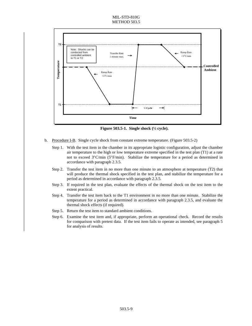
Figure 503.5-1. Single shock (½ cycle).
b. Procedure I-B. Single cycle shock from constant extreme temperature. (Figure 503.5-2)
Step 1. With the test item in the chamber in its appropriate logistic configuration, adjust the chamber air temperature to the high or low temperature extreme specified in the test plan (T1) at a rate not to exceed 3°C/min (5°F/min). Stabilize the temperature for a period as determined in accordance with paragraph 2.3.5.
Step 2. Transfer the test item in no more than one minute to an atmosphere at temperature (T2) that will produce the thermal shock specified in the test plan, and stabilize the temperature for a period as determined in accordance with paragraph 2.3.5.
Step 3. If required in the test plan, evaluate the effects of the thermal shock on the test item to the extent practical.
Step 4. Transfer the test item back to the T1 environment in no more than one minute. Stabilize the temperature for a period as determined in accordance with paragraph 2.3.5, and evaluate the thermal shock effects (if required).
Step 5. Return the test item to standard ambient conditions. Step 6. Examine the test item and, if appropriate, perform an operational check. Record the results
for comparison with pretest data. If the test item fails to operate as intended, see paragraph 5 for analysis of results.
503.5-9

MIL-STD-810G METHOD 503.5
ControlledAmbient
Ramp Rate <3oC/min
Ramp Rate <3 o C/min
1 Cycle
Transfer Rate 1 minute max.
Transfer Rate 1 minute max.
Note: Shocks can be conducted from controlled a bient mto T1 or T2
Time
T2T
empe
ratu
re
T1
Figure 503.5-2. Single cycle shocks.
c. Procedure I-C. Multi-cycle shocks from constant extreme temperature. (Figure 503.5-3) Step 1. With the test item in the chamber in its appropriate logistic configuration, adjust the chamber
air temperature to the high or low temperature extreme specified in the test plan (T1) at a rate not to exceed 3°C/min (5°F/min). Stabilize the temperature for a period as determined in accordance with paragraph 2.3.5.
Step 2. Transfer the test item in no more than one minute to an atmosphere at temperature (T2) that will produce the thermal shock specified in the test plan, and stabilize the temperature for a period as determined in accordance with paragraph 2.3.5.
Step 3. If required in the test plan, evaluate the effects of the thermal shock on the test item to the extent practical.
Step 4. Transfer the test item back to the T1 environment in less than one minute. Stabilize the temperature for a period as determined in accordance with paragraph 2.3.5, and evaluate the thermal shock effects (if required).
Step 5. Repeat steps 2-4 at least twice for a minimum of three cycles. Step 6. Return the test item to standard ambient conditions. Step 7. Examine the test item and, if appropriate, perform an operational check. Record the results
for comparison with pretest data. If the test item fails to operate as intended, see paragraph 5 for failure analysis and follow the guidance in paragraph 4.3.2 for test item failure.
503.5-10

MIL-STD-810G METHOD 503.5
Tem
pera
ture
ControlledAmbient
Ramp Rate <3oC/min
Ramp Rate <3 o C/min
1 Cycle
Transfer Rate 1 minute max.
Note: Shocks can be conducted from controlled ambient to T1 or T2
Time
T2
T1
Figure 503.5-3. Multi-cycle shocks.
d. Procedure I-D. Shocks to or from controlled ambient temperature. (Figure 503.5-4)
NOTE: This procedural variation always starts at standard ambient conditions, but can be tailored to follow any of the three above variations, i.e., a single shock, a single cycle, or multiple cycles.
Step 1. With the test item in its appropriate logistic configuration, stabilize the test item at controlled ambient conditions. (Part One, paragraph 5.1).
Step 2. Transfer the test item in no more than one minute to an atmosphere at temperature T1 or T2 that will produce the thermal shock specified in the test plan, and stabilize the temperature for a period as determined in accordance with paragraph 2.3.5.
Step 3. Transfer the test item to controlled ambient conditions in no more than one minute, and stabilize the temperature for a period as determined in accordance with paragraph 2.3.5.
Step 4. If required in the test plan, evaluate the effects of the thermal shock on the test item to the extent practical.
Step 5. Either tailor additional shocks by repeating steps 1-4, or proceed to Step 6. Step 6. After all required shocks are completed, examine the test item and, if appropriate, perform an
operational check. Record the results for comparison with pretest data. If the test item fails to operate as intended, see paragraph 5 for analysis of results.
503.5-11

MIL-STD-810G METHOD 503.5
ControlledAmbient
1 Cycle
Transfer Rate
1 minute max. 1 minute max.
Transfer Rate
Multi-Cycle
1 Cycle Note: Shocks can be conducted from controlled a bient mto T1 or T2
Multi-Cycle
Time
T2
Tem
pera
ture
T1
Figure 503.5-4. Shocks to & from controlled ambient.
5. ANALYSIS OF RESULTS. Follow the guidance provided in Part One, paragraph 5.14 and 5.17 to assist in the evaluation of the test results. Analyze any failure of a test item to meet the requirements of the materiel specifications. For premature failures other than those described in paragraph 4.3 above, see Part One, paragraph 4.2.2.5 and Task 406 (Environmental Test Report), paragraph 406.2.2.
6. REFERENCE/RELATED DOCUMENTS.
6.1 Referenced Documents. a. MIL-HDBK-310, Global Climatic Data for Developing Military Products. b. AR 70-38, Research, Development, Test and Evaluation of Materiel for Extreme Climatic Conditions. c. MIL-STD-2105C, Test Method Standard – Hazard Assessment Tests for Non-Nuclear Munitions. d. Krause, P.F. (1980). Natural Environmental Testing Criteria and Recommended Test Methodologies for a
Proposed Standard for National Weather Service Equipment. (Work Unit No. 10R01MGIS12). Contract performed for the National Weather Service. Fort Belvoir, VA: US Army Engineer Topographic Laboratories.
6.2 Related Documents. a. NATO STANAG 4370, Environmental Testing. b. Allied Environmental Conditions and Test Procedure (AECTP) 300, Climatic Environmental Tests (under
STANAG 4370), Method 304. c. NATO STANAG 4370, AECTP 200, Category 230, Section 2311; Worldwide Extreme Climatic &
Environmental Conditions For Defining Design/Test Criteria. d. Synopsis of Background Material for MIL-STD-210B, Climatic Extreme for Military Equipment. Bedford,
MA: Air Force Cambridge Research Laboratories, January 1974. DTIC number AD-780-508. e. Egbert, Herbert W. “The History and Rationale of MIL-STD-810,” February 2005; Institute of
Environmental Sciences and Technology, Arlington Place One, 2340 S. Arlington Heights Road, Suite 100, Arlington Heights, IL 60005-4516.
503.5-12

MIL-STD-810G METHOD 503.5
503.5-13
(Copies of Department of Defense Specifications, Standards, and Handbooks, and International Standardization Agreements are available online at http://assist.daps.dla.mil/quicksearch/ or from the Standardization Document Order Desk, 700 Robbins Avenue, Building 4D, Philadelphia, PA 19111-5094.) Requests for other defense-related technical publications may be directed to the Defense Technical Information Center (DTIC), ATTN: DTIC-BR, Suite 0944, 8725 John J. Kingman Road, Fort Belvoir VA 22060-6218, 1-800-225-3842 (Assistance--selection 3, option 2), http://stinet.dtic.mil/info/s-stinet.html; and the National Technical Information Service (NTIS), Springfield VA 22161, 1-800-553-NTIS (6847), http://www.ntis.gov/.


![SHOCK[1] - Hypovolemic Shock](https://static.fdocuments.us/doc/165x107/58edc1bc1a28abae538b4711/shock1-hypovolemic-shock.jpg)