Interroll Drum Motors
164
DRUM MOTORS en-uK JuN/2013
description
interroll drum motors
Transcript of Interroll Drum Motors
D R U M M O T O R S
Dru
m m
OtO
rs
en-
uK
JuN
/201
3
en-uK JuN/2013
en-U
K J
UN
/201
3.
I n s p i r e d b y
e f f i c i e n c yEstablished in 1959 Interroll has grown to become
the world‘s leading supplier of key products
for internal logistics. Whether boxes, pallets
or soft goods are to be handled, no other supplier
has such a complete product range on offer.
That is why system integrators, OEMs and operators
select Interroll as their partner for their
internal logistics business. Worldwide.
The Interroll global network ensures quick delivery
and superior service for every local customer.
We inspire our customers and provide opportunities
for them to increase efficiency.
Interroll Holding AG
P.O. Box 566Via Gorelle 36592 Sant‘AntonioSwitzerlandTel. +41 91 850 25 25Fax +41 91 850 25 55
interroll.com
Interroll reserves the right to modify
the technical characteristics of all its products
at any time.Technical information, dimensions,
data and characteristics are indicative only.
1www.interroll.com
table of Contents Table of
Contents
Choose Options and Accessories
T1
T2
TE
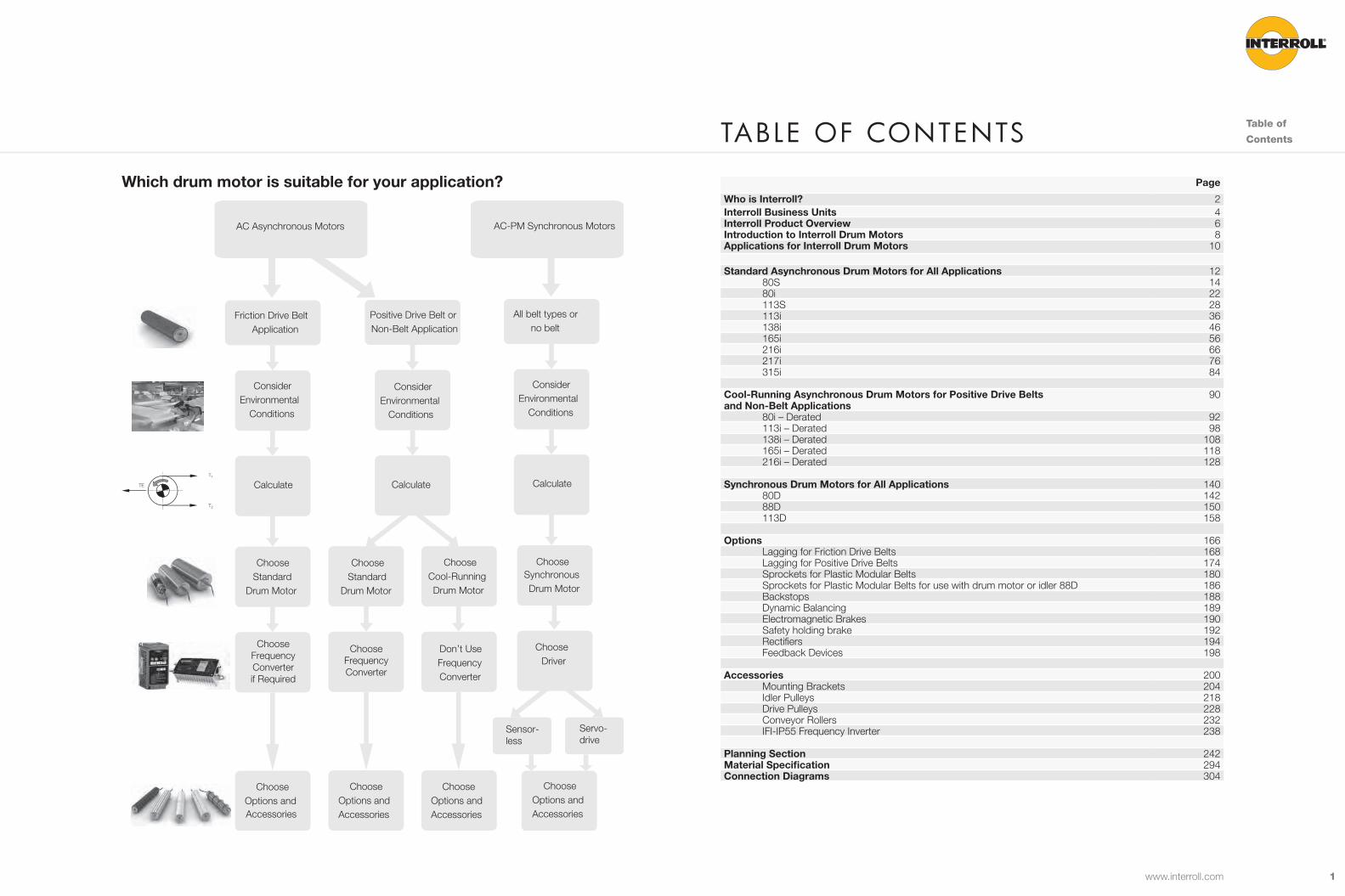
Friction Drive Belt Application
Positive Drive Belt or Non-Belt Application
Choose Options and Accessories
ChooseCool-RunningDrum Motor
ChooseStandard
Drum Motor
Choose Options and Accessories
Choose Options and Accessories
ChooseStandard
Drum Motor
Consider Environmental
Conditions
Consider Environmental
Conditions
ChooseFrequencyConverterif Required
Don’t UseFrequency Converter
CalculateCalculate
ChooseFrequencyConverter
All belt types or no belt
Consider Environmental
Conditions
Calculate
Conditions
SynchronousDrum Motor
Choose Driver
Choose
Servo- drive
Sensor- less
AC Asynchronous Motors AC-PM Synchronous Motors
Page
Who is Interroll? 2Interroll Business Units 4Interroll Product Overview 6Introduction to Interroll Drum Motors 8Applications for Interroll Drum Motors 10
Standard Asynchronous Drum Motors for All Applications 1280S 1480i 22113S 28113i 36138i 46165i 56216i 66217i 76315i 84
Cool-Running Asynchronous Drum Motors for Positive Drive Belts and Non-Belt Applications
90
80i – Derated 92113i – Derated 98138i – Derated 108165i – Derated 118216i – Derated 128
Synchronous Drum Motors for All Applications 14080D 14288D 150113D 158
Options 166Lagging for Friction Drive Belts 168Lagging for Positive Drive Belts 174Sprockets for Plastic Modular Belts 180Sprockets for Plastic Modular Belts for use with drum motor or idler 88D 186Backstops 188Dynamic Balancing 189Electromagnetic Brakes 190Safety holding brake 192Rectifiers 194Feedback Devices 198
Accessories 200Mounting Brackets 204Idler Pulleys 218Drive Pulleys 228Conveyor Rollers 232IFI-IP55 Frequency Inverter 238
Planning Section 242Material Specification 294Connection Diagrams 304
Which drum motor is suitable for your application?

32 www.interroll.com
The Interroll solutions are used primarily within the area
of food processing, airport logistics, postal services,
distribution and in various segments of industry. The
products include easy-to-integrate drive solutions such
as drum motors for belt conveyors, DC-powered and
non-powered rollers for conveyor systems; energy-
efficient flow storage modules for compact pallet/
container racking systems in distribution centres;
crossbelt sorters, belt curves and other user-friendly
conveyor modules for cost-efficient material flow
systems.
Interroll serves more than 23,000 customers, mainly
multinational companies and system integrators as well
as engineering specialists, regional plant manufacturers
and users.
Interroll has 1,500 employees working in 28 companies
and is listed on the SIX Swiss Exchange. Managed by
a strategic holding company based in Sant‘Antonino,
Switzerland, the group operates with two business
divisions: “Global Sales & Service“ markets and
distributes the full range of Interroll products according
to specified target markets, while “Products &
Technology“ oversees the global Centres of Excellence
and other production sites, with responsibilities
ranging from R&D, Product Management and
Strategic Purchasing to Production Technology and
Manufacturing.
the Interroll WorlDWIDe Group
Interroll is one of the world‘s
leading manufacturers of key
products for unit load handling
systems, internal logistics and
automation.
Interroll
Company
Profile
Interroll‘s key markets Food &
Beverage Industry
Manufacturing Parcel, Postal
and Courier
Distribution Airport Industry Health Care Industry
54 www.interroll.com
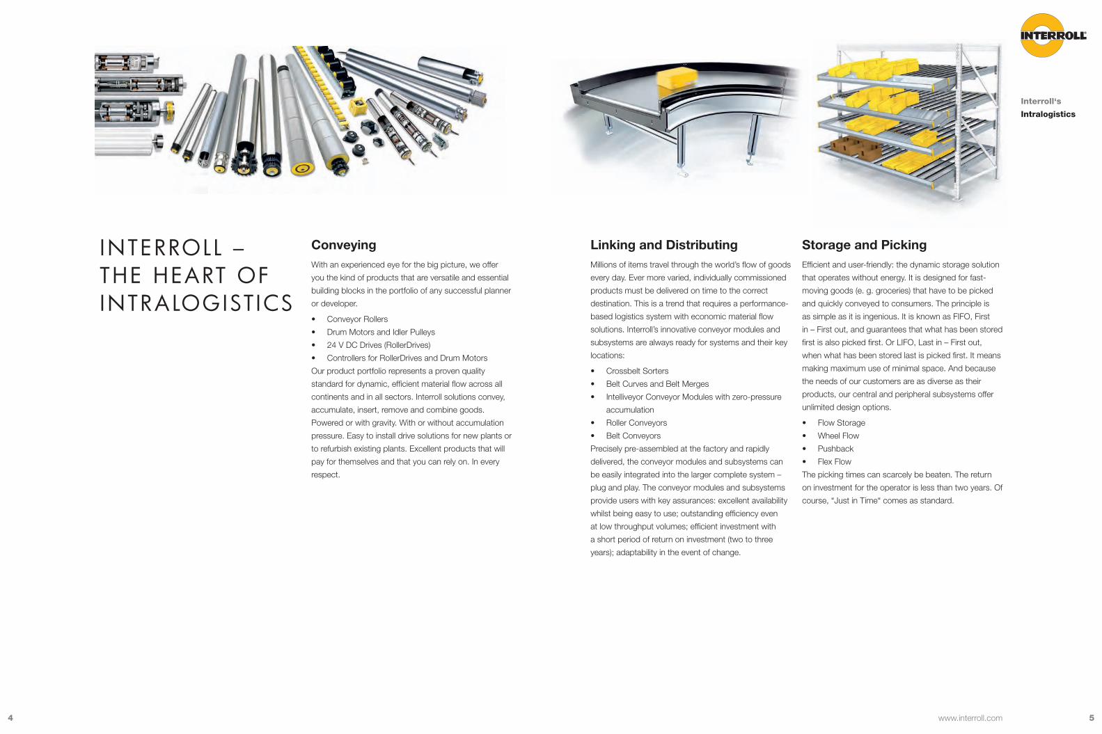
Linking and DistributingMillions of items travel through the world’s flow of goods
every day. Ever more varied, individually commissioned
products must be delivered on time to the correct
destination. This is a trend that requires a performance-
based logistics system with economic material flow
solutions. Interroll’s innovative conveyor modules and
subsystems are always ready for systems and their key
locations:
• Crossbelt Sorters
• Belt Curves and Belt Merges
• Intelliveyor Conveyor Modules with zero-pressure
accumulation
• Roller Conveyors
• Belt Conveyors
Precisely pre-assembled at the factory and rapidly
delivered, the conveyor modules and subsystems can
be easily integrated into the larger complete system –
plug and play. The conveyor modules and subsystems
provide users with key assurances: excellent availability
whilst being easy to use; outstanding efficiency even
at low throughput volumes; efficient investment with
a short period of return on investment (two to three
years); adaptability in the event of change.
Storage and PickingEfficient and user-friendly: the dynamic storage solution
that operates without energy. It is designed for fast-
moving goods (e. g. groceries) that have to be picked
and quickly conveyed to consumers. The principle is
as simple as it is ingenious. It is known as FIFO, First
in – First out, and guarantees that what has been stored
first is also picked first. Or LIFO, Last in – First out,
when what has been stored last is picked first. It means
making maximum use of minimal space. And because
the needs of our customers are as diverse as their
products, our central and peripheral subsystems offer
unlimited design options.
• Flow Storage
• Wheel Flow
• Pushback
• Flex Flow
The picking times can scarcely be beaten. The return
on investment for the operator is less than two years. Of
course, “Just in Time“ comes as standard.
Interroll – the heart of IntraloGIstICs
ConveyingWith an experienced eye for the big picture, we offer
you the kind of products that are versatile and essential
building blocks in the portfolio of any successful planner
or developer.
• Conveyor Rollers
• Drum Motors and Idler Pulleys
• 24 V DC Drives (RollerDrives)
• Controllers for RollerDrives and Drum Motors
Our product portfolio represents a proven quality
standard for dynamic, efficient material flow across all
continents and in all sectors. Interroll solutions convey,
accumulate, insert, remove and combine goods.
Powered or with gravity. With or without accumulation
pressure. Easy to install drive solutions for new plants or
to refurbish existing plants. Excellent products that will
pay for themselves and that you can rely on. In every
respect.
Interroll‘s
Intralogistics

76
Interroll – the most Global provIDer of key proDuCts for materIal hanDl InG solutIons1 FIFO - Pallet flow storage modules (Conveyor Rollers)
2 LIFO - Pallet flow storage modules (Conveyor Rollers)
3 LIFO - Pallet flow storage modules (Cart Pushback)
4 Order picking racking with Carton Flow (Roller Track)
5 Order picking racking with Flex Flow
6 Drum Motors, Idler Pulleys, brackets
7 24 V DC RollerDrives and Controls
8 Conveyor Rollers and Accessories
9 Idler Pulleys
10 Crossbelt Sorters
11 Belt Curves
12 Belt Conveyor Modules
13 Intelliveyor Modules for zero pressure accumulation (ZPA) Conveyors
Standard Drum Motors p 12Cool-Running Drum Motors p 90Synchronous Drum Motors p 140Options p 166Accessories p 200
Interroll
Product
Overview
Visit www.interroll.com for information on other Interroll productsRefer to the Planning Section from p 242 for help with planning and design
1
23
4
13
13
8
7
10
11
5
6
12
9
98 www.interroll.com
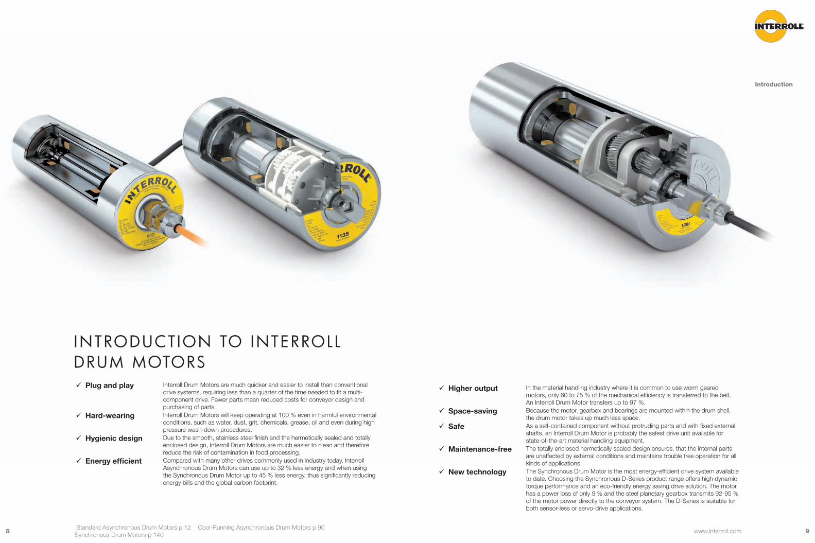
IntroDuCtIon to Interroll Drum motors
9 Plug and play Interroll Drum Motors are much quicker and easier to install than conventional drive systems, requiring less than a quarter of the time needed to fit a multi-component drive. Fewer parts mean reduced costs for conveyor design and purchasing of parts.
9 Hard-wearing Interroll Drum Motors will keep operating at 100 % even in harmful environmental conditions, such as water, dust, grit, chemicals, grease, oil and even during high pressure wash-down procedures.
9 Hygienic design Due to the smooth, stainless steel finish and the hermetically sealed and totally enclosed design, Interroll Drum Motors are much easier to clean and therefore reduce the risk of contamination in food processing.
9 Energy efficient Compared with many other drives commonly used in industry today, Interroll Asynchronous Drum Motors can use up to 32 % less energy and when using the Synchronous Drum Motor up to 45 % less energy, thus significantly reducing energy bills and the global carbon footprint.
Introduction
Standard Asynchronous Drum Motors p 12 Cool-Running Asynchronous Drum Motors p 90 Synchronous Drum Motors p 140
9 Higher output In the material handling industry where it is common to use worm geared motors, only 60 to 75 % of the mechanical efficiency is transferred to the belt. An Interroll Drum Motor transfers up to 97 %.
9 Space-saving Because the motor, gearbox and bearings are mounted within the drum shell, the drum motor takes up much less space.
9 Safe As a self-contained component without protruding parts and with fixed external shafts, an Interroll Drum Motor is probably the safest drive unit available for state-of-the-art material handling equipment.
9 Maintenance-free The totally enclosed hermetically sealed design ensures, that the internal parts are unaffected by external conditions and maintains trouble free operation for all kinds of applications.
9 New technology The Synchronous Drum Motor is the most energy-efficient drive system available to date. Choosing the Synchronous D-Series product range offers high dynamic torque performance and an eco-friendly energy saving drive solution. The motor has a power loss of only 9 % and the steel planetary gearbox transmits 92-95 % of the motor power directly to the conveyor system. The D-Series is suitable for both sensor-less or servo-drive applications.
1110 Refer to the Planning Section on p 242 for help with planning and design
 Standard Drum Motor without frequency converter p 12• For friction drive belt applications
 Standard Drum Motor with frequency converter p 12• For friction drive belt applications
• For plastic modular belt applications
• For positive drive solid homogeneous belts
• For non-belt applications  Cool-running Drum Motor p 90
• For plastic modular belt applications
• For positive drive solid homogeneous belts
• For non-belt applications  Synchronous Drum Motor p 140
• For all belt types or no belt using either a
sensor-less frequency inverter or servo-driver
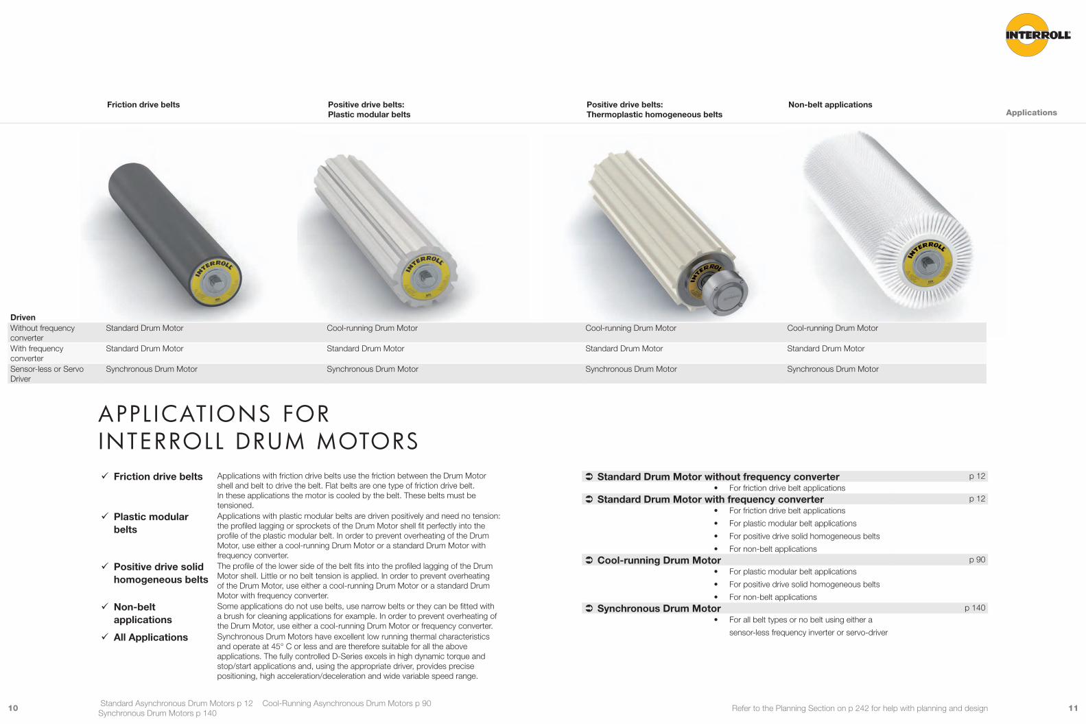
9 Friction drive belts Applications with friction drive belts use the friction between the Drum Motor shell and belt to drive the belt. Flat belts are one type of friction drive belt. In these applications the motor is cooled by the belt. These belts must be tensioned.
9 Plastic modular belts
Applications with plastic modular belts are driven positively and need no tension: the profiled lagging or sprockets of the Drum Motor shell fit perfectly into the profile of the plastic modular belt. In order to prevent overheating of the Drum Motor, use either a cool-running Drum Motor or a standard Drum Motor with frequency converter.
9 Positive drive solid homogeneous belts
The profile of the lower side of the belt fits into the profiled lagging of the Drum Motor shell. Little or no belt tension is applied. In order to prevent overheating of the Drum Motor, use either a cool-running Drum Motor or a standard Drum Motor with frequency converter.
9 Non-belt applications
Some applications do not use belts, use narrow belts or they can be fitted with a brush for cleaning applications for example. In order to prevent overheating of the Drum Motor, use either a cool-running Drum Motor or frequency converter.
9 All Applications Synchronous Drum Motors have excellent low running thermal characteristics and operate at 45° C or less and are therefore suitable for all the above applications. The fully controlled D-Series excels in high dynamic torque and stop/start applications and, using the appropriate driver, provides precise positioning, high acceleration/deceleration and wide variable speed range.
Applications
Standard Asynchronous Drum Motors p 12 Cool-Running Asynchronous Drum Motors p 90 Synchronous Drum Motors p 140
appl ICatIons for Interroll Drum motors
Friction drive belts Positive drive belts: Plastic modular belts
Positive drive belts: Thermoplastic homogeneous belts
Non-belt applications
DrivenWithout frequency converter
Standard Drum Motor Cool-running Drum Motor Cool-running Drum Motor Cool-running Drum Motor
With frequency converter
Standard Drum Motor Standard Drum Motor Standard Drum Motor Standard Drum Motor
Sensor-less or Servo Driver
Synchronous Drum Motor Synchronous Drum Motor Synchronous Drum Motor Synchronous Drum Motor
1312 Refer to the Planning Section on p 242 for help with planning and design
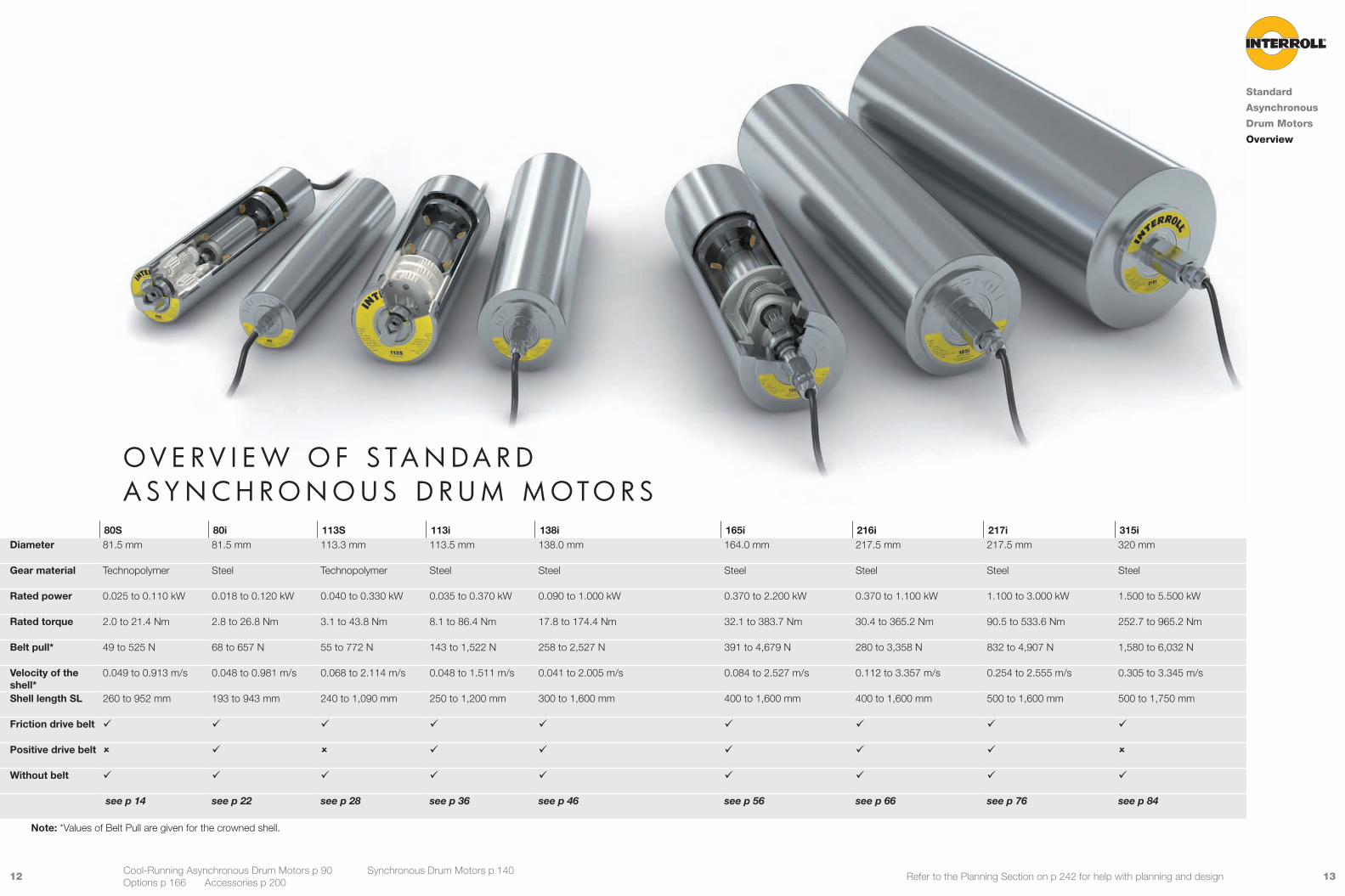
o v e r v I e W o f s ta n D a r D a sy n C h r o n o u s D r u m m oto r s
80S 80i 113S 113i 138i 165i 216i 217i 315iDiameter 81.5 mm 81.5 mm 113.3 mm 113.5 mm 138.0 mm 164.0 mm 217.5 mm 217.5 mm 320 mm
Gear material Technopolymer Steel Technopolymer Steel Steel Steel Steel Steel Steel
Rated power 0.025 to 0.110 kW 0.018 to 0.120 kW 0.040 to 0.330 kW 0.035 to 0.370 kW 0.090 to 1.000 kW 0.370 to 2.200 kW 0.370 to 1.100 kW 1.100 to 3.000 kW 1.500 to 5.500 kW
Rated torque 2.0 to 21.4 Nm 2.8 to 26.8 Nm 3.1 to 43.8 Nm 8.1 to 86.4 Nm 17.8 to 174.4 Nm 32.1 to 383.7 Nm 30.4 to 365.2 Nm 90.5 to 533.6 Nm 252.7 to 965.2 Nm
Belt pull* 49 to 525 N 68 to 657 N 55 to 772 N 143 to 1,522 N 258 to 2,527 N 391 to 4,679 N 280 to 3,358 N 832 to 4,907 N 1,580 to 6,032 N
Velocity of the shell*
0.049 to 0.913 m/s 0.048 to 0.981 m/s 0.068 to 2.114 m/s 0.048 to 1.511 m/s 0.041 to 2.005 m/s 0.084 to 2.527 m/s 0.112 to 3.357 m/s 0.254 to 2.555 m/s 0.305 to 3.345 m/s
Shell length SL 260 to 952 mm 193 to 943 mm 240 to 1,090 mm 250 to 1,200 mm 300 to 1,600 mm 400 to 1,600 mm 400 to 1,600 mm 500 to 1,600 mm 500 to 1,750 mm
Friction drive belt 9 9 9 9 9 9 9 9 9
Positive drive belt û 9 û 9 9 9 9 9 û
Without belt 9 9 9 9 9 9 9 9 9
see p 14 see p 22 see p 28 see p 36 see p 46 see p 56 see p 66 see p 76 see p 84
Note: *Values of Belt Pull are given for the crowned shell.
Standard
Asynchronous
Drum Motors
Overview
Cool-Running Asynchronous Drum Motors p 90 Synchronous Drum Motors p 140 Options p 166 Accessories p 200
1514 Refer to the Planning Section on p 242 for help with planning and design
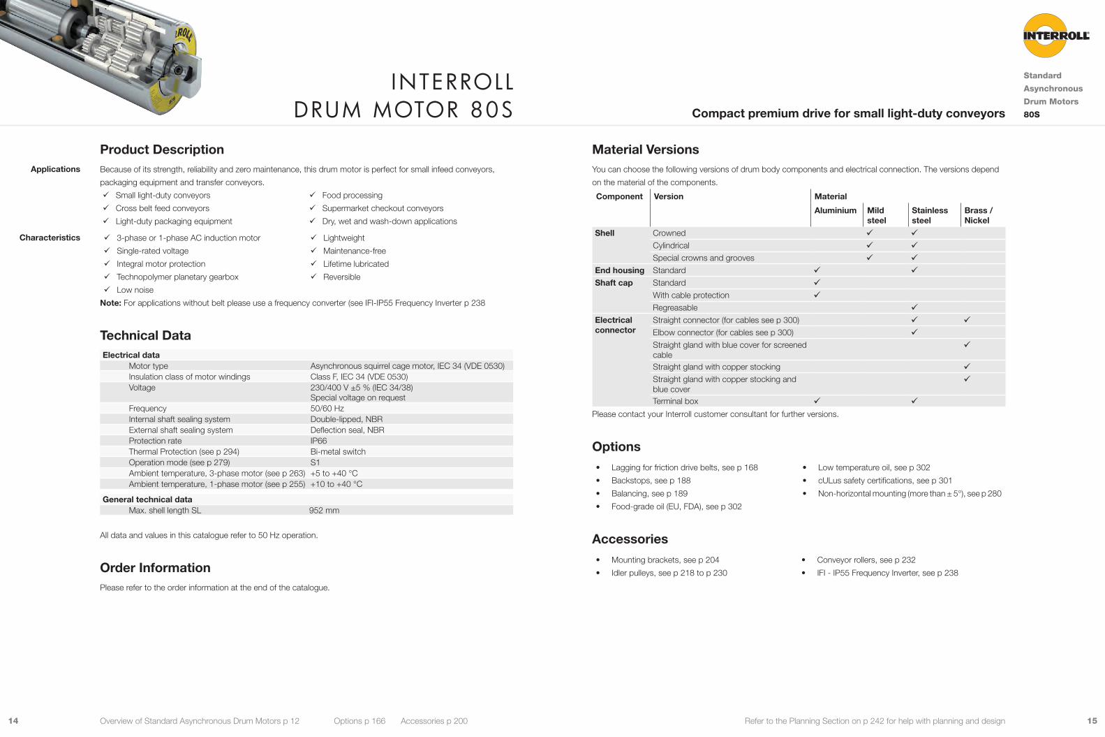
Material VersionsYou can choose the following versions of drum body components and electrical connection. The versions depend
on the material of the components.
Component Version Material
Aluminium Mild steel
Stainless steel
Brass / Nickel
Shell Crowned 9 9Cylindrical 9 9Special crowns and grooves 9 9
End housing Standard 9 9Shaft cap Standard 9
With cable protection 9Regreasable 9
Electrical connector
Straight connector (for cables see p 300) 9 9Elbow connector (for cables see p 300) 9Straight gland with blue cover for screened cable
9
Straight gland with copper stocking 9Straight gland with copper stocking and blue cover
9
Terminal box 9 9Please contact your Interroll customer consultant for further versions.
Options• Lagging for friction drive belts, see p 168
• Backstops, see p 188
• Balancing, see p 189
• Food-grade oil (EU, FDA), see p 302
• Low temperature oil, see p 302
• cULus safety certifications, see p 301
• Non-horizontal mounting (more than ± 5°), see p 280
Accessories• Mounting brackets, see p 204
• Idler pulleys, see p 218 to p 230
• Conveyor rollers, see p 232
• IFI - IP55 Frequency Inverter, see p 238
Product DescriptionBecause of its strength, reliability and zero maintenance, this drum motor is perfect for small infeed conveyors,
packaging equipment and transfer conveyors.
9 Small light-duty conveyors
9 Cross belt feed conveyors
9 Light-duty packaging equipment
9 Food processing
9 Supermarket checkout conveyors
9 Dry, wet and wash-down applications
9 3-phase or 1-phase AC induction motor
9 Single-rated voltage
9 Integral motor protection
9 Technopolymer planetary gearbox
9 Low noise
9 Lightweight
9 Maintenance-free
9 Lifetime lubricated
9 Reversible
Note: For applications without belt please use a frequency converter (see IFI-IP55 Frequency Inverter p 238
Technical DataElectrical data
Motor type Asynchronous squirrel cage motor, IEC 34 (VDE 0530)Insulation class of motor windings Class F, IEC 34 (VDE 0530)Voltage 230/400 V ±5 % (IEC 34/38)
Special voltage on requestFrequency 50/60 HzInternal shaft sealing system Double-lipped, NBRExternal shaft sealing system Deflection seal, NBRProtection rate IP66Thermal Protection (see p 294) Bi-metal switchOperation mode (see p 279) S1Ambient temperature, 3-phase motor (see p 263) +5 to +40 °CAmbient temperature, 1-phase motor (see p 255) +10 to +40 °C
General technical data Max. shell length SL 952 mm
All data and values in this catalogue refer to 50 Hz operation.
Order InformationPlease refer to the order information at the end of the catalogue.
Applications
Characteristics
Interroll Drum motor 80s
Standard
Asynchronous
Drum Motors
80SCompact premium drive for small light-duty conveyors
Overview of Standard Asynchronous Drum Motors p 12 Options p 166 Accessories p 200
1716 Refer to the Planning Section on p 242 for help with planning and design
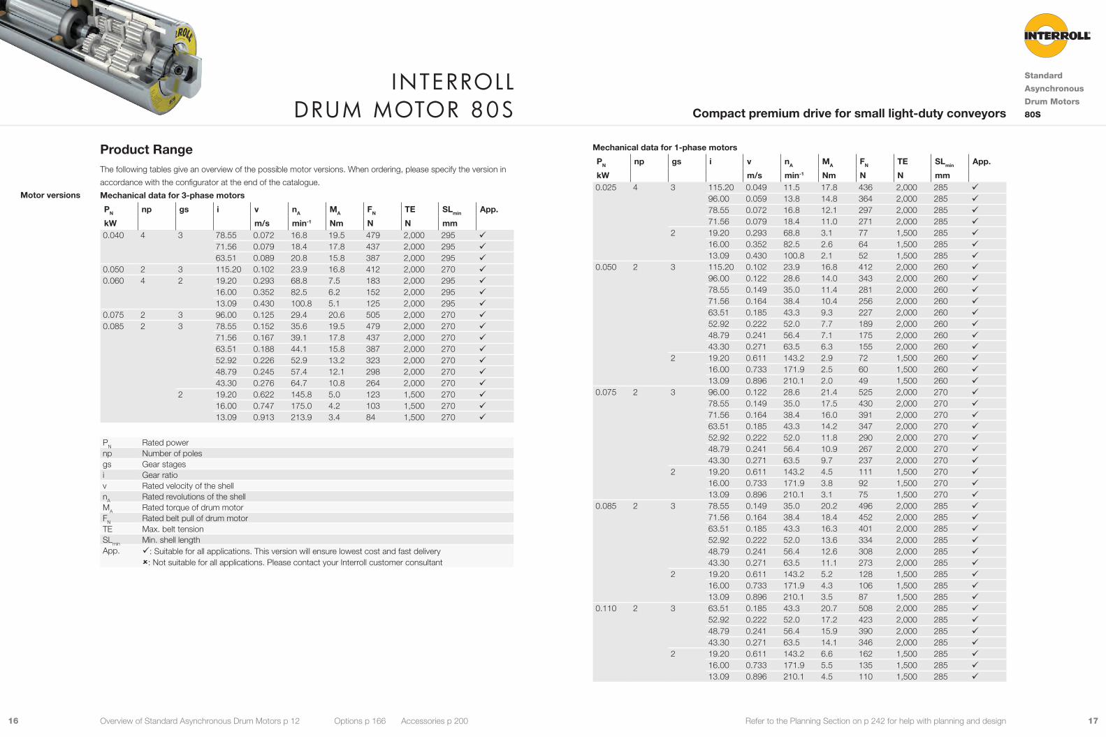
Mechanical data for 1-phase motors
PN np gs i v nA MA FN TE SLmin App.
kW m/s min-1 Nm N N mm 0.025 4 3 115.20 0.049 11.5 17.8 436 2,000 285 9
96.00 0.059 13.8 14.8 364 2,000 285 978.55 0.072 16.8 12.1 297 2,000 285 971.56 0.079 18.4 11.0 271 2,000 285 9
2 19.20 0.293 68.8 3.1 77 1,500 285 916.00 0.352 82.5 2.6 64 1,500 285 913.09 0.430 100.8 2.1 52 1,500 285 9
0.050 2 3 115.20 0.102 23.9 16.8 412 2,000 260 996.00 0.122 28.6 14.0 343 2,000 260 978.55 0.149 35.0 11.4 281 2,000 260 971.56 0.164 38.4 10.4 256 2,000 260 963.51 0.185 43.3 9.3 227 2,000 260 952.92 0.222 52.0 7.7 189 2,000 260 948.79 0.241 56.4 7.1 175 2,000 260 943.30 0.271 63.5 6.3 155 2,000 260 9
2 19.20 0.611 143.2 2.9 72 1,500 260 916.00 0.733 171.9 2.5 60 1,500 260 913.09 0.896 210.1 2.0 49 1,500 260 9
0.075 2 3 96.00 0.122 28.6 21.4 525 2,000 270 978.55 0.149 35.0 17.5 430 2,000 270 971.56 0.164 38.4 16.0 391 2,000 270 963.51 0.185 43.3 14.2 347 2,000 270 952.92 0.222 52.0 11.8 290 2,000 270 948.79 0.241 56.4 10.9 267 2,000 270 943.30 0.271 63.5 9.7 237 2,000 270 9
2 19.20 0.611 143.2 4.5 111 1,500 270 916.00 0.733 171.9 3.8 92 1,500 270 913.09 0.896 210.1 3.1 75 1,500 270 9
0.085 2 3 78.55 0.149 35.0 20.2 496 2,000 285 971.56 0.164 38.4 18.4 452 2,000 285 963.51 0.185 43.3 16.3 401 2,000 285 952.92 0.222 52.0 13.6 334 2,000 285 948.79 0.241 56.4 12.6 308 2,000 285 943.30 0.271 63.5 11.1 273 2,000 285 9
2 19.20 0.611 143.2 5.2 128 1,500 285 916.00 0.733 171.9 4.3 106 1,500 285 913.09 0.896 210.1 3.5 87 1,500 285 9
0.110 2 3 63.51 0.185 43.3 20.7 508 2,000 285 952.92 0.222 52.0 17.2 423 2,000 285 948.79 0.241 56.4 15.9 390 2,000 285 943.30 0.271 63.5 14.1 346 2,000 285 9
2 19.20 0.611 143.2 6.6 162 1,500 285 916.00 0.733 171.9 5.5 135 1,500 285 913.09 0.896 210.1 4.5 110 1,500 285 9
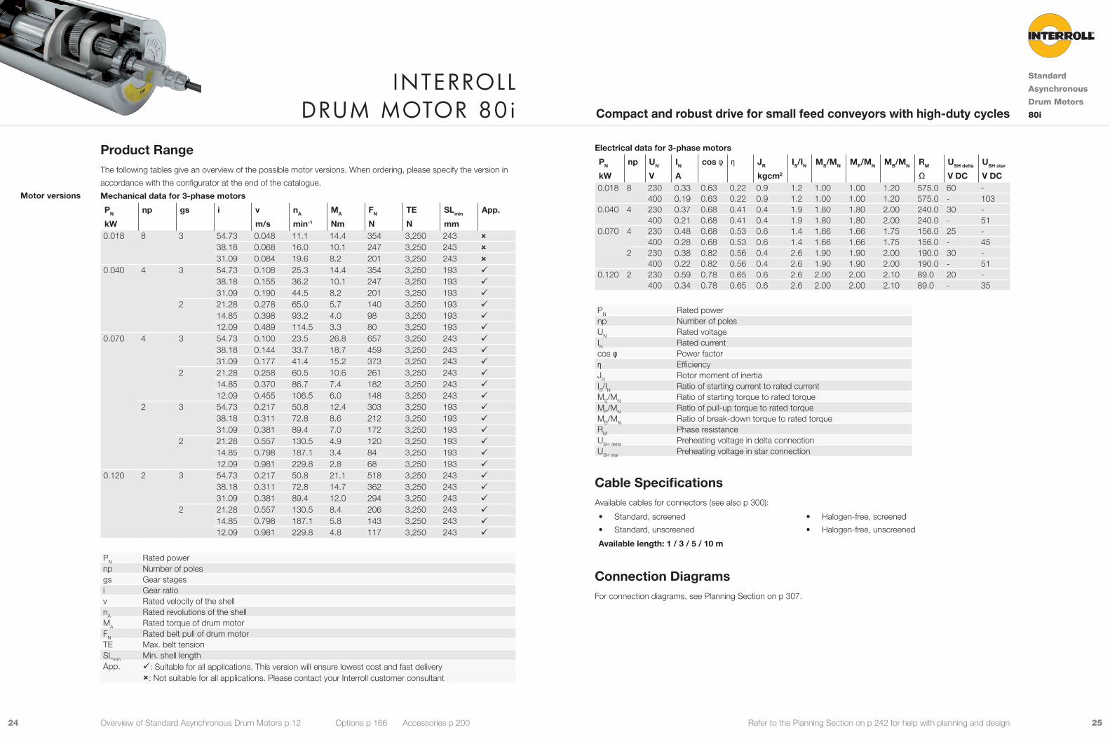
Product RangeThe following tables give an overview of the possible motor versions. When ordering, please specify the version in
accordance with the configurator at the end of the catalogue.
Mechanical data for 3-phase motors
PN np gs i v nA MA FN TE SLmin App.
kW m/s min-1 Nm N N mm 0.040 4 3 78.55 0.072 16.8 19.5 479 2,000 295 9
71.56 0.079 18.4 17.8 437 2,000 295 963.51 0.089 20.8 15.8 387 2,000 295 9
0.050 2 3 115.20 0.102 23.9 16.8 412 2,000 270 90.060 4 2 19.20 0.293 68.8 7.5 183 2,000 295 9
16.00 0.352 82.5 6.2 152 2,000 295 913.09 0.430 100.8 5.1 125 2,000 295 9
0.075 2 3 96.00 0.125 29.4 20.6 505 2,000 270 90.085 2 3 78.55 0.152 35.6 19.5 479 2,000 270 9
71.56 0.167 39.1 17.8 437 2,000 270 963.51 0.188 44.1 15.8 387 2,000 270 952.92 0.226 52.9 13.2 323 2,000 270 948.79 0.245 57.4 12.1 298 2,000 270 943.30 0.276 64.7 10.8 264 2,000 270 9
2 19.20 0.622 145.8 5.0 123 1,500 270 916.00 0.747 175.0 4.2 103 1,500 270 913.09 0.913 213.9 3.4 84 1,500 270 9
PN Rated powernp Number of polesgs Gear stagesi Gear ratiov Rated velocity of the shellnA Rated revolutions of the shellMA Rated torque of drum motorFN Rated belt pull of drum motorTE Max. belt tensionSLmin Min. shell lengthApp. 9: Suitable for all applications. This version will ensure lowest cost and fast delivery
û: Not suitable for all applications. Please contact your Interroll customer consultant
Motor versions
Interroll Drum motor 80s
Standard
Asynchronous
Drum Motors
80SCompact premium drive for small light-duty conveyors
Overview of Standard Asynchronous Drum Motors p 12 Options p 166 Accessories p 200

1918 Refer to the Planning Section on p 242 for help with planning and design
Cable SpecificationsAvailable cables for connectors (see also p 300):
• Standard, screened
• Standard, unscreened
• Halogen-free, screened
• Halogen-free, unscreened
Available length: 1 / 3 / 5 m
Note: Only one voltage available with screened and halogen-free cables.
Connection DiagramsFor connection diagrams, see Planning Section on p 304.
Electrical data for 3-phase motors
PN np UN IN cos φ η JR IS/IN MS/MN MP/MN MB/MN RM USH delta USH star
kW V A kgcm2 Ω V DC V DC0.040 4 230 0.71 0.65 0.21 1.0 1.8 1.60 1.60 1.60 156.5 36 -
400 0.43 0.65 0.21 1.0 1.8 1.60 1.60 1.60 156.5 - 660.050 2 230 0.46 0.57 0.47 1.0 4.6 3.82 3.82 3.82 111.3 15 -
400 0.22 0.71 0.45 1.0 4.4 2.35 2.35 2.53 171.0 - 400.060 4 230 0.79 0.65 0.29 1.0 1.8 1.60 1.60 1.60 156.5 40 -
400 0.46 0.65 0.29 1.0 1.8 1.60 1.60 1.60 156.5 - 700.075 2 230 0.51 0.69 0.53 1.0 4.6 2.50 2.50 2.50 111.3 20 -
400 0.30 0.70 0.51 1.0 4.5 2.50 2.50 2.50 113.0 - 360.085 2 230 0.53 0.73 0.55 1.0 4.6 2.24 2.24 2.24 111.3 22 -
400 0.32 0.74 0.52 1.0 4.5 2.24 2.24 2.24 113.0 - 40
Electrical data for 1-phase motors
PN np UN IN cos φ η JR IS/IN MS/MN MP/MN MB/MN RM USH ~ Cr
kW V A kgcm2 Ω V DC µF0.025 4 230 0.39 1.00 0.28 1.2 2.2 1.11 1.11 1.37 150.0 44 30.050 2 230 0.54 1.00 0.40 0.9 3.1 0.94 0.94 1.71 82.0 33 30.075 2 230 0.68 1.00 0.48 1.0 3.2 0.74 0.74 1.37 66.0 34 40.085 2 230 0.73 0.98 0.53 1.3 5.2 0.93 0.93 1.60 52.0 28 60.110 2 230 0.94 1.00 0.51 1.2 2.0 0.73 0.73 1.15 51.0 36 8
PN Rated powernp Number of polesUN Rated voltageIN Rated currentcos φ Power factorη EfficiencyJR Rotor moment of inertiaIS/IN Ratio of starting current to rated currentMS/MN Ratio of starting torque to rated torqueMP/MN Ratio of pull-up torque to rated torqueMB/MN Ratio of break-down torque to rated torqueRM Phase resistanceUSH delta Preheating voltage in delta connectionUSH star Preheating voltage in star connectionUSH ∿ Preheating voltage in single phaseCr Capacitor size
Interroll Drum motor 80s
Standard
Asynchronous
Drum Motors
80SCompact premium drive for small light-duty conveyors
Overview of Standard Asynchronous Drum Motors p 12 Options p 166 Accessories p 200
2120 Refer to the Planning Section on p 242 for help with planning and design
25
18
Ø30
27
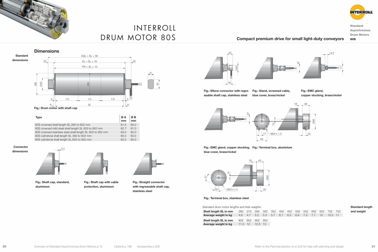
Fig.: Elbow connector with regre-
asable shaft cap, stainless steel
Fig.: Gland, screened cable,
blue cover, brass/nickel
Fig.: EMC gland,
copper stocking, brass/nickel
27
65
17 22
46
Ø95
14
M20 x 1.5
18
Fig.: EMC gland, copper stocking,
blue cover, brass/nickel
Fig.: Terminal box, aluminium
47
20°
14
M20 x 1.5
18
25
43
Ø99
Fig.: Terminal box, stainless steel
Standard drum motor lengths and their weights:
Shell length SL in mm 260 270 285 302 352 402 452 502 552 602 652 702 752Average weight in kg 4.6 4.7 5.2 5.3 5.7 6.1 6.5 6.9 7.3 7.7 10 10.5 11
Shell length SL in mm 802 852 902 952Average weight in kg 11.5 12 12.5 13
Standard length
and weight
Dimensions
20
8 SL
1/31/31/3
ØB
Ø45 ØA
8
20
FW = SL + 10
EL = SL + 16
AGL = SL + 56
5 5
21
35
Fig.: Drum motor with shaft cap
Type Ø Amm
Ø Bmm
80S crowned shell length SL 260 to 602 mm 81.5 80.080S crowned mild steel shell length SL 603 to 952 mm 82.7 81.080S crowned stainless steel shell length SL 603 to 952 mm 83.0 80.080S cylindrical shell length SL 260 to 602 mm 80.5 80.580S cylindrical shell length SL 603 to 952 mm 83.0 83.0
2.2 20 ?
?
Fig.: Shaft cap, standard,
aluminium
Fig.: Shaft cap with cable
protection, aluminium
Fig.: Straight connector
with regreasable shaft cap,
stainless steel
Standard
dimensions
Connector
dimensions
Interroll Drum motor 80s
Standard
Asynchronous
Drum Motors
80SCompact premium drive for small light-duty conveyors
Overview of Standard Asynchronous Drum Motors p 12 Options p 166 Accessories p 200
17
14.5
2322 Refer to the Planning Section on p 242 for help with planning and design
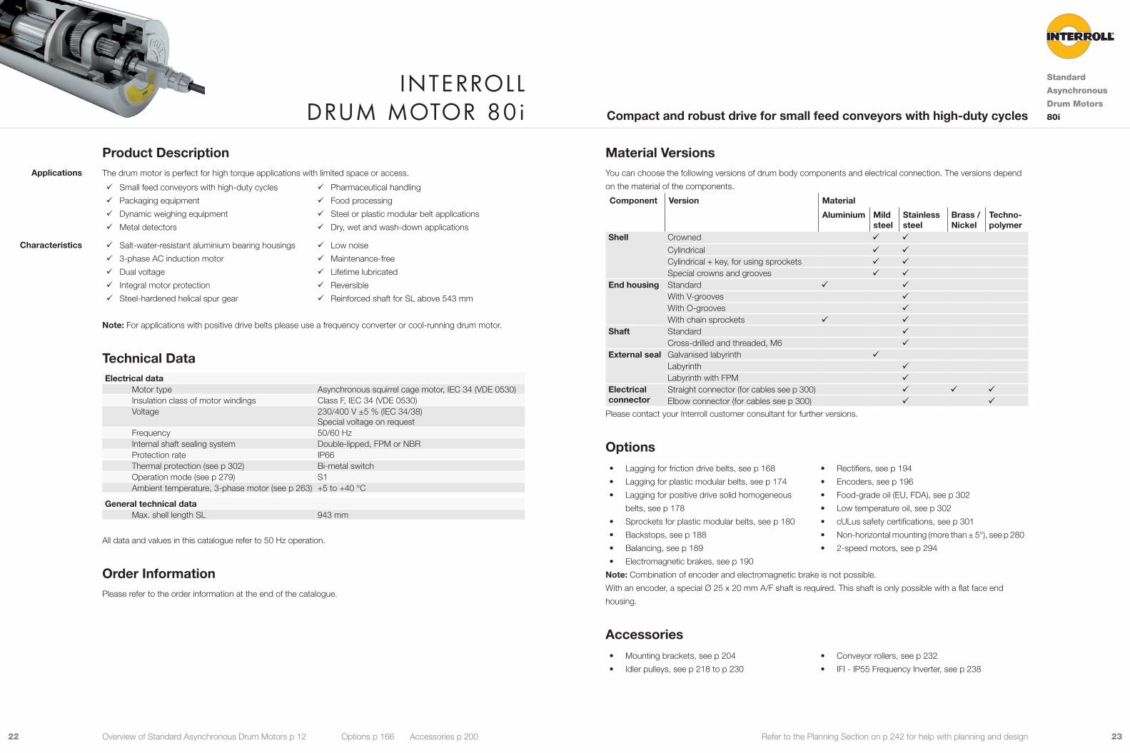
Material VersionsYou can choose the following versions of drum body components and electrical connection. The versions depend
on the material of the components.
Component Version Material
Aluminium Mild steel
Stainless steel
Brass / Nickel
Techno-polymer
Shell Crowned 9 9Cylindrical 9 9Cylindrical + key, for using sprockets 9 9Special crowns and grooves 9 9
End housing Standard 9 9With V-grooves 9With O-grooves 9With chain sprockets 9 9
Shaft Standard 9Cross-drilled and threaded, M6 9
External seal Galvanised labyrinth 9Labyrinth 9Labyrinth with FPM 9
Electrical connector
Straight connector (for cables see p 300) 9 9 9Elbow connector (for cables see p 300) 9 9
Please contact your Interroll customer consultant for further versions.
Options• Lagging for friction drive belts, see p 168
• Lagging for plastic modular belts, see p 174
• Lagging for positive drive solid homogeneous
belts, see p 178
• Sprockets for plastic modular belts, see p 180
• Backstops, see p 188
• Balancing, see p 189
• Electromagnetic brakes, see p 190
• Rectifiers, see p 194
• Encoders, see p 196
• Food-grade oil (EU, FDA), see p 302
• Low temperature oil, see p 302
• cULus safety certifications, see p 301
• Non-horizontal mounting (more than ± 5°), see p 280
• 2-speed motors, see p 294
Note: Combination of encoder and electromagnetic brake is not possible.
With an encoder, a special Ø 25 x 20 mm A/F shaft is required. This shaft is only possible with a flat face end
housing.
Accessories• Mounting brackets, see p 204
• Idler pulleys, see p 218 to p 230
• Conveyor rollers, see p 232
• IFI - IP55 Frequency Inverter, see p 238
Product DescriptionThe drum motor is perfect for high torque applications with limited space or access.
9 Small feed conveyors with high-duty cycles
9 Packaging equipment
9 Dynamic weighing equipment
9 Metal detectors
9 Pharmaceutical handling
9 Food processing
9 Steel or plastic modular belt applications
9 Dry, wet and wash-down applications
9 Salt-water-resistant aluminium bearing housings
9 3-phase AC induction motor
9 Dual voltage
9 Integral motor protection
9 Steel-hardened helical spur gear
9 Low noise
9 Maintenance-free
9 Lifetime lubricated
9 Reversible
9 Reinforced shaft for SL above 543 mm
Note: For applications with positive drive belts please use a frequency converter or cool-running drum motor.
Technical DataElectrical data
Motor type Asynchronous squirrel cage motor, IEC 34 (VDE 0530)Insulation class of motor windings Class F, IEC 34 (VDE 0530)Voltage 230/400 V ±5 % (IEC 34/38)
Special voltage on requestFrequency 50/60 HzInternal shaft sealing system Double-lipped, FPM or NBRProtection rate IP66Thermal protection (see p 302) Bi-metal switchOperation mode (see p 279) S1Ambient temperature, 3-phase motor (see p 263) +5 to +40 °C
General technical data Max. shell length SL 943 mm
All data and values in this catalogue refer to 50 Hz operation.
Order InformationPlease refer to the order information at the end of the catalogue.
Applications
Characteristics
Interroll Drum motor 80i
Standard
Asynchronous
Drum Motors
80iCompact and robust drive for small feed conveyors with high-duty cycles
Overview of Standard Asynchronous Drum Motors p 12 Options p 166 Accessories p 200
2524 Refer to the Planning Section on p 242 for help with planning and design
Electrical data for 3-phase motors
PN np UN IN cos φ η JR IS/IN MS/MN MP/MN MB/MN RM USH delta USH star
kW V A kgcm2 Ω V DC V DC0.018 8 230 0.33 0.63 0.22 0.9 1.2 1.00 1.00 1.20 575.0 60 -
400 0.19 0.63 0.22 0.9 1.2 1.00 1.00 1.20 575.0 - 1030.040 4 230 0.37 0.68 0.41 0.4 1.9 1.80 1.80 2.00 240.0 30 -
400 0.21 0.68 0.41 0.4 1.9 1.80 1.80 2.00 240.0 - 510.070 4 230 0.48 0.68 0.53 0.6 1.4 1.66 1.66 1.75 156.0 25 -
400 0.28 0.68 0.53 0.6 1.4 1.66 1.66 1.75 156.0 - 452 230 0.38 0.82 0.56 0.4 2.6 1.90 1.90 2.00 190.0 30 -
400 0.22 0.82 0.56 0.4 2.6 1.90 1.90 2.00 190.0 - 510.120 2 230 0.59 0.78 0.65 0.6 2.6 2.00 2.00 2.10 89.0 20 -
400 0.34 0.78 0.65 0.6 2.6 2.00 2.00 2.10 89.0 - 35
PN Rated powernp Number of polesUN Rated voltageIN Rated currentcos φ Power factorη EfficiencyJR Rotor moment of inertiaIS/IN Ratio of starting current to rated currentMS/MN Ratio of starting torque to rated torqueMP/MN Ratio of pull-up torque to rated torqueMB/MN Ratio of break-down torque to rated torqueRM Phase resistanceUSH delta Preheating voltage in delta connectionUSH star Preheating voltage in star connection
Cable SpecificationsAvailable cables for connectors (see also p 300):
• Standard, screened
• Standard, unscreened
• Halogen-free, screened
• Halogen-free, unscreened
Available length: 1 / 3 / 5 / 10 m
Connection DiagramsFor connection diagrams, see Planning Section on p 307.
Product RangeThe following tables give an overview of the possible motor versions. When ordering, please specify the version in
accordance with the configurator at the end of the catalogue.
Mechanical data for 3-phase motors
PN np gs i v nA MA FN TE SLmin App.
kW m/s min-1 Nm N N mm 0.018 8 3 54.73 0.048 11.1 14.4 354 3,250 243 û
38.18 0.068 16.0 10.1 247 3,250 243 û31.09 0.084 19.6 8.2 201 3,250 243 û
0.040 4 3 54.73 0.108 25.3 14.4 354 3,250 193 938.18 0.155 36.2 10.1 247 3,250 193 931.09 0.190 44.5 8.2 201 3,250 193 9
2 21.28 0.278 65.0 5.7 140 3,250 193 914.85 0.398 93.2 4.0 98 3,250 193 912.09 0.489 114.5 3.3 80 3,250 193 9
0.070 4 3 54.73 0.100 23.5 26.8 657 3,250 243 938.18 0.144 33.7 18.7 459 3,250 243 931.09 0.177 41.4 15.2 373 3,250 243 9
2 21.28 0.258 60.5 10.6 261 3,250 243 914.85 0.370 86.7 7.4 182 3,250 243 912.09 0.455 106.5 6.0 148 3,250 243 9
2 3 54.73 0.217 50.8 12.4 303 3,250 193 938.18 0.311 72.8 8.6 212 3,250 193 931.09 0.381 89.4 7.0 172 3,250 193 9
2 21.28 0.557 130.5 4.9 120 3,250 193 914.85 0.798 187.1 3.4 84 3,250 193 912.09 0.981 229.8 2.8 68 3,250 193 9
0.120 2 3 54.73 0.217 50.8 21.1 518 3,250 243 938.18 0.311 72.8 14.7 362 3,250 243 931.09 0.381 89.4 12.0 294 3,250 243 9
2 21.28 0.557 130.5 8.4 206 3,250 243 914.85 0.798 187.1 5.8 143 3,250 243 912.09 0.981 229.8 4.8 117 3,250 243 9
PN Rated powernp Number of polesgs Gear stagesi Gear ratiov Rated velocity of the shellnA Rated revolutions of the shellMA Rated torque of drum motorFN Rated belt pull of drum motorTE Max. belt tensionSLmin Min. shell lengthApp. 9: Suitable for all applications. This version will ensure lowest cost and fast delivery
û: Not suitable for all applications. Please contact your Interroll customer consultant
Motor versions
Interroll Drum motor 80i
Standard
Asynchronous
Drum Motors
80iCompact and robust drive for small feed conveyors with high-duty cycles
Overview of Standard Asynchronous Drum Motors p 12 Options p 166 Accessories p 200
2726 Refer to the Planning Section on p 242 for help with planning and design
22 32
10
20 20
22 25
20 20 20
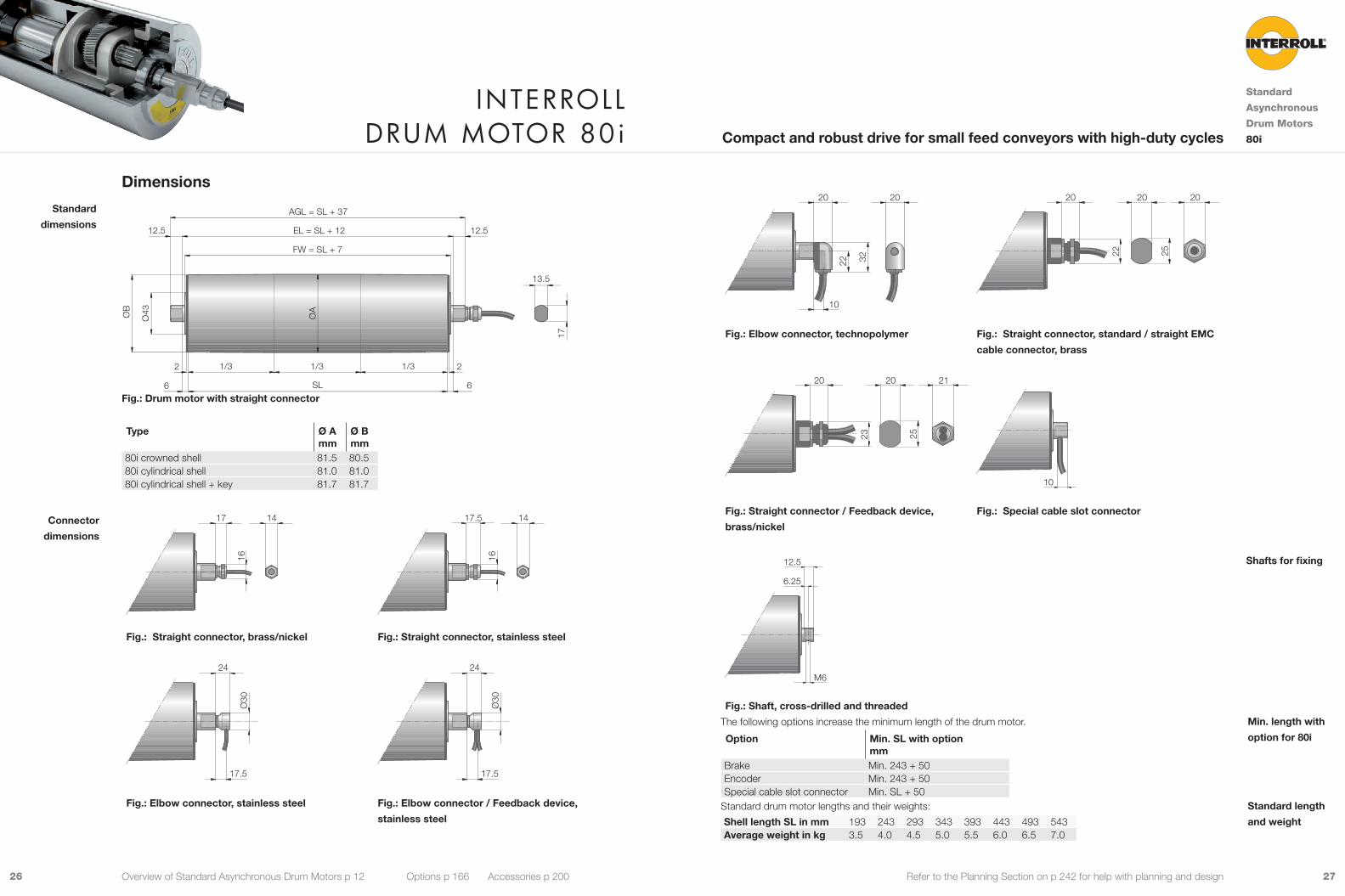
Fig.: Elbow connector, technopolymer Fig.: Straight connector, standard / straight EMC
cable connector, brass
23 25
20 20 21
10
Fig.: Straight connector / Feedback device,
brass/nickel
Fig.: Special cable slot connector
6.25
M6
12.5
Fig.: Shaft, cross-drilled and threaded
The following options increase the minimum length of the drum motor.
Option Min. SL with option mm
Brake Min. 243 + 50Encoder Min. 243 + 50Special cable slot connector Min. SL + 50
Standard drum motor lengths and their weights:
Shell length SL in mm 193 243 293 343 393 443 493 543Average weight in kg 3.5 4.0 4.5 5.0 5.5 6.0 6.5 7.0
Shafts for fixing
Min. length with
option for 80i
Standard length
and weight
Dimensions
6
2 2
12.512.5
6
1/3 1/3 1/3
13.5
EL = SL + 12
FW = SL + 7
AGL = SL + 37
SL
ØA
ØB
Ø43
17
Fig.: Drum motor with straight connector
Type Ø Amm
Ø Bmm
80i crowned shell 81.5 80.580i cylindrical shell 81.0 81.080i cylindrical shell + key 81.7 81.7
16
17 14
16
17.5 14
Fig.: Straight connector, brass/nickel Fig.: Straight connector, stainless steel
Ø30
17.5
24
Ø30
17.5
24
Fig.: Elbow connector, stainless steel Fig.: Elbow connector / Feedback device,
stainless steel
Standard
dimensions
Connector
dimensions
Interroll Drum motor 80i
Standard
Asynchronous
Drum Motors
80iCompact and robust drive for small feed conveyors with high-duty cycles
Overview of Standard Asynchronous Drum Motors p 12 Options p 166 Accessories p 200

2928 Refer to the Planning Section on p 242 for help with planning and design
Material VersionsYou can choose the following versions of drum body components and electrical connection. The versions depend
on the material of the components.
Component Version Material
Aluminium Mild steel
Stainless steel
Brass / Nickel
Shell Crowned 9 9Cylindrical 9 9Special crowns and grooves 9 9
End housing Standard 9 9Shaft cap Standard 9
With cable protection 9Regreasable 9
Electrical connector
Straight connector (for cables see p 300) 9 9Elbow connector (for cables see p 300) 9Straight gland with blue cover for screened cable
9
Straight gland with copper stocking, not for food industry
9
Straight gland with copper stocking and blue cover
9
Terminal box 9 9Please contact your Interroll customer consultant for further versions.
Options• Lagging for friction drive belts, see p 168
• Balancing, see p 189
• Food-grade oil (EU, FDA), see p 302
• Low temperature oil, see p 302
• cULus safety certifications, see p 301
• Non-horizontal mounting (more than ± 5°), see p 280
Accessories• Mounting brackets, see p 204
• Idler pulleys, see p 218 to p 230
• Conveyor rollers, see p 232
• IFI - IP55 Frequency Inverter, see p 238
Product DescriptionThe drum motor is a perfect drive station for small and medium-duty conveyor systems.
9 Light-duty conveyors
9 Packaging equipment
9 Bottle recycling
9 X-ray security scanning systems
9 Pharmaceutical handling
9 Food processing
9 Supermarket checkout conveyor
9 Dry, wet and wash-down applications
9 3-phase or 1-phase AC induction motor
9 Single-rated voltage
9 Integral motor protection
9 Techno-polymer planetary gearbox
9 Low noise
9 Lightweight
9 Maintenance-free
9 Lifetime lubricated
9 Reversible
Note: For applications without belt please use a frequency converter.
Technical DataElectrical data
Motor type Asynchronous squirrel cage motor, IEC 34 (VDE 0530)Insulation class of motor windings Class F, IEC 34 (VDE 0530)Voltage 230/400 V ±5 % (IEC 34/38)
Special voltage on requestFrequency 50/60 HzInternal shaft sealing system Double-lipped, NBRExternal shaft sealing system Deflection seal, NBRProtection rate IP66Thermal protection (see p 302) Bi-metal switchOperation mode (see p 279) S1Ambient temperature, 3-phase motor (see p 263) +5 to +40 °CAmbient temperature, 1-phase motor (see p 263) +10 to +40 °C
General technical data Max. shell length SL 1,090 mm
All data and values in this catalogue refer to 50 Hz operation.
Order InformationPlease refer to the order information at the end of the catalogue.
Applications
Characteristics
Interroll Drum motor 113s
Standard
Asynchronous
Drum Motors
113SCompact premium drive for light-duty conveyors
Overview of Standard Asynchronous Drum Motors p 12 Options p 166 Accessories p 200

3130 Refer to the Planning Section on p 242 for help with planning and design
PN Rated powernp Number of polesgs Gear stagesi Gear ratiov Rated velocity of the shellnA Rated revolutions of the shellMA Rated torque of drum motorFN Rated belt pull of drum motorTE Max. belt tensionSLmin Min. shell lengthApp. 9: Suitable for all applications. This version will ensure lowest cost and fast delivery
û: Not suitable for all applications. Please contact your Interroll customer consultantMechanical data for 1-phase motors
PN np gs i v nA MA FN TE SLmin App.
kW m/s min-1 Nm N N mm 0.060 4 3 63.00 0.122 20.6 23.8 420 2,000 240 9
49.29 0.157 26.4 18.6 328 2,000 240 944.09 0.175 29.5 16.6 294 2,000 240 938.51 0.200 33.8 14.5 256 2,000 240 930.77 0.251 42.3 11.6 205 2,000 240 926.84 0.287 48.4 10.1 179 2,000 240 923.96 0.322 54.3 9.0 160 2,000 240 9
2 15.00 0.514 86.7 6.0 105 1,500 240 911.57 0.667 112.3 4.6 81 1,500 240 910.27 0.751 126.5 4.1 72 1,500 240 98.88 0.869 146.4 3.5 62 1,500 240 97.86 0.982 165.5 3.1 55 1,500 240 9
0.080 6 2 15.00 0.352 59.3 11.6 206 1,800 275 911.57 0.456 76.9 9.0 159 1,800 275 9
0.110 4 3 63.00 0.122 20.6 43.8 772 2,000 260 949.29 0.157 26.4 34.2 604 2,000 260 944.09 0.175 29.5 30.6 541 2,000 260 938.51 0.200 33.8 26.7 472 2,000 260 930.77 0.251 42.3 21.4 377 2,000 260 926.84 0.287 48.4 18.6 329 2,000 260 923.96 0.322 54.3 16.6 294 2,000 260 9
2 15.00 0.514 86.7 11.0 194 1,500 260 911.57 0.667 112.3 8.5 149 1,500 260 910.27 0.751 126.5 7.5 133 1,500 260 98.88 0.869 146.4 6.5 115 1,500 260 97.86 0.982 165.5 5.7 101 1,500 260 9
Product RangeThe following tables give an overview of the possible motor versions. When ordering, please specify the version in
accordance with the configurator at the end of the catalogue.
Mechanical data for 3-phase motors
PN np gs i v nA MA FN TE SLmin App.
kW m/s min-1 Nm N N mm 0.040 8 3 63.00 0.068 11.4 28.6 505 2,700 260 9
49.29 0.087 14.6 22.4 395 2,700 260 938.51 0.111 18.7 17.5 309 2,700 260 9
0.110 6 2 15.00 0.342 57.7 16.4 289 1,500 275 94 3 63.00 0.129 21.7 41.6 734 2,000 240 9
49.29 0.164 27.7 32.5 574 2,000 240 944.09 0.184 31.0 29.1 514 2,000 240 938.51 0.210 35.4 25.4 449 2,000 240 930.77 0.263 44.4 20.3 359 2,000 240 926.84 0.302 50.9 17.7 313 2,000 240 923.96 0.338 57.0 15.8 279 2,000 240 9
2 15.00 0.540 91.0 10.4 184 1,500 240 911.57 0.700 118.0 8.0 142 1,500 240 910.27 0.788 132.9 7.1 126 1,500 240 98.88 0.912 153.8 6.2 109 1,500 240 97.86 1.031 173.7 5.5 96 1,500 240 9
0.160 4 3 44.09 0.182 30.6 42.7 754 2,000 260 90.180 4 3 38.51 0.209 35.2 41.9 740 2,000 275 9
30.77 0.261 44.0 33.5 591 2,000 275 926.84 0.300 50.5 29.2 516 2,000 275 923.96 0.336 56.6 26.1 461 2,000 275 9
2 15.00 0.536 90.3 17.2 303 1,500 275 911.57 0.695 117.1 13.3 234 1,500 275 910.27 0.783 131.9 11.8 208 1,500 275 98.88 0.906 152.6 10.2 180 1,500 275 97.86 1.023 172.5 9.0 159 1,500 275 9
0.330 2 3 44.09 0.377 63.5 42.7 754 2,000 275 938.51 0.431 72.7 37.3 659 2,000 275 930.77 0.540 91.0 29.8 526 2,000 275 926.84 0.619 104.3 26.0 459 2,000 275 923.96 0.693 116.9 23.2 410 2,000 275 9
2 15.00 1.107 186.7 15.3 270 1,500 275 911.57 1.436 242.0 11.8 208 1,500 275 910.27 1.617 272.6 10.5 185 1,500 275 98.88 1.871 315.4 9.1 160 1,500 275 97.86 2.114 356.4 8.0 141 1,500 275 9
Motor versions
Interroll Drum motor 113s
Standard
Asynchronous
Drum Motors
113SCompact premium drive for light-duty conveyors
Overview of Standard Asynchronous Drum Motors p 12 Options p 166 Accessories p 200

3332 Refer to the Planning Section on p 242 for help with planning and design
Cable SpecificationsAvailable cables for connectors (see also p 300):
• Standard, screened
• Standard, unscreened
• Halogen-free, screened
• Halogen-free, unscreened
Available length: 1 / 3 / 5 m
Note: Only one voltage is available with screened and halogen-free cables.
Connection DiagramsFor connection diagrams, see Planning Section on p 304.
Electrical data for 3-phase motors
PN np UN IN cos φ η JR IS/IN MS/MN MP/MN MB/MN RM USH delta USH star
kW V A kgcm2 Ω V DC V DC0.040 8 230 0.64 0.58 0.27 3.9 1.5 1.59 1.49 1.59 187.5 35 -
400 0.37 0.58 0.27 3.9 1.5 1.59 1.49 1.59 187.5 - 600.110 6 230 1.05 0.67 0.39 4.0 2.2 2.24 2.24 2.35 30.0 11 -
400 0.62 0.62 0.41 4.0 2.0 3.14 3.14 3.35 92.0 - 534 230 0.80 0.73 0.47 2.3 3.6 3.38 3.38 3.39 84.0 25 -
400 0.45 0.75 0.47 2.3 3.6 3.41 3.41 3.42 84.0 - 430.160 4 230 0.98 0.76 0.54 3.3 4.0 3.22 3.22 3.33 59.2 22 -
400 0.57 0.75 0.54 3.3 4.0 3.25 3.25 3.35 59.2 - 380.180 4 230 1.00 0.77 0.59 4.0 4.4 3.54 3.54 3.74 45.5 18 -
400 0.62 0.76 0.55 4.0 4.4 3.60 3.60 3.79 45.5 - 320.330 2 230 1.74 0.76 0.68 3.3 4.5 3.57 2.62 3.57 21.5 14 -
400 0.93 0.76 0.68 3.3 4.5 3.57 2.62 3.57 21.5 - 23
Electrical data for 1-phase motors
PN np UN IN cos φ η JR IS/IN MS/MN MP/MN MB/MN RM USH ~ Cr
kW V A kgcm2 Ω V DC µF0.060 4 230 0.74 0.98 0.36 2.3 2.6 1.29 1.29 2.60 63.5 35 40.080 6 230 1.35 0.99 0.26 4.0 1.9 0.70 0.70 1.65 45.9 46 80.110 4 230 1.13 0.88 0.48 3.2 2.9 1.06 1.06 2.31 32.5 24 6
PN Rated powernp Number of polesUN Rated voltageIN Rated currentcos φ Power factorη EfficiencyJR Rotor moment of inertiaIS/IN Ratio of starting current to rated currentMS/MN Ratio of starting torque to rated torqueMP/MN Ratio of pull-up torque to rated torqueMB/MN Ratio of break-down torque to rated torqueRM Phase resistanceUSH delta Preheating voltage in delta connectionUSH star Preheating voltage in star connectionUSH ∿ Preheating voltage in single phaseCr Capacitor size
Interroll Drum motor 113s
Standard
Asynchronous
Drum Motors
113SCompact premium drive for light-duty conveyors
Overview of Standard Asynchronous Drum Motors p 12 Options p 166 Accessories p 200
3534 Refer to the Planning Section on p 242 for help with planning and design
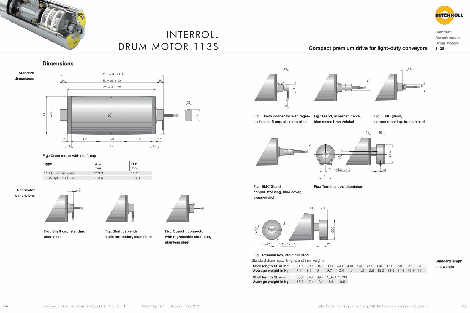
25
18
Ø30
27
17
14.5
Fig.: Elbow connector with regre-
asable shaft cap, stainless steel
Fig.: Gland, screened cable,
blue cover, brass/nickel
Fig.: EMC gland,
copper stocking, brass/nickel
27
65
17 22
46
Ø95
14
M20 x 1.5
18
Fig.: EMC Gland,
copper stocking, blue cover,
brass/nickel
Fig.: Terminal box, aluminium
47
20°
14
M20 x 1.5
18
25
43
Ø99
Fig.: Terminal box, stainless steel
Standard drum motor lengths and their weights:
Shell length SL in mm 240 290 340 390 440 490 540 590 640 690 740 790 840Average weight in kg 7.6 8.3 9 9.7 10.4 11.1 11.8 12.5 13.2 13.9 14.6 15.3 16
Shell length SL in mm 890 940 990 1,040 1,090Average weight in kg 16.7 17.4 18.1 18.8 19.5
Standard length
and weight
Dimensions
21
EL = SL + 28
AGL = SL + 68
Ø45 ØA
SL
FW = SL + 22
ØB 35
1/3 1/3 1/3
14
20 20
11
14
11
Fig.: Drum motor with shaft cap
Type Ø Amm
Ø Bmm
113S crowned shell 113.3 112.4113S cylindrical shell 113.0 113.0
2.2 20 ?
?
Fig.: Shaft cap, standard,
aluminium
Fig.: Shaft cap with
cable protection, aluminium
Fig.: Straight connector
with regreasable shaft cap,
stainless steel
Standard
dimensions
Connector
dimensions
Interroll Drum motor 113s
Standard
Asynchronous
Drum Motors
113SCompact premium drive for light-duty conveyors
Overview of Standard Asynchronous Drum Motors p 12 Options p 166 Accessories p 200

3736 Refer to the Planning Section on p 242 for help with planning and design
Material VersionsYou can choose the following versions of drum body components and electrical connection. The versions depend
on the material of the components.
Component Version Material
Aluminium Mild steel
Stainless steel
Brass / Nickel
Techno-polymer
Shell Crowned 9 9Cylindrical 9 9Cylindrical + key, for using sprockets 9 9Special crowns and grooves 9 9
End housing Standard 9 9With V-grooves 9With O-grooves 9With chain sprockets 9 9
Shaft Standard 9 9Cross-drilled thread, M8 9 9
External seal Galvanised labyrinth 9Labyrinth 9Labyrinth with FPM 9
Electrical connector
Straight connector (for cables see p 300) 9 9 9
Elbow connector (for cables see p 300) 9 9Terminal box 9 9 9
Please contact your Interroll customer consultant for further versions.
Options• Lagging for friction drive belts, see p 168
• Lagging for plastic modular belts, see p 174
• Lagging for positive drive solid homogeneous
belts, see p 178
• Sprockets for plastic modular belts, see p 180
• Backstops, see p 188
• Balancing, see p 189
• Electromagnetic brakes, see p 190
• Rectifiers, see p 194
• Encoders, see p 196
• Food-grade oil (EU, FDA), see p 302
• Low temperature oil, see p 302
• cULus safety certifications, see p 301
• 2-speed motors, see p 294
Note: Combination of encoder and electromagnetic brake is not possible.
Accessories• Mounting brackets, see p 204
• Idler pulleys, see p 218 to p 230
• Conveyor rollers, see p 232
• IFI - IP55 Frequency Inverter, see p 238
Product DescriptionThis drum motor has been developed especially for applications requiring a strong drive.
9 Small conveyors with high-duty cycles
9 Airport check-in conveyors
9 Packaging equipment
9 Dynamic weighing equipment
9 Metal detectors
9 Pharmaceutical handling
9 Food processing
9 Steel or plastic modular belt applications
9 Dry, wet and wash down-applications
9 Salt-water-resistant aluminium bearing housings
9 3-phase AC induction motor
9 Dual voltage
9 Integral motor protection
9 Steel-hardened helical spur gear
9 Low noise
9 Maintenance-free
9 Lifetime lubricated
9 Reversible
9 Reinforced shaft for SL above 850 mm
Note: For applications with positive drive belts please use a frequency converter or cool-running drum motor.
Technical DataElectrical data
Motor type Asynchronous squirrel cage motor, IEC 34 (VDE 0530)Insulation class of motor windings Class F, IEC 34 (VDE 0530)Voltage 230/400 V ±5 % (IEC 34/38)
Special voltage on requestFrequency 50/60 HzInternal shaft sealing system Double-lipped, FPM or NBRProtection rate IP66Thermal protection (see p 302) Bi-metal switchOperation mode (see p 279) S1Ambient temperature, 3-phase motor (see p 263) +5 to +40 °C
General technical data Max. shell length SL 1,200 mm
All data and values in this catalogue refer to 50 Hz operation.
Order InformationPlease refer to the order information at the end of the catalogue.
Applications
Characteristics
Interroll Drum motor 113i
Standard
Asynchronous
Drum Motors
113iPower-packed drive for small conveyors with high-duty cycles
Overview of Standard Asynchronous Drum Motors p 12 Options p 166 Accessories p 200

3938 Refer to the Planning Section on p 242 for help with planning and design
PN np gs i v nA MA FN TE SLmin App.
kW m/s min-1 Nm N N mm 0.225 2 3 43.49 0.386 64.9 31.1 548 6,550 250 9
31.96 0.525 88.3 22.9 403 6,550 250 928.17 0.595 100.1 20.2 355 6,550 250 924.00 0.699 117.5 17.2 303 6,550 250 920.71 0.810 136.2 14.8 261 6,550 250 9
2 15.17 1.105 186.0 11.1 195 6,550 250 912.92 1.297 218.3 9.4 166 6,550 250 911.15 1.504 253.0 8.1 143 6,550 250 9
0.300 4 3 43.49 0.188 31.6 85.1 1,500 6,550 300 931.96 0.256 43.1 62.6 1,103 6,550 300 928.17 0.290 48.8 55.2 972 6,550 300 924.00 0.341 57.3 47.0 828 6,550 300 920.71 0.395 66.5 40.5 714 6,550 300 9
2 15.17 0.539 90.7 30.3 534 6,550 300 912.92 0.633 106.5 25.8 455 6,550 300 911.15 0.733 123.4 22.3 392 6,550 300 9
0.370 4 3 24.00 0.322 54.2 61.4 1,083 6,550 300 920.71 0.373 62.8 53.0 934 6,550 300 9
2 15.17 0.510 85.8 39.6 698 6,550 300 û12.92 0.598 100.7 33.8 595 6,550 300 911.15 0.693 116.7 29.1 513 6,550 300 9
2 3 43.49 0.387 65.2 51.2 901 6,550 300 931.96 0.527 88.7 37.6 663 6,550 300 928.17 0.598 100.6 33.1 584 6,550 300 924.00 0.702 118.1 28.2 498 6,550 300 920.71 0.814 136.9 24.4 429 6,550 300 9
2 15.17 1.111 186.9 18.2 321 6,550 300 912.92 1.304 219.4 15.5 273 6,550 300 911.15 1.511 254.3 13.4 236 6,550 300 9
PN Rated powernp Number of polesgs Gear stagesi Gear ratiov Rated velocity of the shellnA Rated revolutions of the shellMA Rated torque of drum motorFN Rated belt pull of drum motorTE Max. belt tensionSLmin Min. shell lengthApp. 9: Suitable for all applications. This version will ensure lowest cost and fast delivery
û: Not suitable for all applications. Please contact your Interroll customer consultant
Product RangeThe following tables give an overview of the possible motor versions. When ordering, please specify the version in
accordance with the configurator at the end of the catalogue.
Mechanical data for 3-phase motors
PN np gs i v nA MA FN TE SLmin App.
kW m/s min-1 Nm N N mm 0.035 12 3 43.49 0.048 8.1 38.9 685 6,550 250 û
37.05 0.057 9.5 33.1 584 6,550 250 û31.96 0.066 11.0 28.6 504 6,550 250 û
0.070 12 3 43.49 0.048 8.1 77.4 1,363 6,550 300 û37.05 0.057 9.5 65.9 1,161 6,550 300 û31.96 0.066 11.0 56.9 1,002 6,550 300 û
0.080 8 3 43.49 0.093 15.6 45.8 808 6,550 250 937.05 0.109 18.4 39.1 688 6,550 250 928.17 0.143 24.1 29.7 523 6,550 250 920.71 0.195 32.8 21.8 385 6,550 250 9
2 15.17 0.266 44.8 16.3 288 6,550 250 911.15 0.362 61.0 12.0 211 6,550 250 9
0.100 6 3 43.49 0.118 19.9 45.0 793 6,550 250 937.05 0.139 23.3 38.4 676 6,550 250 928.17 0.183 30.7 29.2 514 6,550 250 920.71 0.248 41.8 21.4 378 6,550 250 9
2 15.17 0.339 57.0 16.0 282 6,550 250 90.150 8 3 43.49 0.093 15.6 86.4 1,522 6,550 300 9
37.05 0.109 18.3 73.6 1,296 6,550 300 931.96 0.126 21.2 63.5 1,119 6,550 300 9
4 3 43.49 0.185 31.0 43.4 764 6,550 250 931.96 0.251 42.2 31.9 562 6,550 250 928.17 0.285 47.9 28.1 495 6,550 250 924.00 0.334 56.2 23.9 422 6,550 250 920.71 0.388 65.2 20.7 364 6,550 250 9
2 15.17 0.529 89.0 15.4 272 6,550 250 912.92 0.621 104.5 13.2 232 6,550 250 911.15 0.720 121.1 11.4 200 6,550 250 9
0.180 6 3 43.49 0.125 21.0 76.9 1,356 6,550 300 937.05 0.147 24.7 65.6 1,155 6,550 300 928.17 0.193 32.5 49.8 878 6,550 300 920.71 0.263 44.2 36.6 646 6,550 300 9
2 15.17 0.359 60.3 27.4 483 6,550 300 911.15 0.488 82.1 20.1 355 6,550 300 9
Motor versions
Interroll Drum motor 113i
Standard
Asynchronous
Drum Motors
113iPower-packed drive for small conveyors with high-duty cycles
Overview of Standard Asynchronous Drum Motors p 12 Options p 166 Accessories p 200

4140 Refer to the Planning Section on p 242 for help with planning and design
Cable SpecificationsAvailable cables for connectors (see also p 300):
• Standard, screened
• Standard, unscreened
• Halogen-free, screened
• Halogen-free, unscreened
Available length: 1 / 3 / 5 / 10 m
Connection DiagramsFor connection diagrams, see Planning Section on p 307.
Electrical data for 3-phase motors
PN np UN IN cos φ η JR IS/IN MS/MN MP/MN MB/MN RM USH delta USH star
kW V A kgcm2 Ω V DC V DC0.035 12 230 0.71 0.60 0.21 3.3 2.4 1.10 1.10 1.46 208.0 44 -
400 0.41 0.60 0.21 3.3 2.4 1.10 1.10 1.46 208.0 - 770.070 12 230 1.07 0.60 0.27 5.7 2.0 1.00 1.00 1.30 128.0 41 -
400 0.62 0.60 0.27 5.7 2.0 1.00 1.00 1.30 128.0 - 710.080 8 230 0.69 0.60 0.48 3.3 2.2 1.40 1.40 1.60 164.0 34 -
400 0.40 0.60 0.48 3.3 2.2 1.40 1.40 1.60 164.0 - 590.100 6 230 0.80 0.66 0.47 3.3 2.1 1.80 1.80 2.00 111.4 29 -
400 0.46 0.66 0.47 3.3 2.1 1.80 1.80 2.00 111.4 - 510.150 8 230 1.18 0.62 0.51 5.7 2.2 1.35 1.35 1.50 89.0 33 -
400 0.68 0.62 0.51 5.7 2.2 1.35 1.35 1.50 89.0 - 564 230 0.94 0.71 0.56 2.1 3.2 1.85 1.85 2.15 71.0 24 -
400 0.54 0.71 0.56 2.1 3.2 1.85 1.85 2.15 71.0 - 410.180 6 230 1.39 0.62 0.52 5.7 2.4 2.80 2.80 3.00 42.8 18 -
400 0.80 0.62 0.52 5.7 2.4 2.80 2.80 3.00 42.8 - 320.225 2 230 1.21 0.71 0.65 1.4 4.6 3.50 3.50 3.70 29.6 13 -
400 0.70 0.71 0.65 1.4 4.6 3.50 3.50 3.70 29.6 - 220.300 4 230 1.58 0.79 0.60 3.8 3.2 1.70 1.70 1.90 41.0 26 -
400 0.91 0.79 0.60 3.8 3.2 1.70 1.70 1.90 41.0 - 440.370 4 230 1.91 0.79 0.62 3.8 3.2 2.40 2.20 2.30 26.4 20 -
400 1.10 0.79 0.62 3.8 3.2 2.40 2.20 2.30 26.4 - 342 230 1.91 0.79 0.62 2.4 6.1 3.65 3.65 3.90 16.5 12 -
400 1.10 0.79 0.62 2.4 6.1 3.65 3.65 3.90 16.5 - 22
PN Rated powernp Number of polesUN Rated voltageIN Rated currentcos φ Power factorη EfficiencyJR Rotor moment of inertiaIS/IN Ratio of starting current to rated currentMS/MN Ratio of starting torque to rated torqueMP/MN Ratio of pull-up torque to rated torqueMB/MN Ratio of break-down torque to rated torqueRM Phase resistanceUSH delta Preheating voltage in delta connectionUSH star Preheating voltage in star connection
Interroll Drum motor 113i
Standard
Asynchronous
Drum Motors
113iPower-packed drive for small conveyors with high-duty cycles
Overview of Standard Asynchronous Drum Motors p 12 Options p 166 Accessories p 200
4342 Refer to the Planning Section on p 242 for help with planning and design
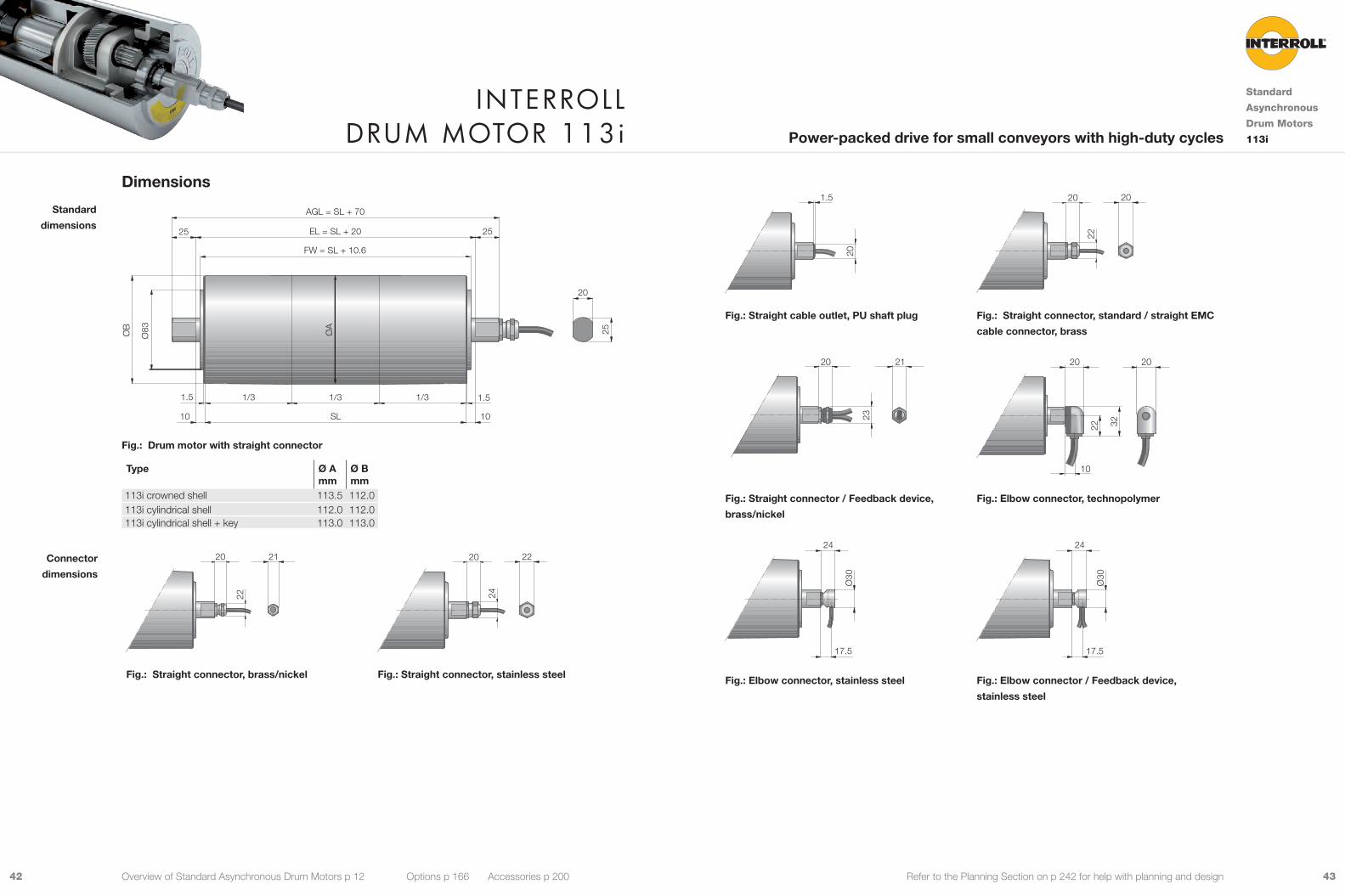
Dimensions
ØB
ØA
Ø83
FW = SL + 10.6
EL = SL + 2025 25
25
20
1010
1.51.5
SL
AGL = SL + 70
1/3 1/3 1/3
Fig.: Drum motor with straight connector
Type Ø Amm
Ø Bmm
113i crowned shell 113.5 112.0113i cylindrical shell 112.0 112.0113i cylindrical shell + key 113.0 113.0
22
20 21
24
20 22
Fig.: Straight connector, brass/nickel Fig.: Straight connector, stainless steel
Standard
dimensions
Connector
dimensions
Interroll Drum motor 113i
Standard
Asynchronous
Drum Motors
113iPower-packed drive for small conveyors with high-duty cycles
Overview of Standard Asynchronous Drum Motors p 12 Options p 166 Accessories p 200
20
1.5
22
20 20
Fig.: Straight cable outlet, PU shaft plug Fig.: Straight connector, standard / straight EMC
cable connector, brass
23
20 21
22 32
10
20 20
Fig.: Straight connector / Feedback device,
brass/nickel
Fig.: Elbow connector, technopolymer
Ø30
17.5
24
Ø30
17.5
24
Fig.: Elbow connector, stainless steel Fig.: Elbow connector / Feedback device,
stainless steel

4544 Refer to the Planning Section on p 242 for help with planning and design
47
20° 25
4323
Ø99
14
M20 x 1.5
50
30° 39
72
Ø10
5
M20 x 1.5
23
Fig.: Terminal box, stainless steel Fig.: Terminal box, technopolymer
65
17 22
4623
Ø95
14
M20 x 1.56.5
Fig.: Terminal box, aluminium Fig.: Special cable slot connector
25
M8
12.5
Fig.: Shaft, cross-drilled and threaded
Shafts for fixing
Interroll Drum motor 113i
Standard
Asynchronous
Drum Motors
113iPower-packed drive for small conveyors with high-duty cycles
Overview of Standard Asynchronous Drum Motors p 12 Options p 166 Accessories p 200
The following options increase the minimum length of the drum motor.
Option Min. SL with option mm
Brake Min. SL + 50Encoder Min. SL + 50Special cable slot connector Min. SL + 50
Standard drum motor lengths and their weights:
Shell length SL in mm 250 300 350 400 450 500 550 600 650 700 750 800 850Average weight in kg 8.5 9.15 9.8 10.5 11.1 11.75 12.4 13.05 13.7 14.35 15.0 15.65 16.3
Min. length with
option
Standard length
and weight
4746 Refer to the Planning Section on p 242 for help with planning and design
Material VersionsYou can choose the following versions of drum body components and electrical connection. The versions depend
on the material of the components.
Component Version Material
Aluminium Mild steel
Stainless steel
Brass / Nickel
Techno-polymer
Shell Crowned 9 9Cylindrical 9 9Cylindrical + key, for using sprockets 9 9Special crowns and grooves 9 9
End housing Standard 9 9With V-grooves 9With O-grooves 9With chain sprockets 9 9
Shaft Standard 9 9Cross-drilled thread, M8 9 9
External seal Galvanised labyrinth 9Labyrinth 9Labyrinth with FPM 9
Electrical connector
Straight connector (for cables see p 300) 9 9 9
Elbow connector (for cables see p 300) 9 9Terminal box 9 9 9
Please contact your Interroll customer consultant for further versions.
Options• Lagging for friction drive belts, see p 168
• Lagging for plastic modular belts, see p 174
• Lagging for positive drive solid homogeneous
belts, see p 178
• Sprockets for plastic modular belts, see p 180
• Backstops, see p 188
• Balancing, see p 189
• Electromagnetic brakes, see p 190
• Rectifiers, see p 194
• Encoders, see p 196
• Food-grade oil (EU, FDA), see p 302
• Low temperature oil, see p 302
• cULus safety certifications, see p 301
• 2-speed motors, see p 294
Note: Combination of encoder and electromagnetic brake is not possible.
Accessories• Mounting brackets, see p 204
• Idler pulleys, see p 218 to p 230
• Conveyor rollers, see p 232
• IFI - IP55 Frequency Inverter, see p 238
Product DescriptionThe drum motor is a real all-round component because of its wide power and speed range.
9 Conveyors with high-duty cycles
9 Transport conveyors
9 Logistics applications
9 Airport check-in conveyors
9 Mobile conveyors
9 Food processing
9 Steel or plastic modular belt applications
9 Dry, wet and wash-down applications
9 Salt-water-resistant aluminium bearing housings
9 3-phase AC induction motor
9 Dual voltage
9 Integral motor protection
9 Steel-hardened helical spur gear
9 Low noise
9 Maintenance-free
9 Lifetime lubricated
9 Reversible
9 Reinforced shaft for SL above 900 mm
Note: For applications with positive drive belts please use a frequency converter or cool-running drum motor.
Technical DataElectrical data
Motor type Asynchronous squirrel cage motor, IEC 34 (VDE 0530)Insulation class of motor windings Class F, IEC 34 (VDE 0530)Voltage 230/400 V ±5 % (IEC 34/38)
Special voltage on requestFrequency 50/60 HzInternal shaft sealing system Double-lipped, FPM or NBRProtection rate IP66Thermal protection (see p 302) Bi-metal switchOperation mode (see p 279) S1Ambient temperature, 3-phase motor (see p 263) +5 to +40 °C
General technical data Max. shell length SL 1,600 mm
All data and values in this catalogue refer to 50 Hz operation.
Order InformationPlease refer to the order information at the end of the catalogue.
Applications
Characteristics
Interroll Drum motor 138i
Standard
Asynchronous
Drum Motors
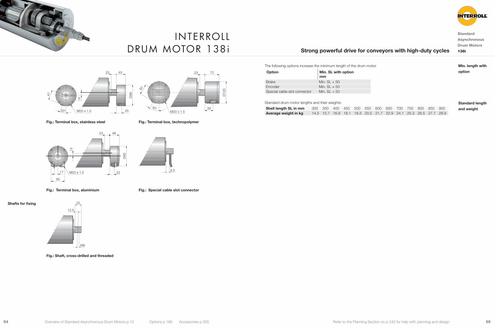
138iStrong powerful drive for conveyors with high-duty cycles
Overview of Standard Asynchronous Drum Motors p 12 Options p 166 Accessories p 200

4948 Refer to the Planning Section on p 242 for help with planning and design
PN np gs i v nA MA FN TE SLmin App.
kW m/s min-1 Nm N N mm 0.550 2 3 72.55 0.282 39.0 122.9 1,780 8,300 300 9
61.85 0.330 45.7 105.7 1,532 8,300 300 949.64 0.411 56.9 85.6 1,240 8,300 300 940.91 0.499 69.1 71.1 1,031 8,300 300 934.00 0.601 83.1 59.1 856 8,300 300 925.39 0.804 111.3 44.3 641 8,300 300 9
2 20.22 1.010 139.7 35.6 516 8,300 300 916.67 1.225 169.6 29.6 428 8,300 300 912.44 1.641 227.1 22.1 321 8,300 300 910.00 2.042 282.6 17.8 258 8,300 300 9
0.750 4 3 34.00 0.294 40.6 164.9 2,390 8,300 350 930.55 0.327 45.2 148.1 2,147 8,300 350 925.39 0.393 54.4 123.5 1,790 8,300 350 9
2 20.22 0.493 68.3 99.3 1,438 8,300 350 916.67 0.599 82.9 82.5 1,195 8,300 350 912.44 0.802 111.0 61.8 895 8,300 350 910.00 0.998 138.1 49.6 719 8,300 350 9
1.000 2 3 49.64 0.404 55.9 158.2 2,293 8,300 350 940.91 0.490 67.8 131.5 1,906 8,300 350 934.00 0.590 81.6 109.3 1,584 8,300 350 925.39 0.790 109.3 81.9 1,186 8,300 350 9
2 20.22 0.992 137.2 65.8 953 8,300 350 916.67 1.203 166.5 54.7 792 8,300 350 912.44 1.611 223.0 40.9 593 8,300 350 910.00 2.005 277.5 32.9 477 8,300 350 9
PN Rated powernp Number of polesgs Gear stagesi Gear ratiov Rated velocity of the shellnA Rated revolutions of the shellMA Rated torque of drum motorFN Rated belt pull of drum motorTE Max. belt tensionSLmin Min. shell lengthApp. 9: Suitable for all applications. This version will ensure lowest cost and fast delivery
û: Not suitable for all applications. Please contact your Interroll customer consultant
Product RangeThe following tables give an overview of the possible motor versions. When ordering, please specify the version in
accordance with the configurator at the end of the catalogue.
Mechanical data for 3-phase motors
PN np gs i v nA MA FN TE SLmin App.
kW m/s min-1 Nm N N mm 0.090 12 3 72.55 0.041 5.7 136.7 1,981 8,300 300 û
49.64 0.060 8.4 95.2 1,380 8,300 300 û40.91 0.073 10.1 79.1 1,147 8,300 300 û30.55 0.098 13.6 59.1 856 8,300 300 û
0.180 8 3 72.55 0.068 9.4 165.8 2,403 8,300 300 949.64 0.100 13.8 115.5 1,673 8,300 300 940.91 0.121 16.7 96.0 1,391 8,300 300 930.55 0.162 22.4 71.6 1,038 8,300 300 925.39 0.195 26.9 59.7 866 8,300 300 9
2 20.22 0.244 33.8 48.0 696 8,300 300 916.67 0.297 41.0 39.9 578 8,300 300 9
0.250 6 3 72.55 0.091 12.5 173.1 2,508 8,300 300 949.64 0.133 18.3 120.5 1,747 8,300 300 940.91 0.161 22.2 100.2 1,452 8,300 300 934.00 0.193 26.8 83.2 1,206 8,300 300 930.55 0.215 29.8 74.8 1,084 8,300 300 925.39 0.259 35.8 62.3 904 8,300 300 9
2 20.22 0.325 45.0 50.1 726 8,300 300 916.67 0.395 54.6 41.6 603 8,300 300 912.44 0.528 73.1 31.2 452 8,300 300 9
0.370 4 3 72.55 0.134 18.5 174.4 2,527 8,300 300 961.85 0.157 21.7 150.1 2,175 8,300 300 949.64 0.195 27.0 121.4 1,760 8,300 300 940.91 0.237 32.8 100.9 1,463 8,300 300 934.00 0.285 39.4 83.9 1,216 8,300 300 930.55 0.317 43.9 75.4 1,092 8,300 300 925.39 0.381 52.8 62.8 910 8,300 300 9
2 20.22 0.479 66.3 50.5 732 8,300 300 916.67 0.581 80.4 42.0 608 8,300 300 912.44 0.778 107.7 31.4 455 8,300 300 910.00 0.968 134.0 25.3 366 8,300 300 9
Motor versions
Interroll Drum motor 138i
Standard
Asynchronous
Drum Motors
138iStrong powerful drive for conveyors with high-duty cycles
Overview of Standard Asynchronous Drum Motors p 12 Options p 166 Accessories p 200

5150 Refer to the Planning Section on p 242 for help with planning and design
Cable SpecificationsAvailable cables for connectors (see also p 300):
• Standard, screened
• Standard, unscreened
• Halogen-free, screened
• Halogen-free, unscreened
Available length: 1 / 3 / 5 / 10 m
Connection DiagramsFor connection diagrams, see Planning Section on p 307.
Electrical data for 3-phase motors
PN np UN IN cos φ η JR IS/IN MS/MN MP/MN MB/MN RM USH delta USH star
kW V A kgcm2 Ω V DC V DC0.090 12 230 1.14 0.40 0.49 9.3 3.0 1.15 1.15 1.68 92.0 21 -
400 0.66 0.40 0.49 9.3 3.0 1.15 1.15 1.68 92.0 - 360.180 8 230 1.21 0.64 0.58 9.3 2.6 1.10 1.10 1.55 64.0 25 -
400 0.70 0.64 0.58 9.3 2.6 1.10 1.10 1.55 64.0 - 430.250 6 230 1.30 0.72 0.67 9.3 3.0 1.35 1.35 1.75 44.0 21 -
400 0.75 0.72 0.67 9.3 3.0 1.35 1.35 1.75 44.0 - 360.370 4 230 1.68 0.79 0.70 5.6 3.3 1.55 1.55 1.95 26.5 18 -
400 0.97 0.79 0.70 5.6 3.3 1.55 1.55 1.95 26.5 - 300.550 2 230 2.25 0.80 0.76 3.5 5.5 3.20 3.20 3.65 11.4 10 -
400 1.30 0.80 0.76 3.5 5.5 3.20 3.20 3.65 11.4 - 180.750 4 230 3.29 0.80 0.71 9.9 3.4 2.10 2.10 2.45 9.7 13 -
400 1.90 0.80 0.71 9.9 3.4 2.10 2.10 2.45 9.7 - 221.000 2 230 4.16 0.80 0.75 6.2 5.4 3.40 3.40 3.95 5.4 9 -
400 2.40 0.80 0.75 6.2 5.4 3.40 3.40 3.95 5.4 - 16
PN Rated powernp Number of polesUN Rated voltageIN Rated currentcos φ Power factorη EfficiencyJR Rotor moment of inertiaIS/IN Ratio of starting current to rated currentMS/MN Ratio of starting torque to rated torqueMP/MN Ratio of pull-up torque to rated torqueMB/MN Ratio of break-down torque to rated torqueRM Phase resistanceUSH delta Preheating voltage in delta connectionUSH star Preheating voltage in star connection
Interroll Drum motor 138i
Standard
Asynchronous
Drum Motors
138iStrong powerful drive for conveyors with high-duty cycles
Overview of Standard Asynchronous Drum Motors p 12 Options p 166 Accessories p 200
5352 Refer to the Planning Section on p 242 for help with planning and design
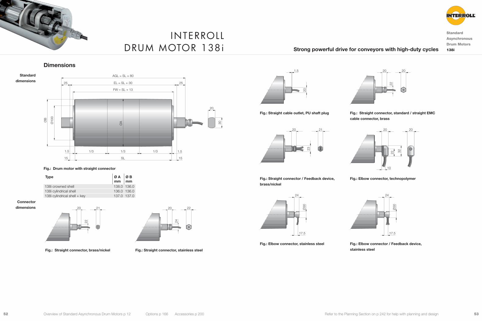
Dimensions
ØB
ØAØ10
0
FW = SL + 13
EL = SL + 3025 25
30
20
1515
1.51.5
SL
AGL = SL + 80
1/3 1/3 1/3
Fig.: Drum motor with straight connector
Type Ø Amm
Ø Bmm
138i crowned shell 138.0 136.0138i cylindrical shell 136.0 136.0138i cylindrical shell + key 137.0 137.0
22
20 21
24
20 22
Fig.: Straight connector, brass/nickel Fig.: Straight connector, stainless steel
Standard
dimensions
Connector
dimensions
20
1.5
22
20 20
Fig.: Straight cable outlet, PU shaft plug Fig.: Straight connector, standard / straight EMC
cable connector, brass
23
20 21
22 32
10
20 20
Fig.: Straight connector / Feedback device,
brass/nickel
Fig.: Elbow connector, technopolymer
Ø30
17.5
24
Ø30
17.5
24
Fig.: Elbow connector, stainless steel Fig.: Elbow connector / Feedback device,
stainless steel
Interroll Drum motor 138i
Standard
Asynchronous
Drum Motors
138iStrong powerful drive for conveyors with high-duty cycles
Overview of Standard Asynchronous Drum Motors p 12 Options p 166 Accessories p 200
5554 Refer to the Planning Section on p 242 for help with planning and design
47
20° 25
4323
Ø99
14
M20 x 1.5
50
30° 39
72
Ø10
5
M20 x 1.5
23
Fig.: Terminal box, stainless steel Fig.: Terminal box, technopolymer
65
17 22
4623
Ø95
14
M20 x 1.56.5
Fig.: Terminal box, aluminium Fig.: Special cable slot connector
25
M8
12.5
Fig.: Shaft, cross-drilled and threaded
Shafts for fixing
Interroll Drum motor 138i
Standard
Asynchronous
Drum Motors
138iStrong powerful drive for conveyors with high-duty cycles
Overview of Standard Asynchronous Drum Motors p 12 Options p 166 Accessories p 200
The following options increase the minimum length of the drum motor.
Option Min. SL with option mm
Brake Min. SL + 50Encoder Min. SL + 50Special cable slot connector Min. SL + 50
Standard drum motor lengths and their weights:
Shell length SL in mm 300 350 400 450 500 550 600 650 700 750 800 850 900Average weight in kg 14.5 15.7 16.9 18.1 19.3 20.5 21.7 22.9 24.1 25.3 26.5 27.7 28.9
Min. length with
option
Standard length
and weight

5756 Refer to the Planning Section on p 242 for help with planning and design
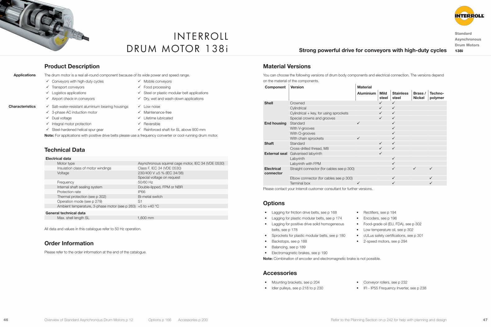
Material VersionsYou can choose the following versions of drum body components and electrical connection. The versions depend
on the material of the components.
Component Version Material
Aluminium Mild steel
Stainless steel
Brass / Nickel
Techno-polymer
Shell Crowned 9 9Cylindrical 9 9Cylindrical + key, for using sprockets 9 9Special crowns and grooves 9 9
End housing Standard 9 9With V-grooves 9With O-grooves 9With chain sprockets 9 9
Shaft Standard 9 9Cross-drilled thread, M10 9 9
External seal Galvanised labyrinth 9Labyrinth 9Labyrinth with FPM 9
Electrical connector
Straight connector (for cables see p 300) 9 9 9Elbow connector (for cables see p 300) 9 9Terminal box 9 9 9
Please contact your Interroll customer consultant for further versions.
Options• Lagging for friction drive belts, see p 168
• Lagging for plastic modular belts, see p 174
• Lagging for positive drive solid homogeneous
belts, see p 178
• Sprockets for plastic modular belts, see p 180
• Backstops, see p 188
• Balancing, see p 189
• Electromagnetic brakes, see p 190
• Rectifiers, see p 194
• Encoders, see p 196
• Food-grade oil (EU, FDA), see p 302
• Low temperature oil, see p 302
• cULus safety certifications, see p 301
• 2-speed motors, see p 294
Note: Combination of encoder and electromagnetic brake is not possible.
Accessories• Mounting brackets, see p 204
• Idler pulleys, see p 218 to p 230
• Conveyor rollers, see p 232
• IFI - IP55 Frequency Inverter, see p 238
Product DescriptionThe drum motor is outstandingly robust with a strong torque and can take a high radial load.
9 Conveyors with high-duty cycles
9 Logistics applications
9 Airport and postal conveyors
9 Warehouse loading conveyors
9 Telescopic conveyors
9 Agricultural plants
9 Food processing
9 Steel or plastic modular belt applications
9 Dry, wet and wash-down applications
9 Salt-water-resistant aluminium bearing housings
9 3-phase AC induction motor
9 Dual voltage
9 Integral motor protection
9 Steel-hardened helical spur gear
9 Low noise
9 Maintenance-free
9 Lifetime lubricated
9 Reversible
9 Reinforced shaft for SL above 1,000 mm
Note: For applications with positive drive belts please use a frequency converter or cool-running drum motor.
Technical DataElectrical data
Motor type Asynchronous squirrel cage motor, IEC 34 (VDE 0530)Insulation class of motor windings Class F, IEC 34 (VDE 0530)Voltage 230/400 V ±5 % (IEC 34/38)
Special voltage on requestFrequency 50/60 HzInternal shaft sealing system Double-lipped, FPM or NBRProtection rate IP66Thermal protection (see p 302) Bi-metal switchOperation mode (see p 279) S1Ambient temperature, 3-phase motor (see p 263) +5 to +40 °C
General technical data Max. shell length SL 1,600 mm
All data and values in this catalogue refer to 50 Hz operation.
Order InformationPlease refer to the order information at the end of the catalogue.
Applications
Characteristics
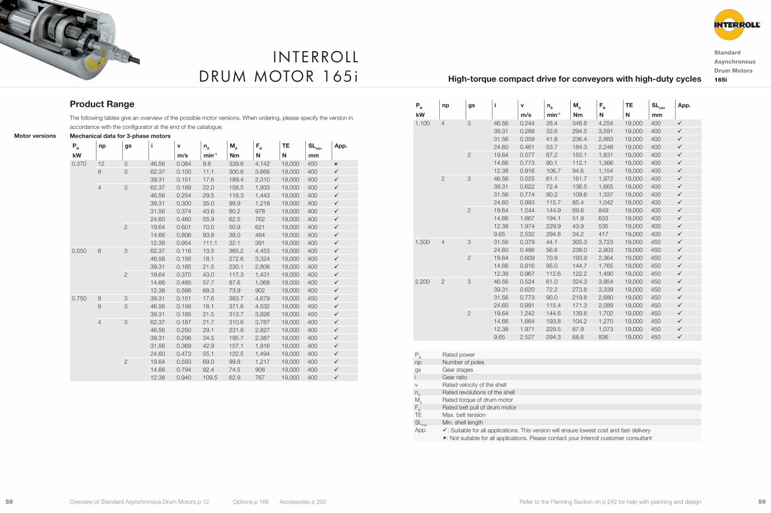
Interroll Drum motor 165i
Standard
Asynchronous
Drum Motors
165iHigh-torque compact drive for conveyors with high-duty cycles
Overview of Standard Asynchronous Drum Motors p 12 Options p 166 Accessories p 200
5958 Refer to the Planning Section on p 242 for help with planning and design
PN np gs i v nA MA FN TE SLmin App.
kW m/s min-1 Nm N N mm 1.100 4 3 46.56 0.244 28.4 348.8 4,254 19,000 400 9
39.31 0.288 33.6 294.5 3,591 19,000 400 931.56 0.359 41.8 236.4 2,883 19,000 400 924.60 0.461 53.7 184.3 2,248 19,000 400 9
2 19.64 0.577 67.2 150.1 1,831 19,000 400 914.66 0.773 90.1 112.1 1,366 19,000 400 912.38 0.916 106.7 94.6 1,154 19,000 400 9
2 3 46.56 0.525 61.1 161.7 1,972 19,000 400 939.31 0.622 72.4 136.5 1,665 19,000 400 931.56 0.774 90.2 109.6 1,337 19,000 400 924.60 0.993 115.7 85.4 1,042 19,000 400 9
2 19.64 1.244 144.9 69.6 849 19,000 400 914.66 1.667 194.1 51.9 633 19,000 400 912.38 1.974 229.9 43.9 535 19,000 400 99.65 2.532 294.8 34.2 417 19,000 400 9
1.500 4 3 31.56 0.379 44.1 305.3 3,723 19,000 450 924.60 0.486 56.6 238.0 2,903 19,000 450 9
2 19.64 0.609 70.9 193.9 2,364 19,000 450 914.66 0.816 95.0 144.7 1,765 19,000 450 912.38 0.967 112.6 122.2 1,490 19,000 450 9
2.200 2 3 46.56 0.524 61.0 324.3 3,954 19,000 450 939.31 0.620 72.2 273.8 3,339 19,000 450 931.56 0.773 90.0 219.8 2,680 19,000 450 924.60 0.991 115.4 171.3 2,089 19,000 450 9
2 19.64 1.242 144.6 139.6 1,702 19,000 450 914.66 1.664 193.8 104.2 1,270 19,000 450 912.38 1.971 229.5 87.9 1,073 19,000 450 99.65 2.527 294.3 68.6 836 19,000 450 9
PN Rated powernp Number of polesgs Gear stagesi Gear ratiov Rated velocity of the shellnA Rated revolutions of the shellMA Rated torque of drum motorFN Rated belt pull of drum motorTE Max. belt tensionSLmin Min. shell lengthApp. 9: Suitable for all applications. This version will ensure lowest cost and fast delivery
û: Not suitable for all applications. Please contact your Interroll customer consultant
Product RangeThe following tables give an overview of the possible motor versions. When ordering, please specify the version in
accordance with the configurator at the end of the catalogue.
Mechanical data for 3-phase motors
PN np gs i v nA MA FN TE SLmin App.
kW m/s min-1 Nm N N mm 0.370 12 3 46.56 0.084 9.8 339.6 4,142 19,000 450 û
8 3 62.37 0.100 11.1 300.6 3,666 19,000 400 939.31 0.151 17.6 189.4 2,310 19,000 400 9
4 3 62.37 0.189 22.0 158.5 1,933 19,000 400 946.56 0.254 29.5 118.3 1,443 19,000 400 939.31 0.300 35.0 99.9 1,218 19,000 400 931.56 0.374 43.6 80.2 978 19,000 400 924.60 0.480 55.9 62.5 762 19,000 400 9
2 19.64 0.601 70.0 50.9 621 19,000 400 914.66 0.806 93.8 38.0 464 19,000 400 912.38 0.954 111.1 32.1 391 19,000 400 9
0.550 6 3 62.37 0.116 13.5 365.2 4,453 19,000 400 946.56 0.156 18.1 272.6 3,324 19,000 400 939.31 0.185 21.5 230.1 2,806 19,000 400 9
2 19.64 0.370 43.0 117.3 1,431 19,000 400 914.66 0.495 57.7 87.6 1,068 19,000 400 912.38 0.586 68.3 73.9 902 19,000 400 9
0.750 8 3 39.31 0.151 17.6 383.7 4,679 19,000 450 96 3 46.56 0.156 18.1 371.6 4,532 19,000 450 9
39.31 0.185 21.5 313.7 3,826 19,000 450 94 3 62.37 0.187 21.7 310.6 3,787 19,000 400 9
46.56 0.250 29.1 231.8 2,827 19,000 400 939.31 0.296 34.5 195.7 2,387 19,000 400 931.56 0.369 42.9 157.1 1,916 19,000 400 924.60 0.473 55.1 122.5 1,494 19,000 400 9
2 19.64 0.593 69.0 99.8 1,217 19,000 400 914.66 0.794 92.4 74.5 908 19,000 400 912.38 0.940 109.5 62.9 767 19,000 400 9
Motor versions
Interroll Drum motor 165i
Standard
Asynchronous
Drum Motors
165iHigh-torque compact drive for conveyors with high-duty cycles
Overview of Standard Asynchronous Drum Motors p 12 Options p 166 Accessories p 200
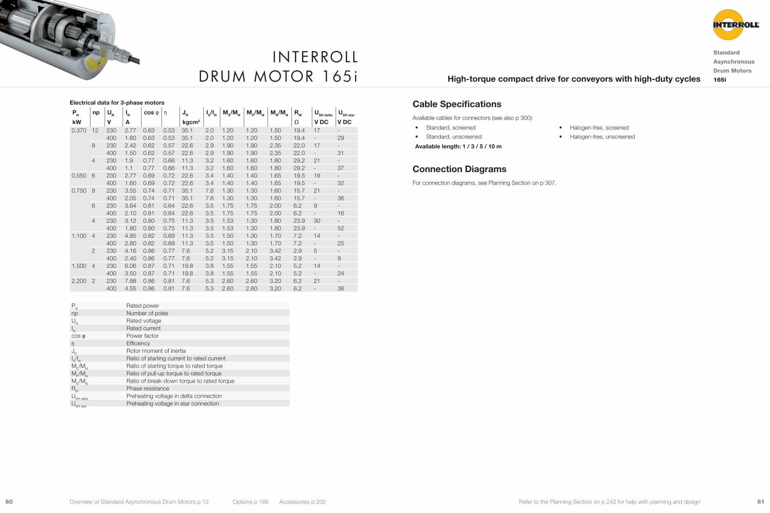
6160 Refer to the Planning Section on p 242 for help with planning and design
Cable SpecificationsAvailable cables for connectors (see also p 300):
• Standard, screened
• Standard, unscreened
• Halogen-free, screened
• Halogen-free, unscreened
Available length: 1 / 3 / 5 / 10 m
Connection DiagramsFor connection diagrams, see Planning Section on p 307.
Electrical data for 3-phase motors
PN np UN IN cos φ η JR IS/IN MS/MN MP/MN MB/MN RM USH delta USH star
kW V A kgcm2 Ω V DC V DC0.370 12 230 2.77 0.63 0.53 35.1 2.0 1.20 1.20 1.50 19.4 17 -
400 1.60 0.63 0.53 35.1 2.0 1.20 1.20 1.50 19.4 - 298 230 2.42 0.62 0.57 22.6 2.9 1.90 1.90 2.35 22.0 17 -
400 1.50 0.62 0.57 22.6 2.9 1.90 1.90 2.35 22.0 - 314 230 1.9 0.77 0.66 11.3 3.2 1.60 1.60 1.80 29.2 21 -
400 1.1 0.77 0.66 11.3 3.2 1.60 1.60 1.80 29.2 - 370.550 6 230 2.77 0.69 0.72 22.6 3.4 1.40 1.40 1.65 19.5 19 -
400 1.60 0.69 0.72 22.6 3.4 1.40 1.40 1.65 19.5 - 320.750 8 230 3.55 0.74 0.71 35.1 7.6 1.30 1.30 1.60 15.7 21 -
400 2.05 0.74 0.71 35.1 7.6 1.30 1.30 1.60 15.7 - 366 230 3.64 0.81 0.64 22.6 3.5 1.75 1.75 2.00 6.2 9 -
400 2.10 0.81 0.64 22.6 3.5 1.75 1.75 2.00 6.2 - 164 230 3.12 0.80 0.75 11.3 3.5 1.53 1.30 1.80 23.9 30 -
400 1.80 0.80 0.75 11.3 3.5 1.53 1.30 1.80 23.9 - 521.100 4 230 4.85 0.82 0.69 11.3 3.5 1.50 1.30 1.70 7.2 14 -
400 2.80 0.82 0.69 11.3 3.5 1.50 1.30 1.70 7.2 - 252 230 4.16 0.86 0.77 7.6 5.2 3.15 2.10 3.42 2.9 5 -
400 2.40 0.86 0.77 7.6 5.2 3.15 2.10 3.42 2.9 - 91.500 4 230 6.06 0.87 0.71 19.8 3.8 1.55 1.55 2.10 5.2 14 -
400 3.50 0.87 0.71 19.8 3.8 1.55 1.55 2.10 5.2 - 242.200 2 230 7.88 0.86 0.81 7.6 5.3 2.60 2.60 3.20 6.2 21 -
400 4.55 0.86 0.81 7.6 5.3 2.60 2.60 3.20 6.2 - 36
PN Rated powernp Number of polesUN Rated voltageIN Rated currentcos φ Power factorη EfficiencyJR Rotor moment of inertiaIS/IN Ratio of starting current to rated currentMS/MN Ratio of starting torque to rated torqueMP/MN Ratio of pull-up torque to rated torqueMB/MN Ratio of break-down torque to rated torqueRM Phase resistanceUSH delta Preheating voltage in delta connectionUSH star Preheating voltage in star connection
Interroll Drum motor 165i
Standard
Asynchronous
Drum Motors
165iHigh-torque compact drive for conveyors with high-duty cycles
Overview of Standard Asynchronous Drum Motors p 12 Options p 166 Accessories p 200

6362 Refer to the Planning Section on p 242 for help with planning and design
Dimensions
ØB
ØA
Ø13
0
FW = SL + 17
EL = SL + 4045 45
40
30
2020
1.51.5
SL
AGL = SL + 130
1/3 1/3 1/3
Fig.: Drum motor with straight connector
Type Ø Amm
Ø Bmm
165i crowned shell 164.0 162.0165i cylindrical shell 162.0 162.0165i cylindrical shell + key 162.0 162.0
20
22
21 20
24
22
Fig.: Straight connector, brass/nickel Fig.: Straight connector, stainless steel
Standard
dimensions
Connector
dimensions
Interroll Drum motor 165i
Standard
Asynchronous
Drum Motors
165iHigh-torque compact drive for conveyors with high-duty cycles
Overview of Standard Asynchronous Drum Motors p 12 Options p 166 Accessories p 200
1.5
20
22
20 20
Fig.: Straight cable outlet, PU shaft plug Fig.: Straight connector, standard / straight EMC
cable connector, brass
23
20 21
17.5
24
Ø30
Fig.: Straight connector / Feedback device,
brass/nickel
Fig.: Elbow connector, stainless steel
17.5
24
Ø30
22 32
10
20 20
Fig.: Elbow connector / Feedback device,
stainless steel
Fig.: Elbow connector, technopolymer
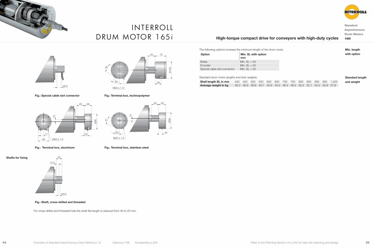
6564 Refer to the Planning Section on p 242 for help with planning and design
20
26.5
50
30° 39
7243
Ø10
5
M20 x 1.5
Fig.: Special cable slot connector Fig.: Terminal box, technopolymer
65
17 22
46
Ø95
14
M20 x 1.5
4347
20° 25
4343
Ø99
14
M20 x 1.5
Fig.: Terminal box, aluminium Fig.: Terminal box, stainless steel
M10
12.5
25
Fig.: Shaft, cross-drilled and threaded
For cross-drilled and threaded hole the shaft flat length is reduced from 45 to 25 mm.
Shafts for fixing
The following options increase the minimum length of the drum motor.
Option Min. SL with option mm
Brake Min. SL + 50Encoder Min. SL + 50Special cable slot connector Min. SL + 50
Standard drum motor lengths and their weights:
Shell length SL in mm 400 450 500 550 600 650 700 750 800 850 900 950 1,000Average weight in kg 35.0 36.9 38.8 40.7 42.6 44.5 46.4 48.3 50.2 52.1 54.0 55.9 57.8
Min. length
with option
Standard length
and weight
Interroll Drum motor 165i
Standard
Asynchronous
Drum Motors
165iHigh-torque compact drive for conveyors with high-duty cycles
Overview of Standard Asynchronous Drum Motors p 12 Options p 166 Accessories p 200

6766 Refer to the Planning Section on p 242 for help with planning and design
Material VersionsYou can choose the following versions of drum body components and electrical connection. The versions depend
on the material of the components.
Component Version Material
Aluminium Mild steel
Stainless steel
Brass / Nickel
Techno-polymer
Shell Crowned 9 9Cylindrical 9 9Special crowns and grooves 9 9
End housing Standard 9 9With V-grooves 9With O-grooves 9With chain sprockets 9 9
Shaft Standard 9 9Cross-drilled thread, M10 9 9
External seal Galvanised labyrinth 9Labyrinth 9Labyrinth with FPM 9
Electrical connector
Straight connector (for cables see p 300) 9 9 9Elbow connector (for cables see p 300) 9 9Terminal box 9 9 9
Please contact your Interroll customer consultant for further versions.
Options• Lagging for friction drive belts, see p 168
• Lagging for plastic modular belts, see p 174
• Lagging for positive drive solid homogeneous
belts, see p 178
• Backstops, see p 188
• Balancing, see p 189
• Electromagnetic brakes, see p 190
• Rectifiers, see p 194
• Encoders, see p 196
• Food-grade oil (EU, FDA), see p 302
• Low temperature oil, see p 302
• cULus safety certifications, see p 301
• Non-horizontal mounting (more than ± 5°), see p 280
• 2-speed motors, see p 294
Note: Combination of encoder and electromagnetic brake is not possible.
Accessories• Mounting brackets, see p 204
• Idler pulleys, see p 218 to p 230
• Conveyor rollers, see p 232
• IFI - IP55 Frequency Inverter, see p 238
Product DescriptionThis drum motor is typically used for heavy-duty handling applications.
9 Conveyors with high-duty cycles
9 Belts with side walls or cross cleats
9 Logistics applications
9 Airport and postal conveyors
9 Warehouse loading conveyors
9 Telescopic conveyors
9 Agricultural plants
9 Food processing
9 Dry, wet and wash-down applications
9 Salt-water-resistant aluminium bearing housings
9 3-phase AC induction motor
9 Dual voltage
9 Integral motor protection
9 Steel-hardened helical spur gear
9 Low noise
9 Maintenance-free
9 Lifetime lubricated
9 Reversible
9 Reinforced shaft for SL above 1,000 mm
Note: For applications with positive drive belts please use a frequency converter or cool-running drum motor.
Technical DataElectrical data
Motor type Asynchronous squirrel cage motor, IEC 34 (VDE 0530)Insulation class of motor windings Class F, IEC 34 (VDE 0530)Voltage 230/400 V ±5 % (IEC 34/38)
Special voltage on requestFrequency 50/60 HzInternal shaft sealing system Double-lipped, FPM or NBRProtection rate IP66Thermal protection (see p 302) Bi-metal switchOperation mode (see p 279) S1Ambient temperature, 3-phase motor (see p 263) +5 to +40 °C
General technical data Max. shell length SL 1,600 mm
All data and values in this catalogue refer to 50 Hz operation.
Order InformationPlease refer to the order information at the end of the catalogue.
Applications
Characteristics
Interroll Drum motor 216i
Standard
Asynchronous
Drum Motors
216iStrong powerful drive for conveyors with high-duty cycles
Overview of Standard Asynchronous Drum Motors p 12 Options p 166 Accessories p 200
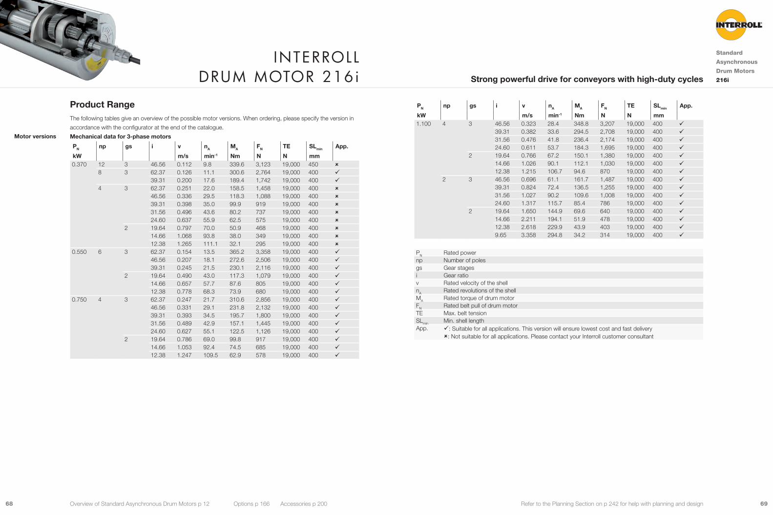
6968 Refer to the Planning Section on p 242 for help with planning and design
PN np gs i v nA MA FN TE SLmin App.
kW m/s min-1 Nm N N mm 1.100 4 3 46.56 0.323 28.4 348.8 3,207 19,000 400 9
39.31 0.382 33.6 294.5 2,708 19,000 400 931.56 0.476 41.8 236.4 2,174 19,000 400 924.60 0.611 53.7 184.3 1,695 19,000 400 9
2 19.64 0.766 67.2 150.1 1,380 19,000 400 914.66 1.026 90.1 112.1 1,030 19,000 400 912.38 1.215 106.7 94.6 870 19,000 400 9
2 3 46.56 0.696 61.1 161.7 1,487 19,000 400 939.31 0.824 72.4 136.5 1,255 19,000 400 931.56 1.027 90.2 109.6 1,008 19,000 400 924.60 1.317 115.7 85.4 786 19,000 400 9
2 19.64 1.650 144.9 69.6 640 19,000 400 914.66 2.211 194.1 51.9 478 19,000 400 912.38 2.618 229.9 43.9 403 19,000 400 99.65 3.358 294.8 34.2 314 19,000 400 9
PN Rated powernp Number of polesgs Gear stagesi Gear ratiov Rated velocity of the shellnA Rated revolutions of the shellMA Rated torque of drum motorFN Rated belt pull of drum motorTE Max. belt tensionSLmin Min. shell lengthApp. 9: Suitable for all applications. This version will ensure lowest cost and fast delivery
û: Not suitable for all applications. Please contact your Interroll customer consultant
Product RangeThe following tables give an overview of the possible motor versions. When ordering, please specify the version in
accordance with the configurator at the end of the catalogue.
Mechanical data for 3-phase motors
PN np gs i v nA MA FN TE SLmin App.
kW m/s min-1 Nm N N mm 0.370 12 3 46.56 0.112 9.8 339.6 3,123 19,000 450 û
8 3 62.37 0.126 11.1 300.6 2,764 19,000 400 939.31 0.200 17.6 189.4 1,742 19,000 400 9
4 3 62.37 0.251 22.0 158.5 1,458 19,000 400 û46.56 0.336 29.5 118.3 1,088 19,000 400 û39.31 0.398 35.0 99.9 919 19,000 400 û31.56 0.496 43.6 80.2 737 19,000 400 û24.60 0.637 55.9 62.5 575 19,000 400 û
2 19.64 0.797 70.0 50.9 468 19,000 400 û14.66 1.068 93.8 38.0 349 19,000 400 û12.38 1.265 111.1 32.1 295 19,000 400 û
0.550 6 3 62.37 0.154 13.5 365.2 3,358 19,000 400 946.56 0.207 18.1 272.6 2,506 19,000 400 939.31 0.245 21.5 230.1 2,116 19,000 400 9
2 19.64 0.490 43.0 117.3 1,079 19,000 400 914.66 0.657 57.7 87.6 805 19,000 400 912.38 0.778 68.3 73.9 680 19,000 400 9
0.750 4 3 62.37 0.247 21.7 310.6 2,856 19,000 400 946.56 0.331 29.1 231.8 2,132 19,000 400 939.31 0.393 34.5 195.7 1,800 19,000 400 931.56 0.489 42.9 157.1 1,445 19,000 400 924.60 0.627 55.1 122.5 1,126 19,000 400 9
2 19.64 0.786 69.0 99.8 917 19,000 400 914.66 1.053 92.4 74.5 685 19,000 400 912.38 1.247 109.5 62.9 578 19,000 400 9
Motor versions
Interroll Drum motor 216i
Standard
Asynchronous
Drum Motors
216iStrong powerful drive for conveyors with high-duty cycles
Overview of Standard Asynchronous Drum Motors p 12 Options p 166 Accessories p 200

7170 Refer to the Planning Section on p 242 for help with planning and design
Cable SpecificationsAvailable cables for connectors (see also p 300):
• Standard, screened
• Standard, unscreened
• Halogen-free, screened
• Halogen-free, unscreened
Available length: 1 / 3 / 5 / 10 m
Connection DiagramsFor connection diagrams, see Planning Section on p 307.
Electrical data for 3-phase motors
PN np UN IN cos φ η JR IS/IN MS/MN MP/MN MB/MN RM USH delta USH star
kW V A kgcm2 Ω V DC V DC0.370 12 230 2.77 0.63 0.53 35.1 2.0 1.20 1.20 1.50 19.4 17 -
400 1.60 0.63 0.53 35.1 2.0 1.20 1.20 1.50 19.4 - 298 230 2.42 0.62 0.57 22.6 2.9 1.90 1.90 2.35 22.0 17 -
400 1.50 0.62 0.57 22.6 2.9 1.90 1.90 2.35 22.0 - 314 230 1.9 0.77 0.66 11.3 3.2 1.60 1.60 1.80 29.2 21 -
400 1.1 0.77 0.66 11.3 3.2 1.60 1.60 1.80 29.2 - 370.550 6 230 2.77 0.69 0.72 22.6 3.4 1.40 1.40 1.65 19.5 19 -
400 1.60 0.69 0.72 22.6 3.4 1.40 1.40 1.65 19.5 - 320.750 4 230 3.12 0.80 0.75 11.3 3.5 1.53 1.30 1.80 23.9 30 -
400 1.80 0.80 0.75 11.3 3.5 1.53 1.30 1.80 23.9 - 521.100 4 230 4.85 0.82 0.69 11.3 3.5 1.50 1.30 1.70 7.2 14 -
400 2.80 0.82 0.69 11.3 3.5 1.50 1.30 1.70 7.2 - 252 230 4.16 0.86 0.77 7.6 5.2 3.15 2.10 3.42 2.9 5 -
400 2.40 0.86 0.77 7.6 5.2 3.15 2.10 3.42 2.9 - 9
PN Rated powernp Number of polesUN Rated voltageIN Rated currentcos φ Power factorη EfficiencyJR Rotor moment of inertiaIS/IN Ratio of starting current to rated currentMS/MN Ratio of starting torque to rated torqueMP/MN Ratio of pull-up torque to rated torqueMB/MN Ratio of break-down torque to rated torqueRM Phase resistanceUSH delta Preheating voltage in delta connectionUSH star Preheating voltage in star connection
Interroll Drum motor 216i
Standard
Asynchronous
Drum Motors
216iStrong powerful drive for conveyors with high-duty cycles
Overview of Standard Asynchronous Drum Motors p 12 Options p 166 Accessories p 200

7372 Refer to the Planning Section on p 242 for help with planning and design
Dimensions
20 SL
1/31/31/3
Ø13
0
20
EL = SL + 4045 45
30
40ØB
ØA
1.5 1.5
FW = SL + 17
AGL = SL + 130
Fig.: Drum motor with straight connector
Type Ø Amm
Ø Bmm
216i crowned shell 217.5 215.5216i cylindrical shell 215.5 215.5
20
22
21 20
24
22
Fig.: Straight connector, brass/nickel Fig.: Straight connector, stainless steel
Standard
dimensions
Connector
dimensions
1.5
20
22
20 20
Fig.: Straight cable outlet, PU shaft plug Fig.: Straight connector, standard / straight EMC
cable connector, brass
23
20 21
17.5
24
Ø30
Fig.: Straight connector / Feedback device,
brass/nickel
Fig.: Elbow connector, stainless steel
17.5
24
Ø30
22 32
10
20 20
Fig.: Elbow connector / Feedback device,
stainless steel
Fig.: Elbow connector, technopolymer
Interroll Drum motor 216i
Standard
Asynchronous
Drum Motors
216iStrong powerful drive for conveyors with high-duty cycles
Overview of Standard Asynchronous Drum Motors p 12 Options p 166 Accessories p 200
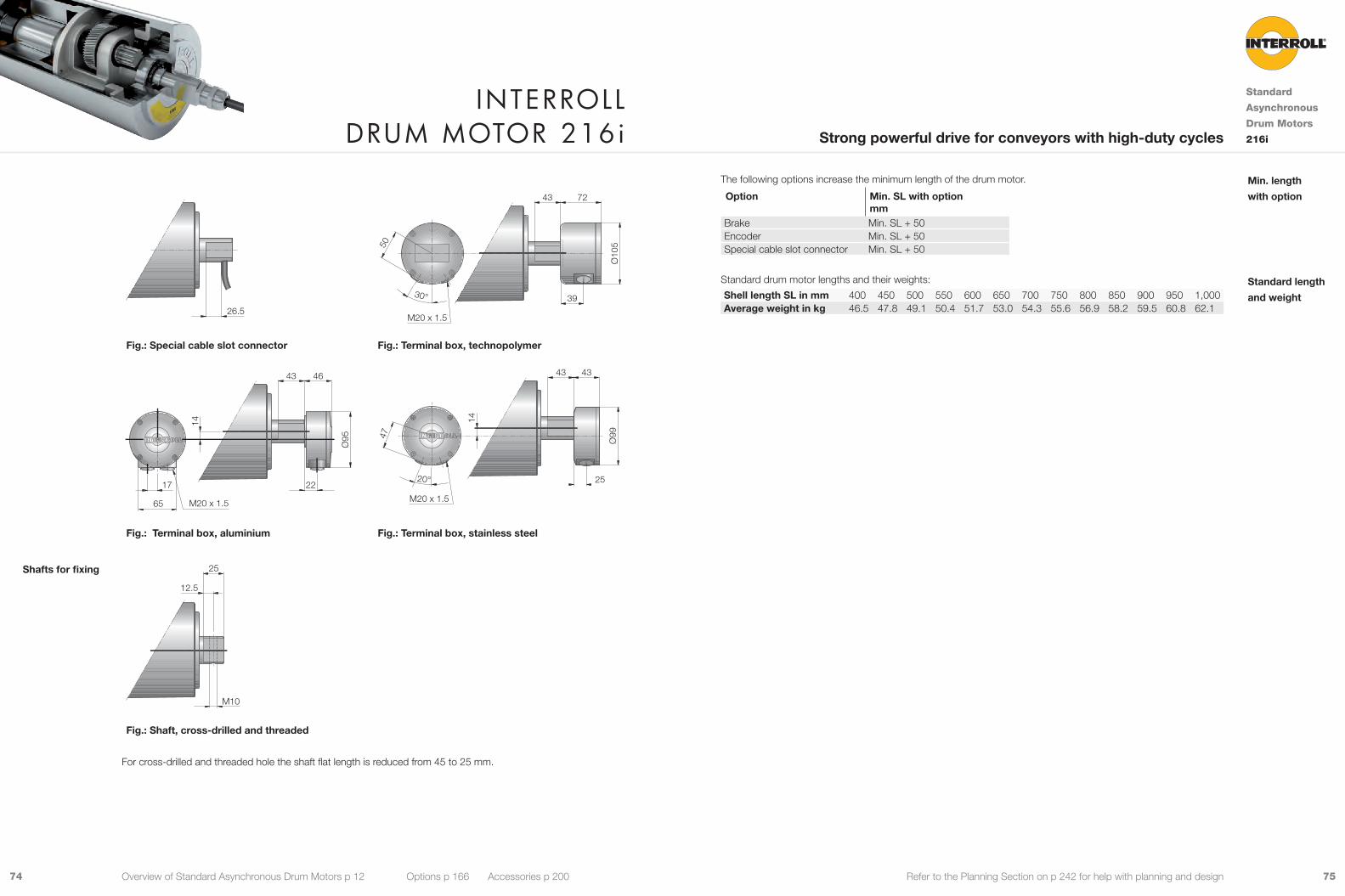
7574 Refer to the Planning Section on p 242 for help with planning and design
20
26.5
50
30° 39
7243
Ø10
5
M20 x 1.5
Fig.: Special cable slot connector Fig.: Terminal box, technopolymer
65
17 22
46
Ø95
14
M20 x 1.5
4347
20° 25
4343
Ø99
14
M20 x 1.5
Fig.: Terminal box, aluminium Fig.: Terminal box, stainless steel
M10
12.5
25
Fig.: Shaft, cross-drilled and threaded
For cross-drilled and threaded hole the shaft flat length is reduced from 45 to 25 mm.
Shafts for fixing
Interroll Drum motor 216i
Standard
Asynchronous
Drum Motors
216iStrong powerful drive for conveyors with high-duty cycles
Overview of Standard Asynchronous Drum Motors p 12 Options p 166 Accessories p 200
The following options increase the minimum length of the drum motor.
Option Min. SL with option mm
Brake Min. SL + 50Encoder Min. SL + 50Special cable slot connector Min. SL + 50
Standard drum motor lengths and their weights:
Shell length SL in mm 400 450 500 550 600 650 700 750 800 850 900 950 1,000Average weight in kg 46.5 47.8 49.1 50.4 51.7 53.0 54.3 55.6 56.9 58.2 59.5 60.8 62.1
Min. length
with option
Standard length
and weight
7776 Refer to the Planning Section on p 242 for help with planning and design
Material VersionsYou can choose the following versions of drum body components and electrical connection. The versions depend
on the material of the components.
Component Version Material
Aluminium Mild steel
Stainless steel
Brass / Nickel
Techno-polymer
Shell Crowned 9 9Cylindrical 9 9Special crowns and grooves 9 9
End housing Standard 9 9With V-grooves 9With O-grooves 9With chain sprockets 9
Shaft Standard 9 9Cross-drilled thread. M10 9 9
External seal Galvanised labyrinth 9Labyrinth 9Labyrinth with FPM 9
Electrical connector
Straight connector (for cables see p 300) 9 9 9Elbow connector (for cables see p 300) 9 9Terminal box 9 9 9
Please contact your Interroll customer consultant for further versions.
Options• Lagging for friction drive belts, see p 168
• Lagging for plastic modular belts, see p 174
• Lagging for positive drive solid homogeneous
belts, see p 178
• Backstops, see p 188
• Balancing, see p 189
• Electromagnetic brakes, see p 190
• Rectifiers, see p 194
• Encoders, see p 196
• Food-grade oil (EU, FDA), see p 302
• Low temperature oil, see p 302
• cULus safety certifications, see p 301
• Non-horizontal mounting (more than ± 5°),
see p 280
• 2-speed motors, see p 294
Note: Combination of encoder and electromagnetic brake is not possible.
Accessories• Mounting brackets, see p 204
• Idler pulleys, see p 218 to p 230
• Conveyor rollers, see p 232
• IFI - IP55 Frequency Inverter, see p 238
Product DescriptionThis drum motor is typically used for heavy-duty handling applications.
9 Conveyors with heavy loads
9 Belts with side walls or cross cleats
9 Logistics applications
9 Airport and postal conveyors
9 Warehouse loading conveyors
9 Telescopic conveyors
9 Agricultural plants
9 Food processing
9 Dry, wet and wash-down applications
9 Salt-water-resistant aluminium bearing housings
9 3-phase AC induction motor
9 Dual voltage
9 Integral motor protection
9 Steel-hardened helical spur gear
9 Low noise
9 Maintenance-free
9 Lifetime lubricated
9 Reversible
9 Reinforced shaft for SL above 1,200 mm
Note: For applications with positive drive belts please use a frequency converter.
Technical DataElectrical data
Motor type Asynchronous squirrel cage motor, IEC 34 (VDE 0530)Insulation class of motor windings Class F, IEC 34 (VDE 0530)Voltage 230/400 V ±5 % (IEC 34/38)
Special voltage on requestFrequency 50/60 HzInternal shaft sealing system Double-lipped, FPM or NBRProtection rate IP66Thermal protection (see p 302) Bi-metal switchOperation mode (see p 279) S1Ambient temperature. 3-phase motor (see p 263) +5 to +40 °C
General technical data Max. shell length SL 1,600 mm
All data and values in this catalogue refer to 50 Hz operation.
Order InformationPlease refer to the order information at the end of the catalogue.
Applications
Characteristics
Interroll Drum motor 217i
Standard
Asynchronous
Drum Motors
217iHigh torque compact drive for heavy-duty conveyors
Overview of Standard Asynchronous Drum Motors p 12 Options p 166 Accessories p 200

7978 Refer to the Planning Section on p 242 for help with planning and design
Electrical data for 3-phase motors
PN np UN IN cos φ η JR IS/IN MS/MN MP/MN MB/MN RM USH delta USH star
kW V A kgcm2 Ω V DC V DC1.100 8 230 5.54 0.81 0.61 86.0 4.5 1.80 1.70 2.20 6.3 14 -
400 3.20 0.81 0.61 86.0 4.5 1.80 1.70 2.20 6.3 - 241.500 6 230 6.93 0.82 0.66 86.0 4.8 2.10 1.90 2.50 4.3 12 -
400 4.00 0.82 0.66 86.0 4.8 2.10 1.90 2.50 4.3 - 214 230 6.41 0.87 0.67 49.6 5.5 2.20 1.80 2.50 3.6 10 -
400 3.70 0.87 0.67 49.6 5.5 2.20 1.80 2.50 3.6 - 172.200 6 230 9.87 0.80 0.70 86.0 5.0 2.10 1.90 2.50 3.6 14 -
400 5.70 0.80 0.70 86.0 5.0 2.10 1.90 2.50 3.6 - 254 230 9.01 0.87 0.70 60.0 5.9 2.40 2.30 2.90 3.5 14 -
400 5.20 0.87 0.70 60.0 5.9 2.40 2.30 2.90 3.5 - 242 230 8.83 0.88 0.71 26.0 6.4 2.60 2.30 3.02 3.0 11 -
400 5.10 0.88 0.71 26.0 6.4 2.60 2.30 3.02 3.0 - 203.000 4 230 12.12 0.82 0.76 46.9 5.0 2.40 2.30 2.90 1.9 9 -
400 7.00 0.82 0.76 46.9 5.0 2.40 2.30 2.90 1.9 - 162 230 11.52 0.82 0.80 38.1 6.5 2.60 2.40 3.40 1.6 7 -
400 6.65 0.82 0.80 38.1 6.5 2.60 2.40 3.40 1.6 - 13
PN Rated powernp Number of polesUN Rated voltageIN Rated currentcos φ Power factorη EfficiencyJR Rotor moment of inertiaIS/IN Ratio of starting current to rated currentMS/MN Ratio of starting torque to rated torqueMP/MN Ratio of pull-up torque to rated torqueMB/MN Ratio of break-down torque to rated torqueRM Phase resistanceUSH delta Preheating voltage in delta connectionUSH star Preheating voltage in star connection
Cable Specifications
Available cables for connectors (see also p 300):
• Standard, screened
• Standard. unscreened
• Halogen-free, screened
• Halogen-free, unscreened
Available length: 1 / 3 / 5 / 10 m
Connection DiagramsFor connection diagrams, see Planning Section on p 307.
Product RangeThe following tables give an overview of the possible motor versions. When ordering, please specify the version in
accordance with the configurator at the end of the catalogue.
Mechanical data for 3-phase motors
PN np gs i v nA MA FN TE SLmin App.kW m/s min-1 Nm N N mm 1.100 8 2 31.11 0.254 22.3 451.8 4,154 19,000 500 9
27.53 0.288 25.2 399.8 3,676 19,000 500 920.10 0.394 34.6 291.9 2,684 19,000 500 916.80 0.471 41.4 244.0 2,243 19,000 500 9
1.500 6 2 27.53 0.397 34.9 394.5 3,628 19,000 500 920.10 0.544 47.8 288.1 2,649 19,000 500 916.80 0.651 57.1 240.7 2,214 19,000 500 9
4 2 31.11 0.516 45.3 303.6 2,791 19,000 550 927.53 0.583 51.2 268.7 2,470 19,000 500 920.10 0.799 70.1 196.2 1,804 19,000 500 916.80 0.956 83.9 163.9 1,507 19,000 500 912.53 1.281 112.5 122.3 1,124 19,000 500 9
2.200 6 2 20.10 0.529 46.5 434.2 3,993 19,000 500 916.80 0.633 55.6 362.9 3,337 19,000 500 9
4 2 31.11 0.520 45.6 442.2 4,066 19,000 500 927.53 0.587 51.6 391.4 3,599 19,000 500 920.10 0.804 70.6 285.7 2,627 19,000 500 916.80 0.963 84.5 238.8 2,196 19,000 500 912.53 1.291 113.3 178.1 1,638 19,000 500 9
2 2 27.53 1.156 101.5 198.9 1,829 19,000 500 920.10 1.583 139.0 145.2 1,335 19,000 500 916.80 1.894 166.3 121.3 1,116 19,000 500 912.53 2.539 223.0 90.5 832 19,000 500 9
3.000 4 2 27.53 0.587 51.6 533.6 4,907 19,000 500 920.10 0.804 70.6 389.6 3,583 19,000 500 916.80 0.963 84.5 325.6 2,994 19,000 500 912.53 1.291 113.3 242.9 2,233 19,000 500 9
2 2 27.53 1.163 102.1 269.5 2,478 19,000 500 920.10 1.593 139.9 196.7 1,809 19,000 500 916.80 1.906 167.4 164.4 1,512 19,000 500 912.53 2.556 224.4 122.6 1.128 19.000 500 9
PN Rated powernp Number of polesgs Gear stagesi Gear ratiov Rated velocity of the shellnA Rated revolutions of the shellMA Rated torque of drum motorFN Rated belt pull of drum motorTE Max. belt tensionSLmin Min. shell lengthApp. 9: Suitable for all applications. This version will ensure lowest cost and fast delivery
û: Not suitable for all applications. Please contact your Interroll customer consultant
Motor versions
Interroll Drum motor 217i
Standard
Asynchronous
Drum Motors
217iHigh torque compact drive for heavy-duty conveyors
Overview of Standard Asynchronous Drum Motors p 12 Options p 166 Accessories p 200

8180 Refer to the Planning Section on p 242 for help with planning and design
1.5
20
22
20 20
Fig.: Straight cable outlet, PU shaft plug Fig.: Straight connector, standard / straight EMC
cable connector, brass
23
20 21
17.5
24
Ø30
Fig.: Straight connector / Feedback device,
brass/nickel
Fig.: Elbow connector, stainless steel
17.5
24
Ø30
22 32
10
20 20
Fig.: Elbow connector / Feedback device,
stainless steel
Fig.: Elbow connector, technopolymer
Dimensions
20 SL
1/31/31/3
Ø13
0
20
EL = SL + 4045 45
30
40ØB
ØA
1.5 1.5
FW = SL + 17
AGL = SL + 130
Fig.: Drum motor with straight connector
Type Ø Amm
Ø Bmm
217i crowned shell 217.5 215.5217i cylindrical shell 215.5 215.5
20
22
21 20
24
22
Fig.: Straight connector, brass/nickel Fig.: Straight connector, stainless steel
Standard
dimensions
Connector
dimensions
Interroll Drum motor 217i
Standard
Asynchronous
Drum Motors
217iHigh torque compact drive for heavy-duty conveyors
Overview of Standard Asynchronous Drum Motors p 12 Options p 166 Accessories p 200

8382 Refer to the Planning Section on p 242 for help with planning and design
20
26.5
50
30° 39
7243
Ø10
5
M20 x 1.5
Fig.: Special cable slot connector Fig.: Terminal box, technopolymer
65
17 22
46
Ø95
14
M20 x 1.5
4347
20° 25
4343
Ø99
14
M20 x 1.5
Fig.: Terminal box, aluminium Fig.: Terminal box, stainless steel
M10
12.5
25
Fig.: Shaft, cross-drilled and threaded
For cross-drilled and threaded hole the shaft flat length is reduced from 45 to 25 mm.
Shafts for fixing
The following options increase the minimum length of the drum motor.
Option Min. SL with option mm
Brake Min. SL + 50Encoder Min. SL + 50Special cable slot connector Min. SL + 50
Standard drum motor lengths and their weights:
Shell length SL in mm 500 550 600 650 700 750 800 850 900 950 1.000Average weight in kg 65 70 72 74 76 78 80 82 84 86 88
Min. length
with option
Standard length
and weight
Interroll Drum motor 217i
Standard
Asynchronous
Drum Motors
217iHigh torque compact drive for heavy-duty conveyors
Overview of Standard Asynchronous Drum Motors p 12 Options p 166 Accessories p 200

8584 Refer to the Planning Section on p 242 for help with planning and design
Material VersionsYou can choose the following versions of drum body components and electrical connection. The versions depend
on the material of the components.
Component Version Material
Mild steel Stainless steel
Brass / Nickel
Techno-polymer
Shell Crowned 9Cylindrical 9Special crowns and grooves 9
End housing Standard, painted 9 9Shaft Standard 9 9External seal Cover IP65 9
Labyrinth IP66 9Electrical connector
Straight connector (for cables see p 300) 9 9Terminal box 9
Please contact your Interroll customer consultant for further versions.
Options• Lagging for friction drive belts, see p 168
• Backstops, see p 188
• Electromagnetic brakes, see p 190
• Rectifiers, see p 194
• Food-grade oil (EU, FDA), see p 302
• Low temperature oil, see p 302
• UL/cUL safety certifications, see
Note: For wet or food applications, the shell must be protected with hot vulcanised NBR lagging or other rust-free
coating, see p 168.
Accessories• Mounting brackets, see p 204
• Idler pulleys, see p 218 to p 230
• Conveyor rollers, see p 232
• IFI - IP55 Frequency Inverter, see p 238
Product DescriptionThis drum motor is typically used for heavy-duty handling applications.
9 Belts with side walls or cross cleats
9 Logistics applications
9 Airport and postal conveyors
9 Warehouse loading conveyors
9 Telescopic conveyors
9 Agricultural plants
9 Food processing
9 Dry, wet and wash-down applications
9 Mild steel, painted bearing housings
9 3-phase AC induction motor
9 Dual voltage (with terminal box)
9 Integral motor protection
9 Steel-hardened helical spur gear
9 Low noise
9 Maintenance-free
9 Lifetime lubricated
9 Reversible
9 Reinforced shaft for SL above 1,400 mm
Note: For applications without belt please use a frequency converter.
Technical DataElectrical data
Motor type Asynchronous squirrel cage motor, IEC 34 (VDE 0530)Insulation class of motor windings Class F, IEC 34 (VDE 0530)Voltage 230/400 V ±5 % (IEC 34/38)
Special voltage on request400/690 V ±5 % (IEC 34/38)
Frequency 50/60 HzInternal shaft sealing system Double-lipped, NBRProtection rate IP65Thermal protection (see p 302) Bi-metal switchOperation mode (see p 279) S1Ambient temperature, 3-phase motor (see p 263) +5 to +40 °C
General technical data Max. shell length SL 1,750 mm
All data and values in this catalogue refer to 50 Hz operation.
Order InformationPlease refer to the order information at the end of the catalogue.
Applications
Characteristics
Interroll Drum motor 315i
Standard
Asynchronous
Drum Motors
315iPowerful high torque drive for heavy-duty conveyors
Overview of Standard Asynchronous Drum Motors p 12 Options p 166 Accessories p 200
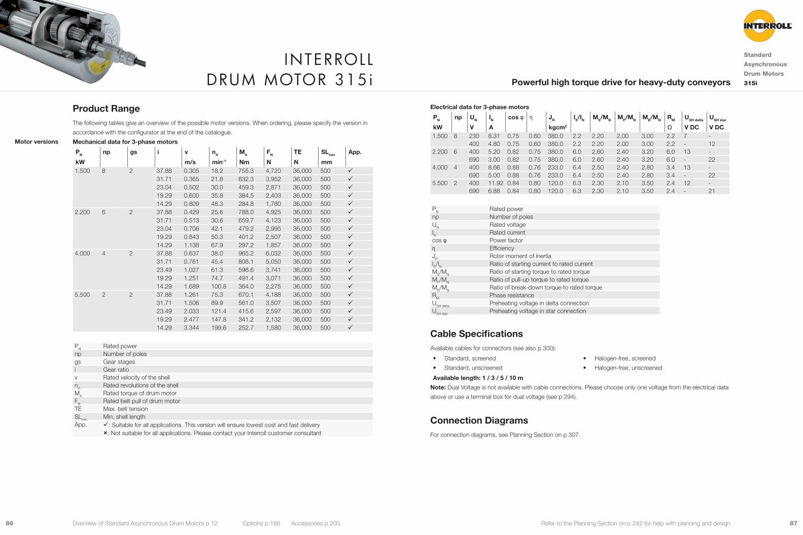
8786 Refer to the Planning Section on p 242 for help with planning and design
Electrical data for 3-phase motors
PN np UN IN cos φ η JR IS/IN MS/MN MP/MN MB/MN RM USH delta USH star
kW V A kgcm2 Ω V DC V DC1.500 8 230 8.31 0.75 0.60 380.0 2.2 2.20 2.00 3.00 2.2 7 -
400 4.80 0.75 0.60 380.0 2.2 2.20 2.00 3.00 2.2 - 122.200 6 400 5.20 0.82 0.75 380.0 6.0 2.60 2.40 3.20 6.0 13 -
690 3.00 0.82 0.75 380.0 6.0 2.60 2.40 3.20 6.0 - 224.000 4 400 8.66 0.88 0.76 233.0 6.4 2.50 2.40 2.80 3.4 13 -
690 5.00 0.88 0.76 233.0 6.4 2.50 2.40 2.80 3.4 - 225.500 2 400 11.92 0.84 0.80 120.0 6.3 2.30 2.10 3.50 2.4 12 -
690 6.88 0.84 0.80 120.0 6.3 2.30 2.10 3.50 2.4 - 21
PN Rated powernp Number of polesUN Rated voltageIN Rated currentcos φ Power factorη EfficiencyJR Rotor moment of inertiaIS/IN Ratio of starting current to rated currentMS/MN Ratio of starting torque to rated torqueMP/MN Ratio of pull-up torque to rated torqueMB/MN Ratio of break-down torque to rated torqueRM Phase resistanceUSH delta Preheating voltage in delta connectionUSH star Preheating voltage in star connection
Cable SpecificationsAvailable cables for connectors (see also p 300):
• Standard, screened
• Standard, unscreened
• Halogen-free, screened
• Halogen-free, unscreened
Available length: 1 / 3 / 5 / 10 m
Note: Dual Voltage is not available with cable connections. Please choose only one voltage from the electrical data
above or use a terminal box for dual voltage (see p 294).
Connection DiagramsFor connection diagrams, see Planning Section on p 307.
Product RangeThe following tables give an overview of the possible motor versions. When ordering, please specify the version in
accordance with the configurator at the end of the catalogue.
Mechanical data for 3-phase motors
PN np gs i v nA MA FN TE SLmin App.
kW m/s min-1 Nm N N mm 1.500 8 2 37.88 0.305 18.2 755.3 4,720 36,000 500 9
31.71 0.365 21.8 632.3 3,952 36,000 500 923.04 0.502 30.0 459.3 2,871 36,000 500 919.29 0.600 35.8 384.5 2,403 36,000 500 914.29 0.809 48.3 284.8 1,780 36,000 500 9
2.200 6 2 37.88 0.429 25.6 788.0 4,925 36,000 500 931.71 0.513 30.6 659.7 4,123 36,000 500 923.04 0.706 42.1 479.2 2,995 36,000 500 919.29 0.843 50.3 401.2 2,507 36,000 500 914.29 1.138 67.9 297.2 1,857 36,000 500 9
4.000 4 2 37.88 0.637 38.0 965.2 6,032 36,000 500 931.71 0.761 45.4 808.1 5,050 36,000 500 923.49 1.027 61.3 598.6 3,741 36,000 500 919.29 1.251 74.7 491.4 3,071 36,000 500 914.29 1.689 100.8 364.0 2,275 36,000 500 9
5.500 2 2 37.88 1.261 75.3 670.1 4,188 36,000 500 931.71 1.506 89.9 561.0 3,507 36,000 500 923.49 2.033 121.4 415.6 2,597 36,000 500 919.29 2.477 147.8 341.2 2,132 36,000 500 914.29 3.344 199.6 252.7 1,580 36,000 500 9
PN Rated powernp Number of polesgs Gear stagesi Gear ratiov Rated velocity of the shellnA Rated revolutions of the shellMA Rated torque of drum motorFN Rated belt pull of drum motorTE Max. belt tensionSLmin Min. shell lengthApp. 9: Suitable for all applications. This version will ensure lowest cost and fast delivery
û: Not suitable for all applications. Please contact your Interroll customer consultant
Motor versions
Interroll Drum motor 315i
Standard
Asynchronous
Drum Motors
315iPowerful high torque drive for heavy-duty conveyors
Overview of Standard Asynchronous Drum Motors p 12 Options p 166 Accessories p 200
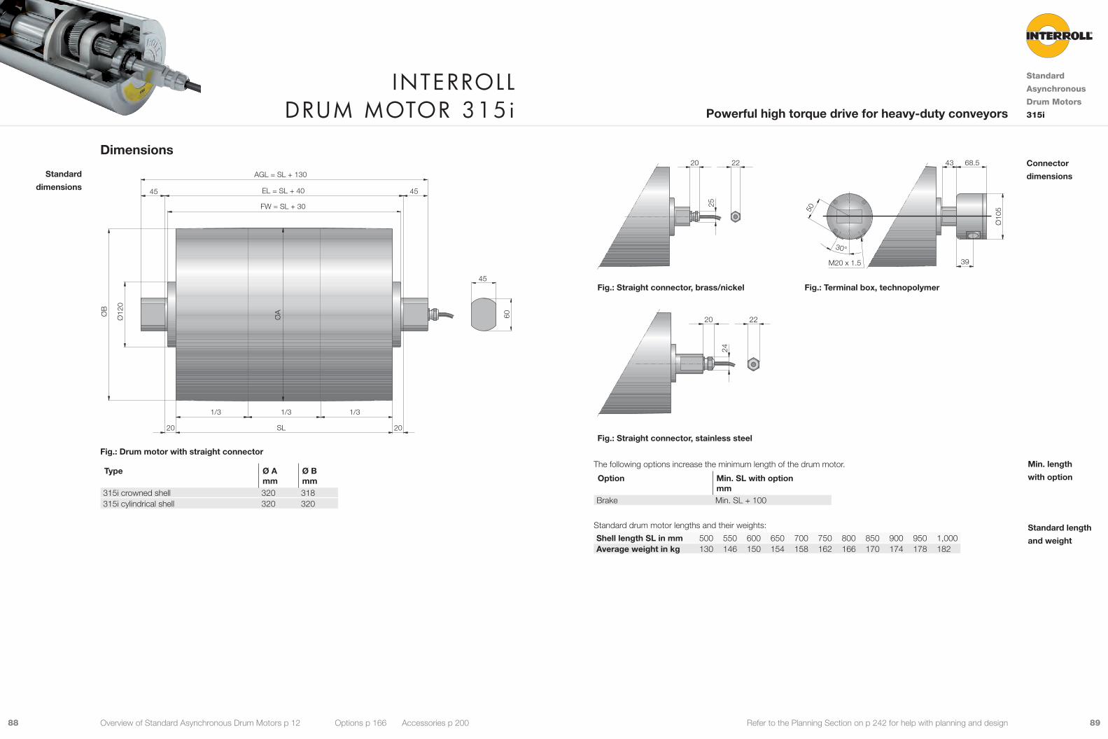
8988 Refer to the Planning Section on p 242 for help with planning and design
20 22
25
50
30°
39
68.543
Ø10
5
M20 x 1.5
Fig.: Straight connector, brass/nickel Fig.: Terminal box, technopolymer
20
24
22
Fig.: Straight connector, stainless steel
The following options increase the minimum length of the drum motor.
Option Min. SL with option mm
Brake Min. SL + 100
Standard drum motor lengths and their weights:
Shell length SL in mm 500 550 600 650 700 750 800 850 900 950 1,000Average weight in kg 130 146 150 154 158 162 166 170 174 178 182
Connector
dimensions
Min. length
with option
Standard length
and weight
Dimensions
ØB
ØA
Ø12
0
FW = SL + 30
EL = SL + 4045 45
60
45
2020 SL
AGL = SL + 130
1/3 1/3 1/3
Fig.: Drum motor with straight connector
Type Ø Amm
Ø Bmm
315i crowned shell 320 318315i cylindrical shell 320 320
Standard
dimensions
Interroll Drum motor 315i
Standard
Asynchronous
Drum Motors
315iPowerful high torque drive for heavy-duty conveyors
Overview of Standard Asynchronous Drum Motors p 12 Options p 166 Accessories p 200

9190 Refer to the Planning Section on p 242 for help with planning and design
o v e r v I e W o f C o o l - r u n n I n G a sy n C h r o n o u s D r u m m oto r s
80i - derated 113i - derated 138i - derated 165i - derated 216i - derated
Diameter 81.5 mm 113.5 mm 138.0 mm 164.0 mm 217.5 mm
Gear material Steel Steel Steel Steel Steel
Rated power 0.033 to 0.099 kW 0.066 to 0.306 kW 0.074 to 0.826 kW 0.306 to 1.818 kW 0.306 to 0.909 kW
Rated torque 2.3 to 21.8 Nm 7.4 to 72.9 Nm 14.7 to 143 Nm 28.1 to 301.9 Nm 28.1 to 301.8 Nm
Belt pull* 58 to 538 N 133 to 1,302 N 216 to 2,103 N 347 to 3,727 N 261 to 2802 N
Velocity of the shell*
0.107 to 0.965 m/s 0.048 to 1.515 m/s 0.041 to 2.012 m/s 0.083 to 2.514 m/s 0.111 to 3.344 m/s
Shell length SL 193 to 943 mm 250 to 1,200 mm 300 to 1,600 mm 400 to 1,600 mm 400 to 1,600 mm
Positive drive belt 9 9 9 9 9
Without belt 9 9 9 9 9
see p 92 see p 98 see p 108 see p 118 see p 128
Cool-Running
Asynchronous
Drum Motors
Overview
Standard Asynchronous Drum Motors p 12 Synchronous Drum Motors p 140 Options p 166 Accessories p 200
Cool-Running Drum Motors are derated to prevent thermal overload. Instead of a Cool-Running Drum Motor you may
use a Standard Drum Motor with frequency converter.
Note: *Values given for cylindrical shell.

9392 Refer to the Planning Section on p 242 for help with planning and design
Material VersionsYou can choose the following versions of drum body components and electrical connection. The versions depend
on the material of the components.
Component Version Material
Aluminium Mild steel
Stainless steel
Brass / Nickel
Techno-polymer
Shell Crowned 9 9Cylindrical 9 9Cylindrical + key, for using sprockets 9 9Special crowns and grooves 9 9
End housing Standard 9 9With V-grooves 9With O-grooves 9With chain sprockets 9 9
Shaft Standard 9Cross-drilled and threaded, M6 9
External seal Galvanised labyrinth 9Labyrinth 9Labyrinth with FPM 9
Electrical connector
Straight connector (for cables see p 300) 9 9 9Elbow connector (for cables see p 300) 9 9
Please contact your Interroll customer consultant for further versions.
Options• Lagging for plastic modular belts, see p 174
• Lagging for positive drive solid homogeneous
belts, see p 178
• Sprockets for plastic modular belts, see p 180
• Backstops, see p 188
• Balancing, see p 189
• Electromagnetic brakes, see p 190
• Rectifiers, see p 194
• Encoders, see p 196
• Food-grade oil (FDA), see p 302
• Low temperature oil, see p 302
• cULus safety certifications, see p 301
• Non-horizontal mounting (more than ± 5°), see p 280
Note: Combination of encoder and electromagnetic brake is not possible.
Accessories• Mounting brackets, see p 204
• Idler pulleys, see p 218 to p 230
• Drive pulleys, see p 230
• Conveyor rollers, see p 232
Product DescriptionThis cool-running drum motor is suitable for positive drive belts, like plastic modular belts or positive drive solid
homogeneous belts. It is also suitable for non-belt applications.
9 Small feed conveyors with high-duty cycles
9 Packaging equipment
9 Dynamic weighing equipment
9 Metal detectors
9 Pharmaceutical handling
9 Food processing
9 Steel or plastic modular belt applications
9 Dry, wet and wash-down applications
9 Salt-water-resistant aluminium bearing housings
9 3-phase AC induction motor
9 Dual voltage
9 Integral motor protection
9 Steel-hardened helical spur gear
9 Low noise
9 Maintenance-free
9 Lifetime lubricated
9 Reversible
9 Reinforced shaft for SL above 543 mm
Note: When using a frequency converter please choose a standard drum motor.
Technical DataElectrical data
Motor type Asynchronous squirrel cage motor, IEC 34 (VDE 0530)Insulation class of motor windings Class F, IEC 34 (VDE 0530)Voltage 230/400 V ±5 % (IEC 34/38)
Special voltage on requestFrequency 50/60 HzInternal shaft sealing system Double-lipped, FPM or NBRProtection rate IP66Thermal protection (see p 302) Bi-metal switchOperation mode (see p 279) S1Ambient temperature, 3-phase motor (see p 263) +5 to +25 °C
General technical data Max. shell length SL 943 mm
All data and values in this catalogue refer to 50 Hz operation.
Order InformationPlease refer to the order information at the end of the catalogue.
Applications
Characteristics
Interroll Drum motor 80i – DerateD
Cool-Running
Drum Motors
80i – derated
Compact and robust drive for small feed conveyors with high-duty cycles
Overview of Cool-Running Drum Motors p 90 Options p 166 Accessories p 200

9594 Refer to the Planning Section on p 242 for help with planning and design
Electrical data for 3-phase motors, derated
PN np UN IN cos φ η JR IS/IN MS/MN MP/MN MB/MN RM USH delta USH star
kW V A kgcm2 Ω V DC V DC0.033 4 230 0.30 0.62 0.45 0.4 1.7 2.73 2.48 2.74 286.5 27 -
400 0.17 0.62 0.45 0.4 1.7 2.73 2.48 2.74 286.5 - 450.058 4 230 0.39 0.68 0.54 0.6 2.4 2.31 2.15 2.31 106.4 14 -
400 0.23 0.68 0.54 0.6 2.4 2.31 2.15 2.31 106.4 - 252 230 0.26 0.78 0.71 0.4 2.4 2.15 1.90 2.26 183.5 19 -
400 0.15 0.78 0.71 0.4 2.4 2.15 1.90 2.26 183.5 - 320.099 2 230 0.45 0.78 0.71 0.6 2.4 2.31 2.15 2.31 106.4 19 -
400 0.26 0.78 0.71 0.6 2.4 2.31 2.15 2.31 106.4 - 32
PN Rated powernp Number of polesUN Rated voltageIN Rated currentcos φ Power factorη EfficiencyJR Rotor moment of inertiaIS/IN Ratio of starting current to rated currentMS/MN Ratio of starting torque to rated torqueMP/MN Ratio of pull-up torque to rated torqueMB/MN Ratio of break-down torque to rated torqueRM Phase resistanceUSH delta Preheating voltage in delta connectionUSH star Preheating voltage in star connection
Cable SpecificationsAvailable cables for connectors (see also p 300):
• Standard, screened
• Standard, unscreened
• Halogen-free, screened
• Halogen-free, unscreened
Available length: 1 / 3 / 5 / 10 m
Connection DiagramsFor connection diagrams, see Planning Section on p 307.
Product RangeThe following tables give an overview of the possible motor versions. When ordering, please specify the version in
accordance with the configurator at the end of the catalogue.
Mechanical data for 3-phase motors, derated
PN np gs i v nA MA FN TE SLmin App.
kW m/s min-1 Nm N N mm 0.033 4 3 54.73 0.107 25.3 11.8 293 3,250 193 û
38.18 0.154 36.2 8.3 204 3,250 193 û31.09 0.189 44.5 6.7 166 3,250 193 û
2 21.28 0.276 65.0 4.7 116 3,250 193 û14.85 0.395 93.2 3.3 81 3,250 193 û12.09 0.486 114.5 2.7 66 3,250 193 û
0.058 4 3 54.73 0.102 23.9 21.8 538 3,250 243 938.18 0.146 34.3 15.2 375 3,250 243 931.09 0.179 42.1 12.4 306 3,250 243 9
2 21.28 0.261 61.6 8.6 213 3,250 243 914.85 0.374 88.2 6.0 149 3,250 243 912.09 0.460 108.3 4.9 121 3,250 243 9
2 3 54.73 0.210 50.2 10.4 256 3,250 193 954.73 0.213 50.2 10.4 256 3,250 193 938.18 0.306 72.0 7.2 178 3,250 193 931.09 0.375 88.5 5.9 145 3,250 193 9
2 21.28 0.548 129.2 4.1 101 3,250 193 914.85 0.786 185.2 2.9 71 3,250 193 912.09 0.965 227.4 2.3 58 3,250 193 9
0.099 2 3 54.73 0.211 49.8 17.9 441 3,250 243 938.18 0.303 71.4 12.5 308 3,250 243 931.09 0.372 87.7 10.2 251 3,250 243 9
2 21.28 0.543 128.1 7.1 175 3,250 243 914.85 0.779 183.7 4.9 122 3,250 243 912.09 0.957 225.5 4.0 99 3,250 243 9
PN Rated powernp Number of polesgs Gear stagesi Gear ratiov Rated velocity of the shellnA Rated revolutions of the shellMA Rated torque of drum motorFN Rated belt pull of drum motorTE Max. belt tensionSLmin Min. shell lengthApp. 9: Suitable for all applications. This version will ensure lowest cost and fast delivery
û: Not suitable for all applications. Please contact your Interroll customer consultant
Motor versions
Interroll Drum motor 80i – DerateD
Cool-Running
Drum Motors
80i – derated
Compact and robust drive for small feed conveyors with high-duty cycles
Overview of Cool-Running Drum Motors p 90 Options p 166 Accessories p 200
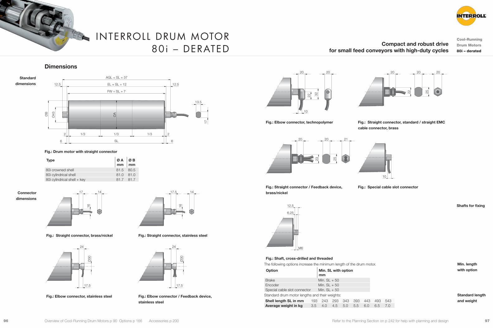
9796 Refer to the Planning Section on p 242 for help with planning and design
22 32
10
20 20
22 25
20 20 20
Fig.: Elbow connector, technopolymer Fig.: Straight connector, standard / straight EMC
cable connector, brass
23 25
20 20 21
10
Fig.: Straight connector / Feedback device,
brass/nickel
Fig.: Special cable slot connector
6.25
M6
12.5
Fig.: Shaft, cross-drilled and threaded
The following options increase the minimum length of the drum motor.
Option Min. SL with option mm
Brake Min. SL + 50Encoder Min. SL + 50Special cable slot connector Min. SL + 50
Standard drum motor lengths and their weights:
Shell length SL in mm 193 243 293 343 393 443 493 543Average weight in kg 3.5 4.0 4.5 5.0 5.5 6.0 6.5 7.0
Shafts for fixing
Min. length
with option
Standard length
and weight
Dimensions
6
2 2
12.512.5
6
1/3 1/3 1/3
13.5
EL = SL + 12
FW = SL + 7
AGL = SL + 37
SL
ØA
ØB
Ø43
17
Fig.: Drum motor with straight connector
Type Ø Amm
Ø Bmm
80i crowned shell 81.5 80.580i cylindrical shell 81.0 81.080i cylindrical shell + key 81.7 81.7
16
17 14
16
17.5 14
Fig.: Straight connector, brass/nickel Fig.: Straight connector, stainless steel
Ø30
17.5
24
Ø30
17.5
24
Fig.: Elbow connector, stainless steel Fig.: Elbow connector / Feedback device,
stainless steel
Standard
dimensions
Connector
dimensions
Interroll Drum motor 80i – DerateD
Cool-Running
Drum Motors
80i – derated
Compact and robust drive for small feed conveyors with high-duty cycles
Overview of Cool-Running Drum Motors p 90 Options p 166 Accessories p 200

9998 Refer to the Planning Section on p 242 for help with planning and design
Material VersionsYou can choose the following versions of drum body components and electrical connection. The versions depend
on the material of the components.
Component Version Material
Aluminium Mild steel
Stainless steel
Brass / Nickel
Techno-polymer
Shell Crowned 9 9Cylindrical 9 9Cylindrical + key, for using sprockets 9 9Special crowns and grooves 9 9
End housing Standard 9 9With V-grooves 9With O-grooves 9With chain sprockets 9 9
Shaft Standard 9 9Cross-drilled thread, M8 9 9
External seal Galvanised labyrinth 9Labyrinth 9Labyrinth with FPM 9
Electrical connector
Straight connector (for cables see p 300) 9 9 9
Elbow connector (for cables see p 300) 9 9Terminal box 9 9 9
Please contact your Interroll customer consultant for further versions.
Options• Lagging for plastic modular belts, see p 174
• Lagging for positive drive solid homogeneous
belts, see p 178
• Sprockets for plastic modular belts, see p 180
• Backstops, see p 188
• Balancing, see p 189
• Electromagnetic brakes, see p 190
• Rectifiers, see p 194
• Encoders, see p 196
• Food-grade oil (FDA), see p 302
• Low temperature oil, see p 302
• cULus safety certifications, see p 301
• Non-horizontal mounting (more than ± 5°), see p 280
Note: Combination of encoder and electromagnetic brake is not possible.
Accessories• Mounting brackets, see p 204
• Idler pulleys, see p 218 to p 230
• Drive pulleys, see p 230
• Conveyor rollers, see p 232
Product DescriptionThis cool-running drum motor is suitable for positive drive belts, like plastic modular belts or positive drive solid
homogeneous belts. It is also suitable for non-belt applications.
9 Small conveyors with high-duty cycles
9 Airport check-in conveyors
9 Packaging equipment
9 Dynamic weighing equipment
9 Metal detectors
9 Pharmaceutical handling
9 Food processing
9 Steel or plastic modular belt applications
9 Dry, wet and wash-down applications
9 Salt-water-resistant aluminium bearing housings
9 3-phase AC induction motor
9 Dual voltage
9 Integral motor protection
9 Steel-hardened helical spur gear
9 Low noise
9 Maintenance-free
9 Lifetime lubricated
9 Reversible
9 Reinforced shaft for SL above 850 mm
Note: When using a frequency converter please choose a standard drum motor.
Technical DataElectrical data
Motor type Asynchronous squirrel cage motor, IEC 34 (VDE 0530)Insulation class of motor windings Class F, IEC 34 (VDE 0530)Voltage 230/400 V ±5 % (IEC 34/38)
Special voltage on requestFrequency 50/60 HzInternal shaft sealing system Double-lipped, FPM or NBRProtection rate IP66Thermal protection (see p 302) Bi-metal switchOperation mode (see p 279) S1Ambient temperature, 3-phase motor (see p 263) +5 to +25 °C
General technical data Max. shell length SL 1,200 mm
All data and values in this catalogue refer to 50 Hz operation.
Order InformationPlease refer to the order information at the end of the catalogue.
Applications
Characteristics
Interroll Drum motor 113i – DerateD
Cool-Running
Drum Motors
113i – deratedPower packed drive for small conveyors with high-duty cycles
Overview of Cool-Running Drum Motors p 90 Options p 166 Accessories p 200
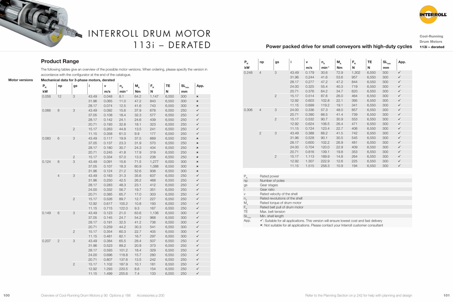
101100 Refer to the Planning Section on p 242 for help with planning and design
PN np gs i v nA MA FN TE SLmin App.
kW m/s min-1 Nm N N mm 0.248 4 3 43.49 0.179 30.6 72.9 1,302 6,550 300 9
31.96 0.244 41.6 53.6 957 6,550 300 928.17 0.277 47.2 47.2 844 6,550 300 924.00 0.325 55.4 40.3 719 6,550 300 920.71 0.376 64.2 34.7 620 6,550 300 9
2 15.17 0.514 87.6 26.0 464 6,550 300 912.92 0.603 102.8 22.1 395 6,550 300 911.15 0.699 119.2 19.1 341 6,550 300 9
0.306 4 3 24.00 0.336 57.3 48.0 857 6,550 300 920.71 0.390 66.5 41.4 739 6,550 300 9
2 15.17 0.532 90.7 30.9 553 6,550 300 912.92 0.624 106.5 26.4 471 6,550 300 911.15 0.724 123.4 22.7 406 6,550 300 9
2 3 43.49 0.388 66.2 41.5 742 6,550 300 931.96 0.528 90.1 30.5 545 6,550 300 928.17 0.600 102.2 26.9 481 6,550 300 924.00 0.704 120.0 22.9 409 6,550 300 920.71 0.816 139.1 19.8 353 6,550 300 9
2 15.17 1.113 189.9 14.8 264 6,550 300 912.92 1.307 222.9 12.6 225 6,550 300 911.15 1.515 258.3 10.9 194 6,550 300 9
PN Rated powernp Number of polesgs Gear stagesi Gear ratiov Rated velocity of the shellnA Rated revolutions of the shellMA Rated torque of drum motorFN Rated belt pull of drum motorTE Max. belt tensionSLmin Min. shell lengthApp. 9: Suitable for all applications. This version will ensure lowest cost and fast delivery
û: Not suitable for all applications. Please contact your Interroll customer consultant
Product RangeThe following tables give an overview of the possible motor versions. When ordering, please specify the version in
accordance with the configurator at the end of the catalogue.
Mechanical data for 3-phase motors, derated
PN np gs i v nA MA FN TE SLmin App.
kW m/s min-1 Nm N N mm 0.058 12 3 43.49 0.048 8.1 64.2 1,147 6,550 300 û
31.96 0.065 11.0 47.2 843 6,550 300 û28.17 0.074 12.5 41.6 743 6,550 300 û
0.066 8 3 43.49 0.092 15.6 37.9 678 6,550 250 937.05 0.108 18.4 32.3 577 6,550 250 928.17 0.142 24.1 24.6 439 6,550 250 920.71 0.193 32.8 18.1 323 6,550 250 9
2 15.17 0.263 44.8 13.5 241 6,550 250 911.15 0.358 61.0 9.9 177 6,550 250 9
0.083 6 3 43.49 0.117 19.9 37.5 669 6,550 250 û37.05 0.137 23.3 31.9 570 6,550 250 û28.17 0.180 30.7 24.3 434 6,550 250 û20.71 0.245 41.8 17.9 319 6,550 250 û
2 15.17 0.334 57.0 13.3 238 6,550 250 û0.124 8 3 43.49 0.091 15.6 71.5 1,277 6,550 300 û
37.05 0.107 18.3 60.9 1,088 6,550 300 û31.96 0.124 21.2 52.6 938 6,550 300 û
4 3 43.49 0.183 31.3 35.6 637 6,550 250 931.96 0.250 42.5 26.2 468 6,550 250 928.17 0.283 48.3 23.1 412 6,550 250 924.00 0.332 56.7 19.7 351 6,550 250 920.71 0.385 65.7 17.0 303 6,550 250 9
2 15.17 0.526 89.7 12.7 227 6,550 250 912.92 0.617 105.2 10.8 193 6,550 250 911.15 0.715 122.0 9.3 167 6,550 250 9
0.149 6 3 43.49 0.123 21.0 63.6 1,136 6,550 300 937.05 0.145 24.7 54.2 968 6,550 300 928.17 0.191 32.5 41.2 736 6,550 300 920.71 0.259 44.2 30.3 541 6,550 300 9
2 15.17 0.354 60.3 22.7 405 6,550 300 911.15 0.481 82.1 16.7 297 6,550 300 9
0.207 2 3 43.49 0.384 65.5 28.4 507 6,550 250 931.96 0.523 89.2 20.9 373 6,550 250 928.17 0.593 101.2 18.4 329 6,550 250 924.00 0.696 118.8 15.7 280 6,550 250 920.71 0.807 137.6 13.5 242 6,550 250 9
2 15.17 1.102 187.9 10.1 181 6,550 250 912.92 1.293 220.5 8.6 154 6,550 250 911.15 1.499 255.6 7.4 133 6,550 250 9
Motor versions
Interroll Drum motor 113i – DerateD
Cool-Running
Drum Motors
113i – deratedPower packed drive for small conveyors with high-duty cycles
Overview of Cool-Running Drum Motors p 90 Options p 166 Accessories p 200
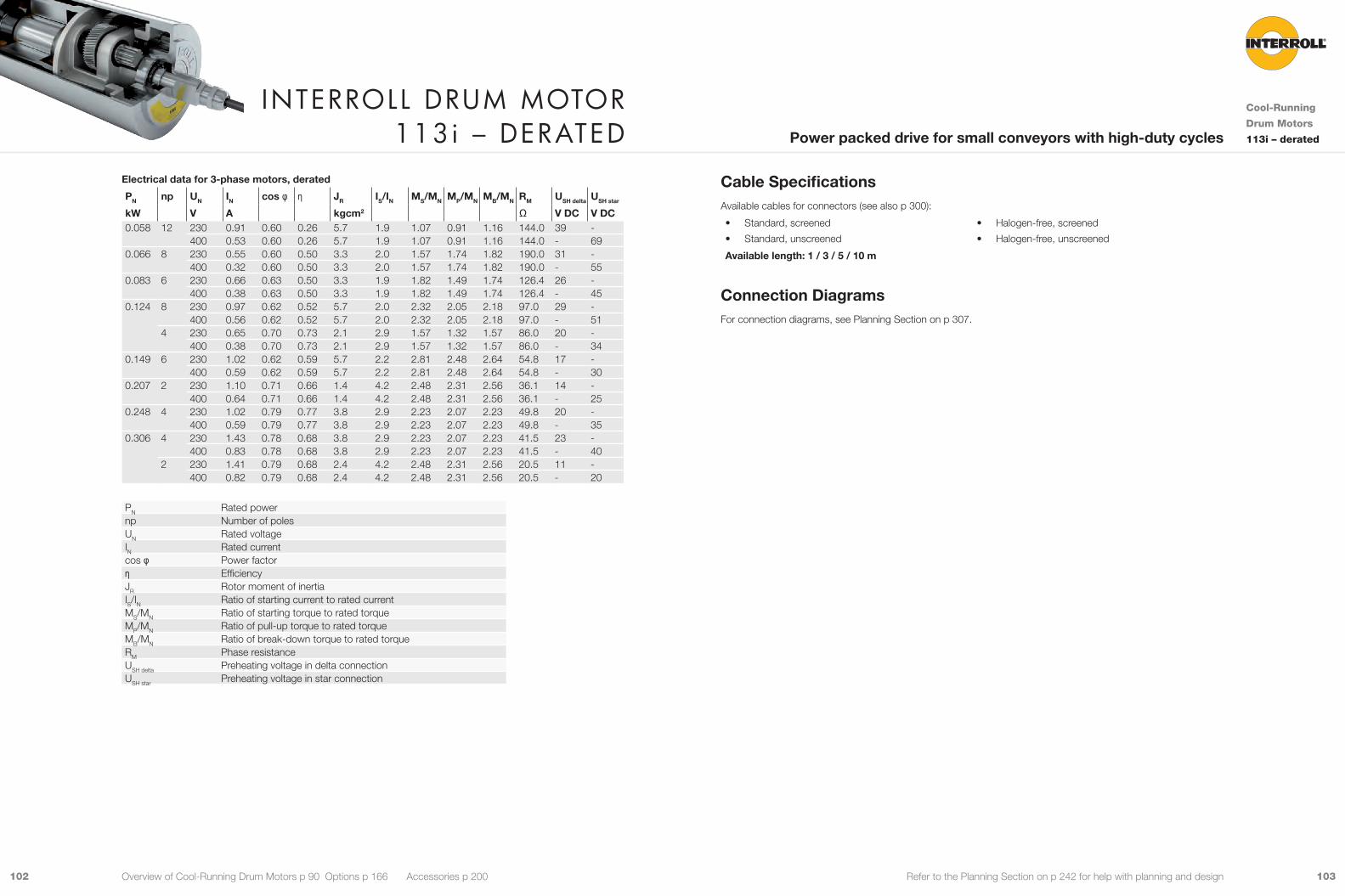
103102 Refer to the Planning Section on p 242 for help with planning and design
Cable SpecificationsAvailable cables for connectors (see also p 300):
• Standard, screened
• Standard, unscreened
• Halogen-free, screened
• Halogen-free, unscreened
Available length: 1 / 3 / 5 / 10 m
Connection DiagramsFor connection diagrams, see Planning Section on p 307.
Electrical data for 3-phase motors, derated
PN np UN IN cos φ η JR IS/IN MS/MN MP/MN MB/MN RM USH delta USH star
kW V A kgcm2 Ω V DC V DC0.058 12 230 0.91 0.60 0.26 5.7 1.9 1.07 0.91 1.16 144.0 39 -
400 0.53 0.60 0.26 5.7 1.9 1.07 0.91 1.16 144.0 - 690.066 8 230 0.55 0.60 0.50 3.3 2.0 1.57 1.74 1.82 190.0 31 -
400 0.32 0.60 0.50 3.3 2.0 1.57 1.74 1.82 190.0 - 550.083 6 230 0.66 0.63 0.50 3.3 1.9 1.82 1.49 1.74 126.4 26 -
400 0.38 0.63 0.50 3.3 1.9 1.82 1.49 1.74 126.4 - 450.124 8 230 0.97 0.62 0.52 5.7 2.0 2.32 2.05 2.18 97.0 29 -
400 0.56 0.62 0.52 5.7 2.0 2.32 2.05 2.18 97.0 - 514 230 0.65 0.70 0.73 2.1 2.9 1.57 1.32 1.57 86.0 20 -
400 0.38 0.70 0.73 2.1 2.9 1.57 1.32 1.57 86.0 - 340.149 6 230 1.02 0.62 0.59 5.7 2.2 2.81 2.48 2.64 54.8 17 -
400 0.59 0.62 0.59 5.7 2.2 2.81 2.48 2.64 54.8 - 300.207 2 230 1.10 0.71 0.66 1.4 4.2 2.48 2.31 2.56 36.1 14 -
400 0.64 0.71 0.66 1.4 4.2 2.48 2.31 2.56 36.1 - 250.248 4 230 1.02 0.79 0.77 3.8 2.9 2.23 2.07 2.23 49.8 20 -
400 0.59 0.79 0.77 3.8 2.9 2.23 2.07 2.23 49.8 - 350.306 4 230 1.43 0.78 0.68 3.8 2.9 2.23 2.07 2.23 41.5 23 -
400 0.83 0.78 0.68 3.8 2.9 2.23 2.07 2.23 41.5 - 402 230 1.41 0.79 0.68 2.4 4.2 2.48 2.31 2.56 20.5 11 -
400 0.82 0.79 0.68 2.4 4.2 2.48 2.31 2.56 20.5 - 20
PN Rated powernp Number of polesUN Rated voltageIN Rated currentcos φ Power factorη EfficiencyJR Rotor moment of inertiaIS/IN Ratio of starting current to rated currentMS/MN Ratio of starting torque to rated torqueMP/MN Ratio of pull-up torque to rated torqueMB/MN Ratio of break-down torque to rated torqueRM Phase resistanceUSH delta Preheating voltage in delta connectionUSH star Preheating voltage in star connection
Interroll Drum motor 113i – DerateD
Cool-Running
Drum Motors
113i – deratedPower packed drive for small conveyors with high-duty cycles
Overview of Cool-Running Drum Motors p 90 Options p 166 Accessories p 200

105104 Refer to the Planning Section on p 242 for help with planning and design
Dimensions
ØB
ØA
Ø83
FW = SL + 10.6
EL = SL + 2025 25
25
20
1010
1.51.5
SL
AGL = SL + 70
1/3 1/3 1/3
Fig.: Drum motor with straight connector
Type Ø Amm
Ø Bmm
113i crowned shell 113.5 112.0113i cylindrical shell 112.0 112.0113i cylindrical shell + key 113.0 113.0
22
20 21
24
20 22
Fig.: Straight connector, brass/nickel Fig.: Straight connector, stainless steel
Standard
dimensions
Connector
dimensions
20
1.5
22
20 20
Fig.: Straight cable outlet, PU shaft plug Fig.: Straight connector, standard / straight EMC
cable connector, brass
23
20 21
22 32
10
20 20
Fig.: Straight connector / Feedback device,
brass/nickel
Fig.: Elbow connector, technopolymer
Ø30
17.5
24
Ø30
17.5
24
Fig.: Elbow connector, stainless steel Fig.: Elbow connector / Feedback device,
stainless steel
Interroll Drum motor 113i – DerateD
Cool-Running
Drum Motors
113i – deratedPower packed drive for small conveyors with high-duty cycles
Overview of Cool-Running Drum Motors p 90 Options p 166 Accessories p 200

107106 Refer to the Planning Section on p 242 for help with planning and design
47
20° 25
4323
Ø99
14
M20 x 1.5
50
30° 39
72
Ø10
5
M20 x 1.5
23
Fig.: Terminal box, stainless steel Fig.: Terminal box, technopolymer
65
17 22
4623
Ø95
14
M20 x 1.56.5
Fig.: Terminal box, aluminium Fig.: Special cable slot connector
25
M8
12.5
Fig.: Shaft, cross-drilled and threaded
Shafts for fixing
The following options increase the minimum length of the drum motor.
Option Min. SL with option mm
Brake Min. SL + 50Encoder Min. SL + 50Special cable slot connector Min. SL + 50
Standard drum motor lengths and their weights:
Shell length SL in mm 250 300 350 400 450 500 550 600 650 700 750 800 850Average weight in kg 8.5 9.15 9.8 10.5 11.1 11.75 12.4 13.05 13.7 14.35 15.0 15.65 16.3
Min. length
with option
Standard length
and weight
Interroll Drum motor 113i – DerateD
Cool-Running
Drum Motors
113i – deratedPower packed drive for small conveyors with high-duty cycles
Overview of Cool-Running Drum Motors p 90 Options p 166 Accessories p 200
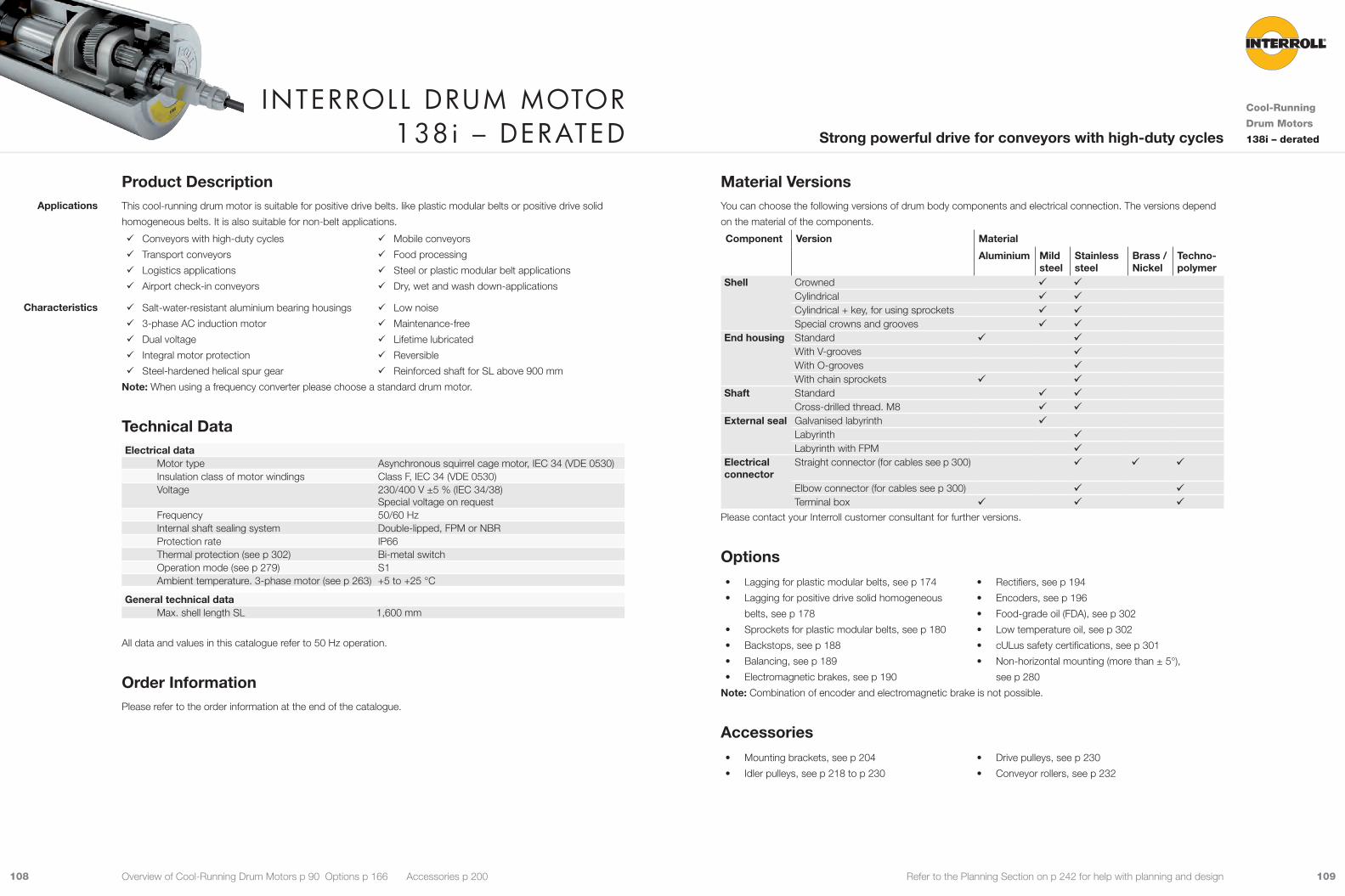
109108 Refer to the Planning Section on p 242 for help with planning and design
Material VersionsYou can choose the following versions of drum body components and electrical connection. The versions depend
on the material of the components.
Component Version Material
Aluminium Mild steel
Stainless steel
Brass / Nickel
Techno-polymer
Shell Crowned 9 9Cylindrical 9 9Cylindrical + key, for using sprockets 9 9Special crowns and grooves 9 9
End housing Standard 9 9With V-grooves 9With O-grooves 9With chain sprockets 9 9
Shaft Standard 9 9Cross-drilled thread. M8 9 9
External seal Galvanised labyrinth 9Labyrinth 9Labyrinth with FPM 9
Electrical connector
Straight connector (for cables see p 300) 9 9 9
Elbow connector (for cables see p 300) 9 9Terminal box 9 9 9
Please contact your Interroll customer consultant for further versions.
Options• Lagging for plastic modular belts, see p 174
• Lagging for positive drive solid homogeneous
belts, see p 178
• Sprockets for plastic modular belts, see p 180
• Backstops, see p 188
• Balancing, see p 189
• Electromagnetic brakes, see p 190
• Rectifiers, see p 194
• Encoders, see p 196
• Food-grade oil (FDA), see p 302
• Low temperature oil, see p 302
• cULus safety certifications, see p 301
• Non-horizontal mounting (more than ± 5°),
see p 280
Note: Combination of encoder and electromagnetic brake is not possible.
Accessories• Mounting brackets, see p 204
• Idler pulleys, see p 218 to p 230
• Drive pulleys, see p 230
• Conveyor rollers, see p 232
Product DescriptionThis cool-running drum motor is suitable for positive drive belts. like plastic modular belts or positive drive solid
homogeneous belts. It is also suitable for non-belt applications.
9 Conveyors with high-duty cycles
9 Transport conveyors
9 Logistics applications
9 Airport check-in conveyors
9 Mobile conveyors
9 Food processing
9 Steel or plastic modular belt applications
9 Dry, wet and wash down-applications
9 Salt-water-resistant aluminium bearing housings
9 3-phase AC induction motor
9 Dual voltage
9 Integral motor protection
9 Steel-hardened helical spur gear
9 Low noise
9 Maintenance-free
9 Lifetime lubricated
9 Reversible
9 Reinforced shaft for SL above 900 mm
Note: When using a frequency converter please choose a standard drum motor.
Technical DataElectrical data
Motor type Asynchronous squirrel cage motor, IEC 34 (VDE 0530)Insulation class of motor windings Class F, IEC 34 (VDE 0530)Voltage 230/400 V ±5 % (IEC 34/38)
Special voltage on requestFrequency 50/60 HzInternal shaft sealing system Double-lipped, FPM or NBRProtection rate IP66Thermal protection (see p 302) Bi-metal switchOperation mode (see p 279) S1Ambient temperature. 3-phase motor (see p 263) +5 to +25 °C
General technical data Max. shell length SL 1,600 mm
All data and values in this catalogue refer to 50 Hz operation.
Order InformationPlease refer to the order information at the end of the catalogue.
Applications
Characteristics
Interroll Drum motor 138i – DerateD
Cool-Running
Drum Motors
138i – deratedStrong powerful drive for conveyors with high-duty cycles
Overview of Cool-Running Drum Motors p 90 Options p 166 Accessories p 200

111110 Refer to the Planning Section on p 242 for help with planning and design
PN np gs i v nA MA FN TE SLmin App.
kW m/s min-1 Nm N N mm 0.620 4 3 34.00 0.292 41.0 134.8 1,983 8,300 350 9
30.55 0.325 45.7 121.1 1,781 8,300 350 925.39 0.391 55.0 101.0 1,485 8,300 350 9
2 20.22 0.491 69.0 81.2 1,194 8,300 350 916.67 0.596 83.7 67.4 992 8,300 350 912.44 0.798 112.1 50.5 743 8,300 350 910.00 0.993 139.5 40.6 597 8,300 350 9
0.826 2 3 49.64 0.396 55.6 131.4 1,932 8,300 350 940.91 0.481 67.5 109.2 1,606 8,300 350 934.00 0.579 81.2 90.7 1,334 8,300 350 925.39 0.775 108.8 68.0 999 8,300 350 9
2 20.22 0.973 136.6 54.6 803 8,300 350 916.67 1.180 165.7 45.4 667 8,300 350 912.44 1.581 221.9 34.0 500 8,300 350 910.00 1.967 276.2 27.3 402 8.300 350 9
PN Rated powernp Number of polesgs Gear stagesi Gear ratiov Rated velocity of the shellnA Rated revolutions of the shellMA Rated torque of drum motorFN Rated belt pull of drum motorTE Max. belt tensionSLmin Min. shell lengthApp. 9: Suitable for all applications. This version will ensure lowest cost and fast delivery
û: Not suitable for all applications. Please contact your Interroll customer consultant
Product RangeThe following tables give an overview of the possible motor versions. When ordering, please specify the version in
accordance with the configurator at the end of the catalogue.
Mechanical data for 3-phase motors, derated
PN np gs i v nA MA FN TE SLmin App.
kW m/s min-1 Nm N N mm 0.074 12 3 72.55 0.041 5.7 112.5 1,654 8,300 300 û
49.64 0.060 8.4 78.3 1,152 8,300 300 û40.91 0.072 10.1 65.1 957 8,300 300 û30.55 0.097 13.6 48.6 715 8,300 300 û
0.149 8 3 72.55 0.067 9.4 137.4 2,020 8,300 300 949.64 0.098 13.8 95.7 1,407 8,300 300 940.91 0.119 16.7 79.5 1,169 8,300 300 930.55 0.160 22.4 59.4 873 8,300 300 925.39 0.192 26.9 49.5 728 8,300 300 9
2 20.22 0.241 33.8 39.8 585 8,300 300 916.67 0.292 41.0 33.1 486 8,300 300 9
0.207 6 3 72.55 0.090 12.7 141.9 2,087 8,300 300 949.64 0.132 18.5 98.9 1,454 8,300 300 940.91 0.160 22.5 82.2 1,208 8,300 300 934.00 0.193 27.1 68.3 1,004 8,300 300 930.55 0.215 30.1 61.3 902 8,300 300 925.39 0.258 36.2 51.1 752 8,300 300 9
2 20.22 0.324 45.5 41.1 604 8,300 300 916.67 0.393 55.2 34.2 502 8,300 300 912.44 0.526 73.9 25.6 376 8,300 300 9
0.306 4 3 72.55 0.133 18.6 143.0 2,103 8,300 300 949.64 0.194 27.2 99.6 1,465 8,300 300 940.91 0.235 33.0 82.8 1,217 8,300 300 934.00 0.283 39.7 68.8 1,012 8,300 300 930.55 0.315 44.2 61.8 909 8,300 300 925.39 0.379 53.2 51.5 758 8,300 300 9
2 20.22 0.475 66.8 41.4 609 8,300 300 916.67 0.577 81.0 34.4 506 8,300 300 912.44 0.773 108.5 25.8 379 8,300 300 9
0.455 2 3 72.55 0.277 39.0 101.6 1,494 8,300 300 961.85 0.325 45.7 87.4 1,286 8,300 300 949.64 0.405 56.9 70.8 1,040 8,300 300 940.91 0.492 69.1 58.8 865 8,300 300 934.00 0.592 83.1 48.9 719 8,300 300 925.39 0.793 111.3 36.6 538 8,300 300 9
2 20.22 0.995 139.7 29.4 433 8,300 300 916.67 1.207 169.6 24.4 359 8,300 300 912.44 1.617 227.1 18.3 269 8,300 300 910.00 2.012 282.6 14.7 216 8,300 300 9
Motor versions
Interroll Drum motor 138i – DerateD
Cool-Running
Drum Motors
138i – deratedStrong powerful drive for conveyors with high-duty cycles
Overview of Cool-Running Drum Motors p 90 Options p 166 Accessories p 200

113112 Refer to the Planning Section on p 242 for help with planning and design
Cable SpecificationsAvailable cables for connectors (see also p 300):
• Standard, screened
• Standard, unscreened
• Halogen-free, screened
• Halogen-free, unscreened
Available length: 1 / 3 / 5 / 10 m
Connection DiagramsFor connection diagrams, see Planning Section on p 307.
Electrical data for 3-phase motors, derated
PN np UN IN cos φ η JR IS/IN MS/MN MP/MN MB/MN RM USH delta USH star
kW V A kgcm2 Ω V DC V DC0.074 12 230 0.94 0.40 0.49 9.3 2.7 1.16 0.99 1.32 110.0 21 -
400 0.55 0.40 0.49 9.3 2.7 1.16 0.99 1.32 110.0 - 360.149 8 230 0.94 0.64 0.61 9.3 2.4 1.32 1.16 1.40 98.0 29 -
400 0.55 0.64 0.61 9.3 2.4 1.32 1.16 1.40 98.0 - 520.207 6 230 1.10 0.68 0.69 9.3 2.7 1.40 1.24 1.40 47.8 18 -
400 0.64 0.68 0.69 9.3 2.7 1.40 1.24 1.40 47.8 - 310.306 4 230 1.26 0.79 0.77 5.6 3.0 1.34 1.16 1.49 33.1 16 -
400 0.73 0.79 0.77 5.6 3.0 1.34 1.16 1.49 33.1 - 290.455 2 230 2.12 0.72 0.74 3.5 5.0 2.38 1.98 2.56 14.1 11 -
400 1.23 0.72 0.74 3.5 5.0 2.38 1.98 2.56 14.1 - 190.620 4 230 2.66 0.79 0.73 9.9 3.1 1.07 1.40 1.24 11.8 12 -
400 1.55 0.79 0.73 9.9 3.1 1.07 1.40 1.24 11.8 - 220.826 2 230 3.13 0.81 0.81 6.2 4.9 1.90 1.74 2.07 6.8 9 -
400 1.82 0.81 0.81 6.2 4.9 1.90 1.74 2.07 6.8 - 15
PN Rated powernp Number of polesUN Rated voltageIN Rated currentcos φ Power factorη EfficiencyJR Rotor moment of inertiaIS/IN Ratio of starting current to rated currentMS/MN Ratio of starting torque to rated torqueMP/MN Ratio of pull-up torque to rated torqueMB/MN Ratio of break-down torque to rated torqueRM Phase resistanceUSH delta Preheating voltage in delta connectionUSH star Preheating voltage in star connection
Interroll Drum motor 138i – DerateD
Cool-Running
Drum Motors
138i – deratedStrong powerful drive for conveyors with high-duty cycles
Overview of Cool-Running Drum Motors p 90 Options p 166 Accessories p 200

115114 Refer to the Planning Section on p 242 for help with planning and design
Dimensions
ØB
ØAØ10
0
FW = SL + 13
EL = SL + 3025 25
30
20
1515
1.51.5
SL
AGL = SL + 80
1/3 1/3 1/3
Fig.: Drum motor with straight connector
Type Ø Amm
Ø Bmm
138i crowned shell 138.0 136.0138i cylindrical shell 136.0 136.0138i cylindrical shell + key 137.0 137.0
22
20 21
24
20 22
Fig.: Straight connector, brass/nickel Fig.: Straight connector, stainless steel
Standard
dimensions
Connector
dimensions
Interroll Drum motor 138i – DerateD
Cool-Running
Drum Motors
138i – deratedStrong powerful drive for conveyors with high-duty cycles
Overview of Cool-Running Drum Motors p 90 Options p 166 Accessories p 200
20
1.5
22
20 20
Fig.: Straight cable outlet, PU shaft plug Fig.: Straight connector, standard / straight EMC
cable connector, brass
23
20 21
22 32
10
20 20
Fig.: Straight connector / Feedback device,
brass/nickel
Fig.: Elbow connector, technopolymer
Ø30
17.5
24
Ø30
17.5
24
Fig.: Elbow connector, stainless steel Fig.: Elbow connector / Feedback device,
stainless steel
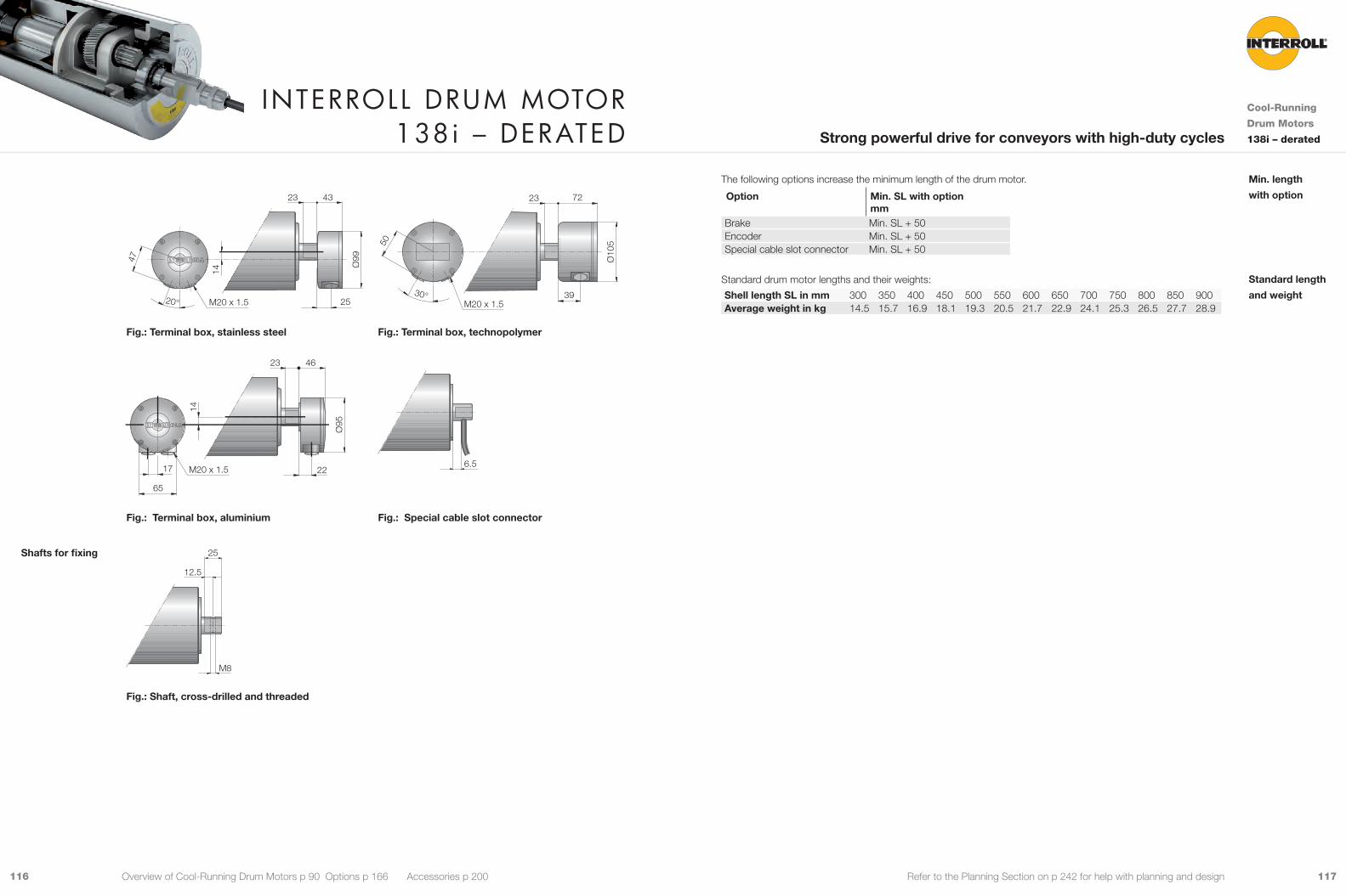
117116 Refer to the Planning Section on p 242 for help with planning and design
47
20° 25
4323
Ø99
14
M20 x 1.5
50
30° 39
72
Ø10
5
M20 x 1.5
23
Fig.: Terminal box, stainless steel Fig.: Terminal box, technopolymer
65
17 22
4623
Ø95
14
M20 x 1.56.5
Fig.: Terminal box, aluminium Fig.: Special cable slot connector
25
M8
12.5
Fig.: Shaft, cross-drilled and threaded
Shafts for fixing
The following options increase the minimum length of the drum motor.
Option Min. SL with option mm
Brake Min. SL + 50Encoder Min. SL + 50Special cable slot connector Min. SL + 50
Standard drum motor lengths and their weights:
Shell length SL in mm 300 350 400 450 500 550 600 650 700 750 800 850 900Average weight in kg 14.5 15.7 16.9 18.1 19.3 20.5 21.7 22.9 24.1 25.3 26.5 27.7 28.9
Min. length
with option
Standard length
and weight
Interroll Drum motor 138i – DerateD
Cool-Running
Drum Motors
138i – deratedStrong powerful drive for conveyors with high-duty cycles
Overview of Cool-Running Drum Motors p 90 Options p 166 Accessories p 200
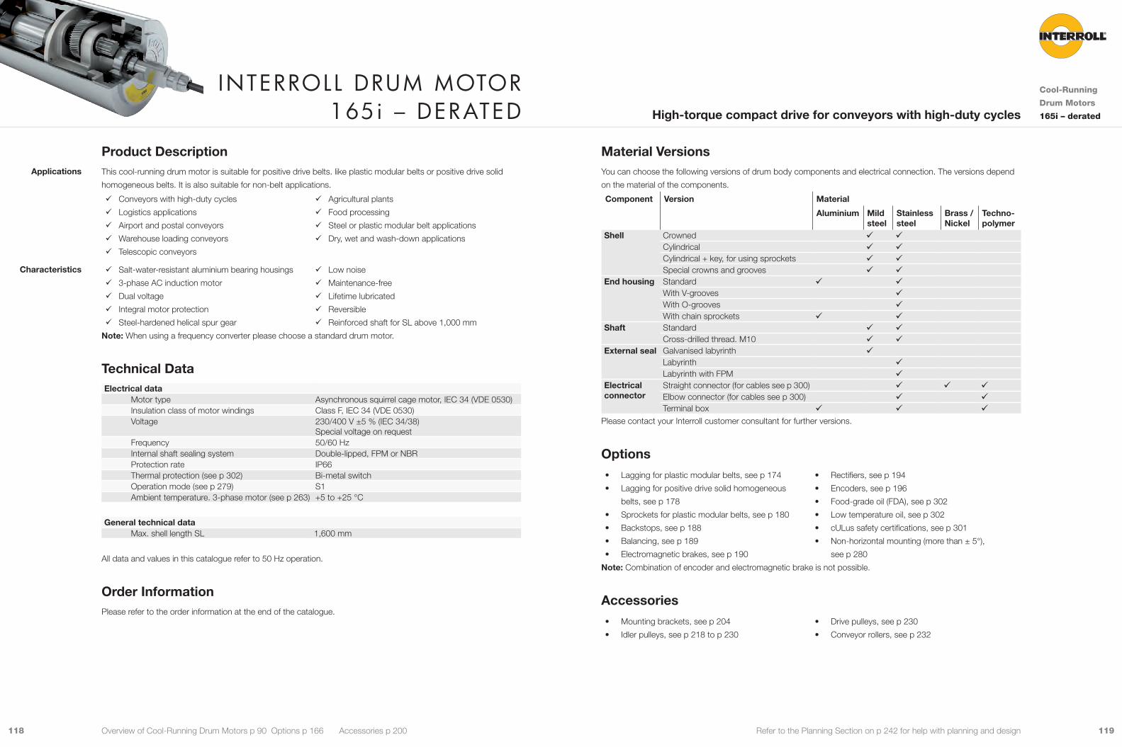
119118 Refer to the Planning Section on p 242 for help with planning and design
Material VersionsYou can choose the following versions of drum body components and electrical connection. The versions depend
on the material of the components.
Component Version Material
Aluminium Mild steel
Stainless steel
Brass / Nickel
Techno-polymer
Shell Crowned 9 9Cylindrical 9 9Cylindrical + key, for using sprockets 9 9Special crowns and grooves 9 9
End housing Standard 9 9With V-grooves 9With O-grooves 9With chain sprockets 9 9
Shaft Standard 9 9Cross-drilled thread. M10 9 9
External seal Galvanised labyrinth 9Labyrinth 9Labyrinth with FPM 9
Electrical connector
Straight connector (for cables see p 300) 9 9 9Elbow connector (for cables see p 300) 9 9Terminal box 9 9 9
Please contact your Interroll customer consultant for further versions.
Options• Lagging for plastic modular belts, see p 174
• Lagging for positive drive solid homogeneous
belts, see p 178
• Sprockets for plastic modular belts, see p 180
• Backstops, see p 188
• Balancing, see p 189
• Electromagnetic brakes, see p 190
• Rectifiers, see p 194
• Encoders, see p 196
• Food-grade oil (FDA), see p 302
• Low temperature oil, see p 302
• cULus safety certifications, see p 301
• Non-horizontal mounting (more than ± 5°),
see p 280
Note: Combination of encoder and electromagnetic brake is not possible.
Accessories• Mounting brackets, see p 204
• Idler pulleys, see p 218 to p 230
• Drive pulleys, see p 230
• Conveyor rollers, see p 232
Product DescriptionThis cool-running drum motor is suitable for positive drive belts. like plastic modular belts or positive drive solid
homogeneous belts. It is also suitable for non-belt applications.
9 Conveyors with high-duty cycles
9 Logistics applications
9 Airport and postal conveyors
9 Warehouse loading conveyors
9 Telescopic conveyors
9 Agricultural plants
9 Food processing
9 Steel or plastic modular belt applications
9 Dry, wet and wash-down applications
9 Salt-water-resistant aluminium bearing housings
9 3-phase AC induction motor
9 Dual voltage
9 Integral motor protection
9 Steel-hardened helical spur gear
9 Low noise
9 Maintenance-free
9 Lifetime lubricated
9 Reversible
9 Reinforced shaft for SL above 1,000 mm
Note: When using a frequency converter please choose a standard drum motor.
Technical DataElectrical data
Motor type Asynchronous squirrel cage motor, IEC 34 (VDE 0530)Insulation class of motor windings Class F, IEC 34 (VDE 0530)Voltage 230/400 V ±5 % (IEC 34/38)
Special voltage on requestFrequency 50/60 HzInternal shaft sealing system Double-lipped, FPM or NBRProtection rate IP66Thermal protection (see p 302) Bi-metal switchOperation mode (see p 279) S1Ambient temperature. 3-phase motor (see p 263) +5 to +25 °C
General technical data Max. shell length SL 1,600 mm
All data and values in this catalogue refer to 50 Hz operation.
Order InformationPlease refer to the order information at the end of the catalogue.
Applications
Characteristics
Interroll Drum motor 165i – DerateD
Cool-Running
Drum Motors
165i – deratedHigh-torque compact drive for conveyors with high-duty cycles
Overview of Cool-Running Drum Motors p 90 Options p 166 Accessories p 200

121120 Refer to the Planning Section on p 242 for help with planning and design
PN np gs i v nA MA FN TE SLmin App.
kW m/s min-1 Nm N N mm 1.818 2 3 46.56 0.519 61.2 267.0 3,296 19,000 450 9
39.31 0.615 72.5 225.4 2,783 19,000 450 931.56 0.766 90.3 180.9 2,234 19,000 450 924.60 0.983 115.9 141.1 1,741 19,000 450 9
2 19.64 1.231 145.1 114.9 1,418 19,000 450 914.66 1.649 194.4 85.8 1,059 19,000 450 912.38 1.954 230.3 72.4 894 19,000 450 99.65 2.505 295.3 56.5 697 19.000 450 9
PN Rated powernp Number of polesgs Gear stagesi Gear ratiov Rated velocity of the shellnA Rated revolutions of the shellMA Rated torque of drum motorFN Rated belt pull of drum motorTE Max. belt tensionSLmin Min. shell lengthApp. 9: Suitable for all applications. This version will ensure lowest cost and fast delivery
û: Not suitable for all applications. Please contact your Interroll customer consultant
Product RangeThe following tables give an overview of the possible motor versions. When ordering, please specify the version in
accordance with the configurator at the end of the catalogue.
Mechanical data for 3-phase motors. derated
PN np gs i v nA MA FN TE SLmin App.
kW m/s min-1 Nm N N mm 0.306 12 3 46.56 0.083 9.8 280.8 3,467 19,000 450 û
8 3 62.37 0.100 13.5 204.2 2,521 19,000 400 939.31 0.181 21.4 128.7 1,589 19,000 400 9
0.455 6 3 62.37 0.115 13.5 301.9 3,727 19,000 400 946.56 0.154 18.1 225.3 2,782 19,000 400 939.31 0.182 21.5 190.2 2,349 19,000 400 9
2 19.64 0.365 43.0 97.0 1,197 19,000 400 914.66 0.489 57.7 72.4 894 19,000 400 912.38 0.579 68.3 61.1 754 19,000 400 9
0.620 6 3 46.56 0.158 18.6 299.9 3,703 19,000 450 939.31 0.187 22.0 253.2 3,126 19,000 450 9
4 3 62.37 0.187 22.1 252.3 3,114 19,000 400 946.56 0.251 29.6 188.3 2,325 19,000 400 939.31 0.297 35.1 159.0 1,963 19,000 400 931.56 0.370 43.7 127.6 1,576 19,000 400 924.60 0.475 56.0 99.5 1,228 19,000 400 9
2 19.64 0.595 70.2 81.0 1,000 19,000 400 914.66 0.798 94.0 60.5 747 19,000 400 912.38 0.945 111.4 51.1 630 19,000 400 9
0.909 4 3 46.56 0.241 28.4 288.2 3,558 19,000 400 939.31 0.285 33.6 243.3 3,004 19,000 400 931.56 0.355 41.8 195.3 2,411 19,000 400 924.60 0.455 53.7 152.3 1,880 19,000 400 9
2 19.64 0.570 67.2 124.0 1,531 19,000 400 914.66 0.764 90.1 92.6 1,143 19,000 400 912.38 0.905 106.7 78.2 965 19,000 400 9
2 3 46.56 0.521 61.4 133.0 1,642 19,000 400 939.31 0.617 72.8 112.3 1,386 19,000 400 931.56 0.769 90.6 90.1 1,113 19,000 400 924.60 0.986 116.3 70.3 868 19,000 400 9
2 19.64 1.235 145.6 57.2 707 19,000 400 914.66 1.655 195.1 42.7 527 19,000 400 912.38 1.960 231.1 36.1 445 19,000 400 99.65 2.514 296.4 28.1 347 19,000 400 9
1.240 4 3 31.56 0.374 44.1 252.5 3,117 19,000 450 924.60 0.480 56.6 196.8 2,430 19,000 450 9
2 19.64 0.602 70.9 160.3 1,979 19,000 450 914.66 0.806 95.0 119.7 1,477 19,000 450 912.38 0.955 112.6 101.0 1,247 19,000 450 9
Motor versions
Interroll Drum motor 165i – DerateD
Cool-Running
Drum Motors
165i – deratedHigh-torque compact drive for conveyors with high-duty cycles
Overview of Cool-Running Drum Motors p 90 Options p 166 Accessories p 200
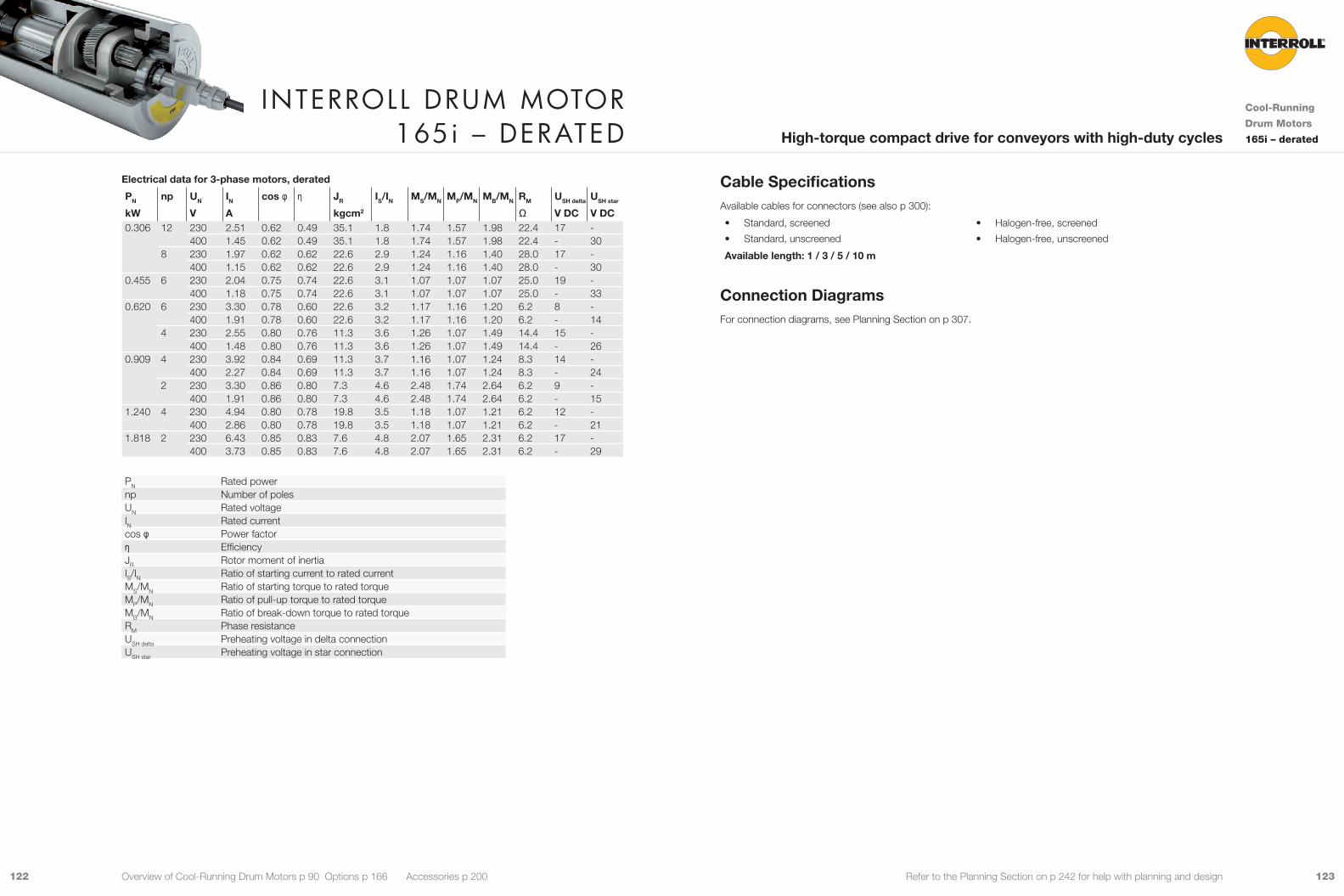
123122 Refer to the Planning Section on p 242 for help with planning and design
Cable SpecificationsAvailable cables for connectors (see also p 300):
• Standard, screened
• Standard, unscreened
• Halogen-free, screened
• Halogen-free, unscreened
Available length: 1 / 3 / 5 / 10 m
Connection DiagramsFor connection diagrams, see Planning Section on p 307.
Electrical data for 3-phase motors, derated
PN np UN IN cos φ η JR IS/IN MS/MN MP/MN MB/MN RM USH delta USH star
kW V A kgcm2 Ω V DC V DC0.306 12 230 2.51 0.62 0.49 35.1 1.8 1.74 1.57 1.98 22.4 17 -
400 1.45 0.62 0.49 35.1 1.8 1.74 1.57 1.98 22.4 - 308 230 1.97 0.62 0.62 22.6 2.9 1.24 1.16 1.40 28.0 17 -
400 1.15 0.62 0.62 22.6 2.9 1.24 1.16 1.40 28.0 - 300.455 6 230 2.04 0.75 0.74 22.6 3.1 1.07 1.07 1.07 25.0 19 -
400 1.18 0.75 0.74 22.6 3.1 1.07 1.07 1.07 25.0 - 330.620 6 230 3.30 0.78 0.60 22.6 3.2 1.17 1.16 1.20 6.2 8 -
400 1.91 0.78 0.60 22.6 3.2 1.17 1.16 1.20 6.2 - 144 230 2.55 0.80 0.76 11.3 3.6 1.26 1.07 1.49 14.4 15 -
400 1.48 0.80 0.76 11.3 3.6 1.26 1.07 1.49 14.4 - 260.909 4 230 3.92 0.84 0.69 11.3 3.7 1.16 1.07 1.24 8.3 14 -
400 2.27 0.84 0.69 11.3 3.7 1.16 1.07 1.24 8.3 - 242 230 3.30 0.86 0.80 7.3 4.6 2.48 1.74 2.64 6.2 9 -
400 1.91 0.86 0.80 7.3 4.6 2.48 1.74 2.64 6.2 - 151.240 4 230 4.94 0.80 0.78 19.8 3.5 1.18 1.07 1.21 6.2 12 -
400 2.86 0.80 0.78 19.8 3.5 1.18 1.07 1.21 6.2 - 211.818 2 230 6.43 0.85 0.83 7.6 4.8 2.07 1.65 2.31 6.2 17 -
400 3.73 0.85 0.83 7.6 4.8 2.07 1.65 2.31 6.2 - 29
PN Rated powernp Number of polesUN Rated voltageIN Rated currentcos φ Power factorη EfficiencyJR Rotor moment of inertiaIS/IN Ratio of starting current to rated currentMS/MN Ratio of starting torque to rated torqueMP/MN Ratio of pull-up torque to rated torqueMB/MN Ratio of break-down torque to rated torqueRM Phase resistanceUSH delta Preheating voltage in delta connectionUSH star Preheating voltage in star connection
Interroll Drum motor 165i – DerateD
Cool-Running
Drum Motors
165i – deratedHigh-torque compact drive for conveyors with high-duty cycles
Overview of Cool-Running Drum Motors p 90 Options p 166 Accessories p 200
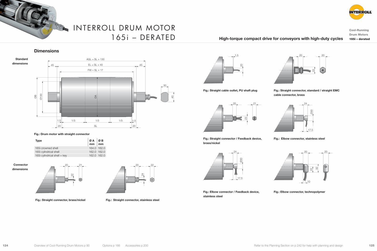
125124 Refer to the Planning Section on p 242 for help with planning and design
Dimensions
ØB
ØA
Ø13
0
FW = SL + 17
EL = SL + 4045 45
40
30
2020
1.51.5
SL
AGL = SL + 130
1/3 1/3 1/3
Fig.: Drum motor with straight connector
Type Ø Amm
Ø Bmm
165i crowned shell 164.0 162.0165i cylindrical shell 162.0 162.0165i cylindrical shell + key 162.0 162.0
20
22
21 20
24
22
Fig.: Straight connector, brass/nickel Fig.: Straight connector, stainless steel
Standard
dimensions
Connector
dimensions
Interroll Drum motor 165i – DerateD
Cool-Running
Drum Motors
165i – deratedHigh-torque compact drive for conveyors with high-duty cycles
Overview of Cool-Running Drum Motors p 90 Options p 166 Accessories p 200
1.5
20
22
20 20
Fig.: Straight cable outlet, PU shaft plug Fig.: Straight connector, standard / straight EMC
cable connector, brass
23
20 21
17.5
24
Ø30
Fig.: Straight connector / Feedback device,
brass/nickel
Fig.: Elbow connector, stainless steel
17.5
24
Ø30
22 32
10
20 20
Fig.: Elbow connector / Feedback device,
stainless steel
Fig.: Elbow connector, technopolymer

127126 Refer to the Planning Section on p 242 for help with planning and design
20
26.5
50
30° 39
7243
Ø10
5
M20 x 1.5
Fig.: Special cable slot connector Fig.: Terminal box, technopolymer
65
17 22
46
Ø95
14
M20 x 1.5
4347
20° 25
4343
Ø99
14
M20 x 1.5
Fig.: Terminal box, aluminium Fig.: Terminal box, stainless steel
M10
12.5
25
Fig.: Shaft, cross-drilled and threaded
For cross-drilled and threaded hole the shaft flat length is reduced from 45 to 25 mm.
Shafts for fixing
The following options increase the minimum length of the drum motor.
Option Min. SL with option mm
Brake Min. SL + 50Encoder Min. SL + 50Special cable slot connector Min. SL + 50
Standard drum motor lengths and their weights:
Shell length SL in mm 400 450 500 550 600 650 700 750 800 850 900 950 1.000Average weight in kg 35.0 36.9 38.8 40.7 42.6 44.5 46.4 48.3 50.2 52.1 54.0 55.9 57.8
Min. length
with option
Standard length
and weight
Interroll Drum motor 165i – DerateD
Cool-Running
Drum Motors
165i – deratedHigh-torque compact drive for conveyors with high-duty cycles
Overview of Cool-Running Drum Motors p 90 Options p 166 Accessories p 200

129128 Refer to the Planning Section on p 242 for help with planning and design
Material VersionsYou can choose the following versions of drum body components and electrical connection. The versions depend
on the material of the components.
Component Version Material
Aluminium Mild steel
Stainless steel
Brass / Nickel
Techno-polymer
Shell Crowned 9 9Cylindrical 9 9Cylindrical + key, for using sprockets 9 9Special crowns and grooves 9 9
End housing Standard 9 9With V-grooves 9With O-grooves 9With chain sprockets 9 9
Shaft Standard 9 9Cross-drilled thread, M8 9 9
External seal Galvanised labyrinth 9Labyrinth 9Labyrinth with FPM 9
Electrical connector
Straight connector (for cables see p 300) 9 9 9
Elbow connector (for cables see p 300) 9 9Terminal box 9 9 9
Please contact your Interroll customer consultant for further versions.
Options• Lagging for plastic modular belts, see p 174
• Lagging for positive drive solid homogeneous
belts, see p 178
• Sprockets for plastic modular belts, see p 180
• Backstops, see p 188
• Balancing, see p 189
• Electromagnetic brakes, see p 190
• Rectifiers, see p 194
• Encoders, see p 196
• Food-grade oil (FDA), see p 302
• Low temperature oil, see p 302
• cULus safety certifications, see p 301
• Non-horizontal mounting (more than ± 5°), see p 280
Note: Combination of encoder and electromagnetic brake is not possible.
Accessories• Mounting brackets, see p 204
• Idler pulleys, see p 218 to p 230
• Drive pulleys, see p 230
• Conveyor rollers, see p 232
Product DescriptionThis cool-running drum motor is suitable for positive drive belts, like plastic modular belts or positive drive solid
homogeneous belts. It is also suitable for non-belt applications.
9 Conveyors with high-duty cycles
9 Belts with side walls or cross cleats
9 Logistics applications
9 Airport and postal conveyors
9 Warehouse loading conveyors
9 Telescopic conveyors
9 Agricultural plants
9 Food processing
9 Dry, wet and wash-down applications
9 Salt-water-resistant aluminium bearing housings
9 3-phase AC induction motor
9 Dual voltage
9 Integral motor protection
9 Steel-hardened helical spur gear
9 Low noise
9 Maintenance-free
9 Lifetime lubricated
9 Reversible
9 Reinforced shaft for SL above 1,000 mm
Note: When using a frequency converter please choose a standard drum motor.
Technical DataElectrical data
Motor type Asynchronous squirrel cage motor, IEC 34 (VDE 0530)Insulation class of motor windings Class F, IEC 34 (VDE 0530)Voltage 230/400 V ±5 % (IEC 34/38)
Special voltage on requestFrequency 50/60 HzInternal shaft sealing system Double-lipped, FPM or NBRProtection rate IP66Thermal protection (see p 302) Bi-metal switchOperation mode (see p 279) S1Ambient temperature, 3-phase motor (see p 263) +5 to +25 °C
General technical data Max. shell length SL 1,600 mm
All data and values in this catalogue refer to 50 Hz operation.
Order InformationPlease refer to the order information at the end of the catalogue.
Applications
Characteristics
Interroll Drum motor 216i – DerateD
Cool-Running
Drum Motors
216i – deratedStrong powerful drive for conveyors with high-duty cycles
Overview of Cool-Running Drum Motors p 90 Options p 166 Accessories p 200

131130 Refer to the Planning Section on p 242 for help with planning and design
PN Rated powernp Number of polesgs Gear stagesi Gear ratiov Rated velocity of the shellnA Rated revolutions of the shellMA Rated torque of drum motorFN Rated belt pull of drum motorTE Max. belt tensionSLmin Min. shell lengthApp. 9: Suitable for all applications. This version will ensure lowest cost and fast delivery
û: Not suitable for all applications. Please contact your Interroll customer consultant
Product RangeThe following tables give an overview of the possible motor versions. When ordering, please specify the version in
accordance with the configurator at the end of the catalogue.
Mechanical data for 3-phase motors, derated
PN np gs i v nA MA FN TE SLmin App.
kW m/s min-1 Nm N N mm 0.306 12 3 46,56 0.111 9.8 280.8 2,606 19,000 450 û
8 3 62.37 0.152 13.5 204.2 1,895 19,000 400 939.31 0.241 21.4 128.7 1,195 19,000 400 9
0.455 6 3 62.37 0.153 13.5 301.9 2,802 19,000 400 946.56 0.205 18.1 225.3 2,091 19,000 400 939.31 0.243 21.5 190.2 1,766 19,000 400 9
2 19.64 0.486 43.0 97.0 900 19,000 400 914.66 0.651 57.7 72.4 672 19,000 400 912.38 0.771 68.3 61.1 567 19,000 400 9
0.620 4 3 62.37 0.249 22.1 252.3 2,341 19,000 400 946.56 0.334 29.6 188.3 1,748 19,000 400 939.31 0.396 35.1 159.0 1,475 19,000 400 931.56 0.493 43.7 127.6 1,184 19,000 400 924.60 0.632 56.0 99.5 923 19,000 400 9
2 19.64 0.792 70.2 81.0 752 19,000 400 914.66 1.061 94.0 60.5 561 19,000 400 912.38 1.257 111.4 51.1 474 19,000 400 9
0.909 4 3 46.56 0.320 28.4 288.2 2,674 19,000 400 939.31 0.379 33.6 243.3 2,258 19,000 400 931.56 0.472 41.8 195.3 1,813 19,000 400 924.60 0.606 53.7 152.3 1,413 19,000 400 9
2 19.64 0.759 67.2 124.0 1,151 19,000 400 914.66 1.016 90.1 92.6 859 19,000 400 912.38 1.204 106.7 78.2 725 19,000 400 9
2 3 46.56 0.693 61.4 133.0 1,234 19,000 400 939.31 0.821 72.8 112.3 1,042 19,000 400 931.56 1.023 90.6 90.1 837 19,000 400 924.60 1.312 116.3 70.3 652 19,000 400 9
2 19.64 1.643 145.6 57.2 531 19,000 400 914.66 2.202 195.1 42.7 396 19,000 400 912.38 2.608 231.1 36.1 335 19,000 400 99.65 3.344 296,4 28,1 261 19,000 400 9
Motor versions
Interroll Drum motor 216i – DerateD
Cool-Running
Drum Motors
216i – deratedStrong powerful drive for conveyors with high-duty cycles
Overview of Cool-Running Drum Motors p 90 Options p 166 Accessories p 200
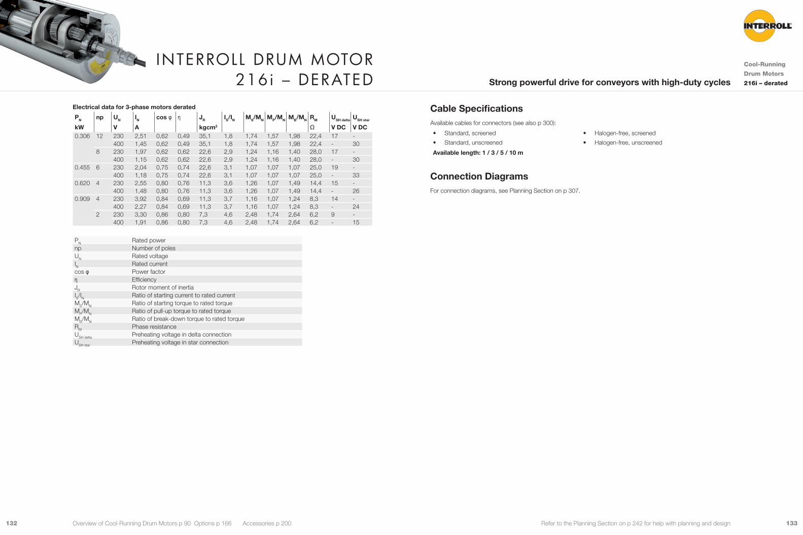
133132 Refer to the Planning Section on p 242 for help with planning and design
Cable SpecificationsAvailable cables for connectors (see also p 300):
• Standard, screened
• Standard, unscreened
• Halogen-free, screened
• Halogen-free, unscreened
Available length: 1 / 3 / 5 / 10 m
Connection DiagramsFor connection diagrams, see Planning Section on p 307.
Electrical data for 3-phase motors derated
PN np UN IN cos φ η JR IS/IN MS/MN MP/MN MB/MN RM USH delta USH star
kW V A kgcm2 Ω V DC V DC0.306 12 230 2,51 0,62 0,49 35,1 1,8 1,74 1,57 1,98 22,4 17 -
400 1,45 0,62 0,49 35,1 1,8 1,74 1,57 1,98 22,4 - 308 230 1,97 0,62 0,62 22,6 2,9 1,24 1,16 1,40 28,0 17 -
400 1,15 0,62 0,62 22,6 2,9 1,24 1,16 1,40 28,0 - 300.455 6 230 2,04 0,75 0,74 22,6 3,1 1,07 1,07 1,07 25,0 19 -
400 1,18 0,75 0,74 22,6 3,1 1,07 1,07 1,07 25,0 - 330.620 4 230 2,55 0,80 0,76 11,3 3,6 1,26 1,07 1,49 14,4 15 -
400 1,48 0,80 0,76 11,3 3,6 1,26 1,07 1,49 14,4 - 260.909 4 230 3,92 0,84 0,69 11,3 3,7 1,16 1,07 1,24 8,3 14 -
400 2,27 0,84 0,69 11,3 3,7 1,16 1,07 1,24 8,3 - 242 230 3,30 0,86 0,80 7,3 4,6 2,48 1,74 2,64 6,2 9 -
400 1,91 0,86 0,80 7,3 4,6 2,48 1,74 2,64 6,2 - 15
PN Rated powernp Number of polesUN Rated voltageIN Rated currentcos φ Power factorη EfficiencyJR Rotor moment of inertiaIS/IN Ratio of starting current to rated currentMS/MN Ratio of starting torque to rated torqueMP/MN Ratio of pull-up torque to rated torqueMB/MN Ratio of break-down torque to rated torqueRM Phase resistanceUSH delta Preheating voltage in delta connectionUSH star Preheating voltage in star connection
Interroll Drum motor 216i – DerateD
Cool-Running
Drum Motors
216i – deratedStrong powerful drive for conveyors with high-duty cycles
Overview of Cool-Running Drum Motors p 90 Options p 166 Accessories p 200
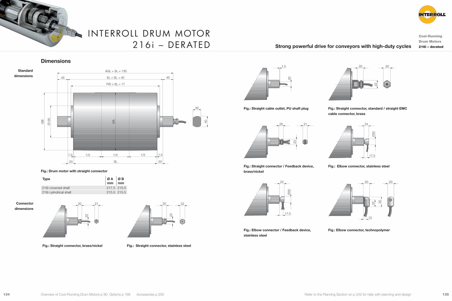
135134 Refer to the Planning Section on p 242 for help with planning and design
1.5
20
22
20 20
Fig.: Straight cable outlet, PU shaft plug Fig.: Straight connector, standard / straight EMC
cable connector, brass
23
20 21
17.5
24
Ø30
Fig.: Straight connector / Feedback device,
brass/nickel
Fig.: Elbow connector, stainless steel
17.5
24
Ø30
22 32
10
20 20
Fig.: Elbow connector / Feedback device,
stainless steel
Fig.: Elbow connector, technopolymer
Dimensions
20 SL
1/31/31/3
Ø13
0
20
EL = SL + 4045 45
30
40ØB
ØA
1.5 1.5
FW = SL + 17
AGL = SL + 130
Fig.: Drum motor with straight connector
Type Ø Amm
Ø Bmm
216i crowned shell 217.5 215.5216i cylindrical shell 215.5 215.5
20
22
21 20
24
22
Fig.: Straight connector, brass/nickel Fig.: Straight connector, stainless steel
Standard
dimensions
Connector
dimensions
Interroll Drum motor 216i – DerateD
Cool-Running
Drum Motors
216i – deratedStrong powerful drive for conveyors with high-duty cycles
Overview of Cool-Running Drum Motors p 90 Options p 166 Accessories p 200

137136 Refer to the Planning Section on p 242 for help with planning and design
20
26.5
50
30° 39
7243
Ø10
5
M20 x 1.5
Fig.: Special cable slot connector Fig.: Terminal box, technopolymer
65
17 22
46
Ø95
14
M20 x 1.5
4347
20° 25
4343
Ø99
14
M20 x 1.5
Fig.: Terminal box, aluminium Fig.: Terminal box, stainless steel
M10
12.5
25
Fig.: Shaft, cross-drilled and threaded
For cross-drilled and threaded hole the shaft flat length is reduced from 45 to 25 mm.
Shafts for fixing
The following options increase the minimum length of the drum motor.
Option Min. SL with option mm
Brake Min. SL + 50Encoder Min. SL + 50Special cable slot connector Min. SL + 50
Standard drum motor lengths and their weights:
Shell length SL in mm 400 450 500 550 600 650 700 750 800 850 900 950 1,000Average weight in kg 46.5 47.8 49.1 50.4 51.7 53.0 54.3 55.6 56.9 58.2 59.5 60.8 62.1
Min. length
with option
Standard length
and weight
Interroll Drum motor 216i – DerateD
Cool-Running
Drum Motors
216i – deratedStrong powerful drive for conveyors with high-duty cycles
Overview of Cool-Running Drum Motors p 90 Options p 166 Accessories p 200
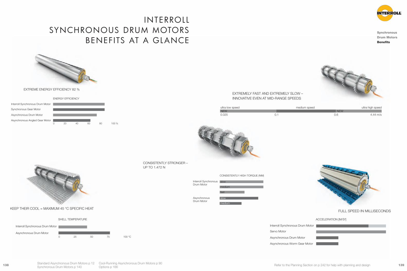
139138 Refer to the Planning Section on p 242 for help with planning and design
Synchronous
Drum Motors
Benefits
Standard Asynchronous Drum Motors p 12 Cool-Running Asynchronous Drum Motors p 90 Synchronous Drum Motors p 140 Options p 166
KEEP THEIR COOL = MAXIMUM 45 °C SPECIFIC HEAT
SHELL TEMPERATURE
Interroll Synchronous Drum Motor
Asynchronous Drum Motor0 25 50 75 100 °C
0 20 40 80 100 %60
EXTREME ENERGY EFFICIENCY 82 %
Interroll Synchronous Drum Motor
Synchronous Gear Motor
Asynchronous Drum Motor
Asynchronous Angled Gear Motor
ENERGY EFFICIENCY
Interroll Synchronous Drum Motor
CONSISTENTLY HIGH TORQUE (NM)
Asynchronous Drum Motor
slow
medium
fast
slow
medium
fast
CONSISTENTLY STRONGER –UP TO 1.472 N
EXTREMELY FAST AND EXTREMELY SLOW –INNOVATIVE EVEN AT MID-RANGE SPEEDS
ultra low speedNEW0.025
medium speed
0.1
ultra high speedNEW
0.6 4.44 m/s
FULL SPEED IN MILLISECONDS
ACCELERATION [M/S²]
Interroll Synchronous Drum Motor
Servo Motor
Asynchronous Drum Motor
Asynchronous Worm Gear Motor
Interroll synChronous Drum motors
benef Its at a GlanCe
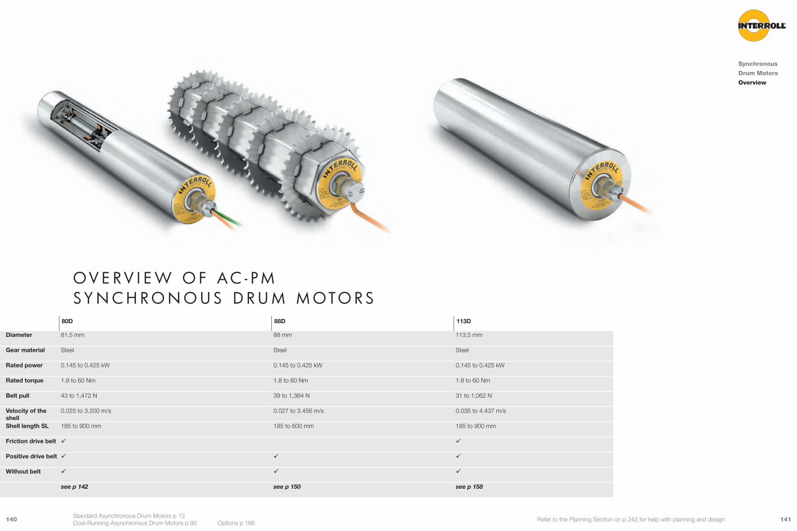
141140 Refer to the Planning Section on p 242 for help with planning and design
o v e r v I e W o f a C - p m sy n C h r o n o u s D r u m m oto r s
80D 88D 113D
Diameter 81.5 mm 88 mm 113.5 mm
Gear material Steel Steel Steel
Rated power 0.145 to 0.425 kW 0.145 to 0.425 kW 0.145 to 0.425 kW
Rated torque 1.8 to 60 Nm 1.8 to 60 Nm 1.8 to 60 Nm
Belt pull 43 to 1,472 N 39 to 1,364 N 31 to 1,062 N
Velocity of the shell
0.025 to 3.200 m/s 0.027 to 3.456 m/s 0.035 to 4.437 m/s
Shell length SL 185 to 900 mm 185 to 600 mm 185 to 900 mm
Friction drive belt 9 9
Positive drive belt 9 9 9
Without belt 9 9 9
see p 142 see p 150 see p 158
Synchronous
Drum Motors
Overview
Standard Asynchronous Drum Motors p 12 Cool-Running Asynchronous Drum Motors p 90 Options p 166
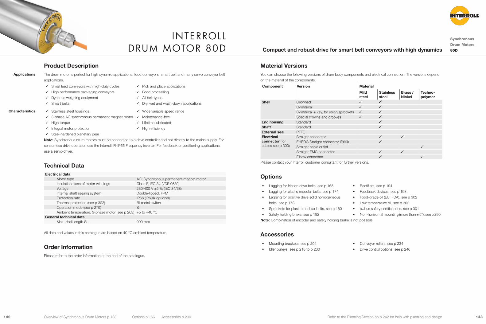
143142 Refer to the Planning Section on p 242 for help with planning and design
Material VersionsYou can choose the following versions of drum body components and electrical connection. The versions depend
on the material of the components.
Component Version Material
Mild steel
Stainless steel
Brass / Nickel
Techno-polymer
Shell Crowned 9 9Cylindrical 9 9Cylindrical + key, for using sprockets 9 9Special crowns and grooves 9 9
End housing Standard 9Shaft Standard 9External seal PTFEElectrical connector (for cables see p 300)
Straight connector 9 9EHEDG Straight connector IP69k 9Straight cable outlet 9Straight EMC connector 9 9Elbow connector 9 9
Please contact your Interroll customer consultant for further versions.
Options• Lagging for friction drive belts, see p 168
• Lagging for plastic modular belts, see p 174
• Lagging for positive drive solid homogeneous
belts, see p 178
• Sprockets for plastic modular belts, see p 180
• Safety holding brake, see p 192
• Rectifiers, see p 194
• Feedback devices, see p 198
• Food-grade oil (EU, FDA), see p 302
• Low temperature oil, see p 302
• cULus safety certifications, see p 301
• Non-horizontal mounting (more than ± 5°), see p 280
Note: Combination of encoder and safety holding brake is not possible.
Accessories• Mounting brackets, see p 204
• Idler pulleys, see p 218 to p 230
• Conveyor rollers, see p 234
• Drive control options, see p 246
Product DescriptionThe drum motor is perfect for high dynamic applications, food conveyors, smart belt and many servo conveyor belt
applications.
9 Small feed conveyors with high-duty cycles
9 High performance packaging conveyors
9 Dynamic weighing equipment
9 Smart belts
9 Pick and place applications
9 Food processing
9 All belt types
9 Dry, wet and wash-down applications
9 Stainless steel housings
9 3-phase AC synchronous permanent magnet motor
9 High torque
9 Integral motor protection
9 Steel-hardened planetary gear
9 Wide variable speed range
9 Maintenance-free
9 Lifetime lubricated
9 High efficiency
Note: Synchronous drum motors must be connected to a drive controller and not directly to the mains supply. For
sensor-less drive operation use the Interroll IFI-IP55 Frequency inverter. For feedback or positioning applications
use a servo-driver.
Technical DataElectrical data
Motor type AC Synchronous permanent magnet motorInsulation class of motor windings Class F, IEC 34 (VDE 0530)Voltage 230/400 V ±5 % (IEC 34/38)Internal shaft sealing system Double-lipped, FPMProtection rate IP66 (IP69K optional)Thermal protection (see p 302) Bi-metal switchOperation mode (see p 279) S1Ambient temperature, 3-phase motor (see p 263) +5 to +40 °C
General technical data Max. shell length SL 900 mm
All data and values in this catalogue are based on 40 °C ambient temperature.
Order InformationPlease refer to the order information at the end of the catalogue.
Applications
Characteristics
Interroll Drum motor 80D
Synchronous
Drum Motors
80DCompact and robust drive for smart belt conveyors with high dynamics
Overview of Synchronous Drum Motors p 138 Options p 166 Accessories p 200

145144 Refer to the Planning Section on p 242 for help with planning and design
PN Rated powernp Number of polesgs Gear stagesi Gear ratiov Rated velocity of the shellnA Rated revolutions of the shellMA Rated torque of drum motorFN Rated belt pull of drum motorTE Max. belt tensionSLmin Min. shell lengthApp. 9: Suitable for all applications. This version will ensure lowest cost and fast delivery
û: Not suitable for all applications. Please contact your Interroll customer consultant
Product RangeThe following tables give an overview of the possible motor versions. When ordering, please specify the version in
accordance with the configurator at the end of the catalogue.
Mechanical data for 3-phase motors
PN np gs i v nA MA FN TE SLmin App.
kW m/s min-1 Nm N N mm 0.145 8 3 512 0.025 5.9 28.0 687 3,250 215 û
320 0.040 9.4 60.0 1,472 3,250 215 û256 0.050 12 60.0 1,472 3,250 215 û200 0.064 15 60.0 1,472 3,250 215 û160 0.080 19 59.9 1,469 3,250 215 9120 0.107 25 44.9 1,102 3,250 215 9100 0.128 30 41.1 1,009 3,250 215 980 0.160 38 32.9 807 3,250 215 960 0.213 50 24.7 605 3,250 215 9
2 40 0.320 75 17.0 417 3,250 200 932 0.400 94 13.6 334 3,250 200 925 0.512 120 10.6 261 3,250 200 920 0.640 150 8.5 209 3,250 200 916 0.800 188 6.8 167 3,250 200 912 1.067 250 5.1 125 3,250 200 9
1 8 1.600 375 3.5 86 3,250 185 95 2.560 600 2.2 54 3,250 185 û4 3.200 750 1.8 43 3,250 185 û
0.298 8 3 60 0.213 50 50.7 1,244 3,250 265 92 40 0.320 75 34.9 857 3,250 250 9
32 0.400 94 27.9 686 3,250 250 925 0.512 120 21.8 536 3,250 250 920 0.640 150 17.5 429 3,250 250 916 0.800 188 14.0 343 3,250 250 912 1.067 250 10.5 257 3,250 250 9
1 8 1.600 375 7.2 177 3,250 235 95 2.560 600 4.5 111 3,250 235 û4 3.200 750 3.6 88 3,250 235 û
0.425 8 2 40 0.320 75 49.8 1,222 3,250 265 932 0.400 94 39.8 977 3,250 265 925 0.512 120 31.1 764 3,250 265 920 0.640 150 24.9 611 3,250 265 916 0.800 188 19.9 489 3,250 265 912 1.067 250 14.9 367 3,250 265 9
1 8 1.600 375 10.3 252 3,250 250 95 2.560 600 6.4 158 3,250 250 û4 3.200 750 5.1 126 3,250 250 û
Motor versions
Interroll Drum motor 80D
Synchronous
Drum Motors
80DCompact and robust drive for smart belt conveyors with high dynamics
Overview of Synchronous Drum Motors p 138 Options p 166 Accessories p 200
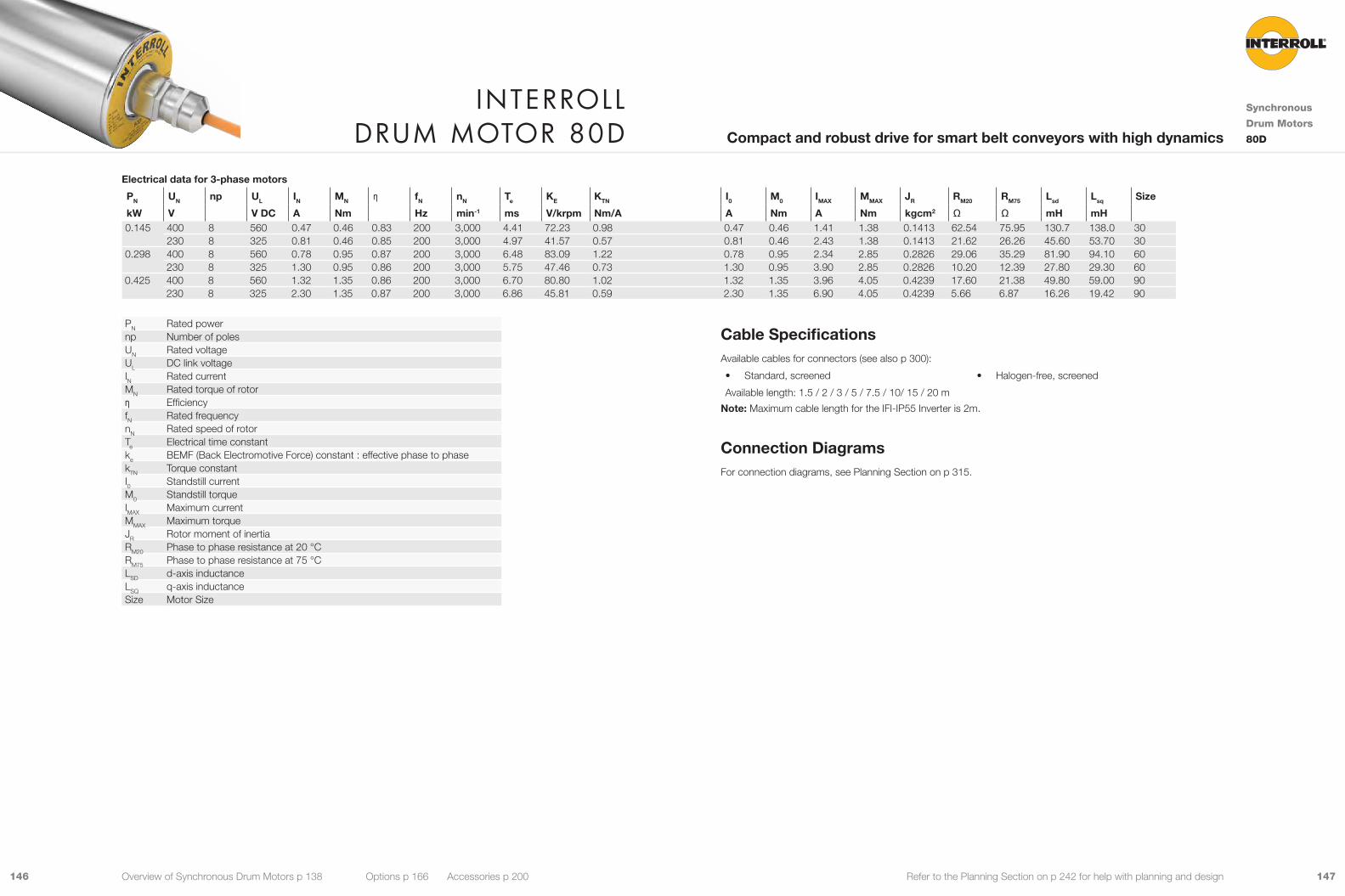
147146 Refer to the Planning Section on p 242 for help with planning and design
Cable SpecificationsAvailable cables for connectors (see also p 300):
• Standard, screened • Halogen-free, screened
Available length: 1.5 / 2 / 3 / 5 / 7.5 / 10/ 15 / 20 m
Note: Maximum cable length for the IFI-IP55 Inverter is 2m.
Connection DiagramsFor connection diagrams, see Planning Section on p 315.
Electrical data for 3-phase motors
PN UN np UL IN MN η fN nN Te KE KTN I0 M0 IMAX MMAX JR RM20 RM75 Lsd Lsq Size
kW V V DC A Nm Hz min-1 ms V/krpm Nm/A A Nm A Nm kgcm2 Ω Ω mH mH 0.145 400 8 560 0.47 0.46 0.83 200 3,000 4.41 72.23 0.98 0.47 0.46 1.41 1.38 0.1413 62.54 75.95 130.7 138.0 30
230 8 325 0.81 0.46 0.85 200 3,000 4.97 41.57 0.57 0.81 0.46 2.43 1.38 0.1413 21.62 26.26 45.60 53.70 300.298 400 8 560 0.78 0.95 0.87 200 3,000 6.48 83.09 1.22 0.78 0.95 2.34 2.85 0.2826 29.06 35.29 81.90 94.10 60
230 8 325 1.30 0.95 0.86 200 3,000 5.75 47.46 0.73 1.30 0.95 3.90 2.85 0.2826 10.20 12.39 27.80 29.30 600.425 400 8 560 1.32 1.35 0.86 200 3,000 6.70 80.80 1.02 1.32 1.35 3.96 4.05 0.4239 17.60 21.38 49.80 59.00 90
230 8 325 2.30 1.35 0.87 200 3,000 6.86 45.81 0.59 2.30 1.35 6.90 4.05 0.4239 5.66 6.87 16.26 19.42 90
PN Rated powernp Number of polesUN Rated voltageUL DC link voltageIN Rated currentMN Rated torque of rotorη EfficiencyfN Rated frequencynN Rated speed of rotorTe Electrical time constantke BEMF (Back Electromotive Force) constant : effective phase to phasekTN Torque constantI0 Standstill currentM0 Standstill torqueIMAX Maximum currentMMAX Maximum torqueJR Rotor moment of inertiaRM20 Phase to phase resistance at 20 °CRM75 Phase to phase resistance at 75 °CLSD d-axis inductanceLSQ q-axis inductanceSize Motor Size
Interroll Drum motor 80D
Synchronous
Drum Motors
80DCompact and robust drive for smart belt conveyors with high dynamics
Overview of Synchronous Drum Motors p 138 Options p 166 Accessories p 200
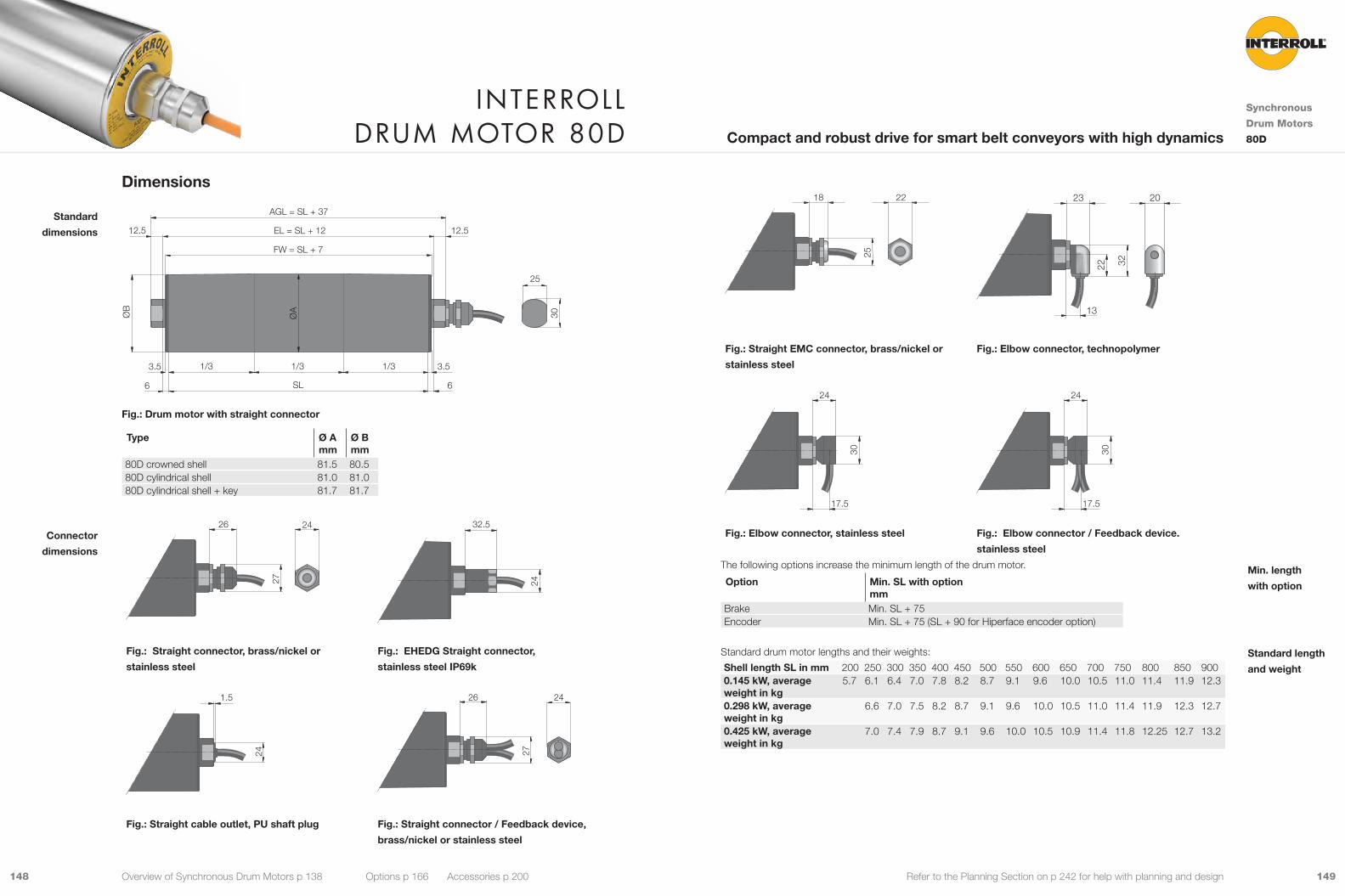
149148 Refer to the Planning Section on p 242 for help with planning and design25
18 22
22 32
13
23 20
Fig.: Straight EMC connector, brass/nickel or
stainless steel
Fig.: Elbow connector, technopolymer
30
17.5
24
30
17.5
24
Fig.: Elbow connector, stainless steel Fig.: Elbow connector / Feedback device.
stainless steel
The following options increase the minimum length of the drum motor.
Option Min. SL with option mm
Brake Min. SL + 75Encoder Min. SL + 75 (SL + 90 for Hiperface encoder option)
Standard drum motor lengths and their weights:
Shell length SL in mm 200 250 300 350 400 450 500 550 600 650 700 750 800 850 9000.145 kW, average weight in kg
5.7 6.1 6.4 7.0 7.8 8.2 8.7 9.1 9.6 10.0 10.5 11.0 11.4 11.9 12.3
0.298 kW, average weight in kg
6.6 7.0 7.5 8.2 8.7 9.1 9.6 10.0 10.5 11.0 11.4 11.9 12.3 12.7
0.425 kW, average weight in kg
7.0 7.4 7.9 8.7 9.1 9.6 10.0 10.5 10.9 11.4 11.8 12.25 12.7 13.2
Min. length
with option
Standard length
and weight
Dimensions
6
3.5 3.5
12.512.5
6
1/3 1/3 1/3
25
EL = SL + 12
FW = SL + 7
AGL = SL + 37
SL
ØA
ØB
30
Fig.: Drum motor with straight connector
Type Ø Amm
Ø Bmm
80D crowned shell 81.5 80.580D cylindrical shell 81.0 81.080D cylindrical shell + key 81.7 81.7
27
26 2424
32.5
Fig.: Straight connector, brass/nickel or
stainless steel
Fig.: EHEDG Straight connector,
stainless steel IP69k
24
1.5
27
26 24
Fig.: Straight cable outlet, PU shaft plug Fig.: Straight connector / Feedback device,
brass/nickel or stainless steel
Standard
dimensions
Connector
dimensions
Interroll Drum motor 80D
Synchronous
Drum Motors
80DCompact and robust drive for smart belt conveyors with high dynamics
Overview of Synchronous Drum Motors p 138 Options p 166 Accessories p 200
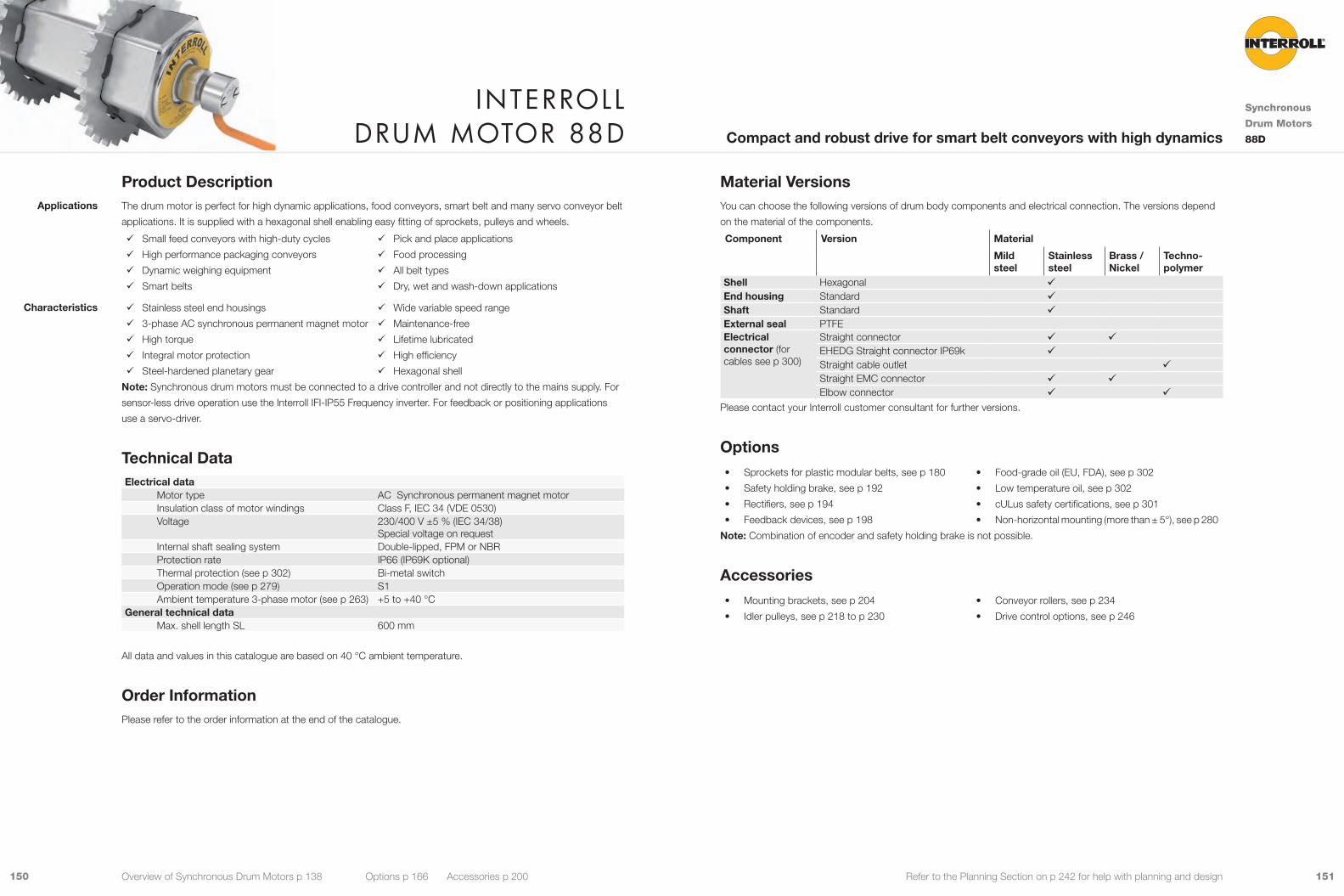
151150 Refer to the Planning Section on p 242 for help with planning and design
Material VersionsYou can choose the following versions of drum body components and electrical connection. The versions depend
on the material of the components.
Component Version Material
Mild steel
Stainless steel
Brass / Nickel
Techno-polymer
Shell Hexagonal 9End housing Standard 9Shaft Standard 9External seal PTFEElectrical connector (for cables see p 300)
Straight connector 9 9EHEDG Straight connector IP69k 9Straight cable outlet 9Straight EMC connector 9 9Elbow connector 9 9
Please contact your Interroll customer consultant for further versions.
Options• Sprockets for plastic modular belts, see p 180
• Safety holding brake, see p 192
• Rectifiers, see p 194
• Feedback devices, see p 198
• Food-grade oil (EU, FDA), see p 302
• Low temperature oil, see p 302
• cULus safety certifications, see p 301
• Non-horizontal mounting (more than ± 5°), see p 280
Note: Combination of encoder and safety holding brake is not possible.
Accessories• Mounting brackets, see p 204
• Idler pulleys, see p 218 to p 230
• Conveyor rollers, see p 234
• Drive control options, see p 246
Product DescriptionThe drum motor is perfect for high dynamic applications, food conveyors, smart belt and many servo conveyor belt
applications. It is supplied with a hexagonal shell enabling easy fitting of sprockets, pulleys and wheels.
9 Small feed conveyors with high-duty cycles
9 High performance packaging conveyors
9 Dynamic weighing equipment
9 Smart belts
9 Pick and place applications
9 Food processing
9 All belt types
9 Dry, wet and wash-down applications
9 Stainless steel end housings
9 3-phase AC synchronous permanent magnet motor
9 High torque
9 Integral motor protection
9 Steel-hardened planetary gear
9 Wide variable speed range
9 Maintenance-free
9 Lifetime lubricated
9 High efficiency
9 Hexagonal shell
Note: Synchronous drum motors must be connected to a drive controller and not directly to the mains supply. For
sensor-less drive operation use the Interroll IFI-IP55 Frequency inverter. For feedback or positioning applications
use a servo-driver.
Technical DataElectrical data
Motor type AC Synchronous permanent magnet motorInsulation class of motor windings Class F, IEC 34 (VDE 0530)Voltage 230/400 V ±5 % (IEC 34/38)
Special voltage on requestInternal shaft sealing system Double-lipped, FPM or NBRProtection rate IP66 (IP69K optional)Thermal protection (see p 302) Bi-metal switchOperation mode (see p 279) S1Ambient temperature 3-phase motor (see p 263) +5 to +40 °C
General technical data Max. shell length SL 600 mm
All data and values in this catalogue are based on 40 °C ambient temperature.
Order InformationPlease refer to the order information at the end of the catalogue.
Applications
Characteristics
Interroll Drum motor 88D
Synchronous
Drum Motors
88DCompact and robust drive for smart belt conveyors with high dynamics
Overview of Synchronous Drum Motors p 138 Options p 166 Accessories p 200
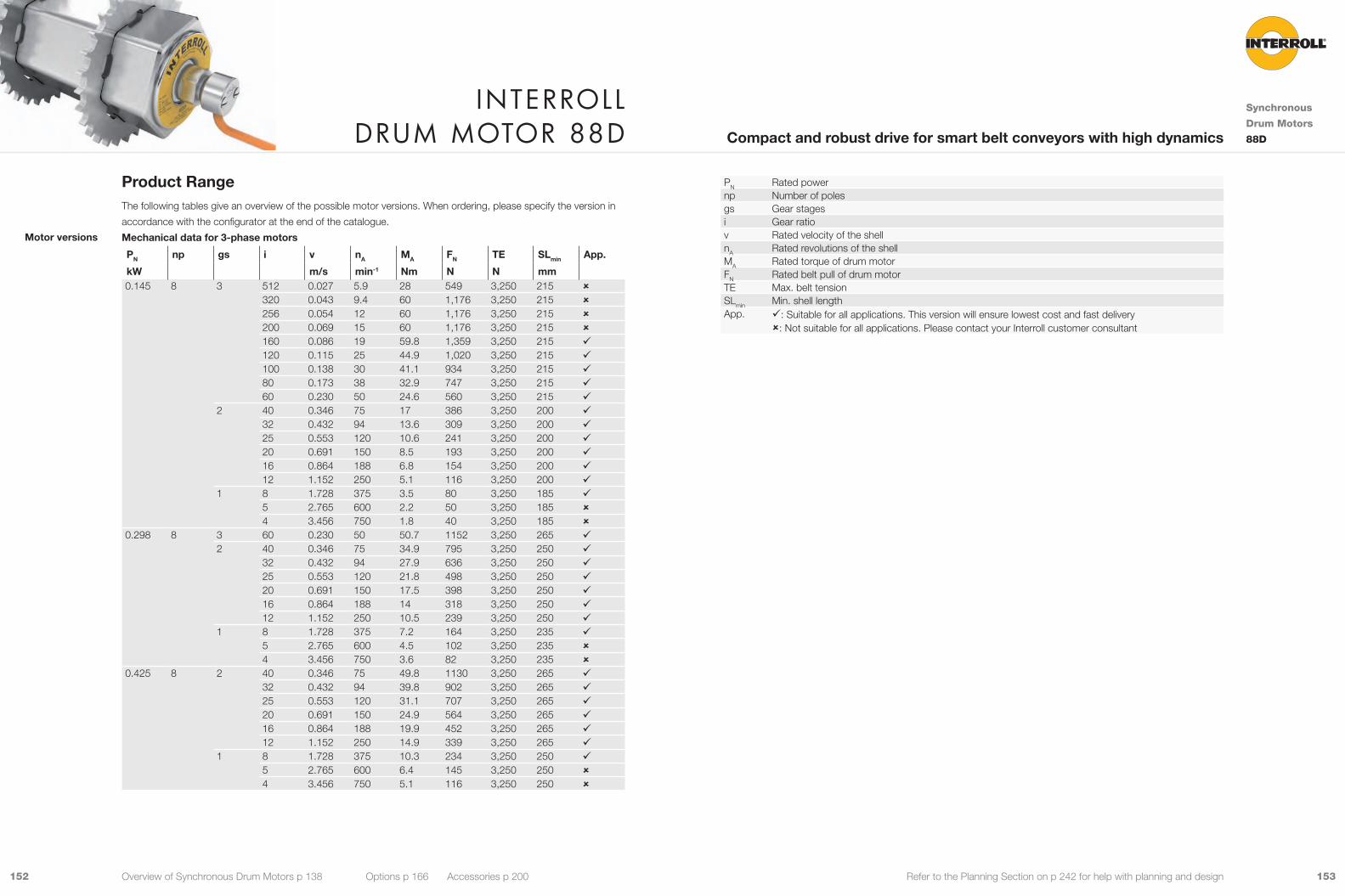
153152 Refer to the Planning Section on p 242 for help with planning and design
PN Rated powernp Number of polesgs Gear stagesi Gear ratiov Rated velocity of the shellnA Rated revolutions of the shellMA Rated torque of drum motorFN Rated belt pull of drum motorTE Max. belt tensionSLmin Min. shell lengthApp. 9: Suitable for all applications. This version will ensure lowest cost and fast delivery
û: Not suitable for all applications. Please contact your Interroll customer consultant
Product RangeThe following tables give an overview of the possible motor versions. When ordering, please specify the version in
accordance with the configurator at the end of the catalogue.
Mechanical data for 3-phase motors
PN np gs i v nA MA FN TE SLmin App.
kW m/s min-1 Nm N N mm 0.145 8 3 512 0.027 5.9 28 549 3,250 215 û
320 0.043 9.4 60 1,176 3,250 215 û256 0.054 12 60 1,176 3,250 215 û200 0.069 15 60 1,176 3,250 215 û160 0.086 19 59.8 1,359 3,250 215 9120 0.115 25 44.9 1,020 3,250 215 9100 0.138 30 41.1 934 3,250 215 980 0.173 38 32.9 747 3,250 215 960 0.230 50 24.6 560 3,250 215 9
2 40 0.346 75 17 386 3,250 200 932 0.432 94 13.6 309 3,250 200 925 0.553 120 10.6 241 3,250 200 920 0.691 150 8.5 193 3,250 200 916 0.864 188 6.8 154 3,250 200 912 1.152 250 5.1 116 3,250 200 9
1 8 1.728 375 3.5 80 3,250 185 95 2.765 600 2.2 50 3,250 185 û4 3.456 750 1.8 40 3,250 185 û
0.298 8 3 60 0.230 50 50.7 1152 3,250 265 92 40 0.346 75 34.9 795 3,250 250 9
32 0.432 94 27.9 636 3,250 250 925 0.553 120 21.8 498 3,250 250 920 0.691 150 17.5 398 3,250 250 916 0.864 188 14 318 3,250 250 912 1.152 250 10.5 239 3,250 250 9
1 8 1.728 375 7.2 164 3,250 235 95 2.765 600 4.5 102 3,250 235 û4 3.456 750 3.6 82 3,250 235 û
0.425 8 2 40 0.346 75 49.8 1130 3,250 265 932 0.432 94 39.8 902 3,250 265 925 0.553 120 31.1 707 3,250 265 920 0.691 150 24.9 564 3,250 265 916 0.864 188 19.9 452 3,250 265 912 1.152 250 14.9 339 3,250 265 9
1 8 1.728 375 10.3 234 3,250 250 95 2.765 600 6.4 145 3,250 250 û4 3.456 750 5.1 116 3,250 250 û
Motor versions
Interroll Drum motor 88D
Synchronous
Drum Motors
88DCompact and robust drive for smart belt conveyors with high dynamics
Overview of Synchronous Drum Motors p 138 Options p 166 Accessories p 200

155154 Refer to the Planning Section on p 242 for help with planning and design
Cable SpecificationsAvailable cables for connectors (see also p 300):
• Standard, screened • Halogen-free, screened
Available length: 1.5 / 2 / 3 / 5 / 7.5 / 10 / 15 / 20 m
Note: Maximum cable length for the IFI-IP55 Inverter is 2m.
Connection DiagramsFor connection diagrams, see Planning Section on p 315.
Electrical data for 3-phase motors
PN UN np UL IN MN η fN nN Te KE KTN I0 M0 IMAX MMAX JR RM20 RM75 Lsd Lsq Size
kW V V DC A Nm Hz min-1 ms V/krpm Nm/A A Nm A Nm kgcm2 Ω Ω mH mH 0.145 400 8 560 0.47 0.46 0.83 200 3,000 4.41 72.23 0.98 0.47 0.46 1.41 1.38 0.1413 62.54 75.95 130.7 138.0 30
230 8 325 0.81 0.46 0.85 200 3,000 4.97 41.57 0.57 0.81 0.46 2.43 1.38 0.1413 21.62 26.26 45.60 53.70 300.298 400 8 560 0.78 0.95 0.87 200 3,000 6.48 83.09 1.22 0.78 0.95 2.34 2.85 0.2826 29.06 35.29 81.90 94.10 60
230 8 325 1.30 0.95 0.86 200 3,000 5.75 47.46 0.73 1.30 0.95 3.90 2.85 0.2826 10.20 12.39 27.80 29.30 600.425 400 8 560 1.32 1.35 0.86 200 3,000 6.70 80.80 1.02 1.32 1.35 3.96 4.05 0.4239 17.60 21.38 49.80 59.00 90
230 8 325 2.30 1.35 0.87 200 3,000 6.86 45.81 0.59 2.30 1.35 6.90 4.05 0.4239 5.66 6.87 16.26 19.42 90
PN Rated powernp Number of polesUN Rated voltageUL DC link voltageIN Rated currentMN Rated torque of rotorη EfficiencyfN Rated frequencynN Rated speed of rotorTe Electrical time constantke BEMF (Back Electromotive Force) constant : effective phase to phasekTN Torque constantI0 Standstill currentM0 Standstill torqueIMAX Maximum currentMMAX Maximum torqueJR Rotor moment of inertiaRM20 Phase to phase resistance at 20 °CRM75 Phase to phase resistance at 75 °CLSD d-axis inductanceLSQ q-axis inductanceSize Motor Size
Interroll Drum motor 88D
Synchronous
Drum Motors
88DCompact and robust drive for smart belt conveyors with high dynamics
Overview of Synchronous Drum Motors p 138 Options p 166 Accessories p 200
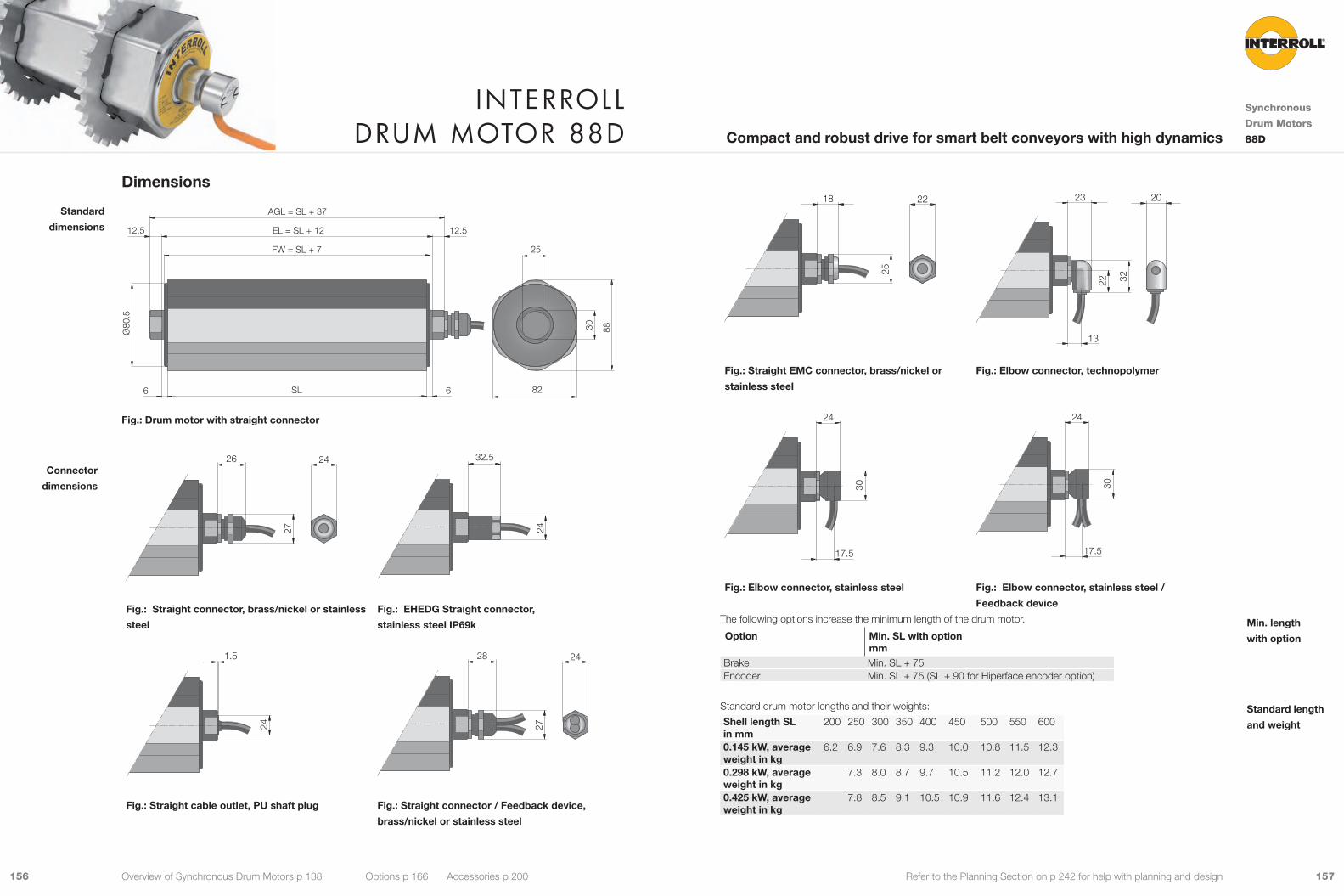
157156 Refer to the Planning Section on p 242 for help with planning and design25
18 22
22 32
13
23 20
Fig.: Straight EMC connector, brass/nickel or
stainless steel
Fig.: Elbow connector, technopolymer
30
17.5
24
30
17.5
24
Fig.: Elbow connector, stainless steel Fig.: Elbow connector, stainless steel /
Feedback device
The following options increase the minimum length of the drum motor.
Option Min. SL with option mm
Brake Min. SL + 75Encoder Min. SL + 75 (SL + 90 for Hiperface encoder option)
Standard drum motor lengths and their weights:
Shell length SL in mm
200 250 300 350 400 450 500 550 600
0.145 kW, average weight in kg
6.2 6.9 7.6 8.3 9.3 10.0 10.8 11.5 12.3
0.298 kW, average weight in kg
7.3 8.0 8.7 9.7 10.5 11.2 12.0 12.7
0.425 kW, average weight in kg
7.8 8.5 9.1 10.5 10.9 11.6 12.4 13.1
Min. length
with option
Standard length
and weight
Dimensions
6 82
12.512.5
6
25
EL = SL + 12
FW = SL + 7
AGL = SL + 37
SL
Ø80
.5
30 88
Fig.: Drum motor with straight connector
27
26 24
24
32.5
Fig.: Straight connector, brass/nickel or stainless
steel
Fig.: EHEDG Straight connector,
stainless steel IP69k
24
1.5
27
28 24
Fig.: Straight cable outlet, PU shaft plug Fig.: Straight connector / Feedback device,
brass/nickel or stainless steel
Standard
dimensions
Connector
dimensions
Interroll Drum motor 88D
Synchronous
Drum Motors
88DCompact and robust drive for smart belt conveyors with high dynamics
Overview of Synchronous Drum Motors p 138 Options p 166 Accessories p 200
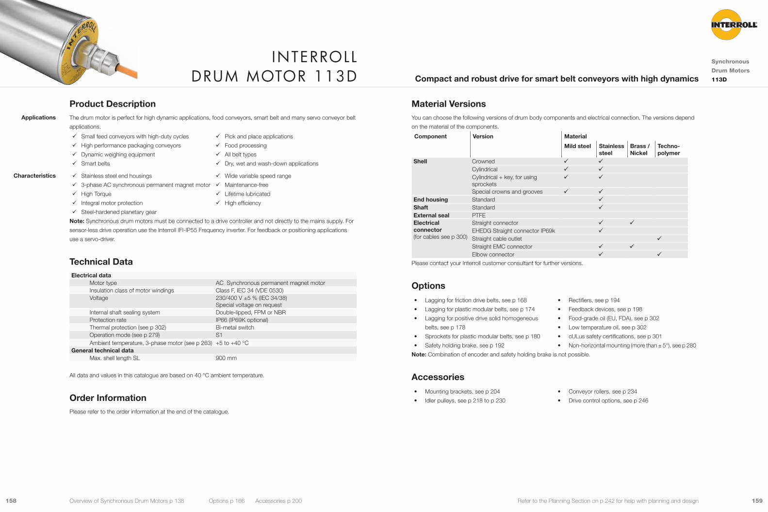
159158 Refer to the Planning Section on p 242 for help with planning and design
Material VersionsYou can choose the following versions of drum body components and electrical connection. The versions depend
on the material of the components.
Component Version Material
Mild steel Stainless steel
Brass / Nickel
Techno- polymer
Shell Crowned 9 9Cylindrical 9 9Cylindrical + key, for using sprockets
9 9
Special crowns and grooves 9 9End housing Standard 9Shaft Standard 9External seal PTFEElectrical connector (for cables see p 300)
Straight connector 9 9EHEDG Straight connector IP69k 9Straight cable outlet 9Straight EMC connector 9 9Elbow connector 9 9
Please contact your Interroll customer consultant for further versions.
Options• Lagging for friction drive belts, see p 168
• Lagging for plastic modular belts, see p 174
• Lagging for positive drive solid homogeneous
belts, see p 178
• Sprockets for plastic modular belts, see p 180
• Safety holding brake, see p 192
• Rectifiers, see p 194
• Feedback devices, see p 198
• Food-grade oil (EU, FDA), see p 302
• Low temperature oil, see p 302
• cULus safety certifications, see p 301
• Non-horizontal mounting (more than ± 5°), see p 280
Note: Combination of encoder and safety holding brake is not possible.
Accessories• Mounting brackets, see p 204
• Idler pulleys, see p 218 to p 230
• Conveyor rollers, see p 234
• Drive control options, see p 246
Product DescriptionThe drum motor is perfect for high dynamic applications, food conveyors, smart belt and many servo conveyor belt
applications.
9 Small feed conveyors with high-duty cycles
9 High performance packaging conveyors
9 Dynamic weighing equipment
9 Smart belts
9 Pick and place applications
9 Food processing
9 All belt types
9 Dry, wet and wash-down applications
9 Stainless steel end housings
9 3-phase AC synchronous permanent magnet motor
9 High Torque
9 Integral motor protection
9 Steel-hardened planetary gear
9 Wide variable speed range
9 Maintenance-free
9 Lifetime lubricated
9 High efficiency
Note: Synchronous drum motors must be connected to a drive controller and not directly to the mains supply. For
sensor-less drive operation use the Interroll IFI-IP55 Frequency inverter. For feedback or positioning applications
use a servo-driver.
Technical DataElectrical data
Motor type AC Synchronous permanent magnet motorInsulation class of motor windings Class F, IEC 34 (VDE 0530)Voltage 230/400 V ±5 % (IEC 34/38)
Special voltage on requestInternal shaft sealing system Double-lipped, FPM or NBRProtection rate IP66 (IP69K optional)Thermal protection (see p 302) Bi-metal switchOperation mode (see p 279) S1Ambient temperature, 3-phase motor (see p 263) +5 to +40 °C
General technical data Max. shell length SL 900 mm
All data and values in this catalogue are based on 40 °C ambient temperature.
Order InformationPlease refer to the order information at the end of the catalogue.
Applications
Characteristics
Interroll Drum motor 113D
Synchronous
Drum Motors
113DCompact and robust drive for smart belt conveyors with high dynamics
Overview of Synchronous Drum Motors p 138 Options p 166 Accessories p 200
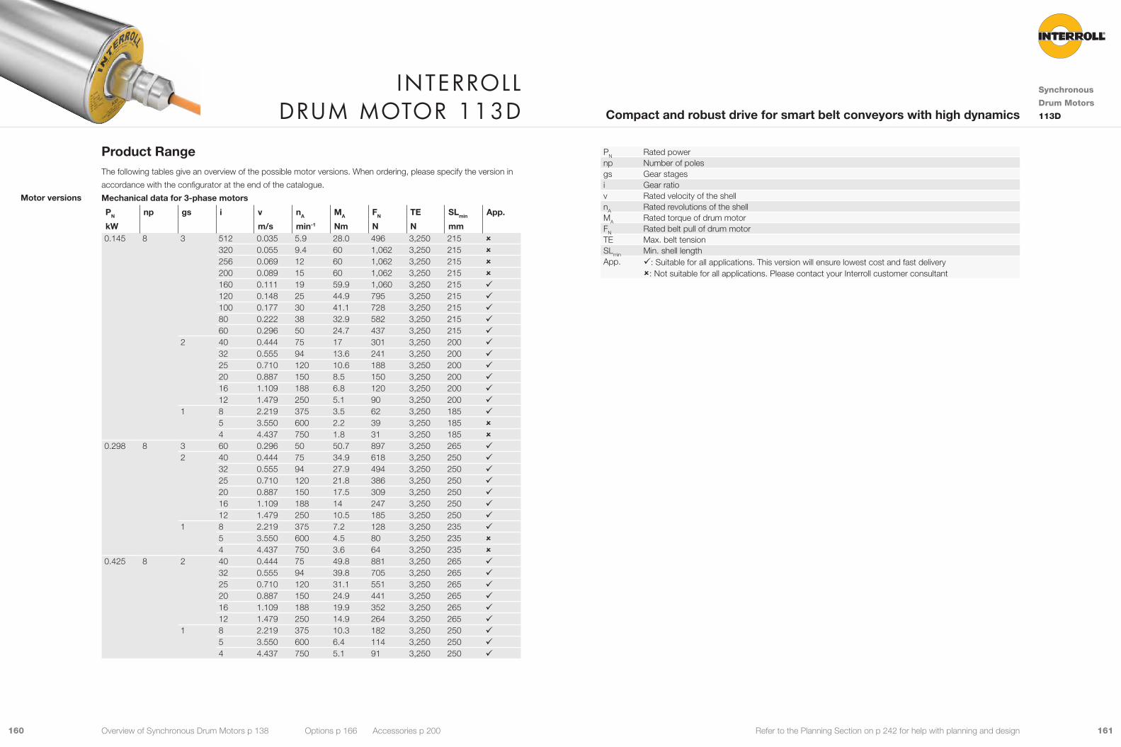
161160 Refer to the Planning Section on p 242 for help with planning and design
PN Rated powernp Number of polesgs Gear stagesi Gear ratiov Rated velocity of the shellnA Rated revolutions of the shellMA Rated torque of drum motorFN Rated belt pull of drum motorTE Max. belt tensionSLmin Min. shell lengthApp. 9: Suitable for all applications. This version will ensure lowest cost and fast delivery
û: Not suitable for all applications. Please contact your Interroll customer consultant
Product RangeThe following tables give an overview of the possible motor versions. When ordering, please specify the version in
accordance with the configurator at the end of the catalogue.
Mechanical data for 3-phase motors
PN np gs i v nA MA FN TE SLmin App.
kW m/s min-1 Nm N N mm 0.145 8 3 512 0.035 5.9 28.0 496 3,250 215 û
320 0.055 9.4 60 1,062 3,250 215 û256 0.069 12 60 1,062 3,250 215 û200 0.089 15 60 1,062 3,250 215 û160 0.111 19 59.9 1,060 3,250 215 9120 0.148 25 44.9 795 3,250 215 9100 0.177 30 41.1 728 3,250 215 980 0.222 38 32.9 582 3,250 215 960 0.296 50 24.7 437 3,250 215 9
2 40 0.444 75 17 301 3,250 200 932 0.555 94 13.6 241 3,250 200 925 0.710 120 10.6 188 3,250 200 920 0.887 150 8.5 150 3,250 200 916 1.109 188 6.8 120 3,250 200 912 1.479 250 5.1 90 3,250 200 9
1 8 2.219 375 3.5 62 3,250 185 95 3.550 600 2.2 39 3,250 185 û4 4.437 750 1.8 31 3,250 185 û
0.298 8 3 60 0.296 50 50.7 897 3,250 265 92 40 0.444 75 34.9 618 3,250 250 9
32 0.555 94 27.9 494 3,250 250 925 0.710 120 21.8 386 3,250 250 920 0.887 150 17.5 309 3,250 250 916 1.109 188 14 247 3,250 250 912 1.479 250 10.5 185 3,250 250 9
1 8 2.219 375 7.2 128 3,250 235 95 3.550 600 4.5 80 3,250 235 û4 4.437 750 3.6 64 3,250 235 û
0.425 8 2 40 0.444 75 49.8 881 3,250 265 932 0.555 94 39.8 705 3,250 265 925 0.710 120 31.1 551 3,250 265 920 0.887 150 24.9 441 3,250 265 916 1.109 188 19.9 352 3,250 265 912 1.479 250 14.9 264 3,250 265 9
1 8 2.219 375 10.3 182 3,250 250 95 3.550 600 6.4 114 3,250 250 94 4.437 750 5.1 91 3,250 250 9
Motor versions
Interroll Drum motor 113D
Synchronous
Drum Motors
113DCompact and robust drive for smart belt conveyors with high dynamics
Overview of Synchronous Drum Motors p 138 Options p 166 Accessories p 200

163162 Refer to the Planning Section on p 242 for help with planning and design
Cable SpecificationsAvailable cables for connectors (see also p 300):
• Standard, screened • Halogen-free, screened
Available length: 1.5 / 2 / 3 / 5 / 7.5 / 10 / 15 / 20 m
Note: Maximum cable length for the IFI-IP55 Inverter is 2m.
Connection DiagramsFor connection diagrams, see Planning Section on p 315.
Electrical data for 3-phase motors
PN UN np UL IN MN η fN nN Te KE KTN I0 M0 IMAX MMAX JR RM20 RM75 Lsd Lsq Size
kW V V DC A Nm Hz min-1 ms V/krpm Nm/A A Nm A Nm kgcm2 Ω Ω mH mH 0.145 400 8 560 0.47 0.46 0.83 200 3,000 4.41 72.23 0.98 0.47 0.46 1.41 1.38 0.1413 62.54 75.95 130.7 138.0 30
230 8 325 0.81 0.46 0.85 200 3,000 4.97 41.57 0.57 0.81 0.46 2.43 1.38 0.1413 21.62 26.26 45.60 53.70 300.298 400 8 560 0.78 0.95 0.87 200 3,000 6.48 83.09 1.22 0.78 0.95 2.34 2.85 0.2826 29.06 35.29 81.90 94.10 60
230 8 325 1.30 0.95 0.86 200 3,000 5.75 47.46 0.73 1.30 0.95 3.90 2.85 0.2826 10.20 12.39 27.80 29.30 600.425 400 8 560 1.32 1.35 0.86 200 3,000 6.70 80.80 1.02 1.32 1.35 3.96 4.05 0.4239 17.60 21.38 49.80 59.00 90
230 8 325 2.30 1.35 0.87 200 3,000 6.86 45.81 0.59 2.30 1.35 6.90 4.05 0.4239 5.66 6.87 16.26 19.42 90
PN Rated powernp Number of polesUN Rated voltageUL DC link voltageIN Rated currentMN Rated torque of rotorη EfficiencyfN Rated frequencynN Rated speed of rotorTe Electrical time constantke BEMF (Back Electromotive Force) constant : effective phase to phasekTN Torque constantI0 Standstill currentM0 Standstill torqueIMAX Maximum currentMMAX Maximum torqueJR Rotor moment of inertiaRM20 Phase to phase resistance at 20 °CRM75 Phase to phase resistance at 75 °CLSD d-axis inductanceLSQ q-axis inductanceSize Motor Size
Interroll Drum motor 113D
Synchronous
Drum Motors
113DCompact and robust drive for smart belt conveyors with high dynamics
Overview of Synchronous Drum Motors p 138 Options p 166 Accessories p 200

165164 Refer to the Planning Section on p 242 for help with planning and design25
18 22
22 32
13
23 20
Fig.: Straight EMC connector, brass/nickel or
stainless steel
Fig.: Elbow connector, technopolymer
30
17.5
24
30
17.5
24
Fig.: Elbow connector, stainless steel Fig.: Elbow connector, stainless steel /
Feedback device
The following options increase the minimum length of the drum motor.
Option Min. SL with option mm
Brake Min. SL + 75Encoder Min. SL + 75 (SL + 90 for Hiperface encoder option)
Standard drum motor lengths and their weights:
Shell length SL in mm
200 250 300 350 400 450 500 550 600 650 700 750 800 850 900
0.145 kW, average weight in kg
9.0 9.7 10.4 11.1 12.0 12.7 13.4 14.1 14.8 15.6 16.3 17.0 17.7 18.4 19.2
0.298 kW, average weight in kg
10.2 10.6 11.6 12.4 13.1 13.8 14.6 15.3 16.0 16.7 17.4 18.2 18.9 19.6
0.425 kW, average weight in kg
10.6 11.3 12.0 12.8 13.5 14.3 15.0 15.7 16.4 17.1 17.9 18.6 19.3 20.0
Min. length
with option
Standard length
and weight
Dimensions
6
3,5 3,5
12,512,5
6
1/3 1/3 1/3
25
EL = SL + 12
FW = SL + 7
AGL = SL + 37
SL
ØA
ØB 30
Type Ø Amm
Ø Bmm
113D crowned shell 113.5 112.0113D cylindrical shell 112.0 112.0113D cylindrical shell + key 113.0 113.0
27
26 2424
32.5
Fig.: Straight connector, brass/nickel or
stainless steel
Fig.: EHEDG Straight connector, stainless steel
IP69k
24
1.5
27
26 24
Fig.: Straight cable outlet, PU shaft plug Fig.: Straight connector / Feedback device,
brass/nickel or stainless steel
Standard
dimensions
Connector
dimensions
Interroll Drum motor 113D
Synchronous
Drum Motors
113DCompact and robust drive for smart belt conveyors with high dynamics
Overview of Synchronous Drum Motors p 138 Options p 166 Accessories p 200
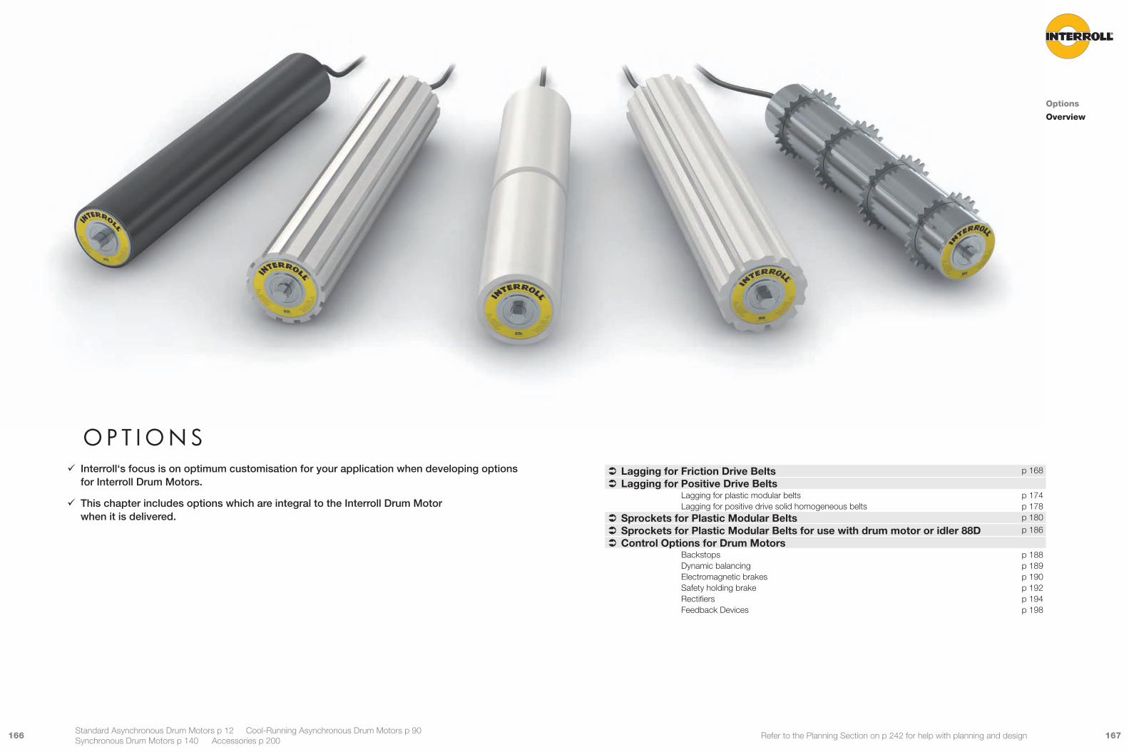
167166 Refer to the Planning Section on p 242 for help with planning and design
o p t I o n s 9 Interroll‘s focus is on optimum customisation for your application when developing options for Interroll Drum Motors.
9 This chapter includes options which are integral to the Interroll Drum Motor when it is delivered.
Options
Overview
Standard Asynchronous Drum Motors p 12 Cool-Running Asynchronous Drum Motors p 90 Synchronous Drum Motors p 140 Accessories p 200
 Lagging for Friction Drive Belts p 168
 Lagging for Positive Drive BeltsLagging for plastic modular belts p 174Lagging for positive drive solid homogeneous belts p 178
 Sprockets for Plastic Modular Belts p 180
 Sprockets for Plastic Modular Belts for use with drum motor or idler 88D p 186
 Control Options for Drum MotorsBackstops p 188Dynamic balancing p 189Electromagnetic brakes p 190Safety holding brake p 192Rectifiers p 194Feedback Devices p 198

169168 Refer to the Planning Section on p 242 for help with planning and design
Product RangeCold vulcanisation
Lagging profile Colour Characteristics Shore hardness Thicknessmm
Smooth Black Oil- and fat-resistant 65 ± 5 Shore A 3, 4, 5 , 6, 8, 10, 12White FDA food approved 70 ± 5 Shore A
Longitudinal grooves
Black Oil- and fat-resistant 60 ± 5 Shore A 8White FDA food approved 70 ± 5 Shore A
Diamond patterned Black Oil- and fat-resistant 65 ± 5 Shore A 8Hot vulcanisation
Lagging profile Colour Characteristics Shore hardness Thicknessmm
Smooth Black Oil- and fat-resistant 65 ± 5 Shore A 2, 4, 5, 6, 8, 10, 12, 14White/Blue FDA food approved
EC1935/2004 approved70 ± 5 Shore A
Longitudinal grooves
Black Oil- and fat-resistant 65 ± 5 Shore A 6, 8, 10, 12, 14White/Blue FDA food approved
EC1935/2004 approved70 ± 5 Shore A
Diamond patterned Black Oil- and fat-resistant 65 ± 5 Shore A 6, 8, 10, 12, 14White/Blue FDA food approved
EC1935/2004 approved70 ± 5 Shore A
V-groove Black Oil- and fat-resistant 65 ± 5 Shore A 6, 8, 10, 12, 14White/Blue FDA food approved
EC1935/2004 approved70 ± 5 Shore A
Note: Other Thickness for Hot Vulcanisation on request.
Product Description 9 Wet applications
9 For standard drum motors
9 Food and hygienic applications
9 Flat belt, multi V-belt or round belt applications
9 High resistance to oil, fuel and other chemicals
9 Lagging increases friction between drum motor
shell and conveyor belt
9 Lagging prevents slip between drum motor shell
and conveyor belt
9 Longitudinal grooved lagging reduces liquids bet-
ween belt and shell
9 Centered V-groove for belt tracking facility
9 Multiple V-grooves for V-belt or round
belt conveyors
9 Hot vulcanisation for high-torque drum motors
9 Hot vulcanisation is more hygienic
Note: Lagging has an influcence on the outer diameter of the drum motor and on the velocity. Belt pull and speed
of the drum motor must be recalculated according to the increased diameter.
Technical DataMaterial Hot or cold vulcanised NBR
Other materials on requestAmbient temperature -40 to +120 °CShore hardness 65 to 70 ± 5 Shore A
Note: Other Shore Hardness on request.
Applications
Characteristics
laGGInG for fr ICtIon DrIve belts
Options
Lagging for
Friction Drive
Belts
Smooth or specially grooved lagging to increase friction between drum motor shell and conveyor belt
Options Overview p 166 Accessories p 200

171170 Refer to the Planning Section on p 242 for help with planning and design
Cold and hot vulcanisation
RD
Fig.: Longitudinal grooved lagging
Dmm
R, cold vulcanisationmm
R, hot vulcanisationmm
4 8 6, 8, 10, 12, 14For other groove depths please contact your Interroll customer consultant.
Cold and hot vulcanisation
RD
Fig.: Diamond patterned lagging
Dmm
R , cold vulcanisationmm
R, hot vulcanisationmm
4 8 6, 8, 10, 12, 14For other groove depths please contact your Interroll customer consultant.
Longitudinal
Diamond
patterned
DimensionsCold and hot vulcanisation
Please refer to the following table for standard crowning of rubber lagging.
ØB
1/3 1/3 1/3
RR
ØA
SL
Fig.: Smooth lagging
Drum motor
Shell Ømm
Cold vulcanisation Hot vulcanisation
Min./max. R mm
Ø Amm
Ø Bmm
Min./max. R mm
Ø Amm
Ø Bmm
80S 81.5 3 87.5 86.0 2 85.5 84.06 93.5 92.0 6 93.5 92.0
80i / 80D 81.5 3 87.5 86.5 2 85.5 84.56 93.5 92.5 14 109.5 108.5
113S 113.3 3 119.3 117.8 2 117.3 115.86 125.3 123.8 6 125.3 123.8
113i / 113D 113.5 3 119.5 118.0 2 117.5 116.010 133.5 132.0 14 141.5 140.0
138i 138.0 3 144.0 142.0 2 142.0 140.012 162.0 160.0 14 166.0 164.0
165i 164.0 3 170.0 168.0 2 168.0 166.012 188.0 186.0 14 192.0 190.0
216i / 217i 217.5 3 223.5 221.5 2 221.5 219.512 241.5 239.5 14 245.5 243.5
315i 320.0 4 328.0 324.0 4 328.0 324.012 344.0 342.0 14 348.0 346.0
Note: S-series may be subject to thermal overload. Please contact your Interroll customer consultant for further
information.
For other drum motors with lagging please contact your Interroll customer consultant.
Smooth
laGGInG for fr ICtIon DrIve belts
Options
Lagging for
Friction Drive
Belts
Smooth or specially grooved lagging to increase friction between drum motor shell and conveyor belt
Options Overview p 166 Accessories p 200
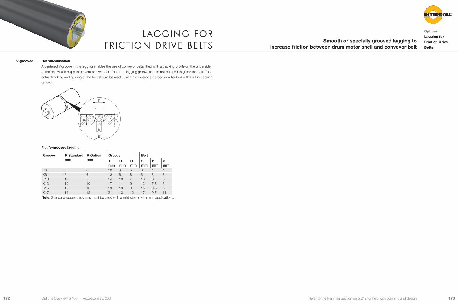
173172 Refer to the Planning Section on p 242 for help with planning and design
Hot vulcanisation
A centered V-groove in the lagging enables the use of conveyor belts fitted with a tracking profile on the underside
of the belt which helps to prevent belt wander. The drum lagging groove should not be used to guide the belt. The
actual tracking and guiding of the belt should be made using a conveyor slide bed or roller bed with built in tracking
grooves.
D
T
t
B
b
R d
Fig.: V-grooved lagging
Groove R Standard mm
R Optionmm
Groove Belt
Tmm
Bmm
Dmm
tmm
bmm
dmm
K6 8 6 10 8 5 6 4 4K8 8 6 12 8 6 8 5 5K10 10 8 14 10 7 10 6 6K13 12 10 17 11 9 13 7.5 8K15 12 10 19 13 9 15 9.5 8K17 14 12 21 13 12 17 9.5 11
Note: Standard rubber thickness must be used with a mild steel shell in wet applications.
V-grooved
laGGInG for fr ICtIon DrIve belts
Options
Lagging for
Friction Drive
Belts
Smooth or specially grooved lagging to increase friction between drum motor shell and conveyor belt
Options Overview p 166 Accessories p 200
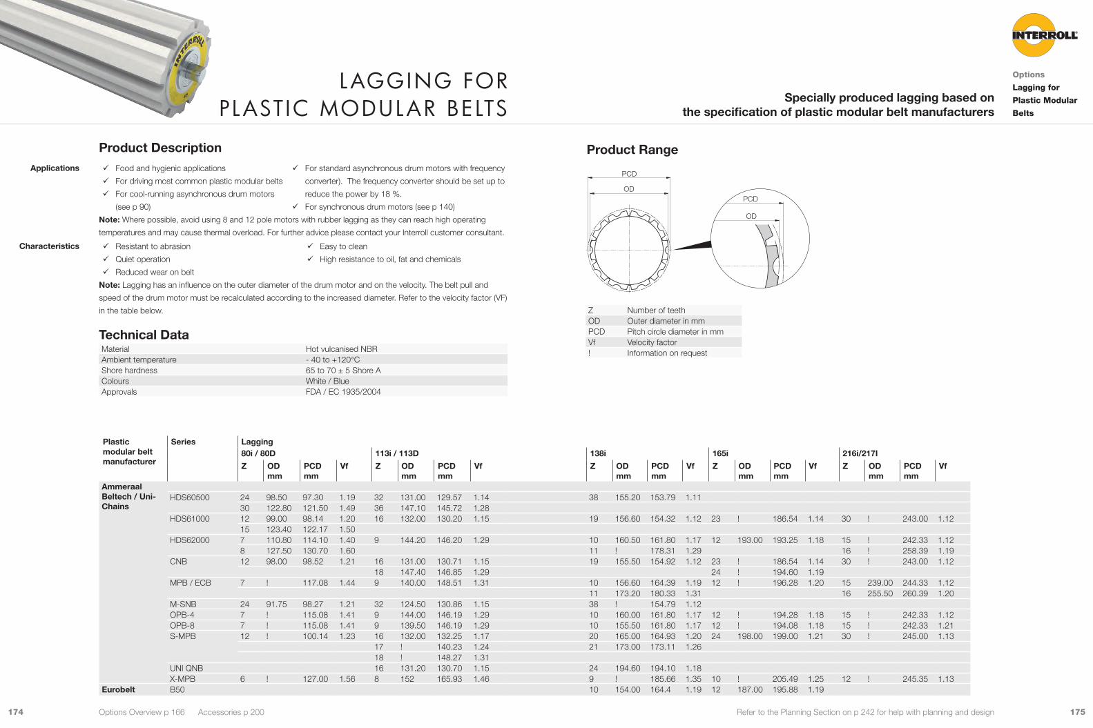
175174 Refer to the Planning Section on p 242 for help with planning and design
PCD
ODPCD
OD
Z Number of teethOD Outer diameter in mmPCD Pitch circle diameter in mmVf Velocity factor! Information on request
Product Description 9 Food and hygienic applications
9 For driving most common plastic modular belts
9 For cool-running asynchronous drum motors
(see p 90)
9 For standard asynchronous drum motors with frequency
converter). The frequency converter should be set up to
reduce the power by 18 %.
9 For synchronous drum motors (see p 140)
Note: Where possible, avoid using 8 and 12 pole motors with rubber lagging as they can reach high operating
temperatures and may cause thermal overload. For further advice please contact your Interroll customer consultant.
9 Resistant to abrasion
9 Quiet operation
9 Reduced wear on belt
9 Easy to clean
9 High resistance to oil, fat and chemicals
Note: Lagging has an influence on the outer diameter of the drum motor and on the velocity. The belt pull and
speed of the drum motor must be recalculated according to the increased diameter. Refer to the velocity factor (VF)
in the table below.
Technical DataMaterial Hot vulcanised NBRAmbient temperature - 40 to +120°CShore hardness 65 to 70 ± 5 Shore AColours White / BlueApprovals FDA / EC 1935/2004
Applications
Characteristics
laGGInG for plastIC moDular belts
Options
Lagging for
Plastic Modular
Belts
Specially produced lagging based on the specification of plastic modular belt manufacturers
Options Overview p 166 Accessories p 200
Plastic modular belt manufacturer
Series Lagging80i / 80D 113i / 113D 138i 165i 216i/217I
Z OD mm
PCD mm
Vf Z OD mm
PCD mm
Vf Z OD mm
PCD mm
Vf Z OD mm
PCD mm
Vf Z OD mm
PCD mm
Vf
Ammeraal Beltech / Uni-Chains
HDS60500 24 98.50 97.30 1.19 32 131.00 129.57 1.14 38 155.20 153.79 1.1130 122.80 121.50 1.49 36 147.10 145.72 1.28
HDS61000 12 99.00 98.14 1.20 16 132.00 130.20 1.15 19 156.60 154.32 1.12 23 ! 186.54 1.14 30 ! 243.00 1.1215 123.40 122.17 1.50
HDS62000 7 110.80 114.10 1.40 9 144.20 146.20 1.29 10 160.50 161.80 1.17 12 193.00 193.25 1.18 15 ! 242.33 1.128 127.50 130.70 1.60 11 ! 178.31 1.29 16 ! 258.39 1.19
CNB 12 98.00 98.52 1.21 16 131.00 130.71 1.15 19 155.50 154.92 1.12 23 ! 186.54 1.14 30 ! 243.00 1.1218 147.40 146.85 1.29 24 ! 194.60 1.19
MPB / ECB 7 ! 117.08 1.44 9 140.00 148.51 1.31 10 156.60 164.39 1.19 12 ! 196.28 1.20 15 239.00 244.33 1.1211 173.20 180.33 1.31 16 255.50 260.39 1.20
M-SNB 24 91.75 98.27 1.21 32 124.50 130.86 1.15 38 ! 154.79 1.12OPB-4 7 ! 115.08 1.41 9 144.00 146.19 1.29 10 160.00 161.80 1.17 12 ! 194.28 1.18 15 ! 242.33 1.12OPB-8 7 ! 115.08 1.41 9 139.50 146.19 1.29 10 155.50 161.80 1.17 12 ! 194.08 1.18 15 ! 242.33 1.21S-MPB 12 ! 100.14 1.23 16 132.00 132.25 1.17 20 165.00 164.93 1.20 24 198.00 199.00 1.21 30 ! 245.00 1.13
17 ! 140.23 1.24 21 173.00 173.11 1.2618 ! 148.27 1.31
UNI QNB 16 131.20 130.70 1.15 24 194.60 194.10 1.18X-MPB 6 ! 127.00 1.56 8 152 165.93 1.46 9 ! 185.66 1.35 10 ! 205.49 1.25 12 ! 245.35 1.13
Eurobelt B50 10 154.00 164.4 1.19 12 187.00 195.88 1.19
Product Range
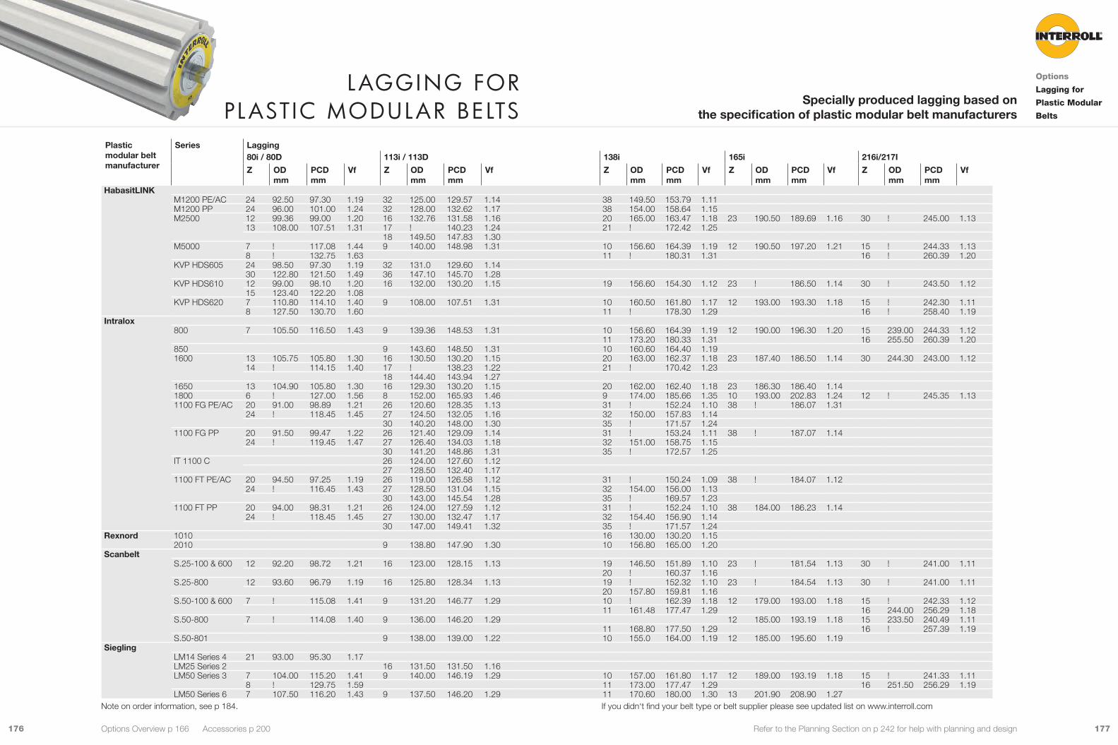
177176 Refer to the Planning Section on p 242 for help with planning and design
Plastic modular belt manufacturer
Series Lagging80i / 80D 113i / 113D 138i 165i 216i/217I
Z OD mm
PCD mm
Vf Z OD mm
PCD mm
Vf Z OD mm
PCD mm
Vf Z OD mm
PCD mm
Vf Z OD mm
PCD mm
Vf
HabasitLINKM1200 PE/AC 24 92.50 97.30 1.19 32 125.00 129.57 1.14 38 149.50 153.79 1.11M1200 PP 24 96.00 101.00 1.24 32 128.00 132.62 1.17 38 154.00 158.64 1.15M2500 12 99.36 99.00 1.20 16 132.76 131.58 1.16 20 165.00 163.47 1.18 23 190.50 189.69 1.16 30 ! 245.00 1.13
13 108.00 107.51 1.31 17 ! 140.23 1.24 21 ! 172.42 1.2518 149.50 147.83 1.30
M5000 7 ! 117.08 1.44 9 140.00 148.98 1.31 10 156.60 164.39 1.19 12 190.50 197.20 1.21 15 ! 244.33 1.138 ! 132.75 1.63 11 ! 180.31 1.31 16 ! 260.39 1.20
KVP HDS605 24 98.50 97.30 1.19 32 131.0 129.60 1.1430 122.80 121.50 1.49 36 147.10 145.70 1.28
KVP HDS610 12 99.00 98.10 1.20 16 132.00 130.20 1.15 19 156.60 154.30 1.12 23 ! 186.50 1.14 30 ! 243.50 1.1215 123.40 122.20 1.08
KVP HDS620 7 110.80 114.10 1.40 9 108.00 107.51 1.31 10 160.50 161.80 1.17 12 193.00 193.30 1.18 15 ! 242.30 1.118 127.50 130.70 1.60 11 ! 178.30 1.29 16 ! 258.40 1.19
Intralox800 7 105.50 116.50 1.43 9 139.36 148.53 1.31 10 156.60 164.39 1.19 12 190.00 196.30 1.20 15 239.00 244.33 1.12
11 173.20 180.33 1.31 16 255.50 260.39 1.20850 9 143.60 148.50 1.31 10 160.60 164.40 1.191600 13 105.75 105.80 1.30 16 130.50 130.20 1.15 20 163.00 162.37 1.18 23 187.40 186.50 1.14 30 244.30 243.00 1.12
14 ! 114.15 1.40 17 ! 138.23 1.22 21 ! 170.42 1.2318 144.40 143.94 1.27
1650 13 104.90 105.80 1.30 16 129.30 130.20 1.15 20 162.00 162.40 1.18 23 186.30 186.40 1.141800 6 ! 127.00 1.56 8 152.00 165.93 1.46 9 174.00 185.66 1.35 10 193.00 202.83 1.24 12 ! 245.35 1.131100 FG PE/AC 20 91.00 98.89 1.21 26 120.60 128.35 1.13 31 ! 152.24 1.10 38 ! 186.07 1.31
24 ! 118.45 1.45 27 124.50 132.05 1.16 32 150.00 157.83 1.1430 140.20 148.00 1.30 35 ! 171.57 1.24
1100 FG PP 20 91.50 99.47 1.22 26 121.40 129.09 1.14 31 ! 153.24 1.11 38 ! 187.07 1.1424 ! 119.45 1.47 27 126.40 134.03 1.18 32 151.00 158.75 1.15
30 141.20 148.86 1.31 35 ! 172.57 1.25IT 1100 C 26 124.00 127.60 1.12
27 128.50 132.40 1.171100 FT PE/AC 20 94.50 97.25 1.19 26 119.00 126.58 1.12 31 ! 150.24 1.09 38 ! 184.07 1.12
24 ! 116.45 1.43 27 128.50 131.04 1.15 32 154.00 156.00 1.1330 143.00 145.54 1.28 35 ! 169.57 1.23
1100 FT PP 20 94.00 98.31 1.21 26 124.00 127.59 1.12 31 ! 152.24 1.10 38 184.00 186.23 1.1424 ! 118.45 1.45 27 130.00 132.47 1.17 32 154.40 156.90 1.14
30 147.00 149.41 1.32 35 ! 171.57 1.24Rexnord 1010 16 130.00 130.20 1.15
2010 9 138.80 147.90 1.30 10 156.80 165.00 1.20Scanbelt
S.25-100 & 600 12 92.20 98.72 1.21 16 123.00 128.15 1.13 19 146.50 151.89 1.10 23 ! 181.54 1.13 30 ! 241.00 1.1120 ! 160.37 1.16
S.25-800 12 93.60 96.79 1.19 16 125.80 128.34 1.13 19 ! 152.32 1.10 23 ! 184.54 1.13 30 ! 241.00 1.1120 157.80 159.81 1.16
S.50-100 & 600 7 ! 115.08 1.41 9 131.20 146.77 1.29 10 ! 162.39 1.18 12 179.00 193.00 1.18 15 ! 242.33 1.1211 161.48 177.47 1.29 16 244.00 256.29 1.18
S.50-800 7 ! 114.08 1.40 9 136.00 146.20 1.29 12 185.00 193.19 1.18 15 233.50 240.49 1.1111 168.80 177.50 1.29 16 ! 257.39 1.19
S.50-801 9 138.00 139.00 1.22 10 155.0 164.00 1.19 12 185.00 195.60 1.19Siegling
LM14 Series 4 21 93.00 95.30 1.17LM25 Series 2 16 131.50 131.50 1.16LM50 Series 3 7 104.00 115.20 1.41 9 140.00 146.19 1.29 10 157.00 161.80 1.17 12 189.00 193.19 1.18 15 ! 241.33 1.11
8 ! 129.75 1.59 11 173.00 177.47 1.29 16 251.50 256.29 1.19LM50 Series 6 7 107.50 116.20 1.43 9 137.50 146.20 1.29 11 170.60 180.00 1.30 13 201.90 208.90 1.27
laGGInG for plastIC moDular belts
Options
Lagging for
Plastic Modular
Belts
Specially produced lagging based on the specification of plastic modular belt manufacturers
Options Overview p 166 Accessories p 200
Note on order information, see p 184. If you didn‘t find your belt type or belt supplier please see updated list on www.interroll.com
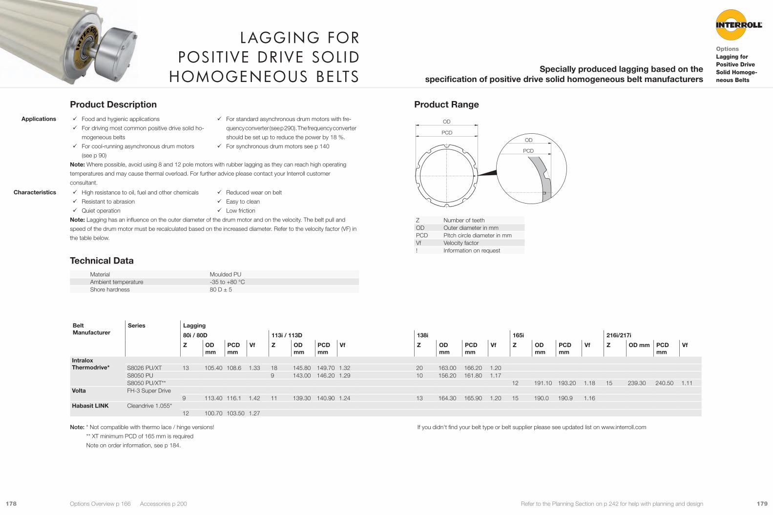
179178 Refer to the Planning Section on p 242 for help with planning and design
Product Range
PCD
ODPCD
OD
Z Number of teethOD Outer diameter in mmPCD Pitch circle diameter in mmVf Velocity factor! Information on request
Product Description 9 Food and hygienic applications
9 For driving most common positive drive solid ho-
mogeneous belts
9 For cool-running asynchronous drum motors
(see p 90)
9 For standard asynchronous drum motors with fre-
quency converter (see p 290). The frequency converter
should be set up to reduce the power by 18 %.
9 For synchronous drum motors see p 140
Note: Where possible, avoid using 8 and 12 pole motors with rubber lagging as they can reach high operating
temperatures and may cause thermal overload. For further advice please contact your Interroll customer
consultant.
9 High resistance to oil, fuel and other chemicals
9 Resistant to abrasion
9 Quiet operation
9 Reduced wear on belt
9 Easy to clean
9 Low friction
Note: Lagging has an influence on the outer diameter of the drum motor and on the velocity. The belt pull and
speed of the drum motor must be recalculated based on the increased diameter. Refer to the velocity factor (VF) in
the table below.
Technical DataMaterial Moulded PUAmbient temperature -35 to +80 °CShore hardness 80 D ± 5
Applications
Characteristics
laGGInG for posItIve DrIve sol ID
homoGeneous belts
OptionsLagging for Positive Drive Solid Homoge-neous Belts
Specially produced lagging based on the specification of positive drive solid homogeneous belt manufacturers
Options Overview p 166 Accessories p 200
Belt Manufacturer
Series Lagging
80i / 80D 113i / 113D 138i 165i 216i/217i
Z OD mm
PCDmm
Vf Z OD mm
PCD mm
Vf Z OD mm
PCD mm
Vf Z OD mm
PCD mm
Vf Z OD mm PCD mm
Vf
Intralox Thermodrive* S8026 PU/XT 13 105.40 108.6 1.33 18 145.80 149.70 1.32 20 163.00 166.20 1.20
S8050 PU 9 143.00 146.20 1.29 10 156.20 161.80 1.17S8050 PU/XT** 12 191.10 193.20 1.18 15 239.30 240.50 1.11
Volta FH-3 Super Drive9 113.40 116.1 1.42 11 139.30 140.90 1.24 13 164.30 165.90 1.20 15 190.0 190.9 1.16
Habasit LINK Cleandrive 1.055“12 100.70 103.50 1.27
Note: * Not compatible with thermo lace / hinge versions!
** XT minimum PCD of 165 mm is required
Note on order information, see p 184.
If you didn't find your belt type or belt supplier please see updated list on www.interroll.com

181180 Refer to the Planning Section on p 242 for help with planning and design
Product RangeTo use sprockets, drum motors have to be ordered with cylindrical shell and with key.
PCD
OD PCD
OD
PCD
PCDOD
OD
Z Number of teethOD Outer diameter in mmPCD Pitch circle diameter in mmVf Velocity factorB Width of sprocket in mmRev. Reversible sprocket Art. No. Article number! Information on request
Product Description 9 For driving most common plastic modular belts
9 For standard asynchronous drum motors with fre-
quency converter (see p 290). The frequency converter
should be set up to reduce the power by 18 %.
9 For cool-running asynchronous drum motors
(see p 90)
9 For drum motors with cylindrical shell and key
9 For food processing applications
9 For synchronous drum motors (see p 140)
9 Laser cut for excellent fitting accuracy 9 Rust-free with stainless steel sprockets
Note: The sprockets have an influence on the outer diameter of the drum motor and on the velocity. The belt pull
and speed of the drum motor must be recalculated according to the increased diameter. Refer to the velocity factor
(VF) in the table below.
Fixed sprockets are available on request. Only one fixed sprocket per drum motor should be fitted to allow for belt
expansion.
Technical DataMaterial Steel, stainless steel
Mild steelAmbient temperature -30 to +120 °C
Applications
Characteristics
sproCkets for plastIC moDular belts
Options
Sprockets for
Plastic Modular
Belts
Special sprockets based on the specification of modular belt manufacturers
Options Overview p 166 Accessories p 200
Modular belt manufacturer
Series Rev. Sprocket
80i / 80D 113i / 113D 138i 165i
Z OD mm
PCDmm
Vf B mm
Art. No. Z OD mm
PCD mm
Vf B mm
Art. No. Z OD mm
PCD mm
Vf B mm
Art. No. Z OD mm
PCD mm
Vf B mm
Art. No.
HabasitLINKM1185 9 32 136.30 137.00 1.21 6.0 1100024 M1220 9 25 103.70 101.00 1.24 3.00 1001631 36 150.20 149.80 1.33 3.00 1001638 M1233 9 40 166.89 162.00 1.18 3.00 1100310 M2520 & M2530
9 15 123.90 122.00 1.49 12.00 61008303 19 156.80 154.00 1.36 12.00 61104053 13 107.40 107.00 1.31 4.00 1001635 17 141.03 139.00 1.23 4.00 1001641 20 165.53 164.00 1.20 6.00 1001648 24 198.62 196.00 1.21 6.00 1001653 15 123.90 122.00 1.49 4.00 1004342 19 156.80 154.00 1.36 4.00 1001612
M2540 20 165.10 164.00 1.45 4.00 1000273 20 165.22 163.00 1.19 6.00 1100290M5010 9 10 157.20 164.00 1.45 5.00 1100644 11 174.30 180.00 1.31 5.00 1100645 M5020 11 173.80 180.00 1.31 5.00 1100646 M5032 10 157.04 164.00 1.45 6.00 1100647

183182 Refer to the Planning Section on p 242 for help with planning and design
Modular belt manufacturer
Series Rev. Sprocket
80i / 80D 113i / 113D 138i 165i
Z OD mm
PCDmm
Vf B mm
Art. No. Z OD mm
PCD mm
Vf B mm
Art. No. Z OD mm
PCD mm
Vf B mm
Art. No. Z OD mm
PCD mm
Vf B mm
Art. No.
Intralox200 12 197.55 196 1.43 4.00 1003373 400 12 194.20 196.00 1.43 3.00 1100688800 9 8 124.24 133.00 1.63 6.00 1100655 10 158.32 164.00 1.45 6.00 1001642 12 190.00 196.00 1.43 6.00 1001647 22 206.31 208.00 1.28 6.00 1100684 900 9 12 107.00 105.00 1.29 3.00 1001603 15 135.00 131.00 1.16 3.00 1001608 20 178.00 174.00 1.27 3.00 1001621 22 194.25 191.00 1.18 3.00 1001628
18 160.00 157.00 1.39 3.00 1001611 24 213.60 208.00 1.28 3.00 1100656 21 186.90 182.00 1.33 3.00 1003372
1000 9 22 112.00 107.10 1.31 4.00 1100381 1100 9 24 118.46 116.00 1.42 18.00 61101976 30 147.90 145.00 1.28 18.00 61005606
24 118.46 119.00 0.87 6.00 1001634 32 157.69 155.00 1.37 18.00 61101908 35 172.48 173.00 1.26 4.00 6110406030 147.90 145.00 1.28 6.00 1001615
24 118.46 116.00 1.42 6.00 1001632 32 157.69 155.00 1.37 6.00 1001617 35 172.48 173.00 1.26 4.00 1001626 197.12 194.00 1.20 4.00 1100648 1100 Flat Top 9 35 172.48 170.00 1.24 8.00 61104054 1400 9 21 173.66 170.00 1.24 6.00 1100649 1500 9 28 118.84 113.00 1.38 6.00 1001637 36 152.79 146.00 1.29 6.00 1001643 42 173.74 170.00 1.24 6.00 1100650
30 124.10 121.00 1.48 6.00 1100651 1600 9 14 111.80 114.00 1.40 8.00 1003371 17 135.30 138.00 1.22 8.00 1001640 20 162.17 162.00 1.18 8.00 1001623 12 191.37 192.00 1.19 8.00 61010643
20 162.17 162.00 1.43 8.00 61010635 2000 9 16 149.34 165.00 1.46 8.00 1100652 2200 9 16 198.00 195.00 1.42 16.00
61104055 16 198.00 195.00 1.42 8.00 1100293 18 222.80 219.00 1.60 8.00 1100653
2400 9 15 122.40 122.00 1.49 12.00 61104057 19 154.60 154.00 1.36 12.00 61102085 24 194.95 195.00 1.42 12.00 61104056 14 114.24 115.00 1.41 12.00 61104059 14 114.24 115.00 1.41 6.00 1100682 16 130.40 130.00 1.59 6.00 61010634 17 138.69 138.00 1.69 6.00 1100654 15 122.40 122.00 1.49 6.00 1001604 19 154.60 154.00 1.36 6.00 1001613 24 194.95 195.00 1.42 6.00 1001625 26 211.55 211.00 1.30 6.00 1001629
RexnordFT 815 9880 9 25 154.20 155.00 1.37 8.00 1100686 15 184.25 183.00 1.34 10.00 1100658 1010 16 131.50 130.00 1.59 8.00 1100657 8506 9 21 130.00 ! ! 11.00 61104058
21 130.00 130.00 1.59 11.00 61104061 21 130.00 130.00 1.59 3.00 1100687
ScanbeltS.12-400 9 28 117.90 112.00 1.37 4.00 1100659 36 149.78 143.88 1.27 4.00 1100257 S.25-100 14 113.07 112.00 1.37 4.00 1100441 S.25-400 9 13 104.97 104.00 1.27 4.00 1100138 17 139.23 136.00 1.20 4.00 1100136 20 159.31 160.00 1.17 4.00 1100660 S.25-830 9 20 156.79 160.00 1.17 8.00 1100134 S.50-100 9 12 187.55 195.00 1.42 4.00 1100160S.50-808 9 10 164.00 164.00 1.45 8.00 61010638 S.50-908 9 13 216.35 209.00 1.29 8.00 1100661
sproCkets for plastIC moDular belts
Options
Sprockets for
Plastic Modular
Belts
Special sprockets based on the specification of modular belt manufacturers
Options Overview p 166 Accessories p 200
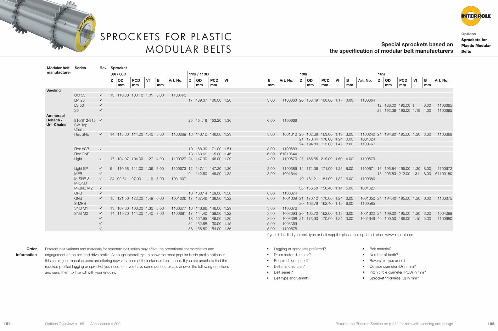
185184 Refer to the Planning Section on p 242 for help with planning and design
Different belt variants and materials for standard belt series may affect the operational characteristics and
engagement of the belt and drive profile. Although Interroll trys to show the most popular basic profile options in
this catalogue, manufacturers are offering new variations of their standard belt series. If you are unable to find the
required profiled lagging or sprocket you need, or if you have some doubts, please answer the following questions
and send them to Interroll with your enquiry:
Modular belt manufacturer
Series Rev. Sprocket
80i / 80D 113i / 113D 138i 165i
Z OD mm
PCDmm
Vf B mm
Art. No. Z OD mm
PCD mm
Vf B mm
Art. No. Z OD mm
PCD mm
Vf B mm
Art. No. Z OD mm
PCD mm
Vf B mm
Art. No.
SieglingCM 25 9 13 110.00 108.12 1.35 3.00 1100662 LM 25 9 17 139.37 136.00 1.20 3.00 1100663 20 163.49 160.00 1.17 3.00 1100664 LS 50 9 12 186.00 195.00 ! 6.00 1100665 S5 9 23 192.36 193.00 1.19 4.00 1100685
Ammeraal Beltech / Uni-Chains
810/812/815 Slat Top Chain
9 25 154.18 153.20 1.36 6.00 1100666
Flex SNB 9 14 113.80 114.00 1.40 3.00 1100669 18 146.10 146.00 1.29 3.00 1001610 20 162.36 163.00 1.19 3.00 1100242 24 194.80 195.00 1.20 3.00 1100668 21 170.44 170.00 1.24 3.00 1001624 24 194.80 195.00 1.42 3.00 1100667
Flex ASB 9 10 168.30 171.00 1.51 8.00 1100683 Flex ONE 13 163.60 165.00 1.46 6.00 61010644Light 9 17 104.97 104.00 1.27 4.00 1100027 24 147.30 146.00 1.29 4.00 1100670 27 165.65 219.00 1.60 4.00 1100679
Light EP 9 9 110.58 111.00 1.36 8.00 1100673 12 147.11 147.20 1.30 8.00 1100389 14 171.36 171.00 1.25 8.00 1100671 16 195.84 195.00 1.20 8.00 1100672 MPB 9 9 142.50 149.00 1.32 8.00 1001644 13 205.83 212.00 131 8.00 61100180 M-SNB & M-QNB
9 24 99.51 97.00 1.19 5.00 1001607 40 181.21 181.00 1.32 6.00 1100380
M-SNB M2 9 38 156.50 156.40 1.14 5.00 1001627 OPB 9 10 160.14 169.00 1.50 8.00 1100674 QNB 9 15 121.50 122.00 1.49 6.00 1001606 17 137.46 138.00 1.22 6.00 1001609 21 170.12 170.00 1.24 6.00 1001650 24 194.40 195.00 1.20 6.00 1100675 S-MPB 20 163.79 162.40 1.19 6.00 1100585 SNB M1 9 13 107.80 106.00 1.30 3.00 1100677 18 148.66 146.00 1.29 3.00 1100676 SNB M2 9 14 119.20 114.00 1.40 3.00 1100681 17 144.40 138.00 1.22 3.00 1003093 20 165.70 162.00 1.18 3.00 1001622 24 199.00 195.00 1.20 3.00 1004089
9 18 152.95 146.00 1.29 3.00 1003368 21 173.90 170.00 1.24 3.00 1001649 46 190.50 186.00 1.15 5.00 1100680 9 32 132.68 130.00 1.15 5.00 1003369 9 38 156.50 154.00 1.36 5.00 1100678
• Lagging or sprockets preferred?
• Drum motor diameter?
• Required belt speed?
• Belt manufacturer?
• Belt series?
• Belt type and variant?
• Belt material?
• Number of teeth?
• Reversible, yes or no?
• Outside diameter (D) in mm?
• Pitch circle diameter (PCD) in mm?
• Sprocket thickness (B) in mm?
sproCkets for plastIC moDular belts
Options
Sprockets for
Plastic Modular
Belts
Special sprockets based on the specification of modular belt manufacturers
Options Overview p 166 Accessories p 200
Order
Information
If you didn't find your belt type or belt supplier please see updated list on www.interroll.com

187186 Refer to the Planning Section on p 242 for help with planning and design
Product RangeTo use these sprockets, D-series Drum Motors or Idlers must be ordered with hexagonal (6 sided) shell
(see p 150.)
PCD
ODPCD
OD
Z Number of teethOD Outer diameter in mmPCD Pitch circle diameter in mmVf Velocity factorB Width of sprocket in mmRev. Reversible sprocket Art. No. Article number! Information on request
Product Description 9 For Synchronous Drum Motor 88D see p 150
9 For food processing and hygienic applications
9 For driving plastic modular belts
9 High resistance to cleaning chemicals in food
processing
9 High resistance to oil, fuel and other chemicals
9 Resistant to abrasion
9 Quiet operation
9 Easy to clean and replace
9 Low friction
Note: The sprockets have an influence on the outer diameter of the drum motor and on the velocity. The belt pull
and speed of the drum motor must be recalculated according to the increased diameter. Refer to the velocity factor
(VF) in the table below.
Technical DataMaterial Stainless steelOptions All common belt manufacturers‘ sprockets available to order
Electropolished to hygienic surface roughness (Ra<= 0.8 um) on requestAmbient temperature -30 to + 120 °C
Applications
Characteristics
sproCkets for plastIC moDular belts for use WIth
Drum motor or IDler 88D Options
Sprockets for
88D
Special sprockets based on the specification of modular belt manufacturers
Options Overview p 166 Accessories p 200
Modular belt manufacturer
Series Rev. Sprocket
88D
Z OD mm
PCDmm
Vf B mm
Art. No.
Intralox1600 9 16 128.55 128.55 1.26 10.00 1100711

189188 Refer to the Planning Section on p 242 for help with planning and design
Balancing
Product Description
Static or dynamic balancing of the drum motor reduces vibration and out of balance running for sensitive high
speed or dynamic weighing applications. Static balancing is applied to the drum motor shell only and the effective
result must be tested for each application. Dynamic balancing includes the drum motor rotor, shell and end
housings and the effective balance is given in the table below.
9 High-speed conveyors
9 Weighing equipment
9 For asynchronous drum motors only
9 For i-series only
9 Not for AC-PM synchronous motors
Note: Any external modifications, like fixtures, lagging or sprockets, have an impact on the imbalance.
Note: For dynamic balancing please choose only i-series drum motors with stainless steel end housings.
Technical Data
Dynamic balancing 3 g, 5 g, 8 g, 10 gTolerance ±2 gEnd housing Solid stainless steel 80i end housing 1 oil plug only suppliedShell lagging material Only hot vulcanised NBR may be used
Note: Max. balancing length SL ≤ 800 mm.
Applications
Backstops
Product Description
Backstops prevent roll-back of the belt and load.
9 Single direction inclined belt conveyors
9 For preventing run-back of the belt and load when
the power supply is off
9 Only for asynchronous drum motors
9 Not for AC-PM synchronous motors
9 Not for Interroll Drum Motor 113S
9 Bearing runs only in one direction
9 Fitted to the rotor shaft, except 80i
9 Fitted in the end housing on the 80i
9 No electrical connection necessary
9 Higher holding torque than an electromagnetic
brake
The rotational direction of the drum motor with backstop is indicated by an arrow on the bearing housing on the
electrical connection side.
Fig.: Rotation arrow
Product Range
Rotational direction looking from the connector side Clockwise (standard)Counter-clockwise
Applications
Characteristics
b a C k s to p s a n D b a l a n C I n GOptions
Backstops/
Balancing
Options Overview p 166 Accessories p 200

191190 Refer to the Planning Section on p 242 for help with planning and design
Product Range Drum Motor
Rated torque M
Rated power
Rated voltage
Rated current
DC swit-ching t1
AC swit-ching t1
Opening delay time t2
Nm W V DC A ms ms ms113i 6 24 24 1.00 26 200 30138i 6 24 24 1.00 26 200 30165i to 216i 12 33 24 1.38 46 260 4080i 1.1 12 24 0.5 13 80 20113i 6 24 104 0.23 26 200 30138i 6 24 104 0.23 26 200 30165i to 216i 12 33 104 0.32 46 260 40217i 26 50 104 0.48 60 500 60315i 50 70 104 0.67 100 700 8080i 1.1 12 104 0.12 13 80 20113i 6 24 207 0.12 26 200 30138i 6 24 207 0.12 26 200 30165i to 216i 12 33 207 0.16 46 260 40217i 26 50 207 0.24 60 500 60315i 50 70 207 0.34 100 700 80
Product DescriptionBrakes and holds a load according to the stated belt pull.
9 For reversible inclined and declined conveyors
9 For reduced stopping times *
9 For stopping and holding loads
9 For approximate positioning *
9 Asynchronous drum motors only
9 For synchronous drum motors see p 192
* For faster stopping times and accurate positioning, please use a frequency converter with braking function and if
necessary an encoder with feed back control.
9 Low-noise
9 Low-wear
9 Operated by rectifier (see p 194)
9 Applied to the drum motor‘s rotor shaft
9 When power to the motor is disrupted the brake will
close (the brake is naturally closed)
The brake opening and closing response time can vary substantially depending on the following:
• Type and viscosity of the oil
• Level of oil in the drum motor
• Ambient temperature
• Internal motor working temperature
• Switching at input (AC-switching) or at output (DC-switching)
The difference between AC switching and DC switching is shown in the following table:
AC switching DC switching Closing response time slow fastBrake voltage approx. 1 V approx. 500 V
Note: For DC-switching, the switching contacts must be protected against damage due to high voltage.
t 1 t 2
M
t
Fig.: Closing and opening response time
t1 Closing response time
t2 Opening response time
The rated brake torque is strongly influenced by the operating conditions within the drum motor (operation in oil at
high temperatures) and the ambient temperature. For reasons of safety, the brake torque given in the data sheets
should be reduced by 50 % for load calculations.
Applications
Characteristics
Response time
Reduction of
brake torque
eleCtromaGnetIC brakes Options
Electromagnetic
Brakes
Options Overview p 166 Accessories p 200
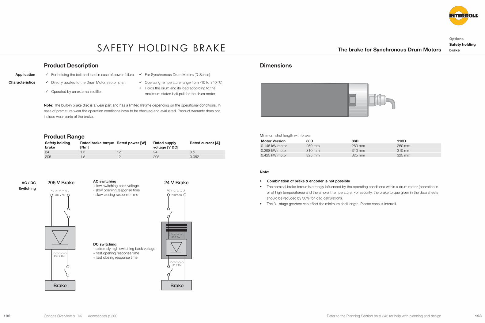
193192 Refer to the Planning Section on p 242 for help with planning and design
Dimensions
Minimum shell length with brake
Motor Version 80D 88D 113D0.145 kW motor 260 mm 260 mm 260 mm0.298 kW motor 310 mm 310 mm 310 mm0.425 kW motor 325 mm 325 mm 325 mm
Note:
• Combination of brake & encoder is not possible
• The nominal brake torque is strongly influenced by the operating conditions within a drum motor (operation in
oil at high temperatures) and the ambient temperature. For security, the brake torque given in the data sheets
should be reduced by 50% for load calculations.
• The 3 - stage gearbox can affect the minimum shell length. Please consult Interroll.
Product Description 9 For holding the belt and load in case of power failure 9 For Synchronous Drum Motors (D-Series)
9 Directly applied to the Drum Motor‘s rotor shaft
9 Operated by an external rectifier
9 Operating temperature range from -10 to +40 °C
9 Holds the drum and its load according to the
maximum stated belt pull for the drum motor
Note: The built-in brake disc is a wear part and has a limited lifetime depending on the operational conditions. In
case of premature wear the operation conditions have to be checked and evaluated. Product warranty does not
include wear parts of the brake.
Product RangeSafety holding brake
Rated brake torque [Nm]
Rated power [W] Rated supply voltage [V DC]
Rated current [A]
24 1.5 12 24 0.5205 1.5 12 205 0.052
230 V AC
205 V DC
N L
205 V Brake
Brake
AC switching+ low switching back voltage- slow opening response time- slow closing response time 230 V AC
24 V DC
24 V AC
N L
24 V Brake
Brake
DC switching- extremely high switching back voltage+ fast opening response time+ fast closing response time
Application
Characteristics
AC / DC
Switching
safety holDInG brakeOptions
Safety holding
brakeThe brake for Synchronous Drum Motors
Options Overview p 166 Accessories p 200

195194 Refer to the Planning Section on p 242 for help with planning and design
DimensionsHalf-wave rectifier and bridge rectifier
19
C
E
BD
A
Reference number
Amm
Bmm
Cmm
Dmm
Emm
1001440 34 30 25 3.5 4.51001441 64 30 54 4.5 5
Phase rectifier
1 2 3 4 5 6
549
9
30
5
4.5
1 2 3 4 65
48.6
4.554
5.6
15
64 17.5
Fig.: 1001442
Product Description 9 Drum motors with electromagnetic brake (see p 190)
9 Applications with frequent starts and stops
9 Positioning applications
9 Half-wave and bridge rectifier for standard applica-
tions
9 Fast acting and multiswitch rectifier for applications
in which short opening delay times are necessary
9 Not for S-series
9 For i- and D- series motors
9 External component, must be covered or installed
in a control box as close to the brake as possible.
Product RangeInput voltage
Brake voltage
Starting voltage
Holding voltage
Version Applica-tion
Art. No
V AC V DC V DC V DC 115 104 104 52 Fast acting rectifier A
B61011343*
230 207 207 104 Fast acting rectifier AB
61011343
230 104 104 104 Half wave rectifierBridge rectifier
AB
1001440
230 104 190 52 Phase rectifier A 1001442400 104 180 104 Multiswitch A
B1003326
460 104 180 104 Multiswitch A 1003326460 207 207 207 Half wave rectifier
Bridge rectifierAB
1001441*
A Continuous running applicationB Frequent start/stop application
Using a fast acting rectifier or a phase rectifier will save energy because the holding voltage is lower than the
starting voltage.
Note: Screened cables should be used to protect against EMI
* = also useable for D-Series
Applications
Characteristics
reCtIf Iers Options
RectifiersThe rectifier operates the electromagnetic brake
Options Overview p 166 Accessories p 200

197196 Refer to the Planning Section on p 242 for help with planning and design
Fast acting rectifier
64
48.6
8 7 6 5 4 3 2 1
15
54
5.6
Ø
8 7 6 5 4 3 2 130
5
4.5
4.5
549
9
17.5
Fig.: 61011343
Multiswitch
ON
1 2 3 4
17.5
54
55.6
9
3073
.6
15
64
69
Ø4.5
544.5
Fig.: 1003326
reCtIf Iers Options
RectifiersThe rectifier operates the electromagnetic brake
Options Overview p 166 Accessories p 200
Connection DiagramInterroll recommends installing a switch between (3) and (4) for fast brake release.
1 2 3 4 5 6
input bridge brake
Fig.: Half-wave rectifier
1 2 3 4 5 6
input bridge brake
Fig.: Bridge rectifier
1 2 3 4 5 6
ekarb tupni
Fig.: Phase rectifier
input bridge brake justage delay time
1 2 3 4 5 6 7 8
Fig.: Fast acting rectifier
Fig.: Multiswitch

199198 Refer to the Planning Section on p 242 for help with planning and design
SKF 32 or 48 incremental encoderPower supply Vdd = 5 to 24 VPower consumption max. 20 mAElectrical interface Open collector NPNOutput increments A, B Increments resolution 32 or 48 pulses / revolutionNecessary Pull-up resistor 270 to 1,500 Ω (see connection diagram section)Max. cable length 10 m
RLS incremental encoderPower supply Vdd = 5 V ± 5 %Power consumption 35 mAElectrical interface RS422Output increments A, B, Z, A-, B-, Z-Increments resolution 64 ... 1,024 pulses / revolution
2,048 pulses / revolution (max speed 2,500 rpm)Max. cable length 5 m
LTN ResolverInput voltage and current range 7 VInput frequency range 5 kHz / 10 kHzInput current 58 mA / 36 mANumber of poles 2Transformation ratio 0.5 ± 10 %Max. cable length 10 m
SKS36 hiperface (Sick/Stegman)Power supply 7 to 12 V (recommended 8 V)Power consumption max. 60 mAData transfer HiperfaceSerial data RS485Single turn resolution 4,096 positions / revolutionSine/cosine periods per revolution 128Max. cable length 10 m
Product Description 9 For applications which require control and monito-
ring of speed, direction, and position of the drum
motor belt or load
9 Enables closed loop system control
9 For i-series and D-series only
9 Cannot be combined with a brake or backstop
option
9 Supplies low to high resolution signals to an
external control unit
9 Incremental or absolute encoders
9 Coupled to rotor shaft or embedded in the rotor
bearing
Note: Not available for i-series with dual voltage.
Product Range All resolutions and speeds given in the following product range are referring to the rotor shaft. The drum motor gear
ratio must be considered to find the values related to the drum shell.
Encoder types Asynchronous Drum Motors Synchronous Drum Motors
Connection diagram references (see p 316 )
80i 113i 138i 165i 216i 217i 80D 88D 113DSKF 32 incremental encoder *
32 pulses 9 9 9 70
SKF 48 incremental encoder
48 pulses 9 9 9 70
RLS incremental encoder *
64 to 1,024 pulses 9 9 9 9 9 9 9 9 9 71
LTN Resolver 2 poles resolver 9 9 9 9 72SKS36 Hiperface
Single turn absolute hiperface high resolution 9 9 9 73
Note: * For 80i with encoder the drum motor will be supplied with 25 mm diameter shafts and one supply voltage.
Other feedback devices and resolutions on request.
Application
Characteristics
feeDbaCk DevICesOptions
Feedback
Devices
Options Overview p 166 Accessories p 200

201200 Refer to the Planning Section on p 242 for help with planning and design
a C C e s s o r I e s 9 Accessories help you integrate the Interroll Drum Motor into your material handling system quickly and efficiently.
9 This chapter includes external accessories which can be added to the Interroll Drum Motor during or after installation.
Accessories
Overview
Standard Asynchronous Drum Motors p 12 Cool-Running Asynchronous Drum Motors p 90 Options p 166 Synchronous Drum Motors p 140
 Mounting BracketsAnti-vibration bracket p 202Light-duty flanged bracket for drum motor p 204Light-duty flanged bracket for idler pulley p 206Heavy-duty flanged bracket, Aluminium p 208Heavy-duty flanged bracket, PE p 212Plummer block for drum motor and idler p 216
 Idler PulleysIdler pulley with integral bearing p 218Idler pulley without bearing Series 7000 p 224Idler pulley with bearing Series 7000 p 226
 Drive PulleysDrive pulley without bearing Series 7000 p 228Drive pulley with bearing Series 7000 p 230
 Conveyor RollersConveyor Roller Series 1450 p 232Universal Conveyor Roller Series 1700 p 234
 IFI-IP55 Frequency Inverter p 238
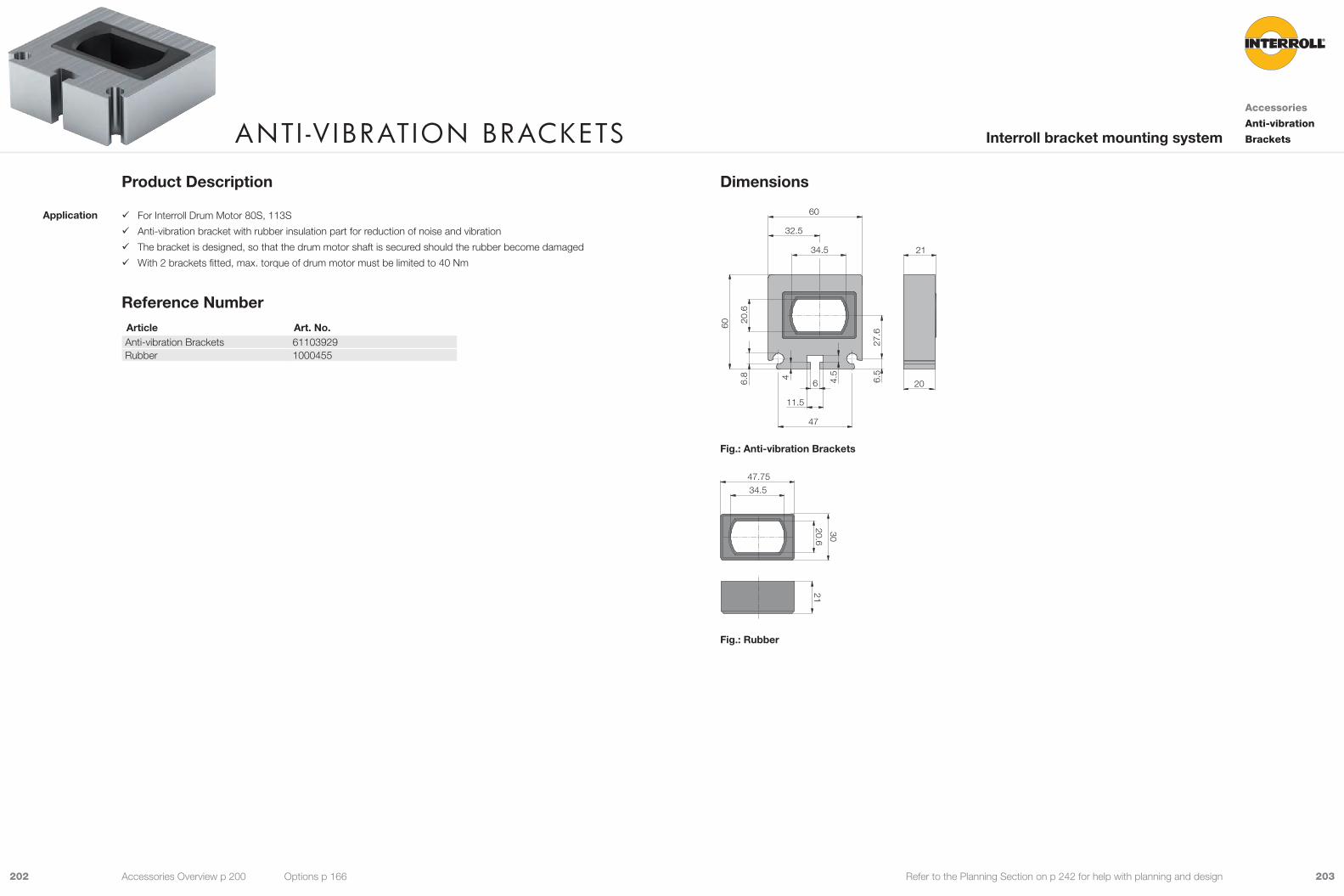
203202 Refer to the Planning Section on p 242 for help with planning and design
Dimensions
6.8 4 6.5
47
20
34.5
20.6
27.6
60
60
21
32.5
11.5
6 4.5
Fig.: Anti-vibration Brackets
47.7534.5
30
2120.6
Fig.: Rubber
Product Description
9 For Interroll Drum Motor 80S, 113S
9 Anti-vibration bracket with rubber insulation part for reduction of noise and vibration
9 The bracket is designed, so that the drum motor shaft is secured should the rubber become damaged
9 With 2 brackets fitted, max. torque of drum motor must be limited to 40 Nm
Reference NumberArticle Art. No.Anti-vibration Brackets 61103929Rubber 1000455
Application
antI -v IbratIon braCketsAccessories
Anti-vibration
BracketsInterroll bracket mounting system
Accessories Overview p 200 Options p 166

205204 Refer to the Planning Section on p 242 for help with planning and design
Dimensions
F E D A
C
B
I
A
G
H
Shaft mm
A mm
B mm
C mm
D mm
E mm
F mm
G mm
H mm
I mm
20.0 x 25.0 75.0 55.0 25.3 45.5 20.3 20.3 3.0 6.5 15.021.0 x 35.0 75.0 55.0 35.5 45.5 26.5 21.5 3.0 6.5 15.0
Product Description
9 For Interroll Drum Motor 80S, 113S
Product RangeDrum Motor Shaft Material Art. No.
mm 80S / 113S 21 x 35 Steel, stainless steel 61103896113S 20 x 25 Steel, stainless steel 61103897
Note: Shaft 20 x 25 non standard, special order only.
Application
l IGht Duty flanGeD braCket for Drum motor
Accessories
Mounting
BracketsSet of brackets for mounting a drum motor
Accessories Overview p 200 Options p 166
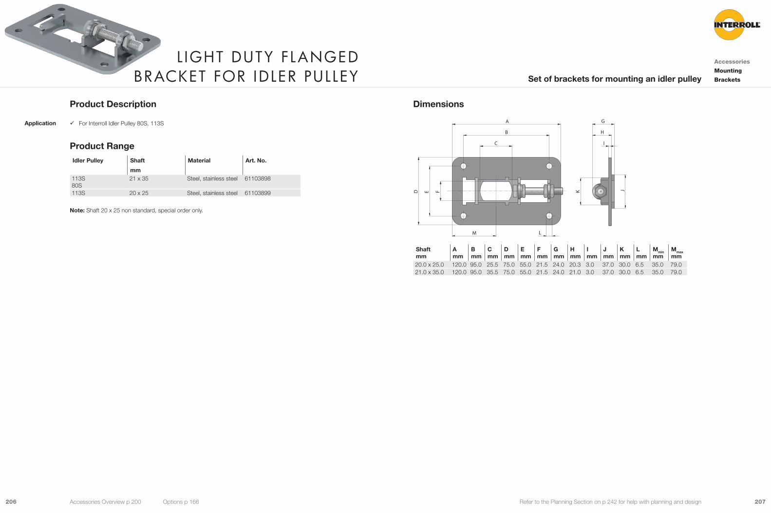
207206 Refer to the Planning Section on p 242 for help with planning and design
Dimensions
FED J
C
B
A G
LM
K
H
I
Shaft mm
A mm
Bmm
C mm
D mm
Emm
Fmm
Gmm
H mm
I mm
J mm
K mm
L mm
Mmin
mmMmax
mm20.0 x 25.0 120.0 95.0 25.5 75.0 55.0 21.5 24.0 20.3 3.0 37.0 30.0 6.5 35.0 79.021.0 x 35.0 120.0 95.0 35.5 75.0 55.0 21.5 24.0 21.0 3.0 37.0 30.0 6.5 35.0 79.0
Product Description
9 For Interroll Idler Pulley 80S, 113S
Product RangeIdler Pulley Shaft Material Art. No.
mm 113S80S
21 x 35 Steel, stainless steel 61103898
113S 20 x 25 Steel, stainless steel 61103899
Note: Shaft 20 x 25 non standard, special order only.
Application
l IGht Duty flanGeD braCket for IDler pulley
Accessories
Mounting
BracketsSet of brackets for mounting an idler pulley
Accessories Overview p 200 Options p 166
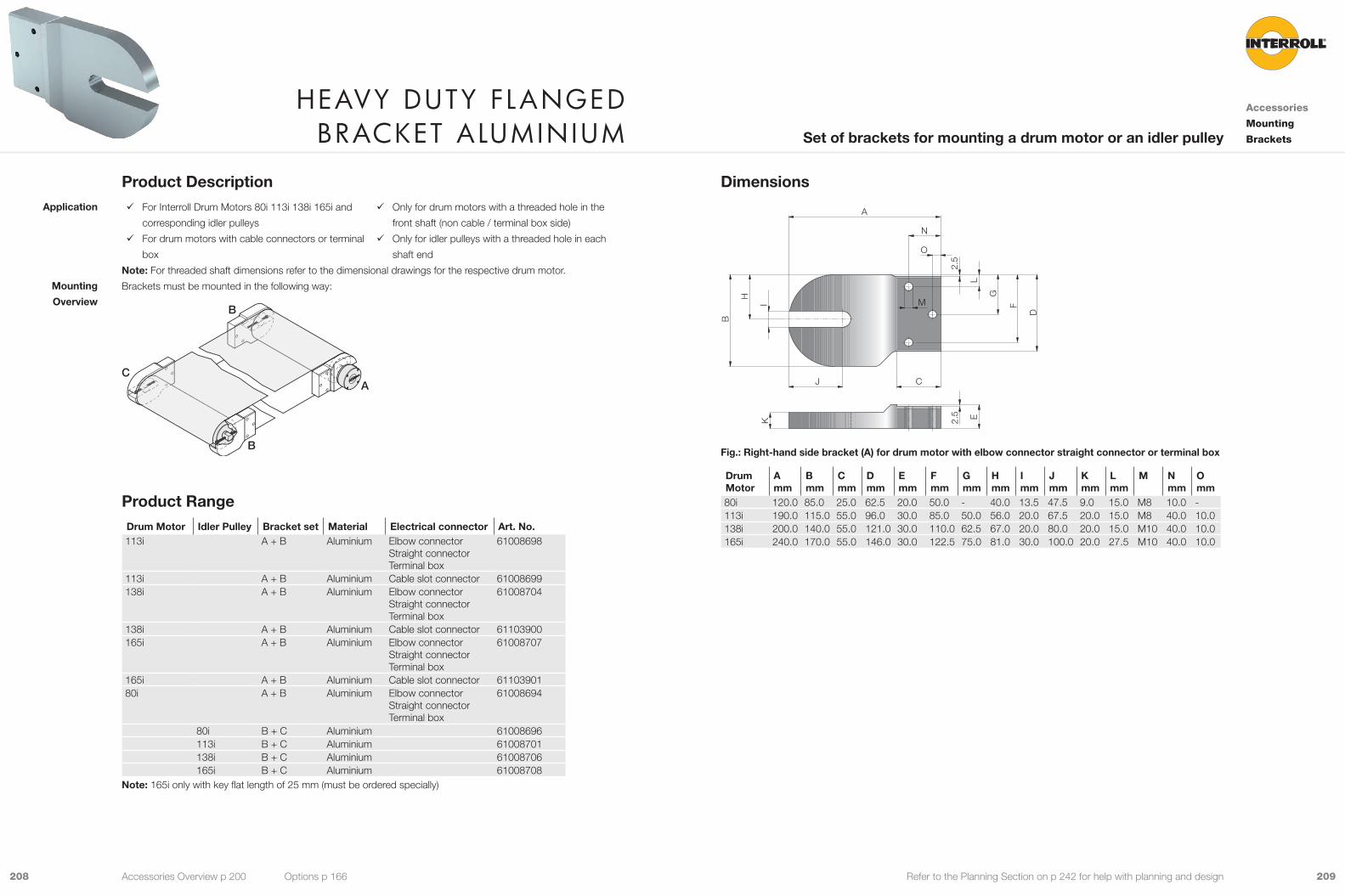
209208 Refer to the Planning Section on p 242 for help with planning and design
Dimensions
2.5
L
G
F
D
O
N
I
H
B
K
J
A
2.5 E
C
M
Fig.: Right-hand side bracket (A) for drum motor with elbow connector straight connector or terminal box
Drum Motor
A mm
B mm
C mm
D mm
E mm
F mm
G mm
H mm
I mm
J mm
K mm
L mm
M N mm
O mm
80i 120.0 85.0 25.0 62.5 20.0 50.0 - 40.0 13.5 47.5 9.0 15.0 M8 10.0 -113i 190.0 115.0 55.0 96.0 30.0 85.0 50.0 56.0 20.0 67.5 20.0 15.0 M8 40.0 10.0138i 200.0 140.0 55.0 121.0 30.0 110.0 62.5 67.0 20.0 80.0 20.0 15.0 M10 40.0 10.0165i 240.0 170.0 55.0 146.0 30.0 122.5 75.0 81.0 30.0 100.0 20.0 27.5 M10 40.0 10.0
Product Description 9 For Interroll Drum Motors 80i 113i 138i 165i and
corresponding idler pulleys
9 For drum motors with cable connectors or terminal
box
9 Only for drum motors with a threaded hole in the
front shaft (non cable / terminal box side)
9 Only for idler pulleys with a threaded hole in each
shaft end
Note: For threaded shaft dimensions refer to the dimensional drawings for the respective drum motor.
Brackets must be mounted in the following way:
B
C
B
A
Product RangeDrum Motor Idler Pulley Bracket set Material Electrical connector Art. No.113i A + B Aluminium Elbow connector
Straight connectorTerminal box
61008698
113i A + B Aluminium Cable slot connector 61008699138i A + B Aluminium Elbow connector
Straight connectorTerminal box
61008704
138i A + B Aluminium Cable slot connector 61103900165i A + B Aluminium Elbow connector
Straight connectorTerminal box
61008707
165i A + B Aluminium Cable slot connector 6110390180i A + B Aluminium Elbow connector
Straight connectorTerminal box
61008694
80i B + C Aluminium 61008696113i B + C Aluminium 61008701138i B + C Aluminium 61008706165i B + C Aluminium 61008708
Note: 165i only with key flat length of 25 mm (must be ordered specially)
Application
Mounting
Overview
heavy Duty flanGeD braCket alumInIum
Accessories
Mounting
BracketsSet of brackets for mounting a drum motor or an idler pulley
Accessories Overview p 200 Options p 166
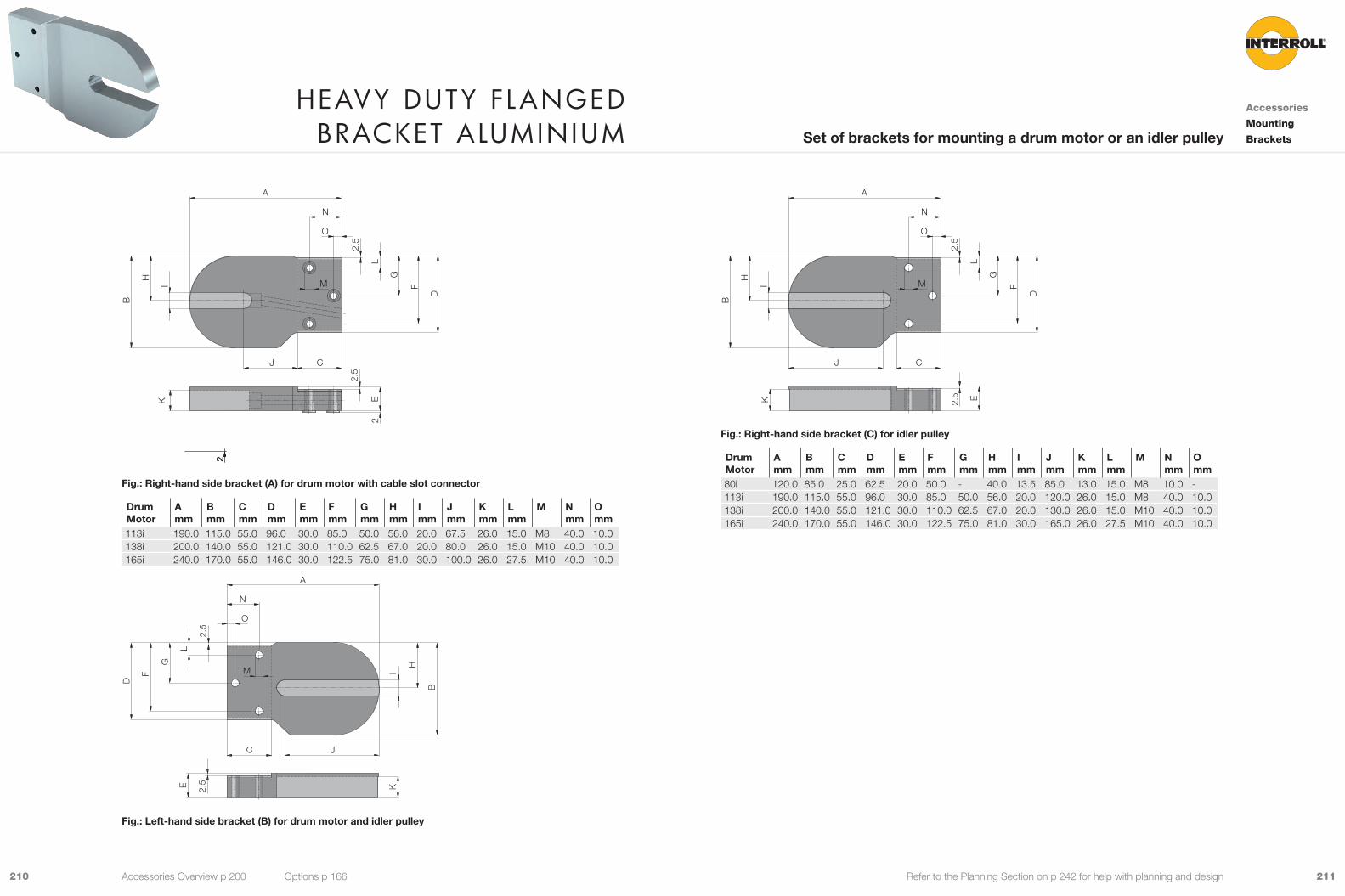
211210 Refer to the Planning Section on p 242 for help with planning and design
2.5
L
G
F
D
O
N
I
H
B
K
J
A
2.5
EC
M
2
222
Fig.: Right-hand side bracket (A) for drum motor with cable slot connector
Drum Motor
A mm
B mm
C mm
D mm
E mm
F mm
G mm
H mm
I mm
J mm
K mm
L mm
M N mm
O mm
113i 190.0 115.0 55.0 96.0 30.0 85.0 50.0 56.0 20.0 67.5 26.0 15.0 M8 40.0 10.0138i 200.0 140.0 55.0 121.0 30.0 110.0 62.5 67.0 20.0 80.0 26.0 15.0 M10 40.0 10.0165i 240.0 170.0 55.0 146.0 30.0 122.5 75.0 81.0 30.0 100.0 26.0 27.5 M10 40.0 10.0
2.5
L
G
F
D
O
N
I
H
B
K
J
A
2.5E
C
M
Fig.: Left-hand side bracket (B) for drum motor and idler pulley
heavy Duty flanGeD braCket alumInIum
Accessories
Mounting
BracketsSet of brackets for mounting a drum motor or an idler pulley
Accessories Overview p 200 Options p 166
2.5
L
G
F
D
O
N
I
H
B
K
J
A
2.5 E
C
M
Fig.: Right-hand side bracket (C) for idler pulley
Drum Motor
A mm
B mm
C mm
D mm
E mm
F mm
G mm
H mm
I mm
J mm
K mm
L mm
M N mm
O mm
80i 120.0 85.0 25.0 62.5 20.0 50.0 - 40.0 13.5 85.0 13.0 15.0 M8 10.0 -113i 190.0 115.0 55.0 96.0 30.0 85.0 50.0 56.0 20.0 120.0 26.0 15.0 M8 40.0 10.0138i 200.0 140.0 55.0 121.0 30.0 110.0 62.5 67.0 20.0 130.0 26.0 15.0 M10 40.0 10.0165i 240.0 170.0 55.0 146.0 30.0 122.5 75.0 81.0 30.0 165.0 26.0 27.5 M10 40.0 10.0

213212 Refer to the Planning Section on p 242 for help with planning and design
Dimensions
2.5
L
G
F
D
O
N
I
H
B
K
J
A
2.5 E
C
M
Fig.: Right-hand side bracket (A) for drum motor with elbow connector straight connector or terminal box
Drum Motor
A mm
B mm
C mm
D mm
E mm
F mm
G mm
H mm
I mm
J mm
K mm
L mm
M N mm
O mm
80i 120.0 85.0 25.0 62.5 20.0 50.0 - 40.0 13.5 47.5 9.0 15.0 M8 10.0 -113i 190.0 115.0 55.0 96.0 30.0 85.0 50.0 56.0 20.0 67.5 20.0 15.0 M8 40.0 10.0138i 200.0 140.0 55.0 121.0 30.0 110.0 62.5 67.0 20.0 80.0 20.0 15.0 M10 40.0 10.0
Product Description 9 For drum motors 80i 113i 138i 165i and correspon-
ding idler pulleys
9 For drum motors with cable connectors or terminal
box
9 Only for drum motors with a threaded hole in the
front shaft (non cable / terminal box side)
9 Only for idler pulleys with a threaded hole in each
shaft end
Note: For threaded shaft dimensions refer to the dimensional drawings for the respective drum motor.
Brackets must be mounted in the following way:
B
C
B
A
Product RangeOne set of brackets comprises of one left-hand bracket and one right-hand bracket.
Drum Motor
Idler Pulley Bracket set Material Electrical con-nector
Art. No.
113i A + B PE Elbow connectorStraight connectorTerminal box
61006805
113i A + B PE Cable slot connector 61008697138i A + B PE Elbow connector
Straight connectorTerminal box
61008702
138i A + B PE Cable slot connector 6110057080i A + B PE Elbow connector
Straight connectorTerminal box
61008693
80i B + C PE 61008695113i B + C PE 61008700138i B + C PE 61008705
Application
Mounting
Overview
heavy Duty flanGeD braCket pe
Accessories
Mounting
BracketsSet of brackets for mounting a drum motor or an idler pulley
Accessories Overview p 200 Options p 166

215214 Refer to the Planning Section on p 242 for help with planning and design
2.5
L
G
F
D
O
N
I
H
B
K
J
A
2.5
EC
M
2
222
Fig.: Right-hand side bracket (A) for drum motor with cable slot connector
Drum Motor
A mm
B mm
C mm
D mm
E mm
F mm
G mm
H mm
I mm
J mm
K mm
L mm
M N mm
O mm
113i 190.0 115.0 55.0 96.0 30.0 85.0 50.0 56.0 20.0 67.5 26.0 15.0 M8 40.0 10.0138i 200.0 140.0 55.0 121.0 30.0 110.0 62.5 67.0 20.0 65.0 26.0 15.0 M10 40.0 10.0
2.5
L
G
F
D
O
N
I
H
B
K
JP
A
2.5E
C
M
2
Fig.: Left-hand side bracket (B) for drum motor and idler pulley
2,5
L
G
F
D
O
N
I
H
B
K
JP
A
2,5 E
C
M
Fig.: Right-hand side bracket (C) for idler pulley
Drum Motor/ Idler Pulley
A mm
B mm
C mm
D mm
E mm
F mm
G mm
H mm
I mm
J mm
K mm
L mm
M N mm
O mm
P mm
80i 120.0 85.0 25.0 62.5 20.0 50.0 - 40.0 13.5 42.5 9.0 15.0 M8 10.0 - 12.5113i 190.0 115.0 55.0 96.0 30.0 85.0 50.0 56.0 20.0 60.0 20.0 15.0 M8 40.0 10.0 17.5138i 200.0 140.0 55.0 121.0 30.0 110.0 62.5 67.0 20.0 60.0 20.0 15.0 M10 40.0 10.0 15.0
heavy Duty flanGeD braCket pe
Accessories
Mounting
BracketsSet of brackets for mounting a drum motor or an idler pulley
Accessories Overview p 200 Options p 166
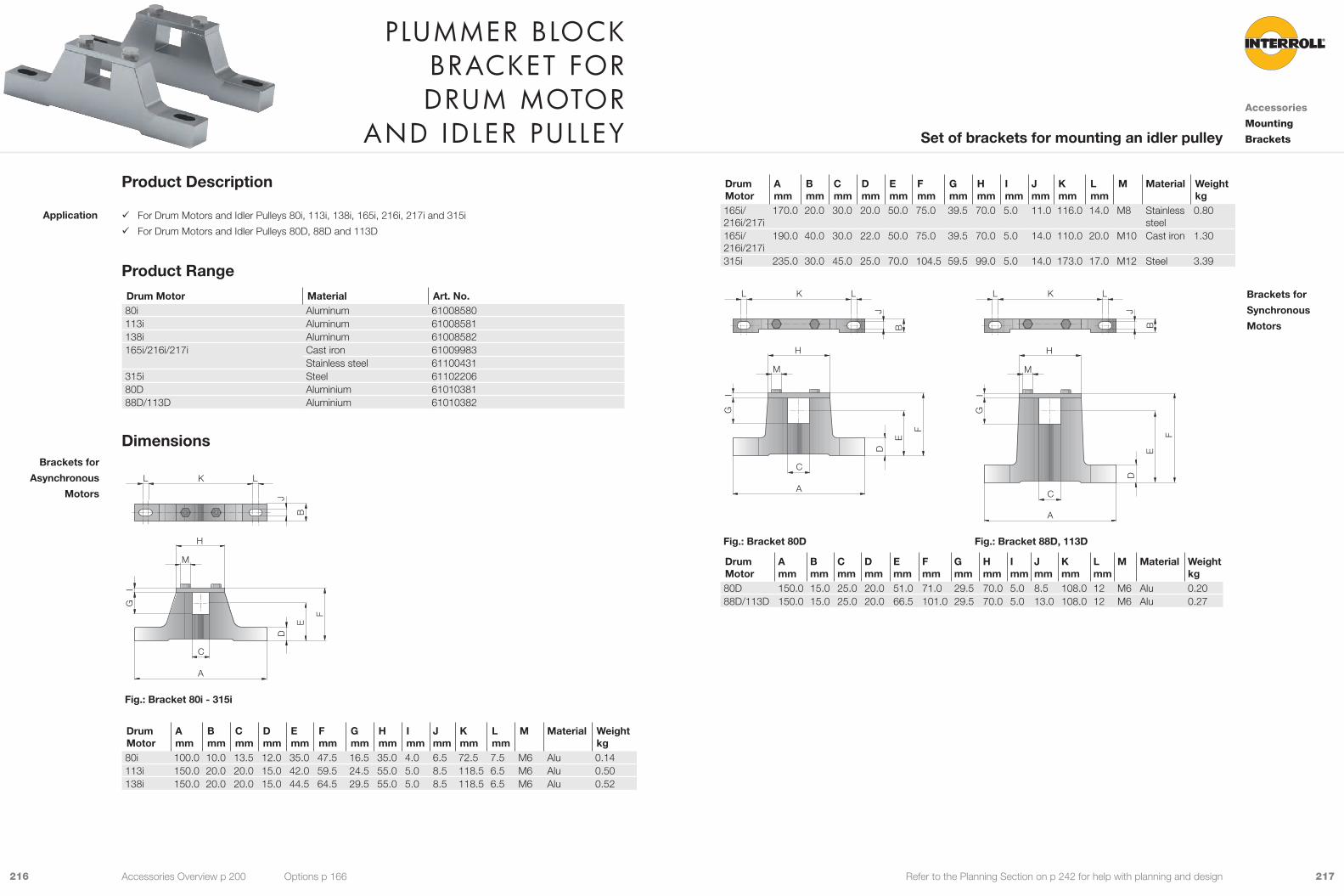
217216 Refer to the Planning Section on p 242 for help with planning and design
Drum Motor
A mm
B mm
C mm
D mm
E mm
F mm
Gmm
H mm
I mm
J mm
K mm
Lmm
M Material Weightkg
165i/ 216i/217i
170.0 20.0 30.0 20.0 50.0 75.0 39.5 70.0 5.0 11.0 116.0 14.0 M8 Stainless steel
0.80
165i/ 216i/217i
190.0 40.0 30.0 22.0 50.0 75.0 39.5 70.0 5.0 14.0 110.0 20.0 M10 Cast iron 1.30
315i 235.0 30.0 45.0 25.0 70.0 104.5 59.5 99.0 5.0 14.0 173.0 17.0 M12 Steel 3.39
I
H
A
C
G
M
E
F
D
K LL
J
B
I
H
A
C
G
M
E
F
D
K LL
J
B
Fig.: Bracket 80D Fig.: Bracket 88D, 113D
Drum Motor
A mm
B mm
C mm
D mm
E mm
F mm
Gmm
H mm
I mm
J mm
K mm
Lmm
M Material Weightkg
80D 150.0 15.0 25.0 20.0 51.0 71.0 29.5 70.0 5.0 8.5 108.0 12 M6 Alu 0.2088D/113D 150.0 15.0 25.0 20.0 66.5 101.0 29.5 70.0 5.0 13.0 108.0 12 M6 Alu 0.27
Brackets for
Synchronous
Motors
Product Description
9 For Drum Motors and Idler Pulleys 80i, 113i, 138i, 165i, 216i, 217i and 315i
9 For Drum Motors and Idler Pulleys 80D, 88D and 113D
Product RangeDrum Motor Material Art. No.80i Aluminum 61008580113i Aluminum 61008581138i Aluminum 61008582165i/216i/217i Cast iron 61009983
Stainless steel 61100431315i Steel 6110220680D Aluminium 6101038188D/113D Aluminium 61010382
Dimensions
I
H
E
F
A
D
C
G
K LL
B
J
M
Fig.: Bracket 80i - 315i
Drum Motor
A mm
B mm
C mm
D mm
E mm
F mm
Gmm
H mm
I mm
J mm
K mm
Lmm
M Material Weightkg
80i 100.0 10.0 13.5 12.0 35.0 47.5 16.5 35.0 4.0 6.5 72.5 7.5 M6 Alu 0.14113i 150.0 20.0 20.0 15.0 42.0 59.5 24.5 55.0 5.0 8.5 118.5 6.5 M6 Alu 0.50138i 150.0 20.0 20.0 15.0 44.5 64.5 29.5 55.0 5.0 8.5 118.5 6.5 M6 Alu 0.52
Application
Brackets for
Asynchronous
Motors
plummer bloCk braCket for Drum motor
anD IDler pulleyAccessories
Mounting
BracketsSet of brackets for mounting an idler pulley
Accessories Overview p 200 Options p 166
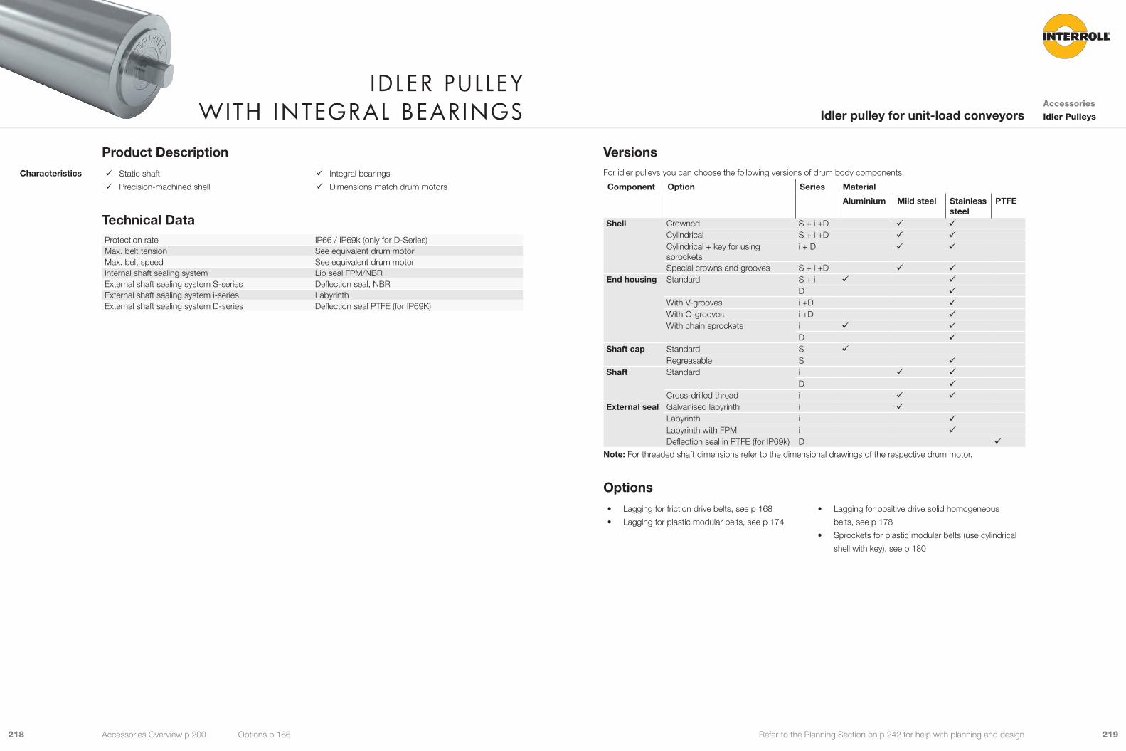
219218 Refer to the Planning Section on p 242 for help with planning and design
VersionsFor idler pulleys you can choose the following versions of drum body components:
Component Option Series Material
Aluminium Mild steel Stainless steel
PTFE
Shell Crowned S + i +D 9 9Cylindrical S + i +D 9 9Cylindrical + key for using sprockets
i + D 9 9
Special crowns and grooves S + i +D 9 9End housing Standard S + i 9 9
D 9With V-grooves i +D 9With O-grooves i +D 9With chain sprockets i 9 9
D 9Shaft cap Standard S 9
Regreasable S 9Shaft Standard i 9 9
D 9Cross-drilled thread i 9 9
External seal Galvanised labyrinth i 9Labyrinth i 9Labyrinth with FPM i 9Deflection seal in PTFE (for IP69k) D 9
Note: For threaded shaft dimensions refer to the dimensional drawings of the respective drum motor.
Options• Lagging for friction drive belts, see p 168
• Lagging for plastic modular belts, see p 174
• Lagging for positive drive solid homogeneous
belts, see p 178
• Sprockets for plastic modular belts (use cylindrical
shell with key), see p 180
Product Description 9 Static shaft
9 Precision-machined shell
9 Integral bearings
9 Dimensions match drum motors
Technical DataProtection rate IP66 / IP69k (only for D-Series)Max. belt tension See equivalent drum motorMax. belt speed See equivalent drum motorInternal shaft sealing system Lip seal FPM/NBRExternal shaft sealing system S-series Deflection seal, NBRExternal shaft sealing system i-series LabyrinthExternal shaft sealing system D-series Deflection seal PTFE (for IP69K)
Characteristics
ID ler pulley WIth InteGral bearInGs Accessories
Idler PulleysIdler pulley for unit-load conveyors
Accessories Overview p 200 Options p 166

221220 Refer to the Planning Section on p 242 for help with planning and design
H
G G
CC
H
1/3 1/3 1/3
F
EL
FW
AGL
SL
ØA
ØB
ØD
Fig.: Idler D-Series (80D, 113D)
G E
CC
G
F
EL
FW
AGL
SL
ØA
ØD
B
Fig.: Idler D-Series (88D)
Idler pulley, crowned shell Ø Amm
Ø Bmm
Cmm
Ø Dmm
Ø Emm
Fmm
Gmm
Hmm
80S with SL 260 mm to 602 mm 81.5 80 20 35 45 21 5 880S with SL 652 mm to 952 mm 83 81 20 35 45 21 5 880i 81.5 80.5 12.5 17 43 13.5 3.5 6113S 113.3 112.3 20 35 45 21 11 14113i 113.5 112 25 25 83 20 20 10138i 138 136 25 30 100 20 6.5 15165i 164 162 45 40 130 30 8.5 20216i/217i 217.5 215.5 45 40 120 30 8.5 20315i 320 317 45 60 120 45 15 2080D 81.5 80.5 12.5 30 25 3.5 688D 80.5 88 12.5 30 90 25 6 6113D 113.5 112 12.5 30 25 3.5 6
Dimensions
ØB
ØA
ØE
FW
ELC C
ØD
F
HH
GG
SL
AGL
1/3 1/3 1/3
Fig.: Idler i-series
F
EL
AGL
ØE
ØA
SL
FW
ØB ØD
1/3 1/3 1/3
H
C C
G
H
G
Fig.: Idler S-series
ID ler pulley WIth InteGral bearInGs Accessories
Idler PulleysIdler pulley for unit-load conveyors
Accessories Overview p 200 Options p 166

223222 Refer to the Planning Section on p 242 for help with planning and design
The idler pulleys weight depend on its length.
80SShell length SL in mm 260 270 285 302 352 402 452 502 552 602 652 702 752Average weight in kg 2.2 2.3 2.4 2.5 2.85 3.2 3.55 3.9 4.25 4.6 7.0 7.5 8.0Shell length SL in mm 802 852 902 952Average weight in kg 8.5 9.0 9.5 10.0
80iShell length SL in mm 193 243 293 343 393 443 493 543Average weight in kg 1.8 2.1 2.4 2.7 3.0 3.3 3.6 3.9
113SShell length SL in mm 240 290 340 390 440 490 540 590 640 690 740 790 840Average weight in kg 3 3.4 3.8 4.2 4.6 5.0 5.4 5.8 6.2 6.6 7.0 7.4 7.8Shell length SL in mm 890 940 990 1,040 1,090Average weight in kg 8.2 8.6 9.0 9.4 9.8
113iShell length SL in mm 250 300 350 400 450 500 550 600 650 700 750 800 850Average weight in kg 3.5 4.0 4.5 5.0 5.5 6.0 6.5 7.0 7.5 8.0 8.5 9.0 9.5
138iShell length SL in mm 300 350 400 450 500 550 600 650 700 750 800 850 900Average weight in kg 6.5 7.0 7.5 8.0 8.5 9.0 9.5 10.0 10.5 11.0 11.5 12.0 12.5
165iShell length SL in mm 400 450 500 550 600 650 700 750 800 850 900 950 1,000Average weight in kg 14 15.5 17.0 18.5 20.0 21.5 23.0 24.5 26.0 27.5 29.0 30.5 32.0
216i/217iShell length SL in mm 400 450 500 550 600 650 700 750 800 850 900 950 1,000Average weight in kg 19 21 23 25 27 29 31 33 35 37 39 41 43
Standard length
and weight
ID ler pulley WIth InteGral bearInGs Accessories
Idler PulleysIdler pulley for unit-load conveyors
Accessories Overview p 200 Options p 166
80DShell length SL in mm 200 250 300 350 400 450 500 550 600 650 700 750 800 850 900Average weight in kg 3.5 4.0 4.4 4.9 5.3 5.8 6.2 6.7 7.1 7.6 8.0 8.5 8.9 9.4 9.8
88DShell length SL in mm 200 250 300 350 400 450 500 550 600 650 700 750 800 850 900Average weight in kg 5.1 5.6 6.2 6.7 7.2 7.7 8.2 8.8 9.3 9.8 10.3 10.8 11.3 11.9 12.4
113DShell length SL in mm 200 250 300 350 400 450 500 550 600 650 700 750 800 850 900Average weight in kg 5.4 6.1 6.9 7.6 8.3 9.0 9.7 10.5 11.2 12.0 12.6 13.3 14.0 14.8 15.5
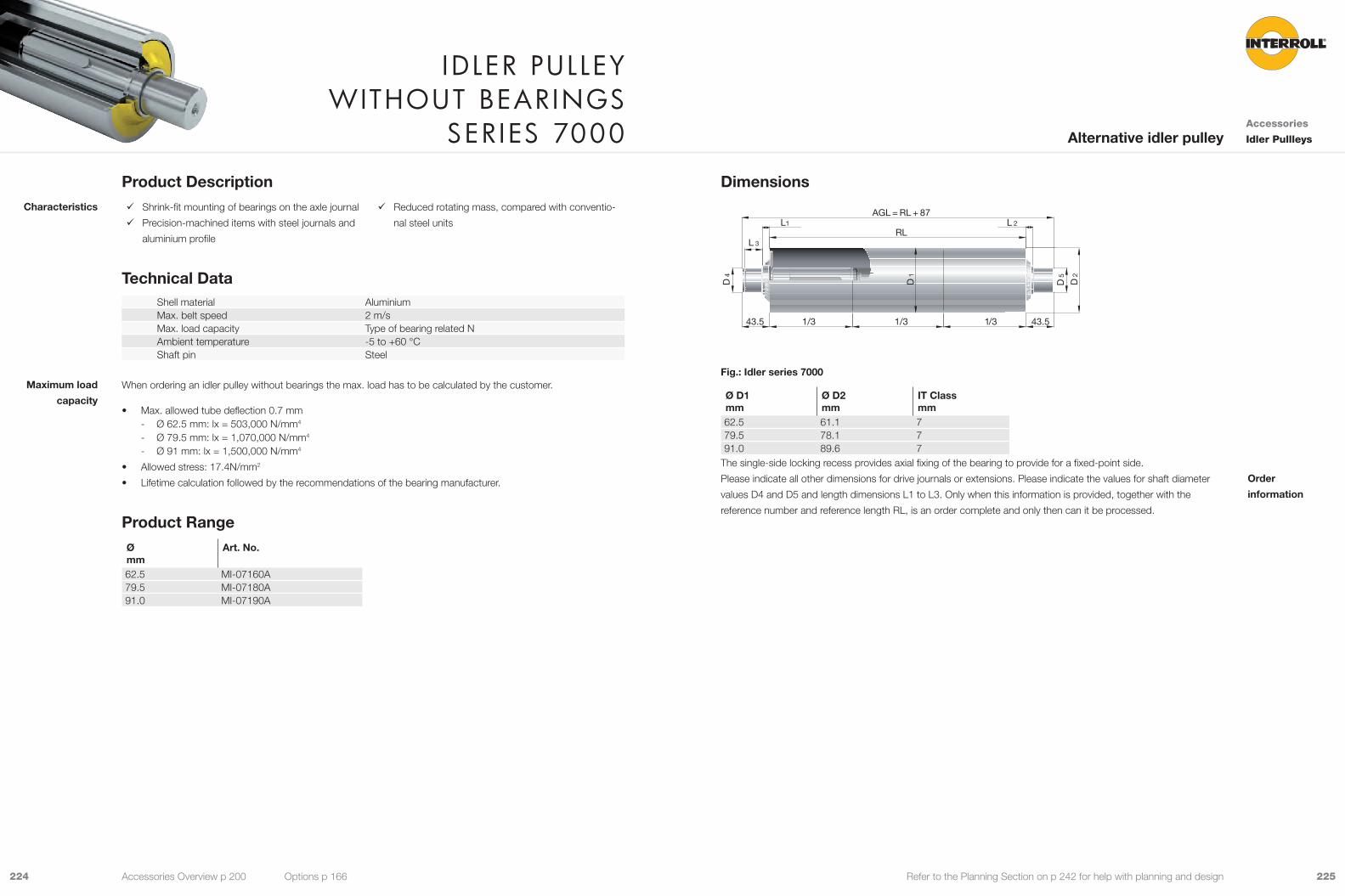
225224 Refer to the Planning Section on p 242 for help with planning and design
Dimensions
1/3 1/3 1/3 43.543.5
RL
AGL = RL + 87L1 L 2
L 3
D 1
D 2
D 4
D 5
Fig.: Idler series 7000
Ø D1mm
Ø D2mm
IT Classmm
62.5 61.1 779.5 78.1 791.0 89.6 7
The single-side locking recess provides axial fixing of the bearing to provide for a fixed-point side.
Please indicate all other dimensions for drive journals or extensions. Please indicate the values for shaft diameter
values D4 and D5 and length dimensions L1 to L3. Only when this information is provided, together with the
reference number and reference length RL, is an order complete and only then can it be processed.
Order
information
Product Description 9 Shrink-fit mounting of bearings on the axle journal
9 Precision-machined items with steel journals and
aluminium profile
9 Reduced rotating mass, compared with conventio-
nal steel units
Technical DataShell material AluminiumMax. belt speed 2 m/sMax. load capacity Type of bearing related NAmbient temperature -5 to +60 °CShaft pin Steel
When ordering an idler pulley without bearings the max. load has to be calculated by the customer.
• Max. allowed tube deflection 0.7 mm - Ø 62.5 mm: lx = 503,000 N/mm4
- Ø 79.5 mm: lx = 1,070,000 N/mm4
- Ø 91 mm: lx = 1,500,000 N/mm4
• Allowed stress: 17.4N/mm2
• Lifetime calculation followed by the recommendations of the bearing manufacturer.
Product RangeØmm
Art. No.
62.5 MI-07160A79.5 MI-07180A91.0 MI-07190A
Characteristics
Maximum load
capacity
ID ler pulley WIthout bearInGs
serIes 7000 Accessories
Idler PullleysAlternative idler pulley
Accessories Overview p 200 Options p 166

227226 Refer to the Planning Section on p 242 for help with planning and design
The maximum static load resulting from preset belt tensioning is as follows:
• Ø 62.5 mm = 6,000 N
• Ø 79.5 mm = 8,000 N
• Ø 91.0 mm = 8,000 N
Product RangeØmm
Art. No.
62.5 MI-07160B79.5 MI-07180B91.0 MI-07190B
Dimensions
X 1
X 2
M 2
1/3 1/3 1/3 5050
RLEL = RL + 106
D 1
D 3
D 2
Fig.: Idler series 7000
Ø D1mm
Ø D2mm
Ø D3 Bearing housingmm
X1 / X2mm
M2
62.5 61.1 59.0 23.0 M879.5 78.1 75.0 29.0 M1091.0 89.6 88.6 35.0 M10
Product Description 9 Standard interface with bearing housings provided
with inside thread for attachment to belt section
profile or to tensioning stations
9 Shrink-fit mounting of bearings on the axle journal
9 Precision-machined items with steel journals and
aluminium profile
9 Reduced rotating mass, compared with conventio-
nal steel units
9 Allowed stress 17.4 N/mm²
Technical DataShell material AluminiumMax. belt speed 2 m/sMax. load capacity 4,300 NAmbient temperature -5 to +60 °CShaft pin SteelBall bearing Steel, 2205 2RS / Steel, 2206 2RSBearing housing Steel, burnished
Ø 62.5 mm
RL
Rpm
150 200 250 300 350 400 450
in m/s
0.50 0.66 0.82 1.00 1.15 1.32 1.50300 4,000 3,700 3,400 3,200 3,000 2,900 2,800500 3,800 3,400 3,100 2,900 2,800 2,600 2,500700 3,000 2,600 2,300 2,100 2,000 1,800 1,7001,000 2,400 2,000 1,700 1,500 1,400 1,200 1,100
Ø 79.5 mm
RL
Rpm
150 200 250 300 350 400 450
in m/s
0.50 0.66 0.82 1.00 1.15 1.32 1.50300 4,300 3,900 3,650 3,450 3,250 3,100 3,000500 3,950 3,550 3,300 3,100 2,900 2,750 2,650700 3,500 3,100 2,850 2,600 2,450 2,300 2,2001,000 3,150 2,750 2,500 2,250 2,100 1,950 1,850
Ø 91.0 mm
RL
Rpm
150 200 250 300 350 400
in m/s
0.50 0.66 0.82 1.00 1.15 1.32300 4,300 3,900 3,650 3,450 3,250 3,100500 4,200 3,800 3,550 3,300 3,150 3,000700 4,100 3,700 3,450 3,200 3,050 2,9001,000 3,950 3,550 3,300 3,050 2,900 2,750
Characteristics
Max. dynamic
load capacity
in N
ID ler pulley WIth bearInGs
serIes 7000 Accessories
Idler PullleysAlternative idler pulley
Accessories Overview p 200 Options p 166
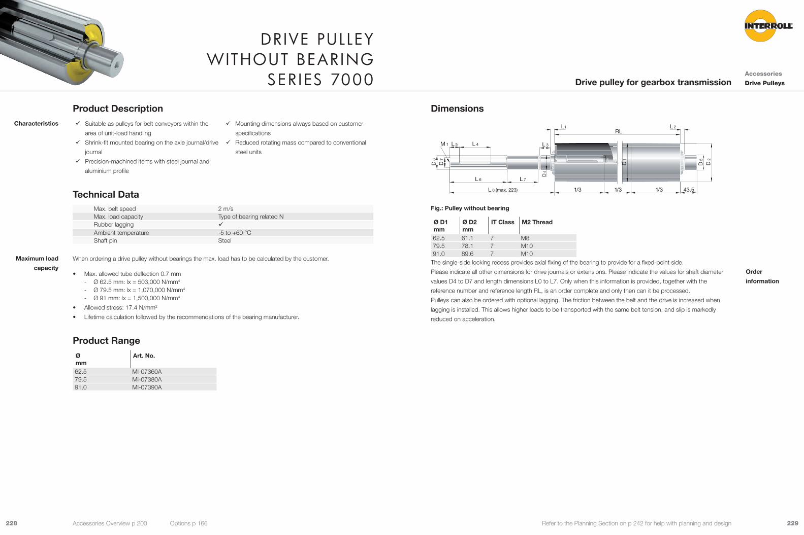
229228 Refer to the Planning Section on p 242 for help with planning and design
Dimensions
1/3 1/3 1/3 43.5
RLL1 L 2
L 3
D 1
D 2
D 4
D 5
D 6
L 7L 6
L 0 (max. 223)
L 5 L 4M 1
D 7
Fig.: Pulley without bearing
Ø D1mm
Ø D2mm
IT Class M2 Thread
62.5 61.1 7 M879.5 78.1 7 M1091.0 89.6 7 M10
The single-side locking recess provides axial fixing of the bearing to provide for a fixed-point side.
Please indicate all other dimensions for drive journals or extensions. Please indicate the values for shaft diameter
values D4 to D7 and length dimensions L0 to L7. Only when this information is provided, together with the
reference number and reference length RL, is an order complete and only then can it be processed.
Pulleys can also be ordered with optional lagging. The friction between the belt and the drive is increased when
lagging is installed. This allows higher loads to be transported with the same belt tension, and slip is markedly
reduced on acceleration.
Order
information
Product Description 9 Suitable as pulleys for belt conveyors within the
area of unit-load handling
9 Shrink-fit mounted bearing on the axle journal/drive
journal
9 Precision-machined items with steel journal and
aluminium profile
9 Mounting dimensions always based on customer
specifications
9 Reduced rotating mass compared to conventional
steel units
Technical DataMax. belt speed 2 m/sMax. load capacity Type of bearing related NRubber lagging 9Ambient temperature -5 to +60 °CShaft pin Steel
When ordering a drive pulley without bearings the max. load has to be calculated by the customer.
• Max. allowed tube deflection 0.7 mm - Ø 62.5 mm: lx = 503,000 N/mm4
- Ø 79.5 mm: lx = 1,070,000 N/mm4
- Ø 91 mm: lx = 1,500,000 N/mm4
• Allowed stress: 17.4 N/mm2
• Lifetime calculation followed by the recommendations of the bearing manufacturer.
Product RangeØmm
Art. No.
62.5 MI-07360A79.5 MI-07380A91.0 MI-07390A
Characteristics
Maximum load
capacity
DrIve pulley WIthout bearInG
serIes 7000 Accessories
Drive PulleysDrive pulley for gearbox transmission
Accessories Overview p 200 Options p 166
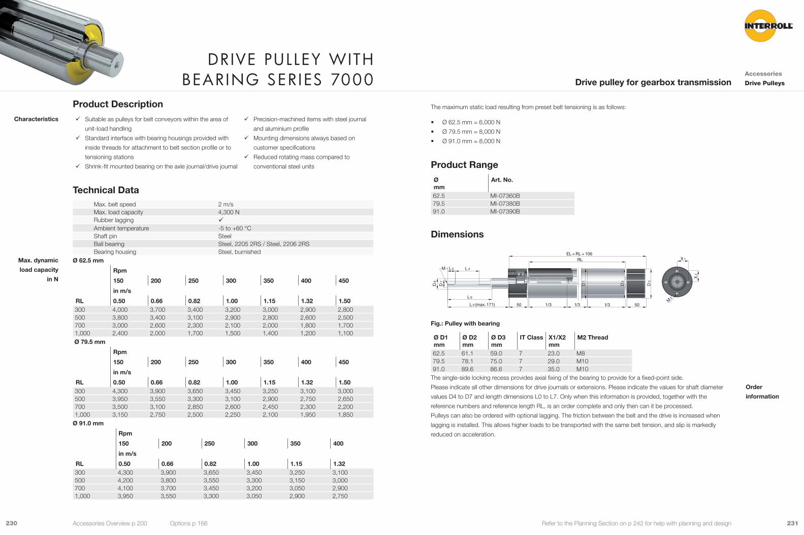
231230 Refer to the Planning Section on p 242 for help with planning and design
The maximum static load resulting from preset belt tensioning is as follows:
• Ø 62.5 mm = 6,000 N
• Ø 79.5 mm = 8,000 N
• Ø 91.0 mm = 8,000 N
Product RangeØmm
Art. No.
62.5 MI-07360B79.5 MI-07380B91.0 MI-07390B
Dimensions
1/3 1/3 1/3 5050
RLEL = RL + 106
D 1
D 3
D 2
D 6
L 6
L 0 (max. 171)
L 5 L 4M 1
D 7
X 1
X 2
M 2
Fig.: Pulley with bearing
Ø D1mm
Ø D2mm
Ø D3mm
IT Class X1/X2mm
M2 Thread
62.5 61.1 59.0 7 23.0 M879.5 78.1 75.0 7 29.0 M1091.0 89.6 86.6 7 35.0 M10
The single-side locking recess provides axial fixing of the bearing to provide for a fixed-point side.
Please indicate all other dimensions for drive journals or extensions. Please indicate the values for shaft diameter
values D4 to D7 and length dimensions L0 to L7. Only when this information is provided, together with the
reference numbers and reference length RL, is an order complete and only then can it be processed.
Pulleys can also be ordered with optional lagging. The friction between the belt and the drive is increased when
lagging is installed. This allows higher loads to be transported with the same belt tension, and slip is markedly
reduced on acceleration.
Order
information
Product Description 9 Suitable as pulleys for belt conveyors within the area of
unit-load handling
9 Standard interface with bearing housings provided with
inside threads for attachment to belt section profile or to
tensioning stations
9 Shrink-fit mounted bearing on the axle journal/drive journal
9 Precision-machined items with steel journal
and aluminium profile
9 Mounting dimensions always based on
customer specifications
9 Reduced rotating mass compared to
conventional steel units
Technical DataMax. belt speed 2 m/sMax. load capacity 4,300 NRubber lagging 9Ambient temperature -5 to +60 °CShaft pin SteelBall bearing Steel, 2205 2RS / Steel, 2206 2RSBearing housing Steel, burnished
Ø 62.5 mm
RL
Rpm
150 200 250 300 350 400 450
in m/s
0.50 0.66 0.82 1.00 1.15 1.32 1.50300 4,000 3,700 3,400 3,200 3,000 2,900 2,800500 3,800 3,400 3,100 2,900 2,800 2,600 2,500700 3,000 2,600 2,300 2,100 2,000 1,800 1,7001,000 2,400 2,000 1,700 1,500 1,400 1,200 1,100
Ø 79.5 mm
RL
Rpm
150 200 250 300 350 400 450
in m/s
0.50 0.66 0.82 1.00 1.15 1.32 1.50300 4,300 3,900 3,650 3,450 3,250 3,100 3,000500 3,950 3,550 3,300 3,100 2,900 2,750 2,650700 3,500 3,100 2,850 2,600 2,450 2,300 2,2001,000 3,150 2,750 2,500 2,250 2,100 1,950 1,850
Ø 91.0 mm
RL
Rpm
150 200 250 300 350 400
in m/s
0.50 0.66 0.82 1.00 1.15 1.32300 4,300 3,900 3,650 3,450 3,250 3,100500 4,200 3,800 3,550 3,300 3,150 3,000700 4,100 3,700 3,450 3,200 3,050 2,9001,000 3,950 3,550 3,300 3,050 2,900 2,750
Characteristics
Max. dynamic
load capacity
in N
DrIve pulley WIth bearInG serIes 7000 Accessories
Drive PulleysDrive pulley for gearbox transmission
Accessories Overview p 200 Options p 166
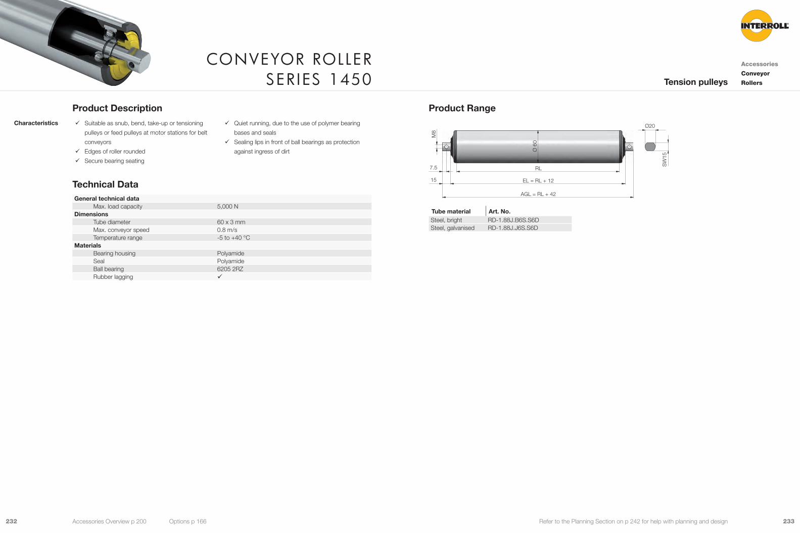
233232 Refer to the Planning Section on p 242 for help with planning and design
Product Range
7.5
15
RL
AGL = RL + 42
Ø 6
0
M8
SW
15
EL = RL + 12
Ø20
Tube material Art. No.Steel, bright RD-1.88J.B6S.S6DSteel, galvanised RD-1.88J.J6S.S6D
Product Description 9 Suitable as snub, bend, take-up or tensioning
pulleys or feed pulleys at motor stations for belt
conveyors
9 Edges of roller rounded
9 Secure bearing seating
9 Quiet running, due to the use of polymer bearing
bases and seals
9 Sealing lips in front of ball bearings as protection
against ingress of dirt
Technical DataGeneral technical data
Max. load capacity 5,000 NDimensions
Tube diameter 60 x 3 mmMax. conveyor speed 0.8 m/sTemperature range -5 to +40 °C
Materials Bearing housing PolyamideSeal PolyamideBall bearing 6205 2RZRubber lagging 9
Characteristics
Conveyor roller ser Ies 1450
Accessories
Conveyor
RollersTension pulleys
Accessories Overview p 200 Options p 166
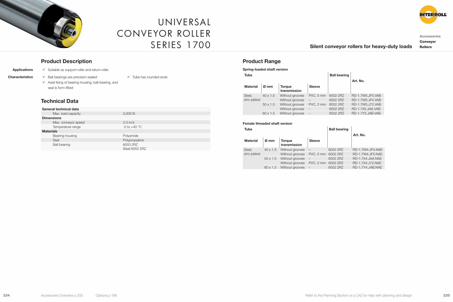
235234 Refer to the Planning Section on p 242 for help with planning and design
Product RangeSpring-loaded shaft version
Tube Ball bearing
Art. No.
Material Ø mm Torque transmission
Sleeve
Steel, zinc-plated
40 x 1.5 Without grooves PVC, 5 mm 6002 2RZ RD-1.7W5.JF5.VABWithout grooves – 6002 2RZ RD-1.7W5.JF4.VAB
50 x 1.5 Without grooves PVC, 2 mm 6002 2RZ RD-1.7W5.J72.VABWithout grooves – 6002 2RZ RD-1.7X5.JAA.VAB
60 x 1.5 Without grooves – 6002 2RZ RD-1.7Y5.JAB.VAB
Female threaded shaft version
Tube Ball bearing
Art. No.
Material Ø mm Torque transmission
Sleeve
Steel, zinc-plated
40 x 1.5 Without grooves – 6002 2RZ RD-1.7W4.JF4.NAEWithout grooves PVC, 5 mm 6002 2RZ RD-1.7W4.JF5.NAE
50 x 1.5 Without grooves – 6002 2RZ RD-1.7X4.JAA.NAEWithout grooves PVC, 2 mm 6002 2RZ RD-1.7X4.J72.NAE
60 x 1.5 Without grooves – 6002 2RZ RD-1.7Y4.JAB.NAE
Product Description 9 Suitable as support roller and return roller
9 Ball bearings are precision sealed
9 Axial fixing of bearing housing, ball bearing, and
seal is form-fitted
9 Tube has rounded ends
Technical DataGeneral technical data
Max. load capacity 3,000 NDimensions
Max. conveyor speed 2.0 m/sTemperature range -5 to +40 °C
Materials Bearing housing PolyamideSeal PolypropyleneBall bearing 6003 2RZ
Steel 6002 2RZ
Applications
Characteristics
unIversal Conveyor roller
ser Ies 1700Accessories
Conveyor
RollersSilent conveyor rollers for heavy-duty loads
Accessories Overview p 200 Options p 166
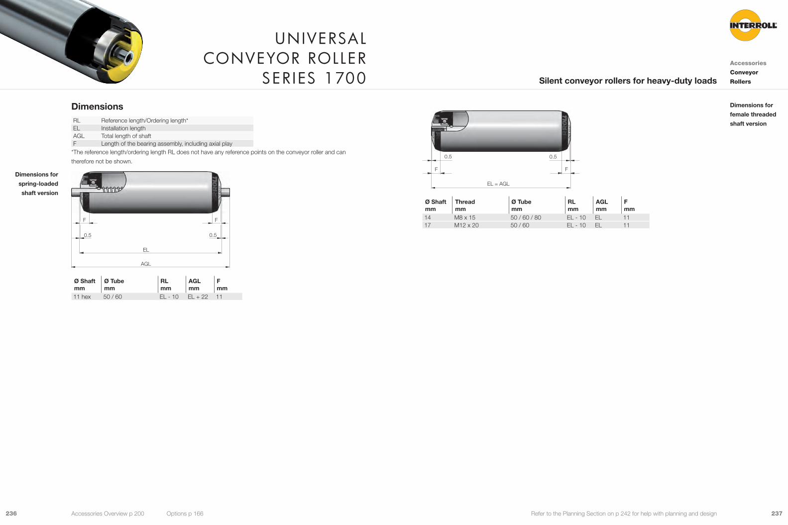
237236 Refer to the Planning Section on p 242 for help with planning and design
0.5 0.5
F F
EL = AGL
Ø Shaftmm
Threadmm
Ø Tubemm
RLmm
AGLmm
Fmm
14 M8 x 15 50 / 60 / 80 EL - 10 EL 1117 M12 x 20 50 / 60 EL - 10 EL 11
Dimensions for
female threaded
shaft version
DimensionsRL Reference length/Ordering length*EL Installation lengthAGL Total length of shaftF Length of the bearing assembly, including axial play
*The reference length/ordering length RL does not have any reference points on the conveyor roller and can
therefore not be shown.
0.5 0.5
F F
EL
AGL
Ø Shaftmm
Ø Tubemm
RLmm
AGLmm
Fmm
11 hex 50 / 60 EL - 10 EL + 22 11
Dimensions for
spring-loaded
shaft version
unIversal Conveyor roller
ser Ies 1700Accessories
Conveyor
RollersSilent conveyor rollers for heavy-duty loads
Accessories Overview p 200 Options p 166
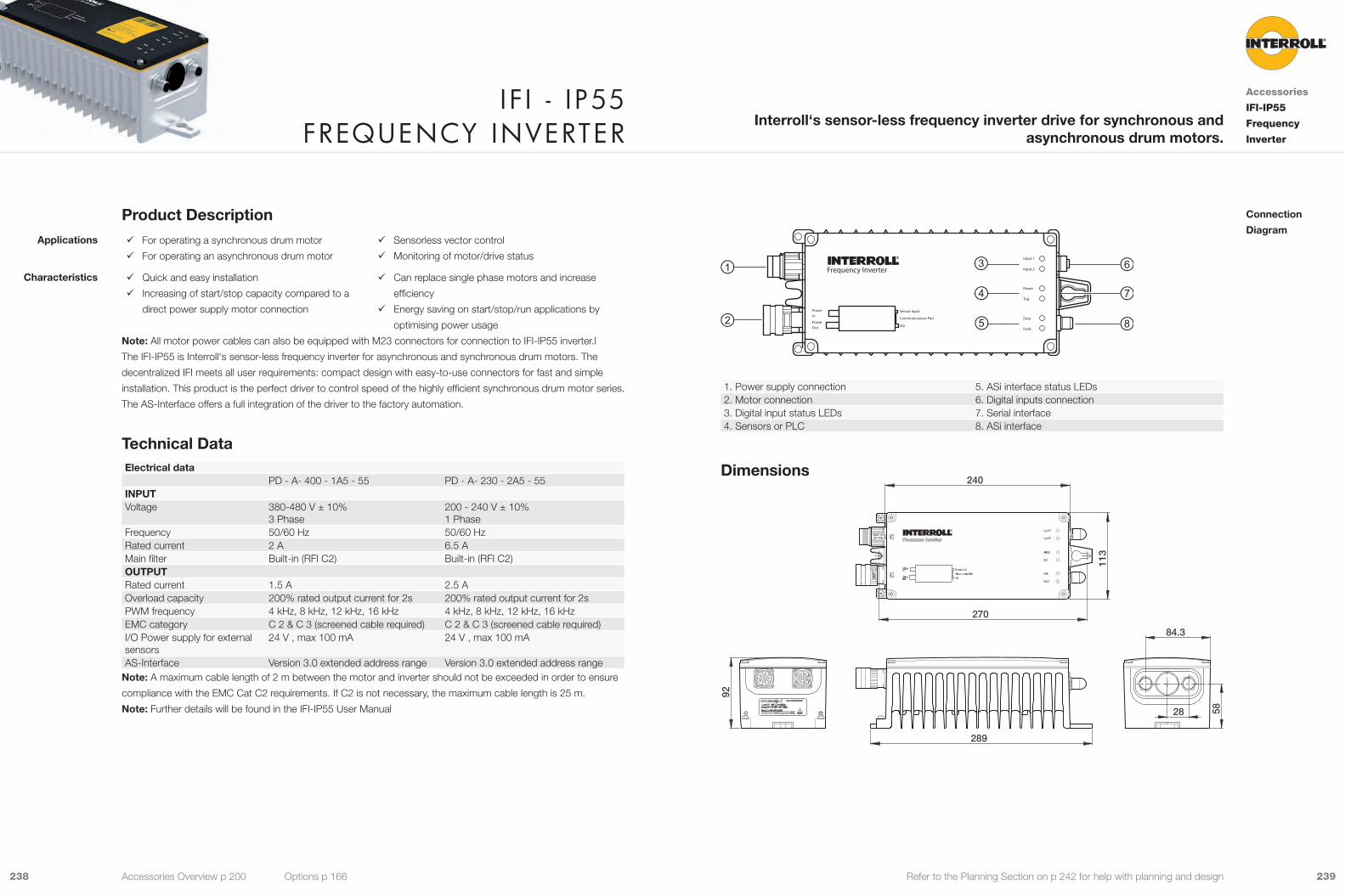
239238 Refer to the Planning Section on p 242 for help with planning and design
Frequency Inverter
PowerIn
PowerOut
Input 1
Input 2
Power
Trip
Data
Fault
Sensor Input
Communications Part
ASI
1. Power supply connection 5. ASi interface status LEDs2. Motor connection 6. Digital inputs connection3. Digital input status LEDs 7. Serial interface4. Sensors or PLC 8. ASi interface
Dimensions
28 58
84.3
289
270
113
240
92
Connection
DiagramProduct Description
9 For operating a synchronous drum motor
9 For operating an asynchronous drum motor
9 Sensorless vector control
9 Monitoring of motor/drive status
9 Quick and easy installation
9 Increasing of start/stop capacity compared to a
direct power supply motor connection
9 Can replace single phase motors and increase
efficiency
9 Energy saving on start/stop/run applications by
optimising power usage
Note: All motor power cables can also be equipped with M23 connectors for connection to IFI-IP55 inverter.l
The IFI-IP55 is Interroll‘s sensor-less frequency inverter for asynchronous and synchronous drum motors. The
decentralized IFI meets all user requirements: compact design with easy-to-use connectors for fast and simple
installation. This product is the perfect driver to control speed of the highly efficient synchronous drum motor series.
The AS-Interface offers a full integration of the driver to the factory automation.
Technical DataElectrical data
PD - A- 400 - 1A5 - 55 PD - A- 230 - 2A5 - 55INPUTVoltage 380-480 V ± 10%
3 Phase200 - 240 V ± 10%1 Phase
Frequency 50/60 Hz 50/60 HzRated current 2 A 6.5 AMain filter Built-in (RFI C2) Built-in (RFI C2)OUTPUTRated current 1.5 A 2.5 AOverload capacity 200% rated output current for 2s 200% rated output current for 2sPWM frequency 4 kHz, 8 kHz, 12 kHz, 16 kHz 4 kHz, 8 kHz, 12 kHz, 16 kHzEMC category C 2 & C 3 (screened cable required) C 2 & C 3 (screened cable required)I/O Power supply for external sensors
24 V , max 100 mA 24 V , max 100 mA
AS-Interface Version 3.0 extended address range Version 3.0 extended address rangeNote: A maximum cable length of 2 m between the motor and inverter should not be exceeded in order to ensure
compliance with the EMC Cat C2 requirements. If C2 is not necessary, the maximum cable length is 25 m.
Note: Further details will be found in the IFI-IP55 User Manual
Applications
Characteristics
I f I - I p55 frequenCy Inverter
Accessories
IFI-IP55
Frequency
Inverter
Interroll‘s sensor-less frequency inverter drive for synchronous and asynchronous drum motors.
Accessories Overview p 200 Options p 166
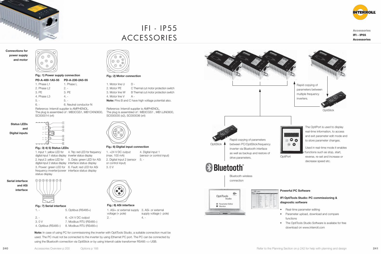
OptiTools
Parameter EditorMonitor
Studio
The OptiPort is used to display
real-time information, to access
and exit parameter edit mode and
to store parameter changes.
Used in real-time mode it enables
functions such as stop, start,
reverse, re-set and increase or
decrease speed etc.
241240 Refer to the Planning Section on p 242 for help with planning and design
Fig.: 1) Power supply connection Fig.: 2) Motor connectionPD-A-400-1A5-55 PD-A-230-2A5-551. Phase L1 1. Phase L 1. Motor line U D -2. Phase L2 2. - 2. Motor PE C Thermal cut motor protection switch3. PE 3. PE 3. Motor line W B Thermal cut motor protection switch4. Phase L3 4. - 4. Motor line V A -5. - 5. - Note: Pins B and C have high voltage potential also.6. - 6. Neutral conductor NReference: Interroll supplier is AMPHENOL.The plug is assembled of : MB3CGS1, MB1CKN0600, SC000014 (x4)
Reference: Interroll supplier is AMPHENOL.The plug is assembled of : MB3CGS1 , MB1JJN0800, SC000035 (x2), SC000036 (x4)
Input 1
Input 2
Power
Trip
Data
Fault
Fig.: 3) 4) 5) Status LEDs Fig.: 6) Digital input connection
1. Input 1: yellow LED for digital input 1 status display
4. Trip: red LED for frequency inverter status display
1. +24 V DC output (max. 100 mA)
4. Digital input 1 (sensor or control input)
2. Input 2: yellow LED for digital input 2 status display
5. Data: green LED for ASi interface status display
2. Digital input 2 (sensor or control input)
5. -
3. Power: green LED for frequency inverter/power status display
6. Fault: red LED for ASi interface status display
3. 0 V
Fig.: 7) Serial interface Fig.: 8) ASi interface
1. - 5. Optibus (RS485+) 1. ASi+ or external supply voltage (+ pole)
3. ASi- or external supply voltage (- pole)
2. - 6. +24 V DC output 2. - 4. -3. 0 V 7. Modbus RTU (RS485–)4. Optibus (RS485–) 8. Modbus RTU (RS485+)
Note: In case of using PC for commissioning the inverter with OptiTools Studio, a suitable connection must be
used. The PC must not be connected to the inverter by using Ethernet PC port. The PC can be connected by
using the Bluetooth connection via OptiStick or by using Interroll cable transformer RS485 <> USB.
Connections for
power supply
and motor
Status LEDs
and
Digital inputs
Serial interface
and ASi
interface
I f I - I p55 aCCessorIes
Accessories
IFI - IP55
Accessories
Rapid copying of
parameters between
multiple frequency
inverters.
OptiStick
OptiPort
Rapid copying of parameters
between PC/OptiStick/frequency
inverter via Bluetooth interface
as well as backup and restore of
drive parameters.
Bluetooth wireless
connection
Powerful PC Software
IFI OptiTools Studio: PC commissioning &
diagnostic software
• Real-time parameter editing
• Parameter upload, download and compare
functions
• The OptiTools Studio Software is availabe for free
download on www.interroll.com
OptiStick
Accessories Overview p 200 Options p 166
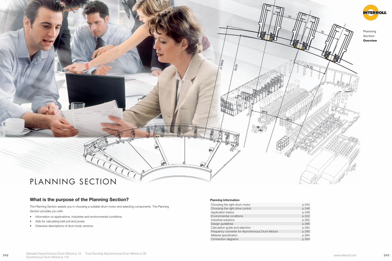
243242 www.interroll.com
Planning Section
What is the purpose of the Planning Section? The Planning Section assists you in choosing a suitable drum motor and selecting components. The Planning
Section provides you with:
• Information on applications, industries and environmental conditions
• Aids for calculating belt pull and power
• Extensive descriptions of drum body versions
Planning
Section
Overview
Standard Asynchronous Drum Motors p 12 Cool-Running Asynchronous Drum Motors p 90 Synchronous Drum Motors p 140
Planning Information
Choosing the right drum motor p 244Choosing the right drive control p 246Application basics p 248Environmental conditions p 252Industrial solutions p 262Design guidelines p 266Calculation guide and selection p 284Frequency converter for Asynchronous Drum Motors p 290Material specification p 294Connection diagrams p 304

245244 www.interroll.com
Choose Options and Accessories
T1
T2
TE
Friction Drive Belt Application
Positive Drive Belt or Non-Belt Application
Choose Options and Accessories
ChooseCool-RunningDrum Motor
ChooseStandard
Drum Motor
Choose Options and Accessories
Choose Options and Accessories
ChooseStandard
Drum Motor
Consider Environmental
Conditions
Consider Environmental
Conditions
ChooseFrequencyConverterif Required
Don’t UseFrequency Converter
CalculateCalculate
ChooseFrequencyConverter
All belt types or no belt
Consider Environmental
Conditions
Calculate
Conditions
SynchronousDrum Motor
Choose Driver
Choose
Servo- drive
Sensor- less
AC Asynchronous Motors AC-PM Synchronous Motors
ChoosInG the r IGht Drum motor
Planning Section
Choosing
the right
Drum Motor
Planning Overview p 242 Standard Asynchronous Drum Motors p 12 Cool-Running Asynchronous Drum Motors p 90 Synchronous Drum Motors p 140
What is your particular application?
• Application with friction drive belts like flat belts?
• Application with positive drive belts, such as plastic modular belts or solid homogeneous belts?
• Non-belt application?
What are your specific environmental conditions?
• Low or high temperature?
• Dry or wet?
• Hygienic requirements?
• Consider the environmental conditions and decide on the material version
What is your industry?
• General logistics?
• Food processing?
• Airport logistics?
• Supermarket checkouts?
What is the design of your conveyor?
• What is the type of your conveyor?
• How do you wish to control the conveyor system?
• Any mounting requirements?
How to calculate and select a drum motor?
• Calculate the appropriate belt pull and other friction factors
• Consider the belt tension and elongation
• Consider the type of load and the loading method
• Choose the smallest diameter after considering all of the above
What options or accessories do you need?
• Sprockets or rubber lagging?
• Brakes, backstop or other options?
• Mounting brackets, idler pulleys or other accessories?
Complete the Configurator, refer to the pages at the end of the catalogue.
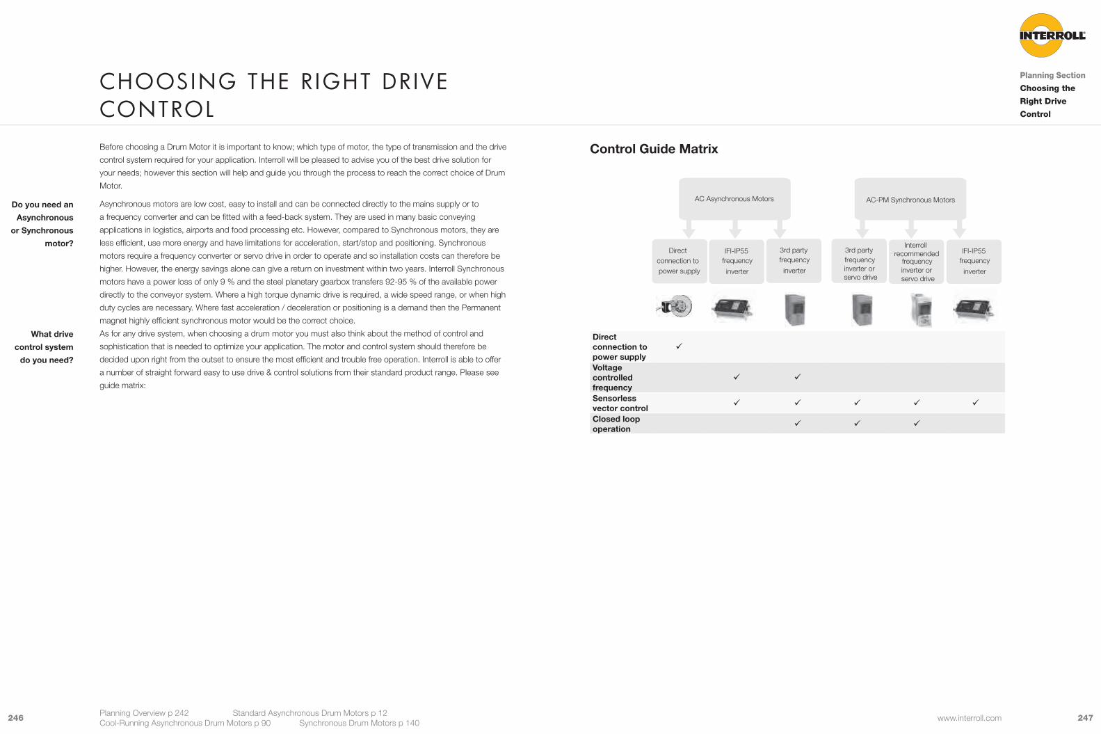
247246 www.interroll.com
Direct connection to power supply
9
Voltage controlled frequency
9 9
Sensorless vector control 9 9 9 9 9
Closed loop operation 9 9 9
Direct connection to power supply
AC Asynchronous Motors AC-PM Synchronous Motors
3rd party
inverter
frequency3rd party
inverter or servo drive
frequency
Interroll recommended
inverter or servo drive
frequency IFI-IP55
inverter
frequency IFI-IP55
inverter
frequency
Before choosing a Drum Motor it is important to know; which type of motor, the type of transmission and the drive
control system required for your application. Interroll will be pleased to advise you of the best drive solution for
your needs; however this section will help and guide you through the process to reach the correct choice of Drum
Motor.
Asynchronous motors are low cost, easy to install and can be connected directly to the mains supply or to
a frequency converter and can be fitted with a feed-back system. They are used in many basic conveying
applications in logistics, airports and food processing etc. However, compared to Synchronous motors, they are
less efficient, use more energy and have limitations for acceleration, start/stop and positioning. Synchronous
motors require a frequency converter or servo drive in order to operate and so installation costs can therefore be
higher. However, the energy savings alone can give a return on investment within two years. Interroll Synchronous
motors have a power loss of only 9 % and the steel planetary gearbox transfers 92-95 % of the available power
directly to the conveyor system. Where a high torque dynamic drive is required, a wide speed range, or when high
duty cycles are necessary. Where fast acceleration / deceleration or positioning is a demand then the Permanent
magnet highly efficient synchronous motor would be the correct choice.
As for any drive system, when choosing a drum motor you must also think about the method of control and
sophistication that is needed to optimize your application. The motor and control system should therefore be
decided upon right from the outset to ensure the most efficient and trouble free operation. Interroll is able to offer
a number of straight forward easy to use drive & control solutions from their standard product range. Please see
guide matrix:
Do you need an
Asynchronous
or Synchronous
motor?
What drive
control system
do you need?
ChoosInG the r IGht DrIve Control
Planning Overview p 242 Standard Asynchronous Drum Motors p 12 Cool-Running Asynchronous Drum Motors p 90 Synchronous Drum Motors p 140
Planning Section
Choosing the
Right Drive
Control
Control Guide Matrix

249248 www.interroll.com
Positive Drive Belts
Plastic modular belts, solid homogeneous belts, steel mesh or wire belts are positively driven with no tension.
Because the belt has no direct contact with the drum shell, heat dissipation is less effective and therefore the drum
motor should be used in conjunction with a frequency converter optimised for cool-running. Alternatively a cool-
running or synchronous drum motor can be used.
Positive drive belts use less power consumption than friction drive belts, allowing longer conveyor constructions.
Because these belts are not tensioned, there is less stress on the bearings and internal parts of the drum motor
resulting in a longer service life.
• i-series standard asynchronous drum motors 80i to 217i with frequency converter
• Cool-running asynchronous drum motors
• Synchronous drum motors
• When sprockets are required, choose cylindrical shell with key
• When using a frequency converter for asynchronous drum motors, it is important to use its setup function to
derate the motor and prevent thermal overload
Interroll recommends the use of profiled lagging wherever possible, resulting in easy cleaning, evenly distributed
torque transmission and torque dampening at start-up. Stainless steel or techno-polymer sprockets can be
supplied for belts where profiled lagging is not suitable.
Interroll offers a wide range of profiled lagging according to the belt manufacturers’ specifications.
For more detailed information, refer to p 283.
Suitable drum
motors
Torque
transmission
Lagging
Most Interroll Drum Motors are used for unit handling conveyors to handle packages, boxes, cartons, small pallets,
or any other unit format. Either friction or positive drive belts can be used with standard/derated asynchronous
drum motors or synchronous drum motors, depending on your application.
Examples of applications:
• Logistics, such as postal sorting, distribution centres
• Airport baggage handling
• Seafood, meat and poultry
• Bakeries
• Fruit and vegetables
• Beverage and brewing industry
• Snacks
• Packaging weighing equipment
Friction Drive Belts
Friction drive belts use the friction between the drum motor shell and belt to drive the belt. The drum motor is
normally crowned to prevent belt wander. The belt must be tensioned in order to transmit the torque from the drum
motor. The top surface of the belt can be flat, plain or have a ribbed, grooved or diamond pattern.
• Standard asynchronous drum motors with crowned shell
• Cool-running asynchronous drum motors with crowned shell
• Synchronous drum motors with crowned shell
Crowning of the shell is the simplest way to ensure central belt tracking.
Interroll supplies a complete range of hot or cold vulcanised lagging in various materials in order to increase friction
between the belt and drum shell.
For more detailed information, refer to p 267.
Suitable drum
motor
Torque
transmission
Lagging
appl ICatIon basICsPlanning Section
Application
Basics
Planning Overview p 242 Standard Asynchronous Drum Motors p 12 Cool-Running Asynchronous Drum Motors p 90 Synchronous Drum Motors p 140
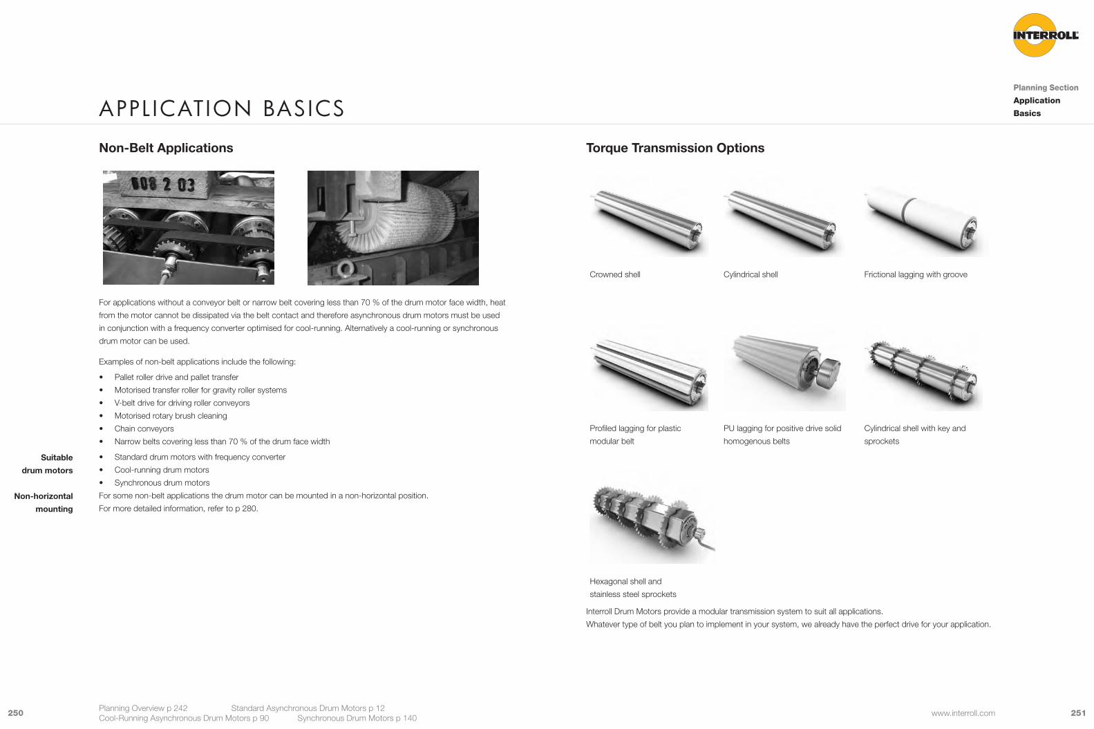
251250 www.interroll.com
Torque Transmission Options
Crowned shell Cylindrical shell Frictional lagging with groove
Profiled lagging for plastic
modular belt
PU lagging for positive drive solid
homogenous belts
Cylindrical shell with key and
sprockets
Hexagonal shell and
stainless steel sprockets
Interroll Drum Motors provide a modular transmission system to suit all applications.
Whatever type of belt you plan to implement in your system, we already have the perfect drive for your application.
Non-Belt Applications
For applications without a conveyor belt or narrow belt covering less than 70 % of the drum motor face width, heat
from the motor cannot be dissipated via the belt contact and therefore asynchronous drum motors must be used
in conjunction with a frequency converter optimised for cool-running. Alternatively a cool-running or synchronous
drum motor can be used.
Examples of non-belt applications include the following:
• Pallet roller drive and pallet transfer
• Motorised transfer roller for gravity roller systems
• V-belt drive for driving roller conveyors
• Motorised rotary brush cleaning
• Chain conveyors
• Narrow belts covering less than 70 % of the drum face width
• Standard drum motors with frequency converter
• Cool-running drum motors
• Synchronous drum motors
For some non-belt applications the drum motor can be mounted in a non-horizontal position.
For more detailed information, refer to p 280.
Suitable
drum motors
Non-horizontal
mounting
appl ICatIon basICsPlanning Section
Application
Basics
Planning Overview p 242 Standard Asynchronous Drum Motors p 12 Cool-Running Asynchronous Drum Motors p 90 Synchronous Drum Motors p 140

253252 www.interroll.com
Hygienic Design
All Interroll Drum Motors are designed in accordance with EU Directives for Hygienic Design:
• Machinery Directive (Directive 98/37/EC) Food Machinery section, Appendix 1, point 2.1
(to be replaced by 2006/42/EC)
• Document 13 EHEDG-Guideline to the hygienic design of apparatus for open processes, prepared in collabo-
ration with 3-A and NSF International (Only D-Series)
Interroll D-Series Drum Motors configured with components listed below, comply with EHEDG, Class
I “Open Equipment”. They are ideally suited for ultra-hygienic environments and tolerate high water
pressure wash down up to IP 69K:
• Stainless Steel shell: Cylindrical or Crowned or hexagonal - Electro polished
• Stainless end housings
• Stainless steel extended shafts (EL-FW =25 mm)
• PTFE / Gylon shaft sealing’s
• Rittal Stainless Steel Cable Gland Hygienic Design
• Food grade synthetic oil
According to EHEDG design rules, it is highly recommended to incorporate rust-free open conveyor frames to
facilitate easy cleaning, wash down and disinfection of the conveyor, drum motor and belt. The hygienic mounting
of the drum motor in the conveyor frame should be done in such a way that the contact between motor shaft and
the frame support does not have any metal-to-metal contact, i.e. by using an elastomer sealing between shaft and
frame support. The rubber material shall be FDA and EC1935/2004 compliant.
Cleaning specialist Ecolab has certified a 5-year minimum lifetime of materials used for Interroll Drum Motor series
S, i and D when exposed to typical cleaning and disinfecting procedures using Ecolab‘s Topax range of products:
P3-topax 19, P3-topax 686, P3-topax 56 and P3-topactive DES.
EHEDG
designed
Drum Motors
Conveyor Frame
Cleaning
Materials
Hygienic Conditions
For food processing and other applications where hygiene is paramount we recommend the following materials,
connectors and accessories:
• Stainless steel shell
• Stainless steel or Aluminium end housings
• Stainless steel shafts
• Stainless external re-greasable steel labyrinths (i-series)
• PTFE / Gylon external shaft seals (D-series)
• NBR external deflection seals (S-series)
• Food grade synthetic oil
• Hot vulcanised NBR (FDA & (EC) 1935/2004)
• Cold vulcanised NBR (FDA only)
• Cold vulcanised NBR ( (EC)1935/2004 only)
• Moulded PU - Shore hardness 80D ((EC) 1935/2004 only)
• Mild Steel shell can be used only with hot vulcanised NBR or moulded PU lagging
• Diamond patterned lagging is not suitable for food processing applications
All cable connectors, terminal boxes and cables are not included in our (EC) 1935/2004 and FDA declaration.
These components are considered “Not in direct contact with food stuffs“ as described in the following regulations:
Commission regulation (EC) No. 2023/2006 of 22nd December 2006 on good manufacturing practice for materials
and articles intended to come into contact with food. Article 3, definition (d): ‚non-food-contact side‘ means “the
surface of the material or article that is not directly in contact with food“.
FDA Food Code 2009: Chapter 1 - Purpose and Definitions - “Food-contact surface“ means:
• (1) A surface of equipment or a utensil with which food normally comes into contact; or
• (2) A surface of equipment or a utensil from which food may drain, drip, or splash: - (a) Into a food, or
- (b) onto a surface normally in contact with food.
NSF: On request
USDA & 3A: no complicance
For food processing applications, Interroll recommends using cable connectors and terminal boxes in stainless
steel or technopolymer.
Cable connectors
Terminal Boxes
and cables
envIronmental ConDItIonsPlanning Section
Environmental
Conditions
Planning Overview p 242 Standard Asynchronous Drum Motors p 12 Cool-Running Asynchronous Drum Motors p 90 Synchronous Drum Motors p 140
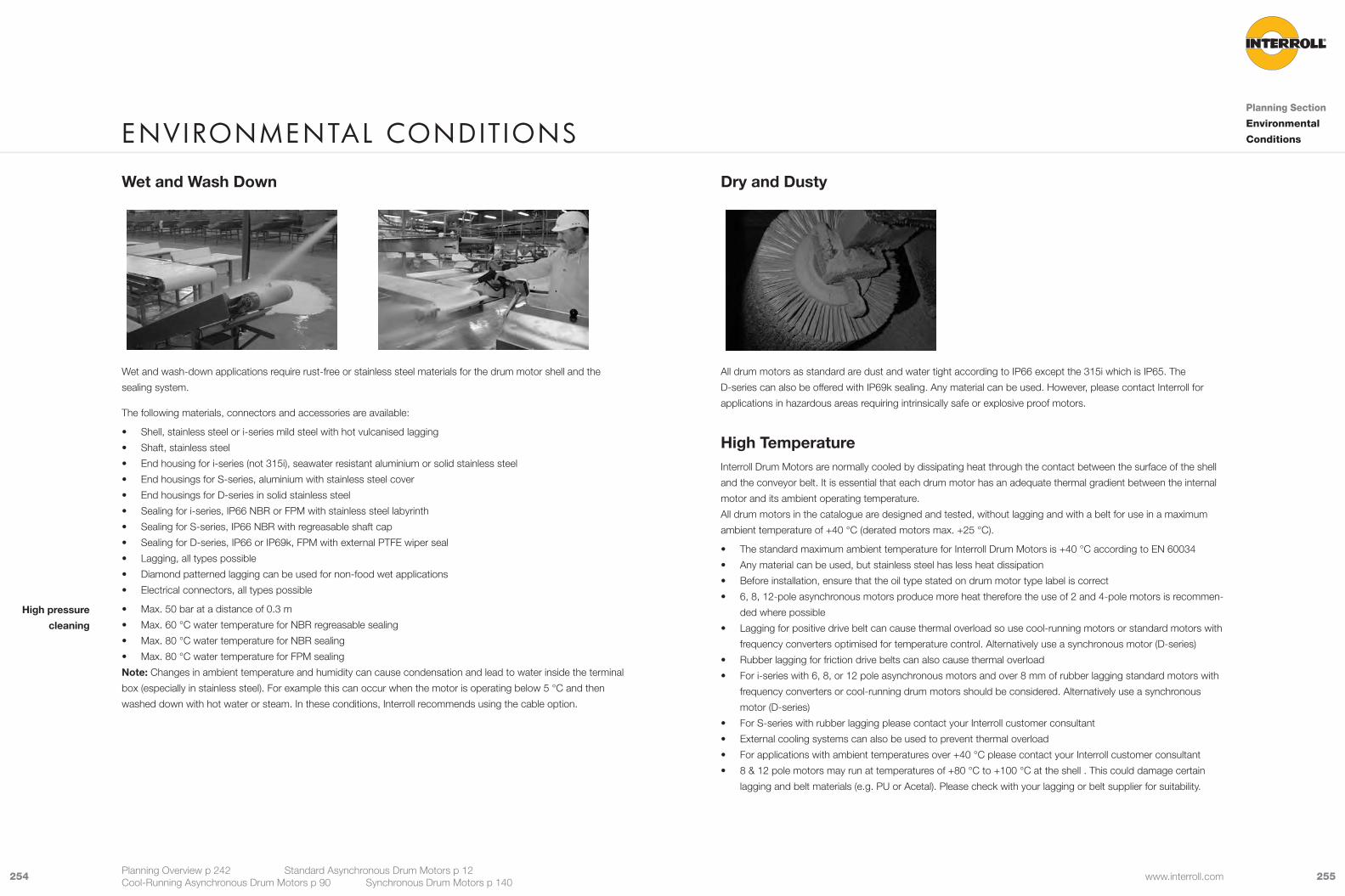
255254 www.interroll.com
Dry and Dusty
All drum motors as standard are dust and water tight according to IP66 except the 315i which is IP65. The
D-series can also be offered with IP69k sealing. Any material can be used. However, please contact Interroll for
applications in hazardous areas requiring intrinsically safe or explosive proof motors.
High TemperatureInterroll Drum Motors are normally cooled by dissipating heat through the contact between the surface of the shell
and the conveyor belt. It is essential that each drum motor has an adequate thermal gradient between the internal
motor and its ambient operating temperature.
All drum motors in the catalogue are designed and tested, without lagging and with a belt for use in a maximum
ambient temperature of +40 °C (derated motors max. +25 °C).
• The standard maximum ambient temperature for Interroll Drum Motors is +40 °C according to EN 60034
• Any material can be used, but stainless steel has less heat dissipation
• Before installation, ensure that the oil type stated on drum motor type label is correct
• 6, 8, 12-pole asynchronous motors produce more heat therefore the use of 2 and 4-pole motors is recommen-
ded where possible
• Lagging for positive drive belt can cause thermal overload so use cool-running motors or standard motors with
frequency converters optimised for temperature control. Alternatively use a synchronous motor (D-series)
• Rubber lagging for friction drive belts can also cause thermal overload
• For i-series with 6, 8, or 12 pole asynchronous motors and over 8 mm of rubber lagging standard motors with
frequency converters or cool-running drum motors should be considered. Alternatively use a synchronous
motor (D-series)
• For S-series with rubber lagging please contact your Interroll customer consultant
• External cooling systems can also be used to prevent thermal overload
• For applications with ambient temperatures over +40 °C please contact your Interroll customer consultant
• 8 & 12 pole motors may run at temperatures of +80 °C to +100 °C at the shell . This could damage certain
lagging and belt materials (e.g. PU or Acetal). Please check with your lagging or belt supplier for suitability.
Wet and Wash Down
Wet and wash-down applications require rust-free or stainless steel materials for the drum motor shell and the
sealing system.
The following materials, connectors and accessories are available:
• Shell, stainless steel or i-series mild steel with hot vulcanised lagging
• Shaft, stainless steel
• End housing for i-series (not 315i), seawater resistant aluminium or solid stainless steel
• End housings for S-series, aluminium with stainless steel cover
• End housings for D-series in solid stainless steel
• Sealing for i-series, IP66 NBR or FPM with stainless steel labyrinth
• Sealing for S-series, IP66 NBR with regreasable shaft cap
• Sealing for D-series, IP66 or IP69k, FPM with external PTFE wiper seal
• Lagging, all types possible
• Diamond patterned lagging can be used for non-food wet applications
• Electrical connectors, all types possible
• Max. 50 bar at a distance of 0.3 m
• Max. 60 °C water temperature for NBR regreasable sealing
• Max. 80 °C water temperature for NBR sealing
• Max. 80 °C water temperature for FPM sealing
Note: Changes in ambient temperature and humidity can cause condensation and lead to water inside the terminal
box (especially in stainless steel). For example this can occur when the motor is operating below 5 °C and then
washed down with hot water or steam. In these conditions, Interroll recommends using the cable option.
High pressure
cleaning
envIronmental ConDItIonsPlanning Section
Environmental
Conditions
Planning Overview p 242 Standard Asynchronous Drum Motors p 12 Cool-Running Asynchronous Drum Motors p 90 Synchronous Drum Motors p 140

257256 www.interroll.com
You will find information for selection of the correct voltage in the motor version tables. The values listed are
average values, which can be increased or decreased depending on the required motor temperature and the
ambient temperature. Interroll would strongly recommend selecting the correct voltage by testing under actual
operating conditions.
Only DC voltage may be used to heat the motor. The use of AC voltage can cause the motor to move unexpectedly
leading to serious damage or injury.
The stationary heating system should only be used when the motor is actually idle. The heating voltage must be
switched off before the motor is operated. This can be safely done using simple relays or switches.
The suggested voltages are calculated to prevent the formation of condensation. If the motor needs to be held at a
specific temperature, then the stationary heating system must be set up accordingly. In cases, such as this, please
contact your Interroll customer consultant.
The anti-condensation heating voltage must be connected to any two phases of a 3-phase motor. The heating
current supplied by the power supply can be calculated as follows:
Delta connection:
IDC =VSHdelta
. 3
RMotor . 2
Star connection:
RMotor . 2
VSHstarIDC =
Low Noise
All Interroll Drum Motors have relatively low noise and vibration levels. The performance levels are not specified or
guaranteed in this catalogue because this can vary depending on the type of motor, poles, speed and application.
For specific low-noise applications please contact your Interroll customer consultant.
Low TemperatureWhen a drum motor is operated in low temperatures (less than +5 °C), consider the viscosity of the oil and
temperature of the motor while it is not running. Consider also that condensation may occur with varying
temperatures.
We would recommend the following materials, connectors and accessories:
• Shell, stainless steel, hot vulcanized lagging. For i-Series hot vulcanized lagging can be used with mild steel shell
• Shaft, stainless steel
• End housing for i-series (not 315i), seawater resistant aluminium or solid stainless steel
• End housings for s-series, aluminium with or without stainless steel cover
• End housings for D-series in stainless steel
• Sealing for i-series, stainless steel with labyrinth
• Sealing for S-series, regreasable shaft cap
• Use low temperature oil
• Use special low temperature seals in temperatures below -25 °C (for i-series and D-series only)
• S- and i-Series single phase motors may have starting issues and are not recommended for use in temperatu-
res below+10 °C
• Activate the anti-condensation heating (asynchronous motors only)
• Lagging, all types possible
• Minus temperatures reduce effectiveness of friction lagging
• Electrical connectors, all types but avoid terminal boxes, if possible
• Cables that are subject to continuous movement in minus temperatures can suffer structural damage. In such
applications, special cable material, like PU, is required
• Use rust-free materials
Anti-condensation heating for Asynchronous Drum Motors
In ambient temperatures below +1 °C, consider heating the motor windings to keep the oil viscosity, seals and
internal parts at a constant temperature.
If the motor current is switched off for some time and the ambient temperature is very low, then the motor oil
becomes viscous. In these conditions problems may occur when starting the motor and at temperatures of around
zero frost crystals can form on the sealing surfaces causing oil leakage. To prevent these problems use anti-
condensation heating.
The heating system applies a DC voltage to the motor winding, which in turn causes current to flow either in the
two motor phases of a 3-phase motor or the main winding of a single-phase motor. The magnitude of the current
is set by the magnitude of the voltage applied and the winding resistance. This current causes power loss in the
winding which heats the motor to a temperature dependent on the ambient temperature and the magnitude of the
current.
envIronmental ConDItIonsPlanning Section
Environmental
Conditions
Planning Overview p 242 Standard Asynchronous Drum Motors p 12 Cool-Running Asynchronous Drum Motors p 90 Synchronous Drum Motors p 140
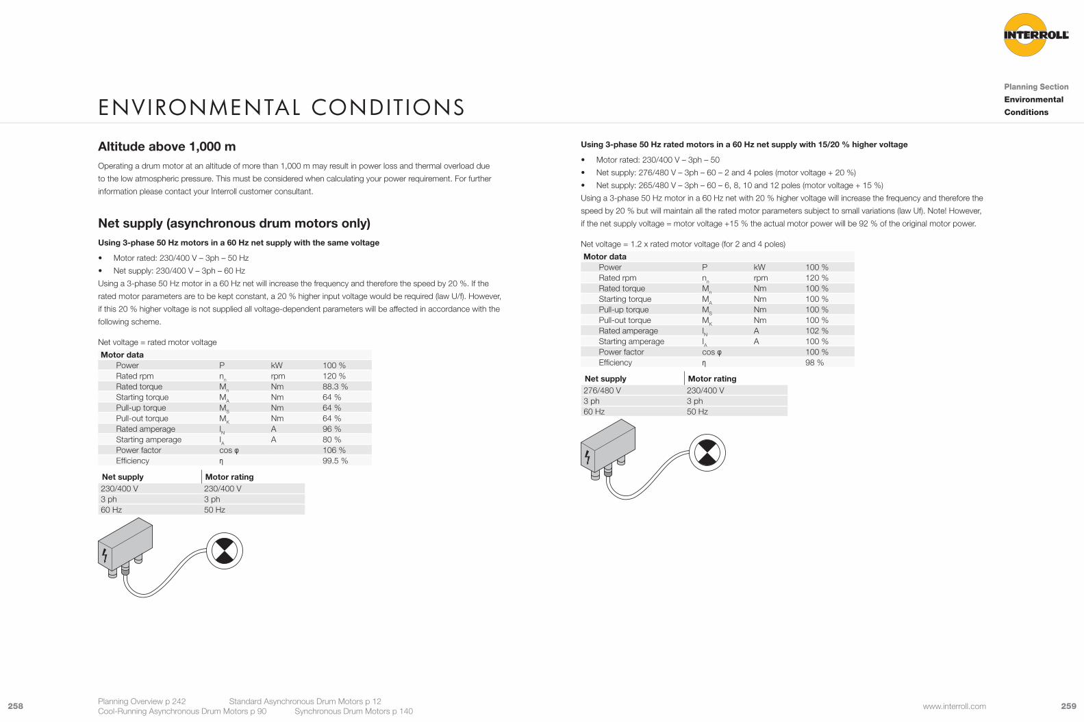
259258 www.interroll.com
Using 3-phase 50 Hz rated motors in a 60 Hz net supply with 15/20 % higher voltage
• Motor rated: 230/400 V – 3ph – 50
• Net supply: 276/480 V – 3ph – 60 – 2 and 4 poles (motor voltage + 20 %)
• Net supply: 265/480 V – 3ph – 60 – 6, 8, 10 and 12 poles (motor voltage + 15 %)
Using a 3-phase 50 Hz motor in a 60 Hz net with 20 % higher voltage will increase the frequency and therefore the
speed by 20 % but will maintain all the rated motor parameters subject to small variations (law Uf). Note! However,
if the net supply voltage = motor voltage +15 % the actual motor power will be 92 % of the original motor power.
Net voltage = 1.2 x rated motor voltage (for 2 and 4 poles)
Motor dataPower P kW 100 %Rated rpm nn rpm 120 %Rated torque Mn Nm 100 %Starting torque MA Nm 100 %Pull-up torque MS Nm 100 %Pull-out torque MK Nm 100 %Rated amperage IN A 102 %Starting amperage IA A 100 %Power factor cos φ 100 %Efficiency η 98 %
Net supply Motor rating276/480 V 230/400 V3 ph 3 ph60 Hz 50 Hz
Altitude above 1,000 mOperating a drum motor at an altitude of more than 1,000 m may result in power loss and thermal overload due
to the low atmospheric pressure. This must be considered when calculating your power requirement. For further
information please contact your Interroll customer consultant.
Net supply (asynchronous drum motors only)Using 3-phase 50 Hz motors in a 60 Hz net supply with the same voltage
• Motor rated: 230/400 V – 3ph – 50 Hz
• Net supply: 230/400 V – 3ph – 60 Hz
Using a 3-phase 50 Hz motor in a 60 Hz net will increase the frequency and therefore the speed by 20 %. If the
rated motor parameters are to be kept constant, a 20 % higher input voltage would be required (law U/f). However,
if this 20 % higher voltage is not supplied all voltage-dependent parameters will be affected in accordance with the
following scheme.
Net voltage = rated motor voltage
Motor dataPower P kW 100 %Rated rpm nn rpm 120 %Rated torque Mn Nm 88.3 %Starting torque MA Nm 64 %Pull-up torque MS Nm 64 %Pull-out torque MK Nm 64 %Rated amperage IN A 96 %Starting amperage IA A 80 %Power factor cos φ 106 %Efficiency η 99.5 %
Net supply Motor rating230/400 V 230/400 V3 ph 3 ph60 Hz 50 Hz
envIronmental ConDItIonsPlanning Section
Environmental
Conditions
Planning Overview p 242 Standard Asynchronous Drum Motors p 12 Cool-Running Asynchronous Drum Motors p 90 Synchronous Drum Motors p 140
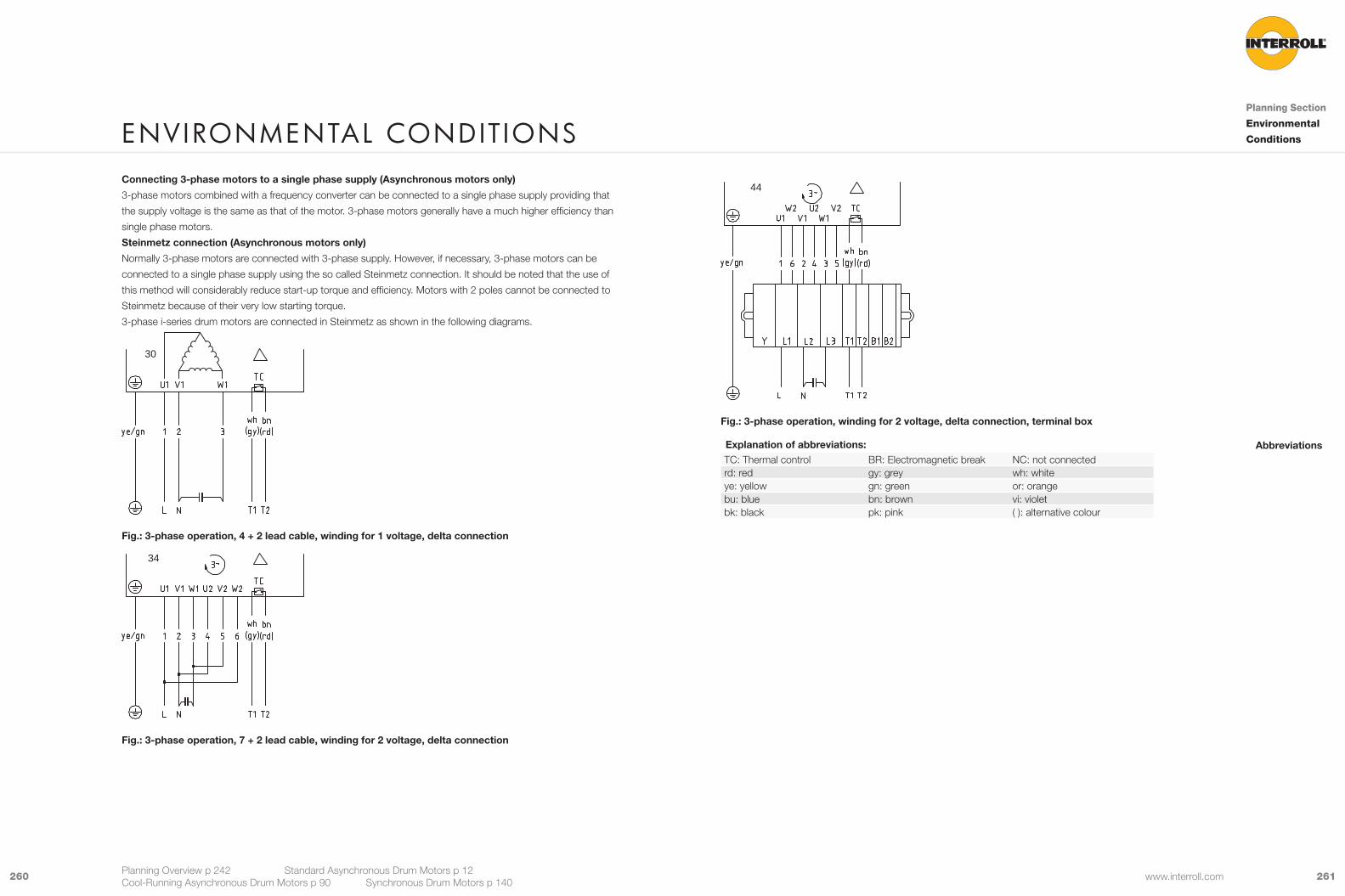
261260 www.interroll.com
44
Fig.: 3-phase operation, winding for 2 voltage, delta connection, terminal box
Explanation of abbreviations:TC: Thermal control BR: Electromagnetic break NC: not connectedrd: red gy: grey wh: whiteye: yellow gn: green or: orangebu: blue bn: brown vi: violetbk: black pk: pink ( ): alternative colour
Abbreviations
Connecting 3-phase motors to a single phase supply (Asynchronous motors only)
3-phase motors combined with a frequency converter can be connected to a single phase supply providing that
the supply voltage is the same as that of the motor. 3-phase motors generally have a much higher efficiency than
single phase motors.
Steinmetz connection (Asynchronous motors only)
Normally 3-phase motors are connected with 3-phase supply. However, if necessary, 3-phase motors can be
connected to a single phase supply using the so called Steinmetz connection. It should be noted that the use of
this method will considerably reduce start-up torque and efficiency. Motors with 2 poles cannot be connected to
Steinmetz because of their very low starting torque.
3-phase i-series drum motors are connected in Steinmetz as shown in the following diagrams.
30
Fig.: 3-phase operation, 4 + 2 lead cable, winding for 1 voltage, delta connection
34
Fig.: 3-phase operation, 7 + 2 lead cable, winding for 2 voltage, delta connection
envIronmental ConDItIonsPlanning Section
Environmental
Conditions
Planning Overview p 242 Standard Asynchronous Drum Motors p 12 Cool-Running Asynchronous Drum Motors p 90 Synchronous Drum Motors p 140
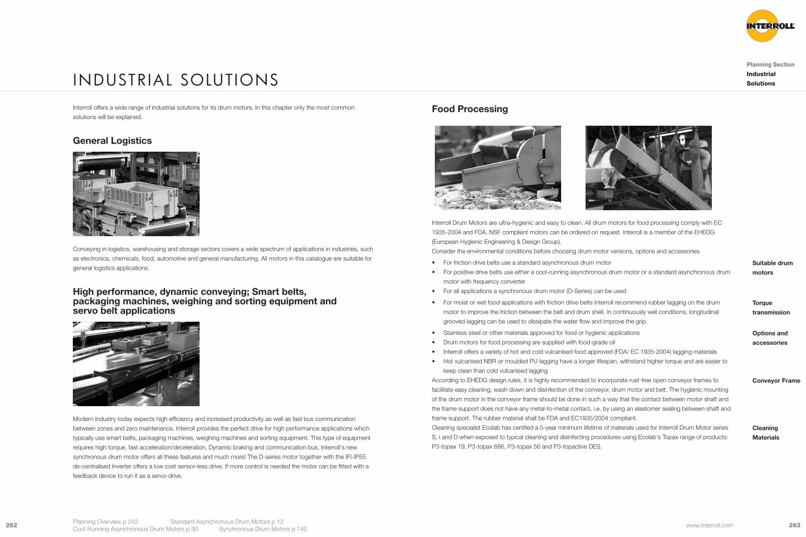
263262 www.interroll.com
Food Processing
Interroll Drum Motors are ultra-hygienic and easy to clean. All drum motors for food processing comply with EC
1935-2004 and FDA. NSF complient motors can be ordered on request. Interroll is a member of the EHEDG
(European Hygienic Engineering & Design Group).
Consider the environmental conditions before choosing drum motor versions, options and accessories.
• For friction drive belts use a standard asynchronous drum motor
• For positive drive belts use either a cool-running asynchronous drum motor or a standard asynchronous drum
motor with frequency converter
• For all applications a synchronous drum motor (D-Series) can be used
• For moist or wet food applications with friction drive belts Interroll recommend rubber lagging on the drum
motor to improve the friction between the belt and drum shell. In continuously wet conditions, longitudinal
grooved lagging can be used to dissipate the water flow and improve the grip
• Stainless steel or other materials approved for food or hygienic applications
• Drum motors for food processing are supplied with food-grade oil
• Interroll offers a variety of hot and cold vulcanised food approved (FDA/ EC 1935-2004) lagging materials
• Hot vulcanised NBR or moulded PU lagging have a longer lifespan, withstand higher torque and are easier to
keep clean than cold vulcanised lagging
According to EHEDG design rules, it is highly recommended to incorporate rust-free open conveyor frames to
facilitate easy cleaning, wash down and disinfection of the conveyor, drum motor and belt. The hygienic mounting
of the drum motor in the conveyor frame should be done in such a way that the contact between motor shaft and
the frame support does not have any metal-to-metal contact, i.e. by using an elastomer sealing between shaft and
frame support. The rubber material shall be FDA and EC1935/2004 compliant.
Cleaning specialist Ecolab has certified a 5-year minimum lifetime of materials used for Interroll Drum Motor series
S, i and D when exposed to typical cleaning and disinfecting procedures using Ecolab‘s Topax range of products:
P3-topax 19, P3-topax 686, P3-topax 56 and P3-topactive DES.
Suitable drum
motors
Torque
transmission
Options and
accessories
Conveyor Frame
Cleaning
Materials
Interroll offers a wide range of industrial solutions for its drum motors. In this chapter only the most common
solutions will be explained.
General Logistics
Conveying in logistics, warehousing and storage sectors covers a wide spectrum of applications in industries, such
as electronics, chemicals, food, automotive and general manufacturing. All motors in this catalogue are suitable for
general logistics applications.
High performance, dynamic conveying; Smart belts, packaging machines, weighing and sorting equipment and servo belt applications
Modern Industry today expects high efficiency and increased productivity as well as fast bus communication
between zones and zero maintenance. Interroll provides the perfect drive for high performance applications which
typically use smart belts, packaging machines, weighing machines and sorting equipment. This type of equipment
requires high torque, fast acceleration/deceleration, Dynamic braking and communication bus. Interroll‘s new
synchronous drum motor offers all these features and much more! The D-series motor together with the IFI-IP55
de-centralised Inverter offers a low cost sensor-less drive. If more control is needed the motor can be fitted with a
feedback device to run it as a servo-drive.
InDustrIal solutIonsPlanning Section
Industrial
Solutions
Planning Overview p 242 Standard Asynchronous Drum Motors p 12 Cool-Running Asynchronous Drum Motors p 90 Synchronous Drum Motors p 140

265264 www.interroll.com
Supermarket Checkouts
A wide variety of packed foods, confectionery and electrical goods are carried on supermarket checkout
conveyors. Frequent start/stops and low noise are typical for this type of application with friction drive belts.
• Drum motors 80S and 113S
• Interroll offers drum motors which are optimised specifically for supermarket checkouts (Please request the
C-series catalogue)
• Plug-in cable connectors (C-Versions only)
• Primarily single phase supply, 3-phase as an option
Suitable drum
motors
Options and
accessories
Airport Logistics
Airport applications, such as check-in conveyors, X-Ray machines and scanning equipment, require low noise and
frequent starts and stops. Most applications use friction drive belts made of PU, PVC or rubber.
• Standard drum motors with 4 or 6 poles offer low noise levels that are typically below 56 dB. Lower noise
levels can be supplied on request
• Baggage handling systems (138i-315i)
• X-Ray machines (113S, 113i, 138i)
• Check in conveyors (113i, 138i, 113S)
• 4-pole motors generally offer higher efficiency
• Lagging for friction drive belts to increase friction
• Backstops for inclined conveyors
• Brakes for holding the belt stationary
• Halogen-free cables available
Suitable drum
motors
InDustrIal solutIonsPlanning Section
Industrial
Solutions
Planning Overview p 242 Standard Asynchronous Drum Motors p 12 Cool-Running Asynchronous Drum Motors p 90 Synchronous Drum Motors p 140
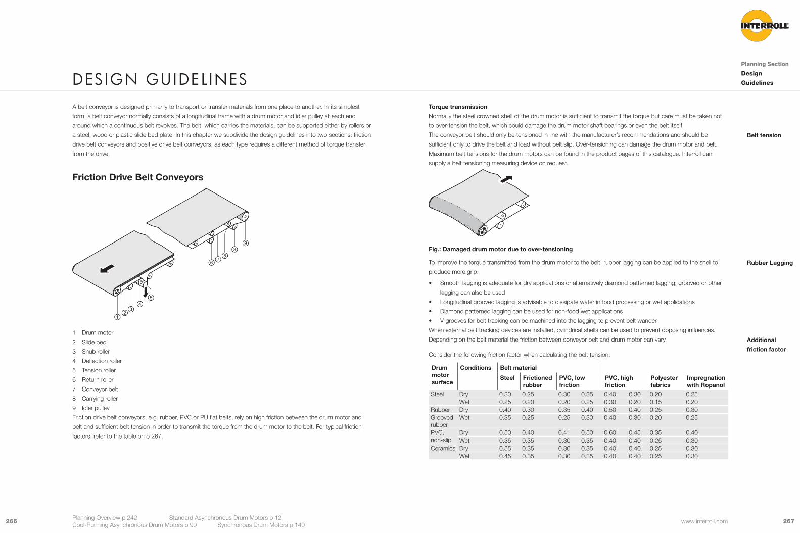
267266 www.interroll.com
Torque transmission
Normally the steel crowned shell of the drum motor is sufficient to transmit the torque but care must be taken not
to over-tension the belt, which could damage the drum motor shaft bearings or even the belt itself.
The conveyor belt should only be tensioned in line with the manufacturer’s recommendations and should be
sufficient only to drive the belt and load without belt slip. Over-tensioning can damage the drum motor and belt.
Maximum belt tensions for the drum motors can be found in the product pages of this catalogue. Interroll can
supply a belt tensioning measuring device on request.
Fig.: Damaged drum motor due to over-tensioning
To improve the torque transmitted from the drum motor to the belt, rubber lagging can be applied to the shell to
produce more grip.
• Smooth lagging is adequate for dry applications or alternatively diamond patterned lagging; grooved or other
lagging can also be used
• Longitudinal grooved lagging is advisable to dissipate water in food processing or wet applications
• Diamond patterned lagging can be used for non-food wet applications
• V-grooves for belt tracking can be machined into the lagging to prevent belt wander
When external belt tracking devices are installed, cylindrical shells can be used to prevent opposing influences.
Depending on the belt material the friction between conveyor belt and drum motor can vary.
Consider the following friction factor when calculating the belt tension:
Drum motor surface
Conditions Belt material
Steel Frictioned rubber
PVC, low friction
PVC, high friction
Polyester fabrics
Impregnation with Ropanol
Steel Dry 0.30 0.25 0.30 0.35 0.40 0.30 0.20 0.25Wet 0.25 0.20 0.20 0.25 0.30 0.20 0.15 0.20
Rubber Dry 0.40 0.30 0.35 0.40 0.50 0.40 0.25 0.30Grooved rubber
Wet 0.35 0.25 0.25 0.30 0.40 0.30 0.20 0.25
PVC, non-slip
Dry 0.50 0.40 0.41 0.50 0.60 0.45 0.35 0.40Wet 0.35 0.35 0.30 0.35 0.40 0.40 0.25 0.30
Ceramics Dry 0.55 0.35 0.30 0.35 0.40 0.40 0.25 0.30Wet 0.45 0.35 0.30 0.35 0.40 0.40 0.25 0.30
Belt tension
Rubber Lagging
Additional
friction factor
A belt conveyor is designed primarily to transport or transfer materials from one place to another. In its simplest
form, a belt conveyor normally consists of a longitudinal frame with a drum motor and idler pulley at each end
around which a continuous belt revolves. The belt, which carries the materials, can be supported either by rollers or
a steel, wood or plastic slide bed plate. In this chapter we subdivide the design guidelines into two sections: friction
drive belt conveyors and positive drive belt conveyors, as each type requires a different method of torque transfer
from the drive.
Friction Drive Belt Conveyors
1 Drum motor
2 Slide bed
3 Snub roller
4 Deflection roller
5 Tension roller
6 Return roller
7 Conveyor belt
8 Carrying roller
9 Idler pulley
Friction drive belt conveyors, e.g. rubber, PVC or PU flat belts, rely on high friction between the drum motor and
belt and sufficient belt tension in order to transmit the torque from the drum motor to the belt. For typical friction
factors, refer to the table on p 267.
DesIGn GuIDel InesPlanning Section
Design
Guidelines
Planning Overview p 242 Standard Asynchronous Drum Motors p 12 Cool-Running Asynchronous Drum Motors p 90 Synchronous Drum Motors p 140
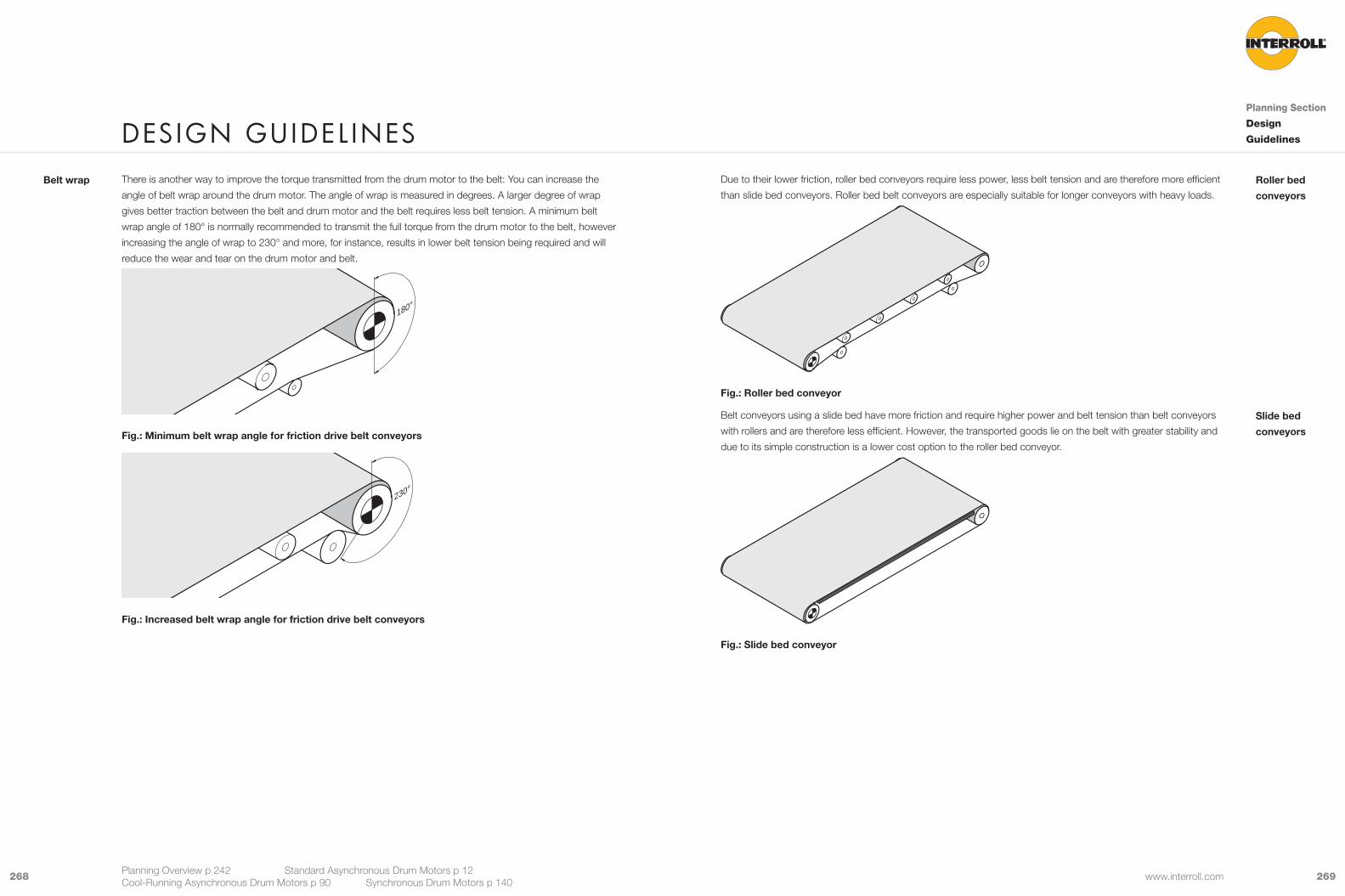
269268 www.interroll.com
Due to their lower friction, roller bed conveyors require less power, less belt tension and are therefore more efficient
than slide bed conveyors. Roller bed belt conveyors are especially suitable for longer conveyors with heavy loads.
Fig.: Roller bed conveyor
Belt conveyors using a slide bed have more friction and require higher power and belt tension than belt conveyors
with rollers and are therefore less efficient. However, the transported goods lie on the belt with greater stability and
due to its simple construction is a lower cost option to the roller bed conveyor.
Fig.: Slide bed conveyor
Roller bed
conveyors
Slide bed
conveyors
There is another way to improve the torque transmitted from the drum motor to the belt: You can increase the
angle of belt wrap around the drum motor. The angle of wrap is measured in degrees. A larger degree of wrap
gives better traction between the belt and drum motor and the belt requires less belt tension. A minimum belt
wrap angle of 180° is normally recommended to transmit the full torque from the drum motor to the belt, however
increasing the angle of wrap to 230° and more, for instance, results in lower belt tension being required and will
reduce the wear and tear on the drum motor and belt.
180°
Fig.: Minimum belt wrap angle for friction drive belt conveyors
230°
Fig.: Increased belt wrap angle for friction drive belt conveyors
Belt wrap
DesIGn GuIDel InesPlanning Section
Design
Guidelines
Planning Overview p 242 Standard Asynchronous Drum Motors p 12 Cool-Running Asynchronous Drum Motors p 90 Synchronous Drum Motors p 140

271270 www.interroll.com
Tail drive
The tail drive (loading or receiving end) is not the ideal drive position as the drum motor is pushing the top carrying
side of the belt and more tension is applied to the return belt, therefore the full torque of the drive may not be
applied. This type of drive can lead to belt waves (belt lifting on the top side), jumping and undesirable belt wander.
If a tail drive is necessary, it is recommended only for use with short friction drive belt conveyors up to 2 or 3 metres
in length with light loads. (It is not recommended for positive drive belts).
Fig.: Short friction drive belt conveyor with tail drive
Centre drive
A centre drive can be used for longer belt conveyors where a large diameter drum motor is required and there is
insufficient space available at the head end. The centre drive can also be used for reversible conveyors where the
belt tension is distributed more evenly between the carrying and return side of the belt. Belt tracking issues for
forward and reverse operation can be minimised.
Fig.: Long belt conveyor with centre drive
The drum motor is usually positioned at the head or discharge end of the conveyor but can be positioned
elsewhere to suit the application or design.
Head drive
The head drive (discharge end) is the most common and preferred option for non-reversible conveyors and is ideal
because it is simple to design and easy to install. Furthermore most of the belt tension is on the top carrying side
and allows the drum motor to transfer its full torque to the belt.
Fig.: Non-reversible conveyor with head drive
Fig.: Optional design for non-reversible long conveyor with centre take-up
Drive positions
DesIGn GuIDel InesPlanning Section
Design
Guidelines
Planning Overview p 242 Standard Asynchronous Drum Motors p 12 Cool-Running Asynchronous Drum Motors p 90 Synchronous Drum Motors p 140
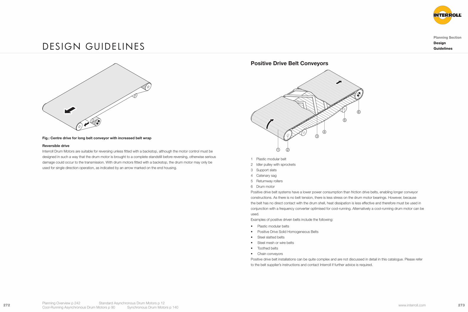
273272 www.interroll.com
Positive Drive Belt Conveyors
1 Plastic modular belt
2 Idler pulley with sprockets
3 Support slats
4 Catenary sag
5 Returnway rollers
6 Drum motor
Positive drive belt systems have a lower power consumption than friction drive belts, enabling longer conveyor
constructions. As there is no belt tension, there is less stress on the drum motor bearings. However, because
the belt has no direct contact with the drum shell, heat dissipation is less effective and therefore must be used in
conjunction with a frequency converter optimised for cool-running. Alternatively a cool-running drum motor can be
used.
Examples of positive driven belts include the following:
• Plastic modular belts
• Positive Drive Solid Homogeneous Belts
• Steel slatted belts
• Steel mesh or wire belts
• Toothed belts
• Chain conveyors
Positive drive belt installations can be quite complex and are not discussed in detail in this catalogue. Please refer
to the belt supplier’s instructions and contact Interroll if further advice is required.
Fig.: Centre drive for long belt conveyor with increased belt wrap
Reversible drive
Interroll Drum Motors are suitable for reversing unless fitted with a backstop, although the motor control must be
designed in such a way that the drum motor is brought to a complete standstill before reversing, otherwise serious
damage could occur to the transmission. With drum motors fitted with a backstop, the drum motor may only be
used for single direction operation, as indicated by an arrow marked on the end housing.
DesIGn GuIDel InesPlanning Section
Design
Guidelines
Planning Overview p 242 Standard Asynchronous Drum Motors p 12 Cool-Running Asynchronous Drum Motors p 90 Synchronous Drum Motors p 140
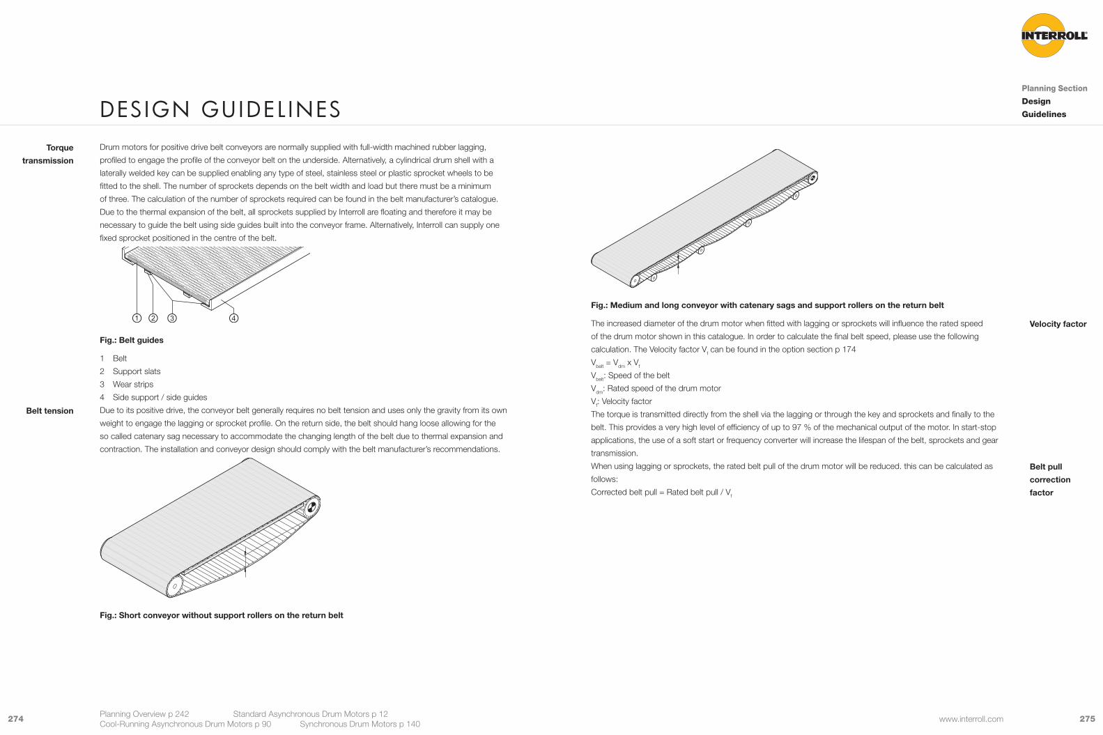
275274 www.interroll.com
Fig.: Medium and long conveyor with catenary sags and support rollers on the return belt
The increased diameter of the drum motor when fitted with lagging or sprockets will influence the rated speed
of the drum motor shown in this catalogue. In order to calculate the final belt speed, please use the following
calculation. The Velocity factor Vf can be found in the option section p 174
Vbelt = Vdm x Vf
Vbelt: Speed of the belt
Vdm: Rated speed of the drum motor
Vf: Velocity factor
The torque is transmitted directly from the shell via the lagging or through the key and sprockets and finally to the
belt. This provides a very high level of efficiency of up to 97 % of the mechanical output of the motor. In start-stop
applications, the use of a soft start or frequency converter will increase the lifespan of the belt, sprockets and gear
transmission.
When using lagging or sprockets, the rated belt pull of the drum motor will be reduced. this can be calculated as
follows:
Corrected belt pull = Rated belt pull / Vf
Velocity factor
Belt pull
correction
factor
Drum motors for positive drive belt conveyors are normally supplied with full-width machined rubber lagging,
profiled to engage the profile of the conveyor belt on the underside. Alternatively, a cylindrical drum shell with a
laterally welded key can be supplied enabling any type of steel, stainless steel or plastic sprocket wheels to be
fitted to the shell. The number of sprockets depends on the belt width and load but there must be a minimum
of three. The calculation of the number of sprockets required can be found in the belt manufacturer’s catalogue.
Due to the thermal expansion of the belt, all sprockets supplied by Interroll are floating and therefore it may be
necessary to guide the belt using side guides built into the conveyor frame. Alternatively, Interroll can supply one
fixed sprocket positioned in the centre of the belt.
Fig.: Belt guides
1 Belt
2 Support slats
3 Wear strips
4 Side support / side guides
Due to its positive drive, the conveyor belt generally requires no belt tension and uses only the gravity from its own
weight to engage the lagging or sprocket profile. On the return side, the belt should hang loose allowing for the
so called catenary sag necessary to accommodate the changing length of the belt due to thermal expansion and
contraction. The installation and conveyor design should comply with the belt manufacturer’s recommendations.
Fig.: Short conveyor without support rollers on the return belt
Torque
transmission
Belt tension
DesIGn GuIDel InesPlanning Section
Design
Guidelines
Planning Overview p 242 Standard Asynchronous Drum Motors p 12 Cool-Running Asynchronous Drum Motors p 90 Synchronous Drum Motors p 140
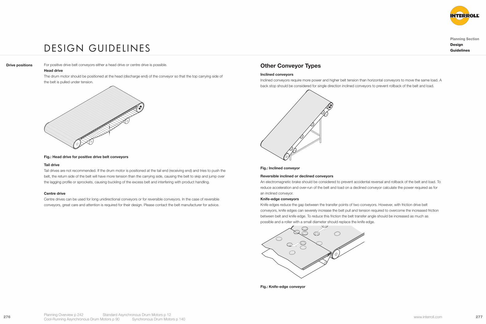
277276 www.interroll.com
Other Conveyor TypesInclined conveyors
Inclined conveyors require more power and higher belt tension than horizontal conveyors to move the same load. A
back stop should be considered for single direction inclined conveyors to prevent rollback of the belt and load.
Fig.: Inclined conveyor
Reversible inclined or declined conveyors
An electromagnetic brake should be considered to prevent accidental reversal and rollback of the belt and load. To
reduce acceleration and over-run of the belt and load on a declined conveyor calculate the power required as for
an inclined conveyor.
Knife-edge conveyors
Knife edges reduce the gap between the transfer points of two conveyors. However, with friction drive belt
conveyors, knife edges can severely increase the belt pull and tension required to overcome the increased friction
between belt and knife edge. To reduce this friction the belt transfer angle should be increased as much as
possible and a roller with a small diameter should replace the knife edge.
Fig.: Knife-edge conveyor
For positive drive belt conveyors either a head drive or centre drive is possible.
Head drive
The drum motor should be positioned at the head (discharge end) of the conveyor so that the top carrying side of
the belt is pulled under tension.
Fig.: Head drive for positive drive belt conveyors
Tail drive
Tail drives are not recommended. If the drum motor is positioned at the tail end (receiving end) and tries to push the
belt, the return side of the belt will have more tension than the carrying side, causing the belt to skip and jump over
the lagging profile or sprockets, causing buckling of the excess belt and interfering with product handling.
Centre drive
Centre drives can be used for long unidirectional conveyors or for reversible conveyors. In the case of reversible
conveyors, great care and attention is required for their design. Please contact the belt manufacturer for advice.
Drive positions
DesIGn GuIDel InesPlanning Section
Design
Guidelines
Planning Overview p 242 Standard Asynchronous Drum Motors p 12 Cool-Running Asynchronous Drum Motors p 90 Synchronous Drum Motors p 140

279278 www.interroll.com
Merges transfers and in-feed control
For asynchronous drum motors use a frequency converter with DC braking (with or without encoder) or
alternatively an electromagnetic brake to control the merge process. Alternatively, for precise, dynamic control and/
or high throughput, use a synchronous drum motor (D-Series).
Feed back system
Use an integrated encoder or other feedback device for precise speed and positioning (see p 290).
Operating Modes
The following operating modes comply with IEC 60034-1.
Continuous running duty S1
Operation at constant load which is long enough to reach a thermal steady-state condition.P
t
t
P
t
The majority of Interroll Drum Motor windings having an efficiency of over 0.5 are suitable for operating mode S1
and continuous running duty. Please refer to the electrical data tables for the standard or cool-running drum motors
under the sign η for efficiency.
Instead of using 6-, 8-, 12-pole motors for continuous running at low speed, consider using a 4-pole motor
(efficiency >0.5) with a frequency converter to obtain the required speed.
S2 to S10
For operation modes S2 to S10 consider duty cycles and consult Interroll.
Food processing conveyors
According to EHEDG design rules, it is highly recommended to incorporate rust-free open conveyor frames to
facilitate easy cleaning, wash down and disinfection of the conveyor, drum motor and belt.
Fig.: Open conveyor design for hygienic cleaning
Plough and diverter units
If a drum motor is installed in a plough or diverter unit, the drum motor will be positioned vertically, requiring a
special drum motor design with the cable always at the top (see p 280).
Frequent starts and stops
Frequent starts and stops can cause thermal overload of the motor and premature wear of the gear, reducing the
lifespan of the drum motor. In applications such as these, Interroll recommends the use of a frequency converter
to optimise the heat loss of the motor and use of the soft-start ramping facility to reduce the start-up load on the
gears. Synchronous or asynchronous drum motors with a IFI-IP55 driver (seep 238 ) are ideal for these applications.
Control SystemsInterroll supply brakes, backstops, feed back systems and frequency converters for their range of drum motors.
Speed control
The drum motor and therefore the belt speed will be influenced by the load, belt tension and rubber lagging
thickness. Speeds given in the product pages are based on full load and accurate to ±10 %, for more accurate
speed use a frequency converter / driver to overcome these influences. For precise speeds use a frequency
converter / driver combined with an encoder or other feedback device. Short conveyors of less than 2 or 3
metres requiring a slow belt speed using an asynchronous drum motor with 6-, 8- or 12-pole winding may result
in motor thermal overload. For such applications Interroll recommend wherever possible to use 2- and 4-pole
motors combined with a frequency converter to reduce the speed. Generally, low frequencies are possible with
some power loss. Frequency converters with asynchronous motors may also be used to increase the nominal
speed of the drum motor but the available torque will be reduced over frequencies of 50 Hz (see p 242). Synchronous
drum motors with a suitable driver (e.g. Interroll IFI-IP55) will overcome most of these issues and can increase
performance, throughput and efficiency.
For asynchronous drum motor brakes and backstops see p 188.
DesIGn GuIDel InesPlanning Section
Design
Guidelines
Planning Overview p 242 Standard Asynchronous Drum Motors p 12 Cool-Running Asynchronous Drum Motors p 90 Synchronous Drum Motors p 140
P Power input
PW Electrical losses
ϑ Temperature
ϑmaxMax. temperature attained
t Time

281280 www.interroll.com
Correct orientation of drum motor shaft for horizontal mounting
The shaft of drum motors must be mounted according to the following schematic. Use the UP mark or serial
number for positioning.
Motor type 0° -45° -90° 45° 90° 180°80i/113i Standard Asynchronous Motors with Option* 9 9 9 9
138i/ 165i / 216i Standard Asynchronous Motors 9 9 9 9
138i/ 165i / 216i Standard Asynchronous Motors with Option* 9 9 9 9
217i / 315i Standard Asynchronous Motors or with Option* 9 9 9 9 9
80S/ 113S Standard Asynchronous Motors 9 9 9 9 9 9
80D/ 88D/ 113D Synchronous Drum Motors 9 9 9 9 9 9
Note: * Brake or encoder
Mounting brackets
The mounting brackets must be strong enough to withstand the drum motor belt pull and its start-up torque. They
must be fully supported and fastened to the conveyor frame so that the shaft ends do not move or deform. Shaft
end key flats must always be fully supported by the brackets.
Use the mounting brackets specified for each model of drum motor (see accessories on p 200).
The axial play between the shaft key flats and the bracket must be 1.0 mm to allow for component heat expansion.1.0 mm
Fig.: Maximum axial play
Axial play
Mounting RequirementsHorizontal mounting
A drum motor is normally mounted horizontally, parallel to the idler pulley and perpendicular to the conveyor frame
to allow the belt to run centrally without belt wander.
5°
2°
All i-series, D-series and 80S drum motors must be mounted within ±5° of the horizontal. 113S drum motors must
be mounted within ±2° of the horizontal.
Non-horizontal mounting
A specific drum motor design with special top bearings on the shaft is needed. The connection must always be at
the top and a specific volume of oil is also needed for non-horizontal mounting.
• Carton turning
• Plough transfer units
• Deflector conveyors
Examples
DesIGn GuIDel InesPlanning Section
Design
Guidelines
Planning Overview p 242 Standard Asynchronous Drum Motors p 12 Cool-Running Asynchronous Drum Motors p 90 Synchronous Drum Motors p 140

283282 www.interroll.com
The underside of the belt should be flush with the conveyor slide or roller bed and must not be more than 3 mm
above.
0-3 mm
Fig.: Maximum distance between belt and conveyor bed
Misaligned drum motors, belts or idler pulleys may cause high friction and overheat the drum motor. This may also
result in premature wear of the belt and lagging.
Belt positionThe torsion play between the shaft key flats and the mounting bracket must be no more than 0.4 mm.max. 0.4 mm
Fig.: Maximum torsion play
There must be no clearance between the shaft key flats and mounting bracket if the drum motor is to be used for
frequent reversible operations or a large number of starts and stops.
At least 80 % of the shaft key flat length must be supported by the mounting bracket.
It is possible to mount the drum motor without mounting brackets directly into the conveyor frame, in which case
the shaft ends have to be fitted into cut-outs in the conveyor frame that are reinforced to meet all of the above
requirements.
Belt alignment
Drum motors for friction drive belts are normally supplied with crowned shells in order to ensure central belt
tracking and prevent misalignment of the belt during operation. However, the belt must be checked and adjusted at
its initial start up and continuously maintained as necessary.
The conveyor side frames must be parallel to each other and level on both sides ensuring the drum motor fits
exactly at 90 degrees square to the frame. This can be checked using the following procedure:
The difference in length of the two diagonals must not be more than 0.5 %. The diagonals are measured from the
drum motor shaft to the idler pulley shaft or from the belt edge to belt edge.
Fig.: Diagonal check
Torsion play
Supported
length
Other mounting
devices
Diagonal check
DesIGn GuIDel InesPlanning Section
Design
Guidelines
Planning Overview p 242 Standard Asynchronous Drum Motors p 12 Cool-Running Asynchronous Drum Motors p 90 Synchronous Drum Motors p 140
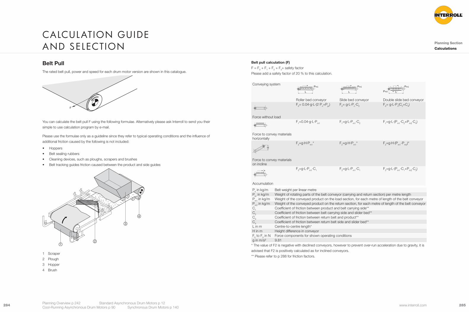
285284 www.interroll.com
Belt pull calculation (F)
F = F0 + F1 + F2 + F3+ safety factor
Please add a safety factor of 20 % to this calculation.
Conveying system
L
Pm1
Roller bed conveyor
L
Pm1
Slide bed conveyor
L
Pm1
Pm2
Double slide bed conveyor
Force without load
F0= 0.04·g·L·(2 Pn+Ppr) F0= g·L·Pn·C2 F0= g·L·Pn(C2+C4)
Force to convey materials horizontally
F1=0.04·g·L·Pm1 F1=g·L·Pm1·C2 F1=g·L·(Pm1·C2+Pm2·C4)
H
Force to convey materials on incline
F2=g·H·Pm1* F2=g·H·Pm1* F2=g·H·(Pm1-Pm2)*
Accumulation
F3=g·L·Pm1·C1 F3=g·L·Pm1·C1 F3=g·L·(Pm1·C1+Pm2·C3)
Pn in kg/m Belt weight per linear metrePpr in kg/m Weight of rotating parts of the belt conveyor (carrying and return section) per metre lengthPm1 in kg/m Weight of the conveyed product on the load section, for each metre of length of the belt conveyorPm2 in kg/m Weight of the conveyed product on the return section, for each metre of length of the belt conveyorC1 Coefficient of friction between product and belt carrying side**C2 Coefficient of friction between belt carrying side and slider bed**C3 Coefficient of friction between return belt and product**C4 Coefficient of friction between return belt side and slider bed**L in m Centre-to-centre length*H in m Height difference in conveyorF0 to F3 in N Force components for shown operating conditionsg in m/s² 9.81
* The value of F2 is negative with declined conveyors, however to prevent over-run acceleration due to gravity, it is
advised that F2 is positively calculated as for inclined conveyors.
** Please refer to p 288 for friction factors.
Belt PullThe rated belt pull, power and speed for each drum motor version are shown in this catalogue.
F
You can calculate the belt pull F using the following formulae. Alternatively please ask Interroll to send you their
simple to use calculation program by e-mail.
Please use the formulae only as a guideline since they refer to typical operating conditions and the influence of
additional friction caused by the following is not included:
• Hoppers
• Belt sealing rubbers
• Cleaning devices, such as ploughs, scrapers and brushes
• Belt tracking guides friction caused between the product and side guides
1 Scraper
2 Plough
3 Hopper
4 Brush
CalCulatIon GuIDe anD seleCtIon Planning Section
Calculations
Planning Overview p 242 Standard Asynchronous Drum Motors p 12 Cool-Running Asynchronous Drum Motors p 90 Synchronous Drum Motors p 140
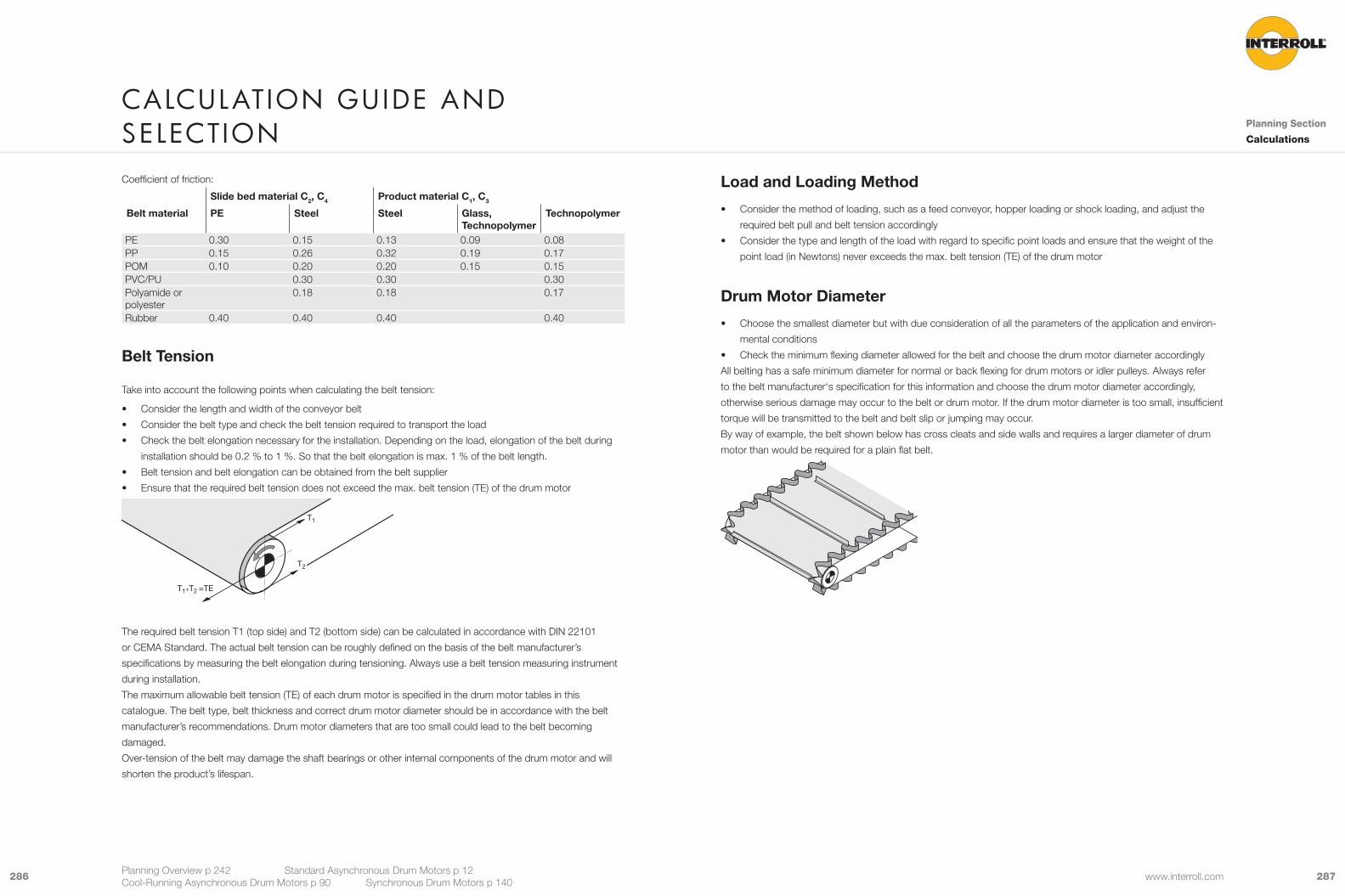
287286 www.interroll.com
Load and Loading Method
• Consider the method of loading, such as a feed conveyor, hopper loading or shock loading, and adjust the
required belt pull and belt tension accordingly
• Consider the type and length of the load with regard to specific point loads and ensure that the weight of the
point load (in Newtons) never exceeds the max. belt tension (TE) of the drum motor
Drum Motor Diameter
• Choose the smallest diameter but with due consideration of all the parameters of the application and environ-
mental conditions
• Check the minimum flexing diameter allowed for the belt and choose the drum motor diameter accordingly
All belting has a safe minimum diameter for normal or back flexing for drum motors or idler pulleys. Always refer
to the belt manufacturer‘s specification for this information and choose the drum motor diameter accordingly,
otherwise serious damage may occur to the belt or drum motor. If the drum motor diameter is too small, insufficient
torque will be transmitted to the belt and belt slip or jumping may occur.
By way of example, the belt shown below has cross cleats and side walls and requires a larger diameter of drum
motor than would be required for a plain flat belt.
Coefficient of friction:
Slide bed material C2, C4 Product material C1, C3
Belt material PE Steel Steel Glass, Technopolymer
Technopolymer
PE 0.30 0.15 0.13 0.09 0.08PP 0.15 0.26 0.32 0.19 0.17POM 0.10 0.20 0.20 0.15 0.15PVC/PU 0.30 0.30 0.30Polyamide or polyester
0.18 0.18 0.17
Rubber 0.40 0.40 0.40 0.40
Belt Tension
Take into account the following points when calculating the belt tension:
• Consider the length and width of the conveyor belt
• Consider the belt type and check the belt tension required to transport the load
• Check the belt elongation necessary for the installation. Depending on the load, elongation of the belt during
installation should be 0.2 % to 1 %. So that the belt elongation is max. 1 % of the belt length.
• Belt tension and belt elongation can be obtained from the belt supplier
• Ensure that the required belt tension does not exceed the max. belt tension (TE) of the drum motor
T1
T2
T1+T2 =TE
The required belt tension T1 (top side) and T2 (bottom side) can be calculated in accordance with DIN 22101
or CEMA Standard. The actual belt tension can be roughly defined on the basis of the belt manufacturer’s
specifications by measuring the belt elongation during tensioning. Always use a belt tension measuring instrument
during installation.
The maximum allowable belt tension (TE) of each drum motor is specified in the drum motor tables in this
catalogue. The belt type, belt thickness and correct drum motor diameter should be in accordance with the belt
manufacturer’s recommendations. Drum motor diameters that are too small could lead to the belt becoming
damaged.
Over-tension of the belt may damage the shaft bearings or other internal components of the drum motor and will
shorten the product’s lifespan.
CalCulatIon GuIDe anD seleCtIon Planning Section
Calculations
Planning Overview p 242 Standard Asynchronous Drum Motors p 12 Cool-Running Asynchronous Drum Motors p 90 Synchronous Drum Motors p 140
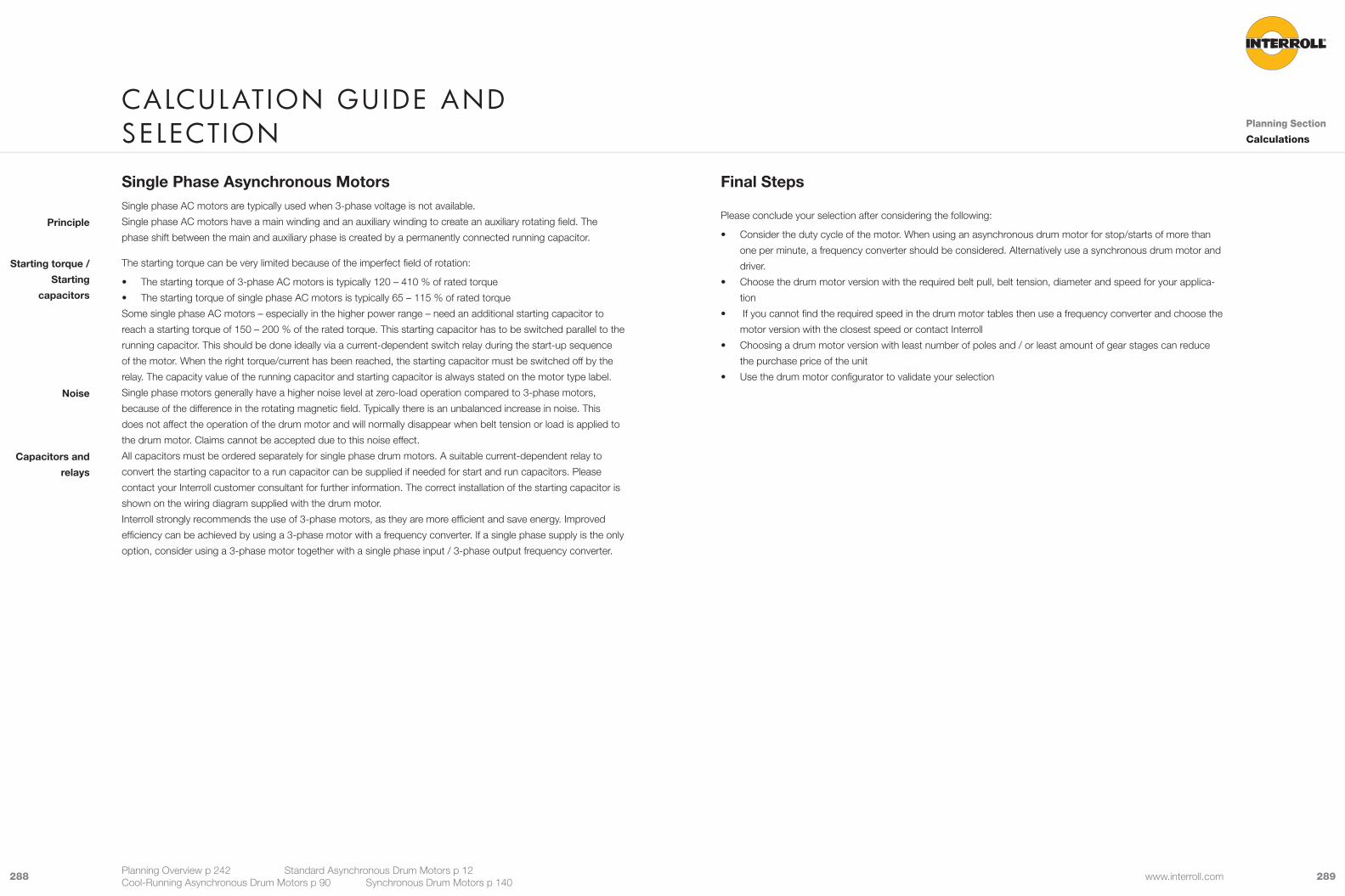
289288 www.interroll.com
Final Steps
Please conclude your selection after considering the following:
• Consider the duty cycle of the motor. When using an asynchronous drum motor for stop/starts of more than
one per minute, a frequency converter should be considered. Alternatively use a synchronous drum motor and
driver.
• Choose the drum motor version with the required belt pull, belt tension, diameter and speed for your applica-
tion
• If you cannot find the required speed in the drum motor tables then use a frequency converter and choose the
motor version with the closest speed or contact Interroll
• Choosing a drum motor version with least number of poles and / or least amount of gear stages can reduce
the purchase price of the unit
• Use the drum motor configurator to validate your selection
Single Phase Asynchronous MotorsSingle phase AC motors are typically used when 3-phase voltage is not available.
Single phase AC motors have a main winding and an auxiliary winding to create an auxiliary rotating field. The
phase shift between the main and auxiliary phase is created by a permanently connected running capacitor.
The starting torque can be very limited because of the imperfect field of rotation:
• The starting torque of 3-phase AC motors is typically 120 – 410 % of rated torque
• The starting torque of single phase AC motors is typically 65 – 115 % of rated torque
Some single phase AC motors – especially in the higher power range – need an additional starting capacitor to
reach a starting torque of 150 – 200 % of the rated torque. This starting capacitor has to be switched parallel to the
running capacitor. This should be done ideally via a current-dependent switch relay during the start-up sequence
of the motor. When the right torque/current has been reached, the starting capacitor must be switched off by the
relay. The capacity value of the running capacitor and starting capacitor is always stated on the motor type label.
Single phase motors generally have a higher noise level at zero-load operation compared to 3-phase motors,
because of the difference in the rotating magnetic field. Typically there is an unbalanced increase in noise. This
does not affect the operation of the drum motor and will normally disappear when belt tension or load is applied to
the drum motor. Claims cannot be accepted due to this noise effect.
All capacitors must be ordered separately for single phase drum motors. A suitable current-dependent relay to
convert the starting capacitor to a run capacitor can be supplied if needed for start and run capacitors. Please
contact your Interroll customer consultant for further information. The correct installation of the starting capacitor is
shown on the wiring diagram supplied with the drum motor.
Interroll strongly recommends the use of 3-phase motors, as they are more efficient and save energy. Improved
efficiency can be achieved by using a 3-phase motor with a frequency converter. If a single phase supply is the only
option, consider using a 3-phase motor together with a single phase input / 3-phase output frequency converter.
Principle
Starting torque /
Starting
capacitors
Noise
Capacitors and
relays
CalCulatIon GuIDe anD seleCtIon Planning Section
Calculations
Planning Overview p 242 Standard Asynchronous Drum Motors p 12 Cool-Running Asynchronous Drum Motors p 90 Synchronous Drum Motors p 140

291290 www.interroll.com
The drum motor output torque available is dependent on the running frequency, please refer to graph.
T/TN
10.90.80.70.60.50.40.30.20.1
0 10 20 30 40 50 60 70 80 90 100 110 120 f / Hz
T Available torque
TN Rated torque
f Frequency
For 50 Hz rated frequency motors, the hyperbolic characteristic of the power equation supersedes to quadratic
when driven with frequencies above 80 Hz (affected by breakdown torque and voltages influences ).
When using the 87 Hz characteristic, please consult Interroll, as this practice generates additional motor power
loss which increases abnormal heating up. This practice should not be applied to 2-poles drum motors.
To reduce EMC emissions, choose a screened cable for the drum motor when installing with a frequency converter.
The use of a frequency converter can control the speed at which the drum motor drives the conveyor. Interroll
frequency converters type IFI-IP55 can be factory pre-set on the basis of the motor data and so guarantee faultfree
operation and a longer service life of the motor components.
• Quick and easy installation
• Wide variable speed range
• Soft but powerful starting and stopping
• Acceleration ramping for smooth handling of loads
• Overheating protection. This is important when using a standard drum motor with no belt, narrow belt width
application or to drive a positive drive belt. Overheating prevention results in a power derating of about 18 %.
• The derated power can be calculated as follows: PN derated = PN x 0.83
• The derated belt pull can be calculated as follows: FN derated = FN x 0.83
• Energy saving by optimisation power usage
• Continuous adjustment of power
• Suitable for positioning when combined with an encoder (Not possible with Interroll IFI-IP55 Inverter)
• Dynamic DC-braking
• With integrated or external EMC filter
• Can replace single phase motors
Choose a frequency converter based on the rated power and rated current of your drum motor and its rated input
voltage (refer to page p 242).
When using a frequency converter and in order to meet local EMC requirements, the drum motor should be
ordered with a screened cable. It is recommended that motor filters are installed at the frequency converter output
in order to reduce reflected wave phenomenon which may generate high voltage peaks on the motor windings.
Interroll motor windings support voltage peaks up to 1,000 V per microsecond.
For Interroll frequency converters IFI-IP55 the maximum motor cable length without filters is 20 m. For other
frequency converter suppliers, this maximum recommended length without filters can be different and must comply
with the supplier‘s recommendations.
Care should be taken with applications using high output frequencies. High frequencies can cause noise, vibration
and resonance and will reduce the nominal motor output torque. Very low frequencies can cause overheating and
motor power losses. This is influenced by the application environment and frequency converter parameter setting.
When selecting a drum motor for very low frequencies, the rated drum motor power should be 20 % higher than
necessary for the application. If in doubt, please refer to Interroll for advice.
Characteristics
Selection
frequenCy Converters for Drum motors
Planning
Section
Frequency
Converters
Planning Overview p 242 Standard Asynchronous Drum Motors p 12 Cool-Running Asynchronous Drum Motors p 90 Synchronous Drum Motors p 140
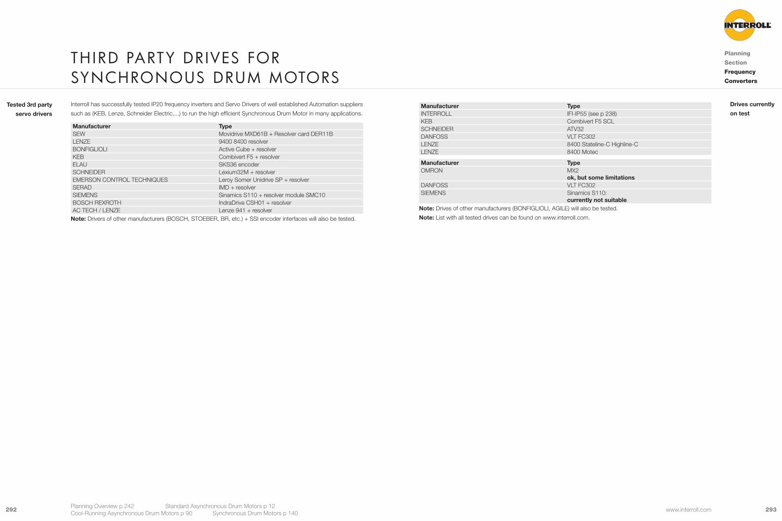
293292 www.interroll.com
Interroll has successfully tested IP20 frequency inverters and Servo Drivers of well established Automation suppliers
such as (KEB, Lenze, Schneider Electric,...) to run the high efficient Synchronous Drum Motor in many applications.
Manufacturer TypeSEW Movidrive MXD61B + Resolver card DER11BLENZE 9400 8400 resolverBONFIGLIOLI Active Cube + resolverKEB Combivert F5 + resolverELAU SKS36 encoderSCHNEIDER Lexium32M + resolverEMERSON CONTROL TECHNIQUES Leroy Somer Unidrive SP + resolverSERAD IMD + resolverSIEMENS Sinamics S110 + resolver module SMC10BOSCH REXROTH IndraDrive CSH01 + resolverAC TECH / LENZE Lenze 941 + resolver
Note: Drivers of other manufacturers (BOSCH, STOEBER, BR, etc.) + SSI encoder interfaces will also be tested.
Tested 3rd party
servo drivers
th IrD party DrIves for synChronous Drum motors
Planning
Section
Frequency
Converters
Planning Overview p 242 Standard Asynchronous Drum Motors p 12 Cool-Running Asynchronous Drum Motors p 90 Synchronous Drum Motors p 140
Manufacturer TypeINTERROLL IFI-IP55 (see p 238)KEB Combivert F5 SCLSCHNEIDER ATV32DANFOSS VLT FC302LENZE 8400 Stateline-C Highline-CLENZE 8400 Motec
Manufacturer TypeOMRON MX2
ok, but some limitationsDANFOSS VLT FC302SIEMENS Sinamics S110:
currently not suitableNote: Drives of other manufacturers (BONFIGLIOLI, AGILE) will also be tested.
Note: List with all tested drives can be found on www.interroll.com.
Drives currently
on test

295294 www.interroll.com
Thermal ProtectionA thermal winding protection switch is incorporated in all Interroll Drum Motors and consists of a simple reversible
bimetal switch built into the motor winding head. This must be connected externally in such a way that it will switch
off the power to the motor by interrupting a relay device or a current limitation coil of an external motor protection
switch. If a thermal overload occurs in the motor causing the stator winding to overheat, the switch will open at
a pre-determined temperature (standard 130 °C) and interrupt the power supply. If the thermal protector is not
connected, as described above, the warranty will be invalidated. Please contact Interroll if you wish to use other
types of thermal winding protection.
In cases where a frequency converter is used, the thermal protection should be connected to the I/O of the
frequency converter.
For optimal protection the integral thermal winding protection should be combined in a control system with an
additional external thermal protection device.
Fig.: Standard thermal/current overload protection - automatically resetting
Lifetime: 10,000 cyclesAC cos = 1 2.5 A 250 V AC
cos = 0.6 1.6 A 250 V ACDC cos = 1 1.6 A 24 V DC
cos = 0.6 1.25 A 48 V DC
Lifetime: 2,000 cyclesAC cos = 1 6.3 A 250 V ACBack setting temperature 40 K ± 15 KResistance < 50 mΩContact bounce time < 1 ms
Optimum
protection
Asynchronous MotorAll data, excluding the rated voltage, number of poles, number of phases and physical dimensions, is subject to a
tolerance of +10 % and -15 %.
The motors (230 / 400 V / 50 Hz) are designed in accordance with IEC 60034-1 for using within a voltage range of
± 5 % of the rated voltage.
The motor will be supplied coupled for 3-phase / 400 V / 50 Hz connection unless otherwise specified.
All speeds stated in this catalogue are subject to a tolerance of ±10 %. This depends on the temperature, load and
friction factors.
All stator windings are produced in accordance with the International Electronic Commission (IEC) DS 188 IV B1
and VDE 0530.
Asynchronous AC squirrel cage induction motor.
• Drum motors for alternative voltages and frequencies are available on request
• S-series drum motors are normally supplied with one voltage option, either star or delta, but can be offered
with star/delta connection on request
• I-series drum motors are offered with star/delta connection unless fitted with a brake whereby only one voltage
is available
2-speed motors can be provided to give two different output speeds. The ratio of the speeds is 1:2, due to the
number of poles used. Alternatively, Interroll recommends the use of single-speed drum motors with frequency
converters to provide better power optimisation with different speeds, adjustable speed, controlled speed, ramping
or soft starting.
Unless otherwise specified, all motors are supplied as standard for 3-phase / 400 V / 50 Hz supply. Interroll can
offer all standard voltages and standard frequencies for worldwide use.
Synchronous MotorAll data, excluding the rated voltage, number of poles, number of phases and physical dimensions, is subject to a
tolerance of +10 % and -15 %.
All stator windings are produced in accordance with the International Electronic Commission (IEC) DS 188 IV B1
and VDE 0530.
All speeds stated in this catalogue are subject to a tolerance of ±10 %. This depends on the temperature, load and
friction factors.
AC PM Synchronous Motor
200-240 VAC; 380-440 VAC
110 V AC and 48 VDC
Tolerances
Rated voltage
Speed
Motor size
Motor type
Alternative
voltage and
frequeny
2-speed motors
3-phase motors
Tolerances
Speed
Motor type
Power supply
Option
materIal speCIf ICatIon
Planning
Section
Material
Specification
Planning Overview p 242 Standard Asynchronous Drum Motors p 12 Cool-Running Asynchronous Drum Motors p 90 Synchronous Drum Motors p 140

297296 www.interroll.com
Sealing SystemAll internal parts are fully protected by a double-lipped seal (FPM or NBR) fitted in both end housings.
i-series drum motors are fitted with external labyrinth seal and hardened ground sleeves under the shaft seals to
increase performance and lifetime.
S-series drum motors are fitted with external deflection seals made from NBR.
D-series drum motors are fitted with external deflection seals made from PTFE.
Labyrinth seal material Standards Material number Short nameMild steel, zinc-plated EN 10027 1.0037 S235 JRStainless steel EN 10027 1.4301 X5CrNi18-10
Interroll Drum Motors are provided with IP66 protection as standard. IP69k is available for D-Series.
Protection against solid bodies Protection of internal equipment against harmful ingress of waterSymbol IP, first
numberDefinition Symbol IP, second
numberDefinition
5 Dust-protected
4 Protected against spray water
6 Dust-tight 5 Protected against water jets (P1 nozzle 6.3 mm, water delivery rate 12.5 l/min ±5 %)
6 Protected from projections of water similar to marine swells (P2 nozzle 12.5 mm, water delivery rate 100 l/min ±5 %)
.15m -1m7 Ingress of water in quantities causing harmful
effects shall not be possible when the enclosure is temporarily immersed 1 metre in water under standardised conditions of pressure and time.
9k Protected against the effects of high-pressure liquids
• Test with fan nozzle
• Test unit on turntable ( 5revolutions /
minute
• Spray quantity 14 to 16 l/min
• Water pressure about 8,000 to 10,000
kPa at 80 ±5 °C with a duration of 30 s
per position
• Water aimed at the housing with incre-
ased pressure from each direction must
not have any damaging effect.
i-Series
S-Series
D-Series
Protection rate
Shell Manufactured from thick-walled mild steel tube and machine crowned to ensure correct belt tracking. Alternatively,
the tube can be made of stainless steel (AISI 304). The stainless steel version has extended chemical resistance
and is suitable for food applications.
Shells with special crowns and grooves are used for multiple belt conveyors.
Material Standards Material number Short nameMild steel EN 10027 1.0037 S235 JRStainless steel EN 10027 1.4301 X5CrNi18-10
Surface roughnessThe shells of Interroll D- and i-series motors are normally supplied with standard roughness, but also the following
versions can be supplied:
• Standard roughness: Rz 15-20 µm (Ra 4-5 µm)
• Fine turned roughness: < Rz 6.3 µm (Ra 1.4 µm)
• Electro polished: < Rz 1.6 µm (Ra 0.8 µm)
End Housing Interroll Drum Motors are supplied with pressed and glued end housings. End housings are manufactured from sea
water-resistant aluminium but can also be supplied in stainless steel.
Interroll offers the following versions of end housings:
• Standard
• With V-grooves
• With O-grooves
• With chain sprockets
Material Standards Material number Short nameMild steel EN 10027 1.0037 S235 JR Stainless steel EN 10027 1.4305 X8CrNiS18-9Aluminium EN 10027 3.2385 D-AlSi10Mg
ShaftFront and rear shafts are manufactured from mild steel or, optionally, stainless steel (AISI 304) and have identical
shaft diameters and shaft flats at both ends.
Interroll offers the following versions of shafts:
• Standard
• Cross-drilled thread
Material Standards Material number Short nameMild steel EN 10027 1.0037 S235 JRStainless steel EN 10027 1.4305 X8CrNiS18-9
materIal speCIf ICatIon
Planning
Section
Material
Specification
Planning Overview p 242 Standard Asynchronous Drum Motors p 12 Cool-Running Asynchronous Drum Motors p 90 Synchronous Drum Motors p 140
External
labyrinths

299298 www.interroll.com
Electrical Connectors Material specification for terminal boxes and straight and elbow connectors.
The motor is connected through a hollow shaft to a terminal box or cable connector with at least 1 m of external
cable. Straight and elbow cable connectors are available.
In conditions where there are varying ambient temperatures of between e.g. -5 to +40 °C, condensation may form
inside the terminal box. In conditions such as these, it is advisable to use cables with straight or elbow connectors.
Straight and elbow connectors
Material Standards Material number Short nameStainless steel EN 10027 1.4305 X8CrNiS18-9Brass/Nickel EN 10027 2.0401 CuZn39Pb3 Technopolymer ISO 1043 SK605 NC10 Crastin Polybutylenterephthalat
Terminal box
Material Standards Material number Short nameStainless steel EN 10027 1.4305 X8CrNiS18-9Aluminium EN 10027 3.2385 CuZn39Pb3 Technopolymer ISO 1874 PA 6, MHR, 14-090, GF30 Grilon BG-30 S
Shell LaggingThis type of synthetic rubber has good wear characteristics, excellent resistance to oil, fuel, and other chemicals
and is also easy to clean. Its resilience makes NBR the perfect material for the rubber lagging of drum shells. It
can be used in most material handling applications. NBR withstands temperatures from -40 to +120 °C, Nitrile
rubber is generally resistant to aliphatic hydrocarbons but, like natural rubber, can be attacked by ozone, aromatic
hydrocarbons, ketones, esters and aldehydes. White NBR is accepted for the food processing industry and is
offered with FDA and EC1935/2004 approval.
PU represents any polymer consisting of a chain of organic units joined by urethane (carbonate) links. It is tear-
resistant and is superior to rubber. Polyurethane has outstanding resistance to oxygen, ozone, sunlight and
general weather conditions. Most formulations offer an extremely long lifespan, good resistance to heat and cold at
temperatures of between -35 and +80 °C and is offered with EC1935/2004 approval.
Note: Minimum PU thickness 4 mm, maximum shell length (SL) 1,200 mm.
Hot vulcanised NBR rubber lagging can be used to increase friction between the drum motor and belt for high
torque applications and to reduce belt slip. Alternatively it can be profiled to drive modular belts and other special
applications. Due to the high temperature of the process, the lagging must be applied to the shell before the
drum motors are assembled. The result is a very strong bonded rubber, suitable for high torque applications
and completely sealed to the shell. This method has long-life characteristics and is recommended for hygienic
applications.
Note: NBR profiled lagging is not recommended to drive PU thermal belts due to the high friction which can cause
the belt to jump.
Condensation in
terminal box
NBR
PU
Hot
vulcanisation
materIal speCIf ICatIon
Planning
Section
Material
Specification
Planning Overview p 242 Standard Asynchronous Drum Motors p 12 Cool-Running Asynchronous Drum Motors p 90 Synchronous Drum Motors p 140
Cold vulcanised NBR rubber lagging is used to increase the friction between the drum and belt in order to reduce
belt slip. The cold process requires a special adhesive (cement) to glue the lagging onto the drum shell. It has
a shorter lifespan than hot vulcanisation when used in high torque applications. Cold vulcanised white NBR
material is FDA approved but is not ideal for food or hygienic applications, due to the glue and lagging joint that
could harbour bacteria. The lagging follows the original shape of the drum shell (crowned or cylindrical) and is
not machined afterwards. However, the process can be applied quickly to finished assembled drum motors and
therefore is a quick and easy solution.
PU material is moulded or cast using a 2-part chemical process to produce lagging for the drum shells or
sprockets to drive modular belts. The PU moulded shell or sprocket is then placed in an oven to stabilise the
chemical reaction and obtain the final mechanical characteristics and hardness required. This process must be
applied to the shell before the drum motor is assembled. Moulded PU lagging can be offered with low friction
suitable for driving positive drive solid homogeneous belts.
Approvals and CertificationsInterroll Drum Motors can be offered certified and approved to UL 1004 for the North American market and cUL for
the Canadian market.
NSF Certification is available on request only. All drum motors can be supplied with CSA (Canadian Standard
Association) specification. If requested, a certificate of approval can be supplied with each drum motor at extra
cost.
Interroll Drum Motors for food industry comply to EHEDG and materials comply with FDA, EC1935/2004 and
Ecolab. Cleaning specialist Ecolab has certified a 5-year minimum lifetime of materials used for the Interroll Drum
Motors of the S-series, i-series and D-series when exposed to typical cleaning and disinfecting procedures using
Ecolab‘s Topax range of products: P3-topax 19, P3-topax 686, P3-topax 56 and P3-topactive DES.
Fig.: Ecolab and the Ecolab logo are registered trademarks
of Ecolab Inc. and its affiliated companies
Cold
vulcanisation
PU moulding

301300 www.interroll.com
A choice of straight and elbow connectors for the following cables (including optional terminal boxes) are shown in
each of the product pages, which cover most standard applications.
Choose a screened cable when connecting to a frequency converter to reduce EMC emissions.
Cables for S-series
PUR or external screened cables may not be suitable for some food processing installations. For such applications
an optional blue cable protection cover can be ordered. The cover provides protection against UV light and
cleaning agents. When ordering the external blue cover please chose a cable gland from the product pages.
Reference number 1000583 1000584 1000595 1000569 1000577Main core (quantity) 9 6 6 7 6Cross section mm² 0.75 0.75 0.75 0.75 0.75Numeric codeor colour code
numeric code + colour code
colour code colour code numeric code + colour code
colour code
Insulation conductors (main core) PVC PVC PP PVC PPHalogen-free no no yes no yesData core (quantity) – – – – –Cross section mm² – – – – –Numeric codeorcolour code
– – – – –
Insulation conductors (data core) – – – – –Halogen-free – – – – –Insulation outer sheath PVC PVC PUR PVC PURHalogen- free no no yes no yesColour of outer sheath black black grey black greyScreened (copper / steel) – – – – copperOutside diameter mm 7.30 7.15 7.15 7.15 7.15Operating voltageV
460/800 460/800 450/750 300/500 460/800
Operating voltage acc. to ULV
300/500 300/500 340/600 300/500 300/500
Temperature range °C -40 to +105-40 to +80 (UL)
-40 to +105-40 to +80 (UL)
-40 to +90-40 to +80 (UL)
-40 to +105-40 to +80 (UL)
-40 to +105-40 to +80 (UL)
Approval cULus cULus cULus cULus cULus
S-seriesA choice of straight and elbow connectors for the following cables (including optional terminal boxes) are shown in
each of the product pages, which cover most standard applications.
For D-series only screened cables are available.
Choose a screened cable when connecting to a frequency converter to reduce EMC emissions.
Cables for i- and D- series
Reference number
1002056 1002057 1002058 1002059 1002060* 1002061 1002062 1004272*
Main core (quantity)
7 7 7 7 4 7 7 4
Cross section mm²
0.75 0.75 0.75 0.75 0.75 0.50 0.50 0.50
Numeric codeorcolour code
numeric code
numeric code
numeric code
numeric code
numeric code
numeric code
numeric code
numeric code
Insulation conductors (main core)
PVC PVC PP PP ETFE ETFE ETFE ETFE
Halogen-free no no yes yes no no no yesData core (quantity)
2 2 2 2 2 2 2 2
Cross section mm²
0.34 0.34 0.34 0.34 0.34 0.34 0.34 0.34
Numeric codeorcolour code
colour code
colour code
colour code
colour code
colour code
colour code
colour code
colour code
Insulation conductors (data core)
PVC PVC PP PP ETFE ETFE ETFE ETFE
Halogen-free no no yes yes no no no yesInsulation outer sheath
PVC PVC PUR PUR PVC PVC PVC PUR
Halogen- free
no no yes yes no no no yes
Colour outer sheath
black orange black orange orange black orange orange
Screened (copper / steel)
– copper – copper copper – copper copper
Outside diameter mm
9.20 ±0.3 9.98 ±0.3 9.20 ±0.3 9.80 ±0.3 7.10 ±0.3 6.80 ±0.3 7.60 ±0.3 7.80 ±0.2
Operating voltage300 / 600 V
600 600 600 600 600 600 600 600
Temperature range °C
-20 to +105 acc. UL
-20 to +105 acc. UL
-20 to +80 acc. UL
-20 to +80 acc. UL
-20 to +105 acc. UL
-20 to +105 acc. UL
-20 to +105 acc. UL
-20 to +80 acc. UL
Approval cULus cULus cULus cULus cULus* For i- and D- Series
i- and D-series
CablesMaterial
Specification
Cables
Planning Overview p 242 Standard Asynchronous Drum Motors p 12 Cool-Running Asynchronous Drum Motors p 90 Synchronous Drum Motors p 140
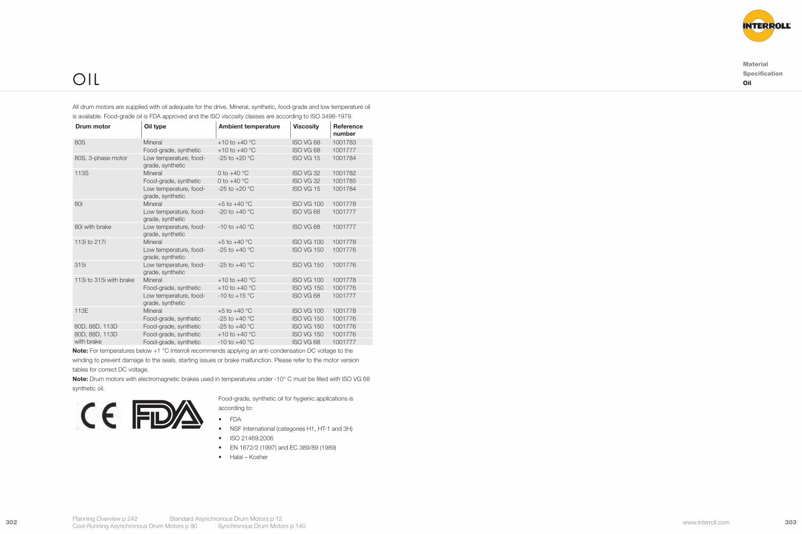
303302 www.interroll.com
All drum motors are supplied with oil adequate for the drive. Mineral, synthetic, food-grade and low temperature oil
is available. Food-grade oil is FDA approved and the ISO viscosity classes are according to ISO 3498-1979.
Drum motor Oil type Ambient temperature Viscosity Reference number
80S Mineral +10 to +40 °C ISO VG 68 1001783Food-grade, synthetic +10 to +40 °C ISO VG 68 1001777
80S, 3-phase motor Low temperature, food-grade, synthetic
-25 to +20 °C ISO VG 15 1001784
113S Mineral 0 to +40 °C ISO VG 32 1001782Food-grade, synthetic 0 to +40 °C ISO VG 32 1001785Low temperature, food-grade, synthetic
-25 to +20 °C ISO VG 15 1001784
80i Mineral +5 to +40 °C ISO VG 100 1001778Low temperature, food-grade, synthetic
-20 to +40 °C ISO VG 68 1001777
80i with brake Low temperature, food-grade, synthetic
-10 to +40 °C ISO VG 68 1001777
113i to 217i Mineral +5 to +40 °C ISO VG 100 1001778Low temperature, food-grade, synthetic
-25 to +40 °C ISO VG 150 1001776
315i Low temperature, food-grade, synthetic
-25 to +40 °C ISO VG 150 1001776
113i to 315i with brake Mineral +10 to +40 °C ISO VG 100 1001778Food-grade, synthetic +10 to +40 °C ISO VG 150 1001776Low temperature, food-grade, synthetic
-10 to +15 °C ISO VG 68 1001777
113E Mineral +5 to +40 °C ISO VG 100 1001778Food-grade, synthetic -25 to +40 °C ISO VG 150 1001776
80D, 88D, 113D Food-grade, synthetic -25 to +40 °C ISO VG 150 100177680D, 88D, 113D with brake
Food-grade, synthetic +10 to +40 °C ISO VG 150 1001776Food-grade, synthetic -10 to +40 °C ISO VG 68 1001777
Note: For temperatures below +1 °C Interroll recommends applying an anti-condensation DC voltage to the
winding to prevent damage to the seals, starting issues or brake malfunction. Please refer to the motor version
tables for correct DC voltage.
Note: Drum motors with electromagnetic brakes used in temperatures under -10° C must be filled with ISO VG 68
synthetic oil.
Food-grade, synthetic oil for hygienic applications is
according to:
• FDA
• NSF International (categories H1, HT-1 and 3H)
• ISO 21469:2006
• EN 1672/2 (1997) and EC 389/89 (1989)
• Halal – Kosher
oIlMaterial
Specification
Oil
Planning Overview p 242 Standard Asynchronous Drum Motors p 12 Cool-Running Asynchronous Drum Motors p 90 Synchronous Drum Motors p 140

305304 www.interroll.com
E33E32
Fig.: 3-phase operation, 6 lead cable, winding for 1 voltage, delta or star connection (internally connected)
Delta connection: Low voltage; Star connection: High voltage
E31E30
Fig.: 3-phase operation, 7 lead cable, winding for 1 voltage, delta or star connection (internally connected)
Delta connection: Low voltage; Star connection: High voltage
Fig.: 3-phase operation, 9 lead cable, winding for 2 voltages, delta or star connection
Delta connection: Low voltage; Star connection: High voltage
Explanation of abbreviations:TC: Thermal control FC: Frequency Converter Tr: Transformation ratioCr: Capacitor run BR: Brake Option 3~: 3-phase motorCs: Capacitor start NC: not connected 1~: 1-phase motorrd: red gy: grey wh: whiteye: yellow gn: green or: orangebu: blue bn: brown vi: violetbk: black pk: pink ( ): alternative colour
Note: The rotational direction of the drum motor is shown on the connection diagrams. The rotation indicated is
correct when looking at the drum motor from the connection side.
Connection Diagrams for Interroll Drum Motors 80S, 113SE12 E12
Fig.: 1-phase operation, 6 lead cable
E10E10
Fig.: 1-phase operation, 7 lead cable
Abbreviations
Rotation
Cable
connections
ConneCtIon D IaGrams
Planning
Section
Connection
Diagrams
Planning Overview p 242 Standard Asynchronous Drum Motors p 12 Cool-Running Asynchronous Drum Motors p 90 Synchronous Drum Motors p 140

307306 www.interroll.com
Connection Diagrams for Interroll Drum Motors 80i, 113i, 138i, 165i, 216i, 217i, 315i
10 10
Fig.: 1-phase operation, 7+2 lead cable
10B 10B
Fig.: 1-phase operation, 7+2 lead cable, with brake
Cable
connectionsE21E20
Fig.: 1-phase operation, 7 lead cable
E45E44
Fig.: 3-phase operation, 9 lead cable, winding for 2 voltages, delta or star connection
Delta connection: Low voltage; Star connection: High voltage
Terminal box
ConneCtIon D IaGrams
Planning
Section
Connection
Diagrams
Planning Overview p 242 Standard Asynchronous Drum Motors p 12 Cool-Running Asynchronous Drum Motors p 90 Synchronous Drum Motors p 140

309308 www.interroll.com
34 34
Fig.: 3-phase operation, 7+2 lead cable, winding for 2 voltages, delta or star connection
Delta connection: Low voltage; Star connection: High voltage
Fig.: 3-phase operation, 7+2 lead cable, 2 speeds, delta or double star connection
Delta connection: Low speed; Double star connection: High speed
Wires 4, 5 and 6 must be isolated single.
30 31
Fig.: 3-phase operation, 4+2 lead cable, winding for 1 voltage, delta or star connection (internally connected)
Delta connection: Low voltage; Star connection: High voltage
30B 31B
Fig.: 3-phase operation, 7+2 lead cable, winding for 1 voltage, delta or star connection
(internally connected), with brake
Delta connection: Low voltage; Star connection: High voltage
ConneCtIon D IaGrams
Planning
Section
Connection
Diagrams
Planning Overview p 242 Standard Asynchronous Drum Motors p 12 Cool-Running Asynchronous Drum Motors p 90 Synchronous Drum Motors p 140

311310 www.interroll.com
20 20
Fig.: 1-phase operation
20B 20B
Fig.: 1-phase operation, with brake
Terminal box
Fig.: 3-phase operation, winding for 1 voltage, star or double star connection (internally connected)
Double star connection: Low voltage; Star connection: High voltage
Fig.: 3-phase operation, winding for 1 voltage, star or double star connection, with brake
(internally connected)
Double star connection: Low voltage; Star connection: High voltage
Fig.: 3-phase operation, winding for 2 voltages, star or double star connection
Double star connection: Low voltage; Star connection: High voltage
ConneCtIon D IaGrams
Planning
Section
Connection
Diagrams
Planning Overview p 242 Standard Asynchronous Drum Motors p 12 Cool-Running Asynchronous Drum Motors p 90 Synchronous Drum Motors p 140
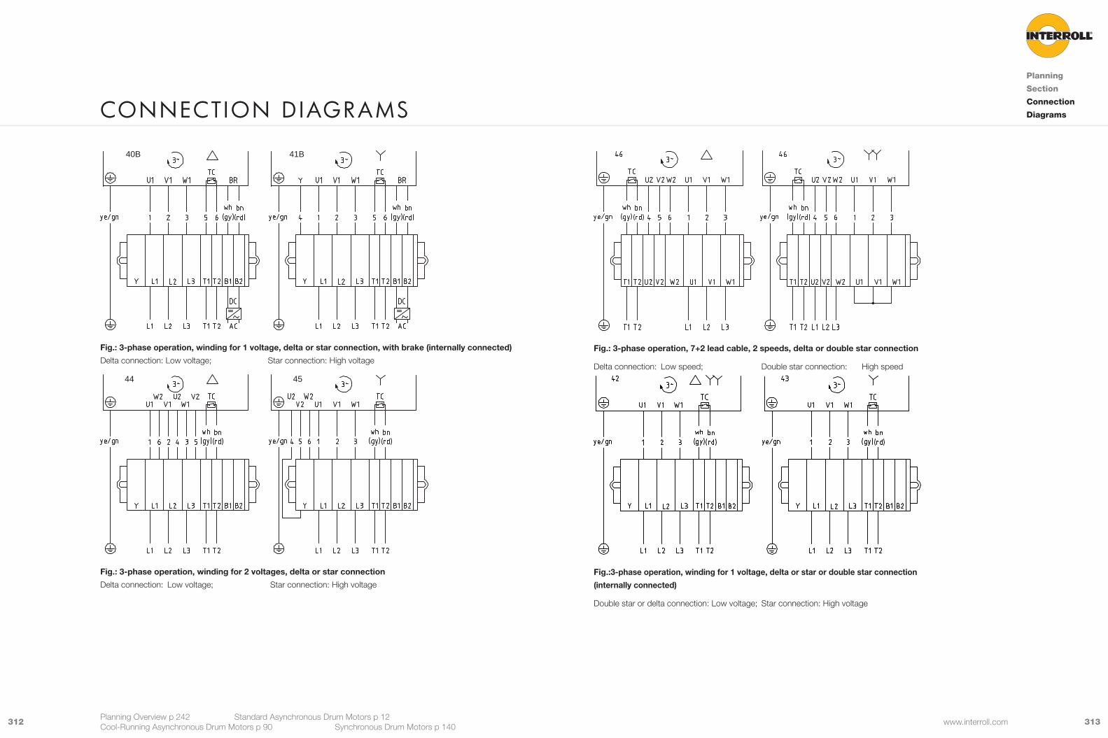
313312 www.interroll.com
Fig.: 3-phase operation, 7+2 lead cable, 2 speeds, delta or double star connection
Delta connection: Low speed; Double star connection: High speed
Fig.:3-phase operation, winding for 1 voltage, delta or star or double star connection
(internally connected)
Double star or delta connection: Low voltage; Star connection: High voltage
40B 41B
Fig.: 3-phase operation, winding for 1 voltage, delta or star connection, with brake (internally connected)
Delta connection: Low voltage; Star connection: High voltage
44 45
Fig.: 3-phase operation, winding for 2 voltages, delta or star connection
Delta connection: Low voltage; Star connection: High voltage
ConneCtIon D IaGrams
Planning
Section
Connection
Diagrams
Planning Overview p 242 Standard Asynchronous Drum Motors p 12 Cool-Running Asynchronous Drum Motors p 90 Synchronous Drum Motors p 140
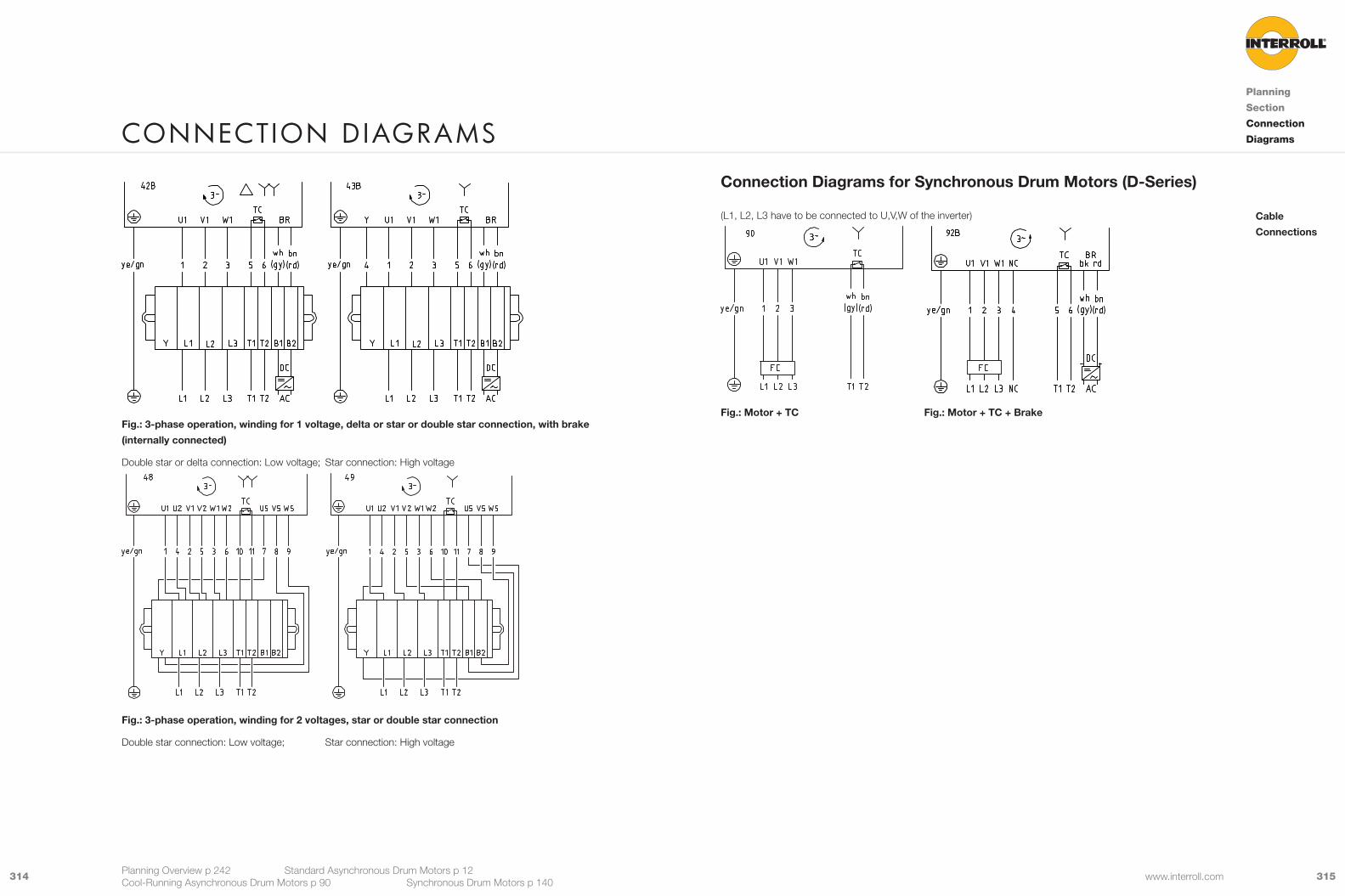
315314 www.interroll.com
Connection Diagrams for Synchronous Drum Motors (D-Series)
(L1, L2, L3 have to be connected to U,V,W of the inverter)
Fig.: Motor + TC Fig.: Motor + TC + Brake
Cable
Connections
ConneCtIon D IaGrams
Planning
Section
Connection
Diagrams
Planning Overview p 242 Standard Asynchronous Drum Motors p 12 Cool-Running Asynchronous Drum Motors p 90 Synchronous Drum Motors p 140
Fig.: 3-phase operation, winding for 1 voltage, delta or star or double star connection, with brake
(internally connected)
Double star or delta connection: Low voltage; Star connection: High voltage
Fig.: 3-phase operation, winding for 2 voltages, star or double star connection
Double star connection: Low voltage; Star connection: High voltage
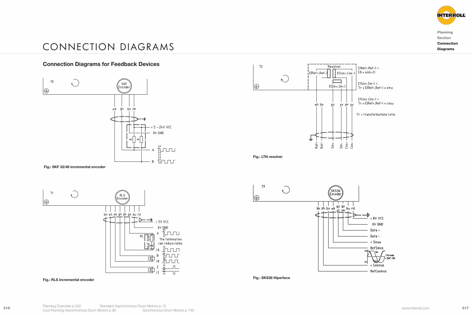
317316 www.interroll.com
ConneCtIon D IaGrams
Planning
Section
Connection
Diagrams
Planning Overview p 242 Standard Asynchronous Drum Motors p 12 Cool-Running Asynchronous Drum Motors p 90 Synchronous Drum Motors p 140
Connection Diagrams for Feedback Devices
Fig.: SKF 32/48 incremental encoder
Fig.: RLS incremental encoder
ϕ
ϕ
ω
Fig.: LTN resolver
Fig.: SKS36 Hiperface

Drive PulleysDrive pulley without bearing Series 7000 see p 228
Quantity, ref. no.: ___, __________________ RL: _______Drive pulley with bearing Series 7000 see p 230
Quantity, ref. no.: ___, __________________ RL: _______
Conveyor RollersConveyor Roller Series 1450 see p 232
Quantity, ref. no.: ___, __________________ RL: _______Universal Conveyor Roller Series 1700 see p 234
Quantity, ref. no.: ___, __________________ RL: _______
IFI – IP55 Frequency inverter for S, i and D-Series Motors
Mounting BracketsAnti-vibration brackets see p 20280S, 113S only Quantity, ref. no.: ___, __________________
Quantity, ref. no.: ___, __________________Light-duty flanged bracket for drum motor see p 20480S, 113S only Quantity, ref. no.: ___, __________________
Quantity, ref. no.: ___, __________________Light-duty flanged bracket for idler pulley see p 20680S, 113S only Quantity, ref. no.: ___, __________________
Quantity, ref. no.: ___, __________________Heavy-duty flanged bracket, Aluminium see p 20880i, 113i, 138i, 165i drum motors and idler pulleys Quantity, ref. no.: ___, __________________
Quantity, ref. no.: ___, __________________Heavy-duty flanged bracket, PE see p 21280i, 113i, 138i, 165i drum motors and idler pulleys Quantity, ref. no.: ___, __________________
Quantity, ref. no.: ___, __________________Plummer block for i-series drum motors and idler see p 21680i, 113i, 138i, 165i, 216i, 217i, 315i drum motors and idler pulleys Quantity, ref. no.: ___, __________________
Quantity, ref. no.: ___, __________________Plummer block for D-series drum motors and idler see p 21680D,88D,113D drum motors and idler pulleys Quantity, ref. no.: ___, __________________
Quantity, ref. no.: ___, __________________
Idler Pulleys for S- and i-seriesIdler pulley with integral bearing see p 218Quantity _______Shell lagging m Same as drum motor m NoneShell m Crowned m Cylindrical m Cylindrical with key
m Special crowns and groovesm Mild steel m Stainless steel
End housing m With V-grooves m With O-grooves m With chain sprocketsm Aluminium m Stainless steel
Shaft m Mild steel m Stainless steel m Cross-drilled threadShaft cap S-series m Aluminium m With cable protection m Regreasable, stainless steelExternal seal i-series m Mild steel, galvanised labyrinth m Stainless steel labyrinth m Stainless steel labyrinth with FPM
Idler pulley without bearings Series 7000 see p 224Quantity, ref. no.: ___, __________________ RL: _______
Idler pulley with bearings Series 7000 see p 226Quantity, ref. no.: ___, __________________ RL: _______
Idler Pulleys for D-SeriesIdler Pulley with integral bearing see p 218Quantity _______Shell lagging m Same as drum motor m NoneShell m Crowned m Cylindrical m Cylindrical with key m Hexagonal 88
m Special crowns and groovesm Mild steel m Stainless steel
End housing m Stainless steelShaft m Stainless steelExternal seal m Deflection seal m PTFE
ConfIGurator aCCessorIes
IFI – IP55 Frequency Inverter see p 238Quantity
Model m PD – A – 400 – 1A5 – 55 (380 - 480 V ±10 % 3 Phase) __________m PD – A – 230 – 2A5 – 55 (200 - 240 V ±10 % 1 Phase) __________
Accessories m OptiPort + RJ 45 cable __________m OptiStick __________m OptiTools Software __________m USB to RS485 adapter __________m M23 motor connector 8 pole male __________m M23 power connector 6 pole female __________m Power cable 400 V + M23 plug 6 pole female __________m Power cable 230 V + M23 plug 6 pole female __________
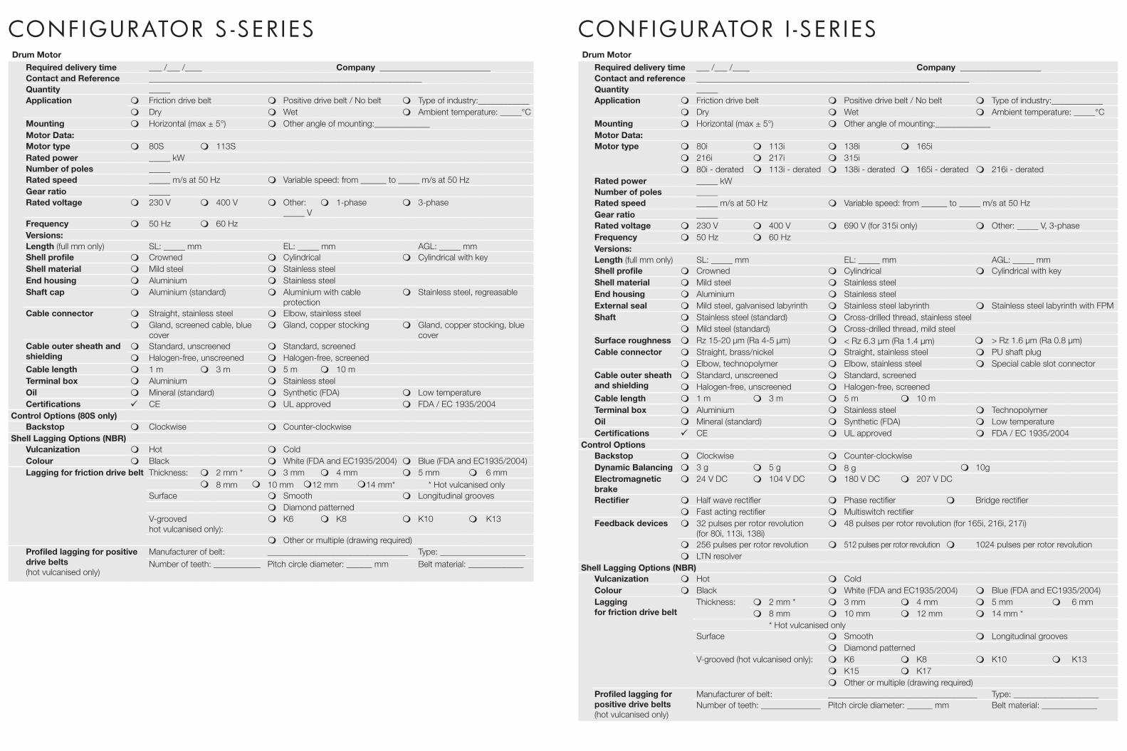
ConfIGurator s -ser IesDrum Motor
Required delivery time ___ /___ /____ Company __________________________Contact and Reference ________________________________________________________________Quantity _____Application m Friction drive belt m Positive drive belt / No belt m Type of industry:____________
m Dry m Wet m Ambient temperature: _____°CMounting m Horizontal (max ± 5°) m Other angle of mounting:_____________Motor Data:Motor type m 80S m 113SRated power _____ kWNumber of poles _____Rated speed _____ m/s at 50 Hz m Variable speed: from ______ to _____ m/s at 50 HzGear ratio _____Rated voltage m 230 V m 400 V m Other:
_____ Vm 1-phase m 3-phase
Frequency m 50 Hz m 60 HzVersions:Length (full mm only) SL: _____ mm EL: _____ mm AGL: _____ mmShell profile m Crowned m Cylindrical m Cylindrical with keyShell material m Mild steel m Stainless steelEnd housing m Aluminium m Stainless steelShaft cap m Aluminium (standard) m Aluminium with cable
protectionm Stainless steel, regreasable
Cable connector m Straight, stainless steel m Elbow, stainless steelm Gland, screened cable, blue
coverm Gland, copper stocking m Gland, copper stocking, blue
coverCable outer sheath and shielding
m Standard, unscreened m Standard, screenedm Halogen-free, unscreened m Halogen-free, screened
Cable length m 1 m m 3 m m 5 m m 10 mTerminal box m Aluminium m Stainless steelOil m Mineral (standard) m Synthetic (FDA) m Low temperatureCertifications 9 CE m UL approved m FDA / EC 1935/2004
Control Options (80S only)Backstop m Clockwise m Counter-clockwise
Shell Lagging Options (NBR)Vulcanization m Hot m ColdColour m Black m White (FDA and EC1935/2004) m Blue (FDA and EC1935/2004)Lagging for friction drive belt Thickness: m 2 mm * m 3 mm m 4 mm m 5 mm m 6 mm
m 8 mm m 10 mm m12 mm m14 mm* * Hot vulcanised onlySurface m Smooth m Longitudinal grooves
m Diamond patternedV-grooved hot vulcanised only):
m K6 m K8 m K10 m K13
m Other or multiple (drawing required)Profiled lagging for positive drive belts (hot vulcanised only)
Manufacturer of belt: _________________________________ Type: ____________________Number of teeth: ___________ Pitch circle diameter: ______ mm Belt material: _____________
Drum MotorRequired delivery time ___ /___ /____ Company ___________________Contact and reference ________________________________________________________________Quantity _____Application m Friction drive belt m Positive drive belt / No belt m Type of industry:____________
m Dry m Wet m Ambient temperature: _____°CMounting m Horizontal (max ± 5°) m Other angle of mounting:_____________Motor Data:Motor type m 80i m 113i m 138i m 165i
m 216i m 217i m 315im 80i - derated m 113i - derated m 138i - derated m 165i - derated m 216i - derated
Rated power _____ kWNumber of poles _____Rated speed _____ m/s at 50 Hz m Variable speed: from ______ to _____ m/s at 50 HzGear ratio _____Rated voltage m 230 V m 400 V m 690 V (for 315i only) m Other: _____ V, 3-phaseFrequency m 50 Hz m 60 HzVersions:Length (full mm only) SL: _____ mm EL: _____ mm AGL: _____ mmShell profile m Crowned m Cylindrical m Cylindrical with keyShell material m Mild steel m Stainless steelEnd housing m Aluminium m Stainless steelExternal seal m Mild steel, galvanised labyrinth m Stainless steel labyrinth m Stainless steel labyrinth with FPMShaft m Stainless steel (standard) m Cross-drilled thread, stainless steel
m Mild steel (standard) m Cross-drilled thread, mild steelSurface roughness m Rz 15-20 µm (Ra 4-5 µm) m < Rz 6.3 µm (Ra 1.4 µm) m > Rz 1.6 µm (Ra 0.8 µm)Cable connector m Straight, brass/nickel m Straight, stainless steel m PU shaft plug
m Elbow, technopolymer m Elbow, stainless steel m Special cable slot connectorCable outer sheath and shielding
m Standard, unscreened m Standard, screenedm Halogen-free, unscreened m Halogen-free, screened
Cable length m 1 m m 3 m m 5 m m 10 mTerminal box m Aluminium m Stainless steel m TechnopolymerOil m Mineral (standard) m Synthetic (FDA) m Low temperatureCertifications 9 CE m UL approved m FDA / EC 1935/2004
Control OptionsBackstop m Clockwise m Counter-clockwiseDynamic Balancing m 3 g m 5 g m 8 g m 10gElectromagnetic brake
m 24 V DC m 104 V DC m 180 V DC m 207 V DC
Rectifier m Half wave rectifier m Phase rectifier m Bridge rectifierm Fast acting rectifier m Multiswitch rectifier
Feedback devices m 32 pulses per rotor revolution (for 80i, 113i, 138i)
m 48 pulses per rotor revolution (for 165i, 216i, 217i)
m 256 pulses per rotor revolution m 512 pulses per rotor revolution m 1024 pulses per rotor revolutionm LTN resolver
Shell Lagging Options (NBR)Vulcanization m Hot m ColdColour m Black m White (FDA and EC1935/2004) m Blue (FDA and EC1935/2004)Lagging for friction drive belt
Thickness: m 2 mm * m 3 mm m 4 mm m 5 mm m 6 mmm 8 mm m 10 mm m 12 mm m 14 mm *
* Hot vulcanised onlySurface m Smooth m Longitudinal grooves
m Diamond patternedV-grooved (hot vulcanised only): m K6 m K8 m K10 m K13
m K15 m K17m Other or multiple (drawing required)
Profiled lagging for positive drive belts (hot vulcanised only)
Manufacturer of belt: ___________________________________ Type: ____________________Number of teeth: ______________ Pitch circle diameter: ______ mm Belt material: _____________
ConfIGurator I -ser Ies

Drum MotorRequired delivery time ___ /___ /____ Company ___________________Contact and reference ________________________________________________________________Quantity _____Application m Friction drive belt m Positive drive belt / No belt m Type of industry:____________
m Dry m Wet m Ambient temperature: _____°CMounting m Horizontal (max ± 5°) m Other angle of mounting:_____________Motor Data:Motor type m 80D m 88D m 113DRated power _____ kWNumber of poles _____Rated speed _____ m/s at 50 Hz m Variable speed: from ______ to _____ m/s at 50 HzGear ratio _____Rated voltage m 200-240V
3 phasem 300-440V
3 phasem 48 V DC m Other: _____ V,
3-phaseFrequency m 50 Hz m 60 HzVersions:Length (full mm only) SL: _____ mm EL: _____ mm AGL: _____ mmShell profile m Crowned m Cylindrical m Cylindrical
with keym Hexagonal
Shell material m Mild steel m Stainless steelEnd housing m Stainless steelExternal seal m Deflection seal PTFEShaft m Stainless steel Surface roughness m Rz 15-20 µm (Ra 4-5 µm) m < Rz 6.3 µm (Ra 1.4 µm) m > Rz 1.6 µm (Ra 0.8 µm)Cable connector m Straight, brass/nickel m Straight, stainless steel IP69K
EHEDGm Elbow, technopolymer
m Elbow, stainless steel m Straight cable nipple m Straight cable connector for feedback device
m Elbow connector stainless steel for feedback device
m Feedback device has 2 cables
Cable m Standard, screened m Halogen-free, screenedCable length m 1.5 m m 2 m* m 3 m m 5 m m 7.5 m m 10 m m 20 m
*Max cable length for IFI- IP55 InverterOil m Synthetic (FDA) m Low temperatureCertifications 9 CE m cULus approved m FDA / EC 1935/2004
Control OptionsSafety holding brake m 24 V DC m 205 V DCRectifier m 230 V AC in / 24 V DC out m 230 V AC in / 205 V DC outFeedback devices m RLS incremental encoder m LTN Resolver m SKS 36 Hiperface
Shell Lagging Options (NBR)Vulcanization m HotColour m Black m White (FDA and EC1935/2004) m Blue (FDA and EC1935/2004)Lagging for friction drive belt
Thickness: m 2 mm * m 3 mm m 4 mm m 5 mm m 6 mmm 8 mm m 10 mm m 12 mm m 14 mm * *Hot vulcanised only
Surface m Smooth m Longitudinal groovesm Diamond patterned
V-grooved (hot vulcanised only): m K6 m K8 m K10 m K13m K15 m K17 m Other or multiple (drawing required)
Profiled lagging and sprockets for positive drive beltsTransmission m Lagging m SprocketsBelt manufacturer __________________Belt series __________________Belt material __________________Belt type and variant __________________Required belt speed __________________Number of teeth __________________Reversible m Yes m NoOutside diameter (OD) in mm __________________Pitch circle diameter (PCD) in mm
__________________
Lagging/Sprocket material m NBR m PU m POMm Stainless steel m other:_________
ConfIGurator D -serIes
The Interroll Centre of Excellence in Baal (near to Düsseldorf, Germany) concentrates on drum motors used as
drive solutions in belt conveyors for food processing and other systems for internal logistics, as well as in various
other industrial sectors. In this product sector, the company is responsible within the global Interroll Group for all
technical concerns ranging from development and application engineering to production and support for local
Interroll companies. Interroll Production facilities include a Rubber Lagging and Coating Centre for hot and cold
vulcanising drum motors and rollers used in internal logistics, food processing and pharmaceutical industries.
Interroll Trommelmotoren GmbH Opelstrasse 3 41836 Hückelhoven/Baal, Germany
+49 2433 44610
Interroll Centre of exCellenCe – Drum motors
D R U M M O T O R S
Dru
m m
OtO
rs
en-
uK
JuN
/201
3
en-uK JuN/2013
en-U
K J
UN
/201
3.
I n s p i r e d b y
e f f i c i e n c yEstablished in 1959 Interroll has grown to become
the world‘s leading supplier of key products
for internal logistics. Whether boxes, pallets
or soft goods are to be handled, no other supplier
has such a complete product range on offer.
That is why system integrators, OEMs and operators
select Interroll as their partner for their
internal logistics business. Worldwide.
The Interroll global network ensures quick delivery
and superior service for every local customer.
We inspire our customers and provide opportunities
for them to increase efficiency.
Interroll Holding AG
P.O. Box 566Via Gorelle 36592 Sant‘AntoninoSwitzerlandTel. +41 91 850 25 25Fax +41 91 850 25 55
interroll.com
Interroll reserves the right to modify
the technical characteristics of all its products
at any time.Technical information, dimensions,
data and characteristics are indicative only.
© Interroll 2013