Interroll Drum Motor User Manual€¦ · manufacturer and performs the maintenance and repair...
56
User Manual Interroll Drum Motor C Series S-SMP Series S Series (DC Versions) Version 1.3 (09/2016) en-US Original instruction manual
Transcript of Interroll Drum Motor User Manual€¦ · manufacturer and performs the maintenance and repair...

User ManualInterroll Drum MotorC SeriesS-SMP SeriesS Series (DC Versions)
Version 1.3 (09/2016) en-USOriginal instruction manual

Manufacturer
Interroll Joki A/S Hammerholmen 2-62650 Hvidovre Denmark Telephone: +45 36 88 33 44Fax: +45 36 88 33 71
www.interroll.com
Copyright of installation and operating instructions
The copyright of these installation and operating instructions remains with the InterrollGroup. The installation and operating instructions contain technical regulations anddrawings that may not be reproduced partially or in full, transmitted by any means,utilized without permission for purposes of competition or disclosed to third parties.
Version 1.3 (09/2016) en-USOriginal instruction manual

Interroll Drum Motor C Series, S-SMP Series, S Series DC
Version 1.3 (09/2016) en-USOriginal instruction manual
3
Table of contentsIntroduction................................................................................................................................ 6
Notes about working with the installation and operating instructions ............................................ 6Contents of these installation and operating instructions .............................................................. 6Installation and operating instructions are part of the product................................................... 6
Warning notices in this manual .................................................................................................................. 7Symbols............................................................................................................................................................. 7
Safety ......................................................................................................................................... 8General safety instructions .......................................................................................................................... 8Intended use .................................................................................................................................................... 8Unintended use ............................................................................................................................................... 8Personnel qualification .................................................................................................................................. 9
Operators ................................................................................................................................................... 9Service personnel ..................................................................................................................................... 9Electricians .................................................................................................................................................. 9
Dangers............................................................................................................................................................. 9Bodily injury................................................................................................................................................ 9Electricity ..................................................................................................................................................... 9Oil ................................................................................................................................................................. 9Rotating parts ......................................................................................................................................... 10Hot motor parts...................................................................................................................................... 10Working environment ........................................................................................................................... 10Faults during operation........................................................................................................................ 10Maintenance ........................................................................................................................................... 10Accidental motor start .......................................................................................................................... 10
Interfaces to other devices........................................................................................................................ 10
Product information................................................................................................................ 11Product description ..................................................................................................................................... 11
Options ..................................................................................................................................................... 11Components.................................................................................................................................................. 12Type plate of drum motor......................................................................................................................... 15Product identification.................................................................................................................................. 16Technical data .............................................................................................................................................. 16
C Series and S-SMP Series ................................................................................................................. 16S-DC Series ............................................................................................................................................. 17
Electrical data for C series and S-SMP series ..................................................................................... 1880C/80S-SMP........................................................................................................................................ 18113C/113S-SMP................................................................................................................................... 19
Mechanical data for S-DC-series............................................................................................................ 2180S DC..................................................................................................................................................... 21113S DC .................................................................................................................................................. 22
Dimensions..................................................................................................................................................... 22Shaft caps and screwed cable glands ............................................................................................. 24

Interroll Drum Motor C Series, S-SMP Series, S Series DC
Table of contents
4 Version 1.3 (09/2016) en-USOriginal instruction manual
Connection diagrams for C series .......................................................................................................... 24Drum motors 80C, 113C..................................................................................................................... 24Drum motors 80S‑SMP, 113S‑SMP................................................................................................... 25Drum motors 80S DC, 113S DC....................................................................................................... 26
Options and accessories ........................................................................................................ 27Asynchronous drum motors with frequency inverters ....................................................................... 27
Torque depends on input frequency................................................................................................. 27Frequency inverter parameters.......................................................................................................... 28
Thermal protection...................................................................................................................................... 29Standard design: Temperature limiter, automatically resetting................................................. 29
Transport and storage ............................................................................................................ 30Transport........................................................................................................................................................ 30Storage .......................................................................................................................................................... 31
Assembly and installation ..................................................................................................... 32Warning notices concerning the installation ........................................................................................ 32Installing the drum motor .......................................................................................................................... 32
Positioning the drum motor ................................................................................................................. 32Installing the motor with mounting brackets................................................................................... 33
Belt assembly ................................................................................................................................................ 34Belt width / tube length........................................................................................................................ 34Belt adjustment ....................................................................................................................................... 34Tensioning the belt ................................................................................................................................. 35
Rubber coating............................................................................................................................................. 35Warning notices concerning the electrical installation ...................................................................... 35Electrical connection of the drum motor ............................................................................................... 36
Connecting the drum motor – with a cable ................................................................................... 36Single-phase motor ............................................................................................................................... 36External motor protection.................................................................................................................... 36Integrated thermal protection ............................................................................................................ 36Frequency inverter................................................................................................................................. 37
Initial startup and operation.................................................................................................. 38Initial startup ................................................................................................................................................. 38
Checks before the initial startup........................................................................................................ 38Operation...................................................................................................................................................... 39
Checks before every startup .............................................................................................................. 39Procedure in case of accident or fault................................................................................................... 39
Maintenance and cleaning.................................................................................................... 40Warning notices concerning maintenance and cleaning.................................................................. 40Preparation for maintenance and cleaning by hand ........................................................................ 40Maintenance................................................................................................................................................. 40
Checking the drum motor.................................................................................................................... 40Oil change .............................................................................................................................................. 40Replacing drum motors ........................................................................................................................ 40
Cleaning......................................................................................................................................................... 41

Interroll Drum Motor C Series, S-SMP Series, S Series DC
Table of contents
Version 1.3 (09/2016) en-USOriginal instruction manual
5
Troubleshooting....................................................................................................................... 42Troubleshooting............................................................................................................................................ 42
Decommissioning and disposal ............................................................................................ 48Shutdown....................................................................................................................................................... 48Disposal.......................................................................................................................................................... 48
Appendix ................................................................................................................................. 49Warranty for Interroll drum motors ...................................................................................................... 49
Restrictions ............................................................................................................................................... 49Exceptions ................................................................................................................................................ 49
List of abbreviations ................................................................................................................................... 50Electrical data ......................................................................................................................................... 50Mechanical data .................................................................................................................................... 50Connection diagrams............................................................................................................................ 51Color coding ........................................................................................................................................... 51
Installation Declaration .............................................................................................................................. 52

Interroll Drum Motor C Series, S-SMP Series, S Series DC
6 Version 1.3 (09/2016) en-USOriginal instruction manual
Introduction
Notes about working with the installation and operating instructionsThe following drum motor types are described in these installation and operating instructions:
• 80C, 113C• 113S-SMP, 113S-SMP• 80S DC, 113S DC
Contents of theseinstallation and operating
instructions
These installation and operating instructions contain important notes and information about thevarious operating phases of the drum motor.
The installation and operating instructions describe the drum motor at the time of its initialdelivery by Interroll.
In addition to these installation and operating instructions, special contractual agreements andtechnical documents apply to special versions.
Installation and operatinginstructions are part of the
product
4 For trouble-free, safe operation and warranty claims, read the installation and operatinginstructions first and follow the instructions.
4 Always keep the installation and operating instructions in the vicinity of the drum motor.4 Pass the installation and operating instructions on to any subsequent operator or user.4 NOTICE! The manufacturer does not accept any liability for faults or defects due to
non-observance of these installation and operating instructions.4 If you still have questions after reading the installation and operating instructions, please
contact Interroll customer service. Contact persons close to you can be found on the Internetunder www.interroll.com/contact.

Interroll Drum Motor C Series, S-SMP Series, S Series DC
Introduction
Version 1.3 (09/2016) en-USOriginal instruction manual
7
Warning notices in this manualThe warning notices refer to risks which may arise while using the drum motor. They areavailable in four danger levels with the following callouts:
Signal word Meaning
DANGER Identifies a danger with high risk that can lead to death or serious injury if itis not avoided.
WARNING Identifies a danger with medium risk that can lead to death or serious injuryif it is not avoided.
CAUTION Identifies a danger with low risk that can lead to minor or medium injury if itis not avoided.
NOTICE Identifies a danger that can lead to property damages.
Symbols
This symbol marks useful and important information.
Requirement:R This symbol represents a prerequisite to be met prior to assembly and maintenance work.
4 This symbol marks the steps to be carried out.

Interroll Drum Motor C Series, S-SMP Series, S Series DC
8 Version 1.3 (09/2016) en-USOriginal instruction manual
Safety
General safety instructionsThe drum motor is designed according to the state of the art and is reliable in operation, oncedistributed. However, risks may still arise:
• Danger of death or risk of physical injury to the user or bystanders.• Adverse effects on the drum motor and other facts.
Disregarding the notices in these installation and operating instructions may lead to seriousinjury.
4 Always read the entire installation and operating instructions with the safety instructionsbefore starting to work with the drum motor and follow the notices.
4 Only instructed and qualified persons may work with the drum motor.4 Always keep these installation and operating instructions on hand when working on the drum
motor so that you can consult them quickly if required.4 Always comply with relevant national safety regulations.4 If you have any questions after reading these installation and operating instructions, feel free
to contact the Interroll customer service: www.interroll.com/contact
Intended useThe drum motor is intended for use in industrial environments, supermarkets and airports and isused for transporting general cargo, such as parts, cardboard boxes or boxes, as well astransporting bulk material such as granular material, powder and other fluid materials. The drummotor must be integrated into a conveyor module or conveyor system. Any other use isconsidered inappropriate.
Use of the drum motor is only allowed in the areas described in the product information chapter.
Any modifications that affect the safety of the product are not permitted.
The drum motor may only be operated within the defined operating limits.
Unintended useThe drum motor must not be used for transporting people.
The drum motor is not intended for use under impact or shock loads.
The drum motor is not designed to be used under water. Such a use leads to personal or fatalinjuries from electrocution as well as the penetration of water, resulting in a short circuit or motordamage.
The drum motor may not be used as a drive for cranes or lifting devices or for thecorresponding hoist ropes, cables or chains.
Use of the drum motor for anything other than the intended purpose is subject to approval byInterroll.

Interroll Drum Motor C Series, S-SMP Series, S Series DC
Safety
Version 1.3 (09/2016) en-USOriginal instruction manual
9
Unless otherwise stated in writing and/or specified in a quote, Interroll and its dealers shallassume no liability for product damage or failure which result from failure to observe thesespecification and restrictions (see the chapter "Electrical data" of the respective series).
Personnel qualificationUnqualified personnel cannot recognize risks and, as a result, is subject to greater dangers.
4 Authorize only qualified personnel with the activities described in these installation andoperating instructions.
4 The operating company must ensure that the personnel follows locally applicable regulationsand rules during their work with regard to safety and dangers.
The following target groups are addressed in these installation and operating instructions:
Operators Operators have been instructed in operating and cleaning the drum motor and follow the safetyguidelines.
Service personnel The service personnel features a technical training or has undergone training by themanufacturer and performs the maintenance and repair tasks.
Electricians Persons working on electrical installations must have the pertinent technical training.
Dangers
The following list informs you about the various types of danger or damage that may occurwhile working with the drum motor.
Bodily injury 4 Maintenance or repair work must only be executed by authorized and qualified persons inaccordance with the applicable regulations.
4 Before turning on the drum motor, ensure that no unauthorized persons are near theconveyor.
Electricity 4 Only perform installation and maintenance work after you have switched off the power.Ensure that the drum motor cannot be turned on accidentally.
Oil 4 Do not ingest the oil. In general, the oil used is relatively non-toxic, but it can still containhazardous substances. Ingestion can lead to nausea, vomiting and/or diarrhea. Generally,medical care is not required, unless large quantities have been ingested. Nevertheless, aphysician should be consulted.
4 Avoid skin and eye contact. Prolonged or repeated skin contact without proper cleaning canclog the pores of the skin and lead to skin problems such as oil acne and folliculitis.
4 Wipe up spilled oil as quickly as possible to avoid slippery surfaces. Ensure that oil does notreach the environment. Properly dispose of dirty rags or cleaning materials to avoid self-ignition and fires.
4 Extinguish oil fires with foam, spraying water or water mist, dry chemical powder or carbondioxide. Do not extinguish with water jet. Wear suitable protective clothing, incl. breathingmask.
4 Observe the corresponding certificates at www.interroll.com.

Interroll Drum Motor C Series, S-SMP Series, S Series DC
Safety
10 Version 1.3 (09/2016) en-USOriginal instruction manual
Rotating parts 4 Do not reach into areas between drum motor and conveyor belts or roller chains.4 Tie long hair together.4 Never wear loose clothing.4 Never wear jewelery, such as necklaces or bracelets.
Hot motor parts 4 Do not touch the surface of the drum motor. It can result in burns, even under regularoperating temperature.
Working environment 4 Do not use the drum motor in explosive atmospheres.4 Remove equipment or material which is not required from the workspace.4 Wear safety shoes.4 Clearly specify and monitor the way materials are placed on the conveyor.
Faults during operation 4 Regularly check the drum motor for visible damage.4 In case of fumes, unusual noise or blocked or damaged materials, stop the drum motor at
once and ensure that the RollerDrive cannot be started accidentally.4 Contact qualified personnel immediately to find the source of the fault.4 During operation, do not step on the drum motor or the conveyor/the system in which it is
installed.
Maintenance 4 Check the product regularly for visible damages, unusual noise and firm seating of fittings,screws and nuts. An additional maintenance is not required.
4 Do not open the drum motor.
Accidental motor start 4 Take care during installation and maintenance work or in the event of a drum motor fault:The drum motor could start up unintentionally.
Interfaces to other devicesHazards may occur while integrating the drum motor into a complete system. These are not partof these installation and operating instructions and have to be analyzed during the design,installation and startup of the complete system.
4 After installing the drum motor in a conveyor module, check the complete system for newpotential hazard zones before switching on the conveyor.
4 Additional constructive measures may be required.

Interroll Drum Motor C Series, S-SMP Series, S Series DC
Version 1.3 (09/2016) en-USOriginal instruction manual
11
Product information
Product descriptionThe drum motor is a completely enclosed electrical drive roller. It replaces external components,such as motors and gear boxes that require frequent maintenance.
The drum motor can be used in environments with high coarse and fine dust exposure as well asexposed to water jets and spraying water and is resistant to most of the aggressive ambientconditions. Thanks to protection classification IP66 or IP69k and its stainless steel design (uponrequest), the drum motor is also suitable for use in the food processing industry andpharmaceutical industry, as well as for applications with high hygienic demands. The drum motorcan be used without and with a rubber lagging to increase the friction between drum motor andconveyor belt, or with a profile coating to drive modular or profile belts.
The drum motors of the C and S-SMP series are driven by an asynchronous AC induction motor.It is available in different power stages and for most of the international supply voltages.
Drum motors of the S-DC series are driven by a 24-V DC brush motor.
The drum motor contains oil as lubricant and coolant which dissipates the heat via the drum shelland the conveyor belt.
If a drum motor without belt or with a modular belt is used, a special design is available toensure cooling.
Options Integrated thermal overload protection: A thermal circuit breaker integrated in the windinghead protects against overheating. The switch trips if the motor overheats. However, it has to beconnected to a suitable external control device that interrupts the current supply to the motor incase of overheating (see "Thermal protection", page 29).

Interroll Drum Motor C Series, S-SMP Series, S Series DC
Product information
12 Version 1.3 (09/2016) en-USOriginal instruction manual
Components
24 71 21 65 17 74 68 3 19 12 303 323 6 8 7 17 68 65 74 72
23 22 70 141 26 67 251 51 2 67 18 141 25
80C, 80S-SMP
2 Front stator shield 26 Rear axle3 Rear stator shield 51 Stator6 Toothed sprocket 65 Lip seal7 Toothed sprocket 67 Bearing 608 2RS8 Gear boxes 68 Bearing 6003 2RS12 Tube 70 Washer17 Bearing cover 71 Stop screw M8 x 8 mm18 Rotor pinion 72 Stop screw M8 x 20 mm19 Shaft washer 74 Distance washer21 Grommet 141 Oil seal22 Connection 251 Rotor23 Cable 303 Gear stage 124 Shaft cap (open) 323 Gear stage 225 Shaft cap (closed)

Interroll Drum Motor C Series, S-SMP Series, S Series DC
Product information
Version 1.3 (09/2016) en-USOriginal instruction manual
13
651242 17 1774 55 6197 12 65 72
0732 22 765415 26 77 51 31 25521
2 II 322 I 2 III 6 1 7 7 4
113C, 113S-SMP
1 Shaft 51 Electric motor/rotor2 Gear stages I, II and III 52 Washer6 Toothed sprocket 54 Protective disk12 Tube 55 Insulating tube15 Nameplate 61 Gear pin17 Bearing housing 65 Shaft seal21 Rubber bushing 70 Washer22 Pressure bushing 71 Setscrew23 Cable 72 Setscrew24 Shaft cap open 74 Distance washer25 Shaft cap closed 76 Grounding screw26 Shaft 77 Strain relief31 Coupling 97 Cable clamping piece32 Gear pin

Interroll Drum Motor C Series, S-SMP Series, S Series DC
Product information
14 Version 1.3 (09/2016) en-USOriginal instruction manual
17
65
25
71
26 1217 65
71
25
C-series idler pulley
12 Tube 26 Shaft17 Bearing cover 65 Lip seal25 Shaft cap (closed) 71 Stop screw M8 x 8 mm

Interroll Drum Motor C Series, S-SMP Series, S Series DC
Product information
Version 1.3 (09/2016) en-USOriginal instruction manual
15
Type plate of drum motorThe information on the type plate of the drum motor is intended for its identification. This is theonly way for the drum motor to be used properly.
IN
TERRO
L
L
RL 492
Made in Denmark
2650 Hvidovre
Cont. duty
40 °C 1.0 SF
Oil 32 cSt
0.18 m/s
43.3 fpm
50 Hz 230 V
60 Hz 220-240 V
1.03
1.12If
De2009/41
Type 6113
EDP
no6094Q
Order 217265
No 296019
0.11 kW
0.15 HPPhase 1
CLASS F
IP 66
IEC 34
2.40
2.30Ik
6
6µF
0.88
0.99cos
USC
®
Type plate of C series
1 Country of manufacture 11 Current consumption with blocked motor2 Place of manufacture 12 Rated power3 Max. ambient temperature and
overload factor13 Insulation class
4 Oil type 14 Serial number5 Drum speed 15 Reference number6 Rated voltage and rated frequency 16 Protection rate7 Rated current 17 Power factor8 Roller or tube length 18 Article number9 International Electrotechnical
Commission: Standard for drum motors19 Drum motor type
10 Capacitor value 20 Country and date of manufacture

Interroll Drum Motor C Series, S-SMP Series, S Series DC
Product information
16 Version 1.3 (09/2016) en-USOriginal instruction manual
Product identificationThe information given below is required in order to identify a drum motor. The values for aspecific drum motor can be entered in the last column.
Information Possible value Own value
Type plate of drummotor
Motor typeSpeed in m/sSerial numberTube length in mmNumber of polesPower in kW
Drum diameter (tube diameter)
e.g.112.3 mm drum ends113.3 mm drum center
Cover material e.g. rubber, thickness, profile
Technical data
C Series and S-SMP Series Protection class IP64 (standard)IP66 (optional)
Ambient temperature range forstandard applications 1)
+5 °C to +40 °C
Ambient temperature range for low-temperature applications 1)
-25 °C to +15 °C
Cycle times max. 3 starts/stops per minuteHigher cycle times are possible when operated with afrequency inverter (VFA) or special design
Installation altitude above sea level Max. 1000 m
1) Depending on the ambient temperature, different types of oil are required. For ambienttemperatures below +5 °C, we recommend using a standstill heater. For temperatures below-20 °C, special shaft seals and cables have to be used.

Interroll Drum Motor C Series, S-SMP Series, S Series DC
Product information
Version 1.3 (09/2016) en-USOriginal instruction manual
17
S-DC Series Power supply 12 V DC to 24 V DCMin. 3.2 AFrequency of voltage waves ≥ 1 kHz
Fuse 2.7 A
Full load current 2.7 A
Full load current for continuousoperation
2.4 A
Protection class IP66/67
Ambient temperature range forstandard applications
0 °C to +40 °C
Ambient temperature range for low-temperature applications 2)
-20 °C to +40 °C
Cycle times Max. 20 starts/stops per minuteHigher cycle times on request
Max. noise development < 0.5 m/s: zero load/full load: 50/52 dBA> 0.5 m/s: zero load/full load: 58/60 dBA
Expected service life 3,000 hrs in continuous operation3,000,000 starts/stops
Cable Standard cable, halogen-freeCable length: min. 1.1 mDiameter: Ø 7 mm, cores 2 x 1.5 mm²
2) On request.

Interroll Drum Motor C Series, S-SMP Series, S Series DC
Product information
18 Version 1.3 (09/2016) en-USOriginal instruction manual
Electrical data for C series and S-SMP seriesAbbreviations see "List of abbreviations", page 50.
80C/80S-SMP P ISt U f np If Ik I0 RM RA C Cos φ Th
kW mm V Hz A A A Ω Ω µF
0.025 75 1x230 50 4 0.39 0.68 0.31 150 150 3 0.998 S01
0.050 50 1x230 50 2 0.54 1.17 0.38 82 125 3 0.997 S01
0.075 60 1x230 50 2 0.68 1.53 0.48 66 85 4 1 S01
0.075 60 1x230 50 2 0.68 1.53 0.48 66 85 4 0.997 S01
0.110 75 1x230 50 2 0.94 1.86 0.61 51 37 6 0.999 S01
0.085 75 1x230 60 2 0.68 2.20 0.50 38 29 6 0.996 S01
0.085 75 1x230 50 2 0.73 1.80 0.37 48 52 6 0.98 S01
0.085 75 1x115 60 2 1.42 4.40 0.93 9.5 9.5 20 0.99 S01
0.085 75 1x100 50 2 1.73 4.40 1.32 9 7.3 25 0.95 S01
0.085 75 1x100 60 2 1.53 4.20 1.21 9 7.3 25 0.99 S01
0.050 60 3x400 50 2 0.22 0.74 0.17 342 - – 0.71 S01
0.075 60 3x400 50 2 0.30 1.07 0.24 226 - – 0.7 S01
0.085 60 3x400 50 2 0.32 1.07 0.24 226 - – 0.74 S01
0.085 60 3x230 50 2 0.53 1.83 0.40 74.2 - – 0.73 S01
0.085 60 3x230 60 2 0.50 1.70 0.30 74.2 - – 0.78 S01
0.075 60 3x230 50 2 0.51 1.83 0.40 74.2 - – 0.69 S01
0.075 60 3x230 60 2 0.49 1.70 0.30 74.2 - – 0.74 S01
0.085 60 3x200 50 2 0.54 1.88 0.36 68.5 - – 0.78 S01
0.085 60 3x200 60 2 0.53 1.67 0.31 68.5 - – 0.82 S01
For frequency inverter
0.085 60 3x230 50 2 0.53 1.83 0.40 74.2 - – 0.73 S01
0.085 60 3x230 60 2 0.50 1.70 0.30 74.2 – – 0.78 S01
Interroll Drum Motor C Series, S-SMP Series, S Series DC
Product information
Version 1.3 (09/2016) en-USOriginal instruction manual
19
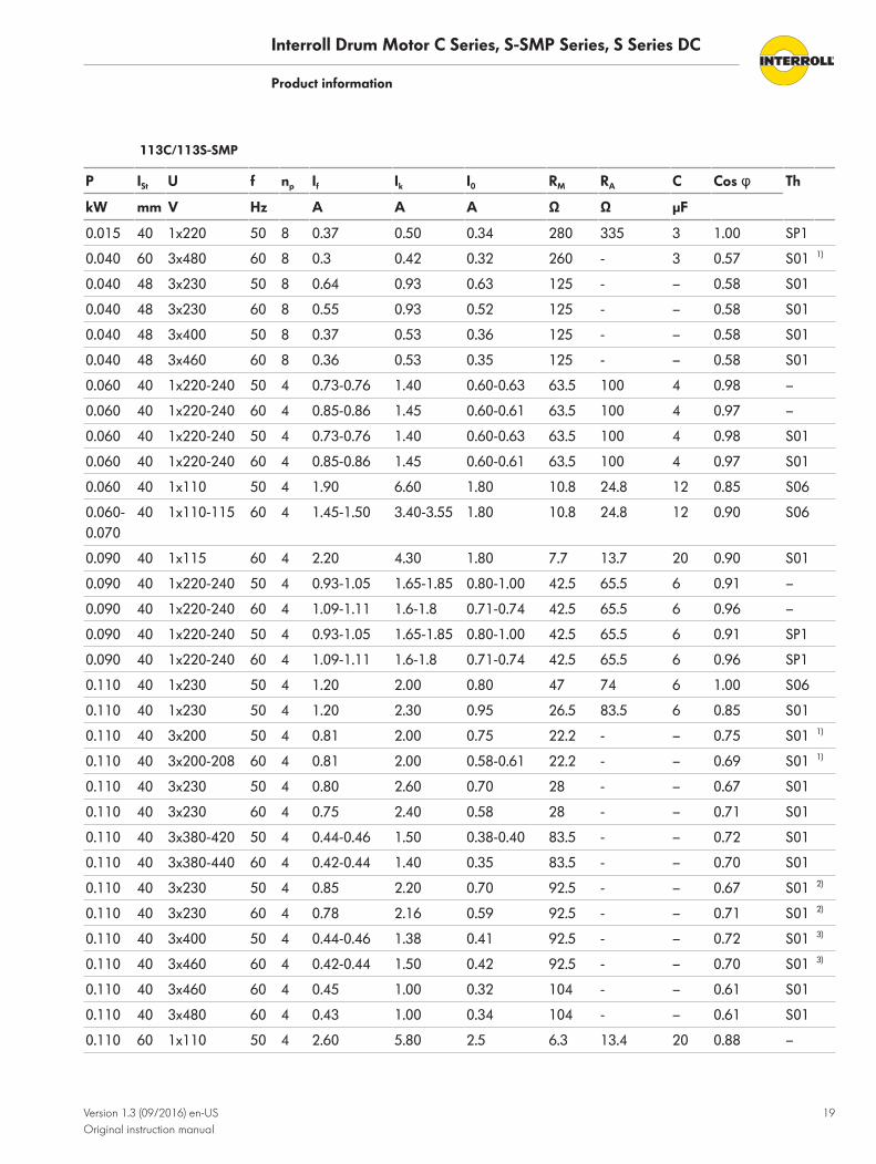
113C/113S-SMP
P ISt U f np If Ik I0 RM RA C Cos φ Th
kW mm V Hz A A A Ω Ω µF
0.015 40 1x220 50 8 0.37 0.50 0.34 280 335 3 1.00 SP1
0.040 60 3x480 60 8 0.3 0.42 0.32 260 - 3 0.57 S01 1)
0.040 48 3x230 50 8 0.64 0.93 0.63 125 - – 0.58 S01
0.040 48 3x230 60 8 0.55 0.93 0.52 125 - – 0.58 S01
0.040 48 3x400 50 8 0.37 0.53 0.36 125 - – 0.58 S01
0.040 48 3x460 60 8 0.36 0.53 0.35 125 - – 0.58 S01
0.060 40 1x220-240 50 4 0.73-0.76 1.40 0.60-0.63 63.5 100 4 0.98 –
0.060 40 1x220-240 60 4 0.85-0.86 1.45 0.60-0.61 63.5 100 4 0.97 –
0.060 40 1x220-240 50 4 0.73-0.76 1.40 0.60-0.63 63.5 100 4 0.98 S01
0.060 40 1x220-240 60 4 0.85-0.86 1.45 0.60-0.61 63.5 100 4 0.97 S01
0.060 40 1x110 50 4 1.90 6.60 1.80 10.8 24.8 12 0.85 S06
0.060-0.070
40 1x110-115 60 4 1.45-1.50 3.40-3.55 1.80 10.8 24.8 12 0.90 S06
0.090 40 1x115 60 4 2.20 4.30 1.80 7.7 13.7 20 0.90 S01
0.090 40 1x220-240 50 4 0.93-1.05 1.65-1.85 0.80-1.00 42.5 65.5 6 0.91 –
0.090 40 1x220-240 60 4 1.09-1.11 1.6-1.8 0.71-0.74 42.5 65.5 6 0.96 –
0.090 40 1x220-240 50 4 0.93-1.05 1.65-1.85 0.80-1.00 42.5 65.5 6 0.91 SP1
0.090 40 1x220-240 60 4 1.09-1.11 1.6-1.8 0.71-0.74 42.5 65.5 6 0.96 SP1
0.110 40 1x230 50 4 1.20 2.00 0.80 47 74 6 1.00 S06
0.110 40 1x230 50 4 1.20 2.30 0.95 26.5 83.5 6 0.85 S01
0.110 40 3x200 50 4 0.81 2.00 0.75 22.2 - – 0.75 S01 1)
0.110 40 3x200-208 60 4 0.81 2.00 0.58-0.61 22.2 - – 0.69 S01 1)
0.110 40 3x230 50 4 0.80 2.60 0.70 28 - – 0.67 S01
0.110 40 3x230 60 4 0.75 2.40 0.58 28 - – 0.71 S01
0.110 40 3x380-420 50 4 0.44-0.46 1.50 0.38-0.40 83.5 - – 0.72 S01
0.110 40 3x380-440 60 4 0.42-0.44 1.40 0.35 83.5 - – 0.70 S01
0.110 40 3x230 50 4 0.85 2.20 0.70 92.5 - – 0.67 S01 2)
0.110 40 3x230 60 4 0.78 2.16 0.59 92.5 - – 0.71 S01 2)
0.110 40 3x400 50 4 0.44-0.46 1.38 0.41 92.5 - – 0.72 S01 3)
0.110 40 3x460 60 4 0.42-0.44 1.50 0.42 92.5 - – 0.70 S01 3)
0.110 40 3x460 60 4 0.45 1.00 0.32 104 - – 0.61 S01
0.110 40 3x480 60 4 0.43 1.00 0.34 104 - – 0.61 S01
0.110 60 1x110 50 4 2.60 5.80 2.5 6.3 13.4 20 0.88 –

Interroll Drum Motor C Series, S-SMP Series, S Series DC
Product information
20 Version 1.3 (09/2016) en-USOriginal instruction manual
P ISt U f np If Ik I0 RM RA C Cos φ Th
kW mm V Hz A A A Ω Ω µF
0.110 60 1x110-115 60 4 2.15-2.20 5.60 1.44-1.52 6.3 13.4 16 0.94 –
0.110 60 1x110-115 50 4 2.60 5.80 2.50-2.75 6.3 13.4 20 0.88 S06
0.110 60 1x110-115 60 4 2.15-2.20 5.60 1.44-1.58 6.3 13.4 16 0.94 S06
0.110 60 1x200-240 50 4 1.00-1.13 2.40 0.85-0.90 32.5 51.5 6 0.88 –
0.110 60 1x208-240 60 4 1.05-1.27 2.30 0.70-0.88 32.5 51.5 6 0.99 –
0.110 60 1x200-240 50 4 1.00-1.13 2.4 0.85-0.90 32.5 51.5 6 0.88 SP1
0.110 60 1x208-240 60 4 1.05-1.27 2.03 0.70-0.88 32.5 51.5 6 0.99 SP1
0.110 60 1x200-240 50 4 1.00-1.13 2.40 0.85-0.90 32.5 51.5 6 0.88 S01
0.110 60 1x208-240 60 4 1.05-1.27 2.30 0.70-0.88 32.5 51.5 6 0.99 S01
0.110 75 1x220-240 50 6 1.16 2.20 1.05 45.9 55.5 8 0.99 S01 1)
0.110 75 1x220-240 60 6 1.40-1.43 2.25 1.00 45.9 55.5 8 0.99 S01
0.110 75 3x220-240 50 6 1.00-1.10 2.25 0.98 30 - – 0.67 S01
0.110 75 3x240 60 6 0.98 1.90 0.98 30 - – 0.67 S01
0.110 75 3x380-420 50 6 0.60-0.64 1.30 0.57-0.65 92 - – 0.62 S01
0.110 75 3x440 60 6 0.57 1.10 0.55 92 - – 0.62 S01
0.150 75 1x110-115 50 4 3.60 7.80 3.10 4 9.8 25 0.80 S06
0.150 75 1x110-115 60 4 2.80 7.50 1.95 4 9.8 20 0.89 S06
0.160 60 3x220-240 50 4 0.97-1.00 3.40 0.78-0.83 24.2 - – 0.76 S01
0.160 60 3x220-240 60 4 0.96-1.03 3.40 0.71 24.2 - – 0.79 S01
0.160 48 3x210-240 50 4 0.97-1.00 3.17 0.67 64.1 - – 0.76 S01 2)
0.160 48 3x210-240 60 4 0.87 2.97 0.67 64.1 - – 0.79 S01
0.160 48 3x380-420 50 4 0.56-0.58 1.83 0.49 64.1 - – 0.76 S01 3)
0.160 48 3x380-440 60 4 0.52 2.00 0.47 64.1 - – 0.78 S01
0.180 60 3x200 50 4 1.22 4.80 1.06 12.2 - – 0.71 S01
0.180 60 3x200-208 60 4 1.09 4.50-4.70 0.83-0.87 12.2 - – 0.75-0.72 S01
0.180 66 3x210-240 50 4 1.43 3.40 0.78-0.83 47 - – 0.76 S01 4)
0.180 66 3x210-240 60 4 1.23 3.30 0.7-0.73 47 - – 0.73 S01
0.180 66 3x380-420 50 4 0.61-0.63 2.30 0.51 47 - – 0.76 S01 4)
0.180 66 3x460 60 4 0.63-0.70 2.60 0.49 47 - – 0.73 S01
0.180 75 3x210-240 50 4 1.00 4.00 0.78-0.83 15 - – 0.76 S01 4)
0.180 75 3x210-240 60 4 1.00-1.25 4.75 0.70-0.73 15 - – 0.73 S01
0.180 75 3x380-420 50 4 0.61-0.63 2.30 0.45-0.48 47 - – 0.76 S01 4)
0.180 75 3x380-440 60 4 0.63-0.70 2.60 0.40-0.42 47 - – 0.73 S01
0.180 75 3x440 50 4 0.56 1.85 0.45 58 - – 0.76 S01
0.180 75 3x460-500 60 4 0.58-0.51 2.00 0.43 58 - – 0.66 S01

Interroll Drum Motor C Series, S-SMP Series, S Series DC
Product information
Version 1.3 (09/2016) en-USOriginal instruction manual
21
P ISt U f np If Ik I0 RM RA C Cos φ Th
kW mm V Hz A A A Ω Ω µF
0.180 75 3x525-575 60 4 0.40-0.47 1.90 0.31-0.40 88.5 - – 0.66-0.73 S06
0.180 75 1x220 50 4 1.51 2.56 1.02 22.4 36.5 8 0.97 S01
0.250 60 3x380-420 50 2 0.68 2.60 0.44 33.5 - – 0.86 S01
1) Not UL-conform2) Use low-voltage cable3) Use high-voltage cable4) Use low-voltage cable with physical insulation
Mechanical data for S-DC-seriesAbbreviations see "List of abbreviations", page 50.
80S DC PN gs i v nA MA FN TE Min. startweight
SLmin
kW m/s min-1 Nm N N kg mm
0.044 3 115.2 0.12 28 12.6 315 2000 100 285
96.0 0.15 35 10.5 263 2000 80 285
78.5 0.18 42 8.6 215 2000 67 285
52.9 0.27 63 5.8 175 2000 52 285
71.6 0.20 47 7.8 145 2000 44 285
63.5 0.23 54 7.0 195 2000 60 285
43.3 0.33 77 4.7 118 2000 36 285
48.8 0.30 70 5.4 135 2000 40 285
19.2 0.76 178 1.6 40 1500 16 285
16.0 0.90 211 1.3 33 1500 13 285
13.1 1.10 258 1.1 28 1500 11 285

Interroll Drum Motor C Series, S-SMP Series, S Series DC
Product information
22 Version 1.3 (09/2016) en-USOriginal instruction manual
113S DC PN gs i v nA MA FN TE Min. startweight
SLmin
kW m/s min-1 Nm N N kg mm
0.044 3 115.2 0.18 26 12.6 223 2000 71 273
96.0 0.21 30 10.5 186 2000 57 273
78.5 0.26 37 8.6 152 2000 47 273
71.6 0.29 42 7.8 138 2000 42 273
63.5 0.32 46 7.0 124 2000 37 273
52.9 0.39 56 5.8 103 2000 31 273
48.8 0.42 60 5.4 96 2000 28 273
43.3 0.47 68 4.7 83 2000 25 273
19.2 1.07 154 1.6 28 1500 11 273
16.0 1.28 184 1.3 23 1500 9 273
13.1 1.56 224 1.1 19 1500 8 273
DimensionsSome dimensions are listed as "SL+". SL is the abbreviation for "shell length" (tube length). Thisdimension can be derived from the RL data on the type plate of the drum motor (see "Type plateof drum motor", page 11). For drum motors 80S and 113C, the RL dimension is identical to theFW data.
• For drum motors 80C/80S-SMP/80S DC: SL = RL - 10• For drum motors 113C/113S-SMP/113S DC: SL = RL - 22
ZZ-Z
Z
B
FW/RL
F=
E =
D =
Dimensions of drum motors 80C/80S-SMP/80S DC

Interroll Drum Motor C Series, S-SMP Series, S Series DC
Product information
Version 1.3 (09/2016) en-USOriginal instruction manual
23
Type Amm
Bmm
Cmm
Dmm
Smm
Fmm
Hmm
FWmm
ELmm
AGLmm
80C, 80S-SMP, 80S-DC convexSL 270 to 612 mm
81.5 80 20 35 45 21 8 SL+10 SL+16 SL+68
80C, 80S-SMP, 80S-DC convexSL 612 to 962 mm
83 81 20 35 45 21 8 SL+10 SL+16 SL+68
80C, 80S-SMP, 80S-DC cylindricalSL 270 to 612 mm
80.5 80.5 20 35 45 21 8 SL+10 SL+16 SL+68
80C, 80S-SMP, 80S-DC cylindricalSL 612 to 962 mm
83 83 20 35 45 21 8 SL+10 SL+16 SL+68
ZZ-Z
Z
B
F=
E =D
=
FW/RL
Dimensions of drum motors 113C/113S-SMP/113S DC
Type Amm
Bmm
Cmm
Dmm
Smm
Fmm
Hmm
FWmm
ELmm
AGLmm
113C, 113S-SMP, 113S-DC convex 113.3 112.5 20 35 45 21 14 SL+22 SL+28 SL+68
113C, 113S-SMP, 113S-DCcylindrical
113.3 113.3 20 35 45 21 14 SL+22 SL+28 SL+68

Interroll Drum Motor C Series, S-SMP Series, S Series DC
Product information
24 Version 1.3 (09/2016) en-USOriginal instruction manual
Shaft caps and screwedcable glands
2.2
Standard shaft cap, aluminum
Shaft cap with cable protection
Connection diagrams for C seriesThese installation and operating instructions list only standard connection diagrams. For otherconnection types, the connection diagram is supplied separately with the drum motor.
Abbreviations, see "List of abbreviations", page 50.
Color coding, see "Color coding", page 51.
Drum motors 80C, 113C
C
F 0
(V)
N.C.
T.C.
bn bk wh bu rd gy
3 1 2 4 5 6
ye/gn
bn bk wh bu rd gy ye/gn3 1 2 4 5 6
Standard connection
Thermal protection as an option. For a drum motor without thermal protection, cores 5 and 6are dummies.

Interroll Drum Motor C Series, S-SMP Series, S Series DC
Product information
Version 1.3 (09/2016) en-USOriginal instruction manual
25
bn bkwh
3 12
3 12
ye/gn
bn
F
0
C
bkwh ye/gn
N.C.
T.C.
Optional connection
Drum motors 80S‑SMP,113S‑SMP
bnbk whbu rd
31 24 5 13 24 5
ye/gn bn bk whbu
R S TR S T
rd ye/gn
3~ 3~
N.C.
T.C.
N.C.
T.C.
Three-phase, 6-core cable
bn bk wh bu rd gy
3 1 2 4 5 6 4 1 2 3 5 6
ye/gn bnbk whbu rd gy ye/gn
1~ 1~
N.C.
T.C.
N.C.
T.C.
C
F 0(V)
C
F 0(V)
Single-phase, 6-core cable

Interroll Drum Motor C Series, S-SMP Series, S Series DC
Product information
26 Version 1.3 (09/2016) en-USOriginal instruction manual
Drum motors 80S DC,113S DC
bn wh
1 2
+ -(V)
Note: For counter clockwise direction of rotation, reverse brown and white.

Interroll Drum Motor C Series, S-SMP Series, S Series DC
Version 1.3 (09/2016) en-USOriginal instruction manual
27
Options and accessories
Asynchronous drum motors with frequency inverters
Torque depends on inputfrequency
Operatingfrequency Hz
5 10 15 20 25 30-50 55 60 65 70
Available motor torque in %
Motorratedfrequency
50 Hz 80 85 90 95 100 100 91 83 77 71
60 Hz 75 80 85 90 95 100 100 100 92 86
Operatingfrequency Hz
75 80 85 90 95 100 105 110 115 120
Available motor torque in %
Motorratedfrequency
50 Hz 67 63 58 51 46 42 38 34 32 29
60 Hz 80 75 71 68 63 60 55 50 45 42
Value 1: based on motor rated frequency 50 Hz
Value 2: based on motor rated frequency 60 Hz
The torque dependency depicted in the figure above is expressed as P = T x ω. At a reducedoperating frequency of below 20/24 Hz, motor torque is reduced by changing heat dissipationconditions. The power loss dissipation is a result of the oil quantity, in contrast to standard fanmotors. For frequencies starting at 80- 85/95- 100 Hz, the curve for the output torque does nothave the hyperbolic shape indicated above, but is instead replaced by a quadratic function thatis the result of the effect of the pull-out torque and the voltage. The output/frequencycharacteristics of most frequency inverters supplied with 3 x 400 V/3 x 460 V can beparameterized to 230 V/50 Hz in order to connect 230-V motors. This causes further losses inthe motor and leads to its overheating.

Interroll Drum Motor C Series, S-SMP Series, S Series DC
Options and accessories
28 Version 1.3 (09/2016) en-USOriginal instruction manual
Frequency inverterparameters
• Clock frequency: A high clock frequency leads to a better utilization factor of the motor.Optimum frequencies are 8 or 16 kHz. Parameters such as smooth running test quality(motor is running smoothly) and noise development are also affected positively by highfrequencies.
• Voltage increase: Interroll motor windings are dimensioned for a rated voltage increaserate of 1 kV/μs. If a frequency inverter generates a steeper voltage increase, motor chokescan be installed between frequency inverter and motor. But since all drum motors fromInterroll run in an oil bath, the risk of overheating or damage to the motor due to largevoltage increases is extremely low. If in doubt, please contact your local Interroll dealer.
• Voltage: If a frequency inverter with single-phase supply is installed at the drum motor, itmust be ensured that the specified motor is dimensioned for the supply voltage used and isconnected accordingly!
• Output frequency: Caution should be exercised for applications with output frequenciesabove 87/100 Hz. High frequencies can cause noise, vibrations and resonances, and reducethe rated output torque of the motor. Caution should be exercised when using inverters withfrequencies below 25 Hz since this could result in overheating or power loss of the motor. Ifin doubt, please contact your local Interroll dealer.
• Motor output: Not all frequency inverters can operate motors with more than 6 poles and/or output powers below 0.2 KW/0.25 HP. If in doubt, please contact your local Interrolldealer or the supplier of the frequency inverters.
• Frequency inverter parameters: Frequency inverters are usually delivered with a standardparameter set. This allows the inverter to be used immediately. However, the standardparameters may not be optimally set for your motor and may have to be adjusted to thespecific motor.

Interroll Drum Motor C Series, S-SMP Series, S Series DC
Options and accessories
Version 1.3 (09/2016) en-USOriginal instruction manual
29
Thermal protectionUnder normal operating conditions, the thermal circuit breaker integrated in the stator winding isclosed. When the motor limit temperature is reached (overheating), the switch opens at a presettemperature (depending on the insulation class of the winding) to prevent damage to the motor.
WARNINGThe thermal circuit breaker is automatically reset after the motor has cooled off.
Inadvertent start-up of the motor
4 The thermal circuit breaker must be connected in series with a suitable relay or contactor sothat the current supply to the motor is safely interrupted when the switch trips.
4 After the switch has tripped, wait until the motor has cooled off, and ensure prior to switch-on that there is no danger to persons.
Standard design:Temperature limiter,
automatically resetting
Service life: 10,000 cycles
AC cos φ = 1 2.5 A 250 VAC
cos φ = 0.6 1.6 A 250 VAC
DC 1.6 A 24 VDC
1.25 A 48 VDC
Service life: 2,000 cycles
AC cos φ = 1 6.3 A 250 VAC
Reset temperature 40 K ± 15 K
Resistance < 50 mΩ
Contact bounce time < 1 ms

Interroll Drum Motor C Series, S-SMP Series, S Series DC
30 Version 1.3 (09/2016) en-USOriginal instruction manual
Transport and storage
Transport
CAUTIONImproper transport poses a risk of injury.
4 Transport-related tasks should only be carried out by qualified and authorized persons.4 For drum motors with a diameter of 136 mm or more, use a crane or hoisting equipment
during the transport. The rated load of the crane or hoisting equipment must be greaterthan the weight of the drum motor. Crane rope/cable and hoisting equipment must besecurely fastened to the shafts of the drum motor during lifting.
4 Do not stack pallets.4 Before the transport, ensure that the drum motor is sufficiently secured.
NOTICERisk of damages to the drum motor due to improper transport
4 Avoid serious impacts during transport.4 Do not lift the drum motor at the cable or terminal box.4 Do not transfer the drum motors between warm and cold environments. This may lead to the
formation of condensation.4 For the transport in shipping containers, ensure that the temperature in the container is not
permanently above 70 °C (158 °F).4 Ensure that motors of the S-series that are intended for vertical mounting are transported in
horizontal position.
4 Check each drum motor visually for damage after transport.4 In the event of damage, take photos of the damaged parts.4 In case of a transport damage, immediately notify the carrier and Interroll to avoid losing
any claims for compensation.

Interroll Drum Motor C Series, S-SMP Series, S Series DC
Transport and storage
Version 1.3 (09/2016) en-USOriginal instruction manual
31
Storage
CAUTIONRisk of injury due to improper storage
4 Do not stack pallets.4 Do not stack more than four cardboard boxes on top of each other.4 Ensure that proper fastening is in place.
4 Store the drum motor in a clean, dry and enclosed location at +15 to +30 °C; protect itfrom moisture and humidity.
4 For storage times exceeding three months, turn the shaft occasionally to prevent damage tothe shaft seals.
4 Inspect each drum motor for damage after storage.

Interroll Drum Motor C Series, S-SMP Series, S Series DC
32 Version 1.3 (09/2016) en-USOriginal instruction manual
Assembly and installation
Warning notices concerning the installation
CAUTIONRotating parts and inadvertent startup of the motor
Risk of crushing for fingers
4 Do not reach into areas between drum motor and conveyor belts or roller chains.4 Install a protection device (such as a guard plate) to prevent fingers from getting trapped in
the chain belts or roller chains.4 Install an appropriate warning on the conveyor.
NOTICERisk of damage leading to failure or shortened service life of the drum motor
4 Observe the following safety information.
4 Do not drop or mishandle the drum motor to avoid internal damages.4 Prior to the installation, inspect each drum motor for damage after storage.4 Do not hold, carry, or support the drum motor by the wires extending out of the mounting
shaft to avoid damage to the internal parts and seals.4 Do not twist the motor cable.4 Do not overtension the belt.
Installing the drum motor
Positioning the drummotor
4 Ensure that the data on the type plate are correct and match the ordered and confirmedproduct.
A special design must be used for installing the drum motor in non-horizontal applications. Theexact version must be specified at the time of ordering. In case of doubt, contact Interroll.
The drum motor must be mounted horizontally with a clearance of +/- 5° (drum motor 113S:+/- 2°), unless specified otherwise in the order confirmation.
-2°-5°
+2°+5°
Position of the drum motor

Interroll Drum Motor C Series, S-SMP Series, S Series DC
Assembly and installation
Version 1.3 (09/2016) en-USOriginal instruction manual
33
Installing the motor withmounting brackets
The mounting brackets must be sufficiently robust to withstand the motor torque.
4 Install the brackets at the conveyor or machine frame. Ensure that the drum motor is installedparallel to the idler pulley and at a right angle to the conveyor frame.
4 Insert the shaft ends of the drum motor into the mounting brackets according to the"Mounting position" table (see above).
4 If the shaft has to be attached to the mounting brackets (e.g. with a screw through a crossbore in the journal), it should be done on one side only so that the other side is axiallymovable in case of thermal expansion.Fastening for motors of S and D series as well as motors of type 80i, 113i, 217i and 315i: onthe side without cable connection Fastening for motors of type 138i, 165i, 216i and 113E:on the side of the cable connection
4 Ensure that at least 80% of the drum motor flats are held by the mounting brackets.4 Ensure that the distance between the flats and the bracket is not more than 0.4 mm.4 If the drum motor is used for frequent reversing duty or for start/stop operation: Ensure that
there is no gap between the flats and mounting brackets.
The drum motor can also be installed without mounting brackets. In this case, the shaft ends mustbe installed into corresponding recesses in the conveyor frame; these recesses must bereinforced in such a way that they meet the aforementioned requirements.
1.0 mm
Axial clearance
max. 0.4 mm
Torsion clearance
4 If necessary, install a support plate above the mounting bracket to secure the drum motoraxle. However, ensure that the axle remains movable to one side to compensate for thermalexpansion.

Interroll Drum Motor C Series, S-SMP Series, S Series DC
Assembly and installation
34 Version 1.3 (09/2016) en-USOriginal instruction manual
Belt assembly
Belt width / tube lengthNOTICERisk of overheating if belt is too small
4 Ensure that the drum motor is operated with a conveyor belt that covers at least 70 % of thedrum tube.
For drum motors with less than 70 % belt contact and drum motors with form-fit driven belts orwithout belt, a motor dimensioned for this purpose is required. This must be specified at the timeof ordering. If in doubt, please contact Interroll.
Belt adjustment Convex tubes center and guide the belt during regular operation. Nevertheless, the belt shouldbe carefully aligned, frequently checked during startup and readjusted depending on the load.
NOTICEAdjustment errors can lead to a shortened service life as well as damages of the beltand the drum motor ball bearings.
4 Adjust the drum motor, belt and idler pulleys according to the instructions in this instructionmanual.
4 Adjust the belt with the synchronous returning rollers and support rollers and/or (if available)with the idler pulleys or snub pulleys.
4 Check the diagonal dimensions (between the shafts of the drum motor and the shafts of theend/guide rollers or from belt edge to belt edge).The difference must not be greater than 0.5 %.
Diagonal check
The distance between the belt and the gliding plate must not exceed 3 mm.

Interroll Drum Motor C Series, S-SMP Series, S Series DC
Assembly and installation
Version 1.3 (09/2016) en-USOriginal instruction manual
35
0-3 mm
Belt position
Tensioning the belt The required belt tension depends on the respective application. The pertinent information islocated in the catalog of the belt manufacturer, or contact Interroll.
NOTICEOvertensioned belts can lead to a shortened service life, wear of bearings or oilleakage.
4 Do not tension the belt beyond the value recommended by the manufacturer or specified inthe product tables of the catalog.
4 Link belts, steel belts, Teflon-coated fiberglass belts and hot-formed PU belts should not betensioned (see the instructions from the belt manufacturer).
4 Adjust the belt tension by tightening or loosening the corresponding screws on both sides ofthe conveyor to ensure that the drum motor is positioned at a right angle to the conveyorframe and parallel to the end roller/idler pulley.
4 Tension the belt only so much that belt and load are being driven.
Rubber coatingA rubber coating that was applied retroactively can cause the drum motor to overheat. Forsome drum motors, there may be restrictions concerning the thickness of the rubber coating.
To avoid a thermal overload, the required output should be multiplied by 1.2.
Please contact Interroll concerning the type and maximum thickness of a rubber coating, if youwant to apply one.
Warning notices concerning the electrical installation
WARNINGElectrocution due to improper installation
4 All electrical work should only be performed by qualified and authorized persons.4 Disconnect the power supply before installing, removing or rewiring the drum motor.4 Always observe the connection instructions and ensure that the power and control circuits of
the motor are correctly connected.4 Ensure that metal conveyor belt frames are sufficiently grounded.

Interroll Drum Motor C Series, S-SMP Series, S Series DC
Assembly and installation
36 Version 1.3 (09/2016) en-USOriginal instruction manual
NOTICEDamage of the drum motor from incorrect power supply
4 Do not connect an AC drum motor to an excessively high DC voltage supply and a DC drummotor to an AC voltage supply – this will lead to irreparable damages.
4 Do not connect drum motors of the D-series directly to the supply system. D-drum motorsmust be operated via suitable frequency inverters or servo drive controllers.
Electrical connection of the drum motor
Connecting the drummotor – with a cable
4 Ensure that the motor is connected to the correct supply voltage according to the motor typeplate.
4 Ensure that the drum motor is correctly grounded with the yellow-green cable.4 Connect the motor according to the connection diagrams (see "Connection diagrams for C
series", page 24).
Single-phase motor If a starting torque of 100% is required, single-phase drum motors,should be connected to astarting capacitor and a run capacitor. An operation without starting capacitor can reduce thestarting torque to 70 % of the rated torque listed in the Interroll catalog.
Interroll recommends the use of capacitor type class B 10,000 hours / 450 V according to EN60252.
Connect the starting capacitors according to the connection diagrams (see "Connection diagramsfor C series", page 24).
External motor protection The motor must be protected by a suitable fuse or other external protective device. Theprotective device must be set to the rated current of the corresponding motor (see type plate).
The voltage supply must be protected against a potential counter EMF. The motor generates acounter EMF if an external force acts upon it.
4 Install one overload protection for each motor. Such a protection can consist of, e.g. a slowfuse, a circuit breaker or a current limiter.
Integrated thermalprotection CAUTION
Accidental motor start
Crushing hazard for fingers
4 Connect the integrated thermal circuit breaker to an external control device that interruptsthe current supply to the motor at all poles in case of overheating.
4 After the thermal circuit breaker has tripped, examine and remove the cause for overheatingbefore the current supply is reactivated.
The standard maximum switching current of the thermal circuit breaker is 2.5 A. For otheroptions, please contact Interroll.

Interroll Drum Motor C Series, S-SMP Series, S Series DC
Assembly and installation
Version 1.3 (09/2016) en-USOriginal instruction manual
37
For operational safety, the motor must be safeguarded against overload with an external motorprotection, as well as an integrated thermal protection; otherwise, there is no warranty if themotor fails.
Frequency inverter Asynchronous drum motors can be operated with frequency inverters. Frequency inverters fromInterroll are general adjusted to factory setting and have to be parameterized for the respectivedrum motor. For this purpose, Interroll can supply parameterization instructions. In this case,please contact your local Interroll partner.
4 If no frequency inverter from Interroll is used, the frequency inverter must be correctlyparameterized according to the specified motor data. Interroll can provide only very limitedsupport for frequency inverters that are not being sold by Interroll.
4 Resonance frequencies in the power supply line must be prevented since the create voltagespikes in the motor.If the cable is too long, frequency inverters generate resonance frequencies in the linebetween frequency inverter and motor.
4 Use a completely shielded cable to connect the frequency inverter to the motor.4 Install a sine-wave filter or a motor choke if the cable is longer than 10 meter or if a
frequency inverter controls several motors.4 Ensure that the cable shield is connected to a grounded part according to the
electrotechnical guidelines and local EMC recommendations.4 Always observe the installation guidelines of the frequency inverter manufacturer.

Interroll Drum Motor C Series, S-SMP Series, S Series DC
38 Version 1.3 (09/2016) en-USOriginal instruction manual
Initial startup and operation
Initial startupThe drum motor may be put into operation only if it is correctly installed and connected to thepower supply and all rotating parts have been fitted with the corresponding protective devicesand guards.
Checks before the initialstartup
The drum motor is filled with the correct oil quantity at the factory and ready for installation.Prior to the initial startup of the motor, the following steps have to be performed:
4 Ensure that the motor type plate matches the version ordered.4 Ensure that no contact points exist between objects, conveyor belts and rotating or moving
parts.4 Ensure that the drum motor and the conveyor belt can move freely.4 Ensure that the belt features the correct tension according to the recommendations from
Interroll.4 Ensure that all bolts are tightened according to the specifications.4 Ensure that no additional dangerous areas arise due to interfaces to other components.4 Ensure that the drum motor is correctly wired and connected to the voltage supply with the
correct voltage.4 Check all safety devices.4 Ensure that no bystanders are in dangerous areas around the conveyor.4 Ensure that the external motor protection is correctly adjusted to the rated motor current
and a corresponding switching device can switch off the motor voltage at all poles if theintegrated thermal circuit breaker trips.

Interroll Drum Motor C Series, S-SMP Series, S Series DC
Initial startup and operation
Version 1.3 (09/2016) en-USOriginal instruction manual
39
Operation
CAUTIONRotating parts and accidental starting
Risk of crushing for fingers
4 Do not reach between drum motor and belt.4 Do not remove the protection device.4 Keep fingers, hair and loose clothing away from the drum motor and the belt.4 Keep wristwatches , rings, necklaces, piercings and comparable jewelry away from the drum
motor and the belt.
NOTICEDamage of drum motor in reversing operation
4 Ensure that a time delay is in place between forward and reversing movement. Beforereversing, the motor must come to a complete standstill.
If exact speeds are required, a frequency inverter and/or encoder may have to be used.The specified rated speeds of the motor can deviate by ± 10 %. The belt speed indicated on thetype plate is the calculated speed at the drum diameter under full load, rated voltage and ratedfrequency.
Checks before everystartup
4 Check the drum motor for visible damage.4 Ensure that no contact points exist between objects, conveyor belts and rotating or moving
parts.4 Ensure that the drum motor and the conveyor belt can move freely.4 Check all safety devices.4 Ensure that no bystanders are in dangerous areas around the conveyor.4 Clearly specify and monitor the way materials are placed on the conveyor.
Procedure in case of accident or fault4 Stop the drum motor at once and ensure that it cannot be started accidentally.4 In case of an accident: Provide first aid and make an emergency call.4 Inform the responsible person.4 Have the malfunction repaired by qualified persons.4 Start the drum motor only after this has been approved by qualified persons.

Interroll Drum Motor C Series, S-SMP Series, S Series DC
40 Version 1.3 (09/2016) en-USOriginal instruction manual
Maintenance and cleaning
Warning notices concerning maintenance and cleaning
CAUTIONRisk of injury due to improper handling or accidental motor starts
4 Maintenance work and cleaning must only be performed by qualified and authorizedpersons.
4 Perform maintenance work only after switching off the power. Ensure that the drum motorcannot be turned on accidentally.
4 Set up signs indicating that maintenance work is in progress.
Preparation for maintenance and cleaning by hand4 Switch off the power supply to the drum motor.4 Switch off the main power switch to switch off the drum motor.4 Open terminal box or distribution box and disconnect the cables.4 Attach a sign to the control station that maintenance work is in progress.
MaintenanceGenerally, Interroll drum motors do not have to be maintained and require no special careduring their regular service life. Nevertheless, certain checks have to be performed at regularintervals:
Checking the drum motor 4 Ensure daily that the drum motor can rotate freely.4 Check the drum motor for visible damage every day.4 Ensure daily that the belt is correctly aligned and centered on the drum motor as well as
parallel to the frame of the conveyor. Correct the alignment as necessary.4 Ensure weekly that motor shaft and brackets are firmly fastened to the conveyor frame.4 Ensure weekly that cables, lines and connections are in good condition and securely
fastened.4 Refill synthetic Shell Cassida RLS 2 in food-grade quality every week, if there are lubricating
nipples.
Oil change The oil of the drum motor does not have to be changed.
Replacing drum motors If a drum motor is damaged or defective, it must be removed before a repair or a replacement(see "Shutdown", page 48 and see "Installing the drum motor", page 32).

Interroll Drum Motor C Series, S-SMP Series, S Series DC
Maintenance and cleaning
Version 1.3 (09/2016) en-USOriginal instruction manual
41
Cleaning
Material deposited on the drum motor or the underside of the belt can lead to slippage of thebelt and to damage to the belt. Material deposited between belt and gliding plate or rollers canalso lead to a decrease of the belt speed and to increased current consumption. Regularcleaning guarantees a high effect on the drive and a correct alignment of the belt.
4 Remove foreign material from the drum shell.4 Do not use sharp-edged tools to clean the drum shell.

Interroll Drum Motor C Series, S-SMP Series, S Series DC
42 Version 1.3 (09/2016) en-USOriginal instruction manual
Troubleshooting
Troubleshooting
Fault Possible cause Remedy
Motor does not start or stopsduring operation
No power supply Check voltage supply.
Incorrect connection or loose/defective cable connection
Check connection according to connection diagram.Check whether cables are defective or connections are loose.
Motor overheating See the fault "Motor heats up in regular operation".
Motor overload Disconnect main power supply, determine and remove cause ofoverload.
Internal thermal circuit breakertripped/failure
Check whether it is overloaded or overheating. After coolingoff, check continuity of internal thermal protection. See the fault"Motor heats up in regular operation".
External thermal circuitbreaker tripped/failure
Check whether it is overloaded or overheating. Checkcontinuity and function of external overload protection.
Motor winding phase error Replace the drum motor or contact your local Interroll dealer.
Motor winding short circuit(insulation fault)
Replace the drum motor or contact your local Interroll dealer.
Drum shell or conveyor beltblocked
Ensure that belt and drum motor are not being blocked and allrollers and drum shells can turn freely.If the drum motor cannot turn freely, the gear box or thebearing may be blocked. In this case, contact your localInterroll dealer.
Low ambient temperature/highoil viscosity
Check whether the oil viscosity is suitable for the currentambient temperature. If not, fill in new oil with the correctviscosity.Install a heater or more powerful drum motor. In this case,contact your local Interroll dealer.
Motor is running, but drumshell does not turn
Transfer loss Contact local Interroll dealer.

Interroll Drum Motor C Series, S-SMP Series, S Series DC
Troubleshooting
Version 1.3 (09/2016) en-USOriginal instruction manual
43
Fault Possible cause Remedy
Motor heats up in regularoperation
Overload of the drum motor Check rated current for overload.
Ambient temperature above40 °C
Check ambient temperature. If the ambient temperature is toohigh, install a cooling unit. Contact local Interroll dealer.
Excessive or frequent stops/starts
Check whether the number of stops/starts corresponds to thespecifications of the drum motor and reduce this number ifnecessary. Install a frequency inverter to optimize the motoroutput.
Belt tension too high Check belt tension and reduce as necessary.
Motor is not suitable for theapplication
Check whether the application meets the specifications of thedrum motor.Use special reduced-power motors for the operation with linkbelts or without belts.
Coating too thick Replace coating or contact local Interroll dealer.
Wrong voltage supply Check the voltage supply.For single-phase motors, ensure that the correct starting or runcapacitors are used.
Wrong settings at frequencyinverter
Check whether the frequency inverter settings meet thespecifications of the drum motor and change them if necessary.
Loud noise of drum motor inregular operation
Wrong settings at frequencyinverter
Check whether the frequency inverter settings meet thespecifications of the drum motor and change them if necessary.
Loose motor mount Check motor mount, shaft tolerances and fastening screws.
Belt tension too high Check belt tension and reduce as necessary.
Wrong/incorrect profilebetween drum shell and belt
Ensure that belt and drum profile match and are correctlyconnected. Replace as needed.
An outer conductor failed Check connection, check supply system.
Drum motor vibrates heavily Wrong settings at frequencyinverter
Check whether the frequency inverter settings meet thespecifications of the drum motor and change them if necessary.
Loose motor mount Check motor mount, shaft tolerances and fastening screws.
Drum motor runs unevenly Check whether the specifications of the drum motor contain astatic or dynamic balancing and adjust it.
Drum motor runs withinterruptions
Drum motor/belt isoccasionally or partiallyblocked
Ensure that belt and drum motor are not being blocked and allrollers and drum shells can turn freely.
Wrong or loose power cableconnection
Check connections.
Gear box is damaged Check by hand if the drum shell can be turned freely.If not, replace drum motor or contact local Interroll dealer.
Wrong or faulty voltagesupply
Check the voltage supply.For single-phase motors: Check capacitors.

Interroll Drum Motor C Series, S-SMP Series, S Series DC
Troubleshooting
44 Version 1.3 (09/2016) en-USOriginal instruction manual
Fault Possible cause Remedy
Drum motor/belt runs moreslowly than specified
Wrong motor speed ordered/delivered
Check drum motor specifications and tolerances.Replace drum motor or contact local Interroll dealer.
Drum motor/belt isoccasionally or partiallyblocked
Ensure that belt and drum motor are not being blocked and allrollers and drum shells can turn freely.
Wrong settings at frequencyinverter
Check whether the frequency inverter settings meet thespecifications of the drum motor and change them if necessary.
Belt slips See the fault "Belt slips on drum motor".
Drum motor/belt runs moreslowly than specified
Coating slips on the drum shell Check condition of coating and fix coating on drum shell.Replace coating. Sandblast or abrade drum surface toguarantee a good adhesion of the coating.
Use of a 60-Hz motor in a 50-Hz supply system
Check whether motor specifications and tolerances correspondto the supply voltage/frequency.Replace drum motor or contact local Interroll dealer.
Drum motor runs faster thanspecified.
Wrong motor speed ordered/delivered
Check drum motor specifications and tolerances.Replace drum motor or contact local Interroll dealer.
Wrong settings at frequencyinverter
Check whether the frequency inverter settings meet thespecifications of the drum motor and change them if necessary.
Use of a 50-Hz motor in a 60-Hz supply system
Check whether motor specifications and tolerances correspondto the supply voltage/frequency.Replace drum motor or contact local Interroll dealer.
Thickness of rubber coatingincreased the belt speedbeyond the rated speed of themotor
Measure thickness of rubber coating and check whether thisvalue was considered and calculated in the selection of thedrum motor speed.Reduce thickness of rubber coating or install a frequencyinverter or install new drum motor with lower speed.
Motor winding: one phasefailed
Failure/overload of windinginsulation
Check continuity, current and resistance of phase winding.Replace drum motor or contact local Interroll dealer.
Motor winding: two phasesfailed
Power failure at one phasewhich leads to overload at theother two phases / separatingfailure
Check power supply to all phases. Check continuity, currentand resistance of phase winding.Replace drum motor or contact local Interroll dealer.
Motor winding: all threephases failed
Motor overload / wrongcurrent connection
Check whether the correct supply voltage is present.Check continuity, current and resistance of phase winding.Replace drum motor or contact local Interroll dealer.

Interroll Drum Motor C Series, S-SMP Series, S Series DC
Troubleshooting
Version 1.3 (09/2016) en-USOriginal instruction manual
45
Fault Possible cause Remedy
Belt slips on drum motor Belt blocked Ensure that belt and drum motor are not being blocked and allrollers and drum shells can turn freely.
Friction too low between drummotor and belt
Check condition and tension of the belt.Check condition of drum shell or coating.Check whether oil or grease is between belt and drum motor.
Friction too high between beltand bracket/gliding plate
Check underside of belt and gliding plate for contamination /defective surface coating.Check whether water entered between belt and gliding plateand a suction/draft occurs.
Belt tension too low Check condition of belt and tension or shorten it.
Drum profile too low for linkbelt or wrong
Ensure that belt and drum profile / teeth are correctlyconnected.Ensure that height and tension of belt meets the manufacturerdata.
Oil, lubricant or greasebetween belt and drum shell of drum motor
Remove excess oil, grease or lubricant.Ensure correct functioning of cleaning devices.
Diameter of start roller/endroller/transfer roller too lowfor the belt
Check minimum drum diameter for belt. Knife edges/roller withsmall diameter can cause excessive friction and, therefore ahigher current demand.
Coating slips on the drum shell Check condition of coating and fix coating on drum shell.Replace coating. Sandblast or abrade drum surface toguarantee a good adhesion of the coating.
Belt skips on drum motor Belt blocked or materialdeposits on the drum shellsPoor or damaged beltconnectionFriction too high between beltand gliding plate
Ensure that belt and drum shell are not being blocked and allrollers and drum shells can turn freely.Check belt connection.
Conveyor belt loose ordamaged
Check tension and condition of belt and condition of coating.Check belt tracking and belt adjustment.
Wrong coating/sprocketprofile for link belt
See the fault "Belt slips on drum motor".

Interroll Drum Motor C Series, S-SMP Series, S Series DC
Troubleshooting
46 Version 1.3 (09/2016) en-USOriginal instruction manual
Fault Possible cause Remedy
Belt not correctly adjusted /belt does not run centered
Material deposits on drummotor/rollers/belt
Ensure that belt and drum shell are not being blocked and allrollers and drum shells can turn freely.Check belt connection.
Material deposits on rollers Check whether material detaches itself and ensure that thecleaning devices function correctly.
Defective or poorly fixed belt Check belt condition and belt connections.
Belt tension higher on one side Ensure that the belt tension is equal on both sides.
Top/bottom rollers notcorrectly adjusted
Check adjustment of support and returning rollers.
Start roller/end roller/interimroller not correctly adjusted
Check adjustment of drum motor and roller.
Conveyor frame not correctlyadjusted
Ensure that the conveyor frame is rectangular, parallel andstraight over the entire length.
Feeding materials from oneside
Check force or friction at transfer point.
Belt profile not connected withdrum profile
Ensure that belt and drum profile match and are correctlyconnected and adjusted.
Drum camber too low for belt Check belt / drum motor specifications.
Oil exiting at shaft seal Shaft seal worn Check whether negative chemical or aggressive materials/conditions are present.Check operating service life of seals.
Shaft seal damaged Ensure that there are no steel residues, material deposits orother particles at the seals.
Cap bearing damaged/worn Check whether the belt is tensioned or loaded too much.Check whether water or chemicals have entered.
Oil leaking at the cable Loose cable connection socketDefect at internal cable seal
Ensure that cable connection socket and seals are tight and notstressed by overheating or chemicals.
Loose cable connection socket Ensure that cable connection socket and seals at terminal boxare tight and not stressed by overheating or chemicals.
Oil leaking at drum shell/endcap
End cap in drum shell is loose Check whether there are gaps between drum shell and endcap.Check whether the belt is tensioned too much or impact-loaded.
End cap/drum seal defective Check whether the belt is overheated, tensioned too much orimpact-loaded.
Cable defective or damaged Wrong operation by thecustomer or damage duringinstallation
Check type of damage and possible cause.Replace terminal box.
Damage during transport Check type of damage and possible cause.Replace terminal box.

Interroll Drum Motor C Series, S-SMP Series, S Series DC
Troubleshooting
Version 1.3 (09/2016) en-USOriginal instruction manual
47
Fault Possible cause Remedy
Cap bearing failed Overload Check whether the load of the application meets thespecifications of the drum motor.
Impact load Check whether the load of the application meets thespecifications of the drum motor.
Belt tension too high Check whether the belt is tensioned too much. Reduce belttension as necessary.
Poor lubrication Check oil level and installation of drum motor.With vertical installation, check the specifications of the drummotor.
Load or incorrect adjustmentof shaft
Check whether screws have been overtightened and whetherframe or motor mount are incorrectly adjusted.
Shaft seal damaged/worn Check for external contamination.Contact local Interroll dealer.
Loose or fixed seating ofbearing on the shaft
Contact local Interroll dealer.
Gear box failure Overload/impact load orregular wear
Check whether the load of the application meets thespecifications of the drum motor.Check service life.

Interroll Drum Motor C Series, S-SMP Series, S Series DC
48 Version 1.3 (09/2016) en-USOriginal instruction manual
Decommissioning and disposal
Shutdown
CAUTIONRisk of injury due to incorrect handling
4 Shut-down may only be executed by qualified and authorized persons.4 Only shut down the drum motor after switching off the power. Ensure that the drum motor
cannot be turned on accidentally.
4 Disconnect the motor cable from the power supply and motor control.4 Relax the belt.4 Remove holding plate from the motor mount.4 Remove the drum motor out of the conveyor frame.
DisposalThe operator is responsible for the proper disposal of the drum motor.
4 In doing so, industry-specific and local provisions must be observed for the disposal of thedrum motor and its packaging.

Interroll Drum Motor C Series, S-SMP Series, S Series DC
Version 1.3 (09/2016) en-USOriginal instruction manual
49
Appendix
Warranty for Interroll drum motorsInterroll gives a two-year warranty on its drum motor range; the warranty applies tomanufacturing and material defects and starts with the delivery or pickup at the factory. Thewarranty period is based on the regular operational use of the product eight hours per day,provided no written agreement to the contrary is in effect.
As part of this warranty, Interroll repairs or replaces any defective product, free of charge, thatis returned to the factory before the warranty period expires. The warranty period shall not beextended by repairs performed within the framework of the warranty.
Restrictions Interroll and its dealers do not assume any liability for shutdowns or damages to the productthat are due to the following causes:
• Non-observance of the installation or maintenance notes from Interroll• Operation of the motor without suitable motor protection• Not connecting the internal Interroll thermal cut motor protection switch (if available)• Reversing the rotational direction before the motor has reached complete standstill• Use of the drum motor under other conditions as those listed on the type plate and/or in the
current Interroll catalog or in the quote
Repairs, modifications or conversions to the product that are not performed by a qualifiedInterroll technician or service partner, void the warranty, unless such work was clarifiedbeforehand with Interroll in writing.
Exceptions The Interroll warranty excludes any liability for the following damages:• Damages to the shell lagging or other additional materials through regular wear or incorrect
use• Costs for removal and return shipment of the product to Interroll as part of this warranty• Damages to other systems that are used in conjunction with the product• Los of income, injuries or other costs in conjunction with the failure of the product

Interroll Drum Motor C Series, S-SMP Series, S Series DC
Appendix
50 Version 1.3 (09/2016) en-USOriginal instruction manual
List of abbreviations
Electrical data P in kW Power
ISt in mm Stator length
U in V Voltage
f in Hz Frequency
np Number of pole pairs
If in A Full load current
Ik in A Current consumption with blocked motor
I0 in A Zero load current
RM in Ω Main resistor
RA in Ω Phase resistance of auxiliary winding
C in µF Capacitor
cos Power factor
Th Thermal type 125 °C
Mechanical data PN Rated power
gs Gear stages
i Speed ratio
v Rated velocity of tube
nA Rated speed of tube
MA Rated torque of drum motor
FN Rated belt pull of drum motor
TE Max. belt tension
SLmin Minimum tube length

Interroll Drum Motor C Series, S-SMP Series, S Series DC
Appendix
Version 1.3 (09/2016) en-USOriginal instruction manual
51
Connection diagrams TC Thermal protection
NC Not connected
1~ Single-phase motor
3~ Three-phase motor
C Capacitor
Color coding Color coding of cables in the connection diagrams:
rd: red bk: black bn: brown or: orange
ye: yellow gy: gray pk: pink vi: violet
bu: blue gn: green wh: white

Interroll Drum Motor C Series, S-SMP Series, S Series DC
Appendix
52 Version 1.3 (09/2016) en-USOriginal instruction manual
Installation DeclarationIn accordance with the EC Machinery Directive 2006/42/EC, Appendix II 1 B
The manufacturer
Interroll Joki A/SHammerholmen 2-62650 HvidovreDenmark
hereby declares with sole responsibility that the product series• Drum motor C series• Drum motor S-SMP series• Drum motor S series DC version• Cassette C series
fully complies with the safety and health requirements of the Machinery Directive2006/42/EC Appendix I.
The relevant technical documents according to EC Machinery Directive 2006/42/EC, Annex VIIB are available and will be presented to the competent national authorities electronically, ifrequired.
Person authorized to prepare the technical documents: Jan Støvring Jensen, Interroll Joki A/S,Hammerholmen 2-6, 2650 Hvidovre, Denmark.
The partly completed machinery complies with the following EC directives:• Low Voltage Directive 2014/35/EU• EMC Directive 2014/30/EU• RoHS Directive 2011/65/EC
The following harmonized standards were applied:• EN ISO 12100:2010
Initial startup of the partly completed machinery is not permitted until the partlycompleted machinery is incorporated into a machinery which complies with themachinery directive. The EC declaration of conformity must be available according toappendix II A.
The EC declaration of conformity must be available according to Machinery Directive2006/42/EC Annex II 1 A.
April 20, 2016Hvidovre, Denmark
Anders Staf Hansen(General Manager)

Interroll Drum Motor C Series, S-SMP Series, S Series DC
Version 1.3 (09/2016)Original instruction manual
53

Interroll Drum Motor C Series, S-SMP Series, S Series DC
54 Version 1.3 (09/2016)Original instruction manual

Interroll Drum Motor C Series, S-SMP Series, S Series DC
Version 1.3 (09/2016)Original instruction manual
55

For your local contacts please visitinterroll.com/contact
©copyright
Version 1.3 (09/2016)Original instruction manual